EP3000372B1 - Robot cleaner - Google Patents
Robot cleaner Download PDFInfo
- Publication number
- EP3000372B1 EP3000372B1 EP14199941.7A EP14199941A EP3000372B1 EP 3000372 B1 EP3000372 B1 EP 3000372B1 EP 14199941 A EP14199941 A EP 14199941A EP 3000372 B1 EP3000372 B1 EP 3000372B1
- Authority
- EP
- European Patent Office
- Prior art keywords
- unit
- fan
- dust
- cyclone
- robot cleaner
- Prior art date
- Legal status (The legal status is an assumption and is not a legal conclusion. Google has not performed a legal analysis and makes no representation as to the accuracy of the status listed.)
- Active
Links
- 239000000428 dust Substances 0.000 claims description 110
- 238000004891 communication Methods 0.000 claims description 32
- 238000007599 discharging Methods 0.000 claims description 5
- 238000000926 separation method Methods 0.000 claims description 2
- JTJMJGYZQZDUJJ-UHFFFAOYSA-N phencyclidine Chemical class C1CCCCN1C1(C=2C=CC=CC=2)CCCCC1 JTJMJGYZQZDUJJ-UHFFFAOYSA-N 0.000 description 14
- 238000004140 cleaning Methods 0.000 description 12
- 230000008878 coupling Effects 0.000 description 8
- 238000010168 coupling process Methods 0.000 description 8
- 238000005859 coupling reaction Methods 0.000 description 8
- 230000004048 modification Effects 0.000 description 4
- 238000012986 modification Methods 0.000 description 4
- 239000000463 material Substances 0.000 description 3
- 238000000034 method Methods 0.000 description 3
- 230000008569 process Effects 0.000 description 3
- 238000001914 filtration Methods 0.000 description 2
- 230000007246 mechanism Effects 0.000 description 2
- 230000004075 alteration Effects 0.000 description 1
- 238000013461 design Methods 0.000 description 1
- 230000000694 effects Effects 0.000 description 1
- 239000013013 elastic material Substances 0.000 description 1
- 230000002708 enhancing effect Effects 0.000 description 1
- 239000002657 fibrous material Substances 0.000 description 1
- 239000012530 fluid Substances 0.000 description 1
- 238000009434 installation Methods 0.000 description 1
- 238000011160 research Methods 0.000 description 1
- 230000035939 shock Effects 0.000 description 1
- 239000013589 supplement Substances 0.000 description 1
Images


Classifications
-
- A—HUMAN NECESSITIES
- A47—FURNITURE; DOMESTIC ARTICLES OR APPLIANCES; COFFEE MILLS; SPICE MILLS; SUCTION CLEANERS IN GENERAL
- A47L—DOMESTIC WASHING OR CLEANING; SUCTION CLEANERS IN GENERAL
- A47L9/00—Details or accessories of suction cleaners, e.g. mechanical means for controlling the suction or for effecting pulsating action; Storing devices specially adapted to suction cleaners or parts thereof; Carrying-vehicles specially adapted for suction cleaners
- A47L9/28—Installation of the electric equipment, e.g. adaptation or attachment to the suction cleaner; Controlling suction cleaners by electric means
-
- A—HUMAN NECESSITIES
- A47—FURNITURE; DOMESTIC ARTICLES OR APPLIANCES; COFFEE MILLS; SPICE MILLS; SUCTION CLEANERS IN GENERAL
- A47L—DOMESTIC WASHING OR CLEANING; SUCTION CLEANERS IN GENERAL
- A47L9/00—Details or accessories of suction cleaners, e.g. mechanical means for controlling the suction or for effecting pulsating action; Storing devices specially adapted to suction cleaners or parts thereof; Carrying-vehicles specially adapted for suction cleaners
- A47L9/10—Filters; Dust separators; Dust removal; Automatic exchange of filters
- A47L9/16—Arrangement or disposition of cyclones or other devices with centrifugal action
- A47L9/1616—Multiple arrangement thereof
- A47L9/1625—Multiple arrangement thereof for series flow
-
- A—HUMAN NECESSITIES
- A47—FURNITURE; DOMESTIC ARTICLES OR APPLIANCES; COFFEE MILLS; SPICE MILLS; SUCTION CLEANERS IN GENERAL
- A47L—DOMESTIC WASHING OR CLEANING; SUCTION CLEANERS IN GENERAL
- A47L9/00—Details or accessories of suction cleaners, e.g. mechanical means for controlling the suction or for effecting pulsating action; Storing devices specially adapted to suction cleaners or parts thereof; Carrying-vehicles specially adapted for suction cleaners
- A47L9/10—Filters; Dust separators; Dust removal; Automatic exchange of filters
- A47L9/16—Arrangement or disposition of cyclones or other devices with centrifugal action
- A47L9/1658—Construction of outlets
- A47L9/1666—Construction of outlets with filtering means
-
- A—HUMAN NECESSITIES
- A47—FURNITURE; DOMESTIC ARTICLES OR APPLIANCES; COFFEE MILLS; SPICE MILLS; SUCTION CLEANERS IN GENERAL
- A47L—DOMESTIC WASHING OR CLEANING; SUCTION CLEANERS IN GENERAL
- A47L5/00—Structural features of suction cleaners
- A47L5/12—Structural features of suction cleaners with power-driven air-pumps or air-compressors, e.g. driven by motor vehicle engine vacuum
- A47L5/22—Structural features of suction cleaners with power-driven air-pumps or air-compressors, e.g. driven by motor vehicle engine vacuum with rotary fans
-
- A—HUMAN NECESSITIES
- A47—FURNITURE; DOMESTIC ARTICLES OR APPLIANCES; COFFEE MILLS; SPICE MILLS; SUCTION CLEANERS IN GENERAL
- A47L—DOMESTIC WASHING OR CLEANING; SUCTION CLEANERS IN GENERAL
- A47L9/00—Details or accessories of suction cleaners, e.g. mechanical means for controlling the suction or for effecting pulsating action; Storing devices specially adapted to suction cleaners or parts thereof; Carrying-vehicles specially adapted for suction cleaners
- A47L9/009—Carrying-vehicles; Arrangements of trollies or wheels; Means for avoiding mechanical obstacles
-
- A—HUMAN NECESSITIES
- A47—FURNITURE; DOMESTIC ARTICLES OR APPLIANCES; COFFEE MILLS; SPICE MILLS; SUCTION CLEANERS IN GENERAL
- A47L—DOMESTIC WASHING OR CLEANING; SUCTION CLEANERS IN GENERAL
- A47L9/00—Details or accessories of suction cleaners, e.g. mechanical means for controlling the suction or for effecting pulsating action; Storing devices specially adapted to suction cleaners or parts thereof; Carrying-vehicles specially adapted for suction cleaners
- A47L9/10—Filters; Dust separators; Dust removal; Automatic exchange of filters
- A47L9/12—Dry filters
- A47L9/122—Dry filters flat
-
- A—HUMAN NECESSITIES
- A47—FURNITURE; DOMESTIC ARTICLES OR APPLIANCES; COFFEE MILLS; SPICE MILLS; SUCTION CLEANERS IN GENERAL
- A47L—DOMESTIC WASHING OR CLEANING; SUCTION CLEANERS IN GENERAL
- A47L9/00—Details or accessories of suction cleaners, e.g. mechanical means for controlling the suction or for effecting pulsating action; Storing devices specially adapted to suction cleaners or parts thereof; Carrying-vehicles specially adapted for suction cleaners
- A47L9/10—Filters; Dust separators; Dust removal; Automatic exchange of filters
- A47L9/16—Arrangement or disposition of cyclones or other devices with centrifugal action
- A47L9/1608—Cyclonic chamber constructions
-
- A—HUMAN NECESSITIES
- A47—FURNITURE; DOMESTIC ARTICLES OR APPLIANCES; COFFEE MILLS; SPICE MILLS; SUCTION CLEANERS IN GENERAL
- A47L—DOMESTIC WASHING OR CLEANING; SUCTION CLEANERS IN GENERAL
- A47L9/00—Details or accessories of suction cleaners, e.g. mechanical means for controlling the suction or for effecting pulsating action; Storing devices specially adapted to suction cleaners or parts thereof; Carrying-vehicles specially adapted for suction cleaners
- A47L9/10—Filters; Dust separators; Dust removal; Automatic exchange of filters
- A47L9/16—Arrangement or disposition of cyclones or other devices with centrifugal action
- A47L9/1616—Multiple arrangement thereof
- A47L9/1641—Multiple arrangement thereof for parallel flow
-
- A—HUMAN NECESSITIES
- A47—FURNITURE; DOMESTIC ARTICLES OR APPLIANCES; COFFEE MILLS; SPICE MILLS; SUCTION CLEANERS IN GENERAL
- A47L—DOMESTIC WASHING OR CLEANING; SUCTION CLEANERS IN GENERAL
- A47L9/00—Details or accessories of suction cleaners, e.g. mechanical means for controlling the suction or for effecting pulsating action; Storing devices specially adapted to suction cleaners or parts thereof; Carrying-vehicles specially adapted for suction cleaners
- A47L9/10—Filters; Dust separators; Dust removal; Automatic exchange of filters
- A47L9/16—Arrangement or disposition of cyclones or other devices with centrifugal action
- A47L9/165—Construction of inlets
-
- A—HUMAN NECESSITIES
- A47—FURNITURE; DOMESTIC ARTICLES OR APPLIANCES; COFFEE MILLS; SPICE MILLS; SUCTION CLEANERS IN GENERAL
- A47L—DOMESTIC WASHING OR CLEANING; SUCTION CLEANERS IN GENERAL
- A47L9/00—Details or accessories of suction cleaners, e.g. mechanical means for controlling the suction or for effecting pulsating action; Storing devices specially adapted to suction cleaners or parts thereof; Carrying-vehicles specially adapted for suction cleaners
- A47L9/10—Filters; Dust separators; Dust removal; Automatic exchange of filters
- A47L9/16—Arrangement or disposition of cyclones or other devices with centrifugal action
- A47L9/1683—Dust collecting chambers; Dust collecting receptacles
-
- A—HUMAN NECESSITIES
- A47—FURNITURE; DOMESTIC ARTICLES OR APPLIANCES; COFFEE MILLS; SPICE MILLS; SUCTION CLEANERS IN GENERAL
- A47L—DOMESTIC WASHING OR CLEANING; SUCTION CLEANERS IN GENERAL
- A47L9/00—Details or accessories of suction cleaners, e.g. mechanical means for controlling the suction or for effecting pulsating action; Storing devices specially adapted to suction cleaners or parts thereof; Carrying-vehicles specially adapted for suction cleaners
- A47L9/22—Mountings for motor fan assemblies
-
- A—HUMAN NECESSITIES
- A47—FURNITURE; DOMESTIC ARTICLES OR APPLIANCES; COFFEE MILLS; SPICE MILLS; SUCTION CLEANERS IN GENERAL
- A47L—DOMESTIC WASHING OR CLEANING; SUCTION CLEANERS IN GENERAL
- A47L9/00—Details or accessories of suction cleaners, e.g. mechanical means for controlling the suction or for effecting pulsating action; Storing devices specially adapted to suction cleaners or parts thereof; Carrying-vehicles specially adapted for suction cleaners
- A47L9/24—Hoses or pipes; Hose or pipe couplings
-
- A—HUMAN NECESSITIES
- A47—FURNITURE; DOMESTIC ARTICLES OR APPLIANCES; COFFEE MILLS; SPICE MILLS; SUCTION CLEANERS IN GENERAL
- A47L—DOMESTIC WASHING OR CLEANING; SUCTION CLEANERS IN GENERAL
- A47L2201/00—Robotic cleaning machines, i.e. with automatic control of the travelling movement or the cleaning operation
Definitions
- This specification relates to a robot cleaner, and more particularly, to a robot cleaner having an enhanced cleaning performance.
- robots have been developed for an industrial use, and realized some parts of factory automation. As the robot is applied to various fields recently, not only medical robots and space robots, but also home robots are being developed.
- a representative of the home robot is a robot cleaner, a kind of home electronic appliance capable of performing a cleaning operation by sucking dust on a floor (including foreign materials) while autonomously moving on a predetermined region.
- Such robot cleaner is provided with a chargeable battery, and is provided with an obstacle sensor for avoiding an obstacle while moving.
- the robot cleaner is configured to suck dust-contained air, to filter dust from the dust-contained air by a filter, and to discharge dust-filtered air to outside. Accordingly, the filter is easily contaminated due to dust accumulated thereon, and a suction force is lowered due to the contaminated filter. This may cause a cleaning performance to be degraded.
- Sucked air which has undergone a dust filtering process before being discharged to outside, may still contain fine dust therein. Accordingly, a structure to discharge cleaner air to outside of the robot cleaner should be considered when a moving path of the robot cleaner is designed.
- Document D1 refers to a mobile surface cleaning robot (100) including a robot body (110) having a forward drive direction (F), a drive system (120) supporting the robot body above a floor surface (10), and a robot controller (150) in communication with the drive system.
- the robot also includes a collection volume (202b) and a cleaning module (180) supported by the robot body.
- the cleaning module includes a first vacuum squeegee (206a) having a first duct (208a), a driven roller brush (310) rotatably supported rearward of the first vacuum squeegee, a second vacuum squeegee (206b) disposed rearward of the roller brush and having a second duct (208b), and a third duct (208c) in fluid communication with the first and second ducts.
- the third duct is connectable to the collection volume at a fluid-tight interface formed by selectively engaging the cartridge with the robot body.
- an aspect of the detailed description is to provide a robot cleaner of a new structure having an enhanced cleaning performance.
- Another aspect of the detailed description is to provide a robot cleaner capable of reducing noise when air is sucked and discharged.
- Still another aspect of the detailed description is to provide a robot cleaner capable of more effectively removing fine dust included in air discharged to outside.
- a robot cleaner including: a first guiding member and a second guiding member communicated respectively with a suction unit for sucking dust-containing air, and spaced from each other; and a cyclone unit configured to filter dust from air sucked through the suction unit using a centrifugal force, the cyclone unit having a first suction opening and a second suction opening in communication with the first guiding member and the second guiding member, respectively, and the cyclone unit having a first cyclone and a second cyclone configured to pass dust-filtered air therethrough.
- the guiding members may connect the suction openings of the cyclone unit to the suction unit.
- the robot cleaner may comprise further a cleaner body for forming an appearance of the robot cleaner; a driving unit mounted to the cleaner body, and configured to generate a suction force; and the suction unit provided at the cleaner body, and configured to suck dust-containing air by the driving unit.
- the first cyclone and the second cyclone may be disposed close to the first suction opening and the second suction opening, respectively. That is, the first and second cyclones may be arranged at the first and second suction openings, respectively.
- the first cyclone and the second cyclone may be disposed opposite to each other.
- the first cyclone and the second cyclone may be disposed at central parts of two end portions of the cyclone unit.
- the first and second cyclones may have a preset separation distance from an inner circumferential surface of the cyclone unit.
- the cyclone unit has a cylindrical shape.
- the first cyclone and the second cyclone may be disposed in the cyclone unit coaxially with the cyclone unit at opposite ends thereof.
- the cyclones may be disposed in the cyclone unit at opposite ends thereof with their axes of symmetry being inclined at a predetermined angle against each other.
- the cyclone unit may further include a first suction guide and a second suction guide extending from the first suction opening and the second suction opening toward an inner circumferential surface of the cyclone unit.
- the suction guides are configured to guide sucked air to the inner circumferential surface of the cyclone unit.
- the suction guides are formed such that they connect the suction openings to the cylindrical inner surface in a smooth bent.
- the cyclone unit may further include a first discharge opening and a second discharge opening communicated with an inner space of the first cyclone and an inner space of the second cyclone, respectively, for discharging dust-filtered air.
- the robot cleaner may further include a fan unit connected to the first discharge opening and the second discharge opening, and configured to discharge dust-filtered air to outside.
- the fan unit may include at least one fan, preferably a first fan and a second fan, configured to suck dust-filtered air and discharge the dust-filtered air to outside.
- the fan unit preferably includes a first communication member configured to connect the first fan and the first discharge opening to each other, and a second communication member configured to connect the second fan and the second discharge opening to each other.
- a fine dust filter configured to filter fine dust from dust-filtered air, may be mounted to the first and second communication members, respectively.
- the fan unit may further include a first fan cover and a second fan cover configured to accommodate therein the first fan and the second fan.
- the first and second fan covers may be provided with a first air inlet and a second air inlet formed in a direction of rotation shafts of the first and second fans.
- the first and second air inlets may be provided in the first and second fan covers coaxially with the rotation axis of the first and second fans, respectively.
- the first and second fan covers may be provided with a first air outlet and a second air outlet formed in a radius direction of the first and second fans.
- the first fan cover and the second fan cover may be provided with a first exhaustion guide and a second exhaustion guide, respectively, the first and second exhaustion guides extending from an inner circumferential surface of the first and second fan covers in a rounded shape toward first and second air outlets of the first and second fan covers.
- a first exhaustion hole and a second exhaustion hole may be formed at the cleaner body corresponding to a first discharge opening and a second discharge opening of the cyclone unit, respectively.
- a first and a second exhaustion hole is provided in the cleaner body corresponding to the first and second air outlet of the fan unit.
- a fine dust filter configured to filter fine dust from the dust-filtered air, may be mounted to at least one of the first discharge opening of the cyclone unit, to the second discharge opening of the cyclone unit, to the first exhaustion hole of the cleaner body and the second exhaustion hole of the cleaner body.
- the driving unit may be disposed between the first and second fans.
- the driving unit may be configured to generate a suction force by driving the first and second fans.
- the cyclone unit may further include a dust discharge opening formed between the first and second suction openings such that dust filtered by the cyclone unit is discharged out.
- the robot cleaner may further include a dust box communicated with the dust discharge opening of the cyclone unit such that dust filtered by the cyclone unit is collected.
- At least part of the dust box may be accommodated in a space between the first and second guiding members.
- the first and second guiding members may be formed such that at least parts thereof are bent to enclose the dust box at two sides.
- the cyclone unit may further include a first case having the first and second suction openings and being coupled to each of the first and second guiding members; and a second case openably coupled to the first case, and having the dust discharge opening.
- a singular representation may include a plural representation unless it represents a definitely different meaning from the context.
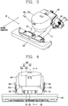
- FIG. 1 is a perspective view of a robot cleaner 100 according to the present invention
- FIG. 2 is a bottom view of the robot cleaner 100 of FIG. 1 .
- the robot cleaner 100 performs a function to clean a floor by sucking dust (including foreign materials) on the floor, while autonomously moving on a predetermined region.
- the robot cleaner 100 includes a cleaner body 101 for performing a moving function, a controller (not shown) and a moving unit 110.
- the cleaner body 101 is configured to accommodate components therein, and to move on a floor by the moving unit 110.
- a controller for controlling an operation of the robot cleaner 100, a battery (not shown) for supplying power to the robot cleaner 100, an obstacle sensor 103 for avoiding an obstacle while moving, a damper 104 for absorbing a shock when colliding with an obstacle, etc. may be accommodated in or mounted to the cleaner body 101.
- the moving unit 110 is configured to move (or rotate) the cleaner body 101 back and forth or right and left, and is provided with main wheels 111 and a supplementary wheel 112.
- the main wheels 111 are provided at two sides of the cleaner body 101, are configured to be rotatable to one direction or another direction according to a control signal.
- the main wheels 111 may be configured to be independently driven. For instance, each of the main wheels 111 may be driven by a different motor.
- Each of the main wheels 111 may be composed of wheels 111 a and 111 b having different radiuses with respect to a rotation shaft. Under such configuration, in a case where the main wheel 111 moves up on an obstacle such as a bump, at least one of the wheels 111 a and 111 b contacts the obstacle. This can prevent idling of the main wheel 111.
- the supplementary wheel 112 is configured to support the cleaner body 101 together with the main wheels 111, and to supplement movement of the cleaner body by the main wheels 111.
- the robot cleaner 100 is provided with its own cleaning function.
- the present invention provides the robot cleaner 100 of a new structure and arrangement, the robot cleaner 100 having an enhanced cleaning function by effectively separating dust from sucked air.
- FIG. 3 is a conceptual view illustrating main components inside the robot cleaner 100 of FIG. 1
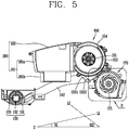
- FIG. 4 is a front view of the robot cleaner 100 of FIG. 3
- FIG. 5 is a sectional view taken along line 'A-A' in FIG. 4 .
- the robot cleaner 100 includes a driving unit 120, a suction unit 130, a first guiding member 141, a second guiding member 142, and a cyclone unit 150.
- the driving unit 120 is provided with a motor (not shown) mounted to the cleaner body 101 and generating a driving force.
- the motor is configured to generate a suction force for sucking dust-contained air on a floor, by rotating a first fan 171 and a second fan 172 to be explained later. It is noted that also only one fan can be used.
- the suction unit 130 is provided at a bottom portion of the cleaner body 101, and is configured to suck dust-contained air on a floor by the driving unit 120.
- the suction unit 130 may be arranged at a front side of the cleaner body 101, and may be detachably mounted to the cleaner body 101. Positions or directions are in relation to the orientation of the robot cleaner during normal operation.
- the suction unit 130 includes a suction opening 131, a roller 132 and a brush 133.
- the suction opening 131 may be formed to extend in a lengthwise direction of the suction unit 130.
- the roller 132 is rotatably installed at the suction opening 131, and the brush 133 is mounted to an outer circumferential surface of the roller 132.
- the brush 133 is configured to sweep up dust on a floor to the suction opening 131.
- the brush 133 may be formed of various materials including a fibrous material, an elastic material, etc.
- the first guiding member 141 and the second guiding member 142 may be provided between the suction unit 130 and the cyclone unit 150, thereby connecting the suction unit 130 and the cyclone unit 150 to each other.
- the first guiding member 141 and the second guiding member 142 are spaced from each other.
- One ends of the first and second guiding members 141 and 142 coupled to the suction unit 130 may be fixed to the cleaner body 101.
- Air sucked through the suction unit 130 is introduced into the cyclone unit 150 in a diverged manner, through the first and second guiding members 141 and 142.
- Such configuration is advantageous in that air sucking efficiency is more enhanced, than in a case where a single guiding member is provided.
- the first and second guiding members 141 and 142 may be disposed to be upward inclined toward the cyclone unit 150, so as to extend from the suction unit 130 toward the cyclone unit 150 (specifically, a first suction opening 150a and a second suction opening 150b), the cyclone unit 150 arranged at a rear upper side of the suction unit 130.
- the cyclone unit 150 may be provided with a cylindrical inner circumferential surface, and may be long-formed along one direction (X1). That is, the cyclone unit 150 may have an approximate cylindrical shape.
- the one direction (X1) may be a direction perpendicular to a moving direction of the robot cleaner 100.
- the cyclone unit 150 is configured to filter dust from air sucked thereto through the suction unit 130. More specifically, air sucked into the cyclone unit 150 is rotated along an inner circumferential surface of the cyclone unit 150. During such process, dust is collected to a dust box 160 communicated with a dust discharge opening 150e, and dust-filtered air is introduced into a first cyclone 151 and a second cyclone 152.
- the dust discharge opening 150e is formed at a front part of the cyclone unit 150.
- the dust discharge opening 150e may be formed between the first suction opening 150a and the second suction opening 150b (or between the first cyclone 151 and the second cyclone 152), i.e., at a central portion of the cyclone unit 150.
- dust included in air introduced into two sides of the cyclone unit 150 through the first and second suction openings 150a and 150b rotates along an inner circumferential surface of the cyclone unit 150, toward a central part from an end part of the cyclone unit 150. Then the dust is collected to the dust box 160 through the dust discharge opening 150e.
- the dust box 160 is connected to the cyclone unit 150, and is configured to collect dust filtered by the cyclone unit 150.
- the dust box 160 is disposed between the suction unit 130 and the cyclone unit 150.
- the dust box 160 is detachably mounted to the cyclone unit 150 so as to be separable from the cleaner body 101. Such structure will be explained in more detail.
- a cover 102 openably-coupled to the cleaner body 101 is open, the dust box 160 may be in a separable state by being exposed to outside.
- the dust box 160 may be configured to be exposed to outside, thereby forming appearance of the robot cleaner 100 together with the cleaner body 101. In this case, a user can check the amount of dust accumulated in the dust box 160 without opening the cover 102.
- the dust box 160 may include a dust box body 161 and a dust box cover 162.
- the dust box body 161 forms a space for collecting dust filtered by the cyclone unit 150, and the dust box cover 162 is coupled to the dust box body 161 so as to open and close an opening of the dust box body 161.
- the dust box cover 162 may be configured to open and close the opening of the dust box body 161, by being hinge-coupled to the dust box body 161.
- the dust discharge opening 150e may be provided at the dust box body 161. However, the present invention is not limited to this.
- the dust discharge opening 150e may be also formed at the dust box cover 162 according to a modified design.
- the dust box 160 connected to the cyclone unit 150 may be formed to have a predetermined depth, since the cyclone unit 150 is arranged at an upper side of the suction unit 130. For efficient spatial arrangement, at least part of the dust box 160 may be accommodated in a space between the first guiding member 141 and the second guiding member 142.
- the dust box body 161 includes a first portion 161 a and a second portion 161 b having different sectional areas.
- the first portion 161 a may be communicated with the dust discharge opening 150e, and at least part of the first portion 161 a may be disposed on the first and second guiding members 141 and 142. As shown in FIG. 4 , in this embodiment, two sides of the first portion 161 a are disposed on the first and second guiding members 141 and 142.
- the second portion 161 b is formed to extend to a lower side of the first portion 161a, and to have a smaller sectional area than the first portion 161 a. Accordingly, at least part of the second portion 161 is accommodated in a space between the first and second guiding members 141 and 142.
- the first and second guiding members 141 and 142 may be formed such that at least part thereof is bent to enclose the second portion 161 b at two sides.
- dust collected into the dust box 160 is firstly accumulated in the second portion 161 b.
- an inclined portion (not shown), inclined toward the second portion 161 b so that dust can move to the second portion 161 b, may be provided between the first portion 161 a and the second portion 161 b.
- the dust box cover 162 may be arranged to be inclined so that at least part thereof can face the dust discharge opening 150e. Under such structure, dust introduced into the dust box 160 through the dust discharge opening 150e can directly collide with the dust box cover 162 without being windblown, thereby being collected in the dust box body 161 (mainly, the second portion 161 b).
- a fan unit 170 may be connected to the cyclone unit 150, such that dust-filtered air is discharged to outside.
- the fan unit 170 is configured to generate a suction force by being driven by the driving unit 120, and to finally discharge clean air to outside.
- the fan unit 170 may be fixed to the cleaner body 101, and may be provided at a rear lower side of the cyclone unit 150.
- the cyclone unit 150 is coupled onto the fan unit 170 (specifically, a first communication member 173 and a second communication member 174), thereby being spaced from a bottom surface of the cleaner body 101.
- an arbitrary line (L1) which connects two ends of the first guiding member 141 or the second guiding member 142 to each other, has an inclination angle ( ⁇ 1), from a bottom surface (S) of the cleaner body 101.
- An arbitrary line (L2) which connects the cyclone unit 150 and the fan unit 170 to each other, has an inclination angle ( ⁇ 2), from the bottom surface (S) of the cleaner body 101.
- a volume of the dust box 160 may be variously changed.
- the fan unit 170 includes two fans.
- the fan unit 170 may also include only one fan for realizing the effects of the present invention.
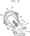
- FIG. 6 is a side sectional view illustrating the cyclone unit 150 and the fan unit 170 separated from the robot cleaner 100 of FIG. 3 .
- FIG. 7A is a perspective view of the cyclone unit 150 and the fan unit 170 of FIG. 6 .
- the FIG. 7B is a conceptual view illustrating a state where a second case 154 of the cyclone unit 150 of FIG. 7A has been removed.
- the cyclone unit 150 is provided with the first suction opening 150a communicated with the first guiding member 141, and the second suction opening 150b communicated with the second guiding member 142.
- the first suction opening 150a and the second suction opening 150b may be formed at two sides of the cyclone unit 150, such that air introduced into the cyclone unit 150 through the first suction opening 150a and the second suction opening 150b rotates along an inner circumferential surface of the cyclone unit 150, toward a central part from an end part of the cyclone unit 150.
- the cyclone unit 150 may further include a first suction guide 150a' and a second suction guide 150b' configured to guide air sucked to the cyclone unit 150 through the first suction opening 150a and the second suction opening 150b to an inner circumferential surface of the cyclone unit 150, respectively.
- the first suction guide 150a' is formed at the first suction opening 150a toward an inner circumferential surface of the cyclone unit 150
- the second suction guide 150b' is formed at the second suction opening 150b toward an inner circumferential surface of the cyclone unit 150.
- the cyclone unit 150 is provided therein with the first cyclone 151 and the second cyclone 152, such that dust-filtered air is introduced into the first cyclone 151 and the second cyclone 152.
- the first cyclone 151 has a structure that an air passing hole 151b is formed at a protruding member 151 a having an empty inner space
- the second cyclone 152 has a structure that an air passing hole 152b is formed at a protruding member 152a having an empty inner space. That is, dust cannot pass through the air passing holes 151b and 152b, whereas air can pass through the air passing holes 151b and 152b to thus be introduced into the inner spaces of the protruding members 151 a and 152a.
- the first cyclone 151 may be arranged close to the first suction opening 150a
- the second cyclone 152 may be arranged close to the second suction opening 150b .
- air sucked into the cyclone unit 150 through the first suction opening 150a is mainly introduced into the first cyclone 151
- air sucked into the cyclone unit 150 through the second suction opening 150b is mainly introduced into the second cyclone 152.
- dust can be efficiently filtered from the sucked air, and the dust-filtered air can be more efficiently discharged from the cyclone unit 150.
- the first and second cyclones 151 and 152 may be provided at two ends of the cyclone unit 150 in a facing manner.
- the first and second cyclones 151 and 152 may be formed to protrude from the same axis (X2).
- the axis (X2) may be perpendicular to a moving direction (forward or backward direction) of the robot cleaner 100.
- the axis (X2) may be identical to the aforementioned one direction (X1).
- the first and second cyclones 151 and 152 may be arranged at central regions of two end portions of the cyclone unit 150 so as to have a preset separating distance from an inner circumferential surface of the cyclone unit 150. Under such structure, dust can rotate along an inner circumferential surface of the cyclone unit 150, and dust-filtered air can be mainly introduced into the first and second cyclones 151 and 152.
- a cyclone unit 250 may be configured so that air which has passed through first and second suction openings (not shown) can be introduced toward a central part of the cyclone unit 250. Under such structure, air introduced into the cyclone unit 250 can easily rotate toward a central part of the cyclone unit 250 from an end part of the cyclone unit 250.
- the cyclone unit 250 is arranged so that a region for accommodating a first cyclone 251 and a region for accommodating a second cyclone 252 have a preset angle therebetween.
- the preset angle viewed from a front side may be 180° or less.
- the first and second suction openings may be formed toward a central part of the cyclone unit 250 such that air is introduced into the central part of the cyclone unit 250.
- the first and second suction guides aforementioned with reference to the aforementioned embodiment may be formed to extend toward the central part of the cyclone unit 250.
- the cyclone unit 150 may include a first case 153 and a second case 154.
- the first case 153 is provided with the first and second suction openings 150a and 150b and the first and second cyclones 151 and 152, and is configured to be coupled to the first and second guiding members 141 and 142.
- the second case 154 is provided with a dust discharge opening, and is openably coupled to the first case 153.
- the second case 154 may be hinge-coupled to the first case 153, and may be configured to open and close the first case 153 by being rotated.
- the cyclone unit 150 may further include a first discharge opening 150c and a second discharge opening (not shown) communicated with inner spaces of the first and second cyclones 151 and 152 so that dust-filtered air can be discharged. As shown, the first discharge opening 150c and the second discharge opening (not shown) may be provided at two sides of the cyclone unit 150.
- the fan unit 170 may be connected to each of the first discharge opening 150c and the second discharge opening (not shown), such that dust-filtered air is discharged to outside.
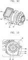
- FIG. 9A is a perspective view of the fan unit 170 shown in FIG. 6
- FIG. 9B is a conceptual view illustrating a state where a first communication member 173 has been removed from the fan unit 170 of FIG. 9A
- FIG. 9C is a conceptual view illustrating a state where a first fan cover 175 has been removed from the fan unit 170 of FIG. 9B
- FIG. 10 is an enlarged view of part 'B' shown in FIG. 5 .
- the fan unit 170 includes a first fan 171, a second fan 172, a first communication member 173 and a second communication member 174.
- the first and second fans 171 and 172 are configured to suck dust-filtered air and to discharge the air to outside while being rotated by the driving unit 120.
- Each of the first and second fans 171 and 172 may be formed as a volute fan.
- the driving unit 120 is disposed between the first and second fans 171 and 172, and the first and second fans 171 and 172 are driven to generate a suction force.
- the present invention is not limited to this. That is, an installation position of the driving unit 120 may be variable.
- the first communication member 173 is configured to connect the first discharge opening 150c of the cyclone unit 150 with the first fan 171, and thus to guide air introduced into the inner space of the first cyclone 151 into the first fan 171.
- the second communication member 174 is configured to connect the second discharge opening of the cyclone unit 150 with the second fan 172, and thus to guide air introduced into the inner space of the second cyclone 152 into the second fan 172.
- the first case 153 may be provided with the first discharge opening 150c and the second discharge opening (not shown), and may be coupled to each of the first and second communication members 173 and 174.
- a first coupling member 155 for coupling with the first communication member 173, and a second coupling member 156 for coupling with the second communication member 174 may be provided at two sides of the first case 153.
- each of the first and second coupling members 155 and 156 may include a hook and an elastic member. More specifically, the hooks are rotatably coupled to two sides of the first case 153, and are locked by the first and second communication members 173 and 174.
- the elastic members are configured to elastically press the hooks so that a locked state of the hooks to the first and second communication members 173 and 174 can be maintained.
- the first and second communication members 173 and 174 may be provided with locking protrusions 173a and 174a configured to lock the hooks so that the first case 153 can be prevented from being separated from the first and second communication members 173 and 174.
- Coupling of the first case 153 with the first and second communication members 173 and 174 is not limited to the above coupling. That is, the first case 153 may be coupled with the first and second communication members 173 and 174 in various manners without an additional coupling member, e.g., by using a locking structure or by bonding.
- Fine dust filters 173b and 174b configured to filter fine dust from dust-filtered air, may be mounted to the first and second communication members 173 and 174.
- the fine dust filters 173b and 174b HEPA filters may be used.
- the fine dust filters 173b and 174b may be configured to be exposed to outside when the cyclone unit 150 is separated from the first and second communication members 173 and 174.
- the fan unit 170 may further include a first fan cover 175 for accommodating the first fan 171 therein, and a second fan cover 176 for accommodating the second fan 172 therein.
- the first fan cover 175 is provided with a first air inlet 175a in a direction of a rotation shaft of the first fan 171, and is provided with a first air outlet 175b in a radius direction of the first fan 171.
- the second fan cover 176 is provided with a second air inlet (not shown) in a direction of a rotation shaft of the second fan 172, and is provided with a second air outlet (not shown) in a radius direction of the second fan 172.
- Dust-filtered air is introduced into the first fan cover 175 through the first air inlet 175a by a suction force due to rotation of the first fan 171. Then the air is moved to a side direction by rotation of the first fan 171 implemented as a volute fan, and is discharged out through the first air outlet 175b.
- Such mechanism may be equally applied to processes to suck and discharge air by rotation of the second fan 172.
- a preset gap may be maintained between an inner circumferential surface of the first fan cover 175 and an end portion of the first fan 171 disposed close to the first fan cover 175. Likewise, a preset gap may be maintained between an inner circumferential surface of the second fan cover 176 and an end portion of the second fan 172 disposed close to the second fan cover 176.
- the first fan cover 175 may be provided with a first exhaustion guide 175b' for guiding smooth exhaustion of dust-filtered air, and the second fan cover 176 may be provided with a second exhaustion guide (not shown). More specifically, the first exhaustion guide 175b' may extend from an inner circumferential surface of the first fan cover 175 toward the first air outlet 175b, in a rounded shape.
- a first exhaustion hole (not shown) corresponding to the first air outlet 175b, and a second exhaustion hole (not shown) corresponding to the second air outlet (not shown) may be formed at the cleaner body 101.
- a fine dust filter 175c may be mounted to at least one of the first fan cover 175 and the cleaner body 101, such that cleaner air is finally discharged to outside.
- an HEPA filter may be used as the fine dust filter 175c.
- the fine dust filter 175c is mounted to at least one of the first air outlet 175b and the first exhaustion hole in a covering manner, and is configured to filter fine dust from dust-filtered air. Likewise, the fine dust filter 175c may be mounted to at least one of the second fan cover 176 and the cleaner body 101.
- the robot cleaner according to the present invention can have the following advantages.
- a single cyclone unit is provided with therein a plurality of cyclones, dust can be effectively filtered from sucked air.
- a plurality of guiding members are provided to correspond to a plurality of cyclones, so that air sucked through a suction unit can be introduced into the cyclone unit after dust has been filtered from the air.
- a fan unit is configured so that air which has passed through the plurality of cyclones can be discharged to outside. Under such structure, dust can be more effectively filtered from sucked air, and dust-filtered air can be discharged to outside, thereby enhancing a cleaning function of the robot cleaner.
- the robot cleaner according to the present invention is provided with a suction guide for guiding sucked air to an inner circumferential surface of the cyclone unit, and the exhaustion guide extending from an inner circumferential surface of a fan cover toward an air outlet. Accordingly, the robot cleaner can reduce noise when sucking and discharging air.
- the cyclone unit having the plurality of cyclones is arranged at a rear upper side of the suction unit, and a plurality of connection members extend from the suction unit toward the cyclone unit with an inclination angle, for connection between the suction unit and the cyclone unit.
- the fan unit is provided at a rear lower side of the cyclone unit.
- the dust box can have a larger capacity within the restricted space.
Priority Applications (1)
| Application Number | Priority Date | Filing Date | Title |
|---|---|---|---|
| PL14199941T PL3000372T3 (pl) | 2014-09-24 | 2014-12-23 | Odkurzacz - robot |
Applications Claiming Priority (1)
| Application Number | Priority Date | Filing Date | Title |
|---|---|---|---|
| KR1020140127834A KR101622713B1 (ko) | 2014-09-24 | 2014-09-24 | 로봇 청소기 |
Publications (2)
| Publication Number | Publication Date |
|---|---|
| EP3000372A1 EP3000372A1 (en) | 2016-03-30 |
| EP3000372B1 true EP3000372B1 (en) | 2017-02-15 |
Family
ID=52282512
Family Applications (1)
| Application Number | Title | Priority Date | Filing Date |
|---|---|---|---|
| EP14199941.7A Active EP3000372B1 (en) | 2014-09-24 | 2014-12-23 | Robot cleaner |
Country Status (6)
| Country | Link |
|---|---|
| US (1) | US9504365B2 (ko) |
| EP (1) | EP3000372B1 (ko) |
| KR (1) | KR101622713B1 (ko) |
| CN (1) | CN105433858B (ko) |
| ES (1) | ES2623385T3 (ko) |
| PL (1) | PL3000372T3 (ko) |
Families Citing this family (10)
| Publication number | Priority date | Publication date | Assignee | Title |
|---|---|---|---|---|
| KR101660749B1 (ko) * | 2015-07-28 | 2016-10-10 | 엘지전자 주식회사 | 로봇 청소기 |
| KR101903022B1 (ko) | 2016-07-14 | 2018-10-01 | 엘지전자 주식회사 | 로봇 청소기 |
| FR3055790B1 (fr) * | 2016-09-13 | 2018-09-07 | Seb S.A. | Robot de nettoyage des sols |
| US10456002B2 (en) | 2016-12-22 | 2019-10-29 | Irobot Corporation | Cleaning bin for cleaning robot |
| US10595696B2 (en) | 2018-05-01 | 2020-03-24 | Sharkninja Operating Llc | Docking station for robotic cleaner |
| KR20210032482A (ko) | 2018-07-20 | 2021-03-24 | 샤크닌자 오퍼레이팅 엘엘씨 | 로봇 청소기 부스러기 제거 도킹 스테이션 |
| US11497366B2 (en) | 2019-01-25 | 2022-11-15 | Sharkninja Operating Llc | Cyclonic separator for a vacuum cleaner and a vacuum cleaner having the same |
| KR102091759B1 (ko) * | 2019-05-08 | 2020-03-20 | 엘지전자 주식회사 | 이동로봇 |
| KR102309309B1 (ko) * | 2020-02-25 | 2021-10-06 | 엘지전자 주식회사 | 청소기 |
| USD1011666S1 (en) * | 2021-11-04 | 2024-01-16 | Yunjing Intelligence Innovation (Shenzhen) Co., Ltd. | Drive module of robot cleaner |
Family Cites Families (10)
| Publication number | Priority date | Publication date | Assignee | Title |
|---|---|---|---|---|
| JPH0724643B2 (ja) * | 1992-10-26 | 1995-03-22 | 東京コスモス電機株式会社 | 還流式掃除機及び吸引式掃除機 |
| US6195835B1 (en) * | 1998-12-02 | 2001-03-06 | Samsung Kwangju Electronics Co., Ltd. | Vacuum cleaner having a cyclone dust collecting device |
| KR100377015B1 (ko) * | 2000-08-07 | 2003-03-26 | 삼성광주전자 주식회사 | 진공청소기의 사이클론 집진장치 |
| KR100778125B1 (ko) | 2005-12-19 | 2007-11-21 | 삼성광주전자 주식회사 | 콤팩트한 로봇청소기 |
| KR101292125B1 (ko) * | 2006-03-07 | 2013-08-09 | 삼성전자주식회사 | 로봇청소기 |
| ATE537744T1 (de) * | 2007-02-15 | 2012-01-15 | Hanool Robotics Corp | Reinigungsroboter mit abluftrückführungsfunktion |
| KR101455676B1 (ko) * | 2008-01-02 | 2014-10-30 | 삼성전자주식회사 | 듀얼 싸이클론 집진장치 및 이를 구비하는 청소기 |
| KR100959973B1 (ko) | 2008-04-16 | 2010-05-27 | 엘지전자 주식회사 | 진공 청소기의 먼지 분리 장치 |
| US8887349B2 (en) * | 2009-04-16 | 2014-11-18 | Lg Electronics Inc. | Vacuum cleaner |
| US9282867B2 (en) * | 2012-12-28 | 2016-03-15 | Irobot Corporation | Autonomous coverage robot |
-
2014
- 2014-09-24 KR KR1020140127834A patent/KR101622713B1/ko active IP Right Grant
- 2014-12-23 ES ES14199941.7T patent/ES2623385T3/es active Active
- 2014-12-23 PL PL14199941T patent/PL3000372T3/pl unknown
- 2014-12-23 EP EP14199941.7A patent/EP3000372B1/en active Active
-
2015
- 2015-06-22 US US14/745,830 patent/US9504365B2/en active Active
- 2015-07-14 CN CN201510412305.8A patent/CN105433858B/zh active Active
Non-Patent Citations (1)
| Title |
|---|
| None * |
Also Published As
| Publication number | Publication date |
|---|---|
| EP3000372A1 (en) | 2016-03-30 |
| US9504365B2 (en) | 2016-11-29 |
| CN105433858B (zh) | 2018-06-12 |
| CN105433858A (zh) | 2016-03-30 |
| PL3000372T3 (pl) | 2017-07-31 |
| KR20160035899A (ko) | 2016-04-01 |
| KR101622713B1 (ko) | 2016-05-19 |
| US20160081523A1 (en) | 2016-03-24 |
| ES2623385T3 (es) | 2017-07-11 |
Similar Documents
| Publication | Publication Date | Title |
|---|---|---|
| EP3000372B1 (en) | Robot cleaner | |
| EP3178361B1 (en) | Robot cleaner | |
| EP3031376B1 (en) | Mop module and robot cleaner having the same | |
| EP3028619B1 (en) | Robot cleaner | |
| CN113226142B (zh) | 机器人清洁器、站和清洁系统 | |
| US8667638B2 (en) | Robot cleaner | |
| EP3232892B1 (en) | Dust collector for vacuum cleaner | |
| KR102656583B1 (ko) | 로봇 청소기 | |
| EP2666399B1 (en) | Robot cleaner | |
| US9622633B2 (en) | Robot cleaner | |
| EP2253259A1 (en) | Electric cleaner and method of producing the same | |
| KR102367199B1 (ko) | 로봇 청소기 | |
| KR102297759B1 (ko) | 로봇 청소기 |
Legal Events
| Date | Code | Title | Description |
|---|---|---|---|
| PUAI | Public reference made under article 153(3) epc to a published international application that has entered the european phase |
Free format text: ORIGINAL CODE: 0009012 |
|
| AK | Designated contracting states |
Kind code of ref document: A1 Designated state(s): AL AT BE BG CH CY CZ DE DK EE ES FI FR GB GR HR HU IE IS IT LI LT LU LV MC MK MT NL NO PL PT RO RS SE SI SK SM TR |
|
| AX | Request for extension of the european patent |
Extension state: BA ME |
|
| 17P | Request for examination filed |
Effective date: 20160420 |
|
| RBV | Designated contracting states (corrected) |
Designated state(s): AL AT BE BG CH CY CZ DE DK EE ES FI FR GB GR HR HU IE IS IT LI LT LU LV MC MK MT NL NO PL PT RO RS SE SI SK SM TR |
|
| GRAP | Despatch of communication of intention to grant a patent |
Free format text: ORIGINAL CODE: EPIDOSNIGR1 |
|
| RIC1 | Information provided on ipc code assigned before grant |
Ipc: A47L 9/16 20060101ALI20160804BHEP Ipc: A47L 9/24 20060101AFI20160804BHEP Ipc: A47L 9/00 20060101ALI20160804BHEP Ipc: A47L 9/12 20060101ALI20160804BHEP Ipc: A47L 9/22 20060101ALI20160804BHEP |
|
| INTG | Intention to grant announced |
Effective date: 20160907 |
|
| RAP1 | Party data changed (applicant data changed or rights of an application transferred) |
Owner name: LG ELECTRONICS INC. |
|
| GRAS | Grant fee paid |
Free format text: ORIGINAL CODE: EPIDOSNIGR3 |
|
| GRAA | (expected) grant |
Free format text: ORIGINAL CODE: 0009210 |
|
| AK | Designated contracting states |
Kind code of ref document: B1 Designated state(s): AL AT BE BG CH CY CZ DE DK EE ES FI FR GB GR HR HU IE IS IT LI LT LU LV MC MK MT NL NO PL PT RO RS SE SI SK SM TR |
|
| REG | Reference to a national code |
Ref country code: GB Ref legal event code: FG4D Ref country code: CH Ref legal event code: EP |
|
| REG | Reference to a national code |
Ref country code: IE Ref legal event code: FG4D |
|
| REG | Reference to a national code |
Ref country code: AT Ref legal event code: REF Ref document number: 867430 Country of ref document: AT Kind code of ref document: T Effective date: 20170315 Ref country code: NL Ref legal event code: FP |
|
| REG | Reference to a national code |
Ref country code: DE Ref legal event code: R096 Ref document number: 602014006787 Country of ref document: DE |
|
| REG | Reference to a national code |
Ref country code: LT Ref legal event code: MG4D |
|
| REG | Reference to a national code |
Ref country code: ES Ref legal event code: FG2A Ref document number: 2623385 Country of ref document: ES Kind code of ref document: T3 Effective date: 20170711 |
|
| REG | Reference to a national code |
Ref country code: AT Ref legal event code: MK05 Ref document number: 867430 Country of ref document: AT Kind code of ref document: T Effective date: 20170215 |
|
| PG25 | Lapsed in a contracting state [announced via postgrant information from national office to epo] |
Ref country code: NO Free format text: LAPSE BECAUSE OF FAILURE TO SUBMIT A TRANSLATION OF THE DESCRIPTION OR TO PAY THE FEE WITHIN THE PRESCRIBED TIME-LIMIT Effective date: 20170515 Ref country code: GR Free format text: LAPSE BECAUSE OF FAILURE TO SUBMIT A TRANSLATION OF THE DESCRIPTION OR TO PAY THE FEE WITHIN THE PRESCRIBED TIME-LIMIT Effective date: 20170516 Ref country code: HR Free format text: LAPSE BECAUSE OF FAILURE TO SUBMIT A TRANSLATION OF THE DESCRIPTION OR TO PAY THE FEE WITHIN THE PRESCRIBED TIME-LIMIT Effective date: 20170215 Ref country code: LT Free format text: LAPSE BECAUSE OF FAILURE TO SUBMIT A TRANSLATION OF THE DESCRIPTION OR TO PAY THE FEE WITHIN THE PRESCRIBED TIME-LIMIT Effective date: 20170215 Ref country code: FI Free format text: LAPSE BECAUSE OF FAILURE TO SUBMIT A TRANSLATION OF THE DESCRIPTION OR TO PAY THE FEE WITHIN THE PRESCRIBED TIME-LIMIT Effective date: 20170215 |
|
| PG25 | Lapsed in a contracting state [announced via postgrant information from national office to epo] |
Ref country code: BG Free format text: LAPSE BECAUSE OF FAILURE TO SUBMIT A TRANSLATION OF THE DESCRIPTION OR TO PAY THE FEE WITHIN THE PRESCRIBED TIME-LIMIT Effective date: 20170515 Ref country code: PT Free format text: LAPSE BECAUSE OF FAILURE TO SUBMIT A TRANSLATION OF THE DESCRIPTION OR TO PAY THE FEE WITHIN THE PRESCRIBED TIME-LIMIT Effective date: 20170615 Ref country code: RS Free format text: LAPSE BECAUSE OF FAILURE TO SUBMIT A TRANSLATION OF THE DESCRIPTION OR TO PAY THE FEE WITHIN THE PRESCRIBED TIME-LIMIT Effective date: 20170215 Ref country code: AT Free format text: LAPSE BECAUSE OF FAILURE TO SUBMIT A TRANSLATION OF THE DESCRIPTION OR TO PAY THE FEE WITHIN THE PRESCRIBED TIME-LIMIT Effective date: 20170215 Ref country code: LV Free format text: LAPSE BECAUSE OF FAILURE TO SUBMIT A TRANSLATION OF THE DESCRIPTION OR TO PAY THE FEE WITHIN THE PRESCRIBED TIME-LIMIT Effective date: 20170215 Ref country code: SE Free format text: LAPSE BECAUSE OF FAILURE TO SUBMIT A TRANSLATION OF THE DESCRIPTION OR TO PAY THE FEE WITHIN THE PRESCRIBED TIME-LIMIT Effective date: 20170215 |
|
| PG25 | Lapsed in a contracting state [announced via postgrant information from national office to epo] |
Ref country code: CZ Free format text: LAPSE BECAUSE OF FAILURE TO SUBMIT A TRANSLATION OF THE DESCRIPTION OR TO PAY THE FEE WITHIN THE PRESCRIBED TIME-LIMIT Effective date: 20170215 Ref country code: RO Free format text: LAPSE BECAUSE OF FAILURE TO SUBMIT A TRANSLATION OF THE DESCRIPTION OR TO PAY THE FEE WITHIN THE PRESCRIBED TIME-LIMIT Effective date: 20170215 Ref country code: SK Free format text: LAPSE BECAUSE OF FAILURE TO SUBMIT A TRANSLATION OF THE DESCRIPTION OR TO PAY THE FEE WITHIN THE PRESCRIBED TIME-LIMIT Effective date: 20170215 Ref country code: EE Free format text: LAPSE BECAUSE OF FAILURE TO SUBMIT A TRANSLATION OF THE DESCRIPTION OR TO PAY THE FEE WITHIN THE PRESCRIBED TIME-LIMIT Effective date: 20170215 |
|
| REG | Reference to a national code |
Ref country code: FR Ref legal event code: PLFP Year of fee payment: 4 |
|
| REG | Reference to a national code |
Ref country code: DE Ref legal event code: R097 Ref document number: 602014006787 Country of ref document: DE |
|
| PG25 | Lapsed in a contracting state [announced via postgrant information from national office to epo] |
Ref country code: DK Free format text: LAPSE BECAUSE OF FAILURE TO SUBMIT A TRANSLATION OF THE DESCRIPTION OR TO PAY THE FEE WITHIN THE PRESCRIBED TIME-LIMIT Effective date: 20170215 Ref country code: SM Free format text: LAPSE BECAUSE OF FAILURE TO SUBMIT A TRANSLATION OF THE DESCRIPTION OR TO PAY THE FEE WITHIN THE PRESCRIBED TIME-LIMIT Effective date: 20170215 |
|
| PLBE | No opposition filed within time limit |
Free format text: ORIGINAL CODE: 0009261 |
|
| STAA | Information on the status of an ep patent application or granted ep patent |
Free format text: STATUS: NO OPPOSITION FILED WITHIN TIME LIMIT |
|
| 26N | No opposition filed |
Effective date: 20171116 |
|
| PG25 | Lapsed in a contracting state [announced via postgrant information from national office to epo] |
Ref country code: SI Free format text: LAPSE BECAUSE OF FAILURE TO SUBMIT A TRANSLATION OF THE DESCRIPTION OR TO PAY THE FEE WITHIN THE PRESCRIBED TIME-LIMIT Effective date: 20170215 |
|
| REG | Reference to a national code |
Ref country code: CH Ref legal event code: PL |
|
| REG | Reference to a national code |
Ref country code: IE Ref legal event code: MM4A |
|
| PG25 | Lapsed in a contracting state [announced via postgrant information from national office to epo] |
Ref country code: MT Free format text: LAPSE BECAUSE OF NON-PAYMENT OF DUE FEES Effective date: 20171223 Ref country code: LU Free format text: LAPSE BECAUSE OF NON-PAYMENT OF DUE FEES Effective date: 20171223 |
|
| REG | Reference to a national code |
Ref country code: BE Ref legal event code: MM Effective date: 20171231 |
|
| PG25 | Lapsed in a contracting state [announced via postgrant information from national office to epo] |
Ref country code: IE Free format text: LAPSE BECAUSE OF NON-PAYMENT OF DUE FEES Effective date: 20171223 |
|
| REG | Reference to a national code |
Ref country code: FR Ref legal event code: PLFP Year of fee payment: 5 |
|
| PG25 | Lapsed in a contracting state [announced via postgrant information from national office to epo] |
Ref country code: CH Free format text: LAPSE BECAUSE OF NON-PAYMENT OF DUE FEES Effective date: 20171231 Ref country code: LI Free format text: LAPSE BECAUSE OF NON-PAYMENT OF DUE FEES Effective date: 20171231 Ref country code: BE Free format text: LAPSE BECAUSE OF NON-PAYMENT OF DUE FEES Effective date: 20171231 |
|
| PG25 | Lapsed in a contracting state [announced via postgrant information from national office to epo] |
Ref country code: MC Free format text: LAPSE BECAUSE OF FAILURE TO SUBMIT A TRANSLATION OF THE DESCRIPTION OR TO PAY THE FEE WITHIN THE PRESCRIBED TIME-LIMIT Effective date: 20170215 Ref country code: HU Free format text: LAPSE BECAUSE OF FAILURE TO SUBMIT A TRANSLATION OF THE DESCRIPTION OR TO PAY THE FEE WITHIN THE PRESCRIBED TIME-LIMIT; INVALID AB INITIO Effective date: 20141223 |
|
| PG25 | Lapsed in a contracting state [announced via postgrant information from national office to epo] |
Ref country code: CY Free format text: LAPSE BECAUSE OF FAILURE TO SUBMIT A TRANSLATION OF THE DESCRIPTION OR TO PAY THE FEE WITHIN THE PRESCRIBED TIME-LIMIT Effective date: 20170215 |
|
| PG25 | Lapsed in a contracting state [announced via postgrant information from national office to epo] |
Ref country code: MK Free format text: LAPSE BECAUSE OF FAILURE TO SUBMIT A TRANSLATION OF THE DESCRIPTION OR TO PAY THE FEE WITHIN THE PRESCRIBED TIME-LIMIT Effective date: 20170215 |
|
| PGFP | Annual fee paid to national office [announced via postgrant information from national office to epo] |
Ref country code: NL Payment date: 20191106 Year of fee payment: 6 |
|
| PGFP | Annual fee paid to national office [announced via postgrant information from national office to epo] |
Ref country code: FR Payment date: 20191107 Year of fee payment: 6 Ref country code: PL Payment date: 20191106 Year of fee payment: 6 |
|
| PG25 | Lapsed in a contracting state [announced via postgrant information from national office to epo] |
Ref country code: TR Free format text: LAPSE BECAUSE OF FAILURE TO SUBMIT A TRANSLATION OF THE DESCRIPTION OR TO PAY THE FEE WITHIN THE PRESCRIBED TIME-LIMIT Effective date: 20170215 |
|
| PGFP | Annual fee paid to national office [announced via postgrant information from national office to epo] |
Ref country code: ES Payment date: 20200113 Year of fee payment: 6 |
|
| PG25 | Lapsed in a contracting state [announced via postgrant information from national office to epo] |
Ref country code: IS Free format text: LAPSE BECAUSE OF FAILURE TO SUBMIT A TRANSLATION OF THE DESCRIPTION OR TO PAY THE FEE WITHIN THE PRESCRIBED TIME-LIMIT Effective date: 20170615 Ref country code: AL Free format text: LAPSE BECAUSE OF FAILURE TO SUBMIT A TRANSLATION OF THE DESCRIPTION OR TO PAY THE FEE WITHIN THE PRESCRIBED TIME-LIMIT Effective date: 20170215 |
|
| REG | Reference to a national code |
Ref country code: NL Ref legal event code: MM Effective date: 20210101 |
|
| PG25 | Lapsed in a contracting state [announced via postgrant information from national office to epo] |
Ref country code: NL Free format text: LAPSE BECAUSE OF NON-PAYMENT OF DUE FEES Effective date: 20210101 |
|
| PG25 | Lapsed in a contracting state [announced via postgrant information from national office to epo] |
Ref country code: FR Free format text: LAPSE BECAUSE OF NON-PAYMENT OF DUE FEES Effective date: 20201231 |
|
| REG | Reference to a national code |
Ref country code: ES Ref legal event code: FD2A Effective date: 20220222 |
|
| PG25 | Lapsed in a contracting state [announced via postgrant information from national office to epo] |
Ref country code: ES Free format text: LAPSE BECAUSE OF NON-PAYMENT OF DUE FEES Effective date: 20201224 |
|
| PG25 | Lapsed in a contracting state [announced via postgrant information from national office to epo] |
Ref country code: PL Free format text: LAPSE BECAUSE OF NON-PAYMENT OF DUE FEES Effective date: 20201223 |
|
| PGFP | Annual fee paid to national office [announced via postgrant information from national office to epo] |
Ref country code: GB Payment date: 20231106 Year of fee payment: 10 |
|
| PGFP | Annual fee paid to national office [announced via postgrant information from national office to epo] |
Ref country code: IT Payment date: 20231107 Year of fee payment: 10 Ref country code: DE Payment date: 20231106 Year of fee payment: 10 |