EP3000280B1 - Kommunikationsvorrichtung, vorrichtung, system, verfahren und computerimplementierbares anweisungsprodukt - Google Patents
Kommunikationsvorrichtung, vorrichtung, system, verfahren und computerimplementierbares anweisungsprodukt Download PDFInfo
- Publication number
- EP3000280B1 EP3000280B1 EP14800957.4A EP14800957A EP3000280B1 EP 3000280 B1 EP3000280 B1 EP 3000280B1 EP 14800957 A EP14800957 A EP 14800957A EP 3000280 B1 EP3000280 B1 EP 3000280B1
- Authority
- EP
- European Patent Office
- Prior art keywords
- base station
- mme
- communication device
- mtc device
- data
- Prior art date
- Legal status (The legal status is an assumption and is not a legal conclusion. Google has not performed a legal analysis and makes no representation as to the accuracy of the status listed.)
- Active
Links
Images

Classifications
-
- H—ELECTRICITY
- H04—ELECTRIC COMMUNICATION TECHNIQUE
- H04W—WIRELESS COMMUNICATION NETWORKS
- H04W76/00—Connection management
- H04W76/20—Manipulation of established connections
- H04W76/25—Maintenance of established connections
-
- H—ELECTRICITY
- H04—ELECTRIC COMMUNICATION TECHNIQUE
- H04W—WIRELESS COMMUNICATION NETWORKS
- H04W4/00—Services specially adapted for wireless communication networks; Facilities therefor
- H04W4/70—Services for machine-to-machine communication [M2M] or machine type communication [MTC]
-
- H—ELECTRICITY
- H04—ELECTRIC COMMUNICATION TECHNIQUE
- H04W—WIRELESS COMMUNICATION NETWORKS
- H04W76/00—Connection management
- H04W76/30—Connection release
- H04W76/34—Selective release of ongoing connections
Definitions
- the present invention relates to a communications system.
- the invention has particular but not exclusive relevance to wireless communications systems and devices thereof operating according to the 3rd Generation Partnership Project (3GPP) standards or equivalents or derivatives thereof.
- the invention has particular although not exclusive relevance to the provision of assistance information by Machine-Type Communications devices.
- LTE Long Term Evolution
- EPC Evolved Packet Core
- E-UTRAN Evolved UMTS Terrestrial Radio Access Network
- a NodeB or an eNB in LTE
- HSS home subscriber server
- MME mobility management entity
- the MME communicates with the communication devices using non-access stratum (NAS) protocol messages.
- NAS non-access stratum
- Communications devices might be, for example, mobile communications devices such as mobile telephones, smartphones, user equipment, personal digital assistants, laptop/tablet computers, web browsers, e-book readers and the like. Such mobile (or even generally stationary) devices are typically operated by a user.
- MTC Machine-Type Communications
- M2M Machine-to-Machine
- 3GPP standards also make it possible to connect Machine-Type Communications (MTC) devices (sometimes also referred to as Machine-to-Machine (M2M) communications devices) to the network, which typically comprise automated equipment, such as various measuring equipment, telemetry equipment, monitoring systems, tracking and tracing devices, in-vehicle safety systems, vehicle maintenance systems, road sensors, digital billboards, point of sale (POS) terminals, remote control systems and the like.
- MTC Machine-Type Communications
- M2M Machine-to-Machine
- MTC devices can be implemented as a part of a (generally) stationary apparatus such as vending machines, roadside sensors, POS terminals, although some MTC devices can be embedded in non-stationary apparatus (e.g. vehicles) or attached to animals or persons to be monitored/tracked.
- a stationary apparatus such as vending machines, roadside sensors, POS terminals
- MTC devices can be embedded in non-stationary apparatus (e.g. vehicles) or attached to animals or persons to be monitored/tracked.
- the present application refers to MTC devices in the description but it will be appreciated that the technology described can be implemented on any communications devices (mobile and/or generally stationary) that can connect to a communications network for sending/receiving data, regardless whether such communications devices are controlled by human input or software instructions stored in memory.
- the term 'MTC device' is intended to cover any communications device implementing MTC functionality, such as mobile telephones / user equipment (UE) running an MTC application.
- a Radio Resource Control (RRC) connection needs to be established between an MTC device and the radio access network (RAN), i.e. a base station of that RAN currently serving the MTC device.
- RAN radio access network
- an RRC connection for a particular MTC device is usually released by the RAN/base station due to inactivity of the MTC device.
- an existing RRC connection may also be released due to a communication failure, authentication error, and/or the like.
- An RRC connection may also be released upon a request from a core network entity (e.g. the MME) and/or the MTC device itself (e.g. when it is being switched off).
- Inactivity of a communications device is determined by the serving base station at the expiry of a so called 'user inactivity' timer, when the base station releases the RRC connection for the inactive communications device.
- the base station Upon expiry of the user inactivity timer, the base station also notifies the core network about the release of the RRC connection using a so-called UE context release procedure, which is described in more detail in section 5.3.5 of the 3GPP TS23.401 standards specification.
- the base station runs a user inactivity timer (per RRC connection) during the existence of an RRC connection between the base station and the MTC device. Whenever the MTC device sends or receives data, the base station re-starts the user inactivity timer associated with that MTC device (i.e. the RRC connection used by the MTC device). When the user inactivity timer expires (i.e. it reaches a predefined value or it reaches zero if counting down from the predefined value), the base station initiates the RRC connection release procedure referred to above.
- MTC devices connect to the network whenever they have data to send to or receive from a remote 'machine' (e.g. a server) or user.
- MTC devices use communication protocols and standards that are optimised for mobile telephones or similar items of user equipment (UEs).
- UEs user equipment
- MTC devices once deployed, typically operate without requiring human supervision or interaction, and follow software instructions stored in an internal memory. MTC devices might also remain stationary and/or inactive for a long period of time.
- the specific network requirements to support MTC devices have been dealt with in the 3GPP TS 22.368 standard.
- MTC devices can benefit from a so-called 'small data transmissions' functionality, intended for the sending and/or receiving of small amounts of data (typically in the order of 1K (1024) octets of data).
- the system supports transmissions of small amounts of data with minimal impact on e.g. signalling overhead, network resources, and delay for reallocation of resources, regardless whether or not the MTC device is attached to the network before transmitting data.
- the network counts the number of small data transmissions per subscription e.g. for charging or statistical purposes. This allows charging and accounting of small data transmissions between network operators on a bulk basis.
- MTC devices One of the key issues is the efficiency of small data transmissions (including keep-alive messages) by MTC devices. It has been suggested that in case of mobile originated small data transmissions, instead of using a base station initiated RRC connection release procedure (e.g. inactivity timer run by the base station), the MME may control the RRC connection release.
- a base station initiated RRC connection release procedure e.g. inactivity timer run by the base station
- the MME uses knowledge of the subscriber to determine whether to proceed with the full UE triggered Service Request procedure, or, to immediately release the RRC connection, or to wait for some time (e.g. to see if a downlink IP packet causes the S-GW to send a Downlink Data notification to the MME)".
- This MME centric approach may be applied in case of mobile originated (MO) small data transmissions.
- the term 'Service Request' procedure as used herein includes, for example, the exchange of keep-alive messages and/or small data transmissions by the MTC device.
- the MME may decide, based on the information available to it, not to release a particular RRC connection even if the MTC device does not require this RRC connection anymore (e.g.
- the RRC connection may be maintained until expiry of the user inactivity timer at the base station (or even longer if the base station relies on the MME to release the RRC connection). This is also wasteful of the network resources.
- the MTC device can request its serving base station to release the RRC connection.
- the MTC device typically sends an Internet Protocol (IP) packet to the MME as an acknowledgement.
- IP Internet Protocol
- the IP packet is sent in an encrypted information element (IE) using NAS signalling included in an uplink information transfer message transmitted to the base station.
- the base station forwards the NAS signalling to the MME.
- the MME decrypts the IE, and also controls termination of the requesting MTC device's connection in the core network, e.g. by terminating a corresponding bearer at a gateway serving entity serving the MTC device (i.e. the so called serving gateway or S-GW).
- the request for the base station to release the RRC connection may be added as an optional IE in the uplink information transfer message sent from the MTC device to the base station.
- the optional release indication from the MTC device to its serving base station also does not cover all possible MT scenarios and it does not address the issues associated with the MME centric control suggested for MO small data transmissions.
- preferred embodiments of the present invention aim to provide methods and apparatus which address or at least partially deal with one or more of the above needs.
- WO 2009/121023 A1 discloses techniques for signaling whether or not a radio resource control (RRC) connection should be maintained.
- the signaling may be provided, for example, in existing NAS transport messages, or in separate messages.
- the signaling may be provided in the uplink and/or downlink direction.
- the invention provides a communication device, a base station, a Mobility Management Entity, corresponding methods, and computer program products as disclosed in the appended independent claims.
- Optional, but advantageous features are disclosed in the appended dependent claims.
- a communications device for providing information to a network entity for use in determining whether a radio bearer should be maintained or released, the communications device comprising: means for establishing the radio bearer via a base station of a communications system for sending or receiving data; means for sending or receiving data using the established radio bearer; means for providing to the network entity information configured to indicate a potential for future data to be sent or received by said communications device for use, by the network entity, in determining whether the radio bearer should be maintained or released accordingly.
- Said information configured to indicate a potential for future data to be sent or received by said communications device may comprise information configured to indicate whether or not any further data is to be sent or received by said communications device.
- Said information configured to indicate a potential for future data to be sent or received by said communications device may comprise information configured to indicate whether or not a user-plane connection is required for said communications device to be able to send or receive said future data.
- a communications device for providing information to a network entity for use in determining whether a radio bearer should be maintained or released, the communications device comprising: means for establishing the radio bearer via a base station of a communications system for sending or receiving data; means for sending or receiving data using the established radio bearer; means for determining at least one of: i) whether or not any further data is to be sent or received by said communications device; and ii) whether or not a user-plane connection is required for said communications device; and means for providing to the network entity information identifying a result of said determination for use, by the network entity, in determining whether the radio bearer should be maintained or released accordingly.
- the means for sending or receiving data may be operable to send or receive said data as a data packet in a payload of a control plane message.
- the means for sending or receiving data may be operable to send or receive said data as a data packet in a payload of a radio resource control (RRC) message.
- RRC radio resource control
- the means for sending or receiving data may be operable to send said data as a data packet in a payload of an uplink information transfer message or receive said data as a data packet in a payload of a downlink information transfer message.
- the means for sending or receiving data may also be operable to send or receive said data as a data packet in a payload of an RRC connection setup complete message.
- the information providing means may be operable to provide said information identifying a result of said determination to said network entity as part of a procedure for establishing said radio bearer.
- the determining means may determine that no further data is to be sent or received by said communications device, in which case said information identifying a result of said determination may comprise an indication that no further data is to be sent or received by said communications device.
- the determining means may determine that further data is to be sent or received by said communications device, in which case said information identifying a result of said determination may comprise an indication that further data is to be sent or received by said communications device.
- the further data may comprise data to be sent in response to data received by said communications device.
- the further data may also comprise data requiring establishment of a user plane connection for said communications device.
- the providing means may be operable to provide said information identifying a result of said determination to said network entity by sending at least one RRC message to said base station.
- the providing means may be operable to send said at least one RRC message as part of an RRC connection establishment procedure.
- the providing means may be operable to provide said information identifying a result of said determination using at least one information element in said at least one RRC message.
- the at least one RRC message may include at least one non-access stratum (NAS) message.
- the providing means may be operable to provide said information identifying a result of said determination using said at least one NAS message.
- the means for sending or receiving data may be operable to send said data as a data packet in a payload of said at least one RRC message in which said information identifying a result of said determination is provided to said network entity.
- the data packet may require a response to be received at said communications device, in which case said information identifying a result of said determination may indicate that no further data is to be sent or received by said communications device after receipt of said response.
- the data packet may comprise data sent in response to data received by said communications device, in which case wherein said information identifying a result of said determination may indicate that said communications device expects no further data to be sent or received after sending said data packet.
- the providing means may be operable to send said information identifying a result of said determination to said base station.
- the providing means may be operable to send said information identifying a result of said determination to a core network entity.
- the providing means may be operable to send said information identifying a result of said determination to said base station via said core network entity.
- the communications device may comprise at least one of a machine-type communications device, a mobile telephone, and user equipment operating in accordance with long term evolution (LTE) standards.
- LTE long term evolution
- an apparatus for managing a radio bearer for a communications device comprising: means for communicating data with said communications device using a radio bearer; means for obtaining information from said communications device, said information indicating, for the communications device, at least one of: i) whether or not any further data is to be sent or received by said communications device; and ii) whether or not a user-plane connection is required by said communications device; means for determining, from said obtained information, whether the radio bearer should be maintained or released; and means for maintaining said radio bearer in dependence of said determination.
- the data communicating means may be operable to send or receive said data as a data packet in a payload of a control plane message.
- the data communicating means may be operable to send or receive said data as a data packet in a payload of a radio resource control (RRC) message.
- RRC radio resource control
- the data communicating means may be operable to send said data as a data packet in a payload of a downlink information transfer message or receive said data as a data packet in a payload of an uplink information transfer message.
- the data communicating means may also be operable to receive said data as a data packet in a payload of an RRC connection setup complete message.
- the information obtaining means may be operable to obtain said information from said communications device as part of a procedure for establishing said radio bearer.
- the information may comprise an indication that no further data is to be sent or received by said communications device.
- the information may comprise an indication that further data is to be sent or received by said communications device.
- the further data may comprise data to be received, by said communications device, in response to data sent by said communications device.
- the further data may also comprise data requiring establishment of a user plane connection for said communications device.
- the obtaining means may be operable to obtain said information from said communications device by receiving at least one RRC message at said base station.
- the obtaining means may be operable to receive said at least one RRC message as part of an RRC connection establishment procedure for said mobile communications device.
- the obtaining means may be operable to obtain said information from at least one information element in said at least one RRC message.
- the at least one RRC message may include at least one non-access stratum (NAS) message.
- the obtaining means may be operable to obtain said information from said at least one NAS message.
- the data communicating means may be operable to receive said data as a data packet in a payload of said at least one RRC message in which said information is provided by said communications device.
- the data packet may require a response to be received at said communications device, in which case said obtained information may indicate that no further data is to be sent or received by said communications device after receipt of said response.
- the data packet may comprise data sent in response to data previously received by said communications device, in which case said obtained information may indicate that no further data is to be sent or received by said communications device after sending said response.
- the base station may comprise said obtaining means.
- the obtaining means may be operable to provide said obtained information to a core network entity.
- the maintaining means may be operable to i) maintain said radio bearer if said information indicates that further data is to be sent or received by said communications device and ii) release said radio bearer if said obtained information indicates that no further data is to be sent or received by said communications device.
- the maintaining means may be operable to request said communications device to establish a user-plane connection if said obtained information indicates that a user-plane connection is required by said communications device.
- the maintaining means may be operable to request said communications device to release said radio bearer if said obtained information indicates that no further data is to be sent or received by said communications device.
- the apparatus may comprise at least one of a base station and a mobility management entity operating in accordance with long term evolution (LTE) standards.
- LTE long term evolution
- a communications device for providing information to a network entity for use in determining whether a radio bearer should be maintained or released
- the communications device comprising a processor and a transceiver
- the processor is configured to establish the radio bearer via a base station of a communications system for sending or receiving data and the transceiver is configured to send or receive data using the established radio bearer.
- the processor is configured to determine at least one of: i) whether or not any further data is to be sent or received by said communications device and ii) whether or not a user-plane connection is required for said communications device; and to provide to the network entity information identifying a result of said determination for use, by the network entity, in determining whether the radio bearer should be maintained or released accordingly.
- an apparatus for managing a radio bearer for a communications device comprising a processor and a transceiver.
- the transceiver is configured to communicate data with said communications device using a radio bearer.
- the processor is configured to: obtain information from said communications device, said information indicating, for the communications device, at least one of: i) whether or not any further data is to be sent or received by said communications device and ii) whether or not a user-plane connection is required by said communications device; and determine, from said obtained information, whether the radio bearer should be maintained or released; and maintain said radio bearer in dependence of said determination.
- Also disclosed are corresponding methods and a system comprising the above communications device, the above base station, and the above mobility management entity.
- a computer program product comprising computer implementable instructions for causing a programmable computer device to become configured as a communications device, the base station, or the mobility management entity as described above.
- the computer software products may be provided on a carrier signal or on a recording medium, such as a CD, DVD or the like.
- the present invention it is possible to provide an improved management of a connection release in case of small data transmissions by a MTC device, and result in a more optimal usage of the overall resources of a communication system.
- Fig. 1 schematically illustrates a telecommunications network 1 in which MTC devices 2, mobile telephones 3, and other communications devices (not shown) can communicate with each other or MTC service providers (e.g. an MTC server) via a base station 5 and a core network 7 using an E-UTRA radio access technology (RAT).
- MTC service providers e.g. an MTC server
- RAT E-UTRA radio access technology
- the base station 5 is connected to the core network 7 via an S1 interface and to other base stations via an X2 interface (not shown).
- the core network 7 includes a gateway 8 for connecting to other networks, such as the Internet and/or to servers hosted outside the core network 7. It will be appreciated that the functionalities of the gateway 8 may be split between two logical (and/or physical) entities.
- the gateway functionality for connecting the base station 5 (hence the MTC devices 2 and the mobile telephones 3) to the core network 7 is carried out by a so-called serving gateway (S-GW) entity whereas the gateway functionality for connecting to other (external) networks is carried out by a so-called a packet data network (PDN) gateway, or simply P-GW, entity.
- S-GW serving gateway
- PDN packet data network
- a mobility management entity (MME) 9 is the network node responsible for keeping track of the locations of the mobile communication devices (e.g. mobile telephones 3 and the MTC devices 2) within the communications network 1.
- the MME 9 stores an identifier of the mobile communication devices' last known cell (or tracking area) so that they can be notified when there is an incoming (voice or data) call for them and that a communication path is set up via the base station 5 currently serving the particular mobile communication device.
- a home subscriber server (HSS) 10 stores subscription related information and control parameters specific for each communications device (e.g. the MTC devices 2 and the mobile telephones 3).
- the HSS 10 also stores information identifying which ones of the communications devices are configured as machine-type communication devices (e.g. the MTC devices 2 and/or a mobile telephone 3 when it is running an MTC client) and provides this information to the other network entities when needed.
- the MTC devices 2 and mobile telephones 3 establish an RRC connection with the base station 5 in order to be able to communicate with other devices via that base station 5 (and the core network 7).
- the MTC devices 2 support the small data transmission functionality so that their communications with other devices can be carried out in an efficient manner and with minimal network impact.
- the MTC devices 2 shown in Fig. 1 are also configured to provide assistance information to the MME 9 in order to indicate any further expected communications involving the MTC devices 2.
- the MME 9 may thus beneficially use the assistance information provided by each MTC device 2 in its determination whether or not to terminate the RRC connection (and possibly the S1 connection) for that particular MTC device 2.
- an MTC device 2 can provide at least one of the following types of assistance information:
- the MME 9 can beneficially instigate the release of the RRC and/ or S1 connection immediately.
- response data i.e. an acknowledgment
- the MME 9 maintains the RRC and S1 connections for the MTC device 2 and waits for the response data.
- the MME 9 can beneficially instigate the release the RRC and/or S1 connection for the MTC device 2 after receipt of the response data, e.g. without the MTC device 2 having to send an indication described in point i) above.
- the MME 9 may also wait for further assistance information and/or may take into account other information available to it before instigating the release of the RRC and/or S1 connection.
- iii) Information indicating that user-plane establishment is expected/needed If this indication is given by the MTC device 2, the MME 9 maintains the RRC/S 1 connection for the MTC device 2. In this case, the MME 9 can beneficially trigger a full service request for the establishment of the user-plane for the given MTC device 2. In this case, the MME 9 may wait for further assistance information (such as in point i) or ii) above) before instigating the release of the RRC and/or S1 connection for the MTC device 2.
- the provision of assistance information from the MTC device 2 to the MME 9 is achieved using NAS signalling.
- the NAS signalling carrying the assistance information can be embedded in any suitable RRC message exchanged between the MTC device 2 and the base station 5 so that it can be transmitted to the MME 9 regardless whether the MTC device 2 is involved in a mobile originated or mobile terminated small data transmission (and/or any other communication, such as regular data transmissions).
- the MTC device 2 includes any assistance information in an information element in the form of a preference indication (e.g. a 'release preference indication' IE) which may be added to the NAS signalling message or the RRC message carrying the NAS signalling message (or both).
- a preference indication e.g. a 'release preference indication' IE
- the release preference indication IE is included in the RRC message (i.e. the base station 5 can also read the release preference indication IE)
- the base station 5 can decide whether or not to release the RRC/S1 connection for that MTC device 2 in accordance with the received preference indication.
- the MME 9 when the MME 9 receives the assistance information, and decides to instigate the release of the RRC/S 1 connection for the MTC device 2, it informs the base station 5 accordingly, which proceeds to release the applicable RRC/S1 connection.
- the provision of the MTC device's 2 release preference (which takes into account any expected communication for/by that MTC device 2) can improve the decision making process at the MME 9 (or the base station 5). Since the release preference is based on information (expected communication) that may not be available to the network entity controlling the RRC/S1 connection, the provision of such assistance information by the MTC device 2 can result in a more optimal usage of the overall resources of the communication system 1. For example, the MTC devices 2 providing their release preference to the MME 9 and/or the base station 5 may not be required to send any keep-alive messages (or they may be required to send fewer keep-alive messages than other communication devices) in order to maintain an RRC connection with their serving base station 5.
- Fig. 2 is a block diagram illustrating the main components of the MTC device 2 shown in Fig. 1 .
- the MTC device 2 has a transceiver circuit 31 that is operable to transmit signals to and to receive signals from a base station 5 via one or more antenna 33.
- the MTC device 2 has a controller 37 to control the operation of the mobile device 3.
- the controller 37 is associated with a memory 39 and is coupled to the transceiver circuit 31.
- the MTC device 2 might of course have all the usual functionality of a conventional mobile telephone 3 (such as a user interface 35) and this may be provided by any one or any combination of hardware, software and firmware, as appropriate.
- Software may be preinstalled in the memory 39 and/or may be downloaded via the telecommunications network or from a removable data storage device (RMD), for example.
- RMD removable data storage device
- the controller 37 is configured to control overall operation of the MTC device 2 by, in this example, program instructions or software instructions stored within memory 39. As shown, these software instructions include, among other things, an operating system 41, a communications control module 43, an MTC module 45, a non-access stratum module 47, and a radio resource control module 49.
- the communications control module 43 controls the communication between the MTC device 2 and other communications devices, such as other MTC devices 2, mobile telephones 3, or the base station 5.
- the MTC module 45 generates a release preference indication for sending to the mobility management entity (or another network element).
- the MTC module 45 obtains information from the communications control module 43 regarding any expected communication by the MTC device 2 and generates the release preference indication in dependence of the obtained information.
- the non-access stratum module 47 exchanges NAS signalling messages with the MME 9 (via the transceiver circuit 31). If a release preference is to be indicated in a NAS message, the non-access stratum module 47 also includes the preference indication (obtained from the MTC module 45) in the NAS message (e.g. in an information element) it sends to the MME 9.
- the radio resource control module 49 exchanges RRC signalling messages with the base station 5 (via the transceiver circuit 31). If requested to do so by the non-access stratum module 47, the radio resource control module 49 includes any NAS message (including any NAS IE) generated by the non-access stratum module 47 in the RRC message it sends to the base station 5. If a release preference is to be indicated in an RRC message, the radio resource control module 49 also includes the preference indication in the RRC message (e.g. in an information element in the RRC message) it sends to the base station 5.
- Fig. 3 is a block diagram illustrating the main components of the base station 5 shown in Fig. 1 .
- the base station 5 has a transceiver circuit 51 for transmitting signals to and for receiving signals from the communications devices (such as MTC devices 2 / mobile telephones 3) via one or more antenna 53, a core network interface 55 for transmitting signals to and for receiving signals from the core network 7.
- the base station 5 has a controller 57 to control the operation of the base station 5.
- the controller 57 is associated with a memory 59.
- the controller 57 is configured to control the overall operation of the base station 5 by, in this example, program instructions or software instructions stored within memory 59. As shown, these software instructions include, among other things, an operating system 61, a communications control module 63, an MTC assistance module 65, an S1 module 67, and a radio resource control module 69.
- the communications control module 63 controls the communication between the base station 5 and the MTC devices 2, the mobile telephones 3 and other network entities that are connected to the base station 5.
- the communications control module 63 also controls the separate flows of downlink user traffic and control data to be transmitted to the communications devices associated with this base station 5 including, for example, control data for managing operation of the MTC devices 2 and/ or the mobile telephones 3.
- the MTC assistance module 65 receives and handles assistance information from the MTC device 2 including the release preference indication.
- the indication may be received either via the RRC module 69 (if included in an RRC message from the MTC device 2) or the S1 module 67 (if sent via the MME 9, e.g. using NAS signalling).
- the S1 module 67 exchanges S1 signalling messages with the MME 9 (via the transceiver circuit 51). If the MME 9 requests the S1 module 67 to do so, it proceeds to release the S1 connection for the MTC device 2 as requested by the MME 9.
- the radio resource control module 69 exchanges RRC signalling messages with the MTC device 2 (via the transceiver circuit 51). If the RRC message includes any NAS message, the radio resource control module 69 forwards the NAS message (including any NAS IE) to the MME 9 (via the S1 module 67). If a release preference is indicated in an RRC message received from an MTC device 2, depending on its configuration, the radio resource control module 69 can either proceed to release the RRC connection for that MTC device 2 in accordance with the received release preference indication or forward the indication to the MME 9. If the MME 9 requests the radio resource control module 69 to do so, it proceeds to release the RRC connection for the MTC device 2 as requested by the MME 9.
- Fig. 4 is a block diagram illustrating the main components of the mobility management entity 9 shown in Fig. 1 .
- the base station 5 has a transceiver circuit 71 for transmitting signals to and for receiving signals from the other communications devices (such as the MTC devices 2 / mobile telephones 3 / base stations 5 / gateway 8) via a network interface 75.
- the mobility management entity 9 has a controller 77 to control the operation of the mobility management entity 9.
- the controller 77 is associated with a memory 79.
- the controller 77 is configured to control the overall operation of the mobility management entity 9 by, in this example, program instructions or software instructions stored within memory 79. As shown, these software instructions include, among other things, an operating system 81, a communications control module 83, an MTC assistance module 85, a non-access stratum module 87, and an RRC/S1 control module 89.
- the communications control module 83 controls the communication between the mobility management entity 9 and the MTC devices 2 / mobile telephones 3 (i.e. via the base station 5) and other network entities that are connected to the mobility management entity 9.
- the MTC assistance module 85 obtains assistance information relating to the MTC device 2, including any release preference indication. In dependence of any obtained preference indication (and/or any further information available to it), the MTC assistance module 85 decides whether or not to maintain the RRC/S 1 connection for the MTC device 2. If the MTC assistance module 85 decides to release the RRC/S1 connection, it informs the base station 5 (via the RRC/S1 control module 89) accordingly.
- the non-access stratum module 87 exchanges NAS signalling messages with the MTC device 2 (via the transceiver circuit 71). If a release preference is received via a NAS message, the non-access stratum module 87 provides the received preference indication to the MTC assistance module 85, also identifying which MTC device 2 sent the preference indication.
- the RRC/S 1 control module 89 manages the RRC and/or S1 connections for the MTC devices 2 (and other communications devices) managed by this MME 9.
- the RRC/S 1 control module 89 also controls the release of the RRC/S 1 connection in dependence of the decision made by the MTC assistance module 85.
- the MTC device 2, the base station 5, and the mobility management entity 9 are described for ease of understanding as having a number of discrete modules (such as the communications control modules and the MTC modules). Whilst these modules may be provided in this way for certain applications, for example where an existing system has been modified to implement the invention, in other applications, for example in systems designed with the inventive features in mind from the outset, these modules may be built into the overall operating system or code and so these modules may not be discernible as discrete entities. These modules may also be implemented in software, hardware, firmware or a mix of these.
- a UE comprising an MTC device 2 provides assistance information to the mobility management entity 9 for controlling the release of a connection for this MTC device 2.
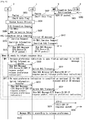
- Fig. 5 is an example timing diagram illustrating the provision of assistance information during connection setup by the MTC device 2 (denoted 'UE'). This procedure may be followed, for example, in case of a mobile originated (MO) small data transmission scenario.
- MO mobile originated
- the MTC device 2 initially performs a random access procedure with the base station 5 in order to be able to communicate with the base station 5.
- the MTC device 2 Once the MTC device 2 is granted communication resources during the random access procedure, its RRC module 49 generates and sends, in step S506, a message requesting the base station 5 to establish an RRC connection for/with the MTC device 2.
- This 'RRC connection request' includes information identifying the MTC device 2 (e.g. its S-Temporary Mobile Subscriber Identity (S-TMSI)) and an indication that the MTC device 2 is configured to send/receive small data transmissions.
- S-TMSI S-Temporary Mobile Subscriber Identity
- the base station 5 (using its RRC module 69) generates and sends an 'RRC Connection Setup' message, as shown in step S508. After receiving this message, the MTC device 2 is ready to communicate with other devices via this base station 5. Since the RRC connection has been requested by the MTC device 2 for this purpose, this scenario can also be referred to as a mobile originated communication scenario.
- the MME 9, the base station 5, and/or any other network entity may not have information on the amount of data to be sent/received by this MTC device 2.
- the MTC device 2 provides information to assist the MME 9 and/or the base station 5 to manage the RRC connection that has been established in the preceding step.
- This assistance information can also be used by the MME 9 and/or the base station 5 to manage the S1 connection (between the base station 5 and the core network 7) for communications by this MTC device 2.
- the assistance information may be provided in anyone (or more) of the following ways:
- the MTC device 2 can provide a release preference indication to indicate its preference for the MME 9 (or alternatively the base station 5) to release the RRC and/or S1 connection for the MTC device 2 immediately (or at any point in time).
- the MTC device 2 If the MTC device 2 expects to receive response data (e.g. an acknowledgment) from another communications device or an MTC server, then it can provide a release preference indication to indicate its preference for the MME 9 (or alternatively the base station 5) to keep the RRC/S1 connection alive and only release the connection(s) after the response data is received.
- response data e.g. an acknowledgment
- MME 9 or alternatively the base station 5
- the MTC device 2 If the MTC device 2 expects/requires the establishment of a user-plane connection (e.g. in order to send/receive data other than 'small data communications' data), then it can provide a release preference indication to indicate its preference for the MME 9 (or alternatively the base station 5) to trigger a full service request for user-plane establishment.
- a release preference indication to indicate its preference for the MME 9 (or alternatively the base station 5) to trigger a full service request for user-plane establishment.
- the MTC device 2 has two main options to indicate its release preference.
- the MTC device 2 (using its RRC module 49) generates and sends, at step S510, a message to the base station 5 indicating that the RRC connection has been set up (e.g. an 'RRC Connection Setup Complete' message).
- the RRC module 49 also includes in this RRC message a NAS message generated by the NAS module 47.
- This NAS message includes, amongst others, the MTC device's 2 release preference indication and the initial data packet ('UDP/IP packet') that the MTC device 2 needs to send to another communications device (or server).
- the base station 5 forwards the contents of the message received at S510 to the MME 9. This is done by its S1 module 67 generating and sending a so-called 'Initial UE message' over the S1 interface.
- This S1 message identifies (by its S-TMSI) the MTC device 2 for which the RRC connection has been set up and also includes the NAS message carrying the MTC device's 2 release preference indication and its initial data packet.
- the MTC device 2 may use any suitable NAS information element to provide its release preference indication to the MME 9 or the base station 5 via the MME 9 (e.g. a 'release preference indication' IE included in the NAS message).
- any suitable NAS information element to provide its release preference indication to the MME 9 or the base station 5 via the MME 9 (e.g. a 'release preference indication' IE included in the NAS message).
- the MTC device 2 (using its RRC module 49) generates and sends, at step S520, an RRC message to the base station 5 indicating that the RRC connection has been set up (e.g. an 'RRC Connection Setup Complete' message).
- the RRC module 49 includes in this RRC message a NAS message generated by the NAS module 47 (and this NAS message includes the MTC device's 2 initial data packet).
- the MTC device 2 includes its release preference indication in the RRC message (generated by its RRC module 49).
- the MTC device 2 may use any suitable RRC information element to provide its release preference indication (e.g. a 'release preference indication' IE included in the RRC message).
- the base station 5 forwards the contents of the message received at S520 to the MME 9. This is done by its S1 module 67 generating and sending a so-called 'Initial UE message' over the S1 interface.
- This S1 message identifies (by its S-TMSI) the MTC device 2 for which the RRC connection has been set up by the base station 5 and also includes the NAS message carrying the initial data packet by the MTC device 2. Since the MME 9 is not able to handle RRC information elements, the base station 5 includes the MTC device's 2 release preference indication in a suitable information element within the S1 message.
- the MME 9 upon receipt of the Initial UE message (at S512/S522) the MME 9 proceeds to setting up the connection for the MTC device 2 in the core network 7 so that the MTC device 2 can send/receive data packets to other communications devices and/or servers.
- step S534 the MME 9 generates and sends a user-plane GPRS Tunnelling Protocol (GTP-U) message to the gateway 8 serving the MTC device 2.
- GTP-U message also includes user-plane data, i.e. the initial data packet ('UDP/IP packet') sent by the MTC device 2, which is then forwarded by the gateway 8 to its intended recipient (at S536).
- the MME 9 or the base station 5 can start managing the RRC/S 1 connection for the MTC device 2 in accordance with the received release preference indication.
- the MME 9 or the base station 5 can initiate release of the RRC/S 1 connection immediately after the initial data packet has been successfully forwarded to the recipient (or at least to the serving gateway 8), i.e. any time after step S534.
- the MME 9 or the base station 5 can initiate the release of the RRC/S 1 connection only after response data (e.g. an acknowledgement packet) for the initial data packet has been received by the MTC device 2.
- response data e.g. an acknowledgement packet
- the MTC device 2 may send further data packets and hence the RRC/S 1 connection should be preferably maintained.
- the MTC device 2 is not expected to send any further data packets after receipt of the response data and hence the RRC/S 1 connection can be released accordingly.
- the MME 9 or the base station 5 does not initiate the release of the RRC/S 1 connection until at least receiving further indication from the MTC device 2 and/or fulfilment of other release conditions (e.g. expiry of a user inactivity timer at the base station 5, receiving a request from another network entity to release the RRC/S 1 connection, receiving an error indication, data held at the MME 9 indicates that the connection can be released, etc).
- Fig. 6 is another example timing diagram illustrating the provision of assistance information during an information transfer procedure between the MTC device 2 and the mobility management entity 9. This procedure may be followed, for example, in case of a mobile terminated (MT) small data transmission scenario.
- MT mobile terminated
- the serving gateway 8 receives data for the MC device 2 (e.g. from another communications device or a remote server). Therefore, in step S601, the gateway 8 generates and sends to the MME 9 a message notifying the MME 9 about the downlink data for the MTC device 2 ('Downlink Data Notification' message). The gateway 8 includes in this message the data (e.g. 'UDP/IP packet') to be delivered to the MTC device 2.
- the data e.g. 'UDP/IP packet'
- the MME 9 Upon receipt of the Downlink Data Notification message, the MME 9 initiates paging of the MTC device 2, as shown in step S602, which is performed by the base station 5 in step S603. If the data for the MTC device 2 is indicated to comprise data in accordance with the small data transmissions functionality, the paging message for the MTC device 2 also indicates this, e.g. by setting a flag (e.g. Small data flag) appropriately. At this point, the downlink data for the MTC device 2 is temporarily stored in the memory 79 of the MME 9 and awaits delivery to the MTC device 2 once an RRC connection has been set up.
- a flag e.g. Small data flag
- the MTC device 2 In response to the paging message, the MTC device 2 performs a random access procedure with the base station 5, as shown in step S604, so that it can communicate (i.e. receive the incoming data) via the base station 5.
- the MTC device 2 Once the MTC device 2 is granted communication resources, its RRC module 49 generates and sends, in step S606, a message requesting the base station 5 to establish an RRC connection for/with the MTC device 2.
- This 'RRC connection request' includes information identifying the MTC device 2 (e.g. its S-TMSI).
- the base station 5 (using its RRC module 69) generates and sends an 'RRC Connection Setup' message, as shown in step S608.
- the MTC device 2 After receiving this message, the MTC device 2 is ready to communicate with other devices via this base station 5. Since the RRC connection has been requested by the MTC device 2 in response to a paging message indicating downlink data, this scenario can also be referred to as a mobile terminated communication scenario.
- the MTC device 2 confirms that the RRC connection has been successfully set up by using its RRC module 49 to generate and send, at step S610, a message to the base station 5 indicating that the RRC connection has been set up (e.g. an 'RRC Connection Setup Complete' message).
- the MTC device 2 also includes in this RRC message an indication of the service being requested, i.e. the delivery of download data indicated by the preceding paging message.
- step S612 the base station 5 (using its S1 module 67) generates and sends a message to the MME 9 (e.g. an 'Initial UE message').
- This S1 message identifies (by its S-TMSI) the MTC device 2 for which the RRC connection has been set up and also includes the service request received from the MTC device 2.
- the MME 9 Upon receipt of the message sent at step S612, the MME 9 processes the service request and, using its NAS module 87, it generates a new NAS message to the MTC device 2 and includes in this message, amongst others, the downlink data that is stored in its memory 79. As shown in step S614, the MME 9 generates and sends a downlink message (e.g. a 'Downlink NAS Transport' message) to the base station 5 over the S1 interface. This message includes the new NAS message carrying the downlink data for the MTC device 2 and instructs the base station 5 to forward the NAS message to the MTC device 2 over the RRC interface.
- a downlink message e.g. a 'Downlink NAS Transport' message
- the base station 5 (using its RRC module 69) generates and sends an RRC message to transfer the downlink data (e.g. a 'Downlink Information Transfer' message) to the MTC device 2 - as shown in step S616.
- This RRC message includes the NAS message generated by the MME 9 (which includes the data for the MTC device 2).
- the MME 9, the base station 5, and/or any other network entity may not have information on the amount of data to be received (and/or sent) by this MTC device 2 other than the initial data packet received at step S600.
- the MTC device 2 provides information to assist the MME 9 and/or the base station 5 to manage the RRC connection that has been established in the preceding step.
- This assistance information can also be used by the MME 9 and/or the base station 5 to manage the S1 connection (between the base station 5 and the core network 7) for communications by this MTC device 2, as described above.
- the MTC device 2 may skip the following steps and hence conserve its battery power. In this case, the base station 5 and/or the MME 9 can still rely on conventional techniques to release the RRC/S 1 connection for this MTC device 2.
- the MTC device 2 does send assistance information, in case of an MT scenario it has two main options to indicate its release preference, as shown in Fig. 6 .
- the MTC device 2 (using its RRC module 49) generates and sends, at step S620, a message to the base station 5 for sending uplink data (e.g. an 'Uplink Information Transfer' message).
- the RRC module 49 also includes in this message a new NAS message generated by the NAS module 47.
- This NAS message includes, amongst others, the MTC device's 2 release preference indication and any response data ('UDP/IP response packet') that the MTC device 2 needs to send.
- the base station 5 forwards the contents of the message received at S620 to the MME 9. This is done by its S1 module 67 generating and sending a so-called 'Uplink NAS Transport' message over the S1 interface.
- This S1 message includes the new NAS message carrying the MTC device's 2 release preference indication and its response data packet.
- the MTC device 2 may use any suitable NAS information element to provide its release preference indication to the MME 9 or the base station 5 via the MME 9 (e.g. a 'release preference indication' IE included in the NAS message).
- any suitable NAS information element to provide its release preference indication to the MME 9 or the base station 5 via the MME 9 (e.g. a 'release preference indication' IE included in the NAS message).
- the MTC device 2 (using its RRC module 49) generates and sends, at step S630, a message to the base station 5 for sending uplink data (e.g. an 'Uplink Information Transfer' message).
- the RRC module 49 includes in this RRC message the new NAS message generated by the NAS module 47 (and this NAS message includes the MTC device's 2 response data packet).
- the MTC device 2 includes its release preference indication in the RRC message (generated by its RRC module 49).
- the MTC device 2 may use any suitable RRC information element to provide its release preference indication (e.g. a 'release preference indication' IE included in the RRC message).
- the base station 5 forwards the contents of the message received at S630 to the MME 9. This is done by its S1 module 67 generating and sending a so-called 'Uplink NAS Transport' message over the S1 interface.
- This S1 message thus includes the NAS message carrying the response data packet by the MTC device 2. Since the MME 9 is not able to handle RRC information elements, the base station 5 includes the MTC device's 2 release preference indication in a suitable information element within the S1 message.
- Steps S634 to S640 generally correspond to steps S534 to S540, respectively, hence their description is omitted for simplicity.
- the above exemplary embodiments may result in improved management of the (RRC/S1) connection release in case of small data transmissions by the MTC device. This is achieved by considering information provided by the MTC device 2 (or an MTC application of a mobile telephone 3), which is normally not available at the network nodes. By taking into account the assistance information from the MTC device 2, the S1 and RRC connections can be advantageously:
- the release preference is based on information (expected communication) that may not be available to the network entity controlling the RRC/S1 connection, the provision of such assistance information by the MTC device 2 can result in a more optimal usage of the overall resources of the communication system 1.
- an MME was given as an example NAS entity communicating with the MTC device (and/or the mobile telephone).
- the release preference indication may be provided to any other NAS-capable communications entity, e.g. a Serving GPRS Support Node (SGSN) within (or coupled to) the core network.
- SGSN Serving GPRS Support Node
- any MTC-capable mobile telephone i.e. a mobile telephone running an MTC client and/or supporting the small data transmission functionality
- the release preference indication may be provided using any suitable IE and/or any signalling message other than the NAS/RRC/S1 messages described above. It will also be appreciated that the release preference indication may be included in any part of the NAS/RRC/S1 message.
- the release preference indication given by the MTC device is described to relate to an existing communication (e.g. small data transmission) by the MTC device.
- this preference may relate to any future communications by the MTC device (i.e. until an updated preference indication is provided overriding any previous preference).
- a separate preference may be indicated for MO and MT communications within the same or in different signalling messages.
- any one or more of the above described options A to D may be used in combination.
- the MTC device's release preference may comprise a default setting (either as a default factory configuration or as an application/subscriber specific setting).
- the default setting may be provided, for example, by the MTC device and/or the HSS and/or any other network entity either as part of the above described procedures or independently. If a default setting is used, it will be appreciated that the MTC device may only indicate its release preference only if a release preference other than the default one is to be applied for a particular communication by the MTC device. Thus, in the absence of an explicit release preference, the base station / MME may apply the default release preference for communications by the MTC device.
- the base station is described to obtain the MTC device's preference indication from an information element included in the RRC part of the message sent from the MTC device to the MME.
- the base station may obtain the MTC device's preference indication from the MME (i.e. indirectly) if this indication is included in the NAS part of the message sent by the MTC device (which the base station may not be able to access). This may be beneficial for network operators wishing to maintain control of the RRC/S 1 release procedure at the base station rather than the MME irrespective of the type of information element used by the MTC device.
- steps S540 and S640 are shown to take place only after the initial data packet has been transmitted from the MME to the gateway. However, it will be appreciated that steps S540/S640 may also take place as soon as the release preference indication is received from the MTC device and/or may take place at different time for the base station and the MME, depending on when they obtain the MTC device's release preference indication (e.g. after step S510/S520 in case of the base station and after step S512/S522 in case of the MME).
- a 3GPP radio communications (radio access) technology is used.
- any other radio communications technology i.e. WLAN, Wi-Fi, WiMAX, Bluetooth, etc.
- WLAN wireless local area network
- Wi-Fi Wireless Fidelity
- WiMAX wireless personal area network
- Bluetooth wireless personal area network
- machine type communication applications are listed in the following table (source: 3GPP TS 22.368, Annex B). This list is not exhaustive and is intended to be indicative of the scope of machine type communication applications.
- Service Area MTC applications Security Surveillance systems Backup for landline Control of physical access (e.g. to buildings) Car/driver security Tracking & Tracing Fleet Management Order Management Pay as you drive Asset Tracking Navigation Traffic information Road tolling Road traffic optimisation/steering Payment Point of sales Vending machines Gaming machines Health Monitoring vital signs Supporting the aged or handicapped Web Access Telemedicine points Remote diagnostics Remote Maintenance/Control Sensors Lighting Pumps Valves Elevator control Vending machine control Vehicle diagnostics Metering Power Gas Water Heating Grid control Industrial metering Consumer Devices Digital photo frame Digital camera eBook
- the MTC device, the base station, and the mobility management entity are described for ease of understanding as having a number of discrete functional components or modules. Whilst these modules may be provided in this way for certain applications, for example where an existing system has been modified to implement the invention, in other applications, for example in systems designed with the inventive features in mind from the outset, these modules may be built into the overall operating system or code and so these modules may not be discernible as discrete entities.
- the software modules may be provided in compiled or un-compiled form and may be supplied to the MTC device, to the mobile telephone, to the base station or to the mobility management entity as a signal over a computer network, or on a recording medium. Further, the functionality performed by part or all of this software may be performed using one or more dedicated hardware circuits. However, the use of software modules is preferred as it facilitates the updating of the MTC device (or the mobile telephone having an MTC application), the base station, the mobility management entity in order to update their functionalities.
- Non-transitory computer readable media include any type of tangible storage media. Examples of non-transitory computer readable media include magnetic storage media (such as floppy disks, magnetic tapes, hard disk drives, etc.), optical magnetic storage media (e.g.
- the software modules may be provided to a computer using any type of transitory computer readable media.
- transitory computer readable media include electric signals, optical signals, and electromagnetic waves.
- Transitory computer readable media can provide the software modules to a computer via a wired communication line (e.g. electric wires, and optical fibers) or a wireless communication line.
Landscapes
- Engineering & Computer Science (AREA)
- Computer Networks & Wireless Communication (AREA)
- Signal Processing (AREA)
- Mobile Radio Communication Systems (AREA)
Claims (15)
- Kommunikationsvorrichtung (2) für ein Drahtloskommunikationssystem (1), wobei die Kommunikationsvorrichtung (2) aufweist:eine Einrichtung (45) zum Bestimmen, ob eine Downlink-Datenübertragung erwartet wird; undeine Einrichtung (47, 49) zum Übertragen einer NAS-, Non-Access Stratum, Signalisierung, die Uplink-Daten und Unterstützungsinformation enthält, die anzeigt, ob im Anschluss an eine Uplink-Übertragung eine Downlink-Datenübertragung erwartet wird, an eine Mobility Management Entity, MME (9), über eine Basisstation (5) zur Verwendung durch die MME (9) beim Bestimmen, ob eine Verbindung für die Kommunikationsvorrichtung (2) freigegeben werden soll.
- Kommunikationsvorrichtung (2) nach Anspruch 1, wobei die Verbindung eine RRC-, Funkressourcensteuerung, und/oder eine S1-Verbindung aufweist.
- Kommunikationsvorrichtung (2) nach Anspruch 1 oder 2, wobei die Übertragungseinrichtung (47) dafür konfiguriert ist, die Unterstützungsinformation während eines RRC-Verbindungsaufbaus zu übertragen.
- Basisstation (5) für ein Drahtloskommunikationssystem (1), wobei die Basisstation (5) aufweist:eine Einrichtung (69) zum Empfangen einer NAS-, Non-Access-Stratum, Signalisierung, die Uplink-Daten und Unterstützungsinformation enthält, die anzeigt, ob im Anschluss an eine Uplink-Übertragung eine Downlink-Datenübertragung durch eine Kommunikationsvorrichtung (2) erwartet wird, von der Kommunikationsvorrichtung (2) zur Verwendung durch eine Mobility Management Entity, MME (9), beim Bestimmen, ob eine Verbindung für die Kommunikationsvorrichtung (2) freigegeben werden soll; undeine Einrichtung (67) zum Übertragen der NAS-Signalisierung an die MME (9).
- Basisstation (5) nach Anspruch 4, mit einer Einrichtung (67) zum Empfangen, in dem Fall, dass die Unterstützungsinformation anzeigt, dass eine Downlink-Datenübertragung im Anschluss an die Uplink-Übertragung erwartet wird, einer Signalisierung von der MME (9) nach der Downlink-Übertragung, die eine Freigabe für die Verbindung für das Kommunikationsgerät (2) einleitet.
- Basisstation (5) nach Anspruch 4 oder 5, wobei die Empfangseinrichtung (69) dafür konfiguriert ist, die Unterstützungsinformation während des RRC-Verbindungsaufbaus zu empfangen.
- Basisstation (5) nach einem der Ansprüche 4 bis 6, wobei die Übertragungseinrichtung (67) dafür konfiguriert ist, die Unterstützungsinformation unter Verwendung einer anfänglichen UE-Nachricht an die MME (9) weiterzuleiten.
- Mobility Management Entity, MME (9), für ein Drahtloskommunikationssystem (1), wobei die MME (9) aufweist:
eine Einrichtung (87) zum Empfangen einer NAS-, Non-Access Stratum, Signalisierung, die Uplink-Daten und Unterstützungsinformation enthält, die anzeigt, ob im Anschluss an eine Uplink-Übertragung eine Downlink-Datenübertragung durch eine Kommunikationsvorrichtung (2) erwartet wird, von der Kommunikationsvorrichtung (2) über eine Basisstation (5) zur Verwendung beim Bestimmen, ob eine Verbindung für die Kommunikationsvorrichtung (2) freigegeben werden soll. - MME (9) nach Anspruch 8, mit einer Einrichtung (89) zum Übertragen, in dem Fall, dass die Unterstützungsinformation anzeigt, dass eine Downlink-Datenübertragung im Anschluss an die Uplink-Übertragung erwartet wird, einer Signalisierung an die Basisstation (5) nach der Downlink-Übertragung, um eine Freigabe für die Verbindung für die Kommunikationsvorrichtung (2) einzuleiten.
- MME (9) nach Anspruch 8 oder 9, wobei die Verbindung eine RRC-, Funkressourcensteuerung, und/oder eine S1-Verbindung aufweist.
- Drahtloskommunikationssystem mit der Kommunikationsvorrichtung (2) nach einem der Ansprüche 1 bis 3, der Basisstation (5) nach einem der Ansprüche 4 bis 7 und der MME (9) nach einem der Ansprüche 8 bis 10.
- Verfahren, das durch eine Kommunikationsvorrichtung (2) in einem Drahtloskommunikationssystem (1) ausgeführt wird, wobei das Verfahren die Schritte aufweist:Bestimmen, ob eine Downlink-Datenübertragung erwartet wird; undÜbertragen (S510) einer NAS-, Non-Access Stratum, Signalisierung, die Uplink-Daten und Unterstützungsinformation enthält, die anzeigt, ob im Anschluss an eine Uplink-Übertragung eine Downlink-Datenübertragung erwartet wird, an eine Mobility Management Entity, MME (9), über eine Basisstation (5) zur Verwendung durch die MME (9) beim Bestimmen, ob eine Verbindung für die Kommunikationsvorrichtung (2) freigegeben werden soll.
- Verfahren, das durch eine Basisstation (5) in einem Drahtloskommunikationssystem (1) ausgeführt wird, wobei das Verfahren die Schritte aufweist:Empfangen (S510) einer NAS-, Non-Access Stratum, Signalisierung, die Uplink-Daten und Unterstützungsinformation enthält, die anzeigt, ob im Anschluss an eine Uplink-Übertragung eine Downlink-Datenübertragung durch eine Kommunikationsvorrichtung (2) erwartet wird, von der Kommunikationsvorrichtung (2) zur Verwendung durch eine Mobility Management Entity, MME (9), beim Bestimmen, ob eine Verbindung für die Kommunikationsvorrichtung (2) freigegeben werden soll; undÜbertragen (S512) der NAS-Signalisierung an die MME (9).
- Verfahren, das durch eine Mobility Management Entity, MME (9), in einem Drahtloskommunikationssystem (1) ausgeführt wird, wobei das Verfahren den Schritt aufweist:
Empfangen (S512) einer NAS-, Non-Access Stratum, Signalisierung, die Uplink-Daten und Unterstützungsinformation enthält, die anzeigt, ob im Anschluss an eine Uplink-Übertragung eine Downlink-Datenübertragung durch eine Kommunikationsvorrichtung (2) erwartet wird, von der Kommunikationsvorrichtung (2) über eine Basisstation (5) zur Verwendung beim Bestimmen, ob eine Verbindung für die Kommunikationsvorrichtung (2) freigegeben werden soll. - Produkt mit computerimplementierbaren Anweisungen, das computerimplementierbare Anweisungen enthält, die eine programmierbare Kommunikationsvorrichtung veranlassen, das Verfahren nach einem der Ansprüche 12 bis 14 auszuführen.
Priority Applications (1)
| Application Number | Priority Date | Filing Date | Title |
|---|---|---|---|
| EP20215780.6A EP3826334B1 (de) | 2013-05-20 | 2014-05-16 | Vorrichtungen und verfahren |
Applications Claiming Priority (2)
| Application Number | Priority Date | Filing Date | Title |
|---|---|---|---|
| GB1309074.1A GB2514357A (en) | 2013-05-20 | 2013-05-20 | Communications system |
| PCT/JP2014/002604 WO2014188694A1 (en) | 2013-05-20 | 2014-05-16 | Communications device, apparatus, system, method and computer implementable instructions product |
Related Child Applications (2)
| Application Number | Title | Priority Date | Filing Date |
|---|---|---|---|
| EP20215780.6A Division EP3826334B1 (de) | 2013-05-20 | 2014-05-16 | Vorrichtungen und verfahren |
| EP20215780.6A Division-Into EP3826334B1 (de) | 2013-05-20 | 2014-05-16 | Vorrichtungen und verfahren |
Publications (3)
| Publication Number | Publication Date |
|---|---|
| EP3000280A1 EP3000280A1 (de) | 2016-03-30 |
| EP3000280A4 EP3000280A4 (de) | 2017-01-25 |
| EP3000280B1 true EP3000280B1 (de) | 2021-02-17 |
Family
ID=48747049
Family Applications (2)
| Application Number | Title | Priority Date | Filing Date |
|---|---|---|---|
| EP14800957.4A Active EP3000280B1 (de) | 2013-05-20 | 2014-05-16 | Kommunikationsvorrichtung, vorrichtung, system, verfahren und computerimplementierbares anweisungsprodukt |
| EP20215780.6A Active EP3826334B1 (de) | 2013-05-20 | 2014-05-16 | Vorrichtungen und verfahren |
Family Applications After (1)
| Application Number | Title | Priority Date | Filing Date |
|---|---|---|---|
| EP20215780.6A Active EP3826334B1 (de) | 2013-05-20 | 2014-05-16 | Vorrichtungen und verfahren |
Country Status (6)
| Country | Link |
|---|---|
| US (4) | US10009941B2 (de) |
| EP (2) | EP3000280B1 (de) |
| JP (3) | JP6015868B2 (de) |
| ES (1) | ES2855127T3 (de) |
| GB (1) | GB2514357A (de) |
| WO (1) | WO2014188694A1 (de) |
Families Citing this family (28)
| Publication number | Priority date | Publication date | Assignee | Title |
|---|---|---|---|---|
| JPH0729802B2 (ja) | 1988-12-01 | 1995-04-05 | 佐々木硝子株式会社 | 模様を有する結晶化ガラス物品の製造方法 |
| JPH0661767B2 (ja) | 1991-11-05 | 1994-08-17 | 株式会社ヒラノテクシード | 熱風乾燥装置 |
| GB2514357A (en) * | 2013-05-20 | 2014-11-26 | Nec Corp | Communications system |
| KR20160021262A (ko) * | 2013-07-29 | 2016-02-24 | 후지쯔 가부시끼가이샤 | 전송 방식 전환 방법, ue 및 기지국 |
| EP3114895B1 (de) * | 2014-03-07 | 2019-09-11 | Telefonaktiebolaget LM Ericsson (publ) | Handhabung von nachrichten |
| EP3386265B1 (de) * | 2015-12-04 | 2021-07-21 | LG Electronics Inc. | Verfahren und vorrichtung zur datenübertragung einer benutzergeräte-id in einem drahtloskommunikationssystem |
| MY197196A (en) * | 2016-01-12 | 2023-05-31 | Huawei Tech Co Ltd | Bearer setup method, apparatus,and system |
| US10149160B2 (en) | 2016-05-11 | 2018-12-04 | Bank Of America Corporation | Recognizing and authenticating mobile devices based on unique cross-channel bindings |
| EP3501234A4 (de) * | 2016-08-22 | 2020-04-01 | Nokia Technologies Oy | Sicherheitsverfahren |
| KR102327639B1 (ko) * | 2017-03-10 | 2021-11-17 | 삼성전자 주식회사 | Mobile Initiated Communication Only mode 단말의 연결을 유지시키는 방법 |
| CN109863783B (zh) | 2017-04-28 | 2022-05-31 | Lg 电子株式会社 | 根据edt发送数据的方法 |
| US11039497B2 (en) * | 2017-09-18 | 2021-06-15 | Qualcomm Incorporated | User plane based small data service |
| EP3689044B1 (de) * | 2017-09-29 | 2022-05-18 | Telefonaktiebolaget LM Ericsson (Publ) | Systeme und verfahren, die eine frühe standby-datenübertragungslösung bieten, die einen energiesparmodus ermöglicht |
| CN110072270A (zh) * | 2017-10-26 | 2019-07-30 | 中国电信股份有限公司 | 无线资源控制连接释放方法、装置和系统 |
| CN116033603B (zh) * | 2017-11-16 | 2025-11-07 | 中兴通讯股份有限公司 | 连接控制、业务处理方法及装置 |
| KR102381375B1 (ko) * | 2018-03-30 | 2022-04-01 | 삼성전자주식회사 | 이동통신 시스템에서 Cellular IoT 서비스를 제공하는 방법 및 장치 |
| WO2019190297A1 (en) * | 2018-03-30 | 2019-10-03 | Samsung Electronics Co., Ltd. | Method and apparatus for providing cellular iot service in mobile communication system |
| US11418998B2 (en) * | 2018-04-17 | 2022-08-16 | Telefonaktiebolaget Lm Ericsson (Publ) | Wireless device, network node, core node and methods for handling radio communication of data |
| GB2588403B (en) * | 2019-10-22 | 2021-10-20 | Metaswitch Networks Ltd | Processing computer files |
| JP7729331B2 (ja) * | 2020-03-31 | 2025-08-26 | 日本電気株式会社 | 管理システム、コアネットワーク、移動体通信システム、方法、及びプログラム |
| CN115398976B (zh) * | 2020-04-08 | 2025-02-14 | 苹果公司 | 使用ue辅助信息的nr中的ue功率节省 |
| US20210337481A1 (en) * | 2020-04-23 | 2021-10-28 | Qualcomm Incorporated | Application information aided fast dormancy |
| EP4229996A1 (de) | 2020-10-19 | 2023-08-23 | Ofinno, LLC | Uplink-daten eines kleinen datenübertragungsverfahrens |
| WO2022236504A1 (zh) * | 2021-05-08 | 2022-11-17 | Oppo广东移动通信有限公司 | 通信方法及装置 |
| US11675733B2 (en) | 2021-06-15 | 2023-06-13 | Itron, Inc. | Techniques for release assistance indication assertion |
| US11830354B2 (en) * | 2021-06-15 | 2023-11-28 | Itron, Inc. | Techniques for release assistance indication assertion |
| US11818658B2 (en) | 2021-06-15 | 2023-11-14 | Itron, Inc. | Techniques for release assistance indication assertion |
| CN118715838A (zh) * | 2022-07-12 | 2024-09-27 | 中兴通讯股份有限公司 | 用于无线通信的方法、设备和计算机程序产品 |
Family Cites Families (18)
| Publication number | Priority date | Publication date | Assignee | Title |
|---|---|---|---|---|
| FI108203B (fi) * | 1998-11-27 | 2001-11-30 | Nokia Mobile Phones Ltd | Menetelmä ja järjestely tiedon siirtämiseksi pakettiradiopalvelussa |
| US8515436B2 (en) * | 2008-03-27 | 2013-08-20 | Qualcomm Incorporated | Management of wireless connections |
| AU2010321205B2 (en) * | 2009-11-23 | 2014-09-04 | Blackberry Limited | State or mode transition triggering based on SRI message transmission |
| KR101766474B1 (ko) | 2010-03-23 | 2017-08-23 | 인터디지탈 패튼 홀딩스, 인크 | 기계형 통신을 위한 효율적 시그널링을 위한 장치 및 그에 관한 방법 |
| US20120023234A1 (en) * | 2010-07-21 | 2012-01-26 | Nokia Corporation | Method and Apparatus for Establishing a Connection |
| EP3541143B1 (de) * | 2011-03-29 | 2023-11-29 | LG Electronics Inc. | Verfahren für ein benutzergerät zum senden und empfangen von daten in einem drahtloskommunikationssystem und vorrichtung dafür |
| EP2509345A1 (de) * | 2011-04-05 | 2012-10-10 | Panasonic Corporation | Verbesserte Übertragung kleiner Datenmengen für MTC-Vorrichtungen |
| GB2493216B (en) | 2011-07-29 | 2016-02-03 | Sca Ipla Holdings Inc | Mobile communications network, infrastructure equipment, mobile communications terminal and method |
| GB2493349A (en) * | 2011-07-29 | 2013-02-06 | Intellectual Ventures Holding 81 Llc | Mobile communications network with simplified handover |
| US9973877B2 (en) * | 2011-09-23 | 2018-05-15 | Htc Corporation | Method of handling small data transmission |
| WO2013144606A1 (en) * | 2012-03-27 | 2013-10-03 | Research In Motion Limited | User equipment preference indicator for suspension of radio communications |
| CN103391532B (zh) * | 2012-05-11 | 2018-08-28 | 中兴通讯股份有限公司 | 小量数据上下行传输方法、及相应终端和移动性管理单元 |
| US9100160B2 (en) * | 2012-08-03 | 2015-08-04 | Intel Corporation | Apparatus and method for small data transmission in 3GPP-LTE systems |
| EP2701406A1 (de) * | 2012-08-23 | 2014-02-26 | ST-Ericsson SA | Kommunikationsstatus-Einstellung basierend auf der erwarteten Downlink-Datenmenge |
| CN104010382B (zh) * | 2013-02-25 | 2019-02-01 | 中兴通讯股份有限公司 | 数据传输方法、装置及系统 |
| US9049588B2 (en) * | 2013-02-28 | 2015-06-02 | Blackberry Limited | Communicating data in a predefined transmission mode |
| US9191178B2 (en) * | 2013-04-04 | 2015-11-17 | Intel IP Corporation | Enhanced node B and method for RRC connection establishment for small data transfers |
| GB2514357A (en) * | 2013-05-20 | 2014-11-26 | Nec Corp | Communications system |
-
2013
- 2013-05-20 GB GB1309074.1A patent/GB2514357A/en not_active Withdrawn
-
2014
- 2014-05-16 US US14/892,131 patent/US10009941B2/en active Active
- 2014-05-16 JP JP2015556891A patent/JP6015868B2/ja active Active
- 2014-05-16 ES ES14800957T patent/ES2855127T3/es active Active
- 2014-05-16 EP EP14800957.4A patent/EP3000280B1/de active Active
- 2014-05-16 WO PCT/JP2014/002604 patent/WO2014188694A1/en not_active Ceased
- 2014-05-16 EP EP20215780.6A patent/EP3826334B1/de active Active
-
2016
- 2016-09-29 JP JP2016190954A patent/JP6365614B2/ja active Active
-
2018
- 2018-06-07 US US16/002,810 patent/US10542578B2/en active Active
- 2018-07-04 JP JP2018127388A patent/JP6516055B2/ja active Active
-
2019
- 2019-12-10 US US16/709,355 patent/US11140739B2/en active Active
-
2021
- 2021-08-25 US US17/412,094 patent/US11706836B2/en active Active
Non-Patent Citations (1)
| Title |
|---|
| None * |
Also Published As
| Publication number | Publication date |
|---|---|
| JP2018186538A (ja) | 2018-11-22 |
| US10009941B2 (en) | 2018-06-26 |
| EP3826334B1 (de) | 2023-11-29 |
| ES2855127T3 (es) | 2021-09-23 |
| US11706836B2 (en) | 2023-07-18 |
| JP6015868B2 (ja) | 2016-10-26 |
| GB2514357A (en) | 2014-11-26 |
| US11140739B2 (en) | 2021-10-05 |
| EP3000280A1 (de) | 2016-03-30 |
| GB201309074D0 (en) | 2013-07-03 |
| US20200154503A1 (en) | 2020-05-14 |
| EP3826334A1 (de) | 2021-05-26 |
| JP6516055B2 (ja) | 2019-05-22 |
| JP2016522587A (ja) | 2016-07-28 |
| US10542578B2 (en) | 2020-01-21 |
| JP2017022771A (ja) | 2017-01-26 |
| US20180359803A1 (en) | 2018-12-13 |
| JP6365614B2 (ja) | 2018-08-01 |
| EP3000280A4 (de) | 2017-01-25 |
| US20160113057A1 (en) | 2016-04-21 |
| US20210385899A1 (en) | 2021-12-09 |
| WO2014188694A1 (en) | 2014-11-27 |
Similar Documents
| Publication | Publication Date | Title |
|---|---|---|
| US11706836B2 (en) | Communications device, apparatus, system, method and computer implementable instructions product | |
| US11405974B2 (en) | Communication system | |
| US10624004B2 (en) | Serving node relocating method in wireless communication system and device for same | |
| EP3437380B1 (de) | Laststeuerung aus optimierung von ciot-eps der steuerungsebene | |
| US10701753B2 (en) | Method and device for controlling set-up of user-plane bearer | |
| US20200037203A1 (en) | User equipment, system and communication method for managing overload in the context of control plane cellular internet of things evolved packet system optimisation | |
| CN107113537A (zh) | 针对省电模式和寻呼的服务能力服务器/epc协同 | |
| JP2018529281A (ja) | 最適化されたショートメッセージトランスポート | |
| US20170164288A1 (en) | Method and apparatus for communication management | |
| WO2012174943A1 (zh) | 一种确定终端状态的方法、装置和系统 | |
| EP4218289A1 (de) | Netzwerk-slice-quoten in gegenwart von interworking | |
| US20220217616A1 (en) | Applying Access Control in a Communication Device | |
| CN105940737B (zh) | 服务控制系统、用户装置以及服务控制方法 | |
| CN104105051A (zh) | 触发消息处理方法、装置及通信系统 |
Legal Events
| Date | Code | Title | Description |
|---|---|---|---|
| PUAI | Public reference made under article 153(3) epc to a published international application that has entered the european phase |
Free format text: ORIGINAL CODE: 0009012 |
|
| 17P | Request for examination filed |
Effective date: 20151216 |
|
| AK | Designated contracting states |
Kind code of ref document: A1 Designated state(s): AL AT BE BG CH CY CZ DE DK EE ES FI FR GB GR HR HU IE IS IT LI LT LU LV MC MK MT NL NO PL PT RO RS SE SI SK SM TR |
|
| AX | Request for extension of the european patent |
Extension state: BA ME |
|
| DAX | Request for extension of the european patent (deleted) | ||
| A4 | Supplementary search report drawn up and despatched |
Effective date: 20170102 |
|
| RIC1 | Information provided on ipc code assigned before grant |
Ipc: H04W 4/20 20090101ALI20161221BHEP Ipc: H04W 76/06 20090101AFI20161221BHEP |
|
| REG | Reference to a national code |
Ref country code: DE Ref legal event code: R079 Ref document number: 602014074891 Country of ref document: DE Free format text: PREVIOUS MAIN CLASS: H04W0076060000 Ipc: H04W0004700000 |
|
| GRAP | Despatch of communication of intention to grant a patent |
Free format text: ORIGINAL CODE: EPIDOSNIGR1 |
|
| STAA | Information on the status of an ep patent application or granted ep patent |
Free format text: STATUS: GRANT OF PATENT IS INTENDED |
|
| RIC1 | Information provided on ipc code assigned before grant |
Ipc: H04W 4/70 20180101AFI20200723BHEP |
|
| INTG | Intention to grant announced |
Effective date: 20200821 |
|
| GRAS | Grant fee paid |
Free format text: ORIGINAL CODE: EPIDOSNIGR3 |
|
| GRAA | (expected) grant |
Free format text: ORIGINAL CODE: 0009210 |
|
| STAA | Information on the status of an ep patent application or granted ep patent |
Free format text: STATUS: THE PATENT HAS BEEN GRANTED |
|
| AK | Designated contracting states |
Kind code of ref document: B1 Designated state(s): AL AT BE BG CH CY CZ DE DK EE ES FI FR GB GR HR HU IE IS IT LI LT LU LV MC MK MT NL NO PL PT RO RS SE SI SK SM TR |
|
| REG | Reference to a national code |
Ref country code: GB Ref legal event code: FG4D |
|
| REG | Reference to a national code |
Ref country code: CH Ref legal event code: EP |
|
| REG | Reference to a national code |
Ref country code: DE Ref legal event code: R096 Ref document number: 602014074891 Country of ref document: DE |
|
| REG | Reference to a national code |
Ref country code: AT Ref legal event code: REF Ref document number: 1363125 Country of ref document: AT Kind code of ref document: T Effective date: 20210315 |
|
| REG | Reference to a national code |
Ref country code: IE Ref legal event code: FG4D |
|
| REG | Reference to a national code |
Ref country code: LT Ref legal event code: MG9D |
|
| REG | Reference to a national code |
Ref country code: NL Ref legal event code: MP Effective date: 20210217 |
|
| PG25 | Lapsed in a contracting state [announced via postgrant information from national office to epo] |
Ref country code: LT Free format text: LAPSE BECAUSE OF FAILURE TO SUBMIT A TRANSLATION OF THE DESCRIPTION OR TO PAY THE FEE WITHIN THE PRESCRIBED TIME-LIMIT Effective date: 20210217 Ref country code: PT Free format text: LAPSE BECAUSE OF FAILURE TO SUBMIT A TRANSLATION OF THE DESCRIPTION OR TO PAY THE FEE WITHIN THE PRESCRIBED TIME-LIMIT Effective date: 20210617 Ref country code: HR Free format text: LAPSE BECAUSE OF FAILURE TO SUBMIT A TRANSLATION OF THE DESCRIPTION OR TO PAY THE FEE WITHIN THE PRESCRIBED TIME-LIMIT Effective date: 20210217 Ref country code: FI Free format text: LAPSE BECAUSE OF FAILURE TO SUBMIT A TRANSLATION OF THE DESCRIPTION OR TO PAY THE FEE WITHIN THE PRESCRIBED TIME-LIMIT Effective date: 20210217 Ref country code: GR Free format text: LAPSE BECAUSE OF FAILURE TO SUBMIT A TRANSLATION OF THE DESCRIPTION OR TO PAY THE FEE WITHIN THE PRESCRIBED TIME-LIMIT Effective date: 20210518 Ref country code: BG Free format text: LAPSE BECAUSE OF FAILURE TO SUBMIT A TRANSLATION OF THE DESCRIPTION OR TO PAY THE FEE WITHIN THE PRESCRIBED TIME-LIMIT Effective date: 20210517 Ref country code: NO Free format text: LAPSE BECAUSE OF FAILURE TO SUBMIT A TRANSLATION OF THE DESCRIPTION OR TO PAY THE FEE WITHIN THE PRESCRIBED TIME-LIMIT Effective date: 20210517 |
|
| REG | Reference to a national code |
Ref country code: AT Ref legal event code: MK05 Ref document number: 1363125 Country of ref document: AT Kind code of ref document: T Effective date: 20210217 |
|
| PG25 | Lapsed in a contracting state [announced via postgrant information from national office to epo] |
Ref country code: RS Free format text: LAPSE BECAUSE OF FAILURE TO SUBMIT A TRANSLATION OF THE DESCRIPTION OR TO PAY THE FEE WITHIN THE PRESCRIBED TIME-LIMIT Effective date: 20210217 Ref country code: LV Free format text: LAPSE BECAUSE OF FAILURE TO SUBMIT A TRANSLATION OF THE DESCRIPTION OR TO PAY THE FEE WITHIN THE PRESCRIBED TIME-LIMIT Effective date: 20210217 Ref country code: PL Free format text: LAPSE BECAUSE OF FAILURE TO SUBMIT A TRANSLATION OF THE DESCRIPTION OR TO PAY THE FEE WITHIN THE PRESCRIBED TIME-LIMIT Effective date: 20210217 Ref country code: NL Free format text: LAPSE BECAUSE OF FAILURE TO SUBMIT A TRANSLATION OF THE DESCRIPTION OR TO PAY THE FEE WITHIN THE PRESCRIBED TIME-LIMIT Effective date: 20210217 Ref country code: SE Free format text: LAPSE BECAUSE OF FAILURE TO SUBMIT A TRANSLATION OF THE DESCRIPTION OR TO PAY THE FEE WITHIN THE PRESCRIBED TIME-LIMIT Effective date: 20210217 |
|
| REG | Reference to a national code |
Ref country code: ES Ref legal event code: FG2A Ref document number: 2855127 Country of ref document: ES Kind code of ref document: T3 Effective date: 20210923 |
|
| PG25 | Lapsed in a contracting state [announced via postgrant information from national office to epo] |
Ref country code: IS Free format text: LAPSE BECAUSE OF FAILURE TO SUBMIT A TRANSLATION OF THE DESCRIPTION OR TO PAY THE FEE WITHIN THE PRESCRIBED TIME-LIMIT Effective date: 20210617 |
|
| PG25 | Lapsed in a contracting state [announced via postgrant information from national office to epo] |
Ref country code: CZ Free format text: LAPSE BECAUSE OF FAILURE TO SUBMIT A TRANSLATION OF THE DESCRIPTION OR TO PAY THE FEE WITHIN THE PRESCRIBED TIME-LIMIT Effective date: 20210217 Ref country code: EE Free format text: LAPSE BECAUSE OF FAILURE TO SUBMIT A TRANSLATION OF THE DESCRIPTION OR TO PAY THE FEE WITHIN THE PRESCRIBED TIME-LIMIT Effective date: 20210217 Ref country code: AT Free format text: LAPSE BECAUSE OF FAILURE TO SUBMIT A TRANSLATION OF THE DESCRIPTION OR TO PAY THE FEE WITHIN THE PRESCRIBED TIME-LIMIT Effective date: 20210217 Ref country code: SM Free format text: LAPSE BECAUSE OF FAILURE TO SUBMIT A TRANSLATION OF THE DESCRIPTION OR TO PAY THE FEE WITHIN THE PRESCRIBED TIME-LIMIT Effective date: 20210217 |
|
| REG | Reference to a national code |
Ref country code: DE Ref legal event code: R097 Ref document number: 602014074891 Country of ref document: DE |
|
| PG25 | Lapsed in a contracting state [announced via postgrant information from national office to epo] |
Ref country code: SK Free format text: LAPSE BECAUSE OF FAILURE TO SUBMIT A TRANSLATION OF THE DESCRIPTION OR TO PAY THE FEE WITHIN THE PRESCRIBED TIME-LIMIT Effective date: 20210217 Ref country code: RO Free format text: LAPSE BECAUSE OF FAILURE TO SUBMIT A TRANSLATION OF THE DESCRIPTION OR TO PAY THE FEE WITHIN THE PRESCRIBED TIME-LIMIT Effective date: 20210217 Ref country code: DK Free format text: LAPSE BECAUSE OF FAILURE TO SUBMIT A TRANSLATION OF THE DESCRIPTION OR TO PAY THE FEE WITHIN THE PRESCRIBED TIME-LIMIT Effective date: 20210217 |
|
| PLBE | No opposition filed within time limit |
Free format text: ORIGINAL CODE: 0009261 |
|
| STAA | Information on the status of an ep patent application or granted ep patent |
Free format text: STATUS: NO OPPOSITION FILED WITHIN TIME LIMIT |
|
| REG | Reference to a national code |
Ref country code: CH Ref legal event code: PL |
|
| 26N | No opposition filed |
Effective date: 20211118 |
|
| PG25 | Lapsed in a contracting state [announced via postgrant information from national office to epo] |
Ref country code: LI Free format text: LAPSE BECAUSE OF NON-PAYMENT OF DUE FEES Effective date: 20210531 Ref country code: LU Free format text: LAPSE BECAUSE OF NON-PAYMENT OF DUE FEES Effective date: 20210516 Ref country code: MC Free format text: LAPSE BECAUSE OF FAILURE TO SUBMIT A TRANSLATION OF THE DESCRIPTION OR TO PAY THE FEE WITHIN THE PRESCRIBED TIME-LIMIT Effective date: 20210217 Ref country code: CH Free format text: LAPSE BECAUSE OF NON-PAYMENT OF DUE FEES Effective date: 20210531 Ref country code: AL Free format text: LAPSE BECAUSE OF FAILURE TO SUBMIT A TRANSLATION OF THE DESCRIPTION OR TO PAY THE FEE WITHIN THE PRESCRIBED TIME-LIMIT Effective date: 20210217 |
|
| REG | Reference to a national code |
Ref country code: BE Ref legal event code: MM Effective date: 20210531 |
|
| PG25 | Lapsed in a contracting state [announced via postgrant information from national office to epo] |
Ref country code: SI Free format text: LAPSE BECAUSE OF FAILURE TO SUBMIT A TRANSLATION OF THE DESCRIPTION OR TO PAY THE FEE WITHIN THE PRESCRIBED TIME-LIMIT Effective date: 20210217 |
|
| PG25 | Lapsed in a contracting state [announced via postgrant information from national office to epo] |
Ref country code: IE Free format text: LAPSE BECAUSE OF NON-PAYMENT OF DUE FEES Effective date: 20210516 |
|
| PG25 | Lapsed in a contracting state [announced via postgrant information from national office to epo] |
Ref country code: IS Free format text: LAPSE BECAUSE OF FAILURE TO SUBMIT A TRANSLATION OF THE DESCRIPTION OR TO PAY THE FEE WITHIN THE PRESCRIBED TIME-LIMIT Effective date: 20210617 |
|
| PG25 | Lapsed in a contracting state [announced via postgrant information from national office to epo] |
Ref country code: BE Free format text: LAPSE BECAUSE OF NON-PAYMENT OF DUE FEES Effective date: 20210531 |
|
| PG25 | Lapsed in a contracting state [announced via postgrant information from national office to epo] |
Ref country code: HU Free format text: LAPSE BECAUSE OF FAILURE TO SUBMIT A TRANSLATION OF THE DESCRIPTION OR TO PAY THE FEE WITHIN THE PRESCRIBED TIME-LIMIT; INVALID AB INITIO Effective date: 20140516 |
|
| PG25 | Lapsed in a contracting state [announced via postgrant information from national office to epo] |
Ref country code: CY Free format text: LAPSE BECAUSE OF FAILURE TO SUBMIT A TRANSLATION OF THE DESCRIPTION OR TO PAY THE FEE WITHIN THE PRESCRIBED TIME-LIMIT Effective date: 20210217 |
|
| PG25 | Lapsed in a contracting state [announced via postgrant information from national office to epo] |
Ref country code: MK Free format text: LAPSE BECAUSE OF FAILURE TO SUBMIT A TRANSLATION OF THE DESCRIPTION OR TO PAY THE FEE WITHIN THE PRESCRIBED TIME-LIMIT Effective date: 20210217 |
|
| PG25 | Lapsed in a contracting state [announced via postgrant information from national office to epo] |
Ref country code: MT Free format text: LAPSE BECAUSE OF FAILURE TO SUBMIT A TRANSLATION OF THE DESCRIPTION OR TO PAY THE FEE WITHIN THE PRESCRIBED TIME-LIMIT Effective date: 20210217 |
|
| PGFP | Annual fee paid to national office [announced via postgrant information from national office to epo] |
Ref country code: DE Payment date: 20250521 Year of fee payment: 12 |
|
| PGFP | Annual fee paid to national office [announced via postgrant information from national office to epo] |
Ref country code: GB Payment date: 20250527 Year of fee payment: 12 Ref country code: ES Payment date: 20250627 Year of fee payment: 12 |
|
| PGFP | Annual fee paid to national office [announced via postgrant information from national office to epo] |
Ref country code: IT Payment date: 20250527 Year of fee payment: 12 |
|
| PGFP | Annual fee paid to national office [announced via postgrant information from national office to epo] |
Ref country code: FR Payment date: 20250528 Year of fee payment: 12 |
|
| PGFP | Annual fee paid to national office [announced via postgrant information from national office to epo] |
Ref country code: TR Payment date: 20250512 Year of fee payment: 12 |