EP3000206B1 - Verkettung von dienstzonen durch routenneuorganisation - Google Patents
Verkettung von dienstzonen durch routenneuorganisation Download PDFInfo
- Publication number
- EP3000206B1 EP3000206B1 EP14728777.5A EP14728777A EP3000206B1 EP 3000206 B1 EP3000206 B1 EP 3000206B1 EP 14728777 A EP14728777 A EP 14728777A EP 3000206 B1 EP3000206 B1 EP 3000206B1
- Authority
- EP
- European Patent Office
- Prior art keywords
- service
- zone
- service zone
- traffic
- route
- Prior art date
- Legal status (The legal status is an assumption and is not a legal conclusion. Google has not performed a legal analysis and makes no representation as to the accuracy of the status listed.)
- Not-in-force
Links
- 230000006870 function Effects 0.000 claims description 66
- 230000008676 import Effects 0.000 claims description 31
- 238000000034 method Methods 0.000 claims description 30
- 238000011144 upstream manufacturing Methods 0.000 claims description 7
- 238000000927 vapour-phase epitaxy Methods 0.000 description 33
- 230000007246 mechanism Effects 0.000 description 11
- 230000011664 signaling Effects 0.000 description 11
- 238000013507 mapping Methods 0.000 description 8
- 238000010586 diagram Methods 0.000 description 7
- 238000007726 management method Methods 0.000 description 7
- 238000012545 processing Methods 0.000 description 6
- 238000009434 installation Methods 0.000 description 5
- 230000005641 tunneling Effects 0.000 description 5
- 235000008694 Humulus lupulus Nutrition 0.000 description 4
- 230000008901 benefit Effects 0.000 description 3
- 238000005538 encapsulation Methods 0.000 description 3
- 230000003287 optical effect Effects 0.000 description 2
- 230000008569 process Effects 0.000 description 2
- 230000001413 cellular effect Effects 0.000 description 1
- 238000004891 communication Methods 0.000 description 1
- 238000012217 deletion Methods 0.000 description 1
- 230000037430 deletion Effects 0.000 description 1
- 238000005516 engineering process Methods 0.000 description 1
- 238000003780 insertion Methods 0.000 description 1
- 230000037431 insertion Effects 0.000 description 1
- 238000007689 inspection Methods 0.000 description 1
- 230000005055 memory storage Effects 0.000 description 1
- 230000006855 networking Effects 0.000 description 1
- 238000012805 post-processing Methods 0.000 description 1
- 238000004513 sizing Methods 0.000 description 1
- 230000001360 synchronised effect Effects 0.000 description 1
- 238000012546 transfer Methods 0.000 description 1
- 238000013519 translation Methods 0.000 description 1
Images




Classifications
-
- H—ELECTRICITY
- H04—ELECTRIC COMMUNICATION TECHNIQUE
- H04L—TRANSMISSION OF DIGITAL INFORMATION, e.g. TELEGRAPHIC COMMUNICATION
- H04L45/00—Routing or path finding of packets in data switching networks
- H04L45/02—Topology update or discovery
- H04L45/04—Interdomain routing, e.g. hierarchical routing
-
- H—ELECTRICITY
- H04—ELECTRIC COMMUNICATION TECHNIQUE
- H04L—TRANSMISSION OF DIGITAL INFORMATION, e.g. TELEGRAPHIC COMMUNICATION
- H04L45/00—Routing or path finding of packets in data switching networks
- H04L45/02—Topology update or discovery
- H04L45/036—Updating the topology between route computation elements, e.g. between OpenFlow controllers
- H04L45/037—Routes obligatorily traversing service-related nodes
- H04L45/0377—Routes obligatorily traversing service-related nodes for service chaining
-
- H—ELECTRICITY
- H04—ELECTRIC COMMUNICATION TECHNIQUE
- H04L—TRANSMISSION OF DIGITAL INFORMATION, e.g. TELEGRAPHIC COMMUNICATION
- H04L67/00—Network arrangements or protocols for supporting network services or applications
- H04L67/01—Protocols
- H04L67/10—Protocols in which an application is distributed across nodes in the network
Definitions
- the present disclosure relates to networking, such as for service providers.
- Services range from mobile line termination, lawful interception, charging, but also application-specific (in-line) services such as Hypertext Transfer Protocol (HTTP) proxies, Transport Control Protocol (TCP) optimizers, firewalls, and Network Address Translation (NAT) functions.
- HTTP Hypertext Transfer Protocol
- TCP Transport Control Protocol
- NAT Network Address Translation
- a chain of services can alter traffic between originating nodes and remote, possibly Internet hosted services. All packets to and from the originating node are subjected to one or more of these services.
- FERNANDO D et al. "Virtual Topologies for Service Chaining in BGP IP VPNs; draft-rfernando-l3vpn-service-chaining-01. txt", 26 February 2013 , discloses techniques built upon BGP/MPLS IP VPN control plane mechanisms to construct virtual service topologies for service chaining.
- LUYUAN FANG et al. "BGP IP VPN Virtual PE; draft-fang-l3vpn-virtual-pe-02.txt", 8 April 2013 , discloses architecture solutions for BGP/MPLS IP Virtual Private Networks (VPNs) with virtual Provider Edge (vPE) routers.
- VPNs BGP/MPLS IP Virtual Private Networks
- vPE virtual Provider Edge
- each service zone including at least one instance of an in-line application service to be applied to network traffic and one or more routers to direct network traffic to the at least one service, and a route target being assigned to a unique service zone to serve as a community value for route import and export between routers of other service zones, destination networks or source networks via a control protocol.
- An edge router in each service zone or destination network advertises routes by its destination network prefix tagged with its route target.
- a service chain is created by importing and exporting of destination network prefixes by way of route targets at edge routers of the service zones or source networks.
- FIG. 1 shows an example of a service network infrastructure shown generally at reference numeral 10. This figure shows a service routing extranet enabled using RFC 4364 route target import/export techniques.
- a source network 20 there is a source network 20, a destination network 30, a router 40 on the edge of source network 20 and a router 50 on the edge of destination network 30.
- the router 40 is connected to an in-line application service 60, which may be for example, a virtual or physical firewall or any service useful to be applied to network traffic, further examples of which are described hereinafter.
- Router 40 and service 60 are considered a service zone.
- Extranets are useful to forward traffic through a service by re-originating routes of a destination network locally.
- RFC 4364 provides a method by which a service provider may use an Internet Protocol (IP) or Multiprotocol Label Switching (MPLS) backbone to provide IP Virtual Private Networks (VPNs) for its customers.
- IP Internet Protocol
- MPLS Multiprotocol Label Switching
- RFC 4364 defines a way to use extranets to build Layer-3 (L3) VPNs between customer sites. Routes are distributed and tagged with a route target (RT). In this embodiment of extranets, a route target is assigned to a unique service zone to serve as a community value for route import and export between routers via a control protocol.
- the "border" router 40 When imported by the source network 20, the "border" router 40 re-originates the advertised destination network IP prefix of an upstream destination network with itself as next hop. Router 40 is also denoted router Y and router 50 is also denoted router X. Traffic routed to the destination network 30 through router 40 is forced through the service 60.
- the destination network 30 is part of an extranet on the IP address 10.1/16.
- router 50 advertises, via a control protocol such as the Border Gateway Protocol (BGP), that it is serving 10.1/16, with next hop "X" and associates this with route target RT(X).
- Router 40 (router Y) is configured to import all of the routes tagged with RT(X) and in so doing learns that there is a route to destination network 10.1/16 with the particular next hop NH(X) and an associated MPLS label (not shown).
- Router 40 (router Y) imports 10.1/16 based on the route target RT(X) as shown at reference numeral 72.
- router 40 (router Y) can now communicate with the destination network 30 via router 50 (router X). Similar operations are followed for IPv6 networks.
- Router 40 (router Y) is also configured to maintain attachment circuits (as defined in RFC 4364) towards the service 60.
- An attachment circuit is a physical local area network connection, a virtual local area network or other connection from the router 40 (router Y) to the device that is providing the service 60.
- the service 60 may be embodied in or as a physical or virtual device.
- the attachment circuit can be a VLAN passing through a hypervisor kernel, a tunnel through the hypervisor kernel, etc.
- Router 40 (router Y) ensures that all traffic destined for 10.1/16 is forced through the service 60.
- Router 40 (router Y) knows how to forward traffic to destination network at 10.1/16, it needs to inform the source network 20 that it has a route to destination network 30. To this end, router 40 (router Y) re-originates 10.1/16, with itself as next hop, in the source network 20 so that elements in the source network 20 know that it is serving 10.1/16, as shown at reference numeral 74.
- router 40 When the router 40 (router Y) forces traffic through the service 60, this effectively becomes a service chain of length "1". All traffic to go from the source network 20 to the destination network 30 is forced by router 40 (router Y) through the service 60. Thus, upon receiving the MPLS label associated with network 10.1/16 from router 50 (X), this tells the router 40 (router Y) to push the traffic down to the service 60 and not directly to router 50 (router X). The service 60 will apply one or more rules or other processing, send the packet (post-processing by the service) back to router 40 (router Y), and the router 40 (router Y) will forward that traffic to router 50 (router X) by way of the MPLS label associated with router 50 (X).
- router 40 Router Y
- the intelligence to perform these operations may be embodied in hardware and/or software appropriately configured in a router, e.g., router 40 (router Y).
- routers 40 (router Y) and 50 (router X) may be physical network devices or virtual network devices (e.g., virtual machine software running on a hypervisor in physical server). In the later case, this capability is embodied by appropriately configured software running in the virtual machine or other software process for the virtual network device.
- a service provider may need to install a new TCP optimizer in a service chain for mobile subscribers to enhance TCP performance over a cellular link.
- these services are implemented by virtual service appliances and operate on data center resources. The insertion and deletion of services in a chain is referred to as "horizontally scaling" the service chain.
- Service appliances are typically used as "black boxes", either as tangible network elements or executing on a virtual machine. It is important for a service provider to use best-in-class services that may or may not have been designed to interwork with other services in a service chain. From a data-plane perspective, the "interface" to such a service should only be based on sending and receiving IP packets potentially encapsulated by an Ethernet header or other layer-2 encapsulation mechanism. These Ethernets can be real or virtualized.
- the service instances may be embedded in a modified layer-3 Virtual Private Network (VPN) described herein to provide both horizontal and vertical scaling.
- VPN Virtual Private Network
- Each service instance is "managed and serviced" by one or more PE routers that maintain attachment circuits to the service instance.
- a PE router can be a physical PE router, or can be hosted in a virtualized form and executing on a hypervisor's virtual machine.
- the term (virtual) PE router is also referred herein simply as an "edge router" and except in certain instances, these terms are used interchangeably herein.
- PE router a version operating as a virtual network appliance (i.e., virtual machine) on or in a hypervisor kernel and connecting to the service instance via a hypervisor kernel tunnel (i.e., tunctl(8)) or virtual Ethernet controller (e.g., Single Root Input/Output Virtualization, SR-IOV) functionality on one hand, or one where a PE router connects over a (virtualized) network (e.g., VLAN, IP-tunnel) on the other hand to one or more (virtual) service instances.
- a specific virtual PE is used to send IP packets to and receive IP packets from a service instance.
- the service instance and virtual PE can be co-resident on a hypervisor kernel.
- IP packets are directed from a (virtual) PE to the service instance by sending, e.g. Ethernet frames, to the service, and returned to the (virtual) PE by making it the default gateway of the service instance.
- the (virtual) PE does not need to be co-resident on a hypervisor kernel.
- Each service instance manages one or more sessions.
- a session is defined as an end-to-end application connection, typically identified through its 5-tuple: source and destination address, protocol type and source and destination port, also referred to herein as session flow parameters. Note that other "types" of sessions may exist too, for example, if multiple of these end-to-end connections go together to form a session. The latter may be the case for voice and IP Multimedia System (IMS) solutions.
- IMS IP Multimedia System
- the collection of (virtual) PEs serving a particular service combined with the zone's (virtual) PE routers is called a "service zone.” Service zones are described in more detail in connection with FIGs. 2-4 .
- Each of the (virtual) PEs in a zone maintains virtual routing and forwarding (VRF) functions for inter-service-zone traffic and a service routing and forwarding (SRF) function to direct packets within the service zone to the appropriate service instance.
- VRFs virtual routing and forwarding
- SRFs maintains the mappings between the service instances and the application sessions, while VRFs are linked by way of IP-in-IP or MPLS tunnels to subsequent (virtual) PE routers, and maintain the attachment circuits to service instances.
- SRFs maintain per-session routing information, whereas VRFs only maintain aggregate routing information to route traffic from VRF to VRF.
- An SRF and a VRF may be integrated into a single data structure on a (virtual) PE. SRFs are described in more detail hereinafter in connection with FIGs. 5-8 .
- Extranet services are chained by properly assigning route targets to service zone edge routers/VRFs and "leaking" aggregate routes through the VRFs. This is described in connection with FIGs. 2-4 .
- the arbitrary service chain concepts are extended with session specific routing within a service zone through what is referred to herein as a session routing and forwarding (SRF) function.
- SRF session routing and forwarding
- the SRF function maintains the mapping between the actual service (instances) and the flows on which the service instances operate.
- SRF functions maintain disaggregated service routing state.
- each VRF is provisioned with two service zone route targets in both directions, one to tag advertised/re-originated routes with and one to import routes from the "next" service zone. Chaining is managed through establishing these route targets in service zone edge routers/VRFs. Route distribution within a service zone is described hereinafter in connection with FIGs. 5-8 .
- FIG. 2 shows a configuration in which the service chain of length "1" shown in FIG. 1 is extended to a service chain of arbitrary length.
- FIG. 2 shows service zones 100 and 120, also denoted Zone “i” and Zone “j", respectively.
- a service zone is a logical construct, not a physical construct.
- Service zone i (100) includes an in-line application service 110 and service zone j (120) includes an in-line application service 130.
- service 110 may be a firewall and service 130 may be a Hypertext Transport Protocol (HTTP) service, a Deep Packet Inspection (DPI) function, TCP optimizer, etc.
- HTTP Hypertext Transport Protocol
- DPI Deep Packet Inspection
- TCP optimizer etc.
- there may be multiple instances of the same service in each zone.
- these services 110 and 130 may be virtual machines running on an appliance in a data center. There may be hundreds of instances of the same service running in a given service zone.
- Routers in a given service zone connect to a service by way of attachment circuits shown at reference numerals 118 and 128 in service zones i (100) and j (120), respectively.
- the routers shown in FIG. 2 force traffic through a service (or service instance) in their respective service zones in much the same way as that described above in connection with FIG. 1 .
- the edge routers 116 and 126 in service zones i (100) and j (120) communicate by way of various control protocols and data channels.
- reference numeral 140 shows control protocol exchange by Multiprotocol BGP (MP-BGP) and reference numeral 142 shows data channel through MPLS tunnels. It is understood that there is a plurality of tunnels and signaling connections between the PE routers of the various zones.
- the edge routers 116 and 126 are also referred to herein as service zone edge routers. There may be multiple edge routers in a given service zone, but for simplicity only a single edge router is shown in a given service zone in this description.
- the router 116 receives traffic from another service zone (logically above service 100 but not shown in FIG. 2 for simplicity), forces the traffic through the service 110 (or one of several instances of service 110), and then forwards the traffic, after processing by the service 110, along tunnel 142 to router 126 in service zone j (120).
- router 126 in service zone j (120) receives the traffic from router 116 via tunnel 142, forces it to service 130 (or one of several instances of service 130), and then forwards the traffic on to another service zone or destination (not shown in FIG. 2 ).
- the same flow occurs in the opposite direct for inbound traffic to service zone j (120) to service zone i (100) and then onward to another service zone or destination.
- Traffic from a router in one service zone may be routed to any of several routers in another service zone.
- router 116 may elect to forward traffic through a data channel (not shown in FIG. 2 for simplicity) to router 122 in service zone j (120) rather than router 126, etc.
- state adjacent information
- a reconciliation protocol exist to resolve mappings.
- Each service zone is assigned a route target. Again, a route target is assigned to a unique service zone to serve as a community value for route import and export between routers via a control protocol.
- a chain of services is created by appropriate import and export of destination network prefixes by way of route targets at edge routers of the service zones.
- Zone j (120) imports route targets from Zone i (100) and likewise, Zone i (100) imports route targets from Zone j (120) for the return/default path.
- Each of the routers shown in FIG. 2 is equipped with the appropriate service zone route targets and imports and exports the appropriate addresses.
- a benefit of this architecture is that the service capacity in a given service zone may be variable, as well as the number of associated routers in a given service zone may be variable.
- the routers are virtual PE routers, then new virtual PE routers may be added by starting up a virtual machine, populating that virtual machine with virtual PE functionality, provisioned with the appropriate service zone route target policies and notifying all of the peers that this router is now up and available for routing service.
- router 116 in service zone i (100) advertises a default route to Zone j (120) so that routers in Zone j (120) know to send traffic through that default route for any traffic that is desired to be forwarded into Zone i (100).
- the advertisement 162 has the following information: RT(i), the address of router 116 (next hop) is 1.2.3.4, and it has a route to 0/0, the default route.
- Router 126 in Zone j (120) at 150 imports routes tagged with RT(i) from the router 116 in Zone i (100). Router 116, upon receiving traffic from Zone j (120), makes the decision as to which instance of the service 110 that Zone i (100) is going to use for that traffic.
- the router 126 exports to router 116 in Zone i (100) the following information: RT(j), the address of router 126 (next hop) is 2.3.4.5 and it has a route to 10.1/16.
- Router 116 in Zone i (100) at 160 imports routes tagged with RT(j) from the router 126 in Zone j (120). In so doing routers in Zone i (100) know to send traffic through router 116 in Zone i (100) for any traffic desired to be forwarded into Zone j (120).
- Router 126 upon receiving traffic from Zone i (100), makes the decision as to which instance of the service 130 that Zone j (120) it is going to use for that traffic.
- FIG. 2 also shows at Zone i (100) two additional items of information 170 and 172. These items correspond to Zone i (100) advertising to services how to get packets from and to the (virtual) PE, to the destination network or source network.
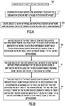
- FIG. 3A a flow chart is shown that depicts the basic operations performed for chaining service zones.
- a route target, RT is assigned for each service zone. This assignment may be made at network management equipment.
- a virtual PE edge router after learning a new route, in each service zone advertises routes by its destination network prefix tagged with its route target.
- a service chain is created chain by importing from destination networks or downstream service zones and exporting of destination network prefixes by way of route targets at virtual PE edge routers of the service zones to upstream service zones or source networks.
- FIG. 3B is a flow chart that shows in more detail the operations performed by edge routers.
- an edge router of the first service zone receives a route advertisement from an edge router of the second service zone or destination network, the route advertisement advertising a destination network prefix of the second service zone or destination network tagged with the route target for the second service zone (or destination network).
- the edge router of the first service zone imports the destination network prefix advertised for the second service zone or destination network based on the route advertisement received from the edge router of the second service zone or destination network.
- the edge router of the first service zone re-originates the imported route from the edge router of the second service zone or destination network such that the edge router of the first service zone sets itself as the forwarding next hop and replaces the route target of the second service zone with the route target for the first service zone for import by a third service zone that is further upstream, with respect to a traffic flow, to the first service zone.
- the re-origination operation involves advertising to an edge router of the third service zone, or source network, a re-originated route advertisement learned from the edge router of the second service zone, the re-originated route advertisement including information indicating the destination network prefix of the second service zone, an address of the edge router for the first service zone as the forwarding next hop and the route target of the first service zone.
- service zone route target re-origination also referred to as VRF installation
- VRF installation the original route advertisement for subnet 2.0.0.0/8 is sent from VPE B with export RT(4) and next hop 3.0.0.4.
- Service Zone Q imports routes at VPE Q using import RT(4).
- VPE Q therefore has 2.0.0.0/8 pointing to next hop (3.0.0.4) which is VPE B.
- VPE Q re-originates subnet 2.0.0.0/8 with itself as next hop (3.0.0.3) and appends RT(3).
- Service Zone P imports routes at VPE P using import RT(3).
- VPE P therefore has 2.0.0.0/8 pointing to next hop 3.0.0.3 which is VPE Q.
- VPE P re-originates subnet 2.0.0.0/8 with itself as next hop 3.0.0.2 and appends RT(2).
- VPE A imports routes using import RT(2).
- VPE A therefore has 2.0.0.0/8 pointing to next hop (3.0.0.2) which is VPE P.
- FIG. 4 shows the chaining together of two service zones between two routed areas.
- the advertisement When a route is re-originated between service zones, the advertisement carries the preferred tunneling mechanism for the aggregate route in the advertisement.
- This tunneling mechanism can be a standard MPLS path, General Routing Encapsulation (GRE), MPLSoIP/GRE, Virtual Extensible LAN (VXLAN) or any other tunneling mechanism. While no specific tunneling mechanism is mandated, the tunnel needs to carry in its header an identifier referring to the next hop's VRF (e.g. a MPLS label or other identifier).
- Inter-service zone routing is by way of aggregate routes to control the amount of signaling. The amount of signaling should be close to none if the configuration is stable, i.e., if there are no routing reconfigurations.
- aggregate routes are distributed, these aggregates can optionally additionally carry protocol-specific parameters for directing certain streams.
- protocol-specific parameters for directing certain streams.
- a tunnel can carry session-specific information to the benefit of subsequent service zones.
- the service instance itself may be integrated with the (virtual) PE to enable the service instance to learn of these extra parameters, or alternatively, the (virtual) PE maintains a tunnel as an attachment circuit to the service instance to carry the extra parameters.
- Traffic routing is based on simple aggregate destination prefix route advertisements. Yet, exceptionally, aggregate source-based routing can be considered as well, albeit this would involve (MP-)BGP standards changes.
- Reconfigurations of the chain can be performed dynamically, although care needs to be taken to avoid creating cycles in a chain.
- routed area X and service zones P and Q connecting to the Internet.
- first VRFs in R need to import routes tagged with RT(P) before routers in service zone Q can import routes tagged with RT(R) and routers in service zone P can import routes tagged with RT(R').
- routers in service zone Q can then stop importing and actively discarding routes tagged with RT(P) while routers in service zone P can stop importing and actively discarding routes tagged with RT(Q).
- first routes between service zone P and service zone Q need to be established before routes through service zone R can be discarded. This is horizontal scaling of the service chain.
- a similar technique is used for inserting default routes.
- an external controller can download aggregate routes into each of the (virtual) PE's VRFs by way of an external interface.
- (Virtual) PEs can be created and dismissed dynamically. While regular routing techniques can be used to distribute aggregate routes through a service area, such as distribution of aggregate routes to previous hops, a (virtual) PE needs to be provisioned with the appropriate (route target) parameters to make this happen.
- Each of the (virtual) PEs can cater to an external interface that allows a central controller to provision the (virtual) PE.
- This central controller is configured for dynamic instantiation of VRFs in the newly created (virtual) PE, installation of the appropriate export and import route targets associated with that VRF, other configuration parameters to enable the (virtual) PE to communicate with other (virtual) PEs. Similarly, the central controller removes the (virtual) PE from the routed infrastructure.
- Cloud management systems can address the actual instantiation of the appropriate virtual machines that carry the virtual PEs and the establishment of attachment circuits.
- FIG. 8 shows an example of a central controller in provisioning and re-configuring VPEs.
- Routing and signaling within a service zone is based on session routing. While inter-zonal communication is based on VRFs, routing and signaling within a service zone is based on "service routing and forwarding" (SRF). For intra-service routing, it is important to list per session which particular virtual appliance using which particular address is serving a particular session. The reason this is important is that oftentimes a service instance allocates "state" to maintain the service. If packets are not guaranteed to be delivered at the same service instance, usually no service can be offered.
- SRF service routing and forwarding
- one or more (virtual) PEs/VRFs in a service zone maintains one or more attachment circuits to one or more service instances.
- attachment circuits can be based on VLAN technology, hypervisor kernel tunnels (e.g. tunctl(8)), virtual Ethernet (e.g. SR-IOV) switching functionality, or other attachment connection types.
- hypervisor kernel tunnels e.g. tunctl(8)
- virtual Ethernet e.g. SR-IOV
- a hypervisor kernel co-resident virtual PE terminates the attachment tunnels to the service instance. In this case, all packets destined to that service need to be routed first to the co-resident (virtual) PE before packets can be delivered to the appropriate service instance.
- Reference numeral 300 is a service zone, and the elements shown in FIG. 5 are elements of the service zone that may be implemented in a data center.
- the data center includes a plurality of server blades each having one or more processor cores and capable of running multiple virtual machines.
- a virtual router 320 runs in a virtual machine on server blade 310 and operates a network interface card (NIC) 322.
- NIC network interface card
- the virtual router 320 is equivalent to the aforementioned service zone edge router referred to in connection with FIG. 2 .
- the server blade 310(1) also stores data structures for each of a plurality of VRFs, for example, VRF 330(1) and 330(2), and VRFs 332(1) and 332(2), labeled as VRF(i), VRF(j), VRF(k) and VRF(1), respectively.
- VRF 330(1) and 330(2) and VRFs 332(1) and 332(2), labeled as VRF(i), VRF(j), VRF(k) and VRF(1), respectively.
- There are individual processor cores 312(1)-312(n) in the data center that each runs a service in a virtual machine. There may be a service running per processor core.
- processor core 312(1) runs service 340 (also called SVC(Q))
- processor core 312(2) runs another instance of the same service 340
- processor core 312(n) runs service 342 (also called SVC(P)).
- attachment circuit 350(1) connects traffic from VRF(i) to SVC(Q) in processor cores 312(1) and 312(2).
- Attachment circuit 350(2) connects traffic from VRF(k) to SVC(P) in processor core 312(n).
- Attachment circuit 350(3) connects traffic (after processing by SVC(P)) from SVC(P) to VRF(1) and attachment circuit 350(4) connects traffic (after processing by SVC(Q)) from SVC(Q) in processor cores 312(1) and 312(2) to VRF(j).
- the server blade 310(1) stores a data structure for each of the VRFs.
- Each VRF contains information as to how to switch a packet into a service.
- the VRFs 330(1) and 330(2) are companion VRFs with respect to traffic flow in either direction through the service zone and likewise the VRFs 332(1) and 332(2) are companion VRFs.
- FIG. 5 shows a single service zone, but any given service zone may be part of a chain of other service zones. Accordingly, FIG. 5 shows arrows 360 and 362 to indicate traffic through the service zone 300 associated with two different service chains, denoted Chain X and Chain Y respectively.
- the virtual router 320 will receive, from a third party, over a tunnel (e.g., an MPLS tunnel) an IP packet encapsulated with a header.
- a tunnel e.g., an MPLS tunnel
- Inside the header is a label that refers to a particular VRF in the VRF data structure stored in the server blade 310(1).
- the VRF 330(1) inspects the IP address of the packet and forwards the packet to the appropriate service, e.g., SVC(Q). Information is stored to indicate which of the SVC(Q) instances (on processor core 312(1) or on processor core 312(2)) is serving the IP address for that packet.
- VRF 330(2) receives the packet after it has been processed by SVC(Q)and forwards it out the service zone as appropriate.
- VRFs 332(1) and 332(2) operate in a similar manner for traffic on Chain X.
- VRF 330(2) learns over Chain Y that it has reachability to a particular downstream network, two things can happen. First, the VRF 330(2) leaks that information to its companion VRF 330(1) which can then re-originate that network address. Second, within each of the SRFs, state is maintained as to how to route individual traffic flows, bidirectionally for the service chains. More generally information is stored indicating which service each SRF should forward traffic to based on the particular packet flow of traffic (e.g., IP address of the traffic session). This operation is referred to as session routing within a service zone.
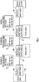
- FIG. 6 a flow chart is shown that depicts the operation of the SRF function and the VRF functions in a service zone.
- a plurality of VRF functions are provided in the (virtual) PE edge router at which traffic is received in a particular service zone and a plurality of attachment circuits are connected between VRF functions and service instances.
- Each VRF function stores data maintaining a corresponding one of the attachment circuits for traffic flow to and from a corresponding service instance.
- the SRF function stores in a session table session information and in combination with the associated VRF which attachment circuits to use, as stored by the VRF data structures, for purposes of directing traffic received at the (virtual) PE edge router of the particular service zone to service instances and receiving traffic back from the service instances.
- the session information represents assignment of packet sessions to attachment circuits for delivery to service instances according to session flow parameters of the packets.
- a VRF function of an (virtual) PE edge router of the particular service zone receives packets.
- the VRF function resolves attachment circuit forwarding information through the packets and the SRF function.
- the SRF function matches session flow parameters, e.g., the 5-tuple of the packets against session information stored in the session table, and passes the packets packet to the VRF function with appropriate session information.
- the VRF function forwards the packets over attachment circuits to service instances according to the session information.
- traffic is received at an edge router in a particular service zone.
- the traffic is directed to a service instance in the particular service zone.
- the traffic is received back from the service instance in the particular service zone and forwarded on from the particular service zone.
- a service zone may comprise a plurality of service instances, and in which case it is necessary to determine which of the plurality of service instances to direct the traffic to in the particular service zone.
- the operations of FIG. 6 described above set forth the mechanism for determining how traffic is directed to service instances within a service zone..
- an HTTP service zone can have many individual virtual HTTP service instances, and the forwarding of the individual sessions to the appropriate HTTP service instance is managed through the VPE/VRF/SRF tables operating in the service zone.
- FIG. 7 an example of the SRF and VRF functions are described.
- FIG. 7 is similar to FIG. 4 in that it has Service Zones P and Q and Routed Areas A and B.
- VPEs 260-266 are provided as described above in connection with FIG. 4 .
- a TCP packet from source 4.0.0.1:333 destined to 2.0.0.1 port 80 is received at VPE A.
- inbound VRF at VPE A has a forwarding entry for 2.0.0.0/8 referring to next hop 3.0.0.2 which is VPE P.
- the packet is forwarded to VPE P.
- VPE P uses the SRF function and information in the session information table 525 to forward the packet.
- An entry in the session information table 525 is found matching source 4.0.0.1, destination port 80, which refers to VM address 10.0.0.2 that is reachable via attachment circuit VLAN12.
- the packet is forwarded to VM with address 10.0.0.2 which is VM (PI).
- the return packet from VM (PI) is forwarded by VPE P based on lookup in VRF function at VPE P.
- VPE P determines that destination 2.0.0.0/8 is reachable via next hop (3.0.0.3) which is VPE Q.
- the inbound packet at VPE Q is forwarded based on VRF function entry at 545 for destination 2.0.0.0/8 which is next hop (3.0.0.4) which is VPE B.
- SRF state needs to be distributed in the service zone to ensure all SRF functions can route packets to the appropriate service instances.
- This disclosure does not dictate any particular form of service-zone session state management.
- SRF state management systems in a single system. The following are options for SRF session-state information distribution.
- one mechanism to distribute session-state is to use an external controller that installs service routes in all of the VPEs/SRFs as soon as a new service flow is admitted in a service zone.
- the SRF informs the central controller of the new session, the controller makes a service instance placement decision and informs all SRFs of the routing decision.
- FIG. 8 shows a controller 600 connected to a physical server 610 in a data center.
- the physical server 610 may have any number of processing cores running virtual machines, including virtual machines for a plurality of VPEs as shown at reference numerals 620(1)-520(n).
- the controller 600 may be a physical server or software process on a server that is part of a cloud management system.
- the controller 600 sends to the VPE VMs 520(1)-520(n) configuration messages including session state information.
- the controller 600 may perform the aforementioned functions for creating and dismissing virtual PEs, i.e., dynamic instantiation of VRFs in the newly created (virtual) PE, installation of the appropriate export and import route targets associated with that VRF, other configuration parameters to enable the (virtual) PE to communicate with other (virtual) PEs.
- any the aforementioned 5-typle or any part of a packet's IP packet header can be used as a session key.
- source routing only a source address of an IP packet helps direct packet flows.
- more header fields can be used including, but not limited to, protocol types, protocol numbers and destination address ranges (e.g. to route all traffic from 2.1.0/24 to http://cnn.com to a particular service chain).
- the 3GPP General Packet Radio Service (GPRS) tunneling protocol's (GTP) tunnel identifier (TEID) may be used as (part of) a session key, or in case session routing is to be defined for IEEE WiMAX, 3GPP2's CDMA2000/EvDO or cable CAPWAP systems, the generic routing encapsulation (GRE) key may be used as part of the session-routing key.
- GPRS General Packet Radio Service
- GTP General Packet Radio Service
- TEID tunnel identifier
- GRE generic routing encapsulation
- route installation proceeds more "lazily."
- the SRF function matches the session key to the listed session and if it fails to find session routing information, the SRF function requests the installation of a route associated with the session key. If the controller deems the packet to be part of a new session, the controller selects a service instance to host the session, and informs the calling SRF function of the session mapping. If the packet is part of an already existing session, the controller informs the calling SRF function which SRF function is serving the session.
- the SRF functions are operated as a distributed service. All SRFs participating in the service zone may execute a state distribution protocol to inform other participants of local session routing decisions. As an example, if a service instance receives an incoming first packet of a session, it may unilaterally decide which service instance hosts the session, including itself. It then distributes this decision to all or part of the other participants in the service zone by way of, e.g., reliable multicast or piggybacking this information on existing routing protocols such as MP-BGP.
- a (virtual) PE may solicit mapping information first from other participants in the service zone and if no other (virtual) PE supports the mapping, the (virtual) PE may proceed in making a local session routing decision.
- the decision as to if and what state to distribute to other participants is based on the service zone's session-state reliability requirements. In some cases, losing session-routing state is not an issue and no redundancy may be needed. In other cases, it is vital that all SRF functions are completely synchronized, requiring different state consistency protocols.
- service zone session routing state can be kept in a distributed hash table (DHT), where a "primary" SRF function installs routes, and if needed, "secondary" SRF functions can load session-routing state.
- DHT distributed hash table
- Yet another possibility is to completely statically establish a session routing infrastructure to avoid any session-state consistency protocol.
- a simple time-out mechanism may be used to clear SRF entries.
- Each service zone can dynamically adjust its routing, forwarding and service capacity by instantiation of new service instances and virtual PE routers with associated VRF functions and SRF functions.
- regular routing techniques are used to signal adjacency with respect to its VRF function.
- a new virtual PE/VRF When a new virtual PE/VRF is provisioned with the appropriate route targets, it becomes part of the routing infrastructure. It learns of next hops by way of importing the appropriate route targets of next hops, and re-originates those learned routes to previous hops. Session-routing state in the SRF functions is learned by an external controller downloading all session routes into the new instance, or by using distributed reconciliation procedures.
- a virtual PE is simply removed from the set. Again, VRF adjacency state is automatically adjusted, and since SRF state is consistent within the zone, the SRF can be simply discarded. If a service instance itself is discarded, all sessions pointing to the service instance are discarded as well.
- the aforementioned external interface to a (virtual) PE can be used to instruct a (virtual) PE how to manage the SRF functions in a service zone.
- Parameters that can be installed on the (virtual) PEs are the methods by which SRF functions in the service zone maintain consistency, including establishing parameters reflective of MP-BGP parameters, DHT information, multicast tree information or any other parameter needed for this consistency management.
- application-specific parameters may be gleaned from a traffic flow, and there is application-specific functionality available in a (virtual) PE, application-specific parameters may be used for session-routing purposes. This may include HTTP parameters.
- HTTP parameters may include HTTP parameters.
- the data structures associated with maintaining session keys are application specific.
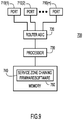
- FIG. 9 an example block diagram is shown for a router configured to perform the operations described herein for an edge router, e.g., (virtual) PE router.
- a virtual PE would be a software-emulated or virtualized version of what is shown in FIG. 9 .
- the PE router shown at reference numeral 700, comprises a plurality of ports 710(1)-710(m), a router Application Specific Integrated Circuit (ASIC) 620, a processor or central processing unit (CPU) 730 and memory 740.
- the ports 710(1)-710(m) receive ingress packets and output egress packets from the router.
- the router ASIC 720 directs incoming packets to ports for egress according to routing logic as well as controls from the processor 730.
- the processor 730 is a microprocessor or microcontroller, for example, and executes instructions for the service zone chaining firmware/software 750 stored in memory 740.
- the service zone chaining firmware/software 750 includes instructions that, when executed by the processor 730, cause the processor to perform the operations described herein in connection with FIGs. 1-8 for a PE router.
- the memory 740 may comprise read only memory (ROM), random access memory (RAM), magnetic disk storage media devices, optical storage media devices, flash memory devices, electrical, optical, or other physical/tangible memory storage devices.
- ROM read only memory
- RAM random access memory
- magnetic disk storage media devices such as magnetic disks
- optical storage media devices such as magnetic tapes
- flash memory devices such as electrical, optical, or other physical/tangible memory storage devices.
- the memory 740 may comprise one or more tangible (non-transitory) computer readable storage media (e.g., a memory device) encoded with software comprising computer executable instructions and when the software is executed (by the processor 740) it is operable to perform the operations described herein.
Landscapes
- Engineering & Computer Science (AREA)
- Computer Networks & Wireless Communication (AREA)
- Signal Processing (AREA)
- Computing Systems (AREA)
- Theoretical Computer Science (AREA)
- Data Exchanges In Wide-Area Networks (AREA)
Claims (11)
- Verfahren, umfassend:Bereitstellen von einer oder mehr Dienstzonen (100, 120) in einer Netzwerkumgebung (10), wobei jede Dienstzone mehrere Instanzen eines Inline-Anwendungsdienstes (110, 130), die auf Netzwerkverkehr angewendet werden sollen, und einen oder mehrere Router (112, 114, 116, 122, 124, 126), um Netzwerkverkehr zu den mehreren Diensten zu leiten, beinhaltet;Zuordnen eines Routenziels zu jeder Dienstzone, um als ein Gemeinschaftswert für Routenimport und -export zwischen Routern von anderen Dienstzonen, Zielnetzwerken oder Quellnetzwerken zu dienen, mittels eines Steuerprotokolls (200) ;Annoncieren von Routen durch einen Edge-Router (116, 126) in jeder Dienstzone oder jedem Zielnetzwerk durch seine Zielnetzwerkvorwahl, die mit seinem Routenziel markiert ist (210) ;Erstellen einer Dienstkette durch Importieren und Exportieren von Zielnetzwerkvorwahlen mithilfe von Routenzielen an Edge-Routern der Dienstzonen oder Quellnetzwerke (220); undBestimmen, an welche der mehreren Inline-Anwendungsdienstinstanzen in der bestimmten Dienstzone Verkehr geleitet werden soll; wobei das Verfahren weiterhin Folgendes umfasst:Bereitstellen mehrerer virtueller Routing- und Weiterleitungsfunktionen (VRF-Funktionen) in dem Edge-Router, an dem Verkehr in einer bestimmten Dienstzone empfangen wird und mehrere Anschlussschaltungen (118, 128) zwischen VRF-Funktionen und Inline-Anwendungsdienstinstanzen angeschlossen sind, wobei jede VRF-Funktion Daten speichert, die eine entsprechende der Anschlussschaltungen für Verkehrsfluss zu und von einer entsprechenden Inline-Anwendungsdienstinstanz aufrechterhalten; undBereitstellen einer Sitzungsrouting- und - weiterleitungsfunktion (SRF-Funktion), die Sitzungsinformationen speichert, um auszuwählen, welche Anschlussschaltungen, wie durch die VRF-Funktionen gespeichert, zum Zwecke des Leitens von Verkehr, der an dem Edge-Router der bestimmten Dienstzone empfangen wird, zu Inline-Anwendungsdienstinstanzen und des Empfangens von Verkehr zurück von den Inline-Anwendungsdienstinstanzen verwendet werden sollen, wobei die Sitzungsinformationen eine Zuordnung von Paketsitzungen zu Anschlussschaltungen zur Lieferung an Inline-Anwendungsdienstinstanzen gemäß Sitzungsflussparametern der Pakete darstellen.
- Verfahren nach Anspruch 1, weiterhin umfassend:
Neuhervorbringen einer importierten Route von einer zweiten Dienstzone oder einem Zielnetzwerk an einem Edge-Router einer ersten Dienstzone, so dass der Edge-Router der ersten Dienstzone sich selbst als den weiterleitenden nächsten Hop einstellt und das Routenziel der zweiten Dienstzone durch das Routenziel für die erste Dienstzone zum Import durch eine dritte Dienstzone ersetzt, die in Bezug auf einen Verkehrsfluss weiter stromaufwärts von der ersten Dienstzone ist (250). - Verfahren nach Anspruch 2, wobei das Erstellen einer Dienstkette Folgendes umfasst:Empfangen einer Routenannonce von einem Edge-Router der zweiten Dienstzone oder des Zielnetzwerks an dem Edge-Router der ersten Dienstzone, wobei die Routenannonce eine Zielnetzwerkvorwahl der zweiten Dienstzone oder des Zielnetzwerks annonciert, die mit dem Routenziel für die zweite Dienstzone markiert ist (230); undImportieren der Zielnetzwerkvorwahl, die für die zweite Dienstzone oder das Zielnetzwerk auf der Basis der Routenannonce, die von dem Edge-Router der zweiten Dienstzone empfangen wurde, annonciert wurde, an dem Edge-Router der ersten Dienstzone (240).
- Verfahren nach Anspruch 3, wobei das Neuhervorbringen Folgendes umfasst:
Annoncieren einer neu hervorgebrachten Routenannonce, die von dem Edge-Router der zweiten Dienstzone gelernt wurde, gegenüber einem Edge-Router der dritten Dienstzone oder des Quellnetzwerks, wobei die neu hervorgebrachte Routenannonce Informationen beinhaltet, die die Zielnetzwerkvorwahl der zweiten Dienstzone, eine Adresse des Edge-Routers für die erste Dienstzone als den weiterleitenden nächsten Hop und das Routenziel der ersten Dienstzone angeben. - Verfahren nach Anspruch 3, wobei die Edge-Router der Dienstzonen physikalische Router oder virtuelle Router sind.
- Verfahren nach Anspruch 1, weiterhin umfassend:Empfangen von Verkehr an einem Edge-Router in einer bestimmten Dienstzone;Leiten des Verkehrs zu einer Dienstinstanz in der bestimmten Dienstzone;Empfangen von Verkehr zurück von der Dienstinstanz in der bestimmten Dienstzone; undWeiterleiten des Verkehrs von der bestimmten Dienstzone.
- Verfahren nach Anspruch 1, wobei das Empfangen von Verkehr das Empfangen von Paketen an einer VRF-Funktion des Edge-Routers der bestimmten Dienstzone (410) umfasst, wobei das Leiten Folgendes umfasst:Übermitteln der Pakete an die SRF-Funktion (420);Abgleichen von Sitzungsflussparametern der Pakete mit den Sitzungsinformationen durch die SRF-Funktion (430);Übermitteln der Pakete zurück an die VRF-Funktion mit geeigneten Sitzungsinformationen; undWeiterleiten von Paketen über Anschlussschaltungen an Dienstinstanzen gemäß den Sitzungsinformationen durch die VRF-Funktion (440).
- Edge-Router (700), umfassend:mehrere Ports (710), die dazu konfiguriert sind, Pakete von einem Netzwerk zu empfangen und ausgegebene Pakete an ein Netzwerk zu senden;eine Router-Einheit, die mit den mehreren Ports gekoppelt ist und dazu konfiguriert ist, Entscheidungen dahingehend zu treffen, wie empfangene Pakete zu Ports zur Ausgabe an das Netzwerk geroutet werden sollen;einen Prozessor (730), der mit der Router-Einheit gekoppelt ist, wobei der Prozessor zu Folgendem konfiguriert ist:Annoncieren von Routen durch eine Zielnetzwerkvorwahl, die mit einem Routenziel für eine Dienstzone oder ein Zielnetzwerk in einer Netzwerkumgebung (10), die eine oder mehr Dienstzonen umfasst, markiert ist, wobei jede Dienstzone mehrere Instanzen eines Inline-Anwendungsdienstes (110, 130), die auf Netzwerkverkehr angewendet werden sollen, und ein Routenziel, das zu jeder einzelnen Dienstzone, um als ein Gemeinschaftswert für Routenimport und -export zwischen Routern (112, 114, 116, 122, 124, 126) von anderen Dienstzonen, Zielnetzwerken oder Quellnetzwerken zu dienen, mittels eines Steuerprotokolls zugeordnet wurde, beinhaltet; undErstellen einer Dienstkette durch Importieren und Exportieren von Zielnetzwerkvorwahlen mithilfe von Routenzielen an Edge-Routern der Dienstzonen oder der Quellnetzwerke, wobei der Prozessor weiterhin dazu konfiguriert ist, zu bestimmen, an welche der mehreren Inline-Anwendungsdienstinstanzen in der bestimmten Dienstzone Verkehr geleitet werden soll, wobei der Prozessor weiterhin zu Folgendem konfiguriert ist:Bereitstellen mehrerer virtueller Routing- und Weiterleitungsfunktionen (VRF-Funktionen) in dem Edge-Router, an dem Verkehr in einer bestimmten Dienstzone empfangen wird, und mehrerer Anschlussschaltungen (118, 128), die zwischen VRF-Funktionen und Inline-Anwendungsdienstinstanzen angeschlossen sind, wobei jede VRF-Funktion Daten speichert, die eine entsprechende der Anschlussschaltungen für Verkehrsfluss zu und von einer entsprechenden Inline-Anwendungsdienstinstanz aufrechterhalten; undBereitstellen einer Sitzungsrouting- und - weiterleitungsfunktion (SRF-Funktion), die Sitzungsinformationen speichert, um auszuwählen, welche Anschlussschaltungen, wie durch die VRF-Funktionen gespeichert, zum Zwecke des Leitens von Verkehr, der an dem Edge-Router der bestimmten Dienstzone empfangen wird, zu Inline-Anwendungsdienstinstanzen und des Empfangens von Verkehr zurück von den Inline-Anwendungsdienstinstanzen verwendet werden sollen, wobei die Sitzungsinformationen eine Zuordnung von Paketsitzungen zu Anschlussschaltungen zur Lieferung an Inline-Anwendungsdienstinstanzen gemäß Sitzungsflussparametern der Pakete darstellen.
- Vorrichtung nach Anspruch 8, wobei der Prozessor weiterhin dazu konfiguriert ist, ein Verfahren nach einem der Ansprüche 2 bis 7 durchzuführen.
- Ein oder mehr computerlesbare Speichermedien, die mit Software codiert sind, die computerausführbare Anweisungen umfasst und zu Folgendem betreibbar ist, wenn die Software ausgeführt wird:Annoncieren von Routen durch eine Zielnetzwerkvorwahl, die mit einem Routenziel für eine Dienstzone oder ein Zielnetzwerk in einer Netzwerkumgebung (10), die eine oder mehr Dienstzonen umfasst, markiert ist, wobei jede Dienstzone mehrere Instanzen eines Inline-Anwendungsdienstes (110, 130), die auf Netzwerkverkehr angewendet werden sollen, und ein Routenziel, das zu jeder einzelnen Dienstzone, um als ein Gemeinschaftswert für Routenimport und -export zwischen Routern (112, 114, 116, 122, 124, 126) von anderen Dienstzonen, Zielnetzwerken oder Quellnetzwerken zu dienen, mittels eines Steuerprotokolls zugeordnet wurde, beinhaltet; undErstellen einer Dienstkette durch Importieren und Exportieren von Zielnetzwerkvorwahlen mithilfe von Routenzielen an Edge-Routern der Dienstzonen oder Quellnetzwerke, wobei die computerlesbaren Speichermedien weiterhin Anweisungen umfassen, die dazu betreibbar sind, zu bestimmen, an welche der mehreren Inline-Anwendungsdienstinstanzen in der bestimmten Dienstzone Verkehr geleitet werden soll, wobei die computerlesbaren Speichermedien Anweisungen umfassen, die zu Folgendem betreibbar sind:Ausführen von mehreren virtuellen Routing- und Weiterleitungsfunktionen (VRF-Funktionen), wobei jede VRF-Funktion Daten speichert, die eine entsprechende von mehreren Anschlussschaltungen für Verkehrsfluss zu und von einer entsprechenden Inline-Anwendungsdienstinstanz aufrechterhalten; undAusführen einer Sitzungsrouting- und - weiterleitungsfunktion (SRF-Funktion), die Sitzungsinformationen speichert, um auszuwählen, welche Anschlussschaltungen, wie durch die VRF-Funktionen gespeichert, zum Zwecke des Leitens von Verkehr, der an dem Edge-Router der bestimmten Dienstzone empfangen wird, zu Inline-Anwendungsdienstinstanzen und des Empfangens von Verkehr zurück von den Inline-Anwendungsdienstinstanzen verwendet werden sollen, wobei die Sitzungsinformationen eine Zuordnung von Paketsitzungen zu Anschlussschaltungen zur Lieferung an Inline-Anwendungsdienstinstanzen gemäß Sitzungsflussparametern der Pakete darstellen.
- Computerlesbare Speichermedien nach Anspruch 10, die weiterhin Anweisungen umfassen, die dazu betreibbar sind, ein Verfahren nach einem der Ansprüche 2 bis 7 durchzuführen.
Applications Claiming Priority (2)
| Application Number | Priority Date | Filing Date | Title |
|---|---|---|---|
| US13/898,932 US9826025B2 (en) | 2013-05-21 | 2013-05-21 | Chaining service zones by way of route re-origination |
| PCT/US2014/036907 WO2014189670A1 (en) | 2013-05-21 | 2014-05-06 | Chaining service zones by way of route re-origination |
Publications (2)
| Publication Number | Publication Date |
|---|---|
| EP3000206A1 EP3000206A1 (de) | 2016-03-30 |
| EP3000206B1 true EP3000206B1 (de) | 2018-07-11 |
Family
ID=50896566
Family Applications (1)
| Application Number | Title | Priority Date | Filing Date |
|---|---|---|---|
| EP14728777.5A Not-in-force EP3000206B1 (de) | 2013-05-21 | 2014-05-06 | Verkettung von dienstzonen durch routenneuorganisation |
Country Status (4)
| Country | Link |
|---|---|
| US (2) | US9826025B2 (de) |
| EP (1) | EP3000206B1 (de) |
| CN (1) | CN105247822B (de) |
| WO (1) | WO2014189670A1 (de) |
Families Citing this family (62)
| Publication number | Priority date | Publication date | Assignee | Title |
|---|---|---|---|---|
| US8743885B2 (en) | 2011-05-03 | 2014-06-03 | Cisco Technology, Inc. | Mobile service routing in a network environment |
| US9088584B2 (en) | 2011-12-16 | 2015-07-21 | Cisco Technology, Inc. | System and method for non-disruptive management of servers in a network environment |
| US9225638B2 (en) | 2013-05-09 | 2015-12-29 | Vmware, Inc. | Method and system for service switching using service tags |
| US9509614B2 (en) | 2013-06-20 | 2016-11-29 | Cisco Technology, Inc. | Hierarchical load balancing in a network environment |
| US9374297B2 (en) | 2013-12-17 | 2016-06-21 | Cisco Technology, Inc. | Method for implicit session routing |
| EP3116177B1 (de) * | 2014-03-24 | 2020-02-26 | Huawei Technologies Co. Ltd. | Dienstimplementierungsverfahren für nfv-system und kommunikationseinheiten |
| US9813258B2 (en) * | 2014-03-31 | 2017-11-07 | Tigera, Inc. | Data center networks |
| US9344364B2 (en) * | 2014-03-31 | 2016-05-17 | Metaswitch Networks Ltd. | Data center networks |
| US9559950B2 (en) * | 2014-03-31 | 2017-01-31 | Tigera, Inc. | Data center networks |
| US9379931B2 (en) | 2014-05-16 | 2016-06-28 | Cisco Technology, Inc. | System and method for transporting information to services in a network environment |
| US9479443B2 (en) | 2014-05-16 | 2016-10-25 | Cisco Technology, Inc. | System and method for transporting information to services in a network environment |
| US20150381418A1 (en) * | 2014-06-27 | 2015-12-31 | iPhotonix | Remote Orchestration of Virtual Machine Updates |
| US9794172B2 (en) * | 2014-06-27 | 2017-10-17 | iPhotonix | Edge network virtualization |
| US9979698B2 (en) | 2014-06-27 | 2018-05-22 | iPhotonix | Local internet with quality of service (QoS) egress queuing |
| US10135737B2 (en) | 2014-09-30 | 2018-11-20 | Nicira, Inc. | Distributed load balancing systems |
| US9755898B2 (en) | 2014-09-30 | 2017-09-05 | Nicira, Inc. | Elastically managing a service node group |
| US10225137B2 (en) | 2014-09-30 | 2019-03-05 | Nicira, Inc. | Service node selection by an inline service switch |
| US10417025B2 (en) | 2014-11-18 | 2019-09-17 | Cisco Technology, Inc. | System and method to chain distributed applications in a network environment |
| US9531850B2 (en) * | 2014-12-04 | 2016-12-27 | Cisco Technology, Inc. | Inter-domain service function chaining |
| US20160173392A1 (en) * | 2014-12-15 | 2016-06-16 | Tieto Oyj | Service Chain Management |
| US9584415B2 (en) * | 2015-01-30 | 2017-02-28 | Huawei Technologies Co., Ltd. | Devices, systems and methods for service chains |
| US10924298B2 (en) * | 2015-02-11 | 2021-02-16 | Hewlett Packard Enterprise Development Lp | Network service chain construction |
| US9736063B2 (en) * | 2015-02-17 | 2017-08-15 | Huawei Technologies Co., Ltd. | Service chaining using source routing |
| US10609091B2 (en) | 2015-04-03 | 2020-03-31 | Nicira, Inc. | Method, apparatus, and system for implementing a content switch |
| US9853898B1 (en) * | 2015-04-29 | 2017-12-26 | Juniper Networks, Inc. | Dynamic service chain provisioning |
| US9762402B2 (en) | 2015-05-20 | 2017-09-12 | Cisco Technology, Inc. | System and method to facilitate the assignment of service functions for service chains in a network environment |
| US10103976B2 (en) | 2015-07-09 | 2018-10-16 | Cisco Technology, Inc. | Service bitmask-based service application in service function chaining |
| US9723106B2 (en) | 2015-08-28 | 2017-08-01 | Cisco Technology, Inc. | Service function chaining branching |
| US11044203B2 (en) | 2016-01-19 | 2021-06-22 | Cisco Technology, Inc. | System and method for hosting mobile packet core and value-added services using a software defined network and service chains |
| US10164875B2 (en) * | 2016-02-22 | 2018-12-25 | Cisco Technology, Inc. | SR app-segment integration with service function chaining (SFC) header metadata |
| CN105978806B (zh) * | 2016-03-11 | 2019-03-26 | 北京星网锐捷网络技术有限公司 | 一种服务链引流方法和装置 |
| CN105912266A (zh) * | 2016-04-05 | 2016-08-31 | 浪潮电子信息产业股份有限公司 | 一种刀片服务器及一种刀片服务器的融合存储的方法 |
| US10498765B2 (en) * | 2016-06-01 | 2019-12-03 | At&T Intellectual Property I, L.P. | Virtual infrastructure perimeter regulator |
| US10079767B2 (en) | 2016-06-13 | 2018-09-18 | Cisco Technology, Inc. | Multi-mobile core networks and value-added services |
| CN106169980A (zh) * | 2016-06-29 | 2016-11-30 | 国家计算机网络与信息安全管理中心 | 一种虚拟网络带宽公平调度方法 |
| US10158565B2 (en) * | 2016-08-26 | 2018-12-18 | Cisco Technology, Inc. | Network services across non-contiguous subnets of a label switched network separated by a non-label switched network |
| US11277338B2 (en) * | 2016-09-26 | 2022-03-15 | Juniper Networks, Inc. | Distributing service function chain data and service function instance data in a network |
| US10250500B2 (en) | 2016-12-30 | 2019-04-02 | Juniper Networks, Inc. | Performing a service on a packet |
| US10805181B2 (en) | 2017-10-29 | 2020-10-13 | Nicira, Inc. | Service operation chaining |
| US11012420B2 (en) | 2017-11-15 | 2021-05-18 | Nicira, Inc. | Third-party service chaining using packet encapsulation in a flow-based forwarding element |
| US10797910B2 (en) | 2018-01-26 | 2020-10-06 | Nicira, Inc. | Specifying and utilizing paths through a network |
| US10659252B2 (en) | 2018-01-26 | 2020-05-19 | Nicira, Inc | Specifying and utilizing paths through a network |
| US10728174B2 (en) | 2018-03-27 | 2020-07-28 | Nicira, Inc. | Incorporating layer 2 service between two interfaces of gateway device |
| US10805192B2 (en) | 2018-03-27 | 2020-10-13 | Nicira, Inc. | Detecting failure of layer 2 service using broadcast messages |
| US11595250B2 (en) | 2018-09-02 | 2023-02-28 | Vmware, Inc. | Service insertion at logical network gateway |
| US10944673B2 (en) | 2018-09-02 | 2021-03-09 | Vmware, Inc. | Redirection of data messages at logical network gateway |
| CN110971522B (zh) * | 2018-09-30 | 2021-09-17 | 华为技术有限公司 | 一种确定路由泄露的方法、设备和系统 |
| CN111200549B (zh) * | 2018-11-16 | 2021-04-20 | 华为技术有限公司 | 一种获取路由信息的方法及装置 |
| JP7081521B2 (ja) * | 2019-02-06 | 2022-06-07 | 日本電信電話株式会社 | 通信システムおよび通信方法 |
| US11086654B2 (en) | 2019-02-22 | 2021-08-10 | Vmware, Inc. | Providing services by using multiple service planes |
| US11140218B2 (en) | 2019-10-30 | 2021-10-05 | Vmware, Inc. | Distributed service chain across multiple clouds |
| US11283717B2 (en) | 2019-10-30 | 2022-03-22 | Vmware, Inc. | Distributed fault tolerant service chain |
| US11223494B2 (en) | 2020-01-13 | 2022-01-11 | Vmware, Inc. | Service insertion for multicast traffic at boundary |
| US11659061B2 (en) | 2020-01-20 | 2023-05-23 | Vmware, Inc. | Method of adjusting service function chains to improve network performance |
| US11153406B2 (en) | 2020-01-20 | 2021-10-19 | Vmware, Inc. | Method of network performance visualization of service function chains |
| US11438257B2 (en) | 2020-04-06 | 2022-09-06 | Vmware, Inc. | Generating forward and reverse direction connection-tracking records for service paths at a network edge |
| US11456955B2 (en) | 2020-04-16 | 2022-09-27 | Juniper Networks, Inc. | Tenant-based mapping for virtual routing and forwarding |
| CN114363183A (zh) * | 2020-09-30 | 2022-04-15 | 中兴通讯股份有限公司 | 一种业务链地址池切片处理方法、装置及系统 |
| US11611625B2 (en) | 2020-12-15 | 2023-03-21 | Vmware, Inc. | Providing stateful services in a scalable manner for machines executing on host computers |
| US11734043B2 (en) | 2020-12-15 | 2023-08-22 | Vmware, Inc. | Providing stateful services in a scalable manner for machines executing on host computers |
| US12413500B2 (en) * | 2021-02-04 | 2025-09-09 | Nokia Solutions And Networks Oy | Service differentiation based on constrained network topology slicing |
| US20260106825A1 (en) * | 2024-10-11 | 2026-04-16 | Cisco Technology, Inc. | Border gateway protocol message monitoring system |
Family Cites Families (44)
| Publication number | Priority date | Publication date | Assignee | Title |
|---|---|---|---|---|
| US20020150094A1 (en) * | 2000-10-27 | 2002-10-17 | Matthew Cheng | Hierarchical level-based internet protocol multicasting |
| US20030128668A1 (en) * | 2002-01-04 | 2003-07-10 | Yavatkar Rajendra S. | Distributed implementation of control protocols in routers and switches |
| CN1183726C (zh) * | 2002-08-05 | 2005-01-05 | 华为技术有限公司 | 基于多协议标签交换虚拟私有网络网关的组网方法 |
| US7245640B2 (en) * | 2002-12-18 | 2007-07-17 | Intel Corporation | Packet origination |
| US9137033B2 (en) * | 2003-03-18 | 2015-09-15 | Dynamic Network Services, Inc. | Methods and systems for monitoring network routing |
| US20050289244A1 (en) * | 2004-06-28 | 2005-12-29 | Himansu Sahu | Method for service chaining in a communication network |
| US7643468B1 (en) | 2004-10-28 | 2010-01-05 | Cisco Technology, Inc. | Data-center network architecture |
| US20060092950A1 (en) | 2004-10-28 | 2006-05-04 | Cisco Technology, Inc. | Architecture and method having redundancy in active/active stateful devices based on symmetric global load balancing protocol (sGLBP) |
| US20060095960A1 (en) | 2004-10-28 | 2006-05-04 | Cisco Technology, Inc. | Data center topology with transparent layer 4 and layer 7 services |
| US7558261B2 (en) | 2004-10-28 | 2009-07-07 | Cisco Technology, Inc. | Architecture and method for accessing services in a data center |
| US7610375B2 (en) | 2004-10-28 | 2009-10-27 | Cisco Technology, Inc. | Intrusion detection in a data center environment |
| US7571470B2 (en) | 2004-10-28 | 2009-08-04 | Cisco Technology, Inc. | One arm data center topology with layer 4 and layer 7 services |
| US7657940B2 (en) | 2004-10-28 | 2010-02-02 | Cisco Technology, Inc. | System for SSL re-encryption after load balance |
| US7616574B2 (en) * | 2005-03-15 | 2009-11-10 | Cisco Technology, Inc. | Dynamic retrieval of routing information for inter-AS TE-LSPs |
| US20060291446A1 (en) * | 2005-06-24 | 2006-12-28 | Donald Caldwell | Systems, methods, and devices for managing routing |
| JP2007067505A (ja) * | 2005-08-29 | 2007-03-15 | Nippon Telegr & Teleph Corp <Ntt> | エッジノードおよびコアノード |
| US7554996B2 (en) * | 2005-09-14 | 2009-06-30 | Cisco Technology, Inc. | Controlled distribution of inter-area routing information |
| US9015299B1 (en) * | 2006-01-20 | 2015-04-21 | Cisco Technology, Inc. | Link grouping for route optimization |
| US8311045B2 (en) | 2006-04-07 | 2012-11-13 | Cisco Technology, Inc. | System and method for selectively applying a service to a network packet using a preexisting packet header |
| US9253274B2 (en) | 2007-01-19 | 2016-02-02 | Cisco Technology, Inc. | Service insertion architecture |
| US9432213B2 (en) * | 2007-12-31 | 2016-08-30 | Rpx Clearinghouse Llc | IP forwarding across a link state protocol controlled ethernet network |
| FR2934450A1 (fr) * | 2008-07-23 | 2010-01-29 | France Telecom | Distribution de routes dans un reseau de routeurs. |
| US7916729B2 (en) * | 2008-09-30 | 2011-03-29 | Cisco Technology, Inc. | Automatic RD rewrite technique to achieve fast convergence in inter-as networks |
| US8442043B2 (en) | 2008-12-29 | 2013-05-14 | Cisco Technology, Inc. | Service selection mechanism in service insertion architecture data plane |
| EP2249525B1 (de) * | 2009-05-06 | 2012-10-31 | Alcatel Lucent | Aufbau einer Traffic-Engineered-Verbindung über Ressourcendomains zum Datentransport |
| KR101584603B1 (ko) * | 2009-11-10 | 2016-01-14 | 노키아 솔루션스 앤드 네트웍스 오와이 | 통신 트래픽 브레이크아웃을 제공하기 위한 통신 네트워크의 네트워크 디바이스 및 방법 |
| EP2537299B1 (de) * | 2010-02-16 | 2022-03-23 | Transpacific IP Group Limited | Verwaltung privater virtueller netzwerke |
| CN102195855B (zh) * | 2010-03-17 | 2014-10-08 | 华为技术有限公司 | 一种业务路由方法和业务网络 |
| US8504718B2 (en) * | 2010-04-28 | 2013-08-06 | Futurewei Technologies, Inc. | System and method for a context layer switch |
| CN102143199A (zh) * | 2010-10-19 | 2011-08-03 | 华为技术有限公司 | 获取内容的方法、节点及内容网络 |
| US8700801B2 (en) * | 2010-12-01 | 2014-04-15 | Juniper Networks, Inc. | Dynamically generating application-layer traffic optimization protocol maps |
| US8806032B2 (en) * | 2010-12-15 | 2014-08-12 | At&T Intellectual Property I, L.P. | Methods and apparatus to migrate border gateway protocol sessions between routers |
| US8954491B1 (en) * | 2010-12-30 | 2015-02-10 | Juniper Networks, Inc. | Dynamically generating application-layer traffic optimization protocol endpoint attributes |
| US8559414B2 (en) * | 2011-02-19 | 2013-10-15 | Cisco Technology, Inc. | Automatically detecting best paths from shadow route reflectors |
| US8824471B2 (en) * | 2011-06-01 | 2014-09-02 | Cisco Technology, Inc. | Maintained message delivery during routing domain migration |
| US9491686B2 (en) * | 2011-07-28 | 2016-11-08 | Pulse Secure, Llc | Virtual private networking with mobile communication continuity |
| US20130028140A1 (en) * | 2011-07-28 | 2013-01-31 | Cisco Technology, Inc. | Using service discovery to build routing topologies |
| US20140376371A1 (en) * | 2012-01-02 | 2014-12-25 | Nokia Solutions And Networks Oy | Method and Device for Conveying Data Across at Least Two Domains |
| US9106555B2 (en) * | 2012-01-25 | 2015-08-11 | Cisco Technology, Inc. | Troubleshooting routing topology based on a reference topology |
| US8891450B2 (en) * | 2012-02-06 | 2014-11-18 | Juniper Networks, Inc. | Mobile node host route installation and withdrawal |
| US20130219046A1 (en) * | 2012-02-21 | 2013-08-22 | Cisco Technology, Inc. | Dynamic application-aware routing topologies |
| US10097452B2 (en) * | 2012-04-16 | 2018-10-09 | Telefonaktiebolaget Lm Ericsson (Publ) | Chaining of inline services using software defined networking |
| US9130977B2 (en) * | 2012-04-18 | 2015-09-08 | Radware, Ltd. | Techniques for separating the processing of clients' traffic to different zones |
| WO2014169251A1 (en) * | 2013-04-12 | 2014-10-16 | Huawei Technologies Co., Ltd. | Service chain policy for distributed gateways in virtual overlay networks |
-
2013
- 2013-05-21 US US13/898,932 patent/US9826025B2/en active Active
-
2014
- 2014-05-06 EP EP14728777.5A patent/EP3000206B1/de not_active Not-in-force
- 2014-05-06 WO PCT/US2014/036907 patent/WO2014189670A1/en not_active Ceased
- 2014-05-06 CN CN201480029433.8A patent/CN105247822B/zh not_active Expired - Fee Related
-
2017
- 2017-09-21 US US15/711,235 patent/US10270843B2/en not_active Expired - Fee Related
Non-Patent Citations (1)
| Title |
|---|
| None * |
Also Published As
| Publication number | Publication date |
|---|---|
| US10270843B2 (en) | 2019-04-23 |
| EP3000206A1 (de) | 2016-03-30 |
| US20180013821A1 (en) | 2018-01-11 |
| WO2014189670A1 (en) | 2014-11-27 |
| US9826025B2 (en) | 2017-11-21 |
| US20140351452A1 (en) | 2014-11-27 |
| CN105247822B (zh) | 2018-09-18 |
| CN105247822A (zh) | 2016-01-13 |
Similar Documents
| Publication | Publication Date | Title |
|---|---|---|
| US10270843B2 (en) | Chaining service zones by way of route re-origination | |
| US10986024B1 (en) | Dynamic prefix list for route filtering | |
| US10992577B2 (en) | Auto discovery and auto scaling of services in software-defined network environment | |
| EP3745658B1 (de) | Netzwerkübergreifende dienstverkettung | |
| US11956141B2 (en) | Service chaining with physical network functions and virtualized network functions | |
| US10454821B2 (en) | Creating and maintaining segment routed traffic engineering policies via border gateway protocol | |
| US9634936B2 (en) | Service chaining across multiple networks | |
| EP3834365B1 (de) | Versionierung des multicast-verteilungsbaums zur minimierung von multicast-gruppenverkehrsunterbrechungen | |
| WO2016197344A1 (zh) | 实现业务链接的方法、设备及系统 | |
| EP3151477B1 (de) | Schneller pfad für inhaltsbereitstellung über metro-zugangsnetze | |
| US20200314016A1 (en) | Tunneling inter-domain stateless internet protocol multicast packets | |
| WO2020230146A1 (en) | Method and apparatus for layer 2 route calculation in a route reflector network device | |
| US11611506B2 (en) | Processing a flow at the egress node in segment routing |
Legal Events
| Date | Code | Title | Description |
|---|---|---|---|
| PUAI | Public reference made under article 153(3) epc to a published international application that has entered the european phase |
Free format text: ORIGINAL CODE: 0009012 |
|
| 17P | Request for examination filed |
Effective date: 20150917 |
|
| AK | Designated contracting states |
Kind code of ref document: A1 Designated state(s): AL AT BE BG CH CY CZ DE DK EE ES FI FR GB GR HR HU IE IS IT LI LT LU LV MC MK MT NL NO PL PT RO RS SE SI SK SM TR |
|
| AX | Request for extension of the european patent |
Extension state: BA ME |
|
| DAX | Request for extension of the european patent (deleted) | ||
| REG | Reference to a national code |
Ref country code: DE Ref legal event code: R079 Ref document number: 602014028282 Country of ref document: DE Free format text: PREVIOUS MAIN CLASS: H04L0012715000 Ipc: H04L0012751000 |
|
| GRAP | Despatch of communication of intention to grant a patent |
Free format text: ORIGINAL CODE: EPIDOSNIGR1 |
|
| STAA | Information on the status of an ep patent application or granted ep patent |
Free format text: STATUS: GRANT OF PATENT IS INTENDED |
|
| RIC1 | Information provided on ipc code assigned before grant |
Ipc: H04L 29/08 20060101ALI20171211BHEP Ipc: H04L 12/751 20130101AFI20171211BHEP Ipc: H04L 12/715 20130101ALI20171211BHEP |
|
| INTG | Intention to grant announced |
Effective date: 20180102 |
|
| GRAS | Grant fee paid |
Free format text: ORIGINAL CODE: EPIDOSNIGR3 |
|
| GRAA | (expected) grant |
Free format text: ORIGINAL CODE: 0009210 |
|
| STAA | Information on the status of an ep patent application or granted ep patent |
Free format text: STATUS: THE PATENT HAS BEEN GRANTED |
|
| AK | Designated contracting states |
Kind code of ref document: B1 Designated state(s): AL AT BE BG CH CY CZ DE DK EE ES FI FR GB GR HR HU IE IS IT LI LT LU LV MC MK MT NL NO PL PT RO RS SE SI SK SM TR |
|
| REG | Reference to a national code |
Ref country code: GB Ref legal event code: FG4D |
|
| REG | Reference to a national code |
Ref country code: CH Ref legal event code: EP |
|
| REG | Reference to a national code |
Ref country code: AT Ref legal event code: REF Ref document number: 1018080 Country of ref document: AT Kind code of ref document: T Effective date: 20180715 |
|
| REG | Reference to a national code |
Ref country code: IE Ref legal event code: FG4D |
|
| REG | Reference to a national code |
Ref country code: DE Ref legal event code: R096 Ref document number: 602014028282 Country of ref document: DE |
|
| REG | Reference to a national code |
Ref country code: NL Ref legal event code: MP Effective date: 20180711 |
|
| REG | Reference to a national code |
Ref country code: LT Ref legal event code: MG4D |
|
| REG | Reference to a national code |
Ref country code: AT Ref legal event code: MK05 Ref document number: 1018080 Country of ref document: AT Kind code of ref document: T Effective date: 20180711 |
|
| PG25 | Lapsed in a contracting state [announced via postgrant information from national office to epo] |
Ref country code: NL Free format text: LAPSE BECAUSE OF FAILURE TO SUBMIT A TRANSLATION OF THE DESCRIPTION OR TO PAY THE FEE WITHIN THE PRESCRIBED TIME-LIMIT Effective date: 20180711 |
|
| PG25 | Lapsed in a contracting state [announced via postgrant information from national office to epo] |
Ref country code: NO Free format text: LAPSE BECAUSE OF FAILURE TO SUBMIT A TRANSLATION OF THE DESCRIPTION OR TO PAY THE FEE WITHIN THE PRESCRIBED TIME-LIMIT Effective date: 20181011 Ref country code: GR Free format text: LAPSE BECAUSE OF FAILURE TO SUBMIT A TRANSLATION OF THE DESCRIPTION OR TO PAY THE FEE WITHIN THE PRESCRIBED TIME-LIMIT Effective date: 20181012 Ref country code: SE Free format text: LAPSE BECAUSE OF FAILURE TO SUBMIT A TRANSLATION OF THE DESCRIPTION OR TO PAY THE FEE WITHIN THE PRESCRIBED TIME-LIMIT Effective date: 20180711 Ref country code: FI Free format text: LAPSE BECAUSE OF FAILURE TO SUBMIT A TRANSLATION OF THE DESCRIPTION OR TO PAY THE FEE WITHIN THE PRESCRIBED TIME-LIMIT Effective date: 20180711 Ref country code: PL Free format text: LAPSE BECAUSE OF FAILURE TO SUBMIT A TRANSLATION OF THE DESCRIPTION OR TO PAY THE FEE WITHIN THE PRESCRIBED TIME-LIMIT Effective date: 20180711 Ref country code: LT Free format text: LAPSE BECAUSE OF FAILURE TO SUBMIT A TRANSLATION OF THE DESCRIPTION OR TO PAY THE FEE WITHIN THE PRESCRIBED TIME-LIMIT Effective date: 20180711 Ref country code: RS Free format text: LAPSE BECAUSE OF FAILURE TO SUBMIT A TRANSLATION OF THE DESCRIPTION OR TO PAY THE FEE WITHIN THE PRESCRIBED TIME-LIMIT Effective date: 20180711 Ref country code: IS Free format text: LAPSE BECAUSE OF FAILURE TO SUBMIT A TRANSLATION OF THE DESCRIPTION OR TO PAY THE FEE WITHIN THE PRESCRIBED TIME-LIMIT Effective date: 20181111 Ref country code: AT Free format text: LAPSE BECAUSE OF FAILURE TO SUBMIT A TRANSLATION OF THE DESCRIPTION OR TO PAY THE FEE WITHIN THE PRESCRIBED TIME-LIMIT Effective date: 20180711 Ref country code: BG Free format text: LAPSE BECAUSE OF FAILURE TO SUBMIT A TRANSLATION OF THE DESCRIPTION OR TO PAY THE FEE WITHIN THE PRESCRIBED TIME-LIMIT Effective date: 20181011 |
|
| PG25 | Lapsed in a contracting state [announced via postgrant information from national office to epo] |
Ref country code: ES Free format text: LAPSE BECAUSE OF FAILURE TO SUBMIT A TRANSLATION OF THE DESCRIPTION OR TO PAY THE FEE WITHIN THE PRESCRIBED TIME-LIMIT Effective date: 20180711 Ref country code: AL Free format text: LAPSE BECAUSE OF FAILURE TO SUBMIT A TRANSLATION OF THE DESCRIPTION OR TO PAY THE FEE WITHIN THE PRESCRIBED TIME-LIMIT Effective date: 20180711 Ref country code: LV Free format text: LAPSE BECAUSE OF FAILURE TO SUBMIT A TRANSLATION OF THE DESCRIPTION OR TO PAY THE FEE WITHIN THE PRESCRIBED TIME-LIMIT Effective date: 20180711 Ref country code: HR Free format text: LAPSE BECAUSE OF FAILURE TO SUBMIT A TRANSLATION OF THE DESCRIPTION OR TO PAY THE FEE WITHIN THE PRESCRIBED TIME-LIMIT Effective date: 20180711 |
|
| REG | Reference to a national code |
Ref country code: DE Ref legal event code: R097 Ref document number: 602014028282 Country of ref document: DE |
|
| PG25 | Lapsed in a contracting state [announced via postgrant information from national office to epo] |
Ref country code: EE Free format text: LAPSE BECAUSE OF FAILURE TO SUBMIT A TRANSLATION OF THE DESCRIPTION OR TO PAY THE FEE WITHIN THE PRESCRIBED TIME-LIMIT Effective date: 20180711 Ref country code: CZ Free format text: LAPSE BECAUSE OF FAILURE TO SUBMIT A TRANSLATION OF THE DESCRIPTION OR TO PAY THE FEE WITHIN THE PRESCRIBED TIME-LIMIT Effective date: 20180711 Ref country code: RO Free format text: LAPSE BECAUSE OF FAILURE TO SUBMIT A TRANSLATION OF THE DESCRIPTION OR TO PAY THE FEE WITHIN THE PRESCRIBED TIME-LIMIT Effective date: 20180711 Ref country code: IT Free format text: LAPSE BECAUSE OF FAILURE TO SUBMIT A TRANSLATION OF THE DESCRIPTION OR TO PAY THE FEE WITHIN THE PRESCRIBED TIME-LIMIT Effective date: 20180711 |
|
| PLBE | No opposition filed within time limit |
Free format text: ORIGINAL CODE: 0009261 |
|
| STAA | Information on the status of an ep patent application or granted ep patent |
Free format text: STATUS: NO OPPOSITION FILED WITHIN TIME LIMIT |
|
| PG25 | Lapsed in a contracting state [announced via postgrant information from national office to epo] |
Ref country code: SK Free format text: LAPSE BECAUSE OF FAILURE TO SUBMIT A TRANSLATION OF THE DESCRIPTION OR TO PAY THE FEE WITHIN THE PRESCRIBED TIME-LIMIT Effective date: 20180711 Ref country code: SM Free format text: LAPSE BECAUSE OF FAILURE TO SUBMIT A TRANSLATION OF THE DESCRIPTION OR TO PAY THE FEE WITHIN THE PRESCRIBED TIME-LIMIT Effective date: 20180711 Ref country code: DK Free format text: LAPSE BECAUSE OF FAILURE TO SUBMIT A TRANSLATION OF THE DESCRIPTION OR TO PAY THE FEE WITHIN THE PRESCRIBED TIME-LIMIT Effective date: 20180711 |
|
| 26N | No opposition filed |
Effective date: 20190412 |
|
| PG25 | Lapsed in a contracting state [announced via postgrant information from national office to epo] |
Ref country code: SI Free format text: LAPSE BECAUSE OF FAILURE TO SUBMIT A TRANSLATION OF THE DESCRIPTION OR TO PAY THE FEE WITHIN THE PRESCRIBED TIME-LIMIT Effective date: 20180711 |
|
| REG | Reference to a national code |
Ref country code: CH Ref legal event code: PL |
|
| PG25 | Lapsed in a contracting state [announced via postgrant information from national office to epo] |
Ref country code: LI Free format text: LAPSE BECAUSE OF NON-PAYMENT OF DUE FEES Effective date: 20190531 Ref country code: CH Free format text: LAPSE BECAUSE OF NON-PAYMENT OF DUE FEES Effective date: 20190531 Ref country code: MC Free format text: LAPSE BECAUSE OF FAILURE TO SUBMIT A TRANSLATION OF THE DESCRIPTION OR TO PAY THE FEE WITHIN THE PRESCRIBED TIME-LIMIT Effective date: 20180711 |
|
| REG | Reference to a national code |
Ref country code: BE Ref legal event code: MM Effective date: 20190531 |
|
| PG25 | Lapsed in a contracting state [announced via postgrant information from national office to epo] |
Ref country code: LU Free format text: LAPSE BECAUSE OF NON-PAYMENT OF DUE FEES Effective date: 20190506 |
|
| PG25 | Lapsed in a contracting state [announced via postgrant information from national office to epo] |
Ref country code: TR Free format text: LAPSE BECAUSE OF FAILURE TO SUBMIT A TRANSLATION OF THE DESCRIPTION OR TO PAY THE FEE WITHIN THE PRESCRIBED TIME-LIMIT Effective date: 20180711 |
|
| PG25 | Lapsed in a contracting state [announced via postgrant information from national office to epo] |
Ref country code: IE Free format text: LAPSE BECAUSE OF NON-PAYMENT OF DUE FEES Effective date: 20190506 |
|
| PG25 | Lapsed in a contracting state [announced via postgrant information from national office to epo] |
Ref country code: BE Free format text: LAPSE BECAUSE OF NON-PAYMENT OF DUE FEES Effective date: 20190531 |
|
| PG25 | Lapsed in a contracting state [announced via postgrant information from national office to epo] |
Ref country code: PT Free format text: LAPSE BECAUSE OF FAILURE TO SUBMIT A TRANSLATION OF THE DESCRIPTION OR TO PAY THE FEE WITHIN THE PRESCRIBED TIME-LIMIT Effective date: 20181111 |
|
| PG25 | Lapsed in a contracting state [announced via postgrant information from national office to epo] |
Ref country code: CY Free format text: LAPSE BECAUSE OF FAILURE TO SUBMIT A TRANSLATION OF THE DESCRIPTION OR TO PAY THE FEE WITHIN THE PRESCRIBED TIME-LIMIT Effective date: 20180711 |
|
| PG25 | Lapsed in a contracting state [announced via postgrant information from national office to epo] |
Ref country code: MT Free format text: LAPSE BECAUSE OF FAILURE TO SUBMIT A TRANSLATION OF THE DESCRIPTION OR TO PAY THE FEE WITHIN THE PRESCRIBED TIME-LIMIT Effective date: 20180711 Ref country code: HU Free format text: LAPSE BECAUSE OF FAILURE TO SUBMIT A TRANSLATION OF THE DESCRIPTION OR TO PAY THE FEE WITHIN THE PRESCRIBED TIME-LIMIT; INVALID AB INITIO Effective date: 20140506 |
|
| PGFP | Annual fee paid to national office [announced via postgrant information from national office to epo] |
Ref country code: FR Payment date: 20210510 Year of fee payment: 8 Ref country code: DE Payment date: 20210520 Year of fee payment: 8 |
|
| PGFP | Annual fee paid to national office [announced via postgrant information from national office to epo] |
Ref country code: GB Payment date: 20210511 Year of fee payment: 8 |
|
| REG | Reference to a national code |
Ref country code: DE Ref legal event code: R079 Ref document number: 602014028282 Country of ref document: DE Free format text: PREVIOUS MAIN CLASS: H04L0012751000 Ipc: H04L0045020000 |
|
| PG25 | Lapsed in a contracting state [announced via postgrant information from national office to epo] |
Ref country code: MK Free format text: LAPSE BECAUSE OF FAILURE TO SUBMIT A TRANSLATION OF THE DESCRIPTION OR TO PAY THE FEE WITHIN THE PRESCRIBED TIME-LIMIT Effective date: 20180711 |
|
| REG | Reference to a national code |
Ref country code: DE Ref legal event code: R119 Ref document number: 602014028282 Country of ref document: DE |
|
| GBPC | Gb: european patent ceased through non-payment of renewal fee |
Effective date: 20220506 |
|
| PG25 | Lapsed in a contracting state [announced via postgrant information from national office to epo] |
Ref country code: FR Free format text: LAPSE BECAUSE OF NON-PAYMENT OF DUE FEES Effective date: 20220531 |
|
| PG25 | Lapsed in a contracting state [announced via postgrant information from national office to epo] |
Ref country code: GB Free format text: LAPSE BECAUSE OF NON-PAYMENT OF DUE FEES Effective date: 20220506 Ref country code: DE Free format text: LAPSE BECAUSE OF NON-PAYMENT OF DUE FEES Effective date: 20221201 |
|
| P01 | Opt-out of the competence of the unified patent court (upc) registered |
Effective date: 20230525 |