EP2999623B1 - A suction anchor, a composite module segment for a suction anchor and a method for assembling such segments - Google Patents
A suction anchor, a composite module segment for a suction anchor and a method for assembling such segments Download PDFInfo
- Publication number
- EP2999623B1 EP2999623B1 EP14788522.2A EP14788522A EP2999623B1 EP 2999623 B1 EP2999623 B1 EP 2999623B1 EP 14788522 A EP14788522 A EP 14788522A EP 2999623 B1 EP2999623 B1 EP 2999623B1
- Authority
- EP
- European Patent Office
- Prior art keywords
- surface portion
- contact surface
- caisson
- segment
- anchor
- Prior art date
- Legal status (The legal status is an assumption and is not a legal conclusion. Google has not performed a legal analysis and makes no representation as to the accuracy of the status listed.)
- Active
Links
Images





Classifications
-
- B—PERFORMING OPERATIONS; TRANSPORTING
- B63—SHIPS OR OTHER WATERBORNE VESSELS; RELATED EQUIPMENT
- B63B—SHIPS OR OTHER WATERBORNE VESSELS; EQUIPMENT FOR SHIPPING
- B63B21/00—Tying-up; Shifting, towing, or pushing equipment; Anchoring
- B63B21/24—Anchors
- B63B21/26—Anchors securing to bed
- B63B21/27—Anchors securing to bed by suction
-
- B—PERFORMING OPERATIONS; TRANSPORTING
- B63—SHIPS OR OTHER WATERBORNE VESSELS; RELATED EQUIPMENT
- B63B—SHIPS OR OTHER WATERBORNE VESSELS; EQUIPMENT FOR SHIPPING
- B63B21/00—Tying-up; Shifting, towing, or pushing equipment; Anchoring
- B63B21/50—Anchoring arrangements or methods for special vessels, e.g. for floating drilling platforms or dredgers
-
- E—FIXED CONSTRUCTIONS
- E02—HYDRAULIC ENGINEERING; FOUNDATIONS; SOIL SHIFTING
- E02D—FOUNDATIONS; EXCAVATIONS; EMBANKMENTS; UNDERGROUND OR UNDERWATER STRUCTURES
- E02D27/00—Foundations as substructures
- E02D27/32—Foundations for special purposes
- E02D27/52—Submerged foundations, i.e. submerged in open water
-
- E—FIXED CONSTRUCTIONS
- E02—HYDRAULIC ENGINEERING; FOUNDATIONS; SOIL SHIFTING
- E02D—FOUNDATIONS; EXCAVATIONS; EMBANKMENTS; UNDERGROUND OR UNDERWATER STRUCTURES
- E02D7/00—Methods or apparatus for placing sheet pile bulkheads, piles, mouldpipes, or other moulds
- E02D7/28—Placing of hollow pipes or mould pipes by means arranged inside the piles or pipes
-
- E—FIXED CONSTRUCTIONS
- E02—HYDRAULIC ENGINEERING; FOUNDATIONS; SOIL SHIFTING
- E02B—HYDRAULIC ENGINEERING
- E02B17/00—Artificial islands mounted on piles or like supports, e.g. platforms on raisable legs or offshore constructions; Construction methods therefor
- E02B2017/0056—Platforms with supporting legs
- E02B2017/0073—Details of sea bottom engaging footing
- E02B2017/0078—Suction piles, suction cans
Definitions
- the present invention relates to a modular composite suction anchor for mooring purposes.
- Suction caissons, suction anchors or suction moorings is well known technology used for mooring oil related installations, floating wind mills, subsea installations etc. to a soft sea bed.
- Suction anchors are convenient as they are removable, and provide reliable attachment points.
- a suction anchor includes a caisson or suction caisson, hereinafter only caisson with an open end and a closed end, and some attachment arrangement at the closed end.
- suction anchors are lowered to the sea bed and water is pumped out of the caisson such that the pressure differences between the outside and the inside of the caisson drives the anchor into the sea bed.
- the anchor may be released from the sea bed by pumping water into the caisson.
- Suction anchors are commonly made of large diameter steel tubing that is relatively heavy and cumbersome to install. Furthermore, solutions including steel tubing are difficult to provide in different sizes and must be transported in their full size.
- Suction anchors may form a part of unitary subsea production equipment that is lowered onto the seabed from a vessel, and four suction anchors are typically used.
- the anchors are normally made of steel of sufficient gauge or thickness to allow for corrosion, and the thickness will depend on the anticipated lifespan of the installation.
- the anchors constitute a high percentage of the overall weight of the installation. The weight of the installation dictates the classification/allowable load of an installation vessel.
- suction anchor that is easy to transport, as the suction anchor can be transported in parts or can be filled with buoyant media and floated in place.
- suction anchor that is cost effective to manufacture in high numbers and in different sizes.
- Weight saving that will allow for the use of a smaller vessel will result in considerable installation savings and increased availability of installation vessels.
- composite suction anchors can reduce the weight of suction anchors typically to between one half and one third of the weight of comparable steel suction anchors and the potential for economic savings is considerable.
- the weight saving may result in more allowable weight for more useful components of an installation where the anchors are includes.
- the expected lifespan of the suction anchors is independent of corrosion.
- the present invention defines a suction anchor for providing a foundation or mooring attachment on a soft sea bed.
- the suction anchor includes a caisson with an open bottom portion, a closed top portion and a side portion defining a first outer surface with a substantially constant outer perimeter along a sea bed immersing height.
- the seabed immersing height is the height of the suction anchor, or the inserted design depth of the anchor into the seabed.
- the suction anchor defines an inner volume, and means are provided for allowing water to be pumped out of the inner volume. These means may include some sort of sealable opening, a valve that may be stabbed by a ROV or any other structure that allows water to be pumped into or out of the volume.
- the suction anchor includes at least two adjoining caisson module segments with an inner surface and an outer surface forming a part of the first outer surface. Each caisson module segment extends at least along said immersing height. Each caisson module segment furthermore includes a contact surface portion on the outer surface, joint with a contact surface portion on an outer surface of an adjoining module.
- the caisson module segments are made of a composite material. A load attachment portion is secured to the closed top portion.
- a first and a second contact surface portion may be located on said outer surface at each side of said outer surface portion of each caisson module segment respectively.
- the first module contact surface portion may include a male assembly guide, and the second module contact surface portion may include a female assembly guide.
- the first contact surface portion may be formed as a rib and the second contact surface portion may be formed as a rib and the contact surface portion may then adjoin a contact surface portion of an adjacent element in a center a stiffening rib of the suction anchor.
- the first contact surface portion may be formed as a male rib with a male assembly guide and the second contact surface portion may be formed as a female rib with a female assembly guide.
- the suction anchor may further include at least one structural anchor cavity formed into at least one stiffening rib, and a structural anchor in said least one structural anchor cavity whereby said at least one structural anchor is embedded in said at least one stiffening rib.
- the first contact surface portion is formed as a male rib with a male assembly guide and the second contact surface portion is formed as a female rib with a female assembly guide.
- the composite caisson module segment may further include a structural anchor cavity formed in said outer surface the first contact surface portion on the first side of the exposed surface portion and/or the second contact surface portion on the second side of the exposed surface portion.
- the contact surface portion may adjoin a contact surface portion of an adjacent caisson module segment in a center of a stiffening rib of the suction anchor.
- the suction anchor may include six caisson module segments.
- the invention concerns a composite caisson module segment for a suction anchor.
- the caisson module segment includes a side portion defining an outer surface with a substantially constant outer perimeter along a sea bed immersing height, an inner surface and an outer surface, and a module contact surface portion on the outer surface.
- a first and a second contact surface portion may be located on said outer surface at each side of said outer surface portion of each caisson module segment respectively.
- the first module contact surface portion may include a male assembly guide, and the second module contact surface portion may include a female assembly guide.
- the invention concerns a method for assembling a suction anchor of composite caisson module segments comprising the steps of providing a first composite caisson module segment with a substantially constant outer perimeter along a sea bed immersing height (h i ), said composite caisson module segment including an inner surface and an outer surface, wherein the outer surface includes a first contact surface portion on a first side of an exposed surface portion and a second contact surface portion on a second side of the exposed surface portion, providing a second caisson module segment substantially similar to the first composite caisson module segment, joining the first contact surface portion on the first composite caisson module segment with the second contact surface portion of the second caisson module segment, and continue providing caisson module segments and joining first contact surface portions and second contact surface portions of adjoining caisson module segment until a complete caisson is formed.
- Fig. 1 shows a suction caisson, suction anchor or suction mooring according to the invention, in the following referred to as anchor 1.
- the anchor 1 includes a metal load attachment portion 2, including an attachment flange 3, secured to a modular composite portion or caisson.
- the modular composite portion is assembled of segmented caisson module segments 4, 5 joined in module joints 7.
- Fig. 1 shows plain caisson module segments 4 and fluid connection caisson module segments 5 with connection portions 6 for connection to a pump and for pumping water in or out of the caisson.
- the caisson has a cylindrical outer shape and curved transition portion 11 that forms a transition to a flat end portion 10.
- the curved transition portion 11 between the cylindrical outer shape and the flat end portion 10 ensures stress distribution in the composite caisson.
- the flat end portion 10 provides an attachment area for the attachment flange 3.
- a side portion defines first outer surface 23 with a substantially constant outer perimeter along a sea bed immersing height h i .
- the immersing height h i represents the design penetration depth of the suction anchor into the seabed.
- a first outer surface 23, is a combination of external surfaces of each caisson module segment 4, 5.
- Fig. 2 shows the caisson from below, where the cylindrical shape is clearly visible.
- the open bottom of the caisson allows the anchor to be filled with soft sea bed when water is pumped out of at least one of the connection openings 6 in the two fluid connection caisson module segments 5.
- the plain caisson module segments 4 are similar to the fluid connection caisson module segments 5 apart from the missing connection openings 6.
- the connection openings 6 may be sealed off when they not are connected to a pump unit to maintain a pressure difference between the inside and the outside of the caisson when the anchor is loaded with some load.
- the suction anchor / caisson define an inner volume 24.
- the caisson module segments define an inner surface 22.
- Fig. 2 shows six caisson module segments assembled in module joints 8 forming the segment joints 7.
- Each caisson module segment 4, 5 is formed with a segment rib 12 at each side of a curved portion forming a part of the cylindrical outer shape of the caisson.
- each caisson defines a 60° arc shaped wall portion and segmented rib portions 12 at each side of the arc shaped wall portion.
- the rib portions 12 are extending in an inward radial direction in relation to the arc shaped wall portion.
- the rib portions 12 of each caisson module segment 4, 5 form faces for ease of assembly, in that the rib portions of each caisson module may be joined with the neighbouring caisson module.
- the rib portions provide ample area for adhesive bonding / moulding of the caisson module segments and for assembly of the caisson.
- the rib portions 12 facilitate formation of sealed joints between the modules and improve rigidity of the assembled caisson. Furthermore, the rib portions 12 provide a considerable increase of seabed contact area and thus in holding friction, increasing the holding ability of the suction anchor.
- Fig. 2 furthermore shows the bottom flange 9 that forms a base for bolts holding the attachment flange to the bottom flange and for stress distribution of the load from the attachment portion.
- the bottom flange includes radial notches to allow the ribs to extend through the bottom flange.
- Fig. 3 is a top view of the anchor of the invention.
- the six assembled caisson module segments 4, 5, including the fluid connection caisson module segments 5 with connection openings 6, form a cylindrical outer face that is joined in segment joints 7.
- the attachment flange 3 with the load attachment portion 2 is secured to the flat end portion 10 of the caisson.
- the rounded transition 15 extends between the cylindrical portion and the flat end portion 10.
- Fig. 4 and fig. 5 show a top view of a fluid connection caisson module segment 5 and a plain caisson module segment 4 respectively.
- the fluid connection caisson module segment 5 includes the sealable connection opening 6.
- a curved transition portion 11 is formed between the arch shaped portion forming a part of the cylindrical caisson and the flat end portion 10.
- Each caisson module segment 4, 5 include a male rib 12b with a male assembly guide 14 and a female rib 12b with a female assembly guide.
- the male assembly guide 14 of each caisson module is intended to extend into the female assembly guide of the adjacent caisson module to ease correct assembly of the caisson.
- each module segment is divided into three separate outer surfaces 23p, 23b, 23c whereof a center surface / exposed surface portion 23p forms a part of the outer surface 23 of the caisson.
- Contact surface portions 23b, 23c are located on each side of the exposed outer surface portion 23p for assembly and contact with the contact surface 23b, 23c on an outer surface of an adjoining module.
- the flat end portion10 forms a flange attachment portion 16 with flange bolt holes 19 for flange bolts extending through the bottom flange and the attachment flange.
- the flange attachment to all the caisson module segments reduces the stress on the joint interface between the modules.
- Fig. 6 shows a cross section of a caisson module of the embodiment shown in the other figures, and clearly shows the arch shaped outer portion 21, the female segment rib 12a and the male segment rib 12b.
- the caisson module is shown with a 60° arch, but this angle will depend on the number of caisson module segments that form the caisson.
- the inwards extending radial ribs 12a, 12b are formed with the male assembly guide 14 and the female assembly guide 13.
- the male assembly guide 14 is designed and dimensioned to extend into the female assembly guide of the neighboring caisson module to ensure proper alignment between the neighboring modules during assembly.
- Fig. 7 shows a cross section of an anchor of the invention with the attachment flange 3 with a load attachment portion 2 and a reinforcing gusset 17 therein between.
- the attachment flange 3 is fixed to the six caisson module segments and the bottom flange 9.
- the segment ribs 12 are shown in dashed lines.
- the curved transition portion 11 between the cylindrical outer portion and the flat end portion 10, ensures stress distribution between the flange and the caisson.
- Fig. 8 shows a detail of the attachment flange 3 with the load attachment portion 2 and the bottom flange 9.
- the flat end portion of all the caisson module segments and hence the caisson is sandwiched between the attachment flange 3 and the bottom flange 9.
- Flange bolts 18 extend through the flat end portion of the caisson, the attachment flange 3 and the bottom flange 9.
- the segment ribs 12 extend toward the flat end portion of the caisson to reinforce the top portion.
- Fig. 9 shows a cross section of an assembly of two caisson modules of fig. 6 of the embodiment shown in the other figures.
- the arch shaped outer portions 21 form a smooth or even arc and a segment rib 12 is joined by a female rib section 12a and a male rib section12b, forming a double rib 12 with twice the wall thickness of the outer wall. This increased wall thickness also increases the rigidity of the assembly.
- the caisson modules are shown with a 60° arch, but this angle will depend on the number of caisson module segments forming the caisson.
- the male assembly guide 14 extends into the conforming female assembly guide 13 to ensure proper alignment between neighboring modules during assembly and contributes to increased stiffness and integrity of the joint.
- a U-shaped locking profile 25 straddles the two ribs 12 for additional stiffness, as a redundant sealing and to maintain the two ribs in an assembled position.
- An adhesive such as epoxy or polyester may be injected into the U-shaped locking profile 25 for added integrity and to form a seal.
- the U-shaped locking profile 25 may typically be made of a composite material or an extruded alloy.
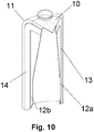
- Fig 10 is a perspective view of a caisson module of the invention with the portion for attachment of an attachment flange.
- the female segment rib 12a and the male segment rib 12b are shown as tapered ribs with increasing width towards the top of the module.
- the curved transition portion 11 between the cylindrical outer portion, the flat end portion 10, and the tapered ribs ensure stress distribution between the flange and the caisson.
- the male assembly guide 14 and the female assembly guide 13 form inverted L-shaped assembly guides to ensure proper alignment of the caisson modules both a longitudinal and a radial direction. Again the rib size contributes to determine the total area of the anchor exposed to the seabed and hence to determine the total friction between the seabed and the anchor.
- the shown embodiment includes a metal load attachment portion 2, including an attachment flange 3, secured to the suction anchor.
- the metal load attachment portion 2 could however be substituted with other attachment elements typically for attaching the suction anchor to subsea installations.
- Such attachment elements could for instance include a ring or cylindrical portion cast into the upper part of the caisson module segments for attachment to a conforming portion of a subsea installation.
- a ring or cylindrical portion could be a part of a metal attachment flange structure corresponding to the one shown in for instance fig. 7 , but where the attachment portion 2 and the gusset 17 are substituted with a part for attachment to a subsea installation.
- the attachment flange also contributes to stiffen and distribute stresses from the load of the element to be anchored to the suction anchor.
- a metal attachment structure may also improve resistance against wear and abrasion between the element to be anchored and the suction anchor itself.
- Fig 11 is a perspective view of an alternative embodiment of a suction anchor of fig. 1 where the metal load attachment portion 2 of fig. 1 is substituted with structural anchor cavities 30 for (a structural anchor is shown on fig. 17 ).
- Reinforcement plates 31 surround openings for the structural anchor cavities 30.
- Each reinforcement plate 31 may be a metal plate embedded in the composite caisson module segments 4 and includes an opening for a structural anchor.
- the remaining features of the suction anchor correspond to the features of the suction anchor of fig. 1 apart from the metal attachment flange shown on fig. 1 .
- Contrary to the embodiment of fig 1 is the flat end portion 10 completely without perforations or openings for bolts and thus completely sealed and not relying on seals around bolts extending through the flat end portion 10.
- the structural anchor cavities 30 will not extend into the internal cavity of the anchor as will be seen on fig. 13 . ;
- Fig. 12 is a top view of the suction anchor of fig. 11 , where the reinforcement plates 31 surrounding the openings for the structural anchor cavities 30 are more clearly shown.
- the reinforcement plates 31 bridges the module joints 7 between the caisson module segments 4 at the flat end portion 10.
- a centre opening may be permanently plugged.
- Fig 13 is a side elevation view of a caisson module segment 4 of the invention for the embodiment shown in fig. 11 and fig. 12 .
- the caisson module segment has the same features as the caisson module segment of fig. 10 , apart from the top bolt holes and the connection openings 6 (shown in for instance fig. 2 ).
- the embodiments shown in the figs. 11-17 may also include similar connection openings.
- the embodiment shows the structural anchor cavity 30 moulded or machined into the rib at the flat portion at the top of the of caisson module segment 4.
- the structural anchor cavity 30 may be formed into one rib completely, or may be formed on mating faces of two adjoining ribs, such that a structural anchor is located for instance midway between two ribs.
- a male segment rib 12b is shown as tapered ribs with increasing width towards the top of the module.
- the curved transition portion between the cylindrical outer portion, the flat end portion, and the tapered ribs ensure stress distribution between the flange and the caisson.
- the rib size contributes to determine the total area of the anchor exposed to the seabed and hence to determine the total friction between the seabed and the anchor.
- the location of the structural anchor cavity 30 there are no holes or openings between the inner and outer surfaces of the suction anchor, an thus that the likelihood of a leak is reduced.
- the location of the structural anchor cavity 30 ensures that forces from a structural anchor is transferred directly to the ribs of each caisson module segment.
- a structural anchor is placed in a structural anchor cavity 30 before two caisson module segments are joined, and the structural anchors become embedded in the ribs joining the caisson module segments.
- Fig. 14 is a perspective view of a third embodiment of a suction anchor 1 according of the invention, installed in a seabed 42.
- the embodiment of fig. 14 corresponds in most ways with the embodiment shown in figs. 11-13 , but an attachment element 35 with structural anchors is located in a module joint 7 in an internal rib, at the side on the cylindrical part of the suction anchor 1.
- a mooring line 36 is attached to the attachment element 35 at a location below the seabed 42.
- the suction anchor 1 of the figs. 14-16 is intended for anchoring inclined mooring lines applying a sideways force component on the suction anchor 1.
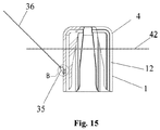
- Fig. 15 is a cross section of a suction anchor according the embodiment of the invention shown on fig. 14 .
- the solution and features shown in fig. 15 corresponds in most ways solution and features shown in with fig 7 , apart from the top flange in fig. 7 and the attachment element 35 of fig. 15 .
- the attachment element 35 is shown embedded between two ribs forming a rib 12 of two adjoining caisson module segments 4 at the cylindrical side of the suction anchor 1 at the lower half of the suction anchor 1.
- the seabed 42 is located at the upper half of the suction anchor 1, leaving the attachment element 35 below the seabed 42.
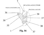
- Fig. 16 is a detail of the cross section of the suction anchor 1 of fig. 15 , and shows the attachment element 35 integrated with two structural anchors 37 embedded in two structural anchor cavities 30.
- the mooring line 36 is attached to a mooring line attachment opening 38 in the attachment element 35.
- Fig. 17 is structural anchor 37 for the suction anchor shown in the figs. 11-16 .
- the structural anchor 37 is formed as a "traditional" boat anchor with transverse portions 30 at a lower end of a center column 39 with a structure attachment portion 41.
- the structure attachment portion 41 will typically be adapted to a structure to be mounted on top of the suction anchor.
- the two transverse portions 40 be inclined or bent somewhat upwards in relation to the centre column 39.
- the structural anchors 37 an the attachment elements 35 are typically made of metal.
- the structural anchor cavity 30 is typically shaped as the structural anchor 37, and the shape of the structural anchor cavity 30 thus conforms to the shape of the structural anchor 37.
- composite is meant to cover fiber reinforced synthetic materials such as glass fibers in a polyester or epoxy matrix.
- Glass fibers are normally considered as the most cost effective solution, as the cost of carbon fibers or Kevlar fibers could be prohibitive.
- Composite is not meant to cover materials such as concrete or steel.
Landscapes
- Engineering & Computer Science (AREA)
- Chemical & Material Sciences (AREA)
- Ocean & Marine Engineering (AREA)
- Mechanical Engineering (AREA)
- Combustion & Propulsion (AREA)
- Paleontology (AREA)
- General Engineering & Computer Science (AREA)
- Structural Engineering (AREA)
- Civil Engineering (AREA)
- Life Sciences & Earth Sciences (AREA)
- Mining & Mineral Resources (AREA)
- General Life Sciences & Earth Sciences (AREA)
- Revetment (AREA)
- Load-Engaging Elements For Cranes (AREA)
- Hooks, Suction Cups, And Attachment By Adhesive Means (AREA)
- Joining Of Building Structures In Genera (AREA)
- Foundations (AREA)
Description
- The present invention relates to a modular composite suction anchor for mooring purposes.
- Suction caissons, suction anchors or suction moorings is well known technology used for mooring oil related installations, floating wind mills, subsea installations etc. to a soft sea bed. Suction anchors are convenient as they are removable, and provide reliable attachment points. A suction anchor includes a caisson or suction caisson, hereinafter only caisson with an open end and a closed end, and some attachment arrangement at the closed end. During installation, suction anchors are lowered to the sea bed and water is pumped out of the caisson such that the pressure differences between the outside and the inside of the caisson drives the anchor into the sea bed. Similarly, the anchor may be released from the sea bed by pumping water into the caisson.
- Suction anchors are commonly made of large diameter steel tubing that is relatively heavy and cumbersome to install. Furthermore, solutions including steel tubing are difficult to provide in different sizes and must be transported in their full size.
- Suction anchors may form a part of unitary subsea production equipment that is lowered onto the seabed from a vessel, and four suction anchors are typically used. The anchors are normally made of steel of sufficient gauge or thickness to allow for corrosion, and the thickness will depend on the anticipated lifespan of the installation. The anchors constitute a high percentage of the overall weight of the installation. The weight of the installation dictates the classification/allowable load of an installation vessel.
- It is a purpose with the present invention to provide a suction anchor solution and a method of assembly that allows simple production of suction anchors with few limitations in size.
- Furthermore, it is a purpose of the present invention to provide a modular suction anchor that is easy to transport, as the suction anchor can be transported in parts or can be filled with buoyant media and floated in place.
- Furthermore, it is a purpose of the present invention to provide a suction anchor that is cost effective to manufacture in high numbers and in different sizes.
- Furthermore it is a purpose of the present invention to provide a suction anchor that is considerably lighter than a steel counterpart.
- Weight saving that will allow for the use of a smaller vessel will result in considerable installation savings and increased availability of installation vessels.
- The use of composite suction anchors can reduce the weight of suction anchors typically to between one half and one third of the weight of comparable steel suction anchors and the potential for economic savings is considerable. Alternatively, the weight saving may result in more allowable weight for more useful components of an installation where the anchors are includes. Furthermore, the expected lifespan of the suction anchors is independent of corrosion.
- The present invention defines a suction anchor for providing a foundation or mooring attachment on a soft sea bed. The suction anchor includes a caisson with an open bottom portion, a closed top portion and a side portion defining a first outer surface with a substantially constant outer perimeter along a sea bed immersing height.
- The seabed immersing height is the height of the suction anchor, or the inserted design depth of the anchor into the seabed.
- The suction anchor defines an inner volume, and means are provided for allowing water to be pumped out of the inner volume. These means may include some sort of sealable opening, a valve that may be stabbed by a ROV or any other structure that allows water to be pumped into or out of the volume. The suction anchor includes at least two adjoining caisson module segments with an inner surface and an outer surface forming a part of the first outer surface. Each caisson module segment extends at least along said immersing height. Each caisson module segment furthermore includes a contact surface portion on the outer surface, joint with a contact surface portion on an outer surface of an adjoining module. The caisson module segments are made of a composite material. A load attachment portion is secured to the closed top portion.
- A first and a second contact surface portion may be located on said outer surface at each side of said outer surface portion of each caisson module segment respectively.
- The first module contact surface portion may include a male assembly guide, and the second module contact surface portion may include a female assembly guide.
- The first contact surface portion may be formed as a rib and the second contact surface portion may be formed as a rib and the contact surface portion may then adjoin a contact surface portion of an adjacent element in a center a stiffening rib of the suction anchor.
- The first contact surface portion may be formed as a male rib with a male assembly guide and the second contact surface portion may be formed as a female rib with a female assembly guide.
- The suction anchor according may further include at least one structural anchor cavity formed into at least one stiffening rib, and a structural anchor in said least one structural anchor cavity whereby said at least one structural anchor is embedded in said at least one stiffening rib.
- The first contact surface portion is formed as a male rib with a male assembly guide and the second contact surface portion is formed as a female rib with a female assembly guide.
- The composite caisson module segment may further include a structural anchor cavity formed in said outer surface the first contact surface portion on the first side of the exposed surface portion and/or the second contact surface portion on the second side of the exposed surface portion.
- The contact surface portion may adjoin a contact surface portion of an adjacent caisson module segment in a center of a stiffening rib of the suction anchor.
- The suction anchor may include six caisson module segments.
- Furthermore, the invention concerns a composite caisson module segment for a suction anchor. The caisson module segment includes a side portion defining an outer surface with a substantially constant outer perimeter along a sea bed immersing height, an inner surface and an outer surface, and a module contact surface portion on the outer surface.
- A first and a second contact surface portion may be located on said outer surface at each side of said outer surface portion of each caisson module segment respectively.
- The first module contact surface portion may include a male assembly guide, and the second module contact surface portion may include a female assembly guide.
- Furthermore, the invention concerns a method for assembling a suction anchor of composite caisson module segments comprising the steps of providing a first composite caisson module segment with a substantially constant outer perimeter along a sea bed immersing height (hi), said composite caisson module segment including an inner surface and an outer surface, wherein the outer surface includes a first contact surface portion on a first side of an exposed surface portion and a second contact surface portion on a second side of the exposed surface portion, providing a second caisson module segment substantially similar to the first composite caisson module segment, joining the first contact surface portion on the first composite caisson module segment with the second contact surface portion of the second caisson module segment, and continue providing caisson module segments and joining first contact surface portions and second contact surface portions of adjoining caisson module segment until a complete caisson is formed.
- Short description of the enclosed drawings:
-
Fig. 1 shows a suction anchor according an embodiment of the invention; -
Fig. 2 is a bottom view of the suction anchor offig. 1 ; -
Fig. 3 is a top view of the suction anchor offig. 1 ; -
Fig. 4 is a top view of a first composite caisson module segment of the invention; -
Fig. 5 is top view of a second composite caisson module segment of the invention; -
Fig. 6 is a cross section of a composite caisson module segment of the invention; -
Fig. 7 is a cross section of a suction anchor according the embodiment of the invention shown onfig. 1 ; -
Fig. 8 shows a detail the cross section shown onfig. 7 ; -
Fig. 9 shows a cross section of an assembly of two caisson modules offig. 6 ; -
Fig 10 is a perspective view of a caisson module of the invention. -
Fig 11 is a perspective view of an alternative embodiment of a suction anchor of the invention; -
Fig. 12 is a top view of the suction anchor offig. 11 ; -
Fig 13 is a side elevation view of a caisson module segment of the invention for the embodiment shown infig. 11 andfig. 12 ; -
Fig. 14 is a perspective view of a third embodiment of a suction anchor according of the invention, installed in a seabed; -
Fig. 15 is a cross section of a suction anchor according the embodiment of the invention shown onfig. 14 ; -
Fig. 16 is a detail of the cross section of the suction anchor offig. 15 ; and -
Fig. 17 is structural anchor for the suction anchors shown of thefigs. 11-16 . - Detailed description of an embodiment of the invention with reference to the enclosed drawings:
Fig. 1 shows a suction caisson, suction anchor or suction mooring according to the invention, in the following referred to asanchor 1. Theanchor 1 includes a metalload attachment portion 2, including anattachment flange 3, secured to a modular composite portion or caisson. The modular composite portion is assembled of segmentedcaisson module segments Fig. 1 shows plaincaisson module segments 4 and fluid connectioncaisson module segments 5 withconnection portions 6 for connection to a pump and for pumping water in or out of the caisson. The caisson has a cylindrical outer shape andcurved transition portion 11 that forms a transition to aflat end portion 10. Thecurved transition portion 11 between the cylindrical outer shape and theflat end portion 10 ensures stress distribution in the composite caisson. Theflat end portion 10 provides an attachment area for theattachment flange 3. A side portion defines firstouter surface 23 with a substantially constant outer perimeter along a sea bed immersing height hi. The immersing height hi represents the design penetration depth of the suction anchor into the seabed. A firstouter surface 23, is a combination of external surfaces of eachcaisson module segment -
Fig. 2 shows the caisson from below, where the cylindrical shape is clearly visible. The open bottom of the caisson allows the anchor to be filled with soft sea bed when water is pumped out of at least one of theconnection openings 6 in the two fluid connectioncaisson module segments 5. The plaincaisson module segments 4 are similar to the fluid connectioncaisson module segments 5 apart from the missingconnection openings 6. Theconnection openings 6 may be sealed off when they not are connected to a pump unit to maintain a pressure difference between the inside and the outside of the caisson when the anchor is loaded with some load. The suction anchor / caisson define aninner volume 24. The caisson module segments define aninner surface 22. -
Fig. 2 shows six caisson module segments assembled inmodule joints 8 forming the segment joints 7. Eachcaisson module segment segment rib 12 at each side of a curved portion forming a part of the cylindrical outer shape of the caisson. In the shown embodiment with six caisson module segments, each caisson defines a 60° arc shaped wall portion andsegmented rib portions 12 at each side of the arc shaped wall portion. Therib portions 12 are extending in an inward radial direction in relation to the arc shaped wall portion. Therib portions 12 of eachcaisson module segment rib portions 12 facilitate formation of sealed joints between the modules and improve rigidity of the assembled caisson. Furthermore, therib portions 12 provide a considerable increase of seabed contact area and thus in holding friction, increasing the holding ability of the suction anchor. -
Fig. 2 furthermore shows thebottom flange 9 that forms a base for bolts holding the attachment flange to the bottom flange and for stress distribution of the load from the attachment portion. The bottom flange includes radial notches to allow the ribs to extend through the bottom flange. -
Fig. 3 is a top view of the anchor of the invention. The six assembledcaisson module segments caisson module segments 5 withconnection openings 6, form a cylindrical outer face that is joined in segment joints 7. Theattachment flange 3 with theload attachment portion 2 is secured to theflat end portion 10 of the caisson. Therounded transition 15 extends between the cylindrical portion and theflat end portion 10. -
Fig. 4 andfig. 5 show a top view of a fluid connectioncaisson module segment 5 and a plaincaisson module segment 4 respectively. The fluid connectioncaisson module segment 5 includes thesealable connection opening 6. Acurved transition portion 11 is formed between the arch shaped portion forming a part of the cylindrical caisson and theflat end portion 10. Eachcaisson module segment male rib 12b with amale assembly guide 14 and afemale rib 12b with a female assembly guide. Themale assembly guide 14 of each caisson module is intended to extend into the female assembly guide of the adjacent caisson module to ease correct assembly of the caisson. The outer surface of each module segment is divided into three separateouter surfaces surface portion 23p forms a part of theouter surface 23 of the caisson.Contact surface portions outer surface portion 23p for assembly and contact with thecontact surface - The flat end portion10 forms a
flange attachment portion 16 with flange bolt holes 19 for flange bolts extending through the bottom flange and the attachment flange. The flange attachment to all the caisson module segments reduces the stress on the joint interface between the modules. -
Fig. 6 shows a cross section of a caisson module of the embodiment shown in the other figures, and clearly shows the arch shapedouter portion 21, thefemale segment rib 12a and themale segment rib 12b. The caisson module is shown with a 60° arch, but this angle will depend on the number of caisson module segments that form the caisson. The inwards extendingradial ribs male assembly guide 14 and thefemale assembly guide 13. Themale assembly guide 14 is designed and dimensioned to extend into the female assembly guide of the neighboring caisson module to ensure proper alignment between the neighboring modules during assembly. -
Fig. 7 shows a cross section of an anchor of the invention with theattachment flange 3 with aload attachment portion 2 and a reinforcinggusset 17 therein between. Theattachment flange 3 is fixed to the six caisson module segments and thebottom flange 9. Thesegment ribs 12 are shown in dashed lines. Thecurved transition portion 11 between the cylindrical outer portion and theflat end portion 10, ensures stress distribution between the flange and the caisson. -
Fig. 8 shows a detail of theattachment flange 3 with theload attachment portion 2 and thebottom flange 9. The flat end portion of all the caisson module segments and hence the caisson is sandwiched between theattachment flange 3 and thebottom flange 9.Flange bolts 18 extend through the flat end portion of the caisson, theattachment flange 3 and thebottom flange 9. Thesegment ribs 12 extend toward the flat end portion of the caisson to reinforce the top portion. -
Fig. 9 shows a cross section of an assembly of two caisson modules offig. 6 of the embodiment shown in the other figures. The arch shapedouter portions 21 form a smooth or even arc and asegment rib 12 is joined by afemale rib section 12a and a male rib section12b, forming adouble rib 12 with twice the wall thickness of the outer wall. This increased wall thickness also increases the rigidity of the assembly. Again, the caisson modules are shown with a 60° arch, but this angle will depend on the number of caisson module segments forming the caisson. Themale assembly guide 14 extends into the conformingfemale assembly guide 13 to ensure proper alignment between neighboring modules during assembly and contributes to increased stiffness and integrity of the joint. AU-shaped locking profile 25 straddles the tworibs 12 for additional stiffness, as a redundant sealing and to maintain the two ribs in an assembled position. An adhesive such as epoxy or polyester may be injected into theU-shaped locking profile 25 for added integrity and to form a seal. TheU-shaped locking profile 25 may typically be made of a composite material or an extruded alloy. -
Fig 10 is a perspective view of a caisson module of the invention with the portion for attachment of an attachment flange. Thefemale segment rib 12a and themale segment rib 12b are shown as tapered ribs with increasing width towards the top of the module. Thecurved transition portion 11 between the cylindrical outer portion, theflat end portion 10, and the tapered ribs ensure stress distribution between the flange and the caisson. Themale assembly guide 14 and thefemale assembly guide 13 form inverted L-shaped assembly guides to ensure proper alignment of the caisson modules both a longitudinal and a radial direction. Again the rib size contributes to determine the total area of the anchor exposed to the seabed and hence to determine the total friction between the seabed and the anchor. - The shown embodiment includes a metal
load attachment portion 2, including anattachment flange 3, secured to the suction anchor. The metalload attachment portion 2 could however be substituted with other attachment elements typically for attaching the suction anchor to subsea installations. Such attachment elements could for instance include a ring or cylindrical portion cast into the upper part of the caisson module segments for attachment to a conforming portion of a subsea installation. Alternatively, such a ring or cylindrical portion could be a part of a metal attachment flange structure corresponding to the one shown in for instancefig. 7 , but where theattachment portion 2 and thegusset 17 are substituted with a part for attachment to a subsea installation. The attachment flange also contributes to stiffen and distribute stresses from the load of the element to be anchored to the suction anchor. A metal attachment structure may also improve resistance against wear and abrasion between the element to be anchored and the suction anchor itself. -
Fig 11 is a perspective view of an alternative embodiment of a suction anchor offig. 1 where the metalload attachment portion 2 offig. 1 is substituted withstructural anchor cavities 30 for (a structural anchor is shown onfig. 17 ).Reinforcement plates 31 surround openings for the structural anchor cavities 30. Eachreinforcement plate 31 may be a metal plate embedded in the compositecaisson module segments 4 and includes an opening for a structural anchor. The remaining features of the suction anchor correspond to the features of the suction anchor offig. 1 apart from the metal attachment flange shown onfig. 1 . Contrary to the embodiment offig 1 , is theflat end portion 10 completely without perforations or openings for bolts and thus completely sealed and not relying on seals around bolts extending through theflat end portion 10. Thestructural anchor cavities 30 will not extend into the internal cavity of the anchor as will be seen onfig. 13 . ; -
Fig. 12 is a top view of the suction anchor offig. 11 , where thereinforcement plates 31 surrounding the openings for thestructural anchor cavities 30 are more clearly shown. Thereinforcement plates 31 bridges the module joints 7 between thecaisson module segments 4 at theflat end portion 10. A centre opening may be permanently plugged. -
Fig 13 is a side elevation view of acaisson module segment 4 of the invention for the embodiment shown infig. 11 andfig. 12 . The caisson module segment has the same features as the caisson module segment offig. 10 , apart from the top bolt holes and the connection openings 6 (shown in for instancefig. 2 ). Clearly the embodiments shown in thefigs. 11-17 may also include similar connection openings. Furthermore, the embodiment shows thestructural anchor cavity 30 moulded or machined into the rib at the flat portion at the top of the ofcaisson module segment 4. Thestructural anchor cavity 30 may be formed into one rib completely, or may be formed on mating faces of two adjoining ribs, such that a structural anchor is located for instance midway between two ribs. Amale segment rib 12b is shown as tapered ribs with increasing width towards the top of the module. The curved transition portion between the cylindrical outer portion, the flat end portion, and the tapered ribs ensure stress distribution between the flange and the caisson. Again the rib size contributes to determine the total area of the anchor exposed to the seabed and hence to determine the total friction between the seabed and the anchor. The location of thestructural anchor cavity 30 there are no holes or openings between the inner and outer surfaces of the suction anchor, an thus that the likelihood of a leak is reduced. Furthermore, the location of thestructural anchor cavity 30 ensures that forces from a structural anchor is transferred directly to the ribs of each caisson module segment. A structural anchor is placed in astructural anchor cavity 30 before two caisson module segments are joined, and the structural anchors become embedded in the ribs joining the caisson module segments. -
Fig. 14 is a perspective view of a third embodiment of asuction anchor 1 according of the invention, installed in aseabed 42. The embodiment offig. 14 corresponds in most ways with the embodiment shown infigs. 11-13 , but anattachment element 35 with structural anchors is located in a module joint 7 in an internal rib, at the side on the cylindrical part of thesuction anchor 1. Amooring line 36 is attached to theattachment element 35 at a location below theseabed 42. Thesuction anchor 1 of thefigs. 14-16 is intended for anchoring inclined mooring lines applying a sideways force component on thesuction anchor 1. -
Fig. 15 is a cross section of a suction anchor according the embodiment of the invention shown onfig. 14 . The solution and features shown infig. 15 corresponds in most ways solution and features shown in withfig 7 , apart from the top flange infig. 7 and theattachment element 35 offig. 15 . Theattachment element 35 is shown embedded between two ribs forming arib 12 of two adjoiningcaisson module segments 4 at the cylindrical side of thesuction anchor 1 at the lower half of thesuction anchor 1. Theseabed 42 is located at the upper half of thesuction anchor 1, leaving theattachment element 35 below theseabed 42. -
Fig. 16 is a detail of the cross section of thesuction anchor 1 offig. 15 , and shows theattachment element 35 integrated with twostructural anchors 37 embedded in two structural anchor cavities 30. Themooring line 36 is attached to a mooring line attachment opening 38 in theattachment element 35. -
Fig. 17 isstructural anchor 37 for the suction anchor shown in thefigs. 11-16 . Thestructural anchor 37 is formed as a "traditional" boat anchor withtransverse portions 30 at a lower end of acenter column 39 with astructure attachment portion 41. Thestructure attachment portion 41 will typically be adapted to a structure to be mounted on top of the suction anchor. Similarly with a traditional boat anchor, may the twotransverse portions 40 be inclined or bent somewhat upwards in relation to thecentre column 39. Thestructural anchors 37 an theattachment elements 35 are typically made of metal. Thestructural anchor cavity 30 is typically shaped as thestructural anchor 37, and the shape of thestructural anchor cavity 30 thus conforms to the shape of thestructural anchor 37. - In this specification, the term "composite" is meant to cover fiber reinforced synthetic materials such as glass fibers in a polyester or epoxy matrix. Glass fibers are normally considered as the most cost effective solution, as the cost of carbon fibers or Kevlar fibers could be prohibitive.
- "Composite" is not meant to cover materials such as concrete or steel.
Claims (9)
- A suction anchor with a load attachment portion, for providing a foundation or mooring attachment in a soft sea bed including an open bottom portion, a closed top portion, a side portion defining a first outer surface (23) with a substantially constant outer perimeter along a sea bed immersing height (hi), said suction anchor defining an inner volume (24) and means for allowing water to be pumped out of said inner volume (24), said suction anchor comprising:at least two adjoining caisson module segments (4, 5) each with an inner surface (22) and an outer surface (23p, 23b, 23c), wherein each caisson module segment (4, 5) extends at least along said immersing height (hi);wherein each caisson module segment (4, 5) includes at least a first and a second contact surface portion (23b, 23c) located on said outer surface (23p, 23b, 23c) on each side of an exposed outer surface portion (23p), joint with contact surfaces of at least one adjoining caisson module segment;wherein the caisson module segments (4, 5) are made of a composite material; andwherein the first contact surface portion (23b) is formed on a segment rib (12) and the second contact surface portion (23c) is formed on a segment rib (12) and the contact surface portions (23b, 23c) adjoins the contact surface portions of at least one adjoining caisson module segment in a module joint (8) at a center of a stiffening rib of the suction anchor.
- The suction anchor of claim 1, wherein the first module contact surface portion (23b) includes a male assembly guide (14), and the second module contact surface portion (23c) includes a female assembly guide (13).
- The suction anchor of claim 2, wherein the first contact surface portion (23b) is formed as a male rib (12b) with a male assembly guide (14) and the second contact surface portion (23c) is formed as a female rib (12a) with a female assembly guide (13).
- The suction anchor according to any of the preceding claims, further including at least one structural anchor cavity (30) formed into at least one stiffening rib (12), and a structural anchor (37) for a mooring line (36) in said at least one structural anchor cavity (30) whereby said at least one structural anchor (37) is embedded in said at least one stiffening rib (12).
- The suction anchor of any of the preceding claims including six caisson module segments (4, 5).
- A composite caisson module segment (4, 5) for a suction anchor with a substantially constant outer perimeter along a sea bed immersing height (hi), said caisson module segment (4, 5) including an inner surface (22) and an outer surface (23b, 23c, 23p), wherein the outer surface includes a first contact surface portion (23b) on a first side of an exposed surface portion (23p) and a second contact surface portion (23c) on a second side of the exposed surface portion (23p);
the first contact surface portion (23b) is formed on a segment rib (12); and
the second contact surface portion (23c) is formed on a segment rib (12) - The composite caisson module segment of claim 6 wherein the first contact surface portion (23b) is formed as a male rib (12b) with a male assembly guide (14) and the second contact surface portion (23c) is formed as a female rib (12a) with a female assembly guide (13).
- The composite caisson module segment of claim 6 or 7 further including a structural anchor cavity (30) formed in said outer surface the first contact surface portion (23b) on the first side of the exposed surface portion (23p) and/or the second contact surface portion (23c) on the second side of the exposed surface portion (23p).
- A method for assembling a suction anchor of composite caisson module segments of claim 6 comprising the steps of:providing a first composite caisson module segment (4, 5) with a substantially constant outer perimeter along a sea bed immersing height (hi), said composite caisson module segment (4, 5) including an inner surface (22) and an outer surface (23b, 23c, 23p), wherein the outer surface includes a first contact surface portion (23b) on a first side of an exposed surface portion (23p) and a second contact surface portion (23c) on a second side of the exposed surface portion (23p);providing a second caisson module segment (4, 5) substantially similar to the first composite caisson module segment (4, 5);joining the first contact surface portion (23b) on the first composite caisson module segment (4, 5) with the second contact surface portion (23c) of the second caisson module segment (4, 5); andcontinue providing caisson module segment (4, 5) and joining first contact surface portions (23b) and second contact surface portions (23c) of adjoining caisson module segment (4, 5) until a complete caisson is formed.
Applications Claiming Priority (2)
| Application Number | Priority Date | Filing Date | Title |
|---|---|---|---|
| NO20130574A NO340424B1 (en) | 2013-04-26 | 2013-04-26 | A suction anchor, a composite module segment for a suction anchor as well as a method for assembling such segments |
| PCT/NO2014/050064 WO2014175751A1 (en) | 2013-04-26 | 2014-04-28 | A suction anchor, a composite module segment for a suction anchor and a method for assembling such segments |
Publications (3)
| Publication Number | Publication Date |
|---|---|
| EP2999623A1 EP2999623A1 (en) | 2016-03-30 |
| EP2999623A4 EP2999623A4 (en) | 2017-03-29 |
| EP2999623B1 true EP2999623B1 (en) | 2018-07-11 |
Family
ID=51792183
Family Applications (1)
| Application Number | Title | Priority Date | Filing Date |
|---|---|---|---|
| EP14788522.2A Active EP2999623B1 (en) | 2013-04-26 | 2014-04-28 | A suction anchor, a composite module segment for a suction anchor and a method for assembling such segments |
Country Status (3)
| Country | Link |
|---|---|
| EP (1) | EP2999623B1 (en) |
| NO (1) | NO340424B1 (en) |
| WO (1) | WO2014175751A1 (en) |
Cited By (2)
| Publication number | Priority date | Publication date | Assignee | Title |
|---|---|---|---|---|
| EP4225636A1 (en) * | 2020-10-05 | 2023-08-16 | RRD Engineering, LLC dba the Floating Wind Technology Company | Padeye configured to be attached to a suction anchor |
| WO2024218082A1 (en) * | 2023-04-17 | 2024-10-24 | Technip Energies France | Seabed anchoring device |
Families Citing this family (6)
| Publication number | Priority date | Publication date | Assignee | Title |
|---|---|---|---|---|
| NO336247B1 (en) | 2013-09-30 | 2015-06-29 | Fmc Kongsberg Subsea As | suction anchors |
| CN110185409B (en) * | 2019-07-09 | 2023-12-12 | 广州海洋地质调查局 | Separated underwater wellhead suction anchor for efficient processing and transportation |
| CN114604362B (en) * | 2022-03-23 | 2025-10-21 | 中海石油(中国)有限公司上海分公司 | Horizontally expanded spoke suction anchor |
| CN115489668B (en) * | 2022-10-27 | 2025-03-25 | 中山大学 | A suction anchor for water injection recovery and construction method thereof |
| CN116657554B (en) * | 2023-04-14 | 2026-01-16 | 保利长大港航工程有限公司 | Manufacturing method of embedded pile body mooring pull lug |
| CN116729555B (en) * | 2023-08-15 | 2023-11-21 | 中国石油大学(华东) | A heavy consolidation suction anchor and its use method |
Family Cites Families (8)
| Publication number | Priority date | Publication date | Assignee | Title |
|---|---|---|---|---|
| EP1076625B1 (en) * | 1998-05-06 | 2005-02-23 | Suction Pile Technology B.V. | Sea anchor and method for its deployment |
| DE60132182T2 (en) * | 2000-03-23 | 2009-01-02 | Bruno Schakenda | METHOD FOR PRODUCING A FOUNDATION FOR SEA OFFSHORE INSTALLATIONS AND CORRESPONDING FOUNDATION |
| CN101255701A (en) * | 2007-01-25 | 2008-09-03 | 天津市海王星海上工程技术有限公司 | At-sea composite foundation |
| NO335586B1 (en) * | 2009-08-20 | 2015-01-05 | Compocean As | Suction anchors made of fiber-reinforced plastic |
| NL1037967C2 (en) * | 2010-05-18 | 2011-11-22 | Mercon Holding B V | METHOD AND CONSTRUCTION TO SEAL OIL / GAS LEAKAGE ON SEA BOTTOM. |
| KR101278509B1 (en) * | 2011-10-06 | 2013-07-02 | 한국건설기술연구원 | Fiber Reinforced Plastic Suction Foundation and Construction Method |
| KR101307165B1 (en) * | 2011-10-06 | 2013-09-11 | 한국건설기술연구원 | Fiber Reinforced Plastic Suction Foundation and Construction Method |
| NO336247B1 (en) * | 2013-09-30 | 2015-06-29 | Fmc Kongsberg Subsea As | suction anchors |
-
2013
- 2013-04-26 NO NO20130574A patent/NO340424B1/en unknown
-
2014
- 2014-04-28 WO PCT/NO2014/050064 patent/WO2014175751A1/en not_active Ceased
- 2014-04-28 EP EP14788522.2A patent/EP2999623B1/en active Active
Non-Patent Citations (1)
| Title |
|---|
| None * |
Cited By (2)
| Publication number | Priority date | Publication date | Assignee | Title |
|---|---|---|---|---|
| EP4225636A1 (en) * | 2020-10-05 | 2023-08-16 | RRD Engineering, LLC dba the Floating Wind Technology Company | Padeye configured to be attached to a suction anchor |
| WO2024218082A1 (en) * | 2023-04-17 | 2024-10-24 | Technip Energies France | Seabed anchoring device |
Also Published As
| Publication number | Publication date |
|---|---|
| WO2014175751A1 (en) | 2014-10-30 |
| EP2999623A1 (en) | 2016-03-30 |
| EP2999623A4 (en) | 2017-03-29 |
| NO20130574A1 (en) | 2014-10-27 |
| NO340424B1 (en) | 2017-04-18 |
Similar Documents
| Publication | Publication Date | Title |
|---|---|---|
| WO2014175751A1 (en) | A suction anchor, a composite module segment for a suction anchor and a method for assembling such segments | |
| JP6976439B2 (en) | Segmented suction bucket | |
| JP4528652B2 (en) | Temporary closing method for underwater structures and temporary closing structure | |
| KR101448948B1 (en) | The bracket for connecting flotage and landing stage using of it | |
| KR20150061533A (en) | Method for constructing reservoir system in underground for the storage of highly pressured fluid | |
| US20170267447A1 (en) | Subsea platform | |
| JP2019157621A (en) | Composite segment | |
| KR102733239B1 (en) | Method for mooring of marine structure, and method for replacing mooring cable of marine structure | |
| JP6531634B2 (en) | Construction method of pile type foundation structure | |
| WO2017126649A1 (en) | Offshore wind power generation facility and construction method therefor | |
| KR102310131B1 (en) | Floatable concrete block structure and manufacturing method therefor | |
| US4175890A (en) | Joints for anchoring structures to the sea bed | |
| WO2013044976A1 (en) | A set of building elements for an offshore power storage facility | |
| US7096957B2 (en) | Internal beam buoyancy system for offshore platforms | |
| KR20130033892A (en) | Penetration piece for pipe of ship | |
| CN218759093U (en) | Regulation pond cabin and regulation pond | |
| US12168872B2 (en) | Three-dimensional helicoidal post-tensioning and reinforcement strategy for concrete anchor applications | |
| KR102474169B1 (en) | System for mooring floater using anchor | |
| CN218317192U (en) | Floating type reinforced concrete universal wind power foundation | |
| US7334966B2 (en) | Reinforcement of tubular structures | |
| JP5979557B2 (en) | Water-stop structure for floating-type temporary cut-off work and floating-type temporary cut-off structure | |
| CN103958778B (en) | Installation method of steel plate unit and steel plate arc, and joint structure of steel plate unit | |
| JP5064351B2 (en) | Manhole rise prevention method and its manhole | |
| JP7438166B2 (en) | Reinforcement method | |
| US20180245302A1 (en) | Anchoring system and method |
Legal Events
| Date | Code | Title | Description |
|---|---|---|---|
| PUAI | Public reference made under article 153(3) epc to a published international application that has entered the european phase |
Free format text: ORIGINAL CODE: 0009012 |
|
| 17P | Request for examination filed |
Effective date: 20151120 |
|
| AK | Designated contracting states |
Kind code of ref document: A1 Designated state(s): AL AT BE BG CH CY CZ DE DK EE ES FI FR GB GR HR HU IE IS IT LI LT LU LV MC MK MT NL NO PL PT RO RS SE SI SK SM TR |
|
| AX | Request for extension of the european patent |
Extension state: BA ME |
|
| DAX | Request for extension of the european patent (deleted) | ||
| A4 | Supplementary search report drawn up and despatched |
Effective date: 20170224 |
|
| RIC1 | Information provided on ipc code assigned before grant |
Ipc: E02D 27/52 20060101ALI20170220BHEP Ipc: E02D 7/28 20060101ALI20170220BHEP Ipc: B63B 21/27 20060101AFI20170220BHEP |
|
| GRAP | Despatch of communication of intention to grant a patent |
Free format text: ORIGINAL CODE: EPIDOSNIGR1 |
|
| STAA | Information on the status of an ep patent application or granted ep patent |
Free format text: STATUS: GRANT OF PATENT IS INTENDED |
|
| RIC1 | Information provided on ipc code assigned before grant |
Ipc: B63B 21/27 20060101AFI20180220BHEP Ipc: E02D 7/28 20060101ALI20180220BHEP Ipc: E02D 27/52 20060101ALI20180220BHEP |
|
| INTG | Intention to grant announced |
Effective date: 20180315 |
|
| GRAS | Grant fee paid |
Free format text: ORIGINAL CODE: EPIDOSNIGR3 |
|
| GRAA | (expected) grant |
Free format text: ORIGINAL CODE: 0009210 |
|
| STAA | Information on the status of an ep patent application or granted ep patent |
Free format text: STATUS: THE PATENT HAS BEEN GRANTED |
|
| AK | Designated contracting states |
Kind code of ref document: B1 Designated state(s): AL AT BE BG CH CY CZ DE DK EE ES FI FR GB GR HR HU IE IS IT LI LT LU LV MC MK MT NL NO PL PT RO RS SE SI SK SM TR |
|
| REG | Reference to a national code |
Ref country code: GB Ref legal event code: FG4D |
|
| REG | Reference to a national code |
Ref country code: CH Ref legal event code: EP |
|
| REG | Reference to a national code |
Ref country code: AT Ref legal event code: REF Ref document number: 1016597 Country of ref document: AT Kind code of ref document: T Effective date: 20180715 |
|
| REG | Reference to a national code |
Ref country code: IE Ref legal event code: FG4D |
|
| REG | Reference to a national code |
Ref country code: DE Ref legal event code: R096 Ref document number: 602014028378 Country of ref document: DE |
|
| REG | Reference to a national code |
Ref country code: NL Ref legal event code: MP Effective date: 20180711 |
|
| REG | Reference to a national code |
Ref country code: LT Ref legal event code: MG4D |
|
| REG | Reference to a national code |
Ref country code: AT Ref legal event code: MK05 Ref document number: 1016597 Country of ref document: AT Kind code of ref document: T Effective date: 20180711 |
|
| PG25 | Lapsed in a contracting state [announced via postgrant information from national office to epo] |
Ref country code: NL Free format text: LAPSE BECAUSE OF FAILURE TO SUBMIT A TRANSLATION OF THE DESCRIPTION OR TO PAY THE FEE WITHIN THE PRESCRIBED TIME-LIMIT Effective date: 20180711 |
|
| PG25 | Lapsed in a contracting state [announced via postgrant information from national office to epo] |
Ref country code: BG Free format text: LAPSE BECAUSE OF FAILURE TO SUBMIT A TRANSLATION OF THE DESCRIPTION OR TO PAY THE FEE WITHIN THE PRESCRIBED TIME-LIMIT Effective date: 20181011 Ref country code: NO Free format text: LAPSE BECAUSE OF FAILURE TO SUBMIT A TRANSLATION OF THE DESCRIPTION OR TO PAY THE FEE WITHIN THE PRESCRIBED TIME-LIMIT Effective date: 20181011 Ref country code: AT Free format text: LAPSE BECAUSE OF FAILURE TO SUBMIT A TRANSLATION OF THE DESCRIPTION OR TO PAY THE FEE WITHIN THE PRESCRIBED TIME-LIMIT Effective date: 20180711 Ref country code: RS Free format text: LAPSE BECAUSE OF FAILURE TO SUBMIT A TRANSLATION OF THE DESCRIPTION OR TO PAY THE FEE WITHIN THE PRESCRIBED TIME-LIMIT Effective date: 20180711 Ref country code: IS Free format text: LAPSE BECAUSE OF FAILURE TO SUBMIT A TRANSLATION OF THE DESCRIPTION OR TO PAY THE FEE WITHIN THE PRESCRIBED TIME-LIMIT Effective date: 20181111 Ref country code: GR Free format text: LAPSE BECAUSE OF FAILURE TO SUBMIT A TRANSLATION OF THE DESCRIPTION OR TO PAY THE FEE WITHIN THE PRESCRIBED TIME-LIMIT Effective date: 20181012 Ref country code: LT Free format text: LAPSE BECAUSE OF FAILURE TO SUBMIT A TRANSLATION OF THE DESCRIPTION OR TO PAY THE FEE WITHIN THE PRESCRIBED TIME-LIMIT Effective date: 20180711 Ref country code: FI Free format text: LAPSE BECAUSE OF FAILURE TO SUBMIT A TRANSLATION OF THE DESCRIPTION OR TO PAY THE FEE WITHIN THE PRESCRIBED TIME-LIMIT Effective date: 20180711 Ref country code: PL Free format text: LAPSE BECAUSE OF FAILURE TO SUBMIT A TRANSLATION OF THE DESCRIPTION OR TO PAY THE FEE WITHIN THE PRESCRIBED TIME-LIMIT Effective date: 20180711 Ref country code: SE Free format text: LAPSE BECAUSE OF FAILURE TO SUBMIT A TRANSLATION OF THE DESCRIPTION OR TO PAY THE FEE WITHIN THE PRESCRIBED TIME-LIMIT Effective date: 20180711 |
|
| PG25 | Lapsed in a contracting state [announced via postgrant information from national office to epo] |
Ref country code: LV Free format text: LAPSE BECAUSE OF FAILURE TO SUBMIT A TRANSLATION OF THE DESCRIPTION OR TO PAY THE FEE WITHIN THE PRESCRIBED TIME-LIMIT Effective date: 20180711 Ref country code: ES Free format text: LAPSE BECAUSE OF FAILURE TO SUBMIT A TRANSLATION OF THE DESCRIPTION OR TO PAY THE FEE WITHIN THE PRESCRIBED TIME-LIMIT Effective date: 20180711 Ref country code: AL Free format text: LAPSE BECAUSE OF FAILURE TO SUBMIT A TRANSLATION OF THE DESCRIPTION OR TO PAY THE FEE WITHIN THE PRESCRIBED TIME-LIMIT Effective date: 20180711 Ref country code: HR Free format text: LAPSE BECAUSE OF FAILURE TO SUBMIT A TRANSLATION OF THE DESCRIPTION OR TO PAY THE FEE WITHIN THE PRESCRIBED TIME-LIMIT Effective date: 20180711 |
|
| REG | Reference to a national code |
Ref country code: DE Ref legal event code: R097 Ref document number: 602014028378 Country of ref document: DE |
|
| PG25 | Lapsed in a contracting state [announced via postgrant information from national office to epo] |
Ref country code: EE Free format text: LAPSE BECAUSE OF FAILURE TO SUBMIT A TRANSLATION OF THE DESCRIPTION OR TO PAY THE FEE WITHIN THE PRESCRIBED TIME-LIMIT Effective date: 20180711 Ref country code: CZ Free format text: LAPSE BECAUSE OF FAILURE TO SUBMIT A TRANSLATION OF THE DESCRIPTION OR TO PAY THE FEE WITHIN THE PRESCRIBED TIME-LIMIT Effective date: 20180711 Ref country code: RO Free format text: LAPSE BECAUSE OF FAILURE TO SUBMIT A TRANSLATION OF THE DESCRIPTION OR TO PAY THE FEE WITHIN THE PRESCRIBED TIME-LIMIT Effective date: 20180711 |
|
| PLBE | No opposition filed within time limit |
Free format text: ORIGINAL CODE: 0009261 |
|
| STAA | Information on the status of an ep patent application or granted ep patent |
Free format text: STATUS: NO OPPOSITION FILED WITHIN TIME LIMIT |
|
| PG25 | Lapsed in a contracting state [announced via postgrant information from national office to epo] |
Ref country code: DK Free format text: LAPSE BECAUSE OF FAILURE TO SUBMIT A TRANSLATION OF THE DESCRIPTION OR TO PAY THE FEE WITHIN THE PRESCRIBED TIME-LIMIT Effective date: 20180711 Ref country code: SM Free format text: LAPSE BECAUSE OF FAILURE TO SUBMIT A TRANSLATION OF THE DESCRIPTION OR TO PAY THE FEE WITHIN THE PRESCRIBED TIME-LIMIT Effective date: 20180711 Ref country code: SK Free format text: LAPSE BECAUSE OF FAILURE TO SUBMIT A TRANSLATION OF THE DESCRIPTION OR TO PAY THE FEE WITHIN THE PRESCRIBED TIME-LIMIT Effective date: 20180711 |
|
| 26N | No opposition filed |
Effective date: 20190412 |
|
| PG25 | Lapsed in a contracting state [announced via postgrant information from national office to epo] |
Ref country code: SI Free format text: LAPSE BECAUSE OF FAILURE TO SUBMIT A TRANSLATION OF THE DESCRIPTION OR TO PAY THE FEE WITHIN THE PRESCRIBED TIME-LIMIT Effective date: 20180711 |
|
| REG | Reference to a national code |
Ref country code: DE Ref legal event code: R119 Ref document number: 602014028378 Country of ref document: DE |
|
| REG | Reference to a national code |
Ref country code: CH Ref legal event code: PL |
|
| REG | Reference to a national code |
Ref country code: BE Ref legal event code: MM Effective date: 20190430 |
|
| PG25 | Lapsed in a contracting state [announced via postgrant information from national office to epo] |
Ref country code: MC Free format text: LAPSE BECAUSE OF FAILURE TO SUBMIT A TRANSLATION OF THE DESCRIPTION OR TO PAY THE FEE WITHIN THE PRESCRIBED TIME-LIMIT Effective date: 20180711 Ref country code: LU Free format text: LAPSE BECAUSE OF NON-PAYMENT OF DUE FEES Effective date: 20190428 |
|
| PG25 | Lapsed in a contracting state [announced via postgrant information from national office to epo] |
Ref country code: CH Free format text: LAPSE BECAUSE OF NON-PAYMENT OF DUE FEES Effective date: 20190430 Ref country code: LI Free format text: LAPSE BECAUSE OF NON-PAYMENT OF DUE FEES Effective date: 20190430 Ref country code: DE Free format text: LAPSE BECAUSE OF NON-PAYMENT OF DUE FEES Effective date: 20191101 |
|
| PG25 | Lapsed in a contracting state [announced via postgrant information from national office to epo] |
Ref country code: FR Free format text: LAPSE BECAUSE OF NON-PAYMENT OF DUE FEES Effective date: 20190430 Ref country code: BE Free format text: LAPSE BECAUSE OF NON-PAYMENT OF DUE FEES Effective date: 20190430 |
|
| PG25 | Lapsed in a contracting state [announced via postgrant information from national office to epo] |
Ref country code: TR Free format text: LAPSE BECAUSE OF FAILURE TO SUBMIT A TRANSLATION OF THE DESCRIPTION OR TO PAY THE FEE WITHIN THE PRESCRIBED TIME-LIMIT Effective date: 20180711 |
|
| PG25 | Lapsed in a contracting state [announced via postgrant information from national office to epo] |
Ref country code: IE Free format text: LAPSE BECAUSE OF NON-PAYMENT OF DUE FEES Effective date: 20190428 |
|
| PG25 | Lapsed in a contracting state [announced via postgrant information from national office to epo] |
Ref country code: PT Free format text: LAPSE BECAUSE OF FAILURE TO SUBMIT A TRANSLATION OF THE DESCRIPTION OR TO PAY THE FEE WITHIN THE PRESCRIBED TIME-LIMIT Effective date: 20181111 |
|
| PG25 | Lapsed in a contracting state [announced via postgrant information from national office to epo] |
Ref country code: CY Free format text: LAPSE BECAUSE OF FAILURE TO SUBMIT A TRANSLATION OF THE DESCRIPTION OR TO PAY THE FEE WITHIN THE PRESCRIBED TIME-LIMIT Effective date: 20180711 |
|
| PG25 | Lapsed in a contracting state [announced via postgrant information from national office to epo] |
Ref country code: HU Free format text: LAPSE BECAUSE OF FAILURE TO SUBMIT A TRANSLATION OF THE DESCRIPTION OR TO PAY THE FEE WITHIN THE PRESCRIBED TIME-LIMIT; INVALID AB INITIO Effective date: 20140428 Ref country code: MT Free format text: LAPSE BECAUSE OF FAILURE TO SUBMIT A TRANSLATION OF THE DESCRIPTION OR TO PAY THE FEE WITHIN THE PRESCRIBED TIME-LIMIT Effective date: 20180711 |
|
| PG25 | Lapsed in a contracting state [announced via postgrant information from national office to epo] |
Ref country code: MK Free format text: LAPSE BECAUSE OF FAILURE TO SUBMIT A TRANSLATION OF THE DESCRIPTION OR TO PAY THE FEE WITHIN THE PRESCRIBED TIME-LIMIT Effective date: 20180711 |
|
| PGFP | Annual fee paid to national office [announced via postgrant information from national office to epo] |
Ref country code: IT Payment date: 20250418 Year of fee payment: 12 |
|
| PGFP | Annual fee paid to national office [announced via postgrant information from national office to epo] |
Ref country code: GB Payment date: 20260325 Year of fee payment: 13 |