EP2999023A1 - Secondary battery - Google Patents
Secondary battery Download PDFInfo
- Publication number
- EP2999023A1 EP2999023A1 EP15185740.6A EP15185740A EP2999023A1 EP 2999023 A1 EP2999023 A1 EP 2999023A1 EP 15185740 A EP15185740 A EP 15185740A EP 2999023 A1 EP2999023 A1 EP 2999023A1
- Authority
- EP
- European Patent Office
- Prior art keywords
- pouch
- exterior member
- secondary battery
- sealing portion
- bonding
- Prior art date
- Legal status (The legal status is an assumption and is not a legal conclusion. Google has not performed a legal analysis and makes no representation as to the accuracy of the status listed.)
- Granted
Links
Images




Classifications
-
- H—ELECTRICITY
- H01—ELECTRIC ELEMENTS
- H01M—PROCESSES OR MEANS, e.g. BATTERIES, FOR THE DIRECT CONVERSION OF CHEMICAL ENERGY INTO ELECTRICAL ENERGY
- H01M50/00—Constructional details or processes of manufacture of the non-active parts of electrochemical cells other than fuel cells, e.g. hybrid cells
- H01M50/10—Primary casings; Jackets or wrappings
- H01M50/102—Primary casings; Jackets or wrappings characterised by their shape or physical structure
- H01M50/103—Primary casings; Jackets or wrappings characterised by their shape or physical structure prismatic or rectangular
-
- H—ELECTRICITY
- H01—ELECTRIC ELEMENTS
- H01M—PROCESSES OR MEANS, e.g. BATTERIES, FOR THE DIRECT CONVERSION OF CHEMICAL ENERGY INTO ELECTRICAL ENERGY
- H01M50/00—Constructional details or processes of manufacture of the non-active parts of electrochemical cells other than fuel cells, e.g. hybrid cells
- H01M50/10—Primary casings; Jackets or wrappings
- H01M50/116—Primary casings; Jackets or wrappings characterised by the material
- H01M50/124—Primary casings; Jackets or wrappings characterised by the material having a layered structure
-
- H—ELECTRICITY
- H01—ELECTRIC ELEMENTS
- H01M—PROCESSES OR MEANS, e.g. BATTERIES, FOR THE DIRECT CONVERSION OF CHEMICAL ENERGY INTO ELECTRICAL ENERGY
- H01M50/00—Constructional details or processes of manufacture of the non-active parts of electrochemical cells other than fuel cells, e.g. hybrid cells
- H01M50/10—Primary casings; Jackets or wrappings
- H01M50/116—Primary casings; Jackets or wrappings characterised by the material
- H01M50/117—Inorganic material
- H01M50/119—Metals
-
- H—ELECTRICITY
- H01—ELECTRIC ELEMENTS
- H01M—PROCESSES OR MEANS, e.g. BATTERIES, FOR THE DIRECT CONVERSION OF CHEMICAL ENERGY INTO ELECTRICAL ENERGY
- H01M50/00—Constructional details or processes of manufacture of the non-active parts of electrochemical cells other than fuel cells, e.g. hybrid cells
- H01M50/10—Primary casings; Jackets or wrappings
- H01M50/116—Primary casings; Jackets or wrappings characterised by the material
- H01M50/121—Organic material
-
- H—ELECTRICITY
- H01—ELECTRIC ELEMENTS
- H01M—PROCESSES OR MEANS, e.g. BATTERIES, FOR THE DIRECT CONVERSION OF CHEMICAL ENERGY INTO ELECTRICAL ENERGY
- H01M50/00—Constructional details or processes of manufacture of the non-active parts of electrochemical cells other than fuel cells, e.g. hybrid cells
- H01M50/10—Primary casings; Jackets or wrappings
- H01M50/116—Primary casings; Jackets or wrappings characterised by the material
- H01M50/124—Primary casings; Jackets or wrappings characterised by the material having a layered structure
- H01M50/126—Primary casings; Jackets or wrappings characterised by the material having a layered structure comprising three or more layers
- H01M50/129—Primary casings; Jackets or wrappings characterised by the material having a layered structure comprising three or more layers with two or more layers of only organic material
-
- H—ELECTRICITY
- H01—ELECTRIC ELEMENTS
- H01M—PROCESSES OR MEANS, e.g. BATTERIES, FOR THE DIRECT CONVERSION OF CHEMICAL ENERGY INTO ELECTRICAL ENERGY
- H01M50/00—Constructional details or processes of manufacture of the non-active parts of electrochemical cells other than fuel cells, e.g. hybrid cells
- H01M50/10—Primary casings; Jackets or wrappings
- H01M50/172—Arrangements of electric connectors penetrating the casing
- H01M50/174—Arrangements of electric connectors penetrating the casing adapted for the shape of the cells
- H01M50/178—Arrangements of electric connectors penetrating the casing adapted for the shape of the cells for pouch or flexible bag cells
-
- H—ELECTRICITY
- H01—ELECTRIC ELEMENTS
- H01M—PROCESSES OR MEANS, e.g. BATTERIES, FOR THE DIRECT CONVERSION OF CHEMICAL ENERGY INTO ELECTRICAL ENERGY
- H01M50/00—Constructional details or processes of manufacture of the non-active parts of electrochemical cells other than fuel cells, e.g. hybrid cells
- H01M50/10—Primary casings; Jackets or wrappings
- H01M50/183—Sealing members
- H01M50/186—Sealing members characterised by the disposition of the sealing members
-
- H—ELECTRICITY
- H01—ELECTRIC ELEMENTS
- H01M—PROCESSES OR MEANS, e.g. BATTERIES, FOR THE DIRECT CONVERSION OF CHEMICAL ENERGY INTO ELECTRICAL ENERGY
- H01M50/00—Constructional details or processes of manufacture of the non-active parts of electrochemical cells other than fuel cells, e.g. hybrid cells
- H01M50/50—Current conducting connections for cells or batteries
- H01M50/543—Terminals
- H01M50/547—Terminals characterised by the disposition of the terminals on the cells
- H01M50/55—Terminals characterised by the disposition of the terminals on the cells on the same side of the cell
-
- H—ELECTRICITY
- H01—ELECTRIC ELEMENTS
- H01M—PROCESSES OR MEANS, e.g. BATTERIES, FOR THE DIRECT CONVERSION OF CHEMICAL ENERGY INTO ELECTRICAL ENERGY
- H01M50/00—Constructional details or processes of manufacture of the non-active parts of electrochemical cells other than fuel cells, e.g. hybrid cells
- H01M50/50—Current conducting connections for cells or batteries
- H01M50/543—Terminals
- H01M50/552—Terminals characterised by their shape
- H01M50/553—Terminals adapted for prismatic, pouch or rectangular cells
- H01M50/557—Plate-shaped terminals
-
- H—ELECTRICITY
- H01—ELECTRIC ELEMENTS
- H01M—PROCESSES OR MEANS, e.g. BATTERIES, FOR THE DIRECT CONVERSION OF CHEMICAL ENERGY INTO ELECTRICAL ENERGY
- H01M2220/00—Batteries for particular applications
- H01M2220/30—Batteries in portable systems, e.g. mobile phone, laptop
-
- Y—GENERAL TAGGING OF NEW TECHNOLOGICAL DEVELOPMENTS; GENERAL TAGGING OF CROSS-SECTIONAL TECHNOLOGIES SPANNING OVER SEVERAL SECTIONS OF THE IPC; TECHNICAL SUBJECTS COVERED BY FORMER USPC CROSS-REFERENCE ART COLLECTIONS [XRACs] AND DIGESTS
- Y02—TECHNOLOGIES OR APPLICATIONS FOR MITIGATION OR ADAPTATION AGAINST CLIMATE CHANGE
- Y02E—REDUCTION OF GREENHOUSE GAS [GHG] EMISSIONS, RELATED TO ENERGY GENERATION, TRANSMISSION OR DISTRIBUTION
- Y02E60/00—Enabling technologies; Technologies with a potential or indirect contribution to GHG emissions mitigation
- Y02E60/10—Energy storage using batteries
Definitions
- the invention relates to a secondary battery.
- a secondary battery which can be repeatedly charged and discharged, is economical and environment-friendly, and thus, it is encouraged for use.
- types of electronic devices using the secondary battery have been diversified, and designs of the electronic devices become an important factor in determining the purchase of the electronic devices.
- various wearable computer technologies which use the secondary battery as a power supply source and applications of the wearable computer technologies have been developed and released.
- electronic devices such as mobile phones and laptop computers have predetermined curved surfaces for an ergonomic design.
- a shape of the secondary battery for operating the electronic devices needs to be changed in various ways, for example, bending, according to shapes of the electronic devices.
- the present invention sets out to provide a secondary battery that may easily change its shape.
- a secondary battery includes: an electrode assembly; and an exterior member which seals the electrode assembly.
- the exterior member includes: a pouch which is flexible; and a can which is connected to the pouch and is formed of a material having a greater hardness than that of the pouch.
- the pouch and the can may be thermal-bonded and connected to each other.
- the can may form at least one of side surfaces of the exterior member.
- the can may be bent to surround side surfaces of the electrode assembly.
- the can may be arranged in a center portion of the exterior member.
- the exterior member may be curved to have at least one radius of curvature.
- the pouch may include: a first sealing portion; a pouch body which is connected to the first sealing portion; and a second sealing portion which is arranged to face the first sealing portion and is connected to the pouch body.
- Each of the first sealing portion and the second sealing portion may be vertically connected to the pouch body.
- a width of the first sealing portion may be different from a width of the pouch body.
- the width of the first sealing portion may be greater than the width of the pouch body.
- the can may be inserted into the pouch body and may be connected to the first sealing portion, the second sealing portion, and the pouch body.
- the can may be arranged in a space formed by the first sealing portion, the second sealing portion, and the pouch body and may be connected to the first sealing portion, the second sealing portion, and the pouch body.
- At least one of an end of the first sealing portion and an end of the second sealing portion may protrude from an end of the can.
- a plurality of cans may be formed, and the plurality of cans may be spaced apart from each other and may be connected to the pouch body.
- a secondary battery includes: an electrode assembly; and an exterior member which includes a first exterior member and a second exterior member.
- the first exterior member and the second exterior member are connected to each other and seal the electrode assembly, and at least one of the first exterior member and the second exterior member includes: a pouch which is flexible; and a can which is connected to the pouch and is formed of a material having a greater hardness than the pouch.
- the at least one of the first exterior member and the second exterior member may be formed of a flexible material.
- the pouch and the can may be thermal-bonded and connected to each other.
- the can may form at least one side of the exterior member.
- the can may be arranged at a center of the exterior member.
- the exterior member may be curved due to curvature having at least one radius of curvature.
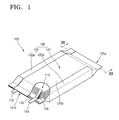
- FIG. 1 is a perspective view of a secondary battery 100 according to an embodiment of the invention.
- FIG. 2 is a development view of an exterior member 120 of FIG. 1 .
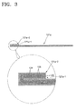
- FIG. 3 is a cross-sectional view taken along a line III-III' of FIG. 1 .
- the secondary battery 100 may include an electrode assembly 110 and an exterior member 120 sealing the electrode assembly 110.
- the electrode assembly 110 may include a positive electrode plate, a negative electrode plate, and a separator interposed therebetween.
- the positive electrode plate, the separator, and the negative electrode plate may be sequentially stacked to form the electrode assembly 110.
- the positive electrode plate may include a positive active material portion which is coated with a positive active material and a positive non-coated portion which is not coated with the positive active material.
- the positive active material portion is formed by coating, for example, a portion of at least one surface of an aluminum (Al) plate the positive active material, and the other portion of the surface of the aluminum plate which is not coated with the positive active material may be the positive non-coated portion.
- the positive active material may be a lithium-containing transition metal oxide such as lithium cobalt oxide (LiCoO 2 ), lithium nickel oxide (LiNiO 2 ), lithium manganese oxide (LiMnO 2 ), and lithium permanganate (LiMnO 4 ) or a lithium-chalcogenide compound.
- the negative electrode plate may include a negative active material portion which is coated with a negative active material and a negative non-coated portion which is not coated with the negative active material.
- the negative active material portion may be formed by coating, for example, a portion of at least one surface of a copper (Cu) plate with the negative active material. The other portion of the surface of the copper plate which is not coated with the negative active material may be the negative non-coated portion.
- the negative active material may be a carbon material such as crystalline carbon, amorphous carbon, a carbon composite, and carbon fiber, a lithium metal, or a lithium alloy.
- the separator may be manufactured by coating at least one material selected from the group consisting of polyethylene (PE), polystyrene (PS), polypropylene (PP), and a co-polymer including PE and PP with a polyvinylidene fluoride-hexafluoropropylene (PVDF-HFP) co-polymer, but is not limited thereto.
- PE polyethylene
- PS polystyrene
- PP polypropylene
- PVDF-HFP polyvinylidene fluoride-hexafluoropropylene
- a first electrode tab 112 and a second electrode tab 114 may be electrically connected to the electrode assembly 110.
- collectors 116 are respectively attached to the positive non-coated portion and the negative non-coated portion and may be connected to the first electrode tab 112 or the second electrode tab 114.
- the first electrode tab 112 and the second electrode tab 114 are exposed to the outside by penetrating a sealing unit 115 to which the exterior member 120 is attached.
- the electrode assembly 110 may be charged or discharged through the first electrode tab 112 and the second electrode tab 114.
- a shape of the exterior member 120 may vary.
- a single exterior member 120 may be formed, or a plurality of exterior members 120 maybe formed.
- a case where one exterior member 120 is formed will be described in detail for convenience of description.
- the exterior member 120 may include a pouch 121 which is flexible and a can 122 which is connected to the pouch 121 and is formed of a material having a greater hardness than that of the pouch 121.
- the pouch 121 may include first insulating layers 123, metal layers 124, and second insulating layers 125 which are sequentially stacked.
- the first insulating layers 123 and the second insulating layers 125 may be formed of PP, polyethyleneterephthalate (PET), nylon, etc.
- the metal layers 124 may be formed of Al, steel, stainless steel, etc.
- the pouch 121 may be variously formed.
- the pouch 121 may have a trilayer structure in which the first insulating layers 123 formed of PP, the metal layers 124 formed of Al, and the second insulating layers 125 formed of PET are stacked.
- the pouch 121 may include a first sealing portion 121 a, a pouch body 121b, and a second sealing portion 121c.
- the first sealing portion 121a, the pouch body 121b, and the second sealing portion 121c may include the first insulating layers 123, the metal layers 124, and the second insulating layers 125 which are described above.
- the can 122 may be formed of a material having a greater hardness than that of the pouch 121.
- the can 122 may be formed of a metal such as Al or an Al alloy.
- the pouch 121 and the can 122 may be connected to each other through a thermal bonding process. More specifically, the pouch 121 and the can 122 may be connected to each other through a usual thermal bonding process by applying heat ranging from about 1500 to about 2000°C for about 1 to 5 seconds at a pressure ranging from about 0.1 to about 0.5 MPa by using a well-known sealing apparatus.
- the pouch 121 and the can 122 may be connected to each other by using various methods.
- the pouch 121 is rectangular-shaped, and the can 122 may be inserted into the pouch 121.
- the pouch 121 may be connected to the can 122 through the thermal bonding process as described above.
- the pouch 121 may be formed as a shape 'I' (refer to FIG. 2A ) or '[' (refer to FIG. 2B ).
- the can 122 may be installed in a center portion of the pouch 21 or inside the pouch 121.
- the pouch 121 is not limited to the above and may have various shapes.
- a case where the pouch 121 is formed in the shape '[' will be described in detail for convenience of description.
- a plurality of cans 122 may be included in the exterior member 120, may be spaced apart from each other, and may be connected to each other by the pouch 121.
- a single pouch 121 or a plurality of pouches 121 may be formed.
- the cans 122 and the pouches 121 may be alternately arranged, and the pouches 121 may be respectively connected to the cans 122 in order to surround a part of an exterior surface of each of the cans 122.
- the pouches 121 may longer than the cans 122.
- the pouch 121 may include the first sealing portion 121 a, the pouch body 121b, and the second sealing portion 121c.
- the can 122 may include a first can 122a which is installed in a space formed by the first sealing portion 121 a, the pouch body 121b, and the second sealing portion 121c, and a second can 122b which is installed inside the pouch body 121 b.
- the pouch 121 and the can 122 are respectively formed and thermal-bonded to each other, and thus one exterior member 120 may be manufactured. Also, during the manufacture of the exterior member 120, the above-described electrode assembly 110 may be manufactured.
- the exterior member 120 is bent, and a space may be formed in the exterior member 120. More specifically, methods of bending the exterior member 120 may vary.
- the space may be formed by applying pressure to a part of the exterior member 120 such that the part may be bent.
- at least one of the first can 122a and the second can 122b may be arranged in a bent portion of the exterior member 120.
- the first can 122a may be arranged in the bent portion of the exterior member 120.
- the second can 122b may be arranged in the bent portion of the exterior member 120.
- the first can 122a and the second can 122b may be arranged in the bent portion of the exterior member 120.
- first can 122a and the second can 122b may face each other.
- first can 122a and the second can 122b are arranged to face each other in the bent portion of the exterior member 120 will be described in detail for convenience of description.
- the first can 122a and the second can 122b may be bent.
- the first can 122a may include first bending portions 122a-1 formed to be bent and a first can body portion 122a-2 connected to the first bending portions 122a-1 and forming a side surface of the secondary battery 100.
- a pair of first bending portions 122a-1 are formed and, in particular, may be arranged to face each other on both sides of the first can body portion 122a-2 with respect to the first can body portion 122a-2.
- the second can 122b may include second bending portions 122b-1 and a second can body portion 122b-2.
- a pair of second bending portions 122b-1 may exist and may be arranged to face each other on both sides of the second can body portion 122b-2 with respect to second can body portion 122b-2..
- each first bending portion 122a-1 and each second bending portion 122b-1 may be arranged on the same plane.
- the first can body portion 122a-2 and the second can body portion 122b-2 may be arranged to face each other.
- an overall shape of the exterior member 120 may be similar to a rectangular pillar.
- each portion of the pouch 121 and the can 122 are thermal-bonded, and thus an exterior surface of the exterior member 120 may have a closed-loop shape.
- both ends of the first sealing portion 121 a may be thermal-bonded.
- the pouch body 121b and the first can 122a may be thermal-bonded.
- Both ends of the second sealing portion 121 c may be thermal-bonded.
- the first sealing portion 121a may include a first bonding portion 121a-1 forming one end of the first sealing portion 121a and a second bonding portion 121 a-2 forming another end thereof.
- the first bonding portion 121 a-1 may protrude beyond an end of the first can 122a toward the outside.
- a width W1 of the first sealing portion 121a and a width W3 of the second sealing portion 121c may be different from a width W2 of the pouch body 121b.
- the width W1 of the first sealing portion 121a and the width W3 of the second sealing portion 121c may be larger than the width W2 of the pouch body 121 b. That is, the width W1 of the first sealing portion 121a and the width W3 of the second sealing portion 121c may be larger than the width W2 of the pouch body 121b, thereby sufficiently securing a length used to fold and bend the first sealing portion 121 a and the second sealing portion 121c when the pouch body 121 b is bonded to the first can 122a.
- the first bonding portion 121a-1 and the second bonding portion 121a-2 may be connected to each other through thermal bonding. More specifically, when the first bonding portion 121a-1 and the second bonding portion 121a-2 are thermal-bonded, one of the first bonding portion 121a-1 and the second bonding portion 121a-2 may be folded to overlap a same surface. For example, the first bonding portion 121 a-1 may be folded such that the first insulating layers 123 of the first bonding portion 121a-1 contact each other or the second insulating layers 125 of the first bonding portion 121a-1 contact each other.
- the second bonding portion 121a-2 may be folded such that the first insulating layers 123 of the second bonding portion 121a-2 contact each other or the second insulating layers 125 of the second bonding portion 121a-2 contact each other.
- the second insulating layers 125 of the first bonding portion 121 a-1 or the second insulating layers 125 of the second bonding portion 121a-2 may be arranged in a space in which the exterior member 120 is formed.
- the first insulating layers 123 of the first bonding portion 121a-1 or the first insulating layers 123 of the second bonding portion 121a-2 may be exposed to the outside the space in which the exterior member 120 is formed.
- first bonding portion 121 a-1 is folded such that the second insulating layers 125 of the first bonding portion 121a-1 contact each other will be described in detail for convenience of description.
- the second insulating layers 125 of the first bonding portion 121a-1 may contact each other.
- the first insulating layers 123 of the first bonding portion 121a-1 may be exposed to the outside.
- the second bonding portion 121a-2 is arranged to correspond to the first bonding portion 121a-1 and then thermal-bonded.
- the first insulating layers 123 of the first bonding portion 121a-1 that are exposed to the outside are arranged to correspond to the first insulating layers 123 of the second bonding portion 121a-2 and then thermal-bonded.
- the second insulating layers 125 of the first bonding portion 121a-1 may contact each other and may be thermal-bonded.
- the first insulating layers 123 of the first bonding portion 121a-1 and the first insulating layers 123 of the second bonding portion 121a-2 are thermal-bonded and bonded to each other by using same or similar materials, and thus not only the first bonding portion 121a-1 and the second bonding portion 121a-2 have a good bonding force, and a thermal expansion coefficient is the same, and thus but also a separation, etc. caused by thermal expansion on a bonded interface of the first bonding portion 121a-1 and the second bonding portion 121a-2 may be effectively prevented.
- the second insulating layers 125 of the first bonding portion 121a-1 are formed of the same material, a good bonding force may be secured when thermal bonding process is performed.
- portions of the first sealing portion 121a other than the first bonding portion 121a-1 and the second bonding portion 121a-2 may be bonded in a lengthwise direction.
- first bonding portion 121a-1 is bonded to the second bonding portion 121a-2
- first sealing portion 121 a is configured as a closed circuit
- surfaces of the first sealing portion 121 a facing each other in a lengthwise direction of the first sealing portion 121 a may be thermal-bonded to each other.
- the pouch body 121b and the first can 122a may be thermal-bonded to each other.
- a bonding method is the same or similar as described above, and thus a detailed description thereof will be omitted.
- the first sealing portion 121 a of the exterior member 120 may be sealed, and the second sealing portion 121c of the exterior member 120 may be open. Thereafter, the second sealing portion 121c is sealed after the electrode assembly 110 and an electrolyte (not shown) are inserted into the exterior member 120, thereby completely manufacturing the secondary battery 100.
- a method of sealing the second sealing portion 121c may be the same or similar as described above.
- the second sealing portion 121c may include a third bonding portion 121 c-1 and a fourth bonding portion 121c-2 that form both ends of the second sealing portion 121c.
- the third bonding portion 121c-1 and the fourth bonding portion 121c-2 are respectively the same or similar as the first bonding portion 121a-1 and the second bonding portion 121a-2 described above, and thus, detailed descriptions thereof will be omitted.
- the third bonding portion 121 c-1 and the fourth bonding portion 121c-2 may be thermal-bonded and connected to each other by folding one of the third bonding portion 121c-1 and the fourth bonding portion 121c-2.
- a method of connecting the third bonding portion 121 c-1 and the fourth bonding portion 121c-2 is the same or similar as the method of connecting the first bonding portion 121a-1 and the second bonding portion 121a-2 described above, and thus, a detailed description thereof will be omitted.
- the electrode assembly 110 and the electrolyte may be completely sealed by bonding the second sealing portion 121c is bonded in a lengthwise direction of the second sealing portion 121c,.
- the first electrode tab 112 and the second electrode tab 114 which are connected to the electrode assembly 110 may penetrate the second sealing portion 121c, and may be partially exposed to the outside.
- the secondary battery 100 may be variously formed.
- the secondary battery 100 may be formed by applying pressure to the secondary battery 100 disposed on a jig to have a curved surface of a predetermined radius of curvature or at least one radius of curvature.
- external pressure may be directly applied to the exterior member 120 or internal pressure of the exterior member 120 may be increased due to the external pressure.
- the can 122 may provide rigidity in order to endure a part of the external pressure or an increase of the internal pressure.
- the pouch 121 provides elasticity, thereby preventing damage which may occur when the secondary battery 100 is modified.
- FIG. 4 is a perspective view of a secondary battery 200 according to another embodiment.
- FIG. 5 is a development view of an exterior member 220 of FIG. 4 .
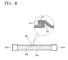
- FIG. 6 is a cross-sectional view taken along a line IV-IV' of FIG. 4 .
- the secondary battery 200 may include an electrode assembly 210 and the exterior member 220.
- the electrode assembly 210 may be substantially the same as the electrode assembly 110 described with reference to FIGS. 1 through 3 , and thus detailed descriptions of the electrode assembly 210 will be omitted.
- the exterior member 220 may include a can 222 and a pouch 221.
- the can 222 and the pouch 221 are substantially the same as the can 122 and the pouch 121, and thus detailed descriptions of the can 222 and the pouch 221 will be omitted.
- the number of pouch 221 may be one.
- the pouch 221 may have a rectangular shape.
- the pouch 221 may include a first sealing portion 221 a, a pouch body 221 b, and a second sealing portion 221 c.
- the first sealing portion 221 a includes a first bonding portion 221a-1 and a second bonding portion 221a-2
- the second sealing portion 221 c may include a third bonding portion 221 c-1 and a fourth bonding portion 221 c-2.
- a first can 222a and a second can 222b may be bent. If the electrode assembly 210 is inserted into the first can 222a and the second can 222b, the first can 222a and the second can 222b may be respectively arranged on sides of the electrode assembly 210.
- the first sealing portion 221 a and the second sealing portion 221 c may be thermal-bonded to each other.
- the first bonding portion 221a-1 of the first sealing portion 221a and the second bonding portion 221a-2 of the first sealing portion 221 a are bonded to each other, and the third bonding portion 221 c-1 of the second sealing portion 221 c and the fourth bonding portion 221 c-2 of the second sealing portion 221 c may be bonded to each other.
- both ends of the pouch body 221 b may be bonded to each other.
- a method of bonding each of the above-listed components may be a method of bonding the first sealing portion 221 a and the pouch body 221 b to first insulating layers 223 of the second sealing portion 221 c, or bonding the first sealing portion 221 a and the pouch body 221 b to second insulating layers 225 of the second sealing portion 221 c, as described with reference to FIGS. 1 through 3 .
- the first sealing portion 221 a is thermal-bonded and may seal a surface of the exterior member 220.
- a method of sealing the exterior member 220 is substantially the same as the above-described method, and thus a detailed description regarding the method will be omitted.
- the electrode assembly 210 is inserted into the second sealing portion 221 c which is open and then the electrolyte (not shown) is injected into the same. Then, the second sealing portion 221c is thermal-bonded. In this case, a first electrode tab 212 and a second electrode tab 214 penetrate the second sealing portion 221 c, and portions thereof may be exposed to the outside.
- the secondary battery 200 may be deformed by using a jig or the like. Pressure of which intensity is diverse or strength may be applied to the secondary battery 200.
- pressure of which intensity is diverse or strength may be applied to the secondary battery 200.
- the can 222 has rigidity in order to endure the pressure or strength applied to the secondary battery 200, and the pouch 221 may provide elasticity to the secondary battery 200 when the secondary battery 200 is deformed.
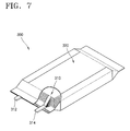
- FIG. 7 is a perspective view of a secondary battery 300 according to another embodiment.
- FIG. 8 is a development view of a first exterior member 320a and a second exterior 320b member of FIG. 7 .
- the secondary battery 300 may include an exterior member 320 and an electrode assembly 310.
- the electrode assembly 310 is substantially the same as the electrode assembly 110 described with reference to FIGS. 1 through 3 , and thus a detailed description regarding the electrode assembly 310 will be omitted.
- the exterior member 320 may include the first exterior member 320a and the second exterior member 320b which are connected to each other and seal the electrode assembly 310. At least one of the first exterior member 320a and the second exterior member 320b may include a pouch (not shown) which is flexible and a can (not shown) which is connected to the pouch and is formed of a material having a higher hardness than the pouch. For example, only the first exterior member 320a may include the pouch and the can. As another example, only the second exterior member 320b may include the pouch and the can. As another example, both the first exterior member 320a and the second exterior member 320b may include the pouch and the can.
- a case where the first exterior member 320a and the second exterior member 320b may include the pouch and the can will be described in detail for convenience.
- the pouch may include first insulating layers (not shown), metal layers (not shown), and second insulating layers (not shown).
- first insulating layers, the metal layers, and the second insulating layers are substantially the same as above, and thus detailed descriptions regarding the first insulating layers, the metal layers, and the second insulating layers will be omitted.
- the first exterior member 320a may include a first pouch 321 a and at least one can 322a.
- the number of can 322a may vary according to necessity, and hereinafter, a case where the can 322a includes a first can 322a-1 and a second can 322a-2 will be described in detail for convenience.
- the second exterior member 320b may include a second pouch 321 b or may include the second pouch 321 b and at least one can 322b.
- the number of the can 322b may vary according to necessity, which is substantially the same as the number of the first exterior member 320a.
- the second exterior member 320b includes the second pouch 321 b and the can 322b, and the can 322b of the second exterior member 320b will be referred to as a third can 322b for convenience.
- the first pouch 321 a and the second pouch 321 b may have various shapes.
- the first pouch 321 a may have substantially the same shape as the pouches 121 and 221 described with reference to FIGS. 1 through 6 .
- the second pouch 321 b may have substantially the same shape as the pouches 121 and 221 described with reference to FIGS. 1 through 6 .
- the first pouch 321 a is the same as the pouch 121 described with reference to FIGS. 1 through 3
- the second pouch 321 b has a rectangular shape which is similar to the shape of the pouch 221 described with reference to FIGS. 4 through 6 .
- the first pouch 321 a, the first can 322a-1, and the second can 322a-2 are variously arranged.
- the first pouch 321 a, the first can 322a-1, and the second can 322a-2 may be connected to each other, and the first can 322a-1 and the second can 322a-2 may be separated from each other.
- the first pouch 321 a may have various shapes such as a '[' shape, an 'I' shape, or a rectangular shape.
- a case where the first pouch 321 a has the rectangular shape will be described in detail for convenience.
- the second pouch 321 b and the third can 322b may also be variously arranged.
- the second pouch 321 b may have a rectangular shape, and the third can 322b may be inserted into a center of the second pouch 321 b.
- the second pouch 321 b it is possible for the second pouch 321 b to have a '[' shape and for the third can 322b to be arranged in an open area of the second pouch 321 b.
- a case where the second pouch 321 b may have the rectangular shape and the third can 322b is inserted into the center of the second pouch 321 b will be described in detail for convenience.
- the electrode assembly 310, the first exterior member 320a, and the second exterior member 320b may be manufactured first.
- a method of manufacturing the first exterior member 320a and the second exterior member 320b is substantially the same as the method described with reference to FIGS. 1 through 3 , and thus a detailed description regarding the manufacturing method of manufacturing the first exterior member 320a, and the second exterior member 320b will be omitted.
- the first exterior member 320a and the second exterior member 320b may be thermal-bonded to each other.
- both ends of the first pouch 321 a may be bonded to those of the second pouch 321 b.
- the first can 322a-1 and the second can 322a-2 may be curved, and a method of curving the first can 322a-1 and the second can 322a-2 is substantially the same as above.
- the method of bonding the ends of the first pouch 321 a to those of the second pouch 321 b may be substantially the same as the method of bonding the first bonding portion 121a-1 to the second bonding portion 121a-2.
- ends of one of the first pouch 321 a and the second pouch 321b are bent and contact ends of the other of the first pouch 321 a and the second pouch 321 b. Then, the ends of the first pouch 321 a and the second pouch 321 b are thermal-bonded to each other.
- a first sealing portion 321a-1 of the first pouch 321 a may be attached to the second pouch 321 b and then sealed.
- a second sealing portion 321-2 of the first pouch 321 a is open, and thus an open area of the exterior member 320 may be formed.
- the second sealing portion 321-2 of the first pouch 321a and the second pouch 321 b are thermal-bonded and then completely sealed.
- a first electrode tab 312 and a second electrode tab 314 may be exposed to the outside through a gap between the second sealing portion 321-2 and the second pouch 321 b.
- the first can 322a-1 and the second can 322a-2 may form a side of the secondary battery 300. Also, the third can 322b may form a center of the secondary battery 300.
- the first can 322a-1 through the third can 322b may endure external strength or external pressure which is applied when the secondary battery 300 is deformed.
- the third can 322b prevents the secondary battery 300 from restoring its shape after the deformation, and thus the shape of the secondary battery 300 may be maintained.
- elasticity or a restoring force with regard to internal pressure applied by at least one of the electrolyte (not shown) in the exterior member 320 and the electrode assembly 310 may be provided.
- a shape of a secondary battery may be easily changed and the secondary battery may have rigidity.
Landscapes
- Chemical & Material Sciences (AREA)
- Chemical Kinetics & Catalysis (AREA)
- Electrochemistry (AREA)
- General Chemical & Material Sciences (AREA)
- Inorganic Chemistry (AREA)
- Sealing Battery Cases Or Jackets (AREA)
Abstract
Description
- The invention relates to a secondary battery.
- Unlike a primary battery which cannot be recharged, a secondary battery, which can be repeatedly charged and discharged, is economical and environment-friendly, and thus, it is encouraged for use. Recently, types of electronic devices using the secondary battery have been diversified, and designs of the electronic devices become an important factor in determining the purchase of the electronic devices.
- For example, various wearable computer technologies which use the secondary battery as a power supply source and applications of the wearable computer technologies have been developed and released. Also, electronic devices such as mobile phones and laptop computers have predetermined curved surfaces for an ergonomic design.
- A shape of the secondary battery for operating the electronic devices needs to be changed in various ways, for example, bending, according to shapes of the electronic devices.
- The present invention sets out to provide a secondary battery that may easily change its shape.
- Additional aspects will be set forth in part in the description which follows and, in part, will be apparent from the description, or may be learned by practice of the presented embodiments.
- According to one or more embodiments of the invention, a secondary battery includes: an electrode assembly; and an exterior member which seals the electrode assembly. The exterior member includes: a pouch which is flexible; and a can which is connected to the pouch and is formed of a material having a greater hardness than that of the pouch.
- The pouch and the can may be thermal-bonded and connected to each other.
- The can may form at least one of side surfaces of the exterior member.
- The can may be bent to surround side surfaces of the electrode assembly.
- The can may be arranged in a center portion of the exterior member.
- The exterior member may be curved to have at least one radius of curvature.
- The pouch may include: a first sealing portion; a pouch body which is connected to the first sealing portion; and a second sealing portion which is arranged to face the first sealing portion and is connected to the pouch body.
- Each of the first sealing portion and the second sealing portion may be vertically connected to the pouch body.
- A width of the first sealing portion may be different from a width of the pouch body.
- The width of the first sealing portion may be greater than the width of the pouch body.
- The can may be inserted into the pouch body and may be connected to the first sealing portion, the second sealing portion, and the pouch body.
- The can may be arranged in a space formed by the first sealing portion, the second sealing portion, and the pouch body and may be connected to the first sealing portion, the second sealing portion, and the pouch body.
- At least one of an end of the first sealing portion and an end of the second sealing portion may protrude from an end of the can.
- A plurality of cans may be formed, and the plurality of cans may be spaced apart from each other and may be connected to the pouch body.
- According to one or more exemplary embodiments, a secondary battery includes: an electrode assembly; and an exterior member which includes a first exterior member and a second exterior member. The first exterior member and the second exterior member are connected to each other and seal the electrode assembly, and at least one of the first exterior member and the second exterior member includes: a pouch which is flexible; and a can which is connected to the pouch and is formed of a material having a greater hardness than the pouch.
- The at least one of the first exterior member and the second exterior member may be formed of a flexible material.
- The pouch and the can may be thermal-bonded and connected to each other.
- The can may form at least one side of the exterior member.
- The can may be arranged at a center of the exterior member.
- The exterior member may be curved due to curvature having at least one radius of curvature.
- At least some of the above and other features of the invention are set out in the claims.
- The above and/or other aspects of the invention will become apparent and more readily appreciated from the following description of embodiments of the invention, taken in conjunction with the accompanying drawings in which:
-
FIG. 1 is a perspective view of a secondary battery according to an embodiment of the invention; -
FIG. 2 is a development view of an exterior member ofFIG. 1 ; -
FIG. 3 is a cross-sectional view taken along a line III-III' ofFIG. 1 ; -
FIG. 4 is a perspective view of a secondary battery according to another embodiment of the invention; -
FIG. 5 is a development view of an exterior member ofFIG. 4 ; -
FIG. 6 is a cross-sectional view taken along a line IV-IV' ofFIG. 4 ; -
FIG. 7 is a perspective view of a secondary battery according to another embodiment of the invention; and -
FIG. 8 is a development view of a first exterior member and a second exterior member ofFIG. 7 . - The present invention will now be described more fully with reference to the accompanying drawings, in which embodiments of the invention are shown. The invention may, however, be embodied in many different forms and should not be construed as being limited to the embodiments set forth herein; rather, these embodiments are provided so that this disclosure will be thorough, and will convey the concept of the invention to those skilled in the art. In the drawings, the thicknesses of layers and regions are exaggerated for clarity. The terms used in the present specification are merely used to describe particular embodiments, and are not intended to limit the present invention. An expression used in the singular encompasses the expression of the plural, unless it has a clearly different meaning in the context. In the present specification, it is to be understood that the terms such as "including", "having", and "comprising" are intended to indicate the existence of the features, numbers, steps, actions, components, parts, or combinations thereof disclosed in the specification, and are not intended to preclude the possibility that one or more other features, numbers, steps, actions, components, parts, or combinations thereof may exist or may be added. While such terms as "first", "second", etc., may be used to describe various components, such components must not be limited to the above terms. The above terms are used only to distinguish one component from another.
-
FIG. 1 is a perspective view of asecondary battery 100 according to an embodiment of the invention.FIG. 2 is a development view of anexterior member 120 ofFIG. 1 .FIG. 3 is a cross-sectional view taken along a line III-III' ofFIG. 1 . - Referring to
FIGS. 1 through 3 , thesecondary battery 100 may include anelectrode assembly 110 and anexterior member 120 sealing theelectrode assembly 110. - The
electrode assembly 110 may include a positive electrode plate, a negative electrode plate, and a separator interposed therebetween. For example, the positive electrode plate, the separator, and the negative electrode plate may be sequentially stacked to form theelectrode assembly 110. - The positive electrode plate may include a positive active material portion which is coated with a positive active material and a positive non-coated portion which is not coated with the positive active material. The positive active material portion is formed by coating, for example, a portion of at least one surface of an aluminum (Al) plate the positive active material, and the other portion of the surface of the aluminum plate which is not coated with the positive active material may be the positive non-coated portion. The positive active material may be a lithium-containing transition metal oxide such as lithium cobalt oxide (LiCoO2), lithium nickel oxide (LiNiO2), lithium manganese oxide (LiMnO2), and lithium permanganate (LiMnO4) or a lithium-chalcogenide compound.
- The negative electrode plate may include a negative active material portion which is coated with a negative active material and a negative non-coated portion which is not coated with the negative active material. The negative active material portion may be formed by coating, for example, a portion of at least one surface of a copper (Cu) plate with the negative active material. The other portion of the surface of the copper plate which is not coated with the negative active material may be the negative non-coated portion. The negative active material may be a carbon material such as crystalline carbon, amorphous carbon, a carbon composite, and carbon fiber, a lithium metal, or a lithium alloy.
- The separator may be manufactured by coating at least one material selected from the group consisting of polyethylene (PE), polystyrene (PS), polypropylene (PP), and a co-polymer including PE and PP with a polyvinylidene fluoride-hexafluoropropylene (PVDF-HFP) co-polymer, but is not limited thereto.
- A
first electrode tab 112 and asecond electrode tab 114 may be electrically connected to theelectrode assembly 110. In particular,collectors 116 are respectively attached to the positive non-coated portion and the negative non-coated portion and may be connected to thefirst electrode tab 112 or thesecond electrode tab 114. Thefirst electrode tab 112 and thesecond electrode tab 114 are exposed to the outside by penetrating asealing unit 115 to which theexterior member 120 is attached. Theelectrode assembly 110 may be charged or discharged through thefirst electrode tab 112 and thesecond electrode tab 114. - A shape of the
exterior member 120 may vary. For example, asingle exterior member 120 may be formed, or a plurality ofexterior members 120 maybe formed. Hereinafter, however, a case where oneexterior member 120 is formed will be described in detail for convenience of description. - The
exterior member 120 may include apouch 121 which is flexible and a can 122 which is connected to thepouch 121 and is formed of a material having a greater hardness than that of thepouch 121. In this case, thepouch 121 may include first insulatinglayers 123,metal layers 124, and second insulatinglayers 125 which are sequentially stacked. In particular, the first insulatinglayers 123 and the second insulatinglayers 125 may be formed of PP, polyethyleneterephthalate (PET), nylon, etc., and the metal layers 124 may be formed of Al, steel, stainless steel, etc. Thepouch 121 may be variously formed. For example, thepouch 121 may have a trilayer structure in which the first insulatinglayers 123 formed of PP, the metal layers 124 formed of Al, and the second insulatinglayers 125 formed of PET are stacked. - The
pouch 121 may include afirst sealing portion 121 a, apouch body 121b, and asecond sealing portion 121c. In this case, thefirst sealing portion 121a, thepouch body 121b, and thesecond sealing portion 121c may include the first insulatinglayers 123, the metal layers 124, and the second insulatinglayers 125 which are described above. - As described above, the
can 122 may be formed of a material having a greater hardness than that of thepouch 121. For example, thecan 122 may be formed of a metal such as Al or an Al alloy. - The
pouch 121 and thecan 122 may be connected to each other through a thermal bonding process. More specifically, thepouch 121 and thecan 122 may be connected to each other through a usual thermal bonding process by applying heat ranging from about 1500 to about 2000°C for about 1 to 5 seconds at a pressure ranging from about 0.1 to about 0.5 MPa by using a well-known sealing apparatus. - The
pouch 121 and thecan 122 may be connected to each other by using various methods. For example, thepouch 121 is rectangular-shaped, and thecan 122 may be inserted into thepouch 121. In this case, as described above, thepouch 121 may be connected to thecan 122 through the thermal bonding process as described above. In addition, thepouch 121 may be formed as a shape 'I' (refer toFIG. 2A ) or '[' (refer toFIG. 2B ). In this case, thecan 122 may be installed in a center portion of the pouch 21 or inside thepouch 121. However, thepouch 121 is not limited to the above and may have various shapes. Hereinafter, a case where thepouch 121 is formed in the shape '[' will be described in detail for convenience of description. - Also, in that case, a plurality of
cans 122 may be included in theexterior member 120, may be spaced apart from each other, and may be connected to each other by thepouch 121. In this regard, asingle pouch 121 or a plurality ofpouches 121 may be formed. In particular, if the plurality ofpouches 121 are included in theexterior member 120, thecans 122 and thepouches 121 may be alternately arranged, and thepouches 121 may be respectively connected to thecans 122 in order to surround a part of an exterior surface of each of thecans 122. In this case, thepouches 121 may longer than thecans 122. - Hereinafter, a case where one
pouch 121 is included in theexterior member 120 and is formed in the shape '[' and twocans 122 are included in theexterior member 120 will be described in detail for convenience of description. - In more detail, as described above, the
pouch 121 may include thefirst sealing portion 121 a, thepouch body 121b, and thesecond sealing portion 121c. In this case, thecan 122 may include a first can 122a which is installed in a space formed by thefirst sealing portion 121 a, thepouch body 121b, and thesecond sealing portion 121c, and asecond can 122b which is installed inside thepouch body 121 b. - Upon reviewing a method of manufacturing the
secondary battery 100 by using theexterior member 120, thepouch 121 and thecan 122 are respectively formed and thermal-bonded to each other, and thus oneexterior member 120 may be manufactured. Also, during the manufacture of theexterior member 120, the above-describedelectrode assembly 110 may be manufactured. - When the above process is completed, the
exterior member 120 is bent, and a space may be formed in theexterior member 120. More specifically, methods of bending theexterior member 120 may vary. For example, the space may be formed by applying pressure to a part of theexterior member 120 such that the part may be bent. In this case, at least one of the first can 122a and thesecond can 122b may be arranged in a bent portion of theexterior member 120. For example, the first can 122a may be arranged in the bent portion of theexterior member 120. As another example, thesecond can 122b may be arranged in the bent portion of theexterior member 120. As another example, the first can 122a and thesecond can 122b may be arranged in the bent portion of theexterior member 120. In this case, the first can 122a and thesecond can 122b may face each other. Hereinafter, a case where the first can 122a and thesecond can 122b are arranged to face each other in the bent portion of theexterior member 120 will be described in detail for convenience of description. - As described above, if the
exterior member 120 is bent, the first can 122a and thesecond can 122b may be bent. In this case, the first can 122a may includefirst bending portions 122a-1 formed to be bent and a firstcan body portion 122a-2 connected to thefirst bending portions 122a-1 and forming a side surface of thesecondary battery 100. A pair offirst bending portions 122a-1 are formed and, in particular, may be arranged to face each other on both sides of the firstcan body portion 122a-2 with respect to the firstcan body portion 122a-2. - Like the first can 122a, the
second can 122b may includesecond bending portions 122b-1 and a secondcan body portion 122b-2. In this case, a pair ofsecond bending portions 122b-1 may exist and may be arranged to face each other on both sides of the secondcan body portion 122b-2 with respect to secondcan body portion 122b-2.. - As described above, if the first can 122a and the
second can 122b are bent, eachfirst bending portion 122a-1 and eachsecond bending portion 122b-1 may be arranged on the same plane. Also, the firstcan body portion 122a-2 and the secondcan body portion 122b-2 may be arranged to face each other. In this case, an overall shape of theexterior member 120 may be similar to a rectangular pillar. - After the above-described process is completed, each portion of the
pouch 121 and thecan 122 are thermal-bonded, and thus an exterior surface of theexterior member 120 may have a closed-loop shape. In this case, both ends of thefirst sealing portion 121 a may be thermal-bonded. Also, thepouch body 121b and the first can 122a may be thermal-bonded. Both ends of thesecond sealing portion 121 c may be thermal-bonded. - More specifically, the
first sealing portion 121a may include afirst bonding portion 121a-1 forming one end of thefirst sealing portion 121a and asecond bonding portion 121 a-2 forming another end thereof. In this case, thefirst bonding portion 121 a-1 may protrude beyond an end of the first can 122a toward the outside. - In this case, a width W1 of the
first sealing portion 121a and a width W3 of thesecond sealing portion 121c may be different from a width W2 of thepouch body 121b. For example, the width W1 of thefirst sealing portion 121a and the width W3 of thesecond sealing portion 121c may be larger than the width W2 of thepouch body 121 b. That is, the width W1 of thefirst sealing portion 121a and the width W3 of thesecond sealing portion 121c may be larger than the width W2 of thepouch body 121b, thereby sufficiently securing a length used to fold and bend thefirst sealing portion 121 a and thesecond sealing portion 121c when thepouch body 121 b is bonded to the first can 122a. - The
first bonding portion 121a-1 and thesecond bonding portion 121a-2 may be connected to each other through thermal bonding. More specifically, when thefirst bonding portion 121a-1 and thesecond bonding portion 121a-2 are thermal-bonded, one of thefirst bonding portion 121a-1 and thesecond bonding portion 121a-2 may be folded to overlap a same surface. For example, thefirst bonding portion 121 a-1 may be folded such that the first insulatinglayers 123 of thefirst bonding portion 121a-1 contact each other or the second insulatinglayers 125 of thefirst bonding portion 121a-1 contact each other. Also, thesecond bonding portion 121a-2 may be folded such that the first insulatinglayers 123 of thesecond bonding portion 121a-2 contact each other or the second insulatinglayers 125 of thesecond bonding portion 121a-2 contact each other. In this case, when one of thefirst bonding portion 121a-1 and thesecond bonding portion 121a-2 is folded to allow the first insulatinglayers 123 to contact each other, the second insulatinglayers 125 of thefirst bonding portion 121 a-1 or the second insulatinglayers 125 of thesecond bonding portion 121a-2 may be arranged in a space in which theexterior member 120 is formed. On the other hand, when one of thefirst bonding portion 121a-1 and thesecond bonding portion 121a-2 is folded to allow the second insulatinglayers 125 to contact each other, the first insulatinglayers 123 of thefirst bonding portion 121a-1 or the first insulatinglayers 123 of thesecond bonding portion 121a-2 may be exposed to the outside the space in which theexterior member 120 is formed. Hereinafter, a case where thefirst bonding portion 121 a-1 is folded such that the second insulatinglayers 125 of thefirst bonding portion 121a-1 contact each other will be described in detail for convenience of description. - When the
first bonding portion 121a-1 is folded, the second insulatinglayers 125 of thefirst bonding portion 121a-1 may contact each other. In this case, the first insulatinglayers 123 of thefirst bonding portion 121a-1 may be exposed to the outside. As described above, when thefirst bonding portion 121a-1 is folded, thesecond bonding portion 121a-2 is arranged to correspond to thefirst bonding portion 121a-1 and then thermal-bonded. In this case, the first insulatinglayers 123 of thefirst bonding portion 121a-1 that are exposed to the outside are arranged to correspond to the first insulatinglayers 123 of thesecond bonding portion 121a-2 and then thermal-bonded. The second insulatinglayers 125 of thefirst bonding portion 121a-1 may contact each other and may be thermal-bonded. In particular, in that case, the first insulatinglayers 123 of thefirst bonding portion 121a-1 and the first insulatinglayers 123 of thesecond bonding portion 121a-2 are thermal-bonded and bonded to each other by using same or similar materials, and thus not only thefirst bonding portion 121a-1 and thesecond bonding portion 121a-2 have a good bonding force, and a thermal expansion coefficient is the same, and thus but also a separation, etc. caused by thermal expansion on a bonded interface of thefirst bonding portion 121a-1 and thesecond bonding portion 121a-2 may be effectively prevented. Also, since the second insulatinglayers 125 of thefirst bonding portion 121a-1 are formed of the same material, a good bonding force may be secured when thermal bonding process is performed. - When the above process is being performed or is completely performed, portions of the
first sealing portion 121a other than thefirst bonding portion 121a-1 and thesecond bonding portion 121a-2 may be bonded in a lengthwise direction. In more detail, when thefirst bonding portion 121a-1 is bonded to thesecond bonding portion 121a-2, since thefirst sealing portion 121 a is configured as a closed circuit, surfaces of thefirst sealing portion 121 a facing each other in a lengthwise direction of thefirst sealing portion 121 amay be thermal-bonded to each other. - When the bonding of the
first sealing portion 121 a is performed, thepouch body 121b and the first can 122a may be thermal-bonded to each other. In this regard, a bonding method is the same or similar as described above, and thus a detailed description thereof will be omitted. - When the above process is completed, the
first sealing portion 121 a of theexterior member 120 may be sealed, and thesecond sealing portion 121c of theexterior member 120 may be open. Thereafter, thesecond sealing portion 121c is sealed after theelectrode assembly 110 and an electrolyte (not shown) are inserted into theexterior member 120, thereby completely manufacturing thesecondary battery 100. - In this case, a method of sealing the
second sealing portion 121c may be the same or similar as described above. For example, thesecond sealing portion 121c may include athird bonding portion 121 c-1 and afourth bonding portion 121c-2 that form both ends of thesecond sealing portion 121c. In this case, thethird bonding portion 121c-1 and thefourth bonding portion 121c-2 are respectively the same or similar as thefirst bonding portion 121a-1 and thesecond bonding portion 121a-2 described above, and thus, detailed descriptions thereof will be omitted. - The
third bonding portion 121 c-1 and thefourth bonding portion 121c-2 may be thermal-bonded and connected to each other by folding one of thethird bonding portion 121c-1 and thefourth bonding portion 121c-2. A method of connecting thethird bonding portion 121 c-1 and thefourth bonding portion 121c-2 is the same or similar as the method of connecting thefirst bonding portion 121a-1 and thesecond bonding portion 121a-2 described above, and thus, a detailed description thereof will be omitted. - When the
third bonding portion 121c-1 and thefourth bonding portion 121c-2 are completely bonded as described above, theelectrode assembly 110 and the electrolyte may be completely sealed by bonding thesecond sealing portion 121c is bonded in a lengthwise direction of thesecond sealing portion 121c,. In this case, thefirst electrode tab 112 and thesecond electrode tab 114 which are connected to theelectrode assembly 110 may penetrate thesecond sealing portion 121c, and may be partially exposed to the outside. - After the above process is completed, the
secondary battery 100 may be variously formed. For example, thesecondary battery 100 may be formed by applying pressure to thesecondary battery 100 disposed on a jig to have a curved surface of a predetermined radius of curvature or at least one radius of curvature. - When the above process is performed, external pressure may be directly applied to the
exterior member 120 or internal pressure of theexterior member 120 may be increased due to the external pressure. In this case, thecan 122 may provide rigidity in order to endure a part of the external pressure or an increase of the internal pressure. In addition, thepouch 121 provides elasticity, thereby preventing damage which may occur when thesecondary battery 100 is modified. - Therefore, damage of the
secondary battery 100 which may occur during a process of modifying thesecondary battery 100 in various forms may be prevented. Also, since thesecondary battery 100 may be modified by using small power, it is easy to manufacture thesecondary battery 100 in various forms. -
FIG. 4 is a perspective view of asecondary battery 200 according to another embodiment.FIG. 5 is a development view of anexterior member 220 ofFIG. 4 .FIG. 6 is a cross-sectional view taken along a line IV-IV' ofFIG. 4 . - Referring to
FIGS. 4 through 6 , thesecondary battery 200 may include anelectrode assembly 210 and theexterior member 220. In this case, theelectrode assembly 210 may be substantially the same as theelectrode assembly 110 described with reference toFIGS. 1 through 3 , and thus detailed descriptions of theelectrode assembly 210 will be omitted. - The
exterior member 220 may include acan 222 and apouch 221. In this case, thecan 222 and thepouch 221 are substantially the same as thecan 122 and thepouch 121, and thus detailed descriptions of thecan 222 and thepouch 221 will be omitted. - The number of
pouch 221 may be one. In this case, thepouch 221 may have a rectangular shape. Thepouch 221 may include afirst sealing portion 221 a, apouch body 221 b, and asecond sealing portion 221 c. Also, thefirst sealing portion 221 a includes afirst bonding portion 221a-1 and asecond bonding portion 221a-2, and thesecond sealing portion 221 c may include athird bonding portion 221 c-1 and afourth bonding portion 221 c-2. - When a method of manufacturing the
secondary battery 200 is examined, afirst can 222a and asecond can 222b may be bent. If theelectrode assembly 210 is inserted into the first can 222a and thesecond can 222b, the first can 222a and thesecond can 222b may be respectively arranged on sides of theelectrode assembly 210. - When the above process is completed, the
first sealing portion 221 a and thesecond sealing portion 221 c may be thermal-bonded to each other. Thefirst bonding portion 221a-1 of thefirst sealing portion 221a and thesecond bonding portion 221a-2 of thefirst sealing portion 221 a are bonded to each other, and thethird bonding portion 221 c-1 of thesecond sealing portion 221 c and thefourth bonding portion 221 c-2 of thesecond sealing portion 221 c may be bonded to each other. Also, both ends of thepouch body 221 b may be bonded to each other. A method of bonding each of the above-listed components may be a method of bonding thefirst sealing portion 221 a and thepouch body 221 b to first insulatinglayers 223 of thesecond sealing portion 221 c, or bonding thefirst sealing portion 221 a and thepouch body 221 b to second insulatinglayers 225 of thesecond sealing portion 221 c, as described with reference toFIGS. 1 through 3 . - When the above process is completed, the
first sealing portion 221 a is thermal-bonded and may seal a surface of theexterior member 220. In this case, a method of sealing theexterior member 220 is substantially the same as the above-described method, and thus a detailed description regarding the method will be omitted. - The
electrode assembly 210 is inserted into thesecond sealing portion 221 c which is open and then the electrolyte (not shown) is injected into the same. Then, thesecond sealing portion 221c is thermal-bonded. In this case, afirst electrode tab 212 and asecond electrode tab 214 penetrate thesecond sealing portion 221 c, and portions thereof may be exposed to the outside. - When the above process is completed, the
secondary battery 200 may be deformed by using a jig or the like. Pressure of which intensity is diverse or strength may be applied to thesecondary battery 200. In particular, if thesecondary battery 200 has a curved surface having curvature, pressure of which intensity is diverse or strength may be applied to thesecondary battery 200. In this regard, thecan 222 has rigidity in order to endure the pressure or strength applied to thesecondary battery 200, and thepouch 221 may provide elasticity to thesecondary battery 200 when thesecondary battery 200 is deformed. - Therefore, damage which may occur when the
secondary battery 200 is variously deformed may be prevented. Also, since thesecondary battery 200 may be deformed with low pressure, shapes of thesecondary battery 200 may vary. -
FIG. 7 is a perspective view of asecondary battery 300 according to another embodiment.FIG. 8 is a development view of afirst exterior member 320a and asecond exterior 320b member ofFIG. 7 . - Referring to
FIGS. 7 and8 , thesecondary battery 300 may include anexterior member 320 and anelectrode assembly 310. In this case, theelectrode assembly 310 is substantially the same as theelectrode assembly 110 described with reference toFIGS. 1 through 3 , and thus a detailed description regarding theelectrode assembly 310 will be omitted. - The
exterior member 320 may include thefirst exterior member 320a and thesecond exterior member 320b which are connected to each other and seal theelectrode assembly 310. At least one of thefirst exterior member 320a and thesecond exterior member 320b may include a pouch (not shown) which is flexible and a can (not shown) which is connected to the pouch and is formed of a material having a higher hardness than the pouch. For example, only thefirst exterior member 320a may include the pouch and the can. As another example, only thesecond exterior member 320b may include the pouch and the can. As another example, both thefirst exterior member 320a and thesecond exterior member 320b may include the pouch and the can. Hereinafter, however, a case where thefirst exterior member 320a and thesecond exterior member 320b may include the pouch and the can will be described in detail for convenience. - As described above, the pouch may include first insulating layers (not shown), metal layers (not shown), and second insulating layers (not shown). In this case, the first insulating layers, the metal layers, and the second insulating layers are substantially the same as above, and thus detailed descriptions regarding the first insulating layers, the metal layers, and the second insulating layers will be omitted.
- The
first exterior member 320a may include afirst pouch 321 a and at least one can 322a. The number of can 322a may vary according to necessity, and hereinafter, a case where thecan 322a includes a first can 322a-1 and a second can 322a-2 will be described in detail for convenience. - The
second exterior member 320b may include asecond pouch 321 b or may include thesecond pouch 321 b and at least one can 322b. The number of thecan 322b may vary according to necessity, which is substantially the same as the number of thefirst exterior member 320a. Hereinafter, thesecond exterior member 320b includes thesecond pouch 321 b and thecan 322b, and thecan 322b of thesecond exterior member 320b will be referred to as athird can 322b for convenience. - The
first pouch 321 a and thesecond pouch 321 b may have various shapes. For example, thefirst pouch 321 a may have substantially the same shape as thepouches FIGS. 1 through 6 . Also, thesecond pouch 321 b may have substantially the same shape as thepouches FIGS. 1 through 6 . Hereinafter, for convenience, thefirst pouch 321 a is the same as thepouch 121 described with reference toFIGS. 1 through 3 , and thesecond pouch 321 b has a rectangular shape which is similar to the shape of thepouch 221 described with reference toFIGS. 4 through 6 . - As shown in
FIGS. 7 and8 , thefirst pouch 321 a, the first can 322a-1, and the second can 322a-2 are variously arranged. In this case, thefirst pouch 321 a, the first can 322a-1, and the second can 322a-2 may be connected to each other, and the first can 322a-1 and the second can 322a-2 may be separated from each other. In particular, thefirst pouch 321 a may have various shapes such as a '[' shape, an 'I' shape, or a rectangular shape. Hereinafter, however, a case where thefirst pouch 321 a has the rectangular shape will be described in detail for convenience. - The
second pouch 321 b and thethird can 322b may also be variously arranged. For example, thesecond pouch 321 b may have a rectangular shape, and thethird can 322b may be inserted into a center of thesecond pouch 321 b. Also, it is possible for thesecond pouch 321 b to have a '[' shape and for thethird can 322b to be arranged in an open area of thesecond pouch 321 b. Hereinafter, a case where thesecond pouch 321 b may have the rectangular shape and thethird can 322b is inserted into the center of thesecond pouch 321 b will be described in detail for convenience. - When a method of manufacturing the
secondary battery 300 is examined, theelectrode assembly 310, thefirst exterior member 320a, and thesecond exterior member 320b may be manufactured first. In this case, a method of manufacturing thefirst exterior member 320a and thesecond exterior member 320b is substantially the same as the method described with reference toFIGS. 1 through 3 , and thus a detailed description regarding the manufacturing method of manufacturing thefirst exterior member 320a, and thesecond exterior member 320b will be omitted. - When the above process is completed, the
first exterior member 320a and thesecond exterior member 320b may be thermal-bonded to each other. In particular, both ends of thefirst pouch 321 a may be bonded to those of thesecond pouch 321 b. In this case, as shown inFIG. 7 , the first can 322a-1 and the second can 322a-2 may be curved, and a method of curving the first can 322a-1 and the second can 322a-2 is substantially the same as above. - As described above, when the ends of the
first pouch 321 a are respectively bonded to the ends of thesecond pouch 321 b, the method of bonding the ends of thefirst pouch 321 a to those of thesecond pouch 321 b may be substantially the same as the method of bonding thefirst bonding portion 121a-1 to thesecond bonding portion 121a-2. In particular, ends of one of thefirst pouch 321 a and thesecond pouch 321b are bent and contact ends of the other of thefirst pouch 321 a and thesecond pouch 321 b. Then, the ends of thefirst pouch 321 a and thesecond pouch 321 b are thermal-bonded to each other. - When the above process is completed, a
first sealing portion 321a-1 of thefirst pouch 321 a may be attached to thesecond pouch 321 b and then sealed. In this case, a second sealing portion 321-2 of thefirst pouch 321 a is open, and thus an open area of theexterior member 320 may be formed. - After the
electrode assembly 310 is inserted into the open area of theexterior member 320, the second sealing portion 321-2 of thefirst pouch 321a and thesecond pouch 321 b are thermal-bonded and then completely sealed. Afirst electrode tab 312 and asecond electrode tab 314 may be exposed to the outside through a gap between the second sealing portion 321-2 and thesecond pouch 321 b. - When the
secondary battery 300 is completed as described above, the first can 322a-1 and the second can 322a-2 may form a side of thesecondary battery 300. Also, thethird can 322b may form a center of thesecondary battery 300. - When the
secondary battery 300 is deformed due to external strength, the first can 322a-1 through thethird can 322b may endure external strength or external pressure which is applied when thesecondary battery 300 is deformed. In particular, when thesecondary battery 300 is curved, thethird can 322b prevents thesecondary battery 300 from restoring its shape after the deformation, and thus the shape of thesecondary battery 300 may be maintained. - As described above, when the external strength or external pressure is applied to the
first pouch 321 a and thesecond pouch 321 b, elasticity or a restoring force with regard to internal pressure applied by at least one of the electrolyte (not shown) in theexterior member 320 and theelectrode assembly 310 may be provided. - Therefore, damage which may occur when the
secondary battery 300 is variously deformed may be prevented. Also, since thesecondary battery 300 may be deformed with low pressure, shapes of thesecondary battery 300 may vary. - As described above, according to the one or more of the above embodiments, a shape of a secondary battery may be easily changed and the secondary battery may have rigidity.
- It should be understood that the embodiments described herein should be considered in a descriptive sense only and not for purposes of limitation. Descriptions of features or aspects within each embodiment should typically be considered as available for other similar features or aspects in other embodiments.
- While one or more embodiments of the invention have been described with reference to the figures, it will be understood by those of ordinary skill in the art that various changes in form and details may be made therein without departing from the scope of the invention as defined by the following claims.
Claims (16)
- A secondary battery comprising:an electrode assembly; andan exterior member which seals the electrode assembly,wherein the exterior member comprises:a pouch which is flexible; anda can which is connected to the pouch and is formed of a material having a greater hardness than that of the pouch.
- A secondary battery according to claim 1, wherein the pouch and the can are thermal-bonded and connected to each other.
- A secondary battery according to claim 1 or 2, wherein the can forms at least one of side surfaces of the exterior member.
- A secondary battery according to claim 3, wherein the can is bent to surround side surfaces of the electrode assembly.
- A secondary battery according to any preceding claim, wherein the can is arranged in a center portion of the exterior member.
- A secondary battery according to any preceding claim, wherein the exterior member is curved to have at least one radius of curvature.
- A secondary battery according to any preceding claim, wherein the pouch comprises:a first sealing portion;a pouch body which is connected to the first sealing portion; anda second sealing portion which is arranged to face the first sealing portion and is connected to the pouch body.
- A secondary battery according to claim 7, wherein each of the first sealing portion and the second sealing portion is vertically connected to the pouch body.
- A secondary battery according to claim 7 or 8, wherein a width of the first sealing portion is different from a width of the pouch body.
- A secondary battery according to claim 9, wherein the width of the first sealing portion is greater than the width of the pouch body.
- A secondary battery according to one of claims 7 to 10, wherein the can is inserted into the pouch body and is connected to the first sealing portion, the second sealing portion, and the pouch body.
- A secondary battery according to one of claims 7 to 11, wherein the can is arranged in a space formed by the first sealing portion, the second sealing portion, and the pouch body.
- A secondary battery according to claim 12, wherein at least one of an end of the first sealing portion and an end of the second sealing portion protrudes from an end of the can.
- A secondary battery according to one of claims 7 to 13, wherein a plurality of cans are formed, and
wherein the plurality of cans are spaced apart from each other and are connected to the pouch body. - A secondary battery according to any preceding claim:wherein the exterior member comprises a first exterior member and a second exterior member, wherein the first exterior member and the second exterior member are connected to each other and,at least one of the first exterior member and the second exterior member comprises the pouch which is flexible and the can.
- A secondary battery according to any preceding claim, wherein the exterior member comprises a flexible material.
Applications Claiming Priority (1)
| Application Number | Priority Date | Filing Date | Title |
|---|---|---|---|
| KR1020140123699A KR102233779B1 (en) | 2014-09-17 | 2014-09-17 | Secondary battery |
Publications (2)
| Publication Number | Publication Date |
|---|---|
| EP2999023A1 true EP2999023A1 (en) | 2016-03-23 |
| EP2999023B1 EP2999023B1 (en) | 2018-03-14 |
Family
ID=54148439
Family Applications (1)
| Application Number | Title | Priority Date | Filing Date |
|---|---|---|---|
| EP15185740.6A Active EP2999023B1 (en) | 2014-09-17 | 2015-09-17 | Secondary battery |
Country Status (4)
| Country | Link |
|---|---|
| US (1) | US10205136B2 (en) |
| EP (1) | EP2999023B1 (en) |
| KR (1) | KR102233779B1 (en) |
| CN (1) | CN105428561B (en) |
Cited By (2)
| Publication number | Priority date | Publication date | Assignee | Title |
|---|---|---|---|---|
| EP3428991A4 (en) * | 2016-04-15 | 2019-09-04 | Contemporary Amperex Technology Co., Limited | RECHARGEABLE BATTERY WITH FLEXIBLE PACKAGING |
| EP3588603A3 (en) * | 2018-06-05 | 2020-03-18 | SK Innovation Co., Ltd. | Pouch type secondary battery and method for manufacturing the same |
Families Citing this family (4)
| Publication number | Priority date | Publication date | Assignee | Title |
|---|---|---|---|---|
| KR102736483B1 (en) * | 2018-06-05 | 2024-11-29 | 에스케이온 주식회사 | Pouch type secondary battery and method for manufacturing the same |
| KR102840763B1 (en) * | 2020-06-04 | 2025-07-30 | 주식회사 엘지에너지솔루션 | High-energy density Pouch type secondary batter and manufacturing method of the same |
| KR102826600B1 (en) * | 2020-07-14 | 2025-06-27 | 에스케이온 주식회사 | Pouch case for secondary battery, Pouch type Secondary Battery, Secondary Battery Module and Manufacturing method of the secondary battery |
| US20240063477A1 (en) * | 2021-08-24 | 2024-02-22 | Lg Energy Solution, Ltd. | Secondary Battery, Method for Manufacturing the Same and Battery Pack |
Citations (4)
| Publication number | Priority date | Publication date | Assignee | Title |
|---|---|---|---|---|
| US20060263681A1 (en) * | 2005-04-27 | 2006-11-23 | Sang-Ho Lee | Secondary battery |
| US20080096105A1 (en) * | 2006-10-24 | 2008-04-24 | Samsung Sdi Co., Ltd. | Battery Pack |
| US20120009443A1 (en) * | 2010-07-09 | 2012-01-12 | Samsung Sdi Co., Ltd. | Battery Pack for a Lithium Polymer Battery |
| US20120015217A1 (en) * | 2005-03-25 | 2012-01-19 | Hyung Bok Lee | Polymer battery pack and method for manufacturing the same |
Family Cites Families (26)
| Publication number | Priority date | Publication date | Assignee | Title |
|---|---|---|---|---|
| JPH10162802A (en) * | 1996-11-29 | 1998-06-19 | Sony Corp | Separator, non-aqueous electrolyte battery and method of manufacturing the same |
| JP2002100326A (en) * | 2000-09-22 | 2002-04-05 | Gs-Melcotec Co Ltd | Flat battery |
| JP4821043B2 (en) * | 2000-11-08 | 2011-11-24 | Tdk株式会社 | Electrochemical devices |
| US7163762B2 (en) | 2000-11-21 | 2007-01-16 | Sony Corporation | Polymer electrolyte battery and method of producing same |
| JP4494713B2 (en) * | 2001-12-04 | 2010-06-30 | パナソニック株式会社 | Battery pack |
| US20030186122A1 (en) * | 2002-03-27 | 2003-10-02 | Ntk Powerdex, Inc. | Molded battery cup with protective/stiffening layer |
| KR100472504B1 (en) * | 2002-06-17 | 2005-03-10 | 삼성에스디아이 주식회사 | Pouch type secondary battery with improved reinforcement structure |
| KR100858798B1 (en) * | 2002-06-17 | 2008-09-17 | 삼성에스디아이 주식회사 | Battery and its manufacturing method |
| JP2005285557A (en) * | 2004-03-30 | 2005-10-13 | Sanyo Electric Co Ltd | Thin battery and manufacturing method thereof |
| KR100659845B1 (en) * | 2005-04-25 | 2006-12-19 | 삼성에스디아이 주식회사 | Pouch-type lithium secondary battery and method for manufacturing same |
| KR100933426B1 (en) | 2005-07-21 | 2009-12-23 | 주식회사 엘지화학 | Variable battery cartridge and medium-large battery module |
| KR100778982B1 (en) * | 2005-12-29 | 2007-11-22 | 삼성에스디아이 주식회사 | Pouch Case and Pouch Secondary Battery |
| KR100870354B1 (en) * | 2007-05-18 | 2008-11-25 | 삼성에스디아이 주식회사 | Battery exterior material and secondary battery using same |
| US8974952B2 (en) * | 2009-10-13 | 2015-03-10 | Samsung Sdi Co., Ltd. | Rechargeable battery |
| KR101097253B1 (en) * | 2009-11-19 | 2011-12-21 | 삼성에스디아이 주식회사 | Secondary battery |
| KR101040875B1 (en) * | 2009-12-31 | 2011-06-16 | 삼성에스디아이 주식회사 | Secondary battery |
| JP4803306B1 (en) * | 2010-04-07 | 2011-10-26 | ソニー株式会社 | Battery pack and battery pack manufacturing method |
| US20120219847A1 (en) * | 2011-02-24 | 2012-08-30 | Samsung Sdi Co., Ltd. | Pouch type battery and its manufacturing method |
| JP5510410B2 (en) * | 2011-08-02 | 2014-06-04 | 株式会社Gsユアサ | battery |
| US20130108907A1 (en) * | 2011-10-28 | 2013-05-02 | Apple Inc. | Curved battery cells for portable electronic devices |
| CN202721200U (en) * | 2012-04-19 | 2013-02-06 | 赵军辉 | Plastic-metal composite shell for lithium battery |
| KR101467630B1 (en) | 2012-05-22 | 2014-12-01 | 주식회사 엘지화학 | Can-pouch combined type secondary battery |
| JP5993633B2 (en) * | 2012-06-29 | 2016-09-14 | 日立マクセル株式会社 | Laminated battery |
| JP5278582B1 (en) * | 2012-07-23 | 2013-09-04 | 大日本印刷株式会社 | Magnesium ion secondary battery |
| KR20140064168A (en) * | 2012-11-19 | 2014-05-28 | 삼성에스디아이 주식회사 | Rechargeable lithium battery |
| JP2014120339A (en) * | 2012-12-17 | 2014-06-30 | Showa Denko Packaging Co Ltd | Sheath material for air secondary battery, manufacturing method of sheath material for air secondary battery and air secondary battery |
-
2014
- 2014-09-17 KR KR1020140123699A patent/KR102233779B1/en active Active
-
2015
- 2015-09-09 US US14/848,953 patent/US10205136B2/en active Active
- 2015-09-17 CN CN201510594212.1A patent/CN105428561B/en active Active
- 2015-09-17 EP EP15185740.6A patent/EP2999023B1/en active Active
Patent Citations (4)
| Publication number | Priority date | Publication date | Assignee | Title |
|---|---|---|---|---|
| US20120015217A1 (en) * | 2005-03-25 | 2012-01-19 | Hyung Bok Lee | Polymer battery pack and method for manufacturing the same |
| US20060263681A1 (en) * | 2005-04-27 | 2006-11-23 | Sang-Ho Lee | Secondary battery |
| US20080096105A1 (en) * | 2006-10-24 | 2008-04-24 | Samsung Sdi Co., Ltd. | Battery Pack |
| US20120009443A1 (en) * | 2010-07-09 | 2012-01-12 | Samsung Sdi Co., Ltd. | Battery Pack for a Lithium Polymer Battery |
Cited By (4)
| Publication number | Priority date | Publication date | Assignee | Title |
|---|---|---|---|---|
| EP3428991A4 (en) * | 2016-04-15 | 2019-09-04 | Contemporary Amperex Technology Co., Limited | RECHARGEABLE BATTERY WITH FLEXIBLE PACKAGING |
| US10673027B2 (en) | 2016-04-15 | 2020-06-02 | Contemporary Amperex Technology Co., Limited | Pouch-type secondary battery |
| EP3588603A3 (en) * | 2018-06-05 | 2020-03-18 | SK Innovation Co., Ltd. | Pouch type secondary battery and method for manufacturing the same |
| US11581602B2 (en) | 2018-06-05 | 2023-02-14 | Sk On Co., Ltd. | Pouch type secondary battery and method for manufacturing the same |
Also Published As
| Publication number | Publication date |
|---|---|
| EP2999023B1 (en) | 2018-03-14 |
| CN105428561A (en) | 2016-03-23 |
| KR102233779B1 (en) | 2021-03-30 |
| CN105428561B (en) | 2020-12-04 |
| US10205136B2 (en) | 2019-02-12 |
| US20160079575A1 (en) | 2016-03-17 |
| KR20160032929A (en) | 2016-03-25 |
Similar Documents
| Publication | Publication Date | Title |
|---|---|---|
| EP2999023B1 (en) | Secondary battery | |
| US9954204B2 (en) | Curved secondary battery | |
| JP6659092B2 (en) | Flexible secondary battery | |
| KR102152887B1 (en) | Flexible secondary battery | |
| EP2896086B1 (en) | Flexible secondary battery | |
| JP6635687B2 (en) | Curved secondary battery and method of manufacturing the same | |
| JP7004264B2 (en) | Flexible secondary battery | |
| KR102222112B1 (en) | Flexible secondary battery | |
| KR102221804B1 (en) | Flexible secondary battery | |
| US10319959B2 (en) | Flexible secondary battery | |
| CN104821411B (en) | Curved secondary battery and method of manufacturing the same | |
| CN104681849B (en) | The method of manufacture bending secondary cell | |
| EP2535961A1 (en) | Pouch type secondary battery and method for manufacturing the same | |
| KR20150086730A (en) | Flexible secondary battery | |
| KR20160008362A (en) | Flexible secondary battery | |
| US20160079574A1 (en) | Electrode assembly and secondary battery including the same | |
| CN105374956B (en) | Secondary battery | |
| US10854856B2 (en) | Curved secondary battery | |
| JP2022050682A (en) | Lithium secondary battery | |
| KR102103899B1 (en) | Secondary battery and manufactury methode for the same |
Legal Events
| Date | Code | Title | Description |
|---|---|---|---|
| PUAI | Public reference made under article 153(3) epc to a published international application that has entered the european phase |
Free format text: ORIGINAL CODE: 0009012 |
|
| AK | Designated contracting states |
Kind code of ref document: A1 Designated state(s): AL AT BE BG CH CY CZ DE DK EE ES FI FR GB GR HR HU IE IS IT LI LT LU LV MC MK MT NL NO PL PT RO RS SE SI SK SM TR |
|
| AX | Request for extension of the european patent |
Extension state: BA ME |
|
| 17P | Request for examination filed |
Effective date: 20160923 |
|
| RBV | Designated contracting states (corrected) |
Designated state(s): AL AT BE BG CH CY CZ DE DK EE ES FI FR GB GR HR HU IE IS IT LI LT LU LV MC MK MT NL NO PL PT RO RS SE SI SK SM TR |
|
| RIC1 | Information provided on ipc code assigned before grant |
Ipc: H01M 2/02 20060101AFI20170728BHEP Ipc: H01M 2/08 20060101ALI20170728BHEP |
|
| GRAP | Despatch of communication of intention to grant a patent |
Free format text: ORIGINAL CODE: EPIDOSNIGR1 |
|
| INTG | Intention to grant announced |
Effective date: 20170919 |
|
| GRAS | Grant fee paid |
Free format text: ORIGINAL CODE: EPIDOSNIGR3 |
|
| GRAA | (expected) grant |
Free format text: ORIGINAL CODE: 0009210 |
|
| AK | Designated contracting states |
Kind code of ref document: B1 Designated state(s): AL AT BE BG CH CY CZ DE DK EE ES FI FR GB GR HR HU IE IS IT LI LT LU LV MC MK MT NL NO PL PT RO RS SE SI SK SM TR |
|
| REG | Reference to a national code |
Ref country code: GB Ref legal event code: FG4D |
|
| REG | Reference to a national code |
Ref country code: CH Ref legal event code: EP Ref country code: AT Ref legal event code: REF Ref document number: 979664 Country of ref document: AT Kind code of ref document: T Effective date: 20180315 |
|
| REG | Reference to a national code |
Ref country code: IE Ref legal event code: FG4D |
|
| REG | Reference to a national code |
Ref country code: DE Ref legal event code: R096 Ref document number: 602015008694 Country of ref document: DE |
|
| REG | Reference to a national code |
Ref country code: NL Ref legal event code: MP Effective date: 20180314 |
|
| REG | Reference to a national code |
Ref country code: LT Ref legal event code: MG4D |
|
| PG25 | Lapsed in a contracting state [announced via postgrant information from national office to epo] |
Ref country code: LT Free format text: LAPSE BECAUSE OF FAILURE TO SUBMIT A TRANSLATION OF THE DESCRIPTION OR TO PAY THE FEE WITHIN THE PRESCRIBED TIME-LIMIT Effective date: 20180314 Ref country code: HR Free format text: LAPSE BECAUSE OF FAILURE TO SUBMIT A TRANSLATION OF THE DESCRIPTION OR TO PAY THE FEE WITHIN THE PRESCRIBED TIME-LIMIT Effective date: 20180314 Ref country code: NO Free format text: LAPSE BECAUSE OF FAILURE TO SUBMIT A TRANSLATION OF THE DESCRIPTION OR TO PAY THE FEE WITHIN THE PRESCRIBED TIME-LIMIT Effective date: 20180614 Ref country code: CY Free format text: LAPSE BECAUSE OF FAILURE TO SUBMIT A TRANSLATION OF THE DESCRIPTION OR TO PAY THE FEE WITHIN THE PRESCRIBED TIME-LIMIT Effective date: 20180314 Ref country code: FI Free format text: LAPSE BECAUSE OF FAILURE TO SUBMIT A TRANSLATION OF THE DESCRIPTION OR TO PAY THE FEE WITHIN THE PRESCRIBED TIME-LIMIT Effective date: 20180314 |
|
| REG | Reference to a national code |
Ref country code: AT Ref legal event code: MK05 Ref document number: 979664 Country of ref document: AT Kind code of ref document: T Effective date: 20180314 |
|
| REG | Reference to a national code |
Ref country code: FR Ref legal event code: PLFP Year of fee payment: 4 |
|
| PG25 | Lapsed in a contracting state [announced via postgrant information from national office to epo] |
Ref country code: GR Free format text: LAPSE BECAUSE OF FAILURE TO SUBMIT A TRANSLATION OF THE DESCRIPTION OR TO PAY THE FEE WITHIN THE PRESCRIBED TIME-LIMIT Effective date: 20180615 Ref country code: BG Free format text: LAPSE BECAUSE OF FAILURE TO SUBMIT A TRANSLATION OF THE DESCRIPTION OR TO PAY THE FEE WITHIN THE PRESCRIBED TIME-LIMIT Effective date: 20180614 Ref country code: LV Free format text: LAPSE BECAUSE OF FAILURE TO SUBMIT A TRANSLATION OF THE DESCRIPTION OR TO PAY THE FEE WITHIN THE PRESCRIBED TIME-LIMIT Effective date: 20180314 Ref country code: SE Free format text: LAPSE BECAUSE OF FAILURE TO SUBMIT A TRANSLATION OF THE DESCRIPTION OR TO PAY THE FEE WITHIN THE PRESCRIBED TIME-LIMIT Effective date: 20180314 Ref country code: RS Free format text: LAPSE BECAUSE OF FAILURE TO SUBMIT A TRANSLATION OF THE DESCRIPTION OR TO PAY THE FEE WITHIN THE PRESCRIBED TIME-LIMIT Effective date: 20180314 |
|
| PG25 | Lapsed in a contracting state [announced via postgrant information from national office to epo] |
Ref country code: RO Free format text: LAPSE BECAUSE OF FAILURE TO SUBMIT A TRANSLATION OF THE DESCRIPTION OR TO PAY THE FEE WITHIN THE PRESCRIBED TIME-LIMIT Effective date: 20180314 Ref country code: IT Free format text: LAPSE BECAUSE OF FAILURE TO SUBMIT A TRANSLATION OF THE DESCRIPTION OR TO PAY THE FEE WITHIN THE PRESCRIBED TIME-LIMIT Effective date: 20180314 Ref country code: AL Free format text: LAPSE BECAUSE OF FAILURE TO SUBMIT A TRANSLATION OF THE DESCRIPTION OR TO PAY THE FEE WITHIN THE PRESCRIBED TIME-LIMIT Effective date: 20180314 Ref country code: PL Free format text: LAPSE BECAUSE OF FAILURE TO SUBMIT A TRANSLATION OF THE DESCRIPTION OR TO PAY THE FEE WITHIN THE PRESCRIBED TIME-LIMIT Effective date: 20180314 Ref country code: NL Free format text: LAPSE BECAUSE OF FAILURE TO SUBMIT A TRANSLATION OF THE DESCRIPTION OR TO PAY THE FEE WITHIN THE PRESCRIBED TIME-LIMIT Effective date: 20180314 Ref country code: ES Free format text: LAPSE BECAUSE OF FAILURE TO SUBMIT A TRANSLATION OF THE DESCRIPTION OR TO PAY THE FEE WITHIN THE PRESCRIBED TIME-LIMIT Effective date: 20180314 Ref country code: EE Free format text: LAPSE BECAUSE OF FAILURE TO SUBMIT A TRANSLATION OF THE DESCRIPTION OR TO PAY THE FEE WITHIN THE PRESCRIBED TIME-LIMIT Effective date: 20180314 |
|
| PG25 | Lapsed in a contracting state [announced via postgrant information from national office to epo] |
Ref country code: AT Free format text: LAPSE BECAUSE OF FAILURE TO SUBMIT A TRANSLATION OF THE DESCRIPTION OR TO PAY THE FEE WITHIN THE PRESCRIBED TIME-LIMIT Effective date: 20180314 Ref country code: SM Free format text: LAPSE BECAUSE OF FAILURE TO SUBMIT A TRANSLATION OF THE DESCRIPTION OR TO PAY THE FEE WITHIN THE PRESCRIBED TIME-LIMIT Effective date: 20180314 Ref country code: CZ Free format text: LAPSE BECAUSE OF FAILURE TO SUBMIT A TRANSLATION OF THE DESCRIPTION OR TO PAY THE FEE WITHIN THE PRESCRIBED TIME-LIMIT Effective date: 20180314 Ref country code: SK Free format text: LAPSE BECAUSE OF FAILURE TO SUBMIT A TRANSLATION OF THE DESCRIPTION OR TO PAY THE FEE WITHIN THE PRESCRIBED TIME-LIMIT Effective date: 20180314 |
|
| REG | Reference to a national code |
Ref country code: DE Ref legal event code: R097 Ref document number: 602015008694 Country of ref document: DE |
|
| PG25 | Lapsed in a contracting state [announced via postgrant information from national office to epo] |
Ref country code: PT Free format text: LAPSE BECAUSE OF FAILURE TO SUBMIT A TRANSLATION OF THE DESCRIPTION OR TO PAY THE FEE WITHIN THE PRESCRIBED TIME-LIMIT Effective date: 20180716 |
|
| PLBE | No opposition filed within time limit |
Free format text: ORIGINAL CODE: 0009261 |
|
| STAA | Information on the status of an ep patent application or granted ep patent |
Free format text: STATUS: NO OPPOSITION FILED WITHIN TIME LIMIT |
|
| PG25 | Lapsed in a contracting state [announced via postgrant information from national office to epo] |
Ref country code: DK Free format text: LAPSE BECAUSE OF FAILURE TO SUBMIT A TRANSLATION OF THE DESCRIPTION OR TO PAY THE FEE WITHIN THE PRESCRIBED TIME-LIMIT Effective date: 20180314 |
|
| 26N | No opposition filed |
Effective date: 20181217 |
|
| PG25 | Lapsed in a contracting state [announced via postgrant information from national office to epo] |
Ref country code: SI Free format text: LAPSE BECAUSE OF FAILURE TO SUBMIT A TRANSLATION OF THE DESCRIPTION OR TO PAY THE FEE WITHIN THE PRESCRIBED TIME-LIMIT Effective date: 20180314 |
|
| PG25 | Lapsed in a contracting state [announced via postgrant information from national office to epo] |
Ref country code: MC Free format text: LAPSE BECAUSE OF FAILURE TO SUBMIT A TRANSLATION OF THE DESCRIPTION OR TO PAY THE FEE WITHIN THE PRESCRIBED TIME-LIMIT Effective date: 20180314 |
|
| REG | Reference to a national code |
Ref country code: CH Ref legal event code: PL |
|
| REG | Reference to a national code |
Ref country code: BE Ref legal event code: MM Effective date: 20180930 |
|
| REG | Reference to a national code |
Ref country code: IE Ref legal event code: MM4A |
|
| PG25 | Lapsed in a contracting state [announced via postgrant information from national office to epo] |
Ref country code: LU Free format text: LAPSE BECAUSE OF NON-PAYMENT OF DUE FEES Effective date: 20180917 |
|
| PG25 | Lapsed in a contracting state [announced via postgrant information from national office to epo] |
Ref country code: IE Free format text: LAPSE BECAUSE OF NON-PAYMENT OF DUE FEES Effective date: 20180917 |
|
| PG25 | Lapsed in a contracting state [announced via postgrant information from national office to epo] |
Ref country code: LI Free format text: LAPSE BECAUSE OF NON-PAYMENT OF DUE FEES Effective date: 20180930 Ref country code: BE Free format text: LAPSE BECAUSE OF NON-PAYMENT OF DUE FEES Effective date: 20180930 Ref country code: CH Free format text: LAPSE BECAUSE OF NON-PAYMENT OF DUE FEES Effective date: 20180930 |
|
| PG25 | Lapsed in a contracting state [announced via postgrant information from national office to epo] |
Ref country code: MT Free format text: LAPSE BECAUSE OF NON-PAYMENT OF DUE FEES Effective date: 20180917 |
|
| PG25 | Lapsed in a contracting state [announced via postgrant information from national office to epo] |
Ref country code: TR Free format text: LAPSE BECAUSE OF FAILURE TO SUBMIT A TRANSLATION OF THE DESCRIPTION OR TO PAY THE FEE WITHIN THE PRESCRIBED TIME-LIMIT Effective date: 20180314 |
|
| PG25 | Lapsed in a contracting state [announced via postgrant information from national office to epo] |
Ref country code: MK Free format text: LAPSE BECAUSE OF NON-PAYMENT OF DUE FEES Effective date: 20180314 Ref country code: HU Free format text: LAPSE BECAUSE OF FAILURE TO SUBMIT A TRANSLATION OF THE DESCRIPTION OR TO PAY THE FEE WITHIN THE PRESCRIBED TIME-LIMIT; INVALID AB INITIO Effective date: 20150917 |
|
| PG25 | Lapsed in a contracting state [announced via postgrant information from national office to epo] |
Ref country code: IS Free format text: LAPSE BECAUSE OF FAILURE TO SUBMIT A TRANSLATION OF THE DESCRIPTION OR TO PAY THE FEE WITHIN THE PRESCRIBED TIME-LIMIT Effective date: 20180714 |
|
| REG | Reference to a national code |
Ref country code: DE Ref legal event code: R079 Ref document number: 602015008694 Country of ref document: DE Free format text: PREVIOUS MAIN CLASS: H01M0002020000 Ipc: H01M0050100000 |
|
| P01 | Opt-out of the competence of the unified patent court (upc) registered |
Effective date: 20230528 |
|
| PGFP | Annual fee paid to national office [announced via postgrant information from national office to epo] |
Ref country code: DE Payment date: 20250902 Year of fee payment: 11 |
|
| PGFP | Annual fee paid to national office [announced via postgrant information from national office to epo] |
Ref country code: GB Payment date: 20250904 Year of fee payment: 11 |
|
| PGFP | Annual fee paid to national office [announced via postgrant information from national office to epo] |
Ref country code: FR Payment date: 20250908 Year of fee payment: 11 |