EP2998585A1 - Scroll compressor - Google Patents
Scroll compressor Download PDFInfo
- Publication number
- EP2998585A1 EP2998585A1 EP14830230.0A EP14830230A EP2998585A1 EP 2998585 A1 EP2998585 A1 EP 2998585A1 EP 14830230 A EP14830230 A EP 14830230A EP 2998585 A1 EP2998585 A1 EP 2998585A1
- Authority
- EP
- European Patent Office
- Prior art keywords
- wrap
- inner circumferential
- outer circumferential
- tip seal
- end plate
- Prior art date
- Legal status (The legal status is an assumption and is not a legal conclusion. Google has not performed a legal analysis and makes no representation as to the accuracy of the status listed.)
- Granted
Links
Images




Classifications
-
- F—MECHANICAL ENGINEERING; LIGHTING; HEATING; WEAPONS; BLASTING
- F04—POSITIVE - DISPLACEMENT MACHINES FOR LIQUIDS; PUMPS FOR LIQUIDS OR ELASTIC FLUIDS
- F04C—ROTARY-PISTON, OR OSCILLATING-PISTON, POSITIVE-DISPLACEMENT MACHINES FOR LIQUIDS; ROTARY-PISTON, OR OSCILLATING-PISTON, POSITIVE-DISPLACEMENT PUMPS
- F04C18/00—Rotary-piston pumps specially adapted for elastic fluids
- F04C18/02—Rotary-piston pumps specially adapted for elastic fluids of arcuate-engagement type, i.e. with circular translatory movement of co-operating members, each member having the same number of teeth or tooth-equivalents
- F04C18/0207—Rotary-piston pumps specially adapted for elastic fluids of arcuate-engagement type, i.e. with circular translatory movement of co-operating members, each member having the same number of teeth or tooth-equivalents both members having co-operating elements in spiral form
- F04C18/0215—Rotary-piston pumps specially adapted for elastic fluids of arcuate-engagement type, i.e. with circular translatory movement of co-operating members, each member having the same number of teeth or tooth-equivalents both members having co-operating elements in spiral form where only one member is moving
-
- F—MECHANICAL ENGINEERING; LIGHTING; HEATING; WEAPONS; BLASTING
- F01—MACHINES OR ENGINES IN GENERAL; ENGINE PLANTS IN GENERAL; STEAM ENGINES
- F01C—ROTARY-PISTON OR OSCILLATING-PISTON MACHINES OR ENGINES
- F01C19/00—Sealing arrangements in rotary-piston machines or engines
- F01C19/005—Structure and composition of sealing elements such as sealing strips, sealing rings and the like; Coating of these elements
-
- F—MECHANICAL ENGINEERING; LIGHTING; HEATING; WEAPONS; BLASTING
- F04—POSITIVE - DISPLACEMENT MACHINES FOR LIQUIDS; PUMPS FOR LIQUIDS OR ELASTIC FLUIDS
- F04C—ROTARY-PISTON, OR OSCILLATING-PISTON, POSITIVE-DISPLACEMENT MACHINES FOR LIQUIDS; ROTARY-PISTON, OR OSCILLATING-PISTON, POSITIVE-DISPLACEMENT PUMPS
- F04C18/00—Rotary-piston pumps specially adapted for elastic fluids
- F04C18/02—Rotary-piston pumps specially adapted for elastic fluids of arcuate-engagement type, i.e. with circular translatory movement of co-operating members, each member having the same number of teeth or tooth-equivalents
- F04C18/0207—Rotary-piston pumps specially adapted for elastic fluids of arcuate-engagement type, i.e. with circular translatory movement of co-operating members, each member having the same number of teeth or tooth-equivalents both members having co-operating elements in spiral form
- F04C18/0246—Details concerning the involute wraps or their base, e.g. geometry
- F04C18/0269—Details concerning the involute wraps
- F04C18/0276—Different wall heights
-
- F—MECHANICAL ENGINEERING; LIGHTING; HEATING; WEAPONS; BLASTING
- F04—POSITIVE - DISPLACEMENT MACHINES FOR LIQUIDS; PUMPS FOR LIQUIDS OR ELASTIC FLUIDS
- F04C—ROTARY-PISTON, OR OSCILLATING-PISTON, POSITIVE-DISPLACEMENT MACHINES FOR LIQUIDS; ROTARY-PISTON, OR OSCILLATING-PISTON, POSITIVE-DISPLACEMENT PUMPS
- F04C18/00—Rotary-piston pumps specially adapted for elastic fluids
- F04C18/02—Rotary-piston pumps specially adapted for elastic fluids of arcuate-engagement type, i.e. with circular translatory movement of co-operating members, each member having the same number of teeth or tooth-equivalents
- F04C18/0207—Rotary-piston pumps specially adapted for elastic fluids of arcuate-engagement type, i.e. with circular translatory movement of co-operating members, each member having the same number of teeth or tooth-equivalents both members having co-operating elements in spiral form
- F04C18/0246—Details concerning the involute wraps or their base, e.g. geometry
- F04C18/0269—Details concerning the involute wraps
- F04C18/0284—Details of the wrap tips
-
- F—MECHANICAL ENGINEERING; LIGHTING; HEATING; WEAPONS; BLASTING
- F04—POSITIVE - DISPLACEMENT MACHINES FOR LIQUIDS; PUMPS FOR LIQUIDS OR ELASTIC FLUIDS
- F04C—ROTARY-PISTON, OR OSCILLATING-PISTON, POSITIVE-DISPLACEMENT MACHINES FOR LIQUIDS; ROTARY-PISTON, OR OSCILLATING-PISTON, POSITIVE-DISPLACEMENT PUMPS
- F04C27/00—Sealing arrangements in rotary-piston pumps specially adapted for elastic fluids
- F04C27/005—Axial sealings for working fluid
Definitions
- the present invention relates to a scroll compressor.
- a scroll compressor is equipped with a fixed scroll and an orbiting scroll.
- Each of the fixed scroll and the orbiting scroll is a disk-shaped end plate provided with a spiral wrap on one surface side.
- Such a fixed scroll and an orbiting scroll are arranged to face each other with their wraps intermeshed, and the orbiting scroll is caused to revolve with respect to the fixed scroll.
- a compression chamber between both of the scrolls is filled with a gas drawn through the outermost circumferential portions of the wraps.
- the gas is compressed as the volume of the compression chamber decreases with the revolution of the orbiting scroll.
- the gas is discharged through a port positioned at the central portion of the end plate in a maximally compressed state.
- the fixed scroll and the orbiting scroll are each provided with a tip seal at its tip of the wrap.
- the compressed gas is introduced into seal grooves accommodating the tip seals.
- Each tip seal is pressed against the end plate by a back pressure caused by the compressed gas to seal a clearance between the wraps and the end plates.
- a tip seal is divided into two parts in a circumferential direction, and the divided two seals are connected together.
- the tip seal positioned at an inner circumferential side of each wrap is formed from a material more excellent in heat-resistance and abrasion-resistance than that of the tip seal positioned at an outer circumferential side.
- each tip seal is placed as divided into portions at the inner and outer circumferential sides of the step of the wrap as described in Patent Literature 2.
- each tip seal is inevitably divided into portions at inner and outer circumferential sides of the step of the wrap as in Patent Literature 2.
- each tip seal is divided into portions on both sides of the step of the wrap, and aims to improve the reliability of the 3D-type scroll compressor by improving the durability of the tip seals.
- the present invention is a scroll compressor including a fixed scroll and an orbiting scroll, the fixed scroll and the orbiting scroll each having a spiral wrap configured to decrease in height from an outer circumferential side to an inner circumferential side via a stepped portion and an end plate having a stepped wall being erected following the stepped portion of the counterpart wrap.
- an inner circumferential tip seal provided in an inner circumferential side of the stepped portion and lying between the wrap and the counterpart end plate and an outer circumferential tip seal provided in an outer circumferential side of the stepped portion and lying between the wrap and the counterpart end plate are different in material at least at portions facing the end plate.
- the inner circumferential tip seal can be formed from a material satisfying a desired condition based on the temperature and the pressure of the central portion of each scroll, and the outer circumferential tip seal can be formed from other, inexpensive material.
- the durability of the tip seals can be improved while holding down the cost, compared with the case in which both the inner and outer circumferential tip seals are formed from the same material.
- An object of the present invention can be achieved if the inner circumferential tip seal and the outer circumferential tip seal are formed from different materials at least at the portions facing the end plate.
- the stepped portion be positioned in an outer circumferential side of a rotation angle corresponding to a central value of a temperature range within which a temperature of the wrap rises from a rotation angle at an outermost circumferential portion of the wrap to a rotation angle at an innermost circumferential portion of the wrap, and that the inner circumferential tip seal be formed from a material satisfying at least one requirement of a higher heat resistant temperature, a smaller comparative abrasion quantity, and a smaller linear expansion coefficient than those of a material of the outer circumferential tip seal.
- heat resistant temperature means an upper-limit temperature causing no change in appearance or no decrease in mechanical properties to a tip seal when it is used continuously.
- abrasion quantity is obtained by dividing the abrasion quantity expressed in volume by the distance a tip seal has slid and the vertical load.
- a material that is hardly abraded has a small comparative abrasion quantity.
- a tip seal formed of a material having a small linear expansion coefficient can avoid being strongly pressed against the end plate due to the heat expansion, and is therefore hardly abraded.
- the comparative abrasion quantity and the linear expansion coefficient are measures associated with the abrasion resistance showing how small a volume is that is reduced under friction.
- durability of a tip seal as used herein includes heat resistance expressed by the heat resistant temperature, and the above abrasion resistance.
- the present invention also encompasses a configuration in which the materials of each of the inner circumferential tip seal and the outer circumferential tip seal are different only at the portions facing the end plate.
- Examples of such a configuration include one in which a heat resistant temperature of a material of the portion of the inner circumferential tip seal facing the end plate is higher than that of a material of the portion of the outer circumferential tip seal facing the end plate, one in which a comparative abrasion quantity of a material of the portion of the inner circumferential tip seal facing the end plate is smaller than that of a material of the portion of the outer circumferential tip seal facing the end plate, and one in which a linear expansion coefficient of a material of the portion of the inner circumferential tip seal facing the end plate is smaller than that of a material of the portion of the outer circumferential tip seal facing the end plate.
- the present invention can contribute to improving the durability of the inner circumferential tip seal by any of these configurations.
- each tip seal can be improved if the material of the inner circumferential tip seal satisfies one of the requirements above.
- the heat resistant temperature of the outer circumferential tip seal can be kept to be a temperature equal to or lower than the central value of the temperature rise range, a less inexpensive material whose heat resistant temperature is not so high can be selected as the material for the outer circumferential tip seal.
- the stepped portion be positioned in an outer circumferential side of the rotation angle corresponding to the central value of the temperature range within which the temperature of the wrap rises from the rotation angle at the outermost circumferential portion of the wrap to the rotation angle at the innermost circumferential portion of the wrap, and that the inner circumferential tip seal be formed from a coating of an abrasion-resistant material at least at a portion facing the end plate.
- coating means a film provided on a surface of the base material of a tip seal by any method such as painting, plating, sputtering, chemical vapor deposition, and physical vapor deposition.
- the coating can be constituted by one or more layers provided on the surface of the base material.
- Abrasion resistance higher than that of the outer circumferential tip seal can be imparted to the inner circumferential tip seal by forming the inner circumferential tip seal from the coating at least at the portion facing the end plate. Therefore, necessary abrasion resistance can be achieved while holding down the material cost by forming the base material of the inner circumferential tip seal from the same material for the base material of the outer circumferential tip seal.
- the abrasion resistance can be further improved by selecting such a material as the material for the coating.
- the application of the coating can give a surface that is smoother than that of the base material, the coefficient of friction of the surface of the inner circumferential tip seal reduces.
- the abrasion resistance can also be enhanced in that the abrasion loss is reduced.
- the stepped portion be positioned in an outer circumferential side of the rotation angle corresponding to the central value of the temperature range within which the temperature of the wrap rises from the rotation angle at the outermost circumferential portion of the wrap to the rotation angle at the innermost circumferential portion of the wrap, and that a thickness dimension of the inner circumferential tip seal be greater than a thickness dimension of the outer circumferential tip seal.
- the tip seals slide against the end plate while being pressed against it to be gradually abraded, they are replaced periodically.
- the inner circumferential tip seal which is subjected to a large pressing load due to back pressure, is abraded more easily than the outer circumferential tip seal.
- the inner circumferential tip seal if made thick, can leave a thickness sufficient for the seal even when greatly abraded. This can ensure the reliability of the tip seal as well as decreasing the frequency of the replacement.
- the thickness of the outer circumferential tip seal can be kept sufficient for the seal, thereby holding down the cost.
- the scroll compressor of the present invention includes a fixed scroll and an orbiting scroll, the fixed scroll and the orbiting scroll each having a spiral wrap configured to decrease in height from an outer circumferential side to an inner circumferential side via a stepped portion, and an end plate having a stepped wall being erected following the stepped portion of the counterpart wrap, in which a thickness dimension of an inner circumferential tip seal provided in an inner circumferential side of the stepped portion and lying between the wrap and the counterpart end plate is greater than a thickness dimension of an outer circumferential tip seal provided in an outer circumferential side of the stepped portion and lying between the wrap and the counterpart end plate.
- the present invention also utilizes the fact that in a 3D-type scroll compressor, each tip seal is divided into portions on both sides of a step of a wrap.
- the thickness of the inner circumferential tip seal is made greater than that of the outer circumferential tip seal.
- the inner circumferential tip seal can leave a thickness sufficient for the seal. This improves the durability and the reliability of the tip seals.
- the thickness of the outer circumferential tip seal can be kept sufficient for the seal, thereby holding down the cost.
- the stepped portion be positioned within a rotation angle range exceeding 2 ⁇ in an inner circumferential side from the rotation angle at the outermost circumferential portion of the wrap.
- the value 2 ⁇ corresponds to a rotation angle obtained by one revolution of the orbiting scroll. While the orbiting scroll makes one revolution, suction inlets open at the outermost circumferential portions of the wraps and then close again.
- the length of the outer circumferential tip seal of 2 ⁇ or more can be assured. This can ensure the cost reduction effect by using an inexpensive material for the outer circumferential tip seal.
- the stepped portion be positioned within a rotation angle range exceeding 3 ⁇ in an inner circumferential side from the rotation angle at the outermost circumferential portion of the wrap.
- the stepped portion is positioned exceeding 3 ⁇ from the outermost circumferential portion, the stepped portion does not exist in compression chambers when the suction inlets are closed to close up the compression chambers, and the compression chambers would not decrease in volume in the height direction of the wrap. This can maximize the volume of the compression chambers positioned at the outermost circumferential portion, thereby ensuring a large compression ratio.
- the scroll compressor of the present invention can compress any working fluid such as a refrigerant and air, but is especially preferably used in an air-compressing scroll compressor. If used for compressing air, the temperature rises significantly at the central portion of each scroll, and thus the present invention, which can impart durability to the inner circumferential tip seal, has a great effect.
- the present invention can be applied to both a scroll compressor using an oil for seal, cooling, and lubrication of the scroll and a scroll compressor of an oil-free type not using oil, but is especially useful when applied to the oil-free type scroll compressor. This is because in the oil-free type scroll compressor, the tip seals slide directly against the end plate without an oil (lubricant), and thus the temperature rises significantly at the inner circumferential side.
- the effect of the present invention is pronounced when the present invention is applied to an air-compressing, oil-free scroll compressor.
- a 3D-type scroll compressor with improved reliability can be provided by improving the durability of a tip seal.
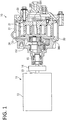
- a scroll compressor 10 shown in FIG. 1 is suitably used for, for example, a brake or an air spring of a railroad car as a compressed air source.
- the scroll compressor 10 includes a fixed scroll 20 fixed to a case (not shown), an orbiting scroll 30 which is caused to revolve with respect to the fixed scroll 20, and a motor 11 providing torque to the orbiting scroll 30.
- the scroll compressor 10 draws air in between the fixed scroll 20 and the orbiting scroll 30 with the motor 11 as a power source and discharges air compressed at compression chambers S formed between the fixed scroll 20 and the orbiting scroll 30.
- the scroll compressor 10 is an oil-free type compressor not using oil for seal, cooling, and lubrication of a scroll, unlike a conventional scroll compressor which compresses, together with air, oil for seal, cooling, and lubrication of a scroll.
- the scroll compressor 10 is accommodated in a case (not shown) together with a fan for cooling the motor 11 or a bearing, a device for cooling and dehumidifying compressed air to be discharged, and an electric box.
- grease is used for the lubrication of the motor 11 or the bearing.
- the motor 11 is configured to include a stator and a rotor accommodated in a motor case 12.
- the motor 11 outputs a torque by energizing the stator and rotating the rotor.
- the torque is transmitted to a shaft 15 that is coupled by a coupling 14 to an output shaft 13 provided to the rotor.
- the shaft 15 is provided at its end portion with an eccentric pin 151 that is eccentric with respect to the shaft center.
- the fixed scroll 20 includes a fixed end plate 200 and a spiral wrap 21 erected on one surface side of the fixed end plate 200.
- the orbiting scroll 30 also includes an orbiting end plate 300 and a spiral wrap 31 erected on one surface side of the orbiting end plate 300.
- the fixed scroll 20 and the orbiting scroll 30 are formed from a metal such as aluminum, an aluminum alloy, and iron (e.g., cast iron or steel). Surfaces of the fixed scroll 20 and the orbiting scroll 30 may be subjected to a surface treatment such as alumite treatment if the scrolls are of an aluminium based material, or quenching and tempering, nitriding, and carburization if the scrolls are of an iron/steel material.
- a surface treatment such as alumite treatment if the scrolls are of an aluminium based material, or quenching and tempering, nitriding, and carburization if the scrolls are of an iron/steel material.
- the orbiting scroll 30 is coupled to the above eccentric pin 151 by a boss 34 provided on a back surface of the orbiting end plate 300.
- the orbiting scroll 30 is caused to revolve with respect to the shaft center of the shaft 15 while being prevented from rotating by an Oldham ring (not shown).
- the wrap 21 of the fixed scroll 20 and the wrap 31 of the orbiting scroll 30 are off-centered from each other by a predetermined amount, and intermeshed out of phase with each other by 180 degrees.
- the compression chambers S are formed point-symmetrically to the central portions (the innermost circumferential portions) of the spirals of the wraps 21 and 31 between the fixed scroll 20 and the orbiting scroll 30.
- a suction inlet IN of air is formed between an end portion at an outermost circumferential portion of the wrap 21 and the wrap 31 and also between an end portion at an outermost circumferential portion of the wrap 31 and the wrap 21.
- the compression chambers S are formed that are filled with the air drawn through the suction inlets IN.
- the compression chambers S are gradually forced to an inner circumferential side while decreasing the volume, with the revolution of the orbiting scroll 30.
- the air inside the compression chambers S is discharged through a discharge port 201 ( FIG. 1 ) formed at the central portion of the spiral on the fixed end plate 200.
- the scroll compressor 10 is a 3D-type scroll compressor, and the volumes of the compression chambers S formed between the both scrolls 20 and 30 decrease also in the height direction of the wraps 21 and 31 in the middle of the spiral.
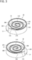
- the height of the wraps 21 and 31 is lower at the inner circumferential side than at the outer circumferential side and the counterpart end plates 300 and 200 that respectively face the wraps 21 and 31 are projected toward the inside more at the inner circumferential side than at the outer circumferential side as shown in FIG. 3 .
- the wraps 21 and 31 respectively have stepped portions 21C and 31C that become lower from the outer circumferential side to the inner circumferential side
- the end plates 300 and 200 respectively have stepped walls 20C and 30C that become taller from the outer circumferential side to the inner circumferential side.
- the stepped walls 20C and 30C are respectively formed in an arc shape in a plan view of the end plates 200 and 300.
- the wrap 21 of the fixed scroll 20 is divided into an inner circumferential wrap 21A positioned in an inner circumferential side of the stepped portion 21C and an outer circumferential wrap 21B positioned in an outer circumferential side of the stepped portion 21C.
- a bottom of the orbiting end plate 300 facing the wrap 21 is segmented into an inner circumferential bottom 30A and an outer circumferential bottom 30B at the stepped wall 30C.
- the wrap 31 of the orbiting scroll 30 is divided into an inner circumferential wrap 31A positioned in an inner circumferential side of the stepped portion 31C and an outer circumferential wrap 31B positioned in an outer circumferential of the stepped portion 31C.
- a bottom of the fixed end plate 200 facing the wrap 31 is segmented into an inner circumferential bottom 20A and an outer circumferential bottom 20B at the stepped wall 20C.
- the inner circumferential wrap 21A of the fixed scroll 20 has an inner circumferential tip seal 41 at its tip.
- the inner circumferential tip seal 41 lies between the inner circumferential wrap 21A and the inner circumferential bottom 30A of the orbiting end plate 300.
- the inner circumferential tip seal 41 is provided along almost the entire length of the inner circumferential wrap 21A from a starting end of the inner circumferential wrap 21A positioned close to the stepped portion 21C to a terminal end of the inner circumferential wrap 21A positioned at the central portion of the spiral.
- the outer circumferential wrap 21B of the fixed scroll 20 has an outer circumferential tip seal 42 at its tip.
- the outer circumferential tip seal 42 lies between the outer circumferential wrap 21B and the outer circumferential bottom 30B of the orbiting end plate 300.
- the outer circumferential tip seal 42 is provided along almost the entire length of the outer circumferential wrap 21B from a starting end of the outer circumferential wrap 21B positioned at an outermost circumferential portion of the spiral to a terminal end of the outer circumferential wrap 21B positioned close to the stepped portion 21C.
- the inner circumferential tip seal 41 and the outer circumferential tip seal 42 are formed to have the same thickness.
- the inner circumferential wrap 31A also has an inner circumferential tip seal 51 at its tip.
- the inner circumferential tip seal 51 lies between the inner circumferential wrap 31A and the inner circumferential bottom 20A of the fixed end plate 200.
- the inner circumferential tip seal 51 is formed similarly to the inner circumferential tip seal 41.
- the outer circumferential wrap 31B has an outer circumferential tip seal 52 at its tip.
- the outer circumferential tip seal 52 lies between the outer circumferential wrap 31B and the outer circumferential bottom 20B of the fixed end plate 200.
- the outer circumferential tip seal 52 is formed similarly to the outer circumferential tip seal 42.
- tip seals 41, 42, 51, and 52 are accommodated in their respective seal grooves D formed in the wraps into which the tip seals are provided as shown in FIG. 4 .
- compressed air is introduced through a gap G between an inner wall of the seal groove D positioned at the inner circumferential side and the tip seal, along the seal groove D to a back surface side of the tip seal. This causes a negative pressure at the surface side of the tip seal relative to the back surface side to lift the tip seal from the seal groove D, thereby pressing the tip seal against the end plate. Then, a clearance between the tip seal and the end plate is sealed, thereby keeping the compression chambers S airtight.
- a material of the inner circumferential tip seals 41 and 51 and a material of the outer circumferential tip seals 42 and 52 are different from each other.
- the material of the inner circumferential tip seals 41 and 51 and the material of the outer circumferential tip seals 42 and 52 are determined based on the temperature and the pressure which rise with the compression of air.
- FIG. 5 shows how the temperature of the wraps 21 and 31 rises with proximity to the central portion (the innermost circumferential portion) from the outermost circumferential portion (0 rad) of the spiral.
- the rotation angle from 0 rad to 2 ⁇ rad corresponds to a rotation angle from the opening to the close of the suction inlets IN.
- the inside of the compression chambers S is under the atmosphere outside the scrolls 20 and 30, and thus the temperature hardly rises.
- the temperature of the wraps 21 and 31 from the outermost circumferential portion to 2 ⁇ rad does not increase beyond about 50°C.
- the temperature shown in FIG. 5 is just an example.
- the temperature and the slope of the temperature rise change in accordance with the volume and the compression ratio of the compression chambers S, and the rotation angle from the outermost circumferential portion to the innermost circumferential portion of the wraps 21 and 31. In any case, the temperature similarly rises slowly from the outermost circumferential portion to 2 ⁇ and rises gradually after exceeding 2 ⁇ toward the central portion.
- the inner circumferential tip seals 41 and 51 disposed at the inner circumferential sides of the wraps 21 and 31 including the central portions of the spirals are required to have heat resistance to withstand high temperatures as above.
- the inner circumferential tip seals 41 and 51 are subjected to high back pressure due to the compressed air compared with the outer circumferential tip seals 42 and 52. As a result, the inner circumferential tip seals 41 and 51 slide while being strongly pressed against the end plates, resulting in a large frictional force between the inner circumferential tip seals 41 and 51 and the end plates. Accordingly, in order to avoid early wear of the inner circumferential tip seals 41 and 51 due to the friction, the inner circumferential tip seals 41 and 51 are also required to have abrasion resistance.
- the inner circumferential tip seals 41 and 51 are disposed at the inner circumferential sides which reach high temperatures and frictional heat acts between the inner circumferential tip seals 41 and 51 and the end plates, the inner circumferential tip seals 41 and 51 undergo a large amount of thermal expansion. Thus, the inner circumferential tip seals 41 and 51 are abraded significantly when pressed against the end plates more strongly. In order to reduce the abrasion loss, it is desirable that the inner circumferential tip seals 41 and 51 have a small linear expansion coefficient.
- the material for the inner circumferential tip seals 41 and 51 is selected from resins and metals satisfying the heat resistance and the abrasion resistance under the conditions of high temperatures and high pressures as described above.
- Resins which may be used for the inner circumferential tip seals 41 and 51 include PI (polyimide), PEEK (polyether ether ketone), and PTFE (polytetrafluoroethylene).
- PI polyimide
- PEEK polyether ether ketone
- PTFE polytetrafluoroethylene
- PAI polyamide imide
- PPS polyphenylene sulfide
- Fillers such as a metal or carbon may be mixed in these resins.
- the inner circumferential tip seals 41 and 51 may be formed by, for example, injection molding from the resins as described above.
- the inner circumferential tip seals 41 and 51 may also be formed by, for example, press blanking from a metal like iron.
- respective materials of the inner circumferential tip seals 41 and 51 may be different from each other. The same applies to the outer circumferential tip seals 42 and 52.
- the heat resistance and the abrasion resistance required for the inner circumferential tip seals 41 and 51 vary in accordance with the temperature and the pressure at the central portion of the spiral.
- the inner circumferential tip seals 41 and 51 preferably have a heat resistant temperature of 240°C or more.
- the outer circumferential tip seals 42 and 52 which are disposed at the outer circumferential sides of the wraps 21 and 31 including the outermost circumferential portions at which air is drawn, rise in temperature by a small amount and are subjected to a smaller back pressure than at the inner circumferential sides, resulting in a small pressing load. Accordingly, the outer circumferential tip seals 42 and 52 may have a smaller heat resistance and abrasion resistance and a higher linear expansion coefficient than those of the inner circumferential tip seals 41 and 51.
- Resins which may be used for the outer circumferential tip seals 42 and 52 include PAI (polyamide imide), PPS (polyphenylene sulfide), and PA (polyamide).
- PAI polyamide imide
- PPS polyphenylene sulfide
- PA polyamide
- Other resins such as PTFE (polytetrafluoroethylene) may also be adopted.
- the outer circumferential tip seals 42 and 52 may also be formed from a metal like iron.
- the inner circumferential tip seals 41 and 51 are formed from a material satisfying at least one requirement of a higher heat resistant temperature, a smaller comparative abrasion quantity, and a smaller linear expansion coefficient than those of the material of the outer circumferential tip seals 42 and 52, as long as the materials satisfy the heat resistances, the abrasion resistances required for the inner circumferential tip seals 41 and 51 and the outer circumferential tip seals 42 and 52 and their balance of thermal expansion.
- the inner circumferential tip seals 41 and 51 and the outer circumferential tip seals 42 and 52 may be formed from materials having comparable heat resistant temperatures and different comparative abrasion quantities or linear expansion coefficients.
- they may be formed from materials having comparable comparative abrasion quantities and different heat resistant temperatures or linear expansion coefficients, or may be formed from materials having comparable linear expansion coefficients and different heat resistant temperatures or comparative abrasion quantities.
- the outer circumferential tip seals 42 and 52 are formed from a material less expensive than that of the inner circumferential tip seals 41 and 51 as long as the inner circumferential tip seals 41 and 51 have durability necessary for the high temperature and the high pressure at the central portion of the spiral and the outer circumferential tip seals 42 and 52 satisfy a necessary heat resistance and abrasion resistance.
- positions of the stepped portions 21C and 31C separating the inner circumferential tip seals 41 and 51 from the outer circumferential tip seals 42 and 52 are set for achieving improved durability and reduced cost of the tip seal in a well-balanced manner.
- the positions of the stepped portions 21C and 31C mean sites at which the outer circumferential wrap 21B erects from the inner circumferential wrap 21A.
- a first index is an angle corresponding to the central value of a temperature range within which the temperatures of wraps 21 and 31 rise.
- a second index is a rotation angle of 2 ⁇ rad, which is obtained by one revolution of the orbiting scroll 30.
- the temperature range of the wraps 21 and 31 ranges from 25°C at 0 rad to 225°C at about 7 ⁇ rad with the central value at 125°C.
- the rotation angle corresponding to the central value at 125°C is 4 ⁇ rad (the first index).
- the rotation angle of 2 ⁇ rad (the second index) corresponding to one revolution corresponds to the rotation angle from the opening to the close of the suction inlets IN at the outermost circumferential portions of the wraps 21 and 31.
- the value 2 ⁇ rad is used to ensure the cost reduction effect obtained by selecting an inexpensive material for the outer circumferential tip seals 42 and 52.
- the positions of the stepped portions 21C and 31C are each preferably set within a range of 2 ⁇ rad or more and 4 ⁇ rad or less in the inner circumferential sides from the outermost circumferential portions of the wraps 21 and 31.
- the heat resistant temperature of the outer circumferential tip seals 42 and 52 can be kept to temperatures equal to or lower than the central value of the temperature rise range.
- the length of the outer circumferential tip seals 42 and 52 of 2 ⁇ rad or more can be assured. This can ensure the cost reduction effect by selecting an inexpensive material for the outer circumferential tip seals 42 and 52.
- the positions of the stepped portions 21C and 31C are set at 2 ⁇ in the present embodiment, but the stepped portions 21C and 31C may be provided at any position in a range of 2 ⁇ rad or more and 4 ⁇ rad or less from the outermost circumferential portions of the wraps 21 and 31.
- the stepped portions 21C and 31C are positioned 3 ⁇ rad or more in the inner circumferential sides from the outermost circumferential portions, the stepped portions 21C and 31C do not exist in the compression chambers S when the suction inlets IN are closed to close up the compression chambers S.
- the compression chambers S each form a space having a uniform dimension between the end plates 200 and 300 with no volume reduction in the height direction of the wraps 21 and 31. This can maximize the volume of the compression chambers S positioned in the outermost circumferential portions, thereby ensuring a large compression ratio.
- the inner circumferential tip seals 41 and 51 and the outer circumferential tip seals 42 and 52 set apart and separated by the stepped portions 21C and 31C of the wraps 21 and 31, the inner circumferential tip seals 41 and 51 are formed from a material determined by the high temperature and high pressure at the central portions of the spirals, while the outer circumferential tip seals 42 and 52 are formed from an inexpensive material.
- the wraps 21 and 31 and the end plates 300 and 200 can be kept sealed therebetween without causing erosion, an abnormal abrasion, or a seizure to the tip seals, thereby ensuring the reliability of the scroll compressor 10 as well as contributing to cost reduction.
- the second embodiment will be described mainly focusing on points different from those in the first embodiment. Configurations similar to those in the first embodiment will be given the same characters.
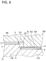
- the inner circumferential tip seals 41 and 51 are coated with an abrasion-resistant material instead of differentiating the materials between the inner circumferential tip seals 41 and 51 and the outer circumferential tip seals 42 and 52.
- the inner circumferential tip seal 41 has an abrasion resistant coating 45 on a surface.
- a material of the coating 45 to be used include PTFE (polytetrafluoroethylene), PEEK (polyether ether ketone), DLC (diamond-like carbon), TiN (titanium nitride), and CrN (chromium nitride).
- the abrasion resistance of the coating 45 is determined as appropriate according to the pressure at the central portion of the spiral.
- a film thickness of the coating 45 may be set according to the comparative abrasion quantity required for the coating 45.
- the coating 45 at least forms a surface 45S (surface) facing the inner circumferential bottom 30A of the end plate 300, and faces the counterpart end plate 300.
- the material of the portion of the inner circumferential tip seal 41 facing the end plate 300 (coating 45) is different from that of the portion of the outer circumferential tip seal 42 without a coating facing the end plate 300.
- the inner circumferential tip seal 51 may be provided with a coating 45 similar to that of the inner circumferential tip seal 41.
- a coating 45 of PTFE or PEEK may be formed by spraying and applying a liquid material prepared by mixing resin powder into a solution onto the inner circumferential tip seals 41 and 51 (base material) with an air spray gun and then heating the applied liquid material at a melting point of the resin or higher to fuse it with the inner circumferential tip seals 41 and 51.
- the liquid material is repeatedly applied and heated until a predetermined film thickness is obtained.
- an electrostatic powder coating method of applying resin powder to a base material using static electricity, a dip method, and the like may be used. In any case, resin is fused with a base material by applying heat.
- a coating 45 of DLC may be formed by plasma-enhanced chemical vapor deposition (PECVD) or physical vapor deposition (PVD).
- PECVD plasma-enhanced chemical vapor deposition
- PVD physical vapor deposition
- a coating 45 of TiN or CrN may be formed by PVD.
- the material for the base materials for the inner circumferential tip seals 41 and 51 on which the coating 45 is formed one that does not melt by heat applied during the process of forming the coating 45 is selected.
- the base materials of the inner circumferential tip seals 41 and 51 may be made of the same material as that of the outer circumferential tip seals 42 and 52.
- abrasion resistance higher than that of the outer circumferential tip seals 42 and 52 can be imparted to the inner circumferential tip seals 41 and 51 by applying the coating 45 to the inner circumferential tip seals 41 and 51. Therefore, necessary abrasion resistance can be achieved while holding down the material cost by forming the base material of the inner circumferential tip seals 41 and 51 from the same material as that of the outer circumferential tip seals 42 and 52.
- abrasion resistance can be further improved by selecting such a material as the material for the coating 45.
- the coefficient of friction of the surfaces of the inner circumferential tip seals 41 and 51 reduces.
- DLC has a coefficient of friction of about 0.1 (dry condition), for example.
- the abrasion resistance can be increased also in that the abrasion loss reduces due to the small coefficient of friction.
- the base materials of the inner circumferential tip seals 41 and 51 may be formed from a material different from that of the outer circumferential tip seals 42 and 52.
- the third embodiment will be described also mainly focusing on points different from those in the first embodiment, and configurations similar to those already described will be given the same characters.
- the inner circumferential tip seals and the outer circumferential tip seals are different in thickness.
- the inner circumferential tip seals and the outer circumferential tip seals are the same in material.
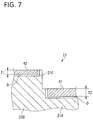
- the inner circumferential tip seal 61 provided to the inner circumferential wrap 21A and the outer circumferential tip seal 42 provided to the outer circumferential wrap 21B are different in thickness. It is to be noted that the inner circumferential tip seal provided to the inner circumferential wrap 31A is formed similarly to the inner circumferential tip seal 61, and the outer circumferential tip seal provided to the outer circumferential wrap 31B is formed similarly to the outer circumferential tip seal 42.
- a thickness of the outer circumferential tip seal 42 is set to T1 in the depth direction of the seal groove D. This thickness is the same as that of the outer circumferential tip seal 42 in the first and second embodiments.
- a thickness T2 of the inner circumferential tip seal 61 is larger than the thickness T1 of the outer circumferential tip seal 42.
- the inner circumferential tip seal 61 if made thick, can leave a thickness sufficient for the seal even when greatly abraded. This ensures the reliability of the tip seal.
- the thickness T1 of the outer circumferential tip seal 42 can be kept sufficient for the seal, thereby holding down the cost.
- the third embodiment may be combined with the first or second embodiment. That is, in the third embodiment, the inner circumferential tip seals 41 and 51 may be formed from a material different from that of the outer circumferential tip seals 42 and 52, or the inner circumferential tip seals 41 and 51 may be provided with the coating 45.
- durability to withstand the high temperature and high pressure at the inner circumferential side of the wraps can be imparted to the inner circumferential tip seals, thereby improving the reliability of the scroll compressor.
- the temperature and the compression ratio may become as high as those in air-compressing scroll compressors at the central portions of the spirals.
- the present invention has a great effect even in such a case.
- the effect of the present invention is also pronounced in oil-free scroll compressors that compress a refrigerant like that.
- the stepped portion is provided only at one site in a circumferential direction of each wrap in the scroll compressors of the first to third embodiments, the stepped portions may be provided at a plurality of sites in the circumferential direction of the wrap.
- stepped portions 211 and 212 are provided at two sites in the circumferential direction of the wrap 21 as shown in FIG. 8 , there exist an innermost circumferential tip seal 71 provided at a position including the innermost circumferential portion (the central portion of the spiral), an outermost circumferential tip seal 73 provided at a position including the outermost circumferential portion, and an intermediate tip seal 72 provided at an intermediate position.
- first stepped portion 211 when one of the two stepped portions 211 and 212 that is positioned at the outer circumferential side is called a first stepped portion 211 and one positioned at the inner circumferential side is called a second stepped portion 212, the intermediate tip seal 72 and the innermost circumferential tip seal 71 positioned in the inner circumferential side of the first stepped portion 211 and the outermost circumferential tip seal 73 positioned in the outer circumferential side of the first stepped portion 211 may be different in material or thickness, based on the first stepped portion 211.
- the innermost circumferential tip seal 71 positioned in the inner circumferential side of the second stepped portion 212 and the intermediate tip seal 72 and the outermost circumferential tip seal 73 positioned in the outer circumferential side of the second stepped portion 212 may be different in material or thickness, based on the second stepped portion 212.
- outermost circumferential tip seal 73, the intermediate tip seal 72, and the innermost circumferential tip seal 71 may be different stepwise in material or thickness.
- the intermediate tip seal 72 positioned in the inner circumferential side of the first stepped portion 211 and the outermost circumferential tip seal 73 positioned in the outer circumferential side of the first stepped portion 211 may be different in material or thickness and at the same time the innermost circumferential tip seal 71 positioned in the inner circumferential side of the second stepped portion 212 and the intermediate tip seal 72 positioned in the outer circumferential side of the second stepped portion 212 may be different in material or thickness.
- the temperature and the pressure of the gas rise from the outermost circumferential portion toward the innermost circumferential portion of each wrap, the temperature and the pressure become higher at more inward portions. Therefore, it may be configured such that the material of the inner circumferential tip seals positioned relatively more inwardly is more excellent in heat resistance and abrasion resistance than the material of the outer circumferential tip seals positioned relatively outwardly and that the inner circumferential tip seal is thicker than the outer circumferential tip seal.
- the scroll compressor of the present invention is not limited to one powered by motor torque, and may be powered by a driving force transmitted from an engine through a belt to the shaft.
Landscapes
- Engineering & Computer Science (AREA)
- Mechanical Engineering (AREA)
- General Engineering & Computer Science (AREA)
- Rotary Pumps (AREA)
- Applications Or Details Of Rotary Compressors (AREA)
Abstract
Description
- The present invention relates to a scroll compressor.
- A scroll compressor is equipped with a fixed scroll and an orbiting scroll. Each of the fixed scroll and the orbiting scroll is a disk-shaped end plate provided with a spiral wrap on one surface side. Such a fixed scroll and an orbiting scroll are arranged to face each other with their wraps intermeshed, and the orbiting scroll is caused to revolve with respect to the fixed scroll. Then, a compression chamber between both of the scrolls is filled with a gas drawn through the outermost circumferential portions of the wraps. The gas is compressed as the volume of the compression chamber decreases with the revolution of the orbiting scroll. The gas is discharged through a port positioned at the central portion of the end plate in a maximally compressed state.
- In general, the fixed scroll and the orbiting scroll are each provided with a tip seal at its tip of the wrap. The compressed gas is introduced into seal grooves accommodating the tip seals. Each tip seal is pressed against the end plate by a back pressure caused by the compressed gas to seal a clearance between the wraps and the end plates.
- In a scroll compressor described in Patent Literature 1, a tip seal is divided into two parts in a circumferential direction, and the divided two seals are connected together. The tip seal positioned at an inner circumferential side of each wrap is formed from a material more excellent in heat-resistance and abrasion-resistance than that of the tip seal positioned at an outer circumferential side.
- In the meantime, there is a scroll compressor formed such that a wrap is shorter at an inner circumferential side than at an outer circumferential side and a counterpart end plate correspondingly projects toward the inside more at the inner circumferential side than at the outer circumferential side in order to decrease the volume of a compression chamber not only in a circumferential direction but also in a height direction, thereby achieving a high compression ratio (Patent Literature 2). In this type of a scroll compressor called 3D Scroll®, a step is formed at both wraps and end plates.
- In such a three-dimensional type (3D type) scroll compressor, each tip seal is placed as divided into portions at the inner and outer circumferential sides of the step of the wrap as described in Patent Literature 2.
-
- Patent Literature 1:
Japanese Utility Model Laid-Open No. 2-124201 - Patent Literature 2:
Japanese Patent Laid-Open No. 2011- 144801 - In a scroll compressor, temperature and pressure rise with proximity to the central portion of a scroll. Each tip seal is required to have high abrasion resistance and heat resistance to endure the pressing load and high temperature due to the high pressure at the central portion.
- In general, however, a material having high abrasion resistance and heat resistance is expensive, so the material for the tip seals is selected in consideration of the cost.
- Here, the division of the tip seals as in Paten Literature 1 increases the number of parts, and thus this requires the cost of joining the tip seals together. Generally, in the case of an ordinary scroll compressor of not 3D type as in Patent Literature 1, an integral tip seal formed from the same material is provided along the entire length of each wrap from the outermost circumferential portion to the innermost circumferential portion.
- In contrast, in the case of a 3D-type scroll compressor, it is hard to form a tip seal integrally on both sides (inward and outward) of the step of each wrap. As a result, in the 3D-type scroll compressor, each tip seal is inevitably divided into portions at inner and outer circumferential sides of the step of the wrap as in Patent Literature 2.
- The present invention has been made in view of that in the 3D-type scroll compressor, each tip seal is divided into portions on both sides of the step of the wrap, and aims to improve the reliability of the 3D-type scroll compressor by improving the durability of the tip seals.
- The present invention is a scroll compressor including a fixed scroll and an orbiting scroll, the fixed scroll and the orbiting scroll each having a spiral wrap configured to decrease in height from an outer circumferential side to an inner circumferential side via a stepped portion and an end plate having a stepped wall being erected following the stepped portion of the counterpart wrap.
- In the present invention, an inner circumferential tip seal provided in an inner circumferential side of the stepped portion and lying between the wrap and the counterpart end plate and an outer circumferential tip seal provided in an outer circumferential side of the stepped portion and lying between the wrap and the counterpart end plate are different in material at least at portions facing the end plate.
- According to the present invention, among the tip seals formed as inevitably divided into portions on both sides of the stepped portion of each wrap of a 3D scroll, only the inner circumferential tip seal can be formed from a material satisfying a desired condition based on the temperature and the pressure of the central portion of each scroll, and the outer circumferential tip seal can be formed from other, inexpensive material.
- Also, in the 3D-type scroll compressor, it is assumed that the inner circumferential tip seal and the outer circumferential tip seal are placed as set apart and separated by the stepped portion, and thus such a scroll compressor does not require the cost of joining both the inner and outer circumferential tip seals together.
- Therefore, according to the present invention, the durability of the tip seals can be improved while holding down the cost, compared with the case in which both the inner and outer circumferential tip seals are formed from the same material.
- An object of the present invention can be achieved if the inner circumferential tip seal and the outer circumferential tip seal are formed from different materials at least at the portions facing the end plate.
- In the scroll compressor of the present invention, it is preferable that the stepped portion be positioned in an outer circumferential side of a rotation angle corresponding to a central value of a temperature range within which a temperature of the wrap rises from a rotation angle at an outermost circumferential portion of the wrap to a rotation angle at an innermost circumferential portion of the wrap, and that the inner circumferential tip seal be formed from a material satisfying at least one requirement of a higher heat resistant temperature, a smaller comparative abrasion quantity, and a smaller linear expansion coefficient than those of a material of the outer circumferential tip seal.
- The term "heat resistant temperature" means an upper-limit temperature causing no change in appearance or no decrease in mechanical properties to a tip seal when it is used continuously.
- The term "comparative abrasion quantity" is obtained by dividing the abrasion quantity expressed in volume by the distance a tip seal has slid and the vertical load.
- A material that is hardly abraded has a small comparative abrasion quantity. Also, a tip seal formed of a material having a small linear expansion coefficient can avoid being strongly pressed against the end plate due to the heat expansion, and is therefore hardly abraded. In the present invention, the comparative abrasion quantity and the linear expansion coefficient are measures associated with the abrasion resistance showing how small a volume is that is reduced under friction.
- The term "durability" of a tip seal as used herein includes heat resistance expressed by the heat resistant temperature, and the above abrasion resistance.
- The present invention also encompasses a configuration in which the materials of each of the inner circumferential tip seal and the outer circumferential tip seal are different only at the portions facing the end plate.
- Examples of such a configuration include one in which a heat resistant temperature of a material of the portion of the inner circumferential tip seal facing the end plate is higher than that of a material of the portion of the outer circumferential tip seal facing the end plate, one in which a comparative abrasion quantity of a material of the portion of the inner circumferential tip seal facing the end plate is smaller than that of a material of the portion of the outer circumferential tip seal facing the end plate, and one in which a linear expansion coefficient of a material of the portion of the inner circumferential tip seal facing the end plate is smaller than that of a material of the portion of the outer circumferential tip seal facing the end plate. The present invention can contribute to improving the durability of the inner circumferential tip seal by any of these configurations.
- The durability of each tip seal can be improved if the material of the inner circumferential tip seal satisfies one of the requirements above.
- Further, because the heat resistant temperature of the outer circumferential tip seal can be kept to be a temperature equal to or lower than the central value of the temperature rise range, a less inexpensive material whose heat resistant temperature is not so high can be selected as the material for the outer circumferential tip seal.
- In the scroll compressor of the present invention, it is preferable that the stepped portion be positioned in an outer circumferential side of the rotation angle corresponding to the central value of the temperature range within which the temperature of the wrap rises from the rotation angle at the outermost circumferential portion of the wrap to the rotation angle at the innermost circumferential portion of the wrap, and that the inner circumferential tip seal be formed from a coating of an abrasion-resistant material at least at a portion facing the end plate.
- The term "coating" means a film provided on a surface of the base material of a tip seal by any method such as painting, plating, sputtering, chemical vapor deposition, and physical vapor deposition. The coating can be constituted by one or more layers provided on the surface of the base material.
- Abrasion resistance higher than that of the outer circumferential tip seal can be imparted to the inner circumferential tip seal by forming the inner circumferential tip seal from the coating at least at the portion facing the end plate. Therefore, necessary abrasion resistance can be achieved while holding down the material cost by forming the base material of the inner circumferential tip seal from the same material for the base material of the outer circumferential tip seal.
- Also, even if it is difficult to use a material more excellent in abrasion-resistance than the material that can be used for the base material, for the material of the base material of the tip seal, the abrasion resistance can be further improved by selecting such a material as the material for the coating.
- Further, if the application of the coating can give a surface that is smoother than that of the base material, the coefficient of friction of the surface of the inner circumferential tip seal reduces. The abrasion resistance can also be enhanced in that the abrasion loss is reduced.
- In the scroll compressor of the present invention, it is preferable that the stepped portion be positioned in an outer circumferential side of the rotation angle corresponding to the central value of the temperature range within which the temperature of the wrap rises from the rotation angle at the outermost circumferential portion of the wrap to the rotation angle at the innermost circumferential portion of the wrap, and that a thickness dimension of the inner circumferential tip seal be greater than a thickness dimension of the outer circumferential tip seal.
- Because the tip seals slide against the end plate while being pressed against it to be gradually abraded, they are replaced periodically. The inner circumferential tip seal, which is subjected to a large pressing load due to back pressure, is abraded more easily than the outer circumferential tip seal.
- Then, the inner circumferential tip seal, if made thick, can leave a thickness sufficient for the seal even when greatly abraded. This can ensure the reliability of the tip seal as well as decreasing the frequency of the replacement.
- In addition, the thickness of the outer circumferential tip seal can be kept sufficient for the seal, thereby holding down the cost.
- The scroll compressor of the present invention includes a fixed scroll and an orbiting scroll, the fixed scroll and the orbiting scroll each having a spiral wrap configured to decrease in height from an outer circumferential side to an inner circumferential side via a stepped portion, and an end plate having a stepped wall being erected following the stepped portion of the counterpart wrap, in which a thickness dimension of an inner circumferential tip seal provided in an inner circumferential side of the stepped portion and lying between the wrap and the counterpart end plate is greater than a thickness dimension of an outer circumferential tip seal provided in an outer circumferential side of the stepped portion and lying between the wrap and the counterpart end plate.
- The present invention also utilizes the fact that in a 3D-type scroll compressor, each tip seal is divided into portions on both sides of a step of a wrap.
- In the case of an ordinary scroll compressor without any step formed on the wraps, if the inner circumferential tip seal and the outer circumferential tip seal are different in thickness, a bottom of each seal groove accommodating the tip seal is stepped as well as joining the inner circumferential tip seal and the outer circumferential tip seal together. In this case, the position of the step in the seal groove and the position of the joint of the tip seals are easily misaligned to cause leakage.
- In the present invention, among the tip seals formed as inevitably divided into portions on both sides of the stepped portion of the wrap of the 3D scroll, the thickness of the inner circumferential tip seal is made greater than that of the outer circumferential tip seal.
- Then, even if the inner circumferential tip seal, which is subjected to a large pressing load due to back pressure, is greatly abraded, the inner circumferential tip seal can leave a thickness sufficient for the seal. This improves the durability and the reliability of the tip seals.
- In addition, the thickness of the outer circumferential tip seal can be kept sufficient for the seal, thereby holding down the cost.
- In each of the above scroll compressors, it is preferable that the stepped portion be positioned within a rotation angle range exceeding 2π in an inner circumferential side from the rotation angle at the outermost circumferential portion of the wrap.
- The value 2π corresponds to a rotation angle obtained by one revolution of the orbiting scroll. While the orbiting scroll makes one revolution, suction inlets open at the outermost circumferential portions of the wraps and then close again.
- If the stepped portion is positioned exceeding 2π from the outermost circumferential portion, the length of the outer circumferential tip seal of 2π or more can be assured. This can ensure the cost reduction effect by using an inexpensive material for the outer circumferential tip seal.
- Also, it is preferable that the stepped portion be positioned within a rotation angle range exceeding 3π in an inner circumferential side from the rotation angle at the outermost circumferential portion of the wrap.
- If the stepped portion is positioned exceeding 3π from the outermost circumferential portion, the stepped portion does not exist in compression chambers when the suction inlets are closed to close up the compression chambers, and the compression chambers would not decrease in volume in the height direction of the wrap. This can maximize the volume of the compression chambers positioned at the outermost circumferential portion, thereby ensuring a large compression ratio.
- The scroll compressor of the present invention can compress any working fluid such as a refrigerant and air, but is especially preferably used in an air-compressing scroll compressor. If used for compressing air, the temperature rises significantly at the central portion of each scroll, and thus the present invention, which can impart durability to the inner circumferential tip seal, has a great effect.
- Also, the present invention can be applied to both a scroll compressor using an oil for seal, cooling, and lubrication of the scroll and a scroll compressor of an oil-free type not using oil, but is especially useful when applied to the oil-free type scroll compressor. This is because in the oil-free type scroll compressor, the tip seals slide directly against the end plate without an oil (lubricant), and thus the temperature rises significantly at the inner circumferential side.
- Therefore, the effect of the present invention is pronounced when the present invention is applied to an air-compressing, oil-free scroll compressor.
- According to the present invention, a 3D-type scroll compressor with improved reliability can be provided by improving the durability of a tip seal.
-
- [
FIG. 1] FIG. 1 is a view showing a scroll compressor according to a first embodiment, which is partially cut away to show a main part. - [
FIG. 2] FIG. 2 is a plan view showing respective wraps of a fixed scroll and an orbiting scroll with the wrap of the orbiting scroll being partially cut away. - [
FIG. 3] FIG. 3 is a perspective view of the fixed scroll and the orbiting scroll. - [
FIG. 4] FIG. 4 is a cross-sectional view showing the wrap and an end plate at a stepped portion. - [
FIG. 5] FIG. 5 is a graph showing a relation between a rotation angle of the wrap and a temperature of the wrap. - [
FIG. 6] FIG. 6 is a cross-sectional view showing a wrap and an end plate at a stepped portion in a scroll compressor of a second embodiment. - [
FIG. 7] FIG. 7 is a cross-sectional view showing a wrap and an end plate at a stepped portion in a scroll compressor of a third embodiment. - [
FIG. 8] FIG. 8 is a schematic view showing a modified example of the present invention. - Hereinafter, embodiments of the present invention will be described with reference to the attached drawings.
- A
scroll compressor 10 shown inFIG. 1 is suitably used for, for example, a brake or an air spring of a railroad car as a compressed air source. - The
scroll compressor 10 includes a fixedscroll 20 fixed to a case (not shown), an orbitingscroll 30 which is caused to revolve with respect to the fixedscroll 20, and amotor 11 providing torque to theorbiting scroll 30. - The
scroll compressor 10 draws air in between the fixedscroll 20 and the orbitingscroll 30 with themotor 11 as a power source and discharges air compressed at compression chambers S formed between the fixedscroll 20 and the orbitingscroll 30. - The
scroll compressor 10 is an oil-free type compressor not using oil for seal, cooling, and lubrication of a scroll, unlike a conventional scroll compressor which compresses, together with air, oil for seal, cooling, and lubrication of a scroll. - The
scroll compressor 10 is accommodated in a case (not shown) together with a fan for cooling themotor 11 or a bearing, a device for cooling and dehumidifying compressed air to be discharged, and an electric box. - It is to be noted that grease is used for the lubrication of the
motor 11 or the bearing. - The
motor 11 is configured to include a stator and a rotor accommodated in amotor case 12. - The
motor 11 outputs a torque by energizing the stator and rotating the rotor. The torque is transmitted to ashaft 15 that is coupled by acoupling 14 to anoutput shaft 13 provided to the rotor. - The
shaft 15 is provided at its end portion with aneccentric pin 151 that is eccentric with respect to the shaft center. - The fixed
scroll 20 includes afixed end plate 200 and aspiral wrap 21 erected on one surface side of thefixed end plate 200. - The orbiting
scroll 30 also includes an orbitingend plate 300 and aspiral wrap 31 erected on one surface side of the orbitingend plate 300. - The fixed
scroll 20 and the orbitingscroll 30 are formed from a metal such as aluminum, an aluminum alloy, and iron (e.g., cast iron or steel). Surfaces of the fixedscroll 20 and the orbitingscroll 30 may be subjected to a surface treatment such as alumite treatment if the scrolls are of an aluminium based material, or quenching and tempering, nitriding, and carburization if the scrolls are of an iron/steel material. - The orbiting
scroll 30 is coupled to the aboveeccentric pin 151 by aboss 34 provided on a back surface of the orbitingend plate 300. When theshaft 15 rotates, the orbitingscroll 30 is caused to revolve with respect to the shaft center of theshaft 15 while being prevented from rotating by an Oldham ring (not shown). - As shown in
FIG. 2 , thewrap 21 of the fixedscroll 20 and thewrap 31 of the orbitingscroll 30 are off-centered from each other by a predetermined amount, and intermeshed out of phase with each other by 180 degrees. - The compression chambers S are formed point-symmetrically to the central portions (the innermost circumferential portions) of the spirals of the
wraps scroll 20 and the orbitingscroll 30. - When the orbiting
scroll 30 revolves from the state shown inFIG. 2 , a suction inlet IN of air is formed between an end portion at an outermost circumferential portion of thewrap 21 and thewrap 31 and also between an end portion at an outermost circumferential portion of thewrap 31 and thewrap 21. - When the suction inlets IN are closed to the state shown in
FIG. 2 with the revolution of the orbitingscroll 30, the compression chambers S are formed that are filled with the air drawn through the suction inlets IN. The compression chambers S are gradually forced to an inner circumferential side while decreasing the volume, with the revolution of the orbitingscroll 30. The air inside the compression chambers S is discharged through a discharge port 201 (FIG. 1 ) formed at the central portion of the spiral on thefixed end plate 200. - The
scroll compressor 10 is a 3D-type scroll compressor, and the volumes of the compression chambers S formed between the bothscrolls wraps scroll 20 and the orbitingscroll 30, the height of thewraps counterpart end plates wraps FIG. 3 . - Accordingly, the
wraps portions end plates walls walls end plates - The
wrap 21 of the fixedscroll 20 is divided into an innercircumferential wrap 21A positioned in an inner circumferential side of the steppedportion 21C and an outercircumferential wrap 21B positioned in an outer circumferential side of the steppedportion 21C. - A bottom of the orbiting
end plate 300 facing thewrap 21 is segmented into an innercircumferential bottom 30A and an outercircumferential bottom 30B at the steppedwall 30C. - Also, the
wrap 31 of the orbitingscroll 30 is divided into an innercircumferential wrap 31A positioned in an inner circumferential side of the steppedportion 31C and an outercircumferential wrap 31B positioned in an outer circumferential of the steppedportion 31C. - A bottom of the
fixed end plate 200 facing thewrap 31 is segmented into an innercircumferential bottom 20A and an outercircumferential bottom 20B at the steppedwall 20C. - Hereinafter, a tip seal provided to each of the
wraps - As shown in
FIG. 3 , the innercircumferential wrap 21A of the fixedscroll 20 has an innercircumferential tip seal 41 at its tip. The innercircumferential tip seal 41 lies between the innercircumferential wrap 21A and the innercircumferential bottom 30A of the orbitingend plate 300. The innercircumferential tip seal 41 is provided along almost the entire length of the innercircumferential wrap 21A from a starting end of the innercircumferential wrap 21A positioned close to the steppedportion 21C to a terminal end of the innercircumferential wrap 21A positioned at the central portion of the spiral. - Also, the outer
circumferential wrap 21B of the fixedscroll 20 has an outercircumferential tip seal 42 at its tip. The outercircumferential tip seal 42 lies between the outercircumferential wrap 21B and the outercircumferential bottom 30B of the orbitingend plate 300. The outercircumferential tip seal 42 is provided along almost the entire length of the outercircumferential wrap 21B from a starting end of the outercircumferential wrap 21B positioned at an outermost circumferential portion of the spiral to a terminal end of the outercircumferential wrap 21B positioned close to the steppedportion 21C. - In the embodiment, the inner
circumferential tip seal 41 and the outercircumferential tip seal 42 are formed to have the same thickness. - As for the orbiting
scroll 30, the innercircumferential wrap 31A also has an innercircumferential tip seal 51 at its tip. The innercircumferential tip seal 51 lies between the innercircumferential wrap 31A and the innercircumferential bottom 20A of thefixed end plate 200. The innercircumferential tip seal 51 is formed similarly to the innercircumferential tip seal 41. - Also, the outer
circumferential wrap 31B has an outercircumferential tip seal 52 at its tip. The outercircumferential tip seal 52 lies between the outercircumferential wrap 31B and the outercircumferential bottom 20B of thefixed end plate 200. The outercircumferential tip seal 52 is formed similarly to the outercircumferential tip seal 42. - These tip seals 41, 42, 51, and 52 are accommodated in their respective seal grooves D formed in the wraps into which the tip seals are provided as shown in
FIG. 4 . In each of the seal grooves D, compressed air is introduced through a gap G between an inner wall of the seal groove D positioned at the inner circumferential side and the tip seal, along the seal groove D to a back surface side of the tip seal. This causes a negative pressure at the surface side of the tip seal relative to the back surface side to lift the tip seal from the seal groove D, thereby pressing the tip seal against the end plate. Then, a clearance between the tip seal and the end plate is sealed, thereby keeping the compression chambers S airtight. - In the present embodiment, a material of the inner circumferential tip seals 41 and 51 and a material of the outer circumferential tip seals 42 and 52 are different from each other.
- The material of the inner circumferential tip seals 41 and 51 and the material of the outer circumferential tip seals 42 and 52 are determined based on the temperature and the pressure which rise with the compression of air.
-
FIG. 5 shows how the temperature of thewraps - The rotation angle from 0 rad to 2π rad corresponds to a rotation angle from the opening to the close of the suction inlets IN. Within the angular range of rotation, the inside of the compression chambers S is under the atmosphere outside the
scrolls FIG. 5 , the temperature of thewraps - When the rotation angle exceeds 2π rad to start the compression within the compression chambers S, the temperature of the
wraps - The temperature shown in
FIG. 5 is just an example. The temperature and the slope of the temperature rise change in accordance with the volume and the compression ratio of the compression chambers S, and the rotation angle from the outermost circumferential portion to the innermost circumferential portion of thewraps - The inner circumferential tip seals 41 and 51 disposed at the inner circumferential sides of the
wraps - Also, the inner circumferential tip seals 41 and 51 are subjected to high back pressure due to the compressed air compared with the outer circumferential tip seals 42 and 52. As a result, the inner circumferential tip seals 41 and 51 slide while being strongly pressed against the end plates, resulting in a large frictional force between the inner circumferential tip seals 41 and 51 and the end plates. Accordingly, in order to avoid early wear of the inner circumferential tip seals 41 and 51 due to the friction, the inner circumferential tip seals 41 and 51 are also required to have abrasion resistance.
- Further, because the inner circumferential tip seals 41 and 51 are disposed at the inner circumferential sides which reach high temperatures and frictional heat acts between the inner circumferential tip seals 41 and 51 and the end plates, the inner circumferential tip seals 41 and 51 undergo a large amount of thermal expansion. Thus, the inner circumferential tip seals 41 and 51 are abraded significantly when pressed against the end plates more strongly. In order to reduce the abrasion loss, it is desirable that the inner circumferential tip seals 41 and 51 have a small linear expansion coefficient.
- Here, back pressure and thermal expansion are different between the inner circumferential tip seals 41 and 51 and the outer circumferential tip seals 42 and 52. Accordingly, even when the inner circumferential tip seals 41 and 51 are being pressed against the
end plates end plates - The material for the inner circumferential tip seals 41 and 51 is selected from resins and metals satisfying the heat resistance and the abrasion resistance under the conditions of high temperatures and high pressures as described above.
- Resins which may be used for the inner circumferential tip seals 41 and 51 include PI (polyimide), PEEK (polyether ether ketone), and PTFE (polytetrafluoroethylene). Other resins such as PAI (polyamide imide) and PPS (polyphenylene sulfide) may also be adopted. Fillers such as a metal or carbon may be mixed in these resins.
- The inner circumferential tip seals 41 and 51 may be formed by, for example, injection molding from the resins as described above.
- The inner circumferential tip seals 41 and 51 may also be formed by, for example, press blanking from a metal like iron.
- Here, respective materials of the inner circumferential tip seals 41 and 51 may be different from each other. The same applies to the outer circumferential tip seals 42 and 52.
- A heat resistant temperature and a linear expansion coefficient of each material under continuous use will be exemplified below.
- PI (example): 240°C, 1.7 to 4.5 × 10⁻⁵/°C
- PEEK (example): 260°C, 3.0 to 5.7 × 10⁻⁵/°C
- PTFE (example): 260°C, 8.3 to 15.2 × 10⁻⁵/°C
- PAI (example): 250°C, 4.0 × 10⁻⁵/°C
- PPS (example): 230°C, 1.8 to 8.7 × 10⁻⁵/°C
- The heat resistance and the abrasion resistance required for the inner circumferential tip seals 41 and 51 vary in accordance with the temperature and the pressure at the central portion of the spiral.
- In the example shown in
FIG. 5 , the inner circumferential tip seals 41 and 51 preferably have a heat resistant temperature of 240°C or more. - On the other hand, the outer circumferential tip seals 42 and 52, which are disposed at the outer circumferential sides of the
wraps - Resins which may be used for the outer circumferential tip seals 42 and 52 include PAI (polyamide imide), PPS (polyphenylene sulfide), and PA (polyamide). Other resins such as PTFE (polytetrafluoroethylene) may also be adopted.
- The outer circumferential tip seals 42 and 52 may also be formed from a metal like iron.
- In the present embodiment, the inner circumferential tip seals 41 and 51 are formed from a material satisfying at least one requirement of a higher heat resistant temperature, a smaller comparative abrasion quantity, and a smaller linear expansion coefficient than those of the material of the outer circumferential tip seals 42 and 52, as long as the materials satisfy the heat resistances, the abrasion resistances required for the inner circumferential tip seals 41 and 51 and the outer circumferential tip seals 42 and 52 and their balance of thermal expansion.
- Accordingly, the inner circumferential tip seals 41 and 51 and the outer circumferential tip seals 42 and 52 may be formed from materials having comparable heat resistant temperatures and different comparative abrasion quantities or linear expansion coefficients.
- Alternatively, they may be formed from materials having comparable comparative abrasion quantities and different heat resistant temperatures or linear expansion coefficients, or may be formed from materials having comparable linear expansion coefficients and different heat resistant temperatures or comparative abrasion quantities.
- Here, only two combination examples of the material which may be used for the inner circumferential tip seals 41 and 51 and the material which may be used for the outer circumferential tip seals 42 and 52 are shown.
- (1) material of inner circumferential tip seal: PI, material of outer circumferential tip seal: PPS
- (2) material of inner circumferential tip seal: ferrous metal, material of outer circumferential tip seal: PA
- In the embodiment, the outer circumferential tip seals 42 and 52 are formed from a material less expensive than that of the inner circumferential tip seals 41 and 51 as long as the inner circumferential tip seals 41 and 51 have durability necessary for the high temperature and the high pressure at the central portion of the spiral and the outer circumferential tip seals 42 and 52 satisfy a necessary heat resistance and abrasion resistance.
- Here, positions of the stepped
portions - The positions of the stepped
portions circumferential wrap 21B erects from the innercircumferential wrap 21A. - In determining the positions of the stepped
portions wraps scroll 30. - In the example of
FIG. 5 , the temperature range of thewraps - Also, the rotation angle of 2π rad (the second index) corresponding to one revolution corresponds to the rotation angle from the opening to the close of the suction inlets IN at the outermost circumferential portions of the
wraps - Using the above first and second indexes, the positions of the stepped
portions wraps - Here, if the positions of the stepped
portions - Also, if the stepped
portions - In consideration of the above, the positions of the stepped
portions portions wraps - Here, if the stepped
portions portions end plates wraps - It is to be noted that the positions of the stepped
portions scrolls - In accordance with the present embodiment described above, in the 3D-
type scroll compressor 10, among the inner circumferential tip seals 41 and 51 and the outer circumferential tip seals 42 and 52 set apart and separated by the steppedportions wraps - Therefore, the
wraps end plates scroll compressor 10 as well as contributing to cost reduction. - Next, referring to
FIG. 6 , a second embodiment of the present invention will be described. - The second embodiment will be described mainly focusing on points different from those in the first embodiment. Configurations similar to those in the first embodiment will be given the same characters.
- In the second embodiment, the inner circumferential tip seals 41 and 51 are coated with an abrasion-resistant material instead of differentiating the materials between the inner circumferential tip seals 41 and 51 and the outer circumferential tip seals 42 and 52.
- As shown in
FIG. 6 , the innercircumferential tip seal 41 has an abrasionresistant coating 45 on a surface. Examples of a material of thecoating 45 to be used include PTFE (polytetrafluoroethylene), PEEK (polyether ether ketone), DLC (diamond-like carbon), TiN (titanium nitride), and CrN (chromium nitride). - The abrasion resistance of the
coating 45 is determined as appropriate according to the pressure at the central portion of the spiral. - A film thickness of the
coating 45 may be set according to the comparative abrasion quantity required for thecoating 45. - In the inner
circumferential tip seal 41, thecoating 45 at least forms asurface 45S (surface) facing the innercircumferential bottom 30A of theend plate 300, and faces thecounterpart end plate 300. The material of the portion of the innercircumferential tip seal 41 facing the end plate 300 (coating 45) is different from that of the portion of the outercircumferential tip seal 42 without a coating facing theend plate 300. - The inner
circumferential tip seal 51 may be provided with acoating 45 similar to that of the innercircumferential tip seal 41. - A
coating 45 of PTFE or PEEK may be formed by spraying and applying a liquid material prepared by mixing resin powder into a solution onto the inner circumferential tip seals 41 and 51 (base material) with an air spray gun and then heating the applied liquid material at a melting point of the resin or higher to fuse it with the inner circumferential tip seals 41 and 51. The liquid material is repeatedly applied and heated until a predetermined film thickness is obtained. In addition to such an air spray method, an electrostatic powder coating method of applying resin powder to a base material using static electricity, a dip method, and the like may be used. In any case, resin is fused with a base material by applying heat. - A
coating 45 of DLC may be formed by plasma-enhanced chemical vapor deposition (PECVD) or physical vapor deposition (PVD). - A
coating 45 of TiN or CrN may be formed by PVD. - As the material for the base materials for the inner circumferential tip seals 41 and 51 on which the
coating 45 is formed, one that does not melt by heat applied during the process of forming thecoating 45 is selected. - The base materials of the inner circumferential tip seals 41 and 51 may be made of the same material as that of the outer circumferential tip seals 42 and 52.
- In the present embodiment, abrasion resistance higher than that of the outer circumferential tip seals 42 and 52 can be imparted to the inner circumferential tip seals 41 and 51 by applying the
coating 45 to the inner circumferential tip seals 41 and 51. Therefore, necessary abrasion resistance can be achieved while holding down the material cost by forming the base material of the inner circumferential tip seals 41 and 51 from the same material as that of the outer circumferential tip seals 42 and 52. - Also, even if it is difficult in terms of thickness or cost to use a material more excellent in the abrasion resistance than a material that can be used for the base material, for the base material of the tip seals, abrasion resistance can be further improved by selecting such a material as the material for the
coating 45. - Further, if the application of the
coating 45 can give a surface that is smoother than that of the base material, the coefficient of friction of the surfaces of the inner circumferential tip seals 41 and 51 reduces. Among the materials of thecoating 45 described above as examples, DLC has a coefficient of friction of about 0.1 (dry condition), for example. The abrasion resistance can be increased also in that the abrasion loss reduces due to the small coefficient of friction. - In the second embodiment, the base materials of the inner circumferential tip seals 41 and 51 may be formed from a material different from that of the outer circumferential tip seals 42 and 52.
- Also, it is allowed to apply, to the outer circumferential tip seals 42 and 52, a coating of a material different from that of the
coating 45 applied to the inner circumferential tip seals 41 and 51. - Next, referring to
FIG. 7 , a third embodiment of the present invention will be described. The third embodiment will be described also mainly focusing on points different from those in the first embodiment, and configurations similar to those already described will be given the same characters. - In the third embodiment, the inner circumferential tip seals and the outer circumferential tip seals are different in thickness. The inner circumferential tip seals and the outer circumferential tip seals are the same in material.
- As shown in
FIG. 7 , the innercircumferential tip seal 61 provided to the innercircumferential wrap 21A and the outercircumferential tip seal 42 provided to the outercircumferential wrap 21B are different in thickness. It is to be noted that the inner circumferential tip seal provided to the innercircumferential wrap 31A is formed similarly to the innercircumferential tip seal 61, and the outer circumferential tip seal provided to the outercircumferential wrap 31B is formed similarly to the outercircumferential tip seal 42. - A thickness of the outer
circumferential tip seal 42 is set to T1 in the depth direction of the seal groove D. This thickness is the same as that of the outercircumferential tip seal 42 in the first and second embodiments. - A thickness T2 of the inner
circumferential tip seal 61 is larger than the thickness T1 of the outercircumferential tip seal 42. - The inner
circumferential tip seal 61, if made thick, can leave a thickness sufficient for the seal even when greatly abraded. This ensures the reliability of the tip seal. - In addition, the thickness T1 of the outer
circumferential tip seal 42 can be kept sufficient for the seal, thereby holding down the cost. - The third embodiment may be combined with the first or second embodiment. That is, in the third embodiment, the inner circumferential tip seals 41 and 51 may be formed from a material different from that of the outer circumferential tip seals 42 and 52, or the inner circumferential tip seals 41 and 51 may be provided with the
coating 45. - In accordance with any configuration of the above described first to third embodiments, durability to withstand the high temperature and high pressure at the inner circumferential side of the wraps can be imparted to the inner circumferential tip seals, thereby improving the reliability of the scroll compressor.
- Here, because in the
scroll compressor 10 that compresses air, a compression ratio is generally high, and the temperature rises significantly at the central portions of the spirals, imparting durability to the inner circumferential tip seals by each configuration of the first to third embodiments has a great effect on the air-compressing scroll compressor. - Furthermore, in a compressor of oil-free type like the
scroll compressor 10, a cooling effect by the oil cannot be obtained, and the temperature rises all the more significantly at the inner circumferential side. Besides, a lubricating effect by the oil is not obtained and tip seals slide directly against the end plates without a lubricant, thereby easily being abraded. Accordingly, the effect of the present invention will be pronounced when the invention is applied to an air-compressing, oil-free scroll compressor. - Even among scroll compressors that compress a refrigerant, in some scroll compressors like ones used in a large refrigerator or air-conditioning apparatus, the temperature and the compression ratio may become as high as those in air-compressing scroll compressors at the central portions of the spirals. The present invention has a great effect even in such a case. The effect of the present invention is also pronounced in oil-free scroll compressors that compress a refrigerant like that.
- Although the stepped portion is provided only at one site in a circumferential direction of each wrap in the scroll compressors of the first to third embodiments, the stepped portions may be provided at a plurality of sites in the circumferential direction of the wrap.
- For example, if stepped
portions wrap 21 as shown inFIG. 8 , there exist an innermostcircumferential tip seal 71 provided at a position including the innermost circumferential portion (the central portion of the spiral), an outermostcircumferential tip seal 73 provided at a position including the outermost circumferential portion, and anintermediate tip seal 72 provided at an intermediate position. - In this case, when one of the two stepped
portions portion 211 and one positioned at the inner circumferential side is called a second steppedportion 212, theintermediate tip seal 72 and the innermostcircumferential tip seal 71 positioned in the inner circumferential side of the first steppedportion 211 and the outermostcircumferential tip seal 73 positioned in the outer circumferential side of the first steppedportion 211 may be different in material or thickness, based on the first steppedportion 211. - Alternatively, the innermost
circumferential tip seal 71 positioned in the inner circumferential side of the second steppedportion 212 and theintermediate tip seal 72 and the outermostcircumferential tip seal 73 positioned in the outer circumferential side of the second steppedportion 212 may be different in material or thickness, based on the second steppedportion 212. - Further, the outermost
circumferential tip seal 73, theintermediate tip seal 72, and the innermostcircumferential tip seal 71 may be different stepwise in material or thickness. - That is, the
intermediate tip seal 72 positioned in the inner circumferential side of the first steppedportion 211 and the outermostcircumferential tip seal 73 positioned in the outer circumferential side of the first steppedportion 211 may be different in material or thickness and at the same time the innermostcircumferential tip seal 71 positioned in the inner circumferential side of the second steppedportion 212 and theintermediate tip seal 72 positioned in the outer circumferential side of the second steppedportion 212 may be different in material or thickness. - In any case, since the temperature and the pressure of the gas rise from the outermost circumferential portion toward the innermost circumferential portion of each wrap, the temperature and the pressure become higher at more inward portions. Therefore, it may be configured such that the material of the inner circumferential tip seals positioned relatively more inwardly is more excellent in heat resistance and abrasion resistance than the material of the outer circumferential tip seals positioned relatively outwardly and that the inner circumferential tip seal is thicker than the outer circumferential tip seal.
- In addition to the above embodiments, some configurations may be chosen from those mentioned in the embodiments or modified as appropriate to other configurations without departing from the spirit of the present invention.
- The scroll compressor of the present invention is not limited to one powered by motor torque, and may be powered by a driving force transmitted from an engine through a belt to the shaft.
-
- 10
- Scroll compressor
- 11
- Motor
- 12
- Motor case
- 13
- Output shaft
- 14
- Coupling
- 15
- Shaft
- 20
- Fixed scroll
- 20A
- Inner circumferential bottom
- 20B
- Outer circumferential bottom
- 20C
- Stepped wall
- 21
- Wrap
- 21A
- Inner circumferential wrap
- 21B
- Outer circumferential wrap
- 21C
- Stepped portion
- 30
- Orbiting scroll
- 30A
- Inner circumferential bottom
- 30B
- Outer circumferential bottom
- 30C
- Stepped wall
- 31
- Wrap
- 31A
- Inner circumferential wrap
- 31B
- Outer circumferential wrap
- 31C
- Stepped portion
- 34
- Boss
- 41
- Inner circumferential tip seal
- 42
- Outer circumferential tip seal
- 45
- Coating
- 45S
- Facing surface
- 51
- Inner circumferential tip seal
- 52
- Outer circumferential tip seal
- 61
- Inner circumferential tip seal
- 151
- Eccentric pin
- 200
- Fixed end plate
- 201
- Discharge port
- 300
- Orbiting end plate
- D
- Seal groove
- G
- Gap
- IN
- Suction inlet
- S
- Compression chamber
- T1, T2
- Thickness dimension
Claims (8)
- A scroll compressor comprising a fixed scroll and an orbiting scroll, the fixed scroll and the orbiting scroll each including a spiral wrap configured to decrease in height from an outer circumferential side to an inner circumferential side via a stepped portion and an end plate having a stepped wall being erected following the stepped portion of the counterpart wrap,
wherein an inner circumferential tip seal provided in an inner circumferential side of the stepped portion and lying between the wrap and the counterpart end plate and an outer circumferential tip seal provided in an outer circumferential side of the stepped portion and lying between the wrap and the counterpart end plate are different in material at least at portions facing the end plate. - The scroll compressor according to claim 1, wherein
the stepped portion is positioned in an outer circumferential side of a rotation angle corresponding to a central value of a temperature range within which a temperature of the wrap rises from a rotation angle at an outermost circumferential portion of the wrap to a rotation angle at an innermost circumferential portion of the wrap, and
the inner circumferential tip seal is formed from a material satisfying at least one requirement of a higher heat resistant temperature, a smaller comparative abrasion quantity, and a smaller linear expansion coefficient than those of a material of the outer circumferential tip seal. - The scroll compressor according to claim 1 or 2, wherein
the stepped portion is positioned in an outer circumferential side of a rotation angle corresponding to a central value of a temperature range within which a temperature of the wrap rises from a rotation angle at an outermost circumferential portion of the wrap to a rotation angle at an innermost circumferential portion of the wrap, and
the inner circumferential tip seal is formed from a coating of an abrasion-resistant material at least at a portion of the inner circumferential tip seal facing the end plate. - The scroll compressor according to any one of claims 1 to 3, wherein
the stepped portion is positioned in an outer circumferential side of a rotation angle corresponding to a central value of a temperature range within which a temperature of the wrap rises from a rotation angle at an outermost circumferential portion of the wrap to a rotation angle at an innermost circumferential portion of the wrap, and
a thickness dimension of the inner circumferential tip seal is greater than a thickness dimension of the outer circumferential tip seal. - A scroll compressor comprising a fixed scroll and an orbiting scroll, the fixed scroll and the orbiting scroll each including a spiral wrap configured to decrease in height from an outer circumferential side to an inner circumferential side via a stepped portion and an end plate having a stepped wall being erected following the stepped portion of the counterpart wrap,
wherein a thickness dimension of an inner circumferential tip seal provided in an inner circumferential side of the stepped portion and lying between the wrap and the counterpart end plate is greater than a thickness dimension of an outer circumferential tip seal provided in an outer circumferential side of the stepped portion and lying between the wrap and the counterpart end plate. - The scroll compressor according to any one of claims 1 to 5, wherein
the stepped portion is positioned within a rotation angle range exceeding 2π in an inner circumferential side from a rotation angle at an outermost circumferential portion of the wrap. - The scroll compressor according to any one of claims 1 to 6, wherein
air is compressed by the fixed scroll and the orbiting scroll. - The scroll compressor according to any one of claims 1 to 7, wherein
the inner circumferential tip seal and the outer circumferential tip seal directly slide against the end plate without a lubricant.
Applications Claiming Priority (2)
| Application Number | Priority Date | Filing Date | Title |
|---|---|---|---|
| JP2013154204A JP6214954B2 (en) | 2013-07-25 | 2013-07-25 | Scroll compressor |
| PCT/JP2014/003372 WO2015011875A1 (en) | 2013-07-25 | 2014-06-24 | Scroll compressor |
Publications (3)
| Publication Number | Publication Date |
|---|---|
| EP2998585A1 true EP2998585A1 (en) | 2016-03-23 |
| EP2998585A4 EP2998585A4 (en) | 2016-07-20 |
| EP2998585B1 EP2998585B1 (en) | 2017-04-26 |
Family
ID=52392943
Family Applications (1)
| Application Number | Title | Priority Date | Filing Date |
|---|---|---|---|
| EP14830230.0A Active EP2998585B1 (en) | 2013-07-25 | 2014-06-24 | Scroll compressor |
Country Status (3)
| Country | Link |
|---|---|
| EP (1) | EP2998585B1 (en) |
| JP (1) | JP6214954B2 (en) |
| WO (1) | WO2015011875A1 (en) |
Cited By (2)
| Publication number | Priority date | Publication date | Assignee | Title |
|---|---|---|---|---|
| EP3677781A4 (en) * | 2017-10-12 | 2021-03-03 | Anest Iwata Corporation | Scroll fluid machine unit |
| EP4032764A1 (en) * | 2021-01-25 | 2022-07-27 | ZF CV Systems Global GmbH | Central air supply |
Families Citing this family (5)
| Publication number | Priority date | Publication date | Assignee | Title |
|---|---|---|---|---|
| JP6532713B2 (en) * | 2015-03-12 | 2019-06-19 | 三菱重工サーマルシステムズ株式会社 | Scroll compressor |
| KR20170138506A (en) * | 2015-04-23 | 2017-12-15 | 에머슨 클라이미트 테크놀로지스 (쑤저우) 코., 엘티디. | Drive shafts and unloading bushes for scroll compressors and scroll compressors |
| US10586721B2 (en) * | 2015-08-25 | 2020-03-10 | Murata Machinery, Ltd. | Purge device, purge stocker, and purge method |
| CN110073106B (en) * | 2016-12-28 | 2022-01-28 | 纳博特斯克有限公司 | Scroll fluid machine and vehicle |
| DE102020134469A1 (en) | 2020-12-21 | 2022-06-23 | OET GmbH | Scroll compressor for generating oil-free compressed air |
Family Cites Families (10)
| Publication number | Priority date | Publication date | Assignee | Title |
|---|---|---|---|---|
| JPH0717762Y2 (en) | 1989-03-27 | 1995-04-26 | 岩田塗装機工業株式会社 | Scroll fluid machinery |
| JPH06323101A (en) * | 1993-05-12 | 1994-11-22 | Daikin Ind Ltd | Scroll fluid machinery |
| JP3195994B2 (en) * | 1993-12-09 | 2001-08-06 | 株式会社日立製作所 | Scroll fluid machine |
| JP2003106269A (en) * | 2001-09-28 | 2003-04-09 | Anest Iwata Corp | Scroll fluid machinery |
| JP4395325B2 (en) * | 2003-05-21 | 2010-01-06 | 三菱重工業株式会社 | Stepped scroll fluid machine |
| JP4814189B2 (en) * | 2007-09-21 | 2011-11-16 | 三菱重工業株式会社 | Scroll compressor |
| JP2010275895A (en) * | 2009-05-27 | 2010-12-09 | Mitsubishi Heavy Ind Ltd | Scroll compressor |
| GB2472637B (en) * | 2009-08-14 | 2015-11-25 | Edwards Ltd | Scroll Compressor With Plural Sealing Types |
| JP5773615B2 (en) | 2009-12-15 | 2015-09-02 | 三菱重工業株式会社 | Scroll compressor |
| JP2013160147A (en) * | 2012-02-06 | 2013-08-19 | Mitsubishi Heavy Ind Ltd | Scroll compressor |
-
2013
- 2013-07-25 JP JP2013154204A patent/JP6214954B2/en active Active
-
2014
- 2014-06-24 EP EP14830230.0A patent/EP2998585B1/en active Active
- 2014-06-24 WO PCT/JP2014/003372 patent/WO2015011875A1/en not_active Ceased
Cited By (2)
| Publication number | Priority date | Publication date | Assignee | Title |
|---|---|---|---|---|
| EP3677781A4 (en) * | 2017-10-12 | 2021-03-03 | Anest Iwata Corporation | Scroll fluid machine unit |
| EP4032764A1 (en) * | 2021-01-25 | 2022-07-27 | ZF CV Systems Global GmbH | Central air supply |
Also Published As
| Publication number | Publication date |
|---|---|
| WO2015011875A1 (en) | 2015-01-29 |
| EP2998585A4 (en) | 2016-07-20 |
| JP6214954B2 (en) | 2017-10-18 |
| JP2015025387A (en) | 2015-02-05 |
| EP2998585B1 (en) | 2017-04-26 |
Similar Documents
| Publication | Publication Date | Title |
|---|---|---|
| EP2998585B1 (en) | Scroll compressor | |
| US9605677B2 (en) | Anti-wear coatings for scroll compressor wear surfaces | |
| US9121276B2 (en) | Injection molded seals for compressors | |
| CN100425838C (en) | fluid machinery | |
| US8641393B2 (en) | Thermally compensated scroll machine | |
| US11002272B2 (en) | Gaseous fluid compression device | |
| CN109973388B (en) | Polymer composite insert for scroll compressor | |
| JP4514493B2 (en) | Scroll type fluid machinery | |
| JP2014196680A (en) | Refrigerant compressor | |
| US10968912B2 (en) | Scroll compressor | |
| KR20070058535A (en) | Sliding member and fluid machine | |
| US12188355B2 (en) | Driveshaft assemblies and compressors including the same | |
| US11149735B2 (en) | Polymeric composite insert component for a scroll compressor | |
| JP2023050146A (en) | Annular seal member of scroll compressor | |
| US20230114095A1 (en) | Screw compressor | |
| JP2005325842A (en) | Fluid machinery | |
| JP4466316B2 (en) | Hermetic scroll compressor | |
| JP2008144678A (en) | Scroll compressor | |
| JP2023012367A (en) | Annular seal member of scroll compressor | |
| WO2020008798A1 (en) | Fluid machine | |
| JPH0476296A (en) | Fluid compressor |
Legal Events
| Date | Code | Title | Description |
|---|---|---|---|
| PUAI | Public reference made under article 153(3) epc to a published international application that has entered the european phase |
Free format text: ORIGINAL CODE: 0009012 |
|
| 17P | Request for examination filed |
Effective date: 20151214 |
|
| AK | Designated contracting states |
Kind code of ref document: A1 Designated state(s): AL AT BE BG CH CY CZ DE DK EE ES FI FR GB GR HR HU IE IS IT LI LT LU LV MC MK MT NL NO PL PT RO RS SE SI SK SM TR |
|
| AX | Request for extension of the european patent |
Extension state: BA ME |
|
| A4 | Supplementary search report drawn up and despatched |
Effective date: 20160620 |
|
| RIC1 | Information provided on ipc code assigned before grant |
Ipc: F04C 18/02 20060101AFI20160614BHEP Ipc: F04C 29/00 20060101ALI20160614BHEP |
|
| DAX | Request for extension of the european patent (deleted) | ||
| GRAP | Despatch of communication of intention to grant a patent |
Free format text: ORIGINAL CODE: EPIDOSNIGR1 |
|
| RIN1 | Information on inventor provided before grant (corrected) |
Inventor name: MIZUNO, HISAO Inventor name: SATO, HAJIME Inventor name: ITO, TAKAHIDE |
|
| INTG | Intention to grant announced |
Effective date: 20161207 |
|
| GRAS | Grant fee paid |
Free format text: ORIGINAL CODE: EPIDOSNIGR3 |
|
| GRAA | (expected) grant |
Free format text: ORIGINAL CODE: 0009210 |
|
| AK | Designated contracting states |
Kind code of ref document: B1 Designated state(s): AL AT BE BG CH CY CZ DE DK EE ES FI FR GB GR HR HU IE IS IT LI LT LU LV MC MK MT NL NO PL PT RO RS SE SI SK SM TR |
|
| REG | Reference to a national code |
Ref country code: GB Ref legal event code: FG4D |
|
| REG | Reference to a national code |
Ref country code: CH Ref legal event code: EP |
|
| REG | Reference to a national code |
Ref country code: AT Ref legal event code: REF Ref document number: 888147 Country of ref document: AT Kind code of ref document: T Effective date: 20170515 |
|
| REG | Reference to a national code |
Ref country code: IE Ref legal event code: FG4D |
|
| REG | Reference to a national code |
Ref country code: DE Ref legal event code: R096 Ref document number: 602014009146 Country of ref document: DE |
|
| REG | Reference to a national code |
Ref country code: NL Ref legal event code: MP Effective date: 20170426 |
|
| REG | Reference to a national code |
Ref country code: LT Ref legal event code: MG4D |
|
| REG | Reference to a national code |
Ref country code: AT Ref legal event code: MK05 Ref document number: 888147 Country of ref document: AT Kind code of ref document: T Effective date: 20170426 |
|
| PG25 | Lapsed in a contracting state [announced via postgrant information from national office to epo] |
Ref country code: NL Free format text: LAPSE BECAUSE OF FAILURE TO SUBMIT A TRANSLATION OF THE DESCRIPTION OR TO PAY THE FEE WITHIN THE PRESCRIBED TIME-LIMIT Effective date: 20170426 |
|
| PG25 | Lapsed in a contracting state [announced via postgrant information from national office to epo] |
Ref country code: LT Free format text: LAPSE BECAUSE OF FAILURE TO SUBMIT A TRANSLATION OF THE DESCRIPTION OR TO PAY THE FEE WITHIN THE PRESCRIBED TIME-LIMIT Effective date: 20170426 Ref country code: ES Free format text: LAPSE BECAUSE OF FAILURE TO SUBMIT A TRANSLATION OF THE DESCRIPTION OR TO PAY THE FEE WITHIN THE PRESCRIBED TIME-LIMIT Effective date: 20170426 Ref country code: HR Free format text: LAPSE BECAUSE OF FAILURE TO SUBMIT A TRANSLATION OF THE DESCRIPTION OR TO PAY THE FEE WITHIN THE PRESCRIBED TIME-LIMIT Effective date: 20170426 Ref country code: FI Free format text: LAPSE BECAUSE OF FAILURE TO SUBMIT A TRANSLATION OF THE DESCRIPTION OR TO PAY THE FEE WITHIN THE PRESCRIBED TIME-LIMIT Effective date: 20170426 Ref country code: GR Free format text: LAPSE BECAUSE OF FAILURE TO SUBMIT A TRANSLATION OF THE DESCRIPTION OR TO PAY THE FEE WITHIN THE PRESCRIBED TIME-LIMIT Effective date: 20170727 Ref country code: AT Free format text: LAPSE BECAUSE OF FAILURE TO SUBMIT A TRANSLATION OF THE DESCRIPTION OR TO PAY THE FEE WITHIN THE PRESCRIBED TIME-LIMIT Effective date: 20170426 Ref country code: NO Free format text: LAPSE BECAUSE OF FAILURE TO SUBMIT A TRANSLATION OF THE DESCRIPTION OR TO PAY THE FEE WITHIN THE PRESCRIBED TIME-LIMIT Effective date: 20170726 |
|
| PG25 | Lapsed in a contracting state [announced via postgrant information from national office to epo] |
Ref country code: IS Free format text: LAPSE BECAUSE OF FAILURE TO SUBMIT A TRANSLATION OF THE DESCRIPTION OR TO PAY THE FEE WITHIN THE PRESCRIBED TIME-LIMIT Effective date: 20170826 Ref country code: SE Free format text: LAPSE BECAUSE OF FAILURE TO SUBMIT A TRANSLATION OF THE DESCRIPTION OR TO PAY THE FEE WITHIN THE PRESCRIBED TIME-LIMIT Effective date: 20170426 Ref country code: RS Free format text: LAPSE BECAUSE OF FAILURE TO SUBMIT A TRANSLATION OF THE DESCRIPTION OR TO PAY THE FEE WITHIN THE PRESCRIBED TIME-LIMIT Effective date: 20170426 Ref country code: PL Free format text: LAPSE BECAUSE OF FAILURE TO SUBMIT A TRANSLATION OF THE DESCRIPTION OR TO PAY THE FEE WITHIN THE PRESCRIBED TIME-LIMIT Effective date: 20170426 Ref country code: LV Free format text: LAPSE BECAUSE OF FAILURE TO SUBMIT A TRANSLATION OF THE DESCRIPTION OR TO PAY THE FEE WITHIN THE PRESCRIBED TIME-LIMIT Effective date: 20170426 Ref country code: BG Free format text: LAPSE BECAUSE OF FAILURE TO SUBMIT A TRANSLATION OF THE DESCRIPTION OR TO PAY THE FEE WITHIN THE PRESCRIBED TIME-LIMIT Effective date: 20170726 |
|
| REG | Reference to a national code |
Ref country code: DE Ref legal event code: R097 Ref document number: 602014009146 Country of ref document: DE |
|
| PG25 | Lapsed in a contracting state [announced via postgrant information from national office to epo] |
Ref country code: SK Free format text: LAPSE BECAUSE OF FAILURE TO SUBMIT A TRANSLATION OF THE DESCRIPTION OR TO PAY THE FEE WITHIN THE PRESCRIBED TIME-LIMIT Effective date: 20170426 Ref country code: RO Free format text: LAPSE BECAUSE OF FAILURE TO SUBMIT A TRANSLATION OF THE DESCRIPTION OR TO PAY THE FEE WITHIN THE PRESCRIBED TIME-LIMIT Effective date: 20170426 Ref country code: MC Free format text: LAPSE BECAUSE OF FAILURE TO SUBMIT A TRANSLATION OF THE DESCRIPTION OR TO PAY THE FEE WITHIN THE PRESCRIBED TIME-LIMIT Effective date: 20170426 Ref country code: CZ Free format text: LAPSE BECAUSE OF FAILURE TO SUBMIT A TRANSLATION OF THE DESCRIPTION OR TO PAY THE FEE WITHIN THE PRESCRIBED TIME-LIMIT Effective date: 20170426 Ref country code: EE Free format text: LAPSE BECAUSE OF FAILURE TO SUBMIT A TRANSLATION OF THE DESCRIPTION OR TO PAY THE FEE WITHIN THE PRESCRIBED TIME-LIMIT Effective date: 20170426 Ref country code: DK Free format text: LAPSE BECAUSE OF FAILURE TO SUBMIT A TRANSLATION OF THE DESCRIPTION OR TO PAY THE FEE WITHIN THE PRESCRIBED TIME-LIMIT Effective date: 20170426 |
|
| REG | Reference to a national code |
Ref country code: CH Ref legal event code: PL |
|
| PG25 | Lapsed in a contracting state [announced via postgrant information from national office to epo] |
Ref country code: SM Free format text: LAPSE BECAUSE OF FAILURE TO SUBMIT A TRANSLATION OF THE DESCRIPTION OR TO PAY THE FEE WITHIN THE PRESCRIBED TIME-LIMIT Effective date: 20170426 Ref country code: IT Free format text: LAPSE BECAUSE OF FAILURE TO SUBMIT A TRANSLATION OF THE DESCRIPTION OR TO PAY THE FEE WITHIN THE PRESCRIBED TIME-LIMIT Effective date: 20170426 |
|
| PLBE | No opposition filed within time limit |
Free format text: ORIGINAL CODE: 0009261 |
|
| STAA | Information on the status of an ep patent application or granted ep patent |
Free format text: STATUS: NO OPPOSITION FILED WITHIN TIME LIMIT |
|
| REG | Reference to a national code |
Ref country code: IE Ref legal event code: MM4A |
|
| REG | Reference to a national code |
Ref country code: FR Ref legal event code: ST Effective date: 20180228 |
|
| 26N | No opposition filed |
Effective date: 20180129 |
|
| PG25 | Lapsed in a contracting state [announced via postgrant information from national office to epo] |
Ref country code: CH Free format text: LAPSE BECAUSE OF NON-PAYMENT OF DUE FEES Effective date: 20170630 Ref country code: LU Free format text: LAPSE BECAUSE OF NON-PAYMENT OF DUE FEES Effective date: 20170624 Ref country code: LI Free format text: LAPSE BECAUSE OF NON-PAYMENT OF DUE FEES Effective date: 20170630 Ref country code: IE Free format text: LAPSE BECAUSE OF NON-PAYMENT OF DUE FEES Effective date: 20170624 |
|
| PG25 | Lapsed in a contracting state [announced via postgrant information from national office to epo] |
Ref country code: FR Free format text: LAPSE BECAUSE OF NON-PAYMENT OF DUE FEES Effective date: 20170630 Ref country code: SI Free format text: LAPSE BECAUSE OF FAILURE TO SUBMIT A TRANSLATION OF THE DESCRIPTION OR TO PAY THE FEE WITHIN THE PRESCRIBED TIME-LIMIT Effective date: 20170426 |
|
| REG | Reference to a national code |
Ref country code: BE Ref legal event code: MM Effective date: 20170630 |
|
| PG25 | Lapsed in a contracting state [announced via postgrant information from national office to epo] |
Ref country code: BE Free format text: LAPSE BECAUSE OF NON-PAYMENT OF DUE FEES Effective date: 20170630 |
|
| PG25 | Lapsed in a contracting state [announced via postgrant information from national office to epo] |
Ref country code: MT Free format text: LAPSE BECAUSE OF NON-PAYMENT OF DUE FEES Effective date: 20170624 |
|
| GBPC | Gb: european patent ceased through non-payment of renewal fee |
Effective date: 20180624 |
|
| PG25 | Lapsed in a contracting state [announced via postgrant information from national office to epo] |
Ref country code: GB Free format text: LAPSE BECAUSE OF NON-PAYMENT OF DUE FEES Effective date: 20180624 |
|
| PG25 | Lapsed in a contracting state [announced via postgrant information from national office to epo] |
Ref country code: HU Free format text: LAPSE BECAUSE OF FAILURE TO SUBMIT A TRANSLATION OF THE DESCRIPTION OR TO PAY THE FEE WITHIN THE PRESCRIBED TIME-LIMIT; INVALID AB INITIO Effective date: 20140624 |
|
| PG25 | Lapsed in a contracting state [announced via postgrant information from national office to epo] |
Ref country code: CY Free format text: LAPSE BECAUSE OF FAILURE TO SUBMIT A TRANSLATION OF THE DESCRIPTION OR TO PAY THE FEE WITHIN THE PRESCRIBED TIME-LIMIT Effective date: 20170426 |
|
| PG25 | Lapsed in a contracting state [announced via postgrant information from national office to epo] |
Ref country code: MK Free format text: LAPSE BECAUSE OF FAILURE TO SUBMIT A TRANSLATION OF THE DESCRIPTION OR TO PAY THE FEE WITHIN THE PRESCRIBED TIME-LIMIT Effective date: 20170426 |
|
| PG25 | Lapsed in a contracting state [announced via postgrant information from national office to epo] |
Ref country code: TR Free format text: LAPSE BECAUSE OF FAILURE TO SUBMIT A TRANSLATION OF THE DESCRIPTION OR TO PAY THE FEE WITHIN THE PRESCRIBED TIME-LIMIT Effective date: 20170426 |
|
| PG25 | Lapsed in a contracting state [announced via postgrant information from national office to epo] |
Ref country code: PT Free format text: LAPSE BECAUSE OF FAILURE TO SUBMIT A TRANSLATION OF THE DESCRIPTION OR TO PAY THE FEE WITHIN THE PRESCRIBED TIME-LIMIT Effective date: 20170426 |
|
| PG25 | Lapsed in a contracting state [announced via postgrant information from national office to epo] |
Ref country code: AL Free format text: LAPSE BECAUSE OF FAILURE TO SUBMIT A TRANSLATION OF THE DESCRIPTION OR TO PAY THE FEE WITHIN THE PRESCRIBED TIME-LIMIT Effective date: 20170426 |
|
| REG | Reference to a national code |
Ref country code: DE Ref legal event code: R082 Ref document number: 602014009146 Country of ref document: DE Representative=s name: CBDL PATENTANWAELTE GBR, DE Ref country code: DE Ref legal event code: R082 Ref document number: 602014009146 Country of ref document: DE Representative=s name: CBDL PATENTANWAELTE EGBR, DE |
|
| PGFP | Annual fee paid to national office [announced via postgrant information from national office to epo] |
Ref country code: DE Payment date: 20250429 Year of fee payment: 12 |