EP2998536A1 - Agencement et procédé de commande d'un système de refroidissement de moteur - Google Patents
Agencement et procédé de commande d'un système de refroidissement de moteur Download PDFInfo
- Publication number
- EP2998536A1 EP2998536A1 EP14185243.4A EP14185243A EP2998536A1 EP 2998536 A1 EP2998536 A1 EP 2998536A1 EP 14185243 A EP14185243 A EP 14185243A EP 2998536 A1 EP2998536 A1 EP 2998536A1
- Authority
- EP
- European Patent Office
- Prior art keywords
- coolant
- circuit
- flow
- engine
- cooling system
- Prior art date
- Legal status (The legal status is an assumption and is not a legal conclusion. Google has not performed a legal analysis and makes no representation as to the accuracy of the status listed.)
- Granted
Links
- 238000001816 cooling Methods 0.000 title claims abstract description 98
- 238000000034 method Methods 0.000 title claims abstract description 18
- 239000002826 coolant Substances 0.000 claims abstract description 323
- 238000011144 upstream manufacturing Methods 0.000 claims abstract description 40
- 238000010438 heat treatment Methods 0.000 description 21
- 230000005540 biological transmission Effects 0.000 description 20
- 239000003921 oil Substances 0.000 description 14
- 239000010705 motor oil Substances 0.000 description 11
- 239000000498 cooling water Substances 0.000 description 10
- 239000007789 gas Substances 0.000 description 8
- 239000000446 fuel Substances 0.000 description 7
- 230000001419 dependent effect Effects 0.000 description 6
- 230000003197 catalytic effect Effects 0.000 description 5
- XLYOFNOQVPJJNP-UHFFFAOYSA-N water Substances O XLYOFNOQVPJJNP-UHFFFAOYSA-N 0.000 description 5
- CURLTUGMZLYLDI-UHFFFAOYSA-N Carbon dioxide Chemical compound O=C=O CURLTUGMZLYLDI-UHFFFAOYSA-N 0.000 description 4
- 238000013459 approach Methods 0.000 description 4
- 238000010531 catalytic reduction reaction Methods 0.000 description 4
- 238000002485 combustion reaction Methods 0.000 description 4
- 230000003647 oxidation Effects 0.000 description 4
- 238000007254 oxidation reaction Methods 0.000 description 4
- 239000003054 catalyst Substances 0.000 description 3
- 238000007710 freezing Methods 0.000 description 3
- 230000008014 freezing Effects 0.000 description 3
- MWUXSHHQAYIFBG-UHFFFAOYSA-N nitrogen oxide Inorganic materials O=[N] MWUXSHHQAYIFBG-UHFFFAOYSA-N 0.000 description 3
- IJGRMHOSHXDMSA-UHFFFAOYSA-N Atomic nitrogen Chemical compound N#N IJGRMHOSHXDMSA-UHFFFAOYSA-N 0.000 description 2
- UGFAIRIUMAVXCW-UHFFFAOYSA-N Carbon monoxide Chemical compound [O+]#[C-] UGFAIRIUMAVXCW-UHFFFAOYSA-N 0.000 description 2
- 229910002092 carbon dioxide Inorganic materials 0.000 description 2
- 239000001569 carbon dioxide Substances 0.000 description 2
- 229910002091 carbon monoxide Inorganic materials 0.000 description 2
- 239000003638 chemical reducing agent Substances 0.000 description 2
- 229930195733 hydrocarbon Natural products 0.000 description 2
- 150000002430 hydrocarbons Chemical class 0.000 description 2
- XSQUKJJJFZCRTK-UHFFFAOYSA-N Urea Chemical compound NC(N)=O XSQUKJJJFZCRTK-UHFFFAOYSA-N 0.000 description 1
- 230000001133 acceleration Effects 0.000 description 1
- 239000000654 additive Substances 0.000 description 1
- QVGXLLKOCUKJST-UHFFFAOYSA-N atomic oxygen Chemical compound [O] QVGXLLKOCUKJST-UHFFFAOYSA-N 0.000 description 1
- 239000004202 carbamide Substances 0.000 description 1
- 238000006243 chemical reaction Methods 0.000 description 1
- 239000003795 chemical substances by application Substances 0.000 description 1
- 230000007423 decrease Effects 0.000 description 1
- 238000010790 dilution Methods 0.000 description 1
- 239000012895 dilution Substances 0.000 description 1
- 230000000694 effects Effects 0.000 description 1
- 239000003344 environmental pollutant Substances 0.000 description 1
- 239000012530 fluid Substances 0.000 description 1
- 238000002347 injection Methods 0.000 description 1
- 239000007924 injection Substances 0.000 description 1
- 238000012986 modification Methods 0.000 description 1
- 230000004048 modification Effects 0.000 description 1
- 229910052757 nitrogen Inorganic materials 0.000 description 1
- 238000013021 overheating Methods 0.000 description 1
- 239000001301 oxygen Substances 0.000 description 1
- 229910052760 oxygen Inorganic materials 0.000 description 1
- 231100000719 pollutant Toxicity 0.000 description 1
- 238000012546 transfer Methods 0.000 description 1
Images


Classifications
-
- F—MECHANICAL ENGINEERING; LIGHTING; HEATING; WEAPONS; BLASTING
- F01—MACHINES OR ENGINES IN GENERAL; ENGINE PLANTS IN GENERAL; STEAM ENGINES
- F01P—COOLING OF MACHINES OR ENGINES IN GENERAL; COOLING OF INTERNAL-COMBUSTION ENGINES
- F01P7/00—Controlling of coolant flow
- F01P7/14—Controlling of coolant flow the coolant being liquid
- F01P7/16—Controlling of coolant flow the coolant being liquid by thermostatic control
- F01P7/165—Controlling of coolant flow the coolant being liquid by thermostatic control characterised by systems with two or more loops
-
- F—MECHANICAL ENGINEERING; LIGHTING; HEATING; WEAPONS; BLASTING
- F01—MACHINES OR ENGINES IN GENERAL; ENGINE PLANTS IN GENERAL; STEAM ENGINES
- F01P—COOLING OF MACHINES OR ENGINES IN GENERAL; COOLING OF INTERNAL-COMBUSTION ENGINES
- F01P11/00—Component parts, details, or accessories not provided for in, or of interest apart from, groups F01P1/00 - F01P9/00
- F01P11/04—Arrangements of liquid pipes or hoses
-
- F—MECHANICAL ENGINEERING; LIGHTING; HEATING; WEAPONS; BLASTING
- F01—MACHINES OR ENGINES IN GENERAL; ENGINE PLANTS IN GENERAL; STEAM ENGINES
- F01P—COOLING OF MACHINES OR ENGINES IN GENERAL; COOLING OF INTERNAL-COMBUSTION ENGINES
- F01P7/00—Controlling of coolant flow
- F01P7/14—Controlling of coolant flow the coolant being liquid
- F01P7/16—Controlling of coolant flow the coolant being liquid by thermostatic control
- F01P7/161—Controlling of coolant flow the coolant being liquid by thermostatic control by bypassing pumps
-
- F—MECHANICAL ENGINEERING; LIGHTING; HEATING; WEAPONS; BLASTING
- F01—MACHINES OR ENGINES IN GENERAL; ENGINE PLANTS IN GENERAL; STEAM ENGINES
- F01N—GAS-FLOW SILENCERS OR EXHAUST APPARATUS FOR MACHINES OR ENGINES IN GENERAL; GAS-FLOW SILENCERS OR EXHAUST APPARATUS FOR INTERNAL COMBUSTION ENGINES
- F01N2260/00—Exhaust treating devices having provisions not otherwise provided for
- F01N2260/02—Exhaust treating devices having provisions not otherwise provided for for cooling the device
- F01N2260/024—Exhaust treating devices having provisions not otherwise provided for for cooling the device using a liquid
-
- F—MECHANICAL ENGINEERING; LIGHTING; HEATING; WEAPONS; BLASTING
- F01—MACHINES OR ENGINES IN GENERAL; ENGINE PLANTS IN GENERAL; STEAM ENGINES
- F01P—COOLING OF MACHINES OR ENGINES IN GENERAL; COOLING OF INTERNAL-COMBUSTION ENGINES
- F01P5/00—Pumping cooling-air or liquid coolants
- F01P5/10—Pumping liquid coolant; Arrangements of coolant pumps
- F01P2005/105—Using two or more pumps
-
- F—MECHANICAL ENGINEERING; LIGHTING; HEATING; WEAPONS; BLASTING
- F01—MACHINES OR ENGINES IN GENERAL; ENGINE PLANTS IN GENERAL; STEAM ENGINES
- F01P—COOLING OF MACHINES OR ENGINES IN GENERAL; COOLING OF INTERNAL-COMBUSTION ENGINES
- F01P7/00—Controlling of coolant flow
- F01P7/14—Controlling of coolant flow the coolant being liquid
- F01P2007/143—Controlling of coolant flow the coolant being liquid using restrictions
-
- F—MECHANICAL ENGINEERING; LIGHTING; HEATING; WEAPONS; BLASTING
- F01—MACHINES OR ENGINES IN GENERAL; ENGINE PLANTS IN GENERAL; STEAM ENGINES
- F01P—COOLING OF MACHINES OR ENGINES IN GENERAL; COOLING OF INTERNAL-COMBUSTION ENGINES
- F01P7/00—Controlling of coolant flow
- F01P7/14—Controlling of coolant flow the coolant being liquid
- F01P2007/146—Controlling of coolant flow the coolant being liquid using valves
-
- F—MECHANICAL ENGINEERING; LIGHTING; HEATING; WEAPONS; BLASTING
- F01—MACHINES OR ENGINES IN GENERAL; ENGINE PLANTS IN GENERAL; STEAM ENGINES
- F01P—COOLING OF MACHINES OR ENGINES IN GENERAL; COOLING OF INTERNAL-COMBUSTION ENGINES
- F01P2037/00—Controlling
- F01P2037/02—Controlling starting
-
- F—MECHANICAL ENGINEERING; LIGHTING; HEATING; WEAPONS; BLASTING
- F01—MACHINES OR ENGINES IN GENERAL; ENGINE PLANTS IN GENERAL; STEAM ENGINES
- F01P—COOLING OF MACHINES OR ENGINES IN GENERAL; COOLING OF INTERNAL-COMBUSTION ENGINES
- F01P2060/00—Cooling circuits using auxiliaries
- F01P2060/04—Lubricant cooler
- F01P2060/045—Lubricant cooler for transmissions
-
- F—MECHANICAL ENGINEERING; LIGHTING; HEATING; WEAPONS; BLASTING
- F01—MACHINES OR ENGINES IN GENERAL; ENGINE PLANTS IN GENERAL; STEAM ENGINES
- F01P—COOLING OF MACHINES OR ENGINES IN GENERAL; COOLING OF INTERNAL-COMBUSTION ENGINES
- F01P2060/00—Cooling circuits using auxiliaries
- F01P2060/16—Outlet manifold
-
- F—MECHANICAL ENGINEERING; LIGHTING; HEATING; WEAPONS; BLASTING
- F01—MACHINES OR ENGINES IN GENERAL; ENGINE PLANTS IN GENERAL; STEAM ENGINES
- F01P—COOLING OF MACHINES OR ENGINES IN GENERAL; COOLING OF INTERNAL-COMBUSTION ENGINES
- F01P7/00—Controlling of coolant flow
- F01P7/14—Controlling of coolant flow the coolant being liquid
- F01P7/16—Controlling of coolant flow the coolant being liquid by thermostatic control
- F01P7/164—Controlling of coolant flow the coolant being liquid by thermostatic control by varying pump speed
-
- F—MECHANICAL ENGINEERING; LIGHTING; HEATING; WEAPONS; BLASTING
- F02—COMBUSTION ENGINES; HOT-GAS OR COMBUSTION-PRODUCT ENGINE PLANTS
- F02M—SUPPLYING COMBUSTION ENGINES IN GENERAL WITH COMBUSTIBLE MIXTURES OR CONSTITUENTS THEREOF
- F02M26/00—Engine-pertinent apparatus for adding exhaust gases to combustion-air, main fuel or fuel-air mixture, e.g. by exhaust gas recirculation [EGR] systems
- F02M26/13—Arrangement or layout of EGR passages, e.g. in relation to specific engine parts or for incorporation of accessories
- F02M26/22—Arrangement or layout of EGR passages, e.g. in relation to specific engine parts or for incorporation of accessories with coolers in the recirculation passage
Definitions
- the present invention relates to an arrangement and a control method of an engine cooling system, in particular to a control method of an engine rapid warm-up system that effectively warms up an engine by allowing cooling water to bypass a radiator during an engine start while at the same time allowing temperature control for selected components.
- the engine in a water cooled engine of a motor vehicle, the engine is connected to a radiator by a cooling water circuit. Cooling water that is cooled down by a radiator is supplied to the water cooled engine through a cooling water supply passage, and the cooling water that is heated by the engine is returned through the cooling water return passage to the radiator, where the cooling water is cooled down due to heat transfer between the cooling water and the open air.
- the function of other components connected to the coolant circuit such as heat exchangers for an exhaust gas recirculation (EGR) system, a transmission connected to the engine or a catalytic converter, such as a selective catalytic reduction (SCR) device, for exhaust after-treatment can have different cooling requirements during a cold start and normal operation.
- EGR exhaust gas recirculation
- a transmission connected to the engine or a catalytic converter, such as a selective catalytic reduction (SCR) device for exhaust after-treatment can have different cooling requirements during a cold start and normal operation.
- relatively cold coolant flowing through an SCR heat exchanger or a transmission cooler during a cold start will delay the point in time when such components reach their operating temperature.
- the same components can require effective cooling.
- the object of the invention is to provide an improved arrangement and a method for controlling the flow of cooling water during an engine cold start and a cooling system which eliminates the above problems.
- the invention relates to an engine cooling system in a vehicle, which cooling system can be used for cooling the engine and any powertrain component associated with the engine and connected to the cooling system.
- the coolant is preferably, but not necessarily, water and can contain commonly used additives for preventing freezing and oxidation.
- the engine cooling system comprises a first coolant circuit connecting a coolant outlet of the engine to a radiator, a thermostat arranged in the first coolant circuit, which thermostat is arranged to be closed during engine warm-up, thereby preventing flow through the first coolant circuit, and a second coolant circuit connecting the radiator to a coolant inlet of the engine.
- a coolant pump is provided for circulating coolant through the cooling system.
- the coolant pump is preferably, but not necessarily arranged in the second coolant circuit and can be driven directly by the engine or indirectly by, for instance, electric or hydraulic means.
- the terms "circuit” and "coolant circuit” are used to describe suitable means for conveying coolant through an engine or a powertrain cooling system.
- the cooling system further comprises a bypass circuit connecting the thermostat to the second coolant circuit, bypassing the radiator.
- the thermostat is closed during an engine warm-up mode, i.e. when starting a cold engine (cold start), wherein the coolant flow supplied by the coolant pump flows through the bypass circuit. This will prevent cooling of the coolant in the radiator during the engine warm-up mode.
- the coolant temperature will immediately begin to increase as the coolant flowing through the engine is heated by the heat generated in the combustion chambers.
- the thermostat used is preferably a low temperature thermostat that will open at a relatively lower set temperature than a conventional thermostat.
- the thermostat will open at approximately 90 °C, whereby the coolant flow will pass from the engine and directly into the first coolant circuit to be cooled in the radiator.
- the invention advantageously uses a low temperature thermostat which opens at a coolant temperature 10-15 °C below the opening temperature of a conventional thermostat, i.e. at a temperature of 75-80 °C.
- Advantages of using a low temperature thermostat includes improved engine cooling at maximum power operation of the engine, resulting in reduced NOx emissions during hot ambient conditions and high speed accelerations.
- the cooling system further comprises at least one parallel circuit, each comprising a heat exchanger, where each parallel circuit is connected to the second coolant circuit upstream of the bypass circuit. While the thermostat is closed, a partial coolant flow is directed from the bypass circuit and upstream through the second coolant circuit into the at least one parallel circuit during engine warm-up.
- a flow controlling device will restrict the coolant flow from the bypass circuit and downstream into the second coolant circuit. A part of the coolant flow will instead be forced through the at least one parallel circuit.
- a first parallel circuit comprises an exhaust gas recirculation (EGR) heat exchanger.
- EGR exhaust gas recirculation
- a second parallel circuit comprises a catalytic converter heat exchanger for heating e.g. a selective catalytic reduction (SCR) device.
- SCR selective catalytic reduction
- the SCR device is an advanced active emissions control system that injects a liquid-reductant agent through a special catalyst into the exhaust stream of a diesel engine.
- the reductant source is usually automotive-grade urea, otherwise known as Diesel Exhaust Fluid (DEF).
- a third parallel circuit comprises a transmission oil heat exchanger.
- a parallel circuit comprising a transmission oil heat exchanger can also comprise a controllable valve.
- This valve can be open while the thermostat is closed, in order to assist in heating the transmission, and be closed when the thermostat opens, in order to stop cold coolant from the radiator to cool the transmission unnecessarily.
- a cooling system according to the invention can comprise any such heat exchanger, singly or in combination.
- a flow controlling device is arranged to direct a partial coolant flow from the bypass circuit, upstream through the second coolant circuit and into the at least one parallel circuit.
- the flow controlling device can be a flow restricting device located in the second coolant circuit downstream of the bypass circuit.
- the device can be a controllable/variable flow or a fixed flow throttle valve or a similar suitable device for limiting the flow rate in the second coolant intermediate the inlet and outlet of the at least one parallel circuit.
- the coolant flowing through the one or more parallel circuits is returned to the second coolant circuit downstream of the flow controlling device.
- the flow controlling device can be a second coolant pump arranged in the at least one parallel circuit.
- the second coolant pump is arranged in the at least one parallel circuit upstream of the bypass circuit.
- the coolant flowing through the one or more parallel circuits is returned to the second coolant circuit downstream of the bypass circuit.
- the flow controlling device can comprise a combination of a flow restricting device and a second coolant pump as described above.
- the cooling system can further comprise a third coolant circuit connecting the coolant pump to an engine oil heat exchanger, or oil cooler.
- a fourth coolant circuit can be provided for connecting the engine oil cooler to the second coolant circuit.
- the fourth coolant circuit can be connected to the second coolant circuit upstream of the flow controlling device, preferably upstream of the bypass circuit and downstream of the at least one parallel circuit.
- the fourth coolant circuit can be connected to the second coolant circuit downstream of an at least one parallel circuit comprising a second coolant pump, preferably upstream of the bypass circuit and downstream of the at least one parallel circuit.
- the third coolant circuit can comprise a controllable valve. This controllable valve can be open while the thermostat is closed, in order to assist in heating the engine oil, and be closed when the thermostat opens, in order to increase the oil temperature towards a desired operating temperature.
- each parallel circuit is provided with a heat exchanger.
- One or more parallel circuits can also be provided with a throttle valve. At least one such throttle valve can be a fixed flow valve arranged to balance the coolant flow through the second coolant circuit upstream of the bypass circuit and the at least one parallel circuit.
- the throttle valve in the second coolant circuit and/or each throttle valve in a parallel circuit can be pre-set to allow predetermined flow rates for the throttle valves in the second coolant circuit and each individual heat exchanger, respectively.
- the flow rate through each parallel circuit is determined by the heating and cooling requirements for each respective component connected to a heat exchanger in a parallel circuit.
- At least one throttle valve is a controllable flow valve arranged to balance the coolant flow through second coolant circuit and the at least one parallel circuit.
- the throttle valve in the second coolant circuit and/or each throttle valve in a parallel circuit can be adjusted in steps or continuously to adapt the flow rate for the throttle valve in the second coolant circuit and each individual heat exchanger dependent on the current heating or cooling requirements for each respective component connected to a heat exchanger.
- any one of the throttle valve in the second coolant circuit and the respective throttle valve in each parallel circuit can be either a fixed flow valve or a controllable flow valve.
- each parallel circuit is provided with a heat exchanger without an associated throttle valve.
- the dimensions of each parallel circuit can be selected to balance the coolant flow through the second coolant circuit upstream of the bypass circuit and the at least one parallel circuit.
- the conduit making up the first parallel circuit is given a larger cross-section to allow a greater flow rate through that parallel circuit.
- the cross-section of the conduits in each parallel circuit can be dimensioned to the heating and cooling requirements for each respective component connected to a heat exchanger in a parallel circuit.
- the engine cooling system described above further comprises a second coolant pump arranged to control the coolant flow through the at least one parallel circuit.
- the second coolant pump is a controllable pump located in the inlet of the at least one parallel circuit, adjacent the connection to the second coolant circuit.
- the pump can be adjusted in steps or continuously to adapt the flow rate for the throttle valve in the second coolant circuit and each individual heat exchanger dependent on the current heating or cooling requirements for each respective component connected to a heat exchanger.
- the provision of a coolant pump for the at least one parallel circuit does not require a throttle valve in the second coolant circuit upstream of the bypass circuit.
- a throttle valve or a similar flow restricting device in the second coolant circuit is optional.
- the engine cooling system described above further comprises a controllable thermostat in the first coolant circuit connecting the coolant outlet of the engine to the radiator.
- the thermostat can be partially opened to provide a leakage flow through the radiator. This will provide the EGR heat exchanger with cold coolant from the relatively cold portion of the coolant circuit comprising the radiator. In this way the NOx-emissions from the engine can be reduced when the engine approaches its normal operating temperature.
- the thermostat will then be gradually opened as the coolant temperature increases, until it is fully open at its predetermined set temperature. The set temperature of the thermostat can subsequently be adjusted up or down dependent on current cooling requirements.
- This second example is preferably, but not necessarily, combined with a second coolant pump as described in the first alternative example.
- the provision of a second coolant pump allows the flow rate through the EGR heat exchanger to be controlled accurately.
- the engine cooling system described in the first alternative example above further comprises an alternative coolant return circuit.
- the alternative coolant return circuit is connected to the at least one parallel circuit downstream of the one or more heat exchangers and returns a partial coolant flow to the first coolant circuit downstream of the thermostat and upstream of the radiator.
- a valve is provided in the alternative coolant return circuit, which valve can be opened prior to the opening of the thermostat to provide a leakage flow through the radiator.
- the valve can be either a fixed flow valve or a controllable flow valve. This will provide the EGR heat exchanger with cold coolant from the relatively cold portion of the coolant circuit comprising the radiator. In this way the NOx-emissions from the engine can be reduced when the engine approaches its normal operating temperature.
- This third example provides an alternative to the second alternative example, wherein the alternative coolant return circuit replaces a controllable thermostat.
- the engine cooling system comprises an alternative flow controlling device, replacing the throttle valve in the second coolant circuit downstream of the bypass circuit.
- the alternative flow controlling device comprises a reduced flow circuit with a bypass circuit comprising a controllable valve.
- the controllable valve is closed and a partial coolant flow is directed through the reduced flow circuit, which circuit has the same function as the throttle valve described above.
- the flow restriction function can be achieved either by the use of a throttle valve or by a conduit having a reduced cross-sectional area suitable for limiting the flow rate in the reduced flow circuit.
- This fourth example can be combined with a second coolant pump as described in the first alternative example.
- the provision of a second coolant pump allows at least a minimum flow rate through at least the EGR heat exchanger to be maintained even if the valve in the second coolant circuit is fully open.
- the flow controlling device used for directing coolant into one or more parallel circuits can comprise a fixed or controllable flow throttle valve, which throttle valve can be used alone or in combination with a second coolant pump arranged to supply coolant to the one or more parallel circuits.
- the second coolant pump can be used alone or in combination with the said throttle valve.
- the invention further relates to a vehicle provided with an engine cooling system as described in the above examples.
- the invention also relates to a method for controlling an engine cooling system comprising a first coolant circuit connecting a coolant outlet of the engine to a radiator, a thermostat arranged in the first coolant circuit, which thermostat is arranged to be closed if the coolant temperature is below a predetermined limit, a second coolant circuit connecting the radiator to a coolant inlet of the engine, a coolant pump for circulating coolant through the cooling system, a bypass circuit connecting the thermostat to the second coolant circuit and at least one parallel circuit comprising a heat exchanger, which parallel circuit is connected to the second coolant circuit with an inlet upstream of the bypass circuit and an outlet downstream of the bypass circuit.
- An engine cooling system of this type has been described in the above text.
- the method involves performing the following steps, during an engine warm-up mode:
- the method can involve maintaining a partial coolant flow through a parallel circuit comprising one or more of an exhaust gas recirculation heat exchanger, a catalytic converter heat exchanger or a transmission oil heat exchanger.
- the coolant flowing through the one or more parallel circuits is returned to the second coolant circuit downstream of the bypass circuit.
- Coolant flow through a parallel circuit comprising a transmission oil heat exchanger can be controlled by opening a controllable valve in the parallel circuit when the thermostat is closed and closing the controllable valve in the parallel circuit for the transmission oil heat exchanger when the thermostat is open.
- the cooling system can further comprise a third coolant circuit connecting the coolant pump to an engine oil heat exchanger, or oil cooler. Coolant flow through the third coolant circuit can be controlled by opening a controllable valve in a third coolant circuit connecting the coolant pump to an engine oil cooler when the thermostat is closed.
- a flow controlling device is arranged to direct a partial coolant flow from the bypass circuit, upstream through the second coolant circuit and into the at least one parallel circuit.
- the flow controlling device can be a flow restricting device, such as a throttle valve, located in the second coolant circuit downstream of the bypass circuit. Coolant flow through the throttle valve in the second coolant circuit and the respective throttle valve in each parallel circuit can be controlled by balancing the coolant flow through the throttle valves in the second coolant circuit and each parallel circuit using at least one fixed flow throttle valve. Alternatively, the coolant flow can be balanced by using at least one controllable flow throttle valve. According to a further alternative, the coolant flow through any one of the throttle valve in the second coolant circuit and the throttle valve in each parallel circuit can be controlled by either a fixed flow valve or a controllable flow valve.
- each parallel circuit can be provided with a heat exchanger without an associated throttle valve.
- the dimensions of each parallel circuit can be selected to balance the coolant flow through the second coolant circuit upstream of the bypass circuit and the at least one parallel circuit.
- the flow controlling device can be a second coolant pump arranged in the at least one parallel circuit.
- the second coolant pump is arranged in the at least one parallel circuit upstream of the bypass circuit. The coolant flowing through the one or more parallel circuits is returned to the second coolant circuit downstream of the bypass circuit.
- the flow controlling device can comprise a combination of a flow restricting device and a second coolant pump.
- the flow controlling device comprises a controllable valve with a reduced flow bypass circuit, wherein the controllable valve is opened when a predetermined operation condition is fulfilled.
- This condition can be related to the engine coolant temperature.
- Further examples of a predetermined condition can be related to one or more of the engine oil temperature, a detected coolant temperature in one or more heat exchangers or a detected temperature in a component associated with heat exchanger.
- this can be achieved by providing a controllable thermostat.
- the method involves controlling the thermostat by partially opening it when a predetermined second coolant temperature is reached, which temperature is lower than the first coolant temperature.
- a reduced coolant flow through the radiator can be achieved by providing a coolant return circuit comprising a controllable valve connected to the at least one parallel circuit downstream of the one or more heat exchangers, wherein the controllable valve is opened to return a partial coolant flow to the first coolant circuit when a predetermined second coolant temperature is reached, which temperature is lower than the first coolant temperature.
- the control method according to the invention allows the engine and the engine oil to be heated at an increased rate during engine warm-up operation, when the thermostat is closed.
- powertrain components such as the transmission or a catalytic converter heat exchanger e.g. a selective catalytic reduction (SCR) device
- SCR selective catalytic reduction
- Other components such as an exhaust gas recirculation (EGR) cooler can be heated during engine warm-up in order to prevent it from freezing at low ambient temperatures. Therefore, the relatively high temperature coolant can accelerate the warm-up of the engine, so that the engine and a number of powertrain components can be brought up to their desired operating temperature at an increased rate during the winter season and in cold regions.
- EGR exhaust gas recirculation
- the heat exchangers in the parallel circuits will be supplied with relatively cold coolant from the radiator which allows selected powertrain components to be cooled under normal operating conditions.
- a SCR device can be cooled to maintain a desired operating temperature and to prevent overheating that could damage the device.
- An EGR cooler can be supplied to reduce the temperature of hot recirculated exhaust gas supplied to the engine air intake.
- Other components, such as the transmission can be provided with a controllable valve that closes when the thermostat opens. In this way the transmission will not be cooled by the coolant from the radiator after the warm-up period, but will continue to be heated towards a desired operating temperature. The transmission temperature can then be controlled by operating the controllable valve.
- FIG. 1 shows a schematically illustrated vehicle provided with an engine cooling system according to the invention.
- the figure shows a vehicle 10 provided with an internal combustion engine 11, connected to a radiator 12.
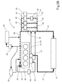
- FIG. 2A shows a first schematically illustrated engine cooling system 20.
- the engine cooling system 20 comprises a first coolant circuit 21 connecting a coolant outlet of an engine 30 to a radiator 31, a thermostat 32 arranged in the first coolant circuit 21, which thermostat 32 is arranged to be closed during engine warm-up, thereby preventing flow through the first coolant circuit, and a second coolant circuit 22 connecting the radiator to a coolant inlet of the engine 30.
- a coolant pump 33 is provided for circulating coolant through the cooling system 20.
- the coolant pump 33 is arranged in the second coolant circuit 22 and is driven directly by the engine 30, for instance, electric or hydraulic means (not shown).
- the terms "circuit” and "coolant circuit” are used to describe suitable means for conveying coolant through an engine or a powertrain cooling system.
- the cooling system further comprises a bypass circuit 24 connecting the thermostat to the second coolant circuit 22 upstream of a first throttle valve 34.
- the thermostat 32 is closed during an engine warm-up mode, i.e. when starting a cold engine, wherein the coolant flow supplied by the coolant pump 33 flows through the bypass circuit 24. This will prevent cooling of the coolant in the radiator 31 during the engine warm-up mode.
- the coolant temperature will immediately begin to increase as the coolant flowing through the engine 30 is heated by the heat generated in the combustion chambers.
- the thermostat 32 is a low temperature thermostat that will open at a relatively lower temperature. In a conventional cooling system the thermostat will open at approximately 90 °C, whereby the coolant flow will pass from the engine and directly into a main coolant circuit to be cooled in the radiator. In this case, the low temperature thermostat 32 opens at a temperature of 75-80 °C.
- the cooling system 20 further comprises a number of parallel circuits 25, 26, 27, 2n, each comprising a throttle valve 35, 36, 37, 3n and a heat exchanger 45, 46, 47, 4n, respectively.
- Each parallel circuit 25, 26, 27, 2n is connected to the second coolant circuit 22 at a common location upstream of the bypass circuit 24 and downstream of the first throttle valve 34. While the thermostat is closed, a partial coolant flow is directed from the bypass circuit 24 and upstream through the second coolant circuit 22 into the parallel circuits 25, 26, 27, 2n during engine warm-up.
- the throttle valve 34 in the secondary circuit 22 will restrict the coolant flow from the bypass circuit 24 and force a part of the coolant flow through the parallel circuits 25, 26, 27, 2n.
- This arrangement causes a reverse flow over a portion of the second coolant circuit 22, between the connection with the bypass circuit 24 and the connection of the parallel circuits 25, 26, 27, 2n.
- This counter flow prevents cold coolant in the second coolant circuit 22 in or downstream of the radiator 31 and upstream of the parallel circuits 25, 26, 27, 2n from being drawn towards the coolant pump 33 and the engine 30.
- the coolant flow in the second coolant circuit 22 and the parallel circuits 25, 26, 27 during engine warm-up is indicated with dashed lines in the respective circuit.
- the coolant flowing through the parallel circuits 25, 26, 27, 2n is returned to the second coolant circuit 22 downstream of the first throttle valve 34.
- Each parallel circuit 25, 26, 27, 2n is provided with a heat exchanger 45, 46, 47, 4n that is arranged for selectively heating or cooling a powertrain component (not shown).
- a first parallel circuit 25 comprises an exhaust gas recirculation EGR heat exchanger 45.
- a second parallel circuit 26 comprises a catalytic converter heat exchanger 46 for heating e.g. a selective catalytic reduction (SCR) device.
- a third parallel circuit 27 comprises a transmission oil heat exchanger 47.
- the parallel circuit 27 comprising the transmission oil heat exchanger 47 also comprises a controllable valve 38.
- This valve 38 is open while the thermostat 32 is closed, in order to assist in heating the transmission, and is closed when the thermostat 32 opens, in order to stop cold coolant from the radiator 31 to cool the transmission unnecessarily.
- a cooling system 20 according to the invention can comprise further parallel circuits 2n comprising a throttle valve 3n and a heat exchanger 4n, as indicated by dashed lines in Figure 2A .
- the cooling system 20 further comprises a third coolant circuit 23 connecting the coolant pump 33 to an engine oil heat exchanger 39, often termed oil cooler.
- a fourth coolant circuit 28 is provided for connecting the engine oil cooler 39 to the second coolant circuit 22 upstream of the first throttle valve 34 and downstream of the parallel circuits 25, 26, 27, as shown.
- the fourth coolant circuit 28 can be connected upstream of the bypass circuit 24 and downstream of the parallel circuits 25, 26, 27.
- the third coolant circuit 23 comprises a controllable valve 40. This controllable valve 40 is open while the thermostat 32 is closed, in order to assist in heating the engine oil, and is closed when the thermostat 32 opens, in order to increase the oil temperature towards a desired operating temperature.
- DOC diesel oxidation catalyst
- CO carbon monoxide
- HC gas phase hydrocarbons
- SOF organic fraction of diesel particulates
- each parallel circuit is provided with a heat exchanger and a throttle valve.
- all throttle valves are shown as fixed flow valves pre-set to balance the coolant flow through the first throttle valve 34 and through each parallel circuit 25, 26, 27.
- the flow rate is determined by the heating and cooling requirements for each respective component connected to a respective heat exchanger 45, 46, 47 in a parallel circuit.
- At least one throttle valve is a controllable flow valve arranged to balance the coolant flow through the first throttle valve and the at least one parallel circuit.
- the first throttle valve in the second coolant circuit and/or each throttle valve in a parallel circuit can be adjusted in steps or continuously to adapt the flow rate for the first throttle valve and each individual heat exchanger dependent on the current heating or cooling requirements for each respective component connected to a heat exchanger.
- the cooling system 20 shown in Figure 2A further comprises a heater 51 for the passenger compartment. Coolant can be directed from the engine 30, through a controllable valve 52 to the heater 51, before being returned to the second coolant circuit 22 upstream of the coolant pump 33 and downstream of the first throttle valve 34. A portion of the coolant drawn from the engine 30 towards the heater 51 can be passed through a de-gassing unit 53 and be returned to the second coolant circuit 22 upstream of the coolant pump 33 and downstream of the return flow from the heater 51.
- Figure 2B shows an alternative version of the engine cooling system in Figure 2A .
- the engine cooling system in Figure 2B substantially identical to the example described in Figure 2A and uses the same reference numerals for corresponding components.
- the cooling system 20 in Figure 2B comprises a number of parallel circuits 25, 26, 27, 2n, each comprising a heat exchanger 45, 46, 47, 4n, respectively, arranged for selectively heating or cooling a powertrain component (not shown).
- Each parallel circuit 25, 26, 27, 2n is connected to the second coolant circuit 22 at a common location upstream of the bypass circuit 24 and downstream of the first throttle valve 34. While the thermostat is closed, a partial coolant flow is directed from the bypass circuit 24 and upstream through the second coolant circuit 22 into the parallel circuits 25, 26, 27, 2n during engine warm-up.
- the throttle valve 34 in the secondary circuit 22 will restrict the coolant flow from the bypass circuit 24 and force a part of the coolant flow through the parallel circuits 25, 26, 27, 2n.
- This arrangement causes a reverse flow over a portion of the second coolant circuit 22, between the connection with the bypass circuit 24 and the connection of the parallel circuits 25, 26, 27, 2n.
- This counter flow prevents cold coolant in the second coolant circuit 22 in or downstream of the radiator 31 and upstream of the parallel circuits 25, 26, 27, 2n from being drawn towards the coolant pump 33 and the engine 30.
- the coolant flow in the second coolant circuit 22 and the parallel circuits 25, 26, 27 during engine warm-up is indicated with dashed lines in the respective circuit.
- each parallel circuit is provided with a heat exchanger without an associated throttle valve (see Fig.2A ; "35, 36, 37, 3n").
- the dimensions of each parallel circuit 25, 26, 27 is selected to balance the coolant flow through the second coolant circuit 22 upstream of the bypass circuit and the parallel circuits 25, 26, 27.
- FIG 3 shows a schematically illustrated first alternative example of an engine cooling system according to the invention.
- the engine cooling system in Figure 3 substantially identical to the example described in Figure 2A and uses the same reference numerals for corresponding components.
- the first alternative example differs from the engine cooling system described in Figure 2A in that it further comprises a second coolant pump 60 arranged to control the coolant flow through the at least one parallel circuit 25, 26, 27.
- the second coolant pump 60 is a controllable pump located in the inlet of the at least one parallel circuit 25, 26, 27 adjacent the connection of the parallel circuit 25, 26, 27 to the second coolant circuit 22. In this way the flow rate through each parallel circuit 25, 26, 27 is controllable by a throttle valve 35, 36, 37 in the respective parallel circuit and by controlling the second coolant pump 60.
- the provision of a coolant pump for the at least one parallel circuit makes the first throttle valve 34 (indicated in dashed lines) in the second coolant circuit 22 optional.
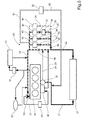
- FIG 4 shows a schematically illustrated second alternative example of an engine cooling system according to the invention.
- the engine cooling system in Figure 4 substantially identical to the example described in Figure 3 and uses the same reference numerals for corresponding components.
- the second alternative example differs from the engine cooling system described in Figure 3 in that it further comprises a controllable thermostat 42 in the first coolant circuit 21 connecting the coolant outlet of the engine to the radiator 31.
- the thermostat 42 is be partially opened to provide a leakage flow through the radiator 31. This will provide the EGR heat exchanger 45 with cold coolant from the relatively cold portion of the coolant circuit comprising the first coolant circuit 21, the radiator 31 and the portion of the second coolant circuit 22 upstream of the parallel circuits 25, 26, 27.
- the controllable thermostat 42 will subsequently be gradually opened as the coolant temperature increases, until it is fully open at its predetermined set temperature. The set temperature of the thermostat can later be adjusted up or down dependent on current cooling requirements.
- This second example is preferably, but not necessarily, combined with a second coolant pump 42 as described in the first alternative example in Figure 3 .
- the provision of a second coolant pump 42 allows the flow rate through the EGR heat exchanger 45 to be controlled accurately.
- FIG. 5 shows a schematically illustrated third alternative example of an engine cooling system according to the invention.
- the engine cooling system in Figure 5 substantially identical to the example described in Figure 3 and uses the same reference numerals for corresponding components.
- the third alternative example differs from the engine cooling system described in Figure 3 in that it further comprises a an alternative coolant return circuit 51, 52, 53.
- the alternative coolant return circuit 51, 52, 53 comprises a first return circuit 51 connected to the parallel circuits 25, 26, 27 downstream of the respective heat exchanger 45, 46, 47, a controllable valve 52, and a second return circuit 52 connected to the first coolant circuit 21 downstream of the thermostat 32 and upstream of the radiator 31.
- the coolant return circuit 51, 52, 53 bypasses the second coolant circuit 22 and the coolant pump 33 and returns a partial coolant flow from the parallel circuits 25, 26, 27 to the first coolant circuit 21.
- the controllable valve 52 can be opened prior to the opening of the thermostat to provide a leakage flow through the radiator 31 towards the parallel circuits 25, 26, 27.
- the valve 52 can be either a fixed flow valve or a controllable flow valve. This will provide the EGR heat exchanger 45 with cold coolant from the relatively cold portion of the coolant circuit comprising the first coolant circuit 21, the radiator 31 and the portion of the second coolant circuit 22 upstream of the parallel circuits 25, 26, 27.. In this way the NOx-emissions from the engine exhaust can be reduced when the engine 30 approaches its normal operating temperature.
- This third example shown in Figure 5 provides an alternative to the second alternative example shown in Figure 4 , wherein the alternative coolant return circuit 51, 52, 53 replaces a controllable thermostat 42.
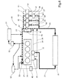
- FIG. 6 shows a schematically illustrated third alternative example of an engine cooling system according to the invention.
- the engine cooling system in Figure 6 substantially identical to the example described in Figure 2A and uses the same reference numerals for corresponding components.
- the third alternative example differs from the engine cooling system described in Figure 2A in that it comprises an alternative flow controlling device 61, 62, 63, replacing the first throttle valve 34 in the second coolant circuit 22 downstream of the bypass circuit 24.
- the alternative flow controlling device 61, 62, 63 comprises a controllable valve 61 with a reduced flow bypass circuit 62.
- the flow restriction function can be achieved either by the use of a throttle valve 63 (shown in dashed lines) or by a conduit having a reduced cross-sectional area suitable for reducing the flow rate in the bypass circuit 62.
- the valve can be opened to allow full flow of coolant through the second coolant circuit 22.
- This fourth example can be combined with a second coolant pump 60 (shown in dashed lines) as described in the first alternative example shown in Figure 3 .
- the provision of a second coolant pump 60 allows at least a minimum flow rate through at least the EGR heat exchanger 45 to be maintained even if the valve 61 in the second coolant circuit 22 is fully open.
Landscapes
- Engineering & Computer Science (AREA)
- Chemical & Material Sciences (AREA)
- Combustion & Propulsion (AREA)
- Mechanical Engineering (AREA)
- General Engineering & Computer Science (AREA)
- Exhaust-Gas Circulating Devices (AREA)
- Combined Controls Of Internal Combustion Engines (AREA)
Priority Applications (3)
| Application Number | Priority Date | Filing Date | Title |
|---|---|---|---|
| EP14185243.4A EP2998536B1 (fr) | 2014-09-18 | 2014-09-18 | Agencement et procédé de commande d'un système de refroidissement de moteur |
| US14/847,547 US9797295B2 (en) | 2014-09-18 | 2015-09-08 | Arrangement and a control method of an engine cooling system |
| CN201510575343.5A CN105604675B (zh) | 2014-09-18 | 2015-09-10 | 发动机冷却系统的配置和控制方法 |
Applications Claiming Priority (1)
| Application Number | Priority Date | Filing Date | Title |
|---|---|---|---|
| EP14185243.4A EP2998536B1 (fr) | 2014-09-18 | 2014-09-18 | Agencement et procédé de commande d'un système de refroidissement de moteur |
Publications (2)
| Publication Number | Publication Date |
|---|---|
| EP2998536A1 true EP2998536A1 (fr) | 2016-03-23 |
| EP2998536B1 EP2998536B1 (fr) | 2020-03-04 |
Family
ID=51570321
Family Applications (1)
| Application Number | Title | Priority Date | Filing Date |
|---|---|---|---|
| EP14185243.4A Active EP2998536B1 (fr) | 2014-09-18 | 2014-09-18 | Agencement et procédé de commande d'un système de refroidissement de moteur |
Country Status (3)
| Country | Link |
|---|---|
| US (1) | US9797295B2 (fr) |
| EP (1) | EP2998536B1 (fr) |
| CN (1) | CN105604675B (fr) |
Families Citing this family (8)
| Publication number | Priority date | Publication date | Assignee | Title |
|---|---|---|---|---|
| WO2014098656A1 (fr) * | 2012-12-21 | 2014-06-26 | Volvo Truck Corporation | Système de refroidissement destiné à un véhicule hybride à alimentation mécanique et hydraulique |
| US10300786B2 (en) | 2014-12-19 | 2019-05-28 | Polaris Industries Inc. | Utility vehicle |
| JP2017067015A (ja) * | 2015-09-30 | 2017-04-06 | アイシン精機株式会社 | 冷却制御装置 |
| CN106194389B (zh) * | 2016-08-31 | 2019-04-05 | 江苏云瀚股份有限公司 | 一种发动机冷却液的恒温控制装置及其控制方法 |
| DE102016218020A1 (de) * | 2016-09-20 | 2018-04-05 | Robert Bosch Gmbh | Kühlkreis und Verfahren zum Betreiben eines Kühlkreises |
| CN111691966A (zh) * | 2020-06-16 | 2020-09-22 | 安徽江淮汽车集团股份有限公司 | 一种发动机冷却系统 |
| CA3156559A1 (fr) * | 2021-05-05 | 2022-11-05 | Polaris Industries Inc. | Mecanisme d'echappement pour vehicule utilitaire |
| DE102021206117A1 (de) * | 2021-06-16 | 2022-12-22 | Zf Friedrichshafen Ag | Traktionsantrieb mit einem Kühlsystem mit zwei Kühlkreisen |
Citations (4)
| Publication number | Priority date | Publication date | Assignee | Title |
|---|---|---|---|---|
| EP0499071A1 (fr) * | 1991-02-11 | 1992-08-19 | Behr GmbH & Co. | Système de refroidissement pour un moteur à combustion interne d'un véhicule |
| EP1995424A2 (fr) * | 2007-05-07 | 2008-11-26 | Nissan Motor Co., Ltd. | Système de refroidissement de moteur à combustion interne |
| DE102012205001A1 (de) * | 2012-02-21 | 2013-08-22 | Bayerische Motoren Werke Aktiengesellschaft | Kühlmittelkreislauf für eine Brennkraftmaschine und Verfahren zum Betrieb der Brennkraftmaschine |
| WO2014102122A1 (fr) * | 2012-12-24 | 2014-07-03 | Valtra Oy Ab | Moyen de refroidissement auxiliaire pour un module de dosage dans un système de traitement de gaz d'échappement |
Family Cites Families (10)
| Publication number | Priority date | Publication date | Assignee | Title |
|---|---|---|---|---|
| BR9501795A (pt) * | 1994-04-27 | 1995-12-12 | Schatz Thermo System Gmbh | Método e conjunto para operação de amazenadores de calor sensível |
| FR2816004B1 (fr) * | 2000-10-27 | 2003-06-20 | Mark Iv Systemes Moteurs Sa | Ensemble de refroidissement pour vehicules a moteur |
| DE10134678A1 (de) * | 2001-07-20 | 2003-02-06 | Bosch Gmbh Robert | Vorrichtung zum Kühlen und Heizen eines Kraftfahrzeuges |
| DE10141389B4 (de) * | 2001-08-20 | 2005-09-22 | Visteon Global Technologies, Inc., Dearborn | Kombinationswärmeübertrager für den Kühlmittelkreislauf eines Kraftfahrzeuges |
| US6993923B2 (en) * | 2001-10-05 | 2006-02-07 | Rich Beers Marine, Inc. | Load bank |
| SE530441C2 (sv) * | 2006-10-18 | 2008-06-10 | Volvo Lastvagnar Ab | Motorkylsystem |
| JP4456162B2 (ja) * | 2008-04-11 | 2010-04-28 | 株式会社山田製作所 | エンジンの冷却装置 |
| SE532729C2 (sv) * | 2008-08-22 | 2010-03-23 | Scania Cv Ab | Kylsystem hos ett fordon som drivs av en förbränningsmotor |
| SE535316C2 (sv) * | 2011-02-25 | 2012-06-26 | Scania Cv Ab | System för att omvandla värmeenergi till mekanisk energi i ett fordon |
| US9500115B2 (en) * | 2013-03-01 | 2016-11-22 | Ford Global Technologies, Llc | Method and system for an internal combustion engine with liquid-cooled cylinder head and liquid-cooled cylinder block |
-
2014
- 2014-09-18 EP EP14185243.4A patent/EP2998536B1/fr active Active
-
2015
- 2015-09-08 US US14/847,547 patent/US9797295B2/en active Active
- 2015-09-10 CN CN201510575343.5A patent/CN105604675B/zh active Active
Patent Citations (4)
| Publication number | Priority date | Publication date | Assignee | Title |
|---|---|---|---|---|
| EP0499071A1 (fr) * | 1991-02-11 | 1992-08-19 | Behr GmbH & Co. | Système de refroidissement pour un moteur à combustion interne d'un véhicule |
| EP1995424A2 (fr) * | 2007-05-07 | 2008-11-26 | Nissan Motor Co., Ltd. | Système de refroidissement de moteur à combustion interne |
| DE102012205001A1 (de) * | 2012-02-21 | 2013-08-22 | Bayerische Motoren Werke Aktiengesellschaft | Kühlmittelkreislauf für eine Brennkraftmaschine und Verfahren zum Betrieb der Brennkraftmaschine |
| WO2014102122A1 (fr) * | 2012-12-24 | 2014-07-03 | Valtra Oy Ab | Moyen de refroidissement auxiliaire pour un module de dosage dans un système de traitement de gaz d'échappement |
Also Published As
| Publication number | Publication date |
|---|---|
| US9797295B2 (en) | 2017-10-24 |
| US20160084146A1 (en) | 2016-03-24 |
| CN105604675A (zh) | 2016-05-25 |
| CN105604675B (zh) | 2019-06-04 |
| EP2998536B1 (fr) | 2020-03-04 |
Similar Documents
| Publication | Publication Date | Title |
|---|---|---|
| US9797295B2 (en) | Arrangement and a control method of an engine cooling system | |
| US8205443B2 (en) | Heat exchanging systems for motor vehicles | |
| US9567892B2 (en) | Cooling system for an internal combustion engine | |
| US9188050B2 (en) | Engine cooling system | |
| RU2678926C2 (ru) | Способ (варианты) охлаждения двигателя транспортного средства и система обогрева салона транспортного средства | |
| US9097174B2 (en) | System and method for conditioning intake air to an internal combustion engine | |
| RU2580981C2 (ru) | Система охлаждения двигателя внутреннего сгорания с наддувом | |
| JP5993759B2 (ja) | エンジンの吸気冷却装置 | |
| US8828342B1 (en) | DPF energy conservation | |
| US20080149080A1 (en) | Internal combustion engine and method for operating an internal combustion engine | |
| RU2716934C2 (ru) | Способ для двигателя (варианты) и система двигателя | |
| RU2016152392A (ru) | Способ и система для рекуперации тепла отработавших газов | |
| KR20080099151A (ko) | 내연 기관의 냉각계 장치 | |
| US20160348620A1 (en) | Assembly including a heat engine and an electric compressor configured to heat the air-fuel mixture | |
| RU2689277C2 (ru) | Способ и система для рециркуляции отработавших газов и рекуперации их тепла | |
| GB2472228A (en) | Reducing the fuel consumption of an i.c. engine by using heat from an EGR cooler to heat engine oil after cold-starting | |
| CN114320537A (zh) | 内燃发动机系统 | |
| JP2011047305A (ja) | 内燃機関 | |
| US10823040B2 (en) | Exhaust gas control system for internal combustion engine | |
| US20140047817A1 (en) | Ducting system for feeding air and exhaust gases to an internal combustion engine and for discharging the exhaust gases produced by the internal combustion engine from the internal combustion engine | |
| JP2013113182A (ja) | エンジンの冷却装置及びその冷却方法 | |
| US20080257526A1 (en) | Device for Thermal Control of Recirculated Gases in an Internal Combustion Engine | |
| US10465635B2 (en) | Systems and methods with improved LR-EGR activation | |
| JP2012082723A (ja) | 内燃機関の冷却装置 | |
| JP6183170B2 (ja) | エンジンの除熱量制御システム |
Legal Events
| Date | Code | Title | Description |
|---|---|---|---|
| PUAI | Public reference made under article 153(3) epc to a published international application that has entered the european phase |
Free format text: ORIGINAL CODE: 0009012 |
|
| AK | Designated contracting states |
Kind code of ref document: A1 Designated state(s): AL AT BE BG CH CY CZ DE DK EE ES FI FR GB GR HR HU IE IS IT LI LT LU LV MC MK MT NL NO PL PT RO RS SE SI SK SM TR |
|
| AX | Request for extension of the european patent |
Extension state: BA ME |
|
| 17P | Request for examination filed |
Effective date: 20160923 |
|
| RBV | Designated contracting states (corrected) |
Designated state(s): AL AT BE BG CH CY CZ DE DK EE ES FI FR GB GR HR HU IE IS IT LI LT LU LV MC MK MT NL NO PL PT RO RS SE SI SK SM TR |
|
| STAA | Information on the status of an ep patent application or granted ep patent |
Free format text: STATUS: EXAMINATION IS IN PROGRESS |
|
| 17Q | First examination report despatched |
Effective date: 20190129 |
|
| GRAP | Despatch of communication of intention to grant a patent |
Free format text: ORIGINAL CODE: EPIDOSNIGR1 |
|
| STAA | Information on the status of an ep patent application or granted ep patent |
Free format text: STATUS: GRANT OF PATENT IS INTENDED |
|
| RIC1 | Information provided on ipc code assigned before grant |
Ipc: F01P 11/04 20060101ALI20190523BHEP Ipc: F01P 7/14 20060101ALN20190523BHEP Ipc: F01P 5/10 20060101ALN20190523BHEP Ipc: F01P 7/16 20060101AFI20190523BHEP |
|
| INTG | Intention to grant announced |
Effective date: 20190607 |
|
| GRAJ | Information related to disapproval of communication of intention to grant by the applicant or resumption of examination proceedings by the epo deleted |
Free format text: ORIGINAL CODE: EPIDOSDIGR1 |
|
| STAA | Information on the status of an ep patent application or granted ep patent |
Free format text: STATUS: EXAMINATION IS IN PROGRESS |
|
| INTC | Intention to grant announced (deleted) | ||
| GRAJ | Information related to disapproval of communication of intention to grant by the applicant or resumption of examination proceedings by the epo deleted |
Free format text: ORIGINAL CODE: EPIDOSDIGR1 |
|
| STAA | Information on the status of an ep patent application or granted ep patent |
Free format text: STATUS: GRANT OF PATENT IS INTENDED |
|
| GRAP | Despatch of communication of intention to grant a patent |
Free format text: ORIGINAL CODE: EPIDOSNIGR1 |
|
| RIC1 | Information provided on ipc code assigned before grant |
Ipc: F01P 7/14 20060101ALN20190909BHEP Ipc: F01P 5/10 20060101ALN20190909BHEP Ipc: F01P 7/16 20060101AFI20190909BHEP Ipc: F01P 11/04 20060101ALI20190909BHEP |
|
| INTG | Intention to grant announced |
Effective date: 20190927 |
|
| GRAS | Grant fee paid |
Free format text: ORIGINAL CODE: EPIDOSNIGR3 |
|
| GRAA | (expected) grant |
Free format text: ORIGINAL CODE: 0009210 |
|
| STAA | Information on the status of an ep patent application or granted ep patent |
Free format text: STATUS: THE PATENT HAS BEEN GRANTED |
|
| AK | Designated contracting states |
Kind code of ref document: B1 Designated state(s): AL AT BE BG CH CY CZ DE DK EE ES FI FR GB GR HR HU IE IS IT LI LT LU LV MC MK MT NL NO PL PT RO RS SE SI SK SM TR |
|
| REG | Reference to a national code |
Ref country code: GB Ref legal event code: FG4D |
|
| REG | Reference to a national code |
Ref country code: CH Ref legal event code: EP |
|
| REG | Reference to a national code |
Ref country code: AT Ref legal event code: REF Ref document number: 1240620 Country of ref document: AT Kind code of ref document: T Effective date: 20200315 |
|
| REG | Reference to a national code |
Ref country code: DE Ref legal event code: R096 Ref document number: 602014061783 Country of ref document: DE |
|
| REG | Reference to a national code |
Ref country code: IE Ref legal event code: FG4D |
|
| PG25 | Lapsed in a contracting state [announced via postgrant information from national office to epo] |
Ref country code: FI Free format text: LAPSE BECAUSE OF FAILURE TO SUBMIT A TRANSLATION OF THE DESCRIPTION OR TO PAY THE FEE WITHIN THE PRESCRIBED TIME-LIMIT Effective date: 20200304 Ref country code: NO Free format text: LAPSE BECAUSE OF FAILURE TO SUBMIT A TRANSLATION OF THE DESCRIPTION OR TO PAY THE FEE WITHIN THE PRESCRIBED TIME-LIMIT Effective date: 20200604 Ref country code: RS Free format text: LAPSE BECAUSE OF FAILURE TO SUBMIT A TRANSLATION OF THE DESCRIPTION OR TO PAY THE FEE WITHIN THE PRESCRIBED TIME-LIMIT Effective date: 20200304 |
|
| REG | Reference to a national code |
Ref country code: NL Ref legal event code: MP Effective date: 20200304 |
|
| PG25 | Lapsed in a contracting state [announced via postgrant information from national office to epo] |
Ref country code: HR Free format text: LAPSE BECAUSE OF FAILURE TO SUBMIT A TRANSLATION OF THE DESCRIPTION OR TO PAY THE FEE WITHIN THE PRESCRIBED TIME-LIMIT Effective date: 20200304 Ref country code: GR Free format text: LAPSE BECAUSE OF FAILURE TO SUBMIT A TRANSLATION OF THE DESCRIPTION OR TO PAY THE FEE WITHIN THE PRESCRIBED TIME-LIMIT Effective date: 20200605 Ref country code: LV Free format text: LAPSE BECAUSE OF FAILURE TO SUBMIT A TRANSLATION OF THE DESCRIPTION OR TO PAY THE FEE WITHIN THE PRESCRIBED TIME-LIMIT Effective date: 20200304 Ref country code: SE Free format text: LAPSE BECAUSE OF FAILURE TO SUBMIT A TRANSLATION OF THE DESCRIPTION OR TO PAY THE FEE WITHIN THE PRESCRIBED TIME-LIMIT Effective date: 20200304 Ref country code: BG Free format text: LAPSE BECAUSE OF FAILURE TO SUBMIT A TRANSLATION OF THE DESCRIPTION OR TO PAY THE FEE WITHIN THE PRESCRIBED TIME-LIMIT Effective date: 20200604 |
|
| REG | Reference to a national code |
Ref country code: LT Ref legal event code: MG4D |
|
| PG25 | Lapsed in a contracting state [announced via postgrant information from national office to epo] |
Ref country code: NL Free format text: LAPSE BECAUSE OF FAILURE TO SUBMIT A TRANSLATION OF THE DESCRIPTION OR TO PAY THE FEE WITHIN THE PRESCRIBED TIME-LIMIT Effective date: 20200304 |
|
| PG25 | Lapsed in a contracting state [announced via postgrant information from national office to epo] |
Ref country code: PT Free format text: LAPSE BECAUSE OF FAILURE TO SUBMIT A TRANSLATION OF THE DESCRIPTION OR TO PAY THE FEE WITHIN THE PRESCRIBED TIME-LIMIT Effective date: 20200729 Ref country code: ES Free format text: LAPSE BECAUSE OF FAILURE TO SUBMIT A TRANSLATION OF THE DESCRIPTION OR TO PAY THE FEE WITHIN THE PRESCRIBED TIME-LIMIT Effective date: 20200304 Ref country code: CZ Free format text: LAPSE BECAUSE OF FAILURE TO SUBMIT A TRANSLATION OF THE DESCRIPTION OR TO PAY THE FEE WITHIN THE PRESCRIBED TIME-LIMIT Effective date: 20200304 Ref country code: RO Free format text: LAPSE BECAUSE OF FAILURE TO SUBMIT A TRANSLATION OF THE DESCRIPTION OR TO PAY THE FEE WITHIN THE PRESCRIBED TIME-LIMIT Effective date: 20200304 Ref country code: LT Free format text: LAPSE BECAUSE OF FAILURE TO SUBMIT A TRANSLATION OF THE DESCRIPTION OR TO PAY THE FEE WITHIN THE PRESCRIBED TIME-LIMIT Effective date: 20200304 Ref country code: EE Free format text: LAPSE BECAUSE OF FAILURE TO SUBMIT A TRANSLATION OF THE DESCRIPTION OR TO PAY THE FEE WITHIN THE PRESCRIBED TIME-LIMIT Effective date: 20200304 Ref country code: SM Free format text: LAPSE BECAUSE OF FAILURE TO SUBMIT A TRANSLATION OF THE DESCRIPTION OR TO PAY THE FEE WITHIN THE PRESCRIBED TIME-LIMIT Effective date: 20200304 Ref country code: SK Free format text: LAPSE BECAUSE OF FAILURE TO SUBMIT A TRANSLATION OF THE DESCRIPTION OR TO PAY THE FEE WITHIN THE PRESCRIBED TIME-LIMIT Effective date: 20200304 Ref country code: IS Free format text: LAPSE BECAUSE OF FAILURE TO SUBMIT A TRANSLATION OF THE DESCRIPTION OR TO PAY THE FEE WITHIN THE PRESCRIBED TIME-LIMIT Effective date: 20200704 |
|
| REG | Reference to a national code |
Ref country code: AT Ref legal event code: MK05 Ref document number: 1240620 Country of ref document: AT Kind code of ref document: T Effective date: 20200304 |
|
| REG | Reference to a national code |
Ref country code: DE Ref legal event code: R097 Ref document number: 602014061783 Country of ref document: DE |
|
| PLBE | No opposition filed within time limit |
Free format text: ORIGINAL CODE: 0009261 |
|
| STAA | Information on the status of an ep patent application or granted ep patent |
Free format text: STATUS: NO OPPOSITION FILED WITHIN TIME LIMIT |
|
| PG25 | Lapsed in a contracting state [announced via postgrant information from national office to epo] |
Ref country code: DK Free format text: LAPSE BECAUSE OF FAILURE TO SUBMIT A TRANSLATION OF THE DESCRIPTION OR TO PAY THE FEE WITHIN THE PRESCRIBED TIME-LIMIT Effective date: 20200304 Ref country code: AT Free format text: LAPSE BECAUSE OF FAILURE TO SUBMIT A TRANSLATION OF THE DESCRIPTION OR TO PAY THE FEE WITHIN THE PRESCRIBED TIME-LIMIT Effective date: 20200304 |
|
| 26N | No opposition filed |
Effective date: 20201207 |
|
| PG25 | Lapsed in a contracting state [announced via postgrant information from national office to epo] |
Ref country code: PL Free format text: LAPSE BECAUSE OF FAILURE TO SUBMIT A TRANSLATION OF THE DESCRIPTION OR TO PAY THE FEE WITHIN THE PRESCRIBED TIME-LIMIT Effective date: 20200304 Ref country code: SI Free format text: LAPSE BECAUSE OF FAILURE TO SUBMIT A TRANSLATION OF THE DESCRIPTION OR TO PAY THE FEE WITHIN THE PRESCRIBED TIME-LIMIT Effective date: 20200304 |
|
| PG25 | Lapsed in a contracting state [announced via postgrant information from national office to epo] |
Ref country code: MC Free format text: LAPSE BECAUSE OF FAILURE TO SUBMIT A TRANSLATION OF THE DESCRIPTION OR TO PAY THE FEE WITHIN THE PRESCRIBED TIME-LIMIT Effective date: 20200304 |
|
| REG | Reference to a national code |
Ref country code: CH Ref legal event code: PL |
|
| GBPC | Gb: european patent ceased through non-payment of renewal fee |
Effective date: 20200918 |
|
| REG | Reference to a national code |
Ref country code: BE Ref legal event code: MM Effective date: 20200930 |
|
| PG25 | Lapsed in a contracting state [announced via postgrant information from national office to epo] |
Ref country code: LU Free format text: LAPSE BECAUSE OF NON-PAYMENT OF DUE FEES Effective date: 20200918 |
|
| PG25 | Lapsed in a contracting state [announced via postgrant information from national office to epo] |
Ref country code: GB Free format text: LAPSE BECAUSE OF NON-PAYMENT OF DUE FEES Effective date: 20200918 Ref country code: LI Free format text: LAPSE BECAUSE OF NON-PAYMENT OF DUE FEES Effective date: 20200930 Ref country code: IE Free format text: LAPSE BECAUSE OF NON-PAYMENT OF DUE FEES Effective date: 20200918 Ref country code: CH Free format text: LAPSE BECAUSE OF NON-PAYMENT OF DUE FEES Effective date: 20200930 Ref country code: BE Free format text: LAPSE BECAUSE OF NON-PAYMENT OF DUE FEES Effective date: 20200930 |
|
| PG25 | Lapsed in a contracting state [announced via postgrant information from national office to epo] |
Ref country code: TR Free format text: LAPSE BECAUSE OF FAILURE TO SUBMIT A TRANSLATION OF THE DESCRIPTION OR TO PAY THE FEE WITHIN THE PRESCRIBED TIME-LIMIT Effective date: 20200304 Ref country code: MT Free format text: LAPSE BECAUSE OF FAILURE TO SUBMIT A TRANSLATION OF THE DESCRIPTION OR TO PAY THE FEE WITHIN THE PRESCRIBED TIME-LIMIT Effective date: 20200304 Ref country code: CY Free format text: LAPSE BECAUSE OF FAILURE TO SUBMIT A TRANSLATION OF THE DESCRIPTION OR TO PAY THE FEE WITHIN THE PRESCRIBED TIME-LIMIT Effective date: 20200304 |
|
| PG25 | Lapsed in a contracting state [announced via postgrant information from national office to epo] |
Ref country code: MK Free format text: LAPSE BECAUSE OF FAILURE TO SUBMIT A TRANSLATION OF THE DESCRIPTION OR TO PAY THE FEE WITHIN THE PRESCRIBED TIME-LIMIT Effective date: 20200304 Ref country code: AL Free format text: LAPSE BECAUSE OF FAILURE TO SUBMIT A TRANSLATION OF THE DESCRIPTION OR TO PAY THE FEE WITHIN THE PRESCRIBED TIME-LIMIT Effective date: 20200304 |
|
| PGFP | Annual fee paid to national office [announced via postgrant information from national office to epo] |
Ref country code: IT Payment date: 20230822 Year of fee payment: 10 |
|
| PGFP | Annual fee paid to national office [announced via postgrant information from national office to epo] |
Ref country code: FR Payment date: 20230822 Year of fee payment: 10 Ref country code: DE Payment date: 20230822 Year of fee payment: 10 |
|
| P01 | Opt-out of the competence of the unified patent court (upc) registered |
Effective date: 20231212 |