EP2998501B1 - A telescopic ladder assembly - Google Patents
A telescopic ladder assembly Download PDFInfo
- Publication number
- EP2998501B1 EP2998501B1 EP15188391.5A EP15188391A EP2998501B1 EP 2998501 B1 EP2998501 B1 EP 2998501B1 EP 15188391 A EP15188391 A EP 15188391A EP 2998501 B1 EP2998501 B1 EP 2998501B1
- Authority
- EP
- European Patent Office
- Prior art keywords
- ladder
- rung
- actuators
- assembly according
- ladder assembly
- Prior art date
- Legal status (The legal status is an assumption and is not a legal conclusion. Google has not performed a legal analysis and makes no representation as to the accuracy of the status listed.)
- Active
Links
- 230000007246 mechanism Effects 0.000 claims description 14
- XAGFODPZIPBFFR-UHFFFAOYSA-N aluminium Chemical compound [Al] XAGFODPZIPBFFR-UHFFFAOYSA-N 0.000 claims description 3
- 229910052782 aluminium Inorganic materials 0.000 claims description 3
- 239000004411 aluminium Substances 0.000 claims description 3
- 230000000295 complement effect Effects 0.000 claims description 3
- 230000008878 coupling Effects 0.000 claims description 3
- 238000010168 coupling process Methods 0.000 claims description 3
- 238000005859 coupling reaction Methods 0.000 claims description 3
- 239000000463 material Substances 0.000 claims description 3
- 239000004033 plastic Substances 0.000 claims description 3
- 229920003023 plastic Polymers 0.000 claims description 3
- 230000000712 assembly Effects 0.000 description 3
- 238000000429 assembly Methods 0.000 description 3
- 230000009194 climbing Effects 0.000 description 3
- 238000009826 distribution Methods 0.000 description 2
- 230000000694 effects Effects 0.000 description 2
- 210000004247 hand Anatomy 0.000 description 2
- 239000011796 hollow space material Substances 0.000 description 2
- 230000033001 locomotion Effects 0.000 description 2
- 238000004519 manufacturing process Methods 0.000 description 2
- 238000003860 storage Methods 0.000 description 2
- 229920002430 Fibre-reinforced plastic Polymers 0.000 description 1
- 230000004308 accommodation Effects 0.000 description 1
- 230000008901 benefit Effects 0.000 description 1
- 238000010276 construction Methods 0.000 description 1
- 239000011151 fibre-reinforced plastic Substances 0.000 description 1
- 210000003811 finger Anatomy 0.000 description 1
- 238000001746 injection moulding Methods 0.000 description 1
- 238000000034 method Methods 0.000 description 1
- 230000008569 process Effects 0.000 description 1
- 239000000243 solution Substances 0.000 description 1
- 210000003813 thumb Anatomy 0.000 description 1
Images


Classifications
-
- E—FIXED CONSTRUCTIONS
- E06—DOORS, WINDOWS, SHUTTERS, OR ROLLER BLINDS IN GENERAL; LADDERS
- E06C—LADDERS
- E06C1/00—Ladders in general
- E06C1/02—Ladders in general with rigid longitudinal member or members
- E06C1/04—Ladders for resting against objects, e.g. walls poles, trees
- E06C1/08—Ladders for resting against objects, e.g. walls poles, trees multi-part
- E06C1/12—Ladders for resting against objects, e.g. walls poles, trees multi-part extensible, e.g. telescopic
- E06C1/125—Ladders for resting against objects, e.g. walls poles, trees multi-part extensible, e.g. telescopic with tubular longitudinal members nested within each other
-
- E—FIXED CONSTRUCTIONS
- E06—DOORS, WINDOWS, SHUTTERS, OR ROLLER BLINDS IN GENERAL; LADDERS
- E06C—LADDERS
- E06C7/00—Component parts, supporting parts, or accessories
- E06C7/08—Special construction of longitudinal members, or rungs or other treads
- E06C7/082—Connections between rungs or treads and longitudinal members
- E06C7/086—Connections between rungs or treads and longitudinal members with a connecting piece inserted in a hollow rung
Definitions
- the present invention relates to a telescopically extendable and collapsible ladder assembly having at least three ladder sections, each of said ladder sections having two tubular stile members arranged parallel to each other and interconnected at one end by a ladder rung to form a U-shaped ladder section; the stile members of each ladder section being telescopically inserted into the stile members of an adjacent ladder section.
- the ladder assembly further comprises automatic latch mechanisms for locking the telescopically inserted stile members relative to one another when the ladder sections are extended, the latch mechanisms being associated with one or more actuators for unlocking the stile members in order to allow for collapsing of the ladder assembly.
- ladder assemblies have become quite popular as portable ladders, such as a straight telescopic ladder or a step ladder, but also for stationary mounting, such as a loft ladder providing access to a loft.
- the present invention aims to propose measures that allow for improvements. These measures can either be applied alone or in combination. In a most preferred embodiment of the invention all measures are applied in a ladder assembly to obtain an optimum result.
- the present invention relates to a ladder assembly according to the preamble of claim 1.
- each ladder section includes a connector at each end of a rung, the connector having a rung portion connected to the end of the rung and having a front and a rear collar segment, each integral at one end thereof with the rung portion, the two collar segments substantially encircling the stile member, the collar segments having spaced apart opposed ends, a fastener assembly being provided bridging the opposed ends of the collar segments for rigidly coupling the collar segments around the stile member.
- the opposed ends lie along the longitudinal axis of the rung.
- the ends have a lateral protruding boss to accommodate the bolt and nut which pull the ends towards one another in order to fix the collar around the stile member.
- This lateral protruding boss is awkward, in particular in view of storage of the ladder, e.g. in a small cabinet or in a van.
- WO2007/079379 a different design of connector is shown which has two pieces.
- the one piece is connected to the rung and includes a half of the collar.
- the other piece is a collar half, that is fastened by two bolts on the other piece.
- the dividing plane (where the ends of the collar halves meet) lies at right angles to the longitudinal axis of the rung.
- This solution is complex and unsatisfactory as two bolts are used to clamp the collar on the stile member.
- the invention aims to provide a telescopic ladder assembly according to the preamble of claim 1, having an improved design with respect to ladder manufacturing and handling of the ladder.
- a ladder assembly according to the preamble of claim 1, which is characterized in that the first collar segment extends over an angle of between 120 and 150 degrees, more preferably between 130 and 140 degrees, with respect to the longitudinal axis of the rung, whereas the second collar segment extends over a complementary angle. It has been found that this position of the "split" of the collar has the effect of effective clamping of the collar onto the style.
- the outer face of the collar segments at the opposed ends thereof form a substantially triangular protrusion with respect to adjacent portions of the outer face of the collar segments. It is noted that this design can be used advantageously for the telescopic ladders wherein the actuators are located in close proximity to the stile member.
- first collar segment is the front collar segment and the second collar segment is the rear collar segment.
- a telescopic ladder assembly e.g. a straight ladder
- has automatic latch mechanisms e.g. at each end of a rung
- one or more associated manually operable actuators for unlocking the stile members in order to allow for collapsing of the ladder assembly, wherein these one or more actuators are arranged centrally on a ladder rung (preferably on the front) and are operable simultaneously with a single hand of the user. It has been found that a damper allows to obtain a very controlled motion of the ladder section upon collapse of the ladder.
- the user can now operate the one or more actuators simultaneously with one hand and use - at the same time - his other hand to guide the descending ladder section and/or stabilize the ladder during this operation. This allows for safe and gentle handling of the ladder during collapse, and avoids fast motions and undesirable impacts of the descending ladder sections as can be observed in known telescopic ladders.
- EP 1 402 143 it is disclosed to mount the actuators at the front of the rung and in close proximity to the stile members so that each actuator is manually and individually operable by a user holding his hands around the stile members, in particular around the connectors at the upper end of the stile members.
- This prior art design thus requires the user to hold both his hands around the ladder stiles during the collapse of the ladder. It is alleged that this design increases safety for the user with regard of a user's hand being seized between two rungs upon collapse of a ladder. Whilst that may be correct from said perspective, this arrangement does not take into account the fact that in many situations the user also needs to stabilize the ladder so it does not sway or hit against something during the collapse.
- the actuators are arranged centrally on the front side of the rung so as to be operable simultaneously with a single hand, wherein the front wall of the rung has an elongated recessed portion over the length thereof and the actuators are arranged in said recessed portion, each actuator having a rear extension, extending through a slot in said front wall into the interior of the rung, each of said rear extensions being connected to an operating rod which extends inside said rung to the latch mechanism at the outer end of the rung.
- the actuators are slidable actuators, sliding within the recessed portion of the front wall.
- Arranging the, preferably slidable, actuators in the elongated recessed portion has the advantage that the actuators are generally protected from the feet of a person on the ladder, yet can have a suitable thickness to be operated by a single hand, e.g. by thumb and index finger.
- the slots or single contiguous slot in the front wall are preferably located in the recessed portion of the front wall.
- the actuators are effectively arranged at a mutual distance of less than 10 centimetres to facilitate single handed operation.
- the actuators protrude at the front of the rung at most 10 mm from the rung, preferably at most 5 millimetres, more preferably between 1 and 4 millimetres.
- the location of these actuators in the elongated recessed portion of the front wall provides protection for the actuators.
- "some forward protrusion" of these centrally located actuators cause the effect that the actuators provide additional grip for a hand grasping around the central portion of the rung. In practice the actuators will fall in the palm of the hand and so provide additional grip.
- the ladder rungs are made from an extruded aluminium tubular profile, the profile including a top wall, a bottom wall, as well as a front and a rear wall extending between the top wall and the bottom wall.
- a telescopic ladder assembly is provided with a rung wherein the front wall and the rear wall of the rung each have an elongated recessed portion over the length thereof, the recessed portion having a height of preferably between 15 and 25 millimetres, the recessed portion having a depth of at least 2 millimetres.
- recessed portions in the front and rear wall give the rung an enhanced stability, allowing in particular the provision of one or more holes or slots in said recessed wall portion in the central region of the rung for the mounting of one or more actuators associated with the latch mechanisms.
- the top wall is in cross section upwardly convex, and the bottom wall is in cross section upwardly concave, preferably of substantially identical curvature.
- front wall and the rear wall are symmetrical.
- FIGS 1 and 2 show an example of a ladder assembly, here embodied as a straight telescopic ladder 1.
- the ladder assembly may also be part of another "ladder product" such as a stepladder or combination ladder, a work platform with ladder like telescopic legs, etc.
- the ladder 1 includes a lowermost ladder section 2 having two tubular stile members 2a, b which are arranged parallel to each other.
- Each stile member 2a, b of the lowermost ladder section 2 here is provided with a ground engaging foot member 2c (e.g. of rubber or the like).
- the stile members 2a, b are interconnected at their upper ends by a ladder rung 2d and in this example (as is preferred) also by a lowermost ladder rung 2e.
- the ladder 1 further comprises at least two additional ladder sections; here seven additional ladder sections 3-9.
- These ladder sections 3-9 each have two tubular stile members arranged parallel to each other and interconnected at the upper end by a ladder rung to form a U-shaped ladder section.
- the stile members of each ladder section are telescopically inserted into the stile members of a lower and adjacent ladder section.
- the ladder 1 further comprising automatic latch mechanisms (as will be explained by example in more detail below) for locking the telescopically inserted stile members relative to one another when the ladder sections are extended, the latch mechanisms being associated with actuators for unlocking the stile members in order to allow for collapsing or retracting of the ladder assembly.
- automatic latch mechanisms as will be explained by example in more detail below
- actuators are manually operated actuators, indicated with reference numeral 10 in figure 1 ,
- the actuators 10 are the slidable actuators and are arranged centrally on the front side of the rung 2d so as to be operable simultaneously with a single hand.
- the rungs 2d-9d are connected to the associated stile members 2a, b via connectors 2f, g of which preferred embodiments will be illustrated with reference to figures 9a-d .
- Figures 3, 4, 6 show a preferred design of a rung for a telescopic ladder, which is preferably incorporated in a ladder according to the invention.
- rung is considered to be any of the rungs of the ladder 1 of figure 1 , so that reference numeral 2d is used here.
- the rung 2d is made from an extruded aluminium tubular profile, the profile including a top wall 41, a bottom wall 42, as well as a front wall 43 and a rear wall 44 extending between the top wall and the bottom wall.
- the front wall 41 here corresponds to the side on which the slidable actuators 10 are mounted. As can be seen in figure 1 the slidable actuators 10 are arranged on the front side of the rung.
- top wall 41 is in cross section upwardly convex, whereas the bottom wall 42 is in cross section upwardly concave.
- the curvature is identical so that in a design of the ladder wherein the rungs contact one another in collapsed state of the ladder (as is preferred) the top wall and bottom wall are in close contact (see figure 4 ). This provides stability of the ladder in said collapsed condition and avoids items entering in the space between the rungs.
- the front wall has an elongated recessed portion 43a extending over the entire length thereof. This recessed portion is offset inwardly with respect to the above and below located edge portions 43b, c of the front wall 43.
- the rear wall has a similar recessed portion 44a.
- the front wall and rear wall are symmetrical. These recessed portions extend over a substantial portion of the height of the respective front and rear wall, preferably over at least 15 millimetres, more preferably between 15 and 25 millimetres. The depth may vary, and lies preferably between 3 and 6 millimetres.
- the rungs have a great stability, even when weakened by one or more holes or slots in a central region of the rung to accommodate one or more actuators for the latch mechanisms.
- the upper surface of the top wall of the rung is preferably provided with a pattern of axial grooves/ribs to avoid slipping of the feet of a person climbing the ladder.
- the slidable actuators 10 are arranged in said recessed portion 43a.
- the slidable actuators 10 are arranged centrally on the front side of the rung 2d -9d so as to be operable simultaneously with a single hand.
- each rung 2d is provided with two slots in the recessed portion 43a and each actuator 10 has a rear extension portion 11, which extends through a slot into the interior of the rung (see figure 6 ).
- each of said rear extension portions 11 is connected to an operating rod (partly shown in figure 9b with reference numeral 60) which extends inside said rung to the latch mechanism (not shown) at the outer end of the rung.
- the slidable actuators 10 are not fully hidden within the recess, but protrude at the front of the rung at most 10 mm from the front side of the rung, preferably at most 5 millimetres, more preferably between 1 and 4 millimetres. This is depicted in figure 6 showing a forward protrusion of 2 mm.
- the actuators 10 are damaged by the feet of someone climbing or descending the ladder and/or during storage and transportation.
- the manual slide actuators 10 are spaced apart at most 15 centimetres, more preferably at most 10 centimetres. This allows for easy single hand operation of both actuators 10 in a central portion of the rung, so that the operator or ladder user can use his or hers other hand for other purposes, e.g. holding the ladder stable by grabbing the ladder at a higher location than the actuators 10 to be operated for release of a ladder section.
- the slidable actuators 10 preferably have a height of at least 10 millimetres, preferably between 15 and 25 millimetres.
- the rear extension portions 11 of the actuators 10 preferably include a snap provision adapted to snap around the rod. This facilitates the assembly process of the ladder assembly.
- FIGS 9a-d show a connector, here connector 2f, which connects a rung (such as rung 2d) at an end thereof to the upper end of a stile member (here 2a). It is noted that preferably all connectors of a ladder assembly are of generally the same design, albeit with dimensions adapted to the diameter of the stile member (as is shown in figure 1 and common for this field).
- the connector 2f has a body (here of a unitary plastic design) having a rung portion 50, which is here -as is preferred - adapted to be inserted into the end of the rung and be fastened therein (e.g. by press fit or otherwise).
- the connector body further includes a first or front collar segment 52 and a second or rear collar segment 54, these segments 52, 54 each being integral at one end thereof with the rung portion 50.
- the two collar segments 52, 54 substantially encircle the stile member.
- the collar segments 52, 54 have slightly spaced apart opposed ends and a fastener assembly is provided bridging the opposed ends of the collar segments for rigidly coupling the collar segments around the stile member.
- the first collar segment 52 extends over angle of between 120 and 150 degrees, more preferably between 130 and 140 degrees, with respect to the longitudinal axis 55 of the rung, whereas the second collar segment 54 extends over a complementary angle.
- the first collar segment extends over 135 degrees which is preferred.
- the opposed ends of the collar segments are provided with a bore 56 through which a screw or bolt is fitted (not shown), the bore e.g. having at one end a recess for a bolt head and a nut being recessed in the opposed collar segment end.
- the outer face of the collar segments 52, 54 - at the opposed ends thereof - form a substantially triangular protrusion 57 with respect to adjacent portions of the outer face of the collar segments (as can be seen in figures 9a,b ).
- This protrusion 57 provides a body portion for accommodation of a fastener, such as a screw or a bolt, in a manner which is not laterally extending as with the Telesteps ladders. It has been found that this orientation of the split between the collar segments allows easy and accurate tensioning of the collar around the style, better than the known 180 degrees design and better and easier than the mentioned 90 degrees design of Core Distribution.
- the body of the connector preferably is made of plastic material, preferably as a unitary body by injection moulding, preferably of fibre reinforced plastic material.
- the body of the connector here includes a passage 58 for a locking pin 60 (which can form an extension of or be connected to the mentioned rod attached to the slide actuators 10) and allows to accommodate a spring 61 for biasing said locking pin 60 towards a locked position (commonly the stile member having an associated locking pin opening to receive said locking pin in extended state of the ladder section).
- the invention may be applied in combination with telescopic ladder assemblies having actuators in close proximity to the ladder stile members, e.g. manual operated or automatic as in EP 527 766 .
- the automatic latch mechanisms of the inventive ladder each include a locking pin having a length which is sufficient for extending through a locking hole of the ladder section positioned there above and into the hollow space inside the stile member and the stile member having an extension below the locking hole, so that when an upper ladder section is released and telescopically inserted into an intermediate ladder section, which is locked in relation to a lower ladder section by the locking pin of the lower ladder section engaging the locking hole of the intermediate ladder section, the upper ladder section being stopped in a safety position from being fully inserted in the intermediate ladder section, by a safe distance, e.g. between 3 and 10 cm, by engagement of the extension of the lower ends of the stile members of the upper ladder section with the locking pins of the lower ladder section extending through the locking holes into the hollow space of the stile members of the intermediate ladder section.
- a safe distance e.g. between 3 and 10 cm
Description
- The present invention relates to a telescopically extendable and collapsible ladder assembly having at least three ladder sections, each of said ladder sections having two tubular stile members arranged parallel to each other and interconnected at one end by a ladder rung to form a U-shaped ladder section; the stile members of each ladder section being telescopically inserted into the stile members of an adjacent ladder section. The ladder assembly further comprises automatic latch mechanisms for locking the telescopically inserted stile members relative to one another when the ladder sections are extended, the latch mechanisms being associated with one or more actuators for unlocking the stile members in order to allow for collapsing of the ladder assembly.
- These ladder assemblies have become quite popular as portable ladders, such as a straight telescopic ladder or a step ladder, but also for stationary mounting, such as a loft ladder providing access to a loft.
- Prior art designs of such ladder assemblies have already been disclosed as early as 1929 in the
US patent 1712942 (Smith ). More recent designs are disclosed inEP 527 766 EP 1 402 143GB 2263932 WO2004/013445 (Core Distribution),US 5743355 (McDonnell ),US 5738186 (Foxdale). - The prior art designs have details that are not satisfactory, either with regard to their construction and/or their practical use. Therefore the present invention aims to propose measures that allow for improvements. These measures can either be applied alone or in combination. In a most preferred embodiment of the invention all measures are applied in a ladder assembly to obtain an optimum result.
- The present invention relates to a ladder assembly according to the preamble of
claim 1. - In
EP 1 402 143claim 1 is based, each ladder section includes a connector at each end of a rung, the connector having a rung portion connected to the end of the rung and having a front and a rear collar segment, each integral at one end thereof with the rung portion, the two collar segments substantially encircling the stile member, the collar segments having spaced apart opposed ends, a fastener assembly being provided bridging the opposed ends of the collar segments for rigidly coupling the collar segments around the stile member. As can be seen in figures 11, 12 of saidEP 1 402 143 -
US 2007/209875 discloses another ladder assembly according to the preamble ofclaim 1. - In
WO2007/079379 a different design of connector is shown which has two pieces. The one piece is connected to the rung and includes a half of the collar. The other piece is a collar half, that is fastened by two bolts on the other piece. The dividing plane (where the ends of the collar halves meet) lies at right angles to the longitudinal axis of the rung. This solution is complex and unsatisfactory as two bolts are used to clamp the collar on the stile member. The invention aims to provide a telescopic ladder assembly according to the preamble ofclaim 1, having an improved design with respect to ladder manufacturing and handling of the ladder.
This object is achieved by a ladder assembly according to the preamble ofclaim 1, which is characterized in that the first collar segment extends over an angle of between 120 and 150 degrees, more preferably between 130 and 140 degrees, with respect to the longitudinal axis of the rung, whereas the second collar segment extends over a complementary angle.
It has been found that this position of the "split" of the collar has the effect of effective clamping of the collar onto the style.
Preferably the outer face of the collar segments at the opposed ends thereof form a substantially triangular protrusion with respect to adjacent portions of the outer face of the collar segments. It is noted that this design can be used advantageously for the telescopic ladders wherein the actuators are located in close proximity to the stile member.
In an embodiment the first collar segment is the front collar segment and the second collar segment is the rear collar segment.
In a highly preferred embodiment a telescopic ladder assembly, e.g. a straight ladder, has automatic latch mechanisms (e.g. at each end of a rung) with one or more associated manually operable actuators for unlocking the stile members in order to allow for collapsing of the ladder assembly, wherein these one or more actuators are arranged centrally on a ladder rung (preferably on the front) and are operable simultaneously with a single hand of the user. It has been found that a damper allows to obtain a very controlled motion of the ladder section upon collapse of the ladder. The user can now operate the one or more actuators simultaneously with one hand and use - at the same time - his other hand to guide the descending ladder section and/or stabilize the ladder during this operation. This allows for safe and gentle handling of the ladder during collapse, and avoids fast motions and undesirable impacts of the descending ladder sections as can be observed in known telescopic ladders. - In
EP 1 402 143 - In an embodiment the actuators are arranged centrally on the front side of the rung so as to be operable simultaneously with a single hand, wherein the front wall of the rung has an elongated recessed portion over the length thereof and the actuators are arranged in said recessed portion, each actuator having a rear extension, extending through a slot in said front wall into the interior of the rung, each of said rear extensions being connected to an operating rod which extends inside said rung to the latch mechanism at the outer end of the rung.
- Preferably the actuators are slidable actuators, sliding within the recessed portion of the front wall.
- Arranging the, preferably slidable, actuators in the elongated recessed portion has the advantage that the actuators are generally protected from the feet of a person on the ladder, yet can have a suitable thickness to be operated by a single hand, e.g. by thumb and index finger.
- The slots or single contiguous slot in the front wall are preferably located in the recessed portion of the front wall.
- Preferably the actuators are effectively arranged at a mutual distance of less than 10 centimetres to facilitate single handed operation.
- Preferably the actuators protrude at the front of the rung at most 10 mm from the rung, preferably at most 5 millimetres, more preferably between 1 and 4 millimetres. As mentioned above the location of these actuators in the elongated recessed portion of the front wall provides protection for the actuators. Yet it has been found that "some forward protrusion" of these centrally located actuators cause the effect that the actuators provide additional grip for a hand grasping around the central portion of the rung. In practice the actuators will fall in the palm of the hand and so provide additional grip.
- Commonly the ladder rungs are made from an extruded aluminium tubular profile, the profile including a top wall, a bottom wall, as well as a front and a rear wall extending between the top wall and the bottom wall.
- In an embodiment a telescopic ladder assembly is provided with a rung wherein the front wall and the rear wall of the rung each have an elongated recessed portion over the length thereof, the recessed portion having a height of preferably between 15 and 25 millimetres, the recessed portion having a depth of at least 2 millimetres.
- The provision of recessed portions in the front and rear wall give the rung an enhanced stability, allowing in particular the provision of one or more holes or slots in said recessed wall portion in the central region of the rung for the mounting of one or more actuators associated with the latch mechanisms.
- In a preferred embodiment of the rung the top wall is in cross section upwardly convex, and the bottom wall is in cross section upwardly concave, preferably of substantially identical curvature.
- It is preferred that the front wall and the rear wall are symmetrical.
- It will be appreciate that the aspects of the invention can be applied both alone and in various combinations in a ladder assembly. It is envisaged that application of all aspects in a ladder assembly provides the optimum result.
- The invention will now be explained in more detail under referral to the appended drawings. In the drawings:
-
Fig. 1 shows in side view a straight telescopic ladder in collapsed condition, -
Fig. 2 shows the ladder offigure 1 in plan view, -
Fig. 3 shows in cross-section a rung of a ladder, -
Fig. 4 shows two rungs stacked against one another, -
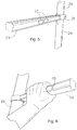
Fig. 5 . shows a perspective view of a portion of a ladder with a rung as infigure 3 and with slidable actuators, -
Fig. 6 shows the rung offigures 3 and5 with the slidable actuator, -
Figs. 7a-c show the slidable actuator, -
Fig. 8 shows a hand gripping a central portion of the rung offigure 5 , and -
Figs. 9a-d show a connector of a ladder assembly according to the invention. -
Figures 1 and 2 show an example of a ladder assembly, here embodied as a straighttelescopic ladder 1. As explained above the ladder assembly may also be part of another "ladder product" such as a stepladder or combination ladder, a work platform with ladder like telescopic legs, etc. - The
ladder 1 includes alowermost ladder section 2 having twotubular stile members 2a, b which are arranged parallel to each other. Eachstile member 2a, b of thelowermost ladder section 2 here is provided with a ground engagingfoot member 2c (e.g. of rubber or the like). - The
stile members 2a, b are interconnected at their upper ends by aladder rung 2d and in this example (as is preferred) also by alowermost ladder rung 2e. - The
ladder 1 further comprises at least two additional ladder sections; here seven additional ladder sections 3-9. These ladder sections 3-9 each have two tubular stile members arranged parallel to each other and interconnected at the upper end by a ladder rung to form a U-shaped ladder section. The stile members of each ladder section are telescopically inserted into the stile members of a lower and adjacent ladder section. - The
ladder 1 further comprising automatic latch mechanisms (as will be explained by example in more detail below) for locking the telescopically inserted stile members relative to one another when the ladder sections are extended, the latch mechanisms being associated with actuators for unlocking the stile members in order to allow for collapsing or retracting of the ladder assembly. - As can be seen in
figure 1 these actuators are manually operated actuators, indicated withreference numeral 10 infigure 1 , Theactuators 10 are the slidable actuators and are arranged centrally on the front side of therung 2d so as to be operable simultaneously with a single hand. - The
rungs 2d-9d are connected to the associatedstile members 2a, b viaconnectors 2f, g of which preferred embodiments will be illustrated with reference tofigures 9a-d . - Referring to
figures 3-9 now further aspects and preferred details of the ladder assembly according to the invention will now be explained. -
Figures 3, 4, 6 show a preferred design of a rung for a telescopic ladder, which is preferably incorporated in a ladder according to the invention. - Here the rung is considered to be any of the rungs of the
ladder 1 offigure 1 , so thatreference numeral 2d is used here. - The
rung 2d is made from an extruded aluminium tubular profile, the profile including atop wall 41, abottom wall 42, as well as afront wall 43 and arear wall 44 extending between the top wall and the bottom wall. Thefront wall 41 here corresponds to the side on which theslidable actuators 10 are mounted. As can be seen infigure 1 theslidable actuators 10 are arranged on the front side of the rung. - As is preferred the
top wall 41 is in cross section upwardly convex, whereas thebottom wall 42 is in cross section upwardly concave. As is preferred the curvature is identical so that in a design of the ladder wherein the rungs contact one another in collapsed state of the ladder (as is preferred) the top wall and bottom wall are in close contact (seefigure 4 ). This provides stability of the ladder in said collapsed condition and avoids items entering in the space between the rungs. - The front wall has an elongated recessed portion 43a extending over the entire length thereof. This recessed portion is offset inwardly with respect to the above and below located edge portions 43b, c of the
front wall 43. The rear wall has a similar recessed portion 44a. - As is also preferred (especially for manufacturing reasons) the front wall and rear wall are symmetrical. These recessed portions extend over a substantial portion of the height of the respective front and rear wall, preferably over at least 15 millimetres, more preferably between 15 and 25 millimetres. The depth may vary, and lies preferably between 3 and 6 millimetres. The rungs have a great stability, even when weakened by one or more holes or slots in a central region of the rung to accommodate one or more actuators for the latch mechanisms.
- The upper surface of the top wall of the rung is preferably provided with a pattern of axial grooves/ribs to avoid slipping of the feet of a person climbing the ladder.
- As can be seen in
figures 1 ,5 ,6 and8 theslidable actuators 10 are arranged in said recessed portion 43a. - As shown in
figures 1 ,5, 8 theslidable actuators 10 here are arranged centrally on the front side of therung 2d -9d so as to be operable simultaneously with a single hand. - In this example each
rung 2d is provided with two slots in the recessed portion 43a and each actuator 10 has a rear extension portion 11, which extends through a slot into the interior of the rung (seefigure 6 ). - As is preferred each of said rear extension portions 11 is connected to an operating rod (partly shown in
figure 9b with reference numeral 60) which extends inside said rung to the latch mechanism (not shown) at the outer end of the rung. - As is preferred the
slidable actuators 10 are not fully hidden within the recess, but protrude at the front of the rung at most 10 mm from the front side of the rung, preferably at most 5 millimetres, more preferably between 1 and 4 millimetres. This is depicted infigure 6 showing a forward protrusion of 2 mm. - By being hidden for a major part within the recess it is avoided that the
actuators 10 are damaged by the feet of someone climbing or descending the ladder and/or during storage and transportation. - As is also preferred the
manual slide actuators 10 are spaced apart at most 15 centimetres, more preferably at most 10 centimetres. This allows for easy single hand operation of bothactuators 10 in a central portion of the rung, so that the operator or ladder user can use his or hers other hand for other purposes, e.g. holding the ladder stable by grabbing the ladder at a higher location than theactuators 10 to be operated for release of a ladder section. - In combination with some "forward protrusion" these actuators then add to the grip that a person may have on a ladder rung when the person holds a hand centrally around the rung as is shown in
figure 8 . This is a normal routine for persons climbing and descending a ladder and any additional grip is useful. - For ergonomic reasons the
slidable actuators 10 preferably have a height of at least 10 millimetres, preferably between 15 and 25 millimetres. - As is shown in
figures 6, 7a-d the rear extension portions 11 of theactuators 10 preferably include a snap provision adapted to snap around the rod. This facilitates the assembly process of the ladder assembly. - Referring to
figures 9a-d now the invention will be explained in more detail. - The
figures 9a-d show a connector, hereconnector 2f, which connects a rung (such asrung 2d) at an end thereof to the upper end of a stile member (here 2a). It is noted that preferably all connectors of a ladder assembly are of generally the same design, albeit with dimensions adapted to the diameter of the stile member (as is shown infigure 1 and common for this field). - The
connector 2f has a body (here of a unitary plastic design) having arung portion 50, which is here -as is preferred - adapted to be inserted into the end of the rung and be fastened therein (e.g. by press fit or otherwise). The connector body further includes a first orfront collar segment 52 and a second orrear collar segment 54, thesesegments rung portion 50. - The two
collar segments collar segments - According to the invention the
first collar segment 52 extends over angle of between 120 and 150 degrees, more preferably between 130 and 140 degrees, with respect to thelongitudinal axis 55 of the rung, whereas thesecond collar segment 54 extends over a complementary angle. Infigures 9a-d the first collar segment extends over 135 degrees which is preferred. - The opposed ends of the collar segments are provided with a
bore 56 through which a screw or bolt is fitted (not shown), the bore e.g. having at one end a recess for a bolt head and a nut being recessed in the opposed collar segment end. - As is highly preferred the outer face of the
collar segments 52, 54 - at the opposed ends thereof - form a substantially triangular protrusion 57 with respect to adjacent portions of the outer face of the collar segments (as can be seen infigures 9a,b ). This protrusion 57 provides a body portion for accommodation of a fastener, such as a screw or a bolt, in a manner which is not laterally extending as with the Telesteps ladders. It has been found that this orientation of the split between the collar segments allows easy and accurate tensioning of the collar around the style, better than the known 180 degrees design and better and easier than the mentioned 90 degrees design of Core Distribution. - The body of the connector preferably is made of plastic material, preferably as a unitary body by injection moulding, preferably of fibre reinforced plastic material.
- The skilled person will appreciate that the body of the connector here includes a
passage 58 for a locking pin 60 (which can form an extension of or be connected to the mentioned rod attached to the slide actuators 10) and allows to accommodate aspring 61 for biasing said lockingpin 60 towards a locked position (commonly the stile member having an associated locking pin opening to receive said locking pin in extended state of the ladder section). - It will be appreciated that the invention may be applied in combination with telescopic ladder assemblies having actuators in close proximity to the ladder stile members, e.g. manual operated or automatic as in
EP 527 766 - As is preferred - and known in the art - the automatic latch mechanisms of the inventive ladder each include a locking pin having a length which is sufficient for extending through a locking hole of the ladder section positioned there above and into the hollow space inside the stile member and the stile member having an extension below the locking hole, so that when an upper ladder section is released and telescopically inserted into an intermediate ladder section, which is locked in relation to a lower ladder section by the locking pin of the lower ladder section engaging the locking hole of the intermediate ladder section, the upper ladder section being stopped in a safety position from being fully inserted in the intermediate ladder section, by a safe distance, e.g. between 3 and 10 cm, by engagement of the extension of the lower ends of the stile members of the upper ladder section with the locking pins of the lower ladder section extending through the locking holes into the hollow space of the stile members of the intermediate ladder section.
Claims (14)
- A telescopically extendable and collapsible ladder assembly (1) having at least three ladder sections (2-9), each of said ladder sections having two tubular stile members (2a, 2b) arranged parallel to each other and interconnected at one end by a ladder rung (2d-9d) to form a U-shaped ladder section; the stile members of each ladder section being telescopically inserted into the stile members of an adjacent ladder section,
the ladder assembly further comprising automatic latch mechanisms (60,61) for locking the telescopically inserted stile members relative to one another when the ladder sections are extended, the latch mechanisms being associated with one or more actuators (10) for unlocking the stile members in order to allow for collapsing of the ladder assembly,
wherein each ladder section includes a connector (2f) at each end of a rung, the connector (2f) having a rung portion (50) connected to the end of the rung and having a first (52) and a second (54) collar segment, each integral at one end thereof with the rung portion (50), the two collar segments (52, 54) substantially encircling the stile member (2a, 2b), the collar segments (52, 54) having spaced apart opposed ends, a fastener being provided bridging the opposed ends of the collar segments for securely coupling the collar segments around the stile member,
characterized in that
the first collar segment (52) extends over an angle of between 120 and 150 degrees with respect to the longitudinal axis of the rung (2d), whereas the second collar segment (54) extends over a complementary angle. - Ladder assembly according to claim 1, wherein the first collar segment (52) extends over an angle of between 130 and 140 degrees with respect to the longitudinal axis of the rung (2d).
- Ladder assembly according to claim 1 or 2, wherein the outer face of the collar segments at the opposed ends thereof form a substantially triangular protrusion (57) with respect to adjacent portions of the outer face of the collar segments.
- Ladder assembly according to claim 3, wherein the opposed ends of the collar segments are provided with a bore (56) through which a fastener is fitted.
- Ladder assembly according to one or more of the preceding claims, wherein the one or more actuators (10) associated with the latch mechanisms are arranged centrally on a ladder rung and are operable simultaneously with a single hand of the user.
- Ladder assembly according to one or more of the preceding claims, wherein the actuators (10) are arranged on a front side of the rung.
- Ladder assembly according to one or more of the preceding claims, wherein the connector has a unitary body made of plastic material.
- Ladder assembly according to one or more of the preceding claims, wherein a front wall (43) of the rung has an elongated recessed portion (43a) over the length thereof and the one or more actuators (10) are arranged in said recessed portion,
and wherein each actuator (10) extends through a slot in said front wall into the interior of the rung, each of said actuators being connected to a operating rod which extends inside said rung to the latch mechanism (60, 61) at the outer end of the rung. - Ladder assembly according to claim 8, wherein the one or more actuators protrude at the front of the rung at most 10 mm from the rung, preferably at most 5 millimetres, more preferably between 1 and 4 millimetres.
- Ladder assembly according to claim 8, wherein the one or more actuators have a height of at least 10 millimetres, preferably between 15 and 25 millimetres.
- Ladder assembly according to one or more of the preceding claims, wherein the ladder rungs (2d,9d) are made from an extruded aluminium tubular profile, the profile including a top wall, a bottom wall, as well as a front and a rear wall extending between the top wall and the bottom wall.
- Ladder assembly according to one or more of the preceding claims, wherein the rung has a top wall which is in cross section upwardly convex, whereas the bottom wall is in cross section upwardly concave.
- Ladder assembly according to claim 8, wherein the actuators are slidable actuators and each have a rear extension which includes a snap provision adapted to snap around the rod.
- Ladder assembly according to claim 11, wherein the front wall (43) and the rear wall (44) of the rung each have an elongated recessed portion (43a, 44a) over the length thereof, the recessed portion having a height of preferably between 15 and 25 millimetres, the recessed portion having a depth of at least 2 millimetres.
Applications Claiming Priority (3)
| Application Number | Priority Date | Filing Date | Title |
|---|---|---|---|
| NL1034629 | 2007-11-02 | ||
| PCT/NL2008/000033 WO2009057995A1 (en) | 2007-11-02 | 2008-01-30 | A telescopic ladder assembly |
| EP08705071.2A EP2215323B1 (en) | 2007-11-02 | 2008-01-30 | A telescopic ladder assembly |
Related Parent Applications (1)
| Application Number | Title | Priority Date | Filing Date |
|---|---|---|---|
| EP08705071.2A Division EP2215323B1 (en) | 2007-11-02 | 2008-01-30 | A telescopic ladder assembly |
Publications (3)
| Publication Number | Publication Date |
|---|---|
| EP2998501A1 EP2998501A1 (en) | 2016-03-23 |
| EP2998501B1 true EP2998501B1 (en) | 2018-10-10 |
| EP2998501B8 EP2998501B8 (en) | 2018-12-26 |
Family
ID=39684326
Family Applications (2)
| Application Number | Title | Priority Date | Filing Date |
|---|---|---|---|
| EP15188391.5A Active EP2998501B8 (en) | 2007-11-02 | 2008-01-30 | A telescopic ladder assembly |
| EP08705071.2A Active EP2215323B1 (en) | 2007-11-02 | 2008-01-30 | A telescopic ladder assembly |
Family Applications After (1)
| Application Number | Title | Priority Date | Filing Date |
|---|---|---|---|
| EP08705071.2A Active EP2215323B1 (en) | 2007-11-02 | 2008-01-30 | A telescopic ladder assembly |
Country Status (3)
| Country | Link |
|---|---|
| EP (2) | EP2998501B8 (en) |
| CN (2) | CN101918671B (en) |
| WO (1) | WO2009057995A1 (en) |
Families Citing this family (16)
| Publication number | Priority date | Publication date | Assignee | Title |
|---|---|---|---|---|
| US8225906B2 (en) | 2008-08-22 | 2012-07-24 | Core Distribution, Inc. | Extendable/retractable ladder |
| WO2011043663A1 (en) | 2009-10-07 | 2011-04-14 | Lampe Holding B.V. | Portable ladder with a stand off device |
| CN102140872A (en) * | 2011-03-05 | 2011-08-03 | 宁波超腾照明电器有限公司 | Safety telescopic ladder capable of being automatically gathered in slow descending mode under action of air resistance |
| CN102733751B (en) * | 2012-06-26 | 2015-02-25 | 宁波兴富工具有限公司 | Anti-hand-pinching safe telescopic ladder |
| FR3006361B1 (en) | 2013-05-29 | 2015-05-15 | Zhuhai Quan Da Industry Commerce Co Ltd | TELESCOPIC LADDER |
| EP3581754B1 (en) | 2014-08-18 | 2021-06-30 | Lampe Holding B.V. | Telescopic ladder assembly |
| ES2963810T3 (en) * | 2014-12-02 | 2024-04-02 | Core Distrib Inc | Telescopic ladder |
| US9416591B2 (en) | 2014-12-02 | 2016-08-16 | Core Distribution, Inc. | Telescoping ladder with stabilizers |
| US9580959B2 (en) | 2014-12-02 | 2017-02-28 | Core Distribution, Inc. | Foldable ladder |
| US10233692B2 (en) | 2014-12-02 | 2019-03-19 | Core Distribution, Inc. | Foldable ladder |
| CN206129129U (en) * | 2016-08-31 | 2017-04-26 | 东莞威信运动用品有限公司 | Flexible pipe buffering guide structure |
| WO2018088906A1 (en) * | 2016-11-14 | 2018-05-17 | Lampe Holding B.V. | Telescopic ladder assembly |
| US11174678B2 (en) | 2017-11-08 | 2021-11-16 | Core Distribution, Inc. | Locking assembly for a telescoping ladder |
| SE544747C2 (en) * | 2018-10-17 | 2022-11-01 | Telesteps Ab | A stabiliser system for a collapsible ladder |
| US11795760B2 (en) | 2019-10-24 | 2023-10-24 | Core Distribution, Inc. | Ladder tripod assembly and system |
| WO2023101584A1 (en) * | 2021-12-02 | 2023-06-08 | Telesteps Ab | A damping device and an asymmetric damping block adapted to be arranged in a damping device for a collapsible ladder, a collapsible ladder and a method for arranging a damping device in a collapsible ladder |
Family Cites Families (14)
| Publication number | Priority date | Publication date | Assignee | Title |
|---|---|---|---|---|
| US1712942A (en) * | 1927-12-29 | 1929-05-14 | Hiram K Smith | Collapsible ladder |
| US4574918A (en) * | 1982-01-21 | 1986-03-11 | Andral Corporation | Ladder locking mechanism |
| EP0527766B1 (en) | 1990-04-10 | 1996-06-05 | Bertschi, Bruno | Collapsible ladder |
| GB2263932B (en) | 1992-02-01 | 1995-06-28 | Telesteps Limited | Loft ladder |
| WO1995023907A1 (en) | 1994-03-01 | 1995-09-08 | Foxdale Developments Ltd. | Extensible ladder |
| US5645140A (en) * | 1995-05-08 | 1997-07-08 | Mouneimneh; Ghassoub A. | Self-supported collapsible ladder |
| EP0804677A1 (en) * | 1995-09-19 | 1997-11-05 | Kendall, Gerald R. | Foldable ladder |
| US5743355A (en) | 1996-07-31 | 1998-04-28 | Mcdonnell; Charles A. | Retractable ladder |
| IT1320835B1 (en) * | 2000-11-14 | 2003-12-10 | Campagnolo Srl | TIGHTENING CLAMP FOR THE SADDLE OF A BICYCLE. |
| SE523253C2 (en) * | 2001-06-13 | 2004-04-06 | Telesteps Ab | Foldable ladder |
| US6708800B2 (en) | 2002-08-02 | 2004-03-23 | Core Distribution, Inc. | Extending ladder and associated manufacturing methods |
| DE602006015234D1 (en) | 2005-12-30 | 2010-08-12 | Core Distrib Inc | ERGONOMIC EXTENDABLE / RETRACTABLE LADDER |
| US20070209875A1 (en) * | 2006-03-10 | 2007-09-13 | Mua-Mei Chen | Securing device for extending ladder |
| GB2436584B (en) * | 2006-03-30 | 2011-08-31 | Norman William Liefke | An extension ladder with improved mechanism |
-
2008
- 2008-01-30 CN CN2008801238043A patent/CN101918671B/en active Active
- 2008-01-30 EP EP15188391.5A patent/EP2998501B8/en active Active
- 2008-01-30 CN CN2011100659161A patent/CN102168521B/en active Active
- 2008-01-30 EP EP08705071.2A patent/EP2215323B1/en active Active
- 2008-01-30 WO PCT/NL2008/000033 patent/WO2009057995A1/en active Application Filing
Non-Patent Citations (1)
| Title |
|---|
| None * |
Also Published As
| Publication number | Publication date |
|---|---|
| EP2998501A1 (en) | 2016-03-23 |
| EP2215323A1 (en) | 2010-08-11 |
| EP2998501B8 (en) | 2018-12-26 |
| EP2215323B1 (en) | 2015-10-07 |
| CN102168521A (en) | 2011-08-31 |
| CN101918671A (en) | 2010-12-15 |
| CN101918671B (en) | 2012-11-07 |
| WO2009057995A1 (en) | 2009-05-07 |
| CN102168521B (en) | 2013-07-31 |
Similar Documents
| Publication | Publication Date | Title |
|---|---|---|
| EP2998501B1 (en) | A telescopic ladder assembly | |
| US10480245B2 (en) | Telescopic ladder assembly | |
| EP2034127B1 (en) | Extendable and retractable ladder | |
| EP3042019B1 (en) | Adjustable ladders, ladder components and related methods | |
| EP2711496B1 (en) | Portable ladder with a stand off device | |
| US20230349235A1 (en) | Extendable walkthrough device for ladders | |
| US20100116592A1 (en) | Adjustable Stepladder | |
| EP2999373B1 (en) | Equipment for use when sitting and when walking, skiing or the like | |
| US9151114B2 (en) | Telescopic ladder and locking mechanism thereof | |
| WO2010084135A1 (en) | A ladder | |
| US20130140423A1 (en) | Ladder attachment apparatus | |
| US7650898B2 (en) | Adjustable pole | |
| US8939256B2 (en) | Collapsible ladder | |
| US6244383B1 (en) | Ladder scaffold device | |
| US4926964A (en) | Step/extension ladder | |
| CA2633352A1 (en) | Ergonomic extendable/retractable ladder | |
| CN212716387U (en) | Ladder assembly, ladder and work platform | |
| CN109577743B (en) | Refrigerator handle and refrigerator | |
| WO2006106494A1 (en) | Combined stepladder and platform | |
| EP0940556B1 (en) | Arrangement on a ladder | |
| EP2172615B1 (en) | An accessory for a ladder, a ladder, and a method for mounting an accessory for a ladder on a ladder | |
| CA2699159A1 (en) | Safety device for a ladder | |
| ITMI20060769A1 (en) | REMOVABLE PROTECTION DEVICE FOR PIOLI STAIRS | |
| IES20060735A2 (en) | Combined stepladder and platform |
Legal Events
| Date | Code | Title | Description |
|---|---|---|---|
| PUAI | Public reference made under article 153(3) epc to a published international application that has entered the european phase |
Free format text: ORIGINAL CODE: 0009012 |
|
| AC | Divisional application: reference to earlier application |
Ref document number: 2215323 Country of ref document: EP Kind code of ref document: P |
|
| AK | Designated contracting states |
Kind code of ref document: A1 Designated state(s): AT BE BG CH CY CZ DE DK EE ES FI FR GB GR HR HU IE IS IT LI LT LU LV MC MT NL NO PL PT RO SE SI SK TR |
|
| 17P | Request for examination filed |
Effective date: 20160922 |
|
| RBV | Designated contracting states (corrected) |
Designated state(s): AT BE BG CH CY CZ DE DK EE ES FI FR GB GR HR HU IE IS IT LI LT LU LV MC MT NL NO PL PT RO SE SI SK TR |
|
| RIC1 | Information provided on ipc code assigned before grant |
Ipc: E06C 7/08 20060101ALI20180321BHEP Ipc: E06C 1/12 20060101AFI20180321BHEP |
|
| GRAP | Despatch of communication of intention to grant a patent |
Free format text: ORIGINAL CODE: EPIDOSNIGR1 |
|
| STAA | Information on the status of an ep patent application or granted ep patent |
Free format text: STATUS: GRANT OF PATENT IS INTENDED |
|
| INTG | Intention to grant announced |
Effective date: 20180430 |
|
| GRAS | Grant fee paid |
Free format text: ORIGINAL CODE: EPIDOSNIGR3 |
|
| GRAA | (expected) grant |
Free format text: ORIGINAL CODE: 0009210 |
|
| STAA | Information on the status of an ep patent application or granted ep patent |
Free format text: STATUS: THE PATENT HAS BEEN GRANTED |
|
| AC | Divisional application: reference to earlier application |
Ref document number: 2215323 Country of ref document: EP Kind code of ref document: P |
|
| AK | Designated contracting states |
Kind code of ref document: B1 Designated state(s): AT BE BG CH CY CZ DE DK EE ES FI FR GB GR HR HU IE IS IT LI LT LU LV MC MT NL NO PL PT RO SE SI SK TR |
|
| REG | Reference to a national code |
Ref country code: GB Ref legal event code: FG4D |
|
| REG | Reference to a national code |
Ref country code: CH Ref legal event code: EP Ref country code: CH Ref legal event code: PK Free format text: BERICHTIGUNGEN Ref country code: AT Ref legal event code: REF Ref document number: 1051459 Country of ref document: AT Kind code of ref document: T Effective date: 20181015 |
|
| RAP2 | Party data changed (patent owner data changed or rights of a patent transferred) |
Owner name: LAMPE HOLDING B.V. |
|
| REG | Reference to a national code |
Ref country code: IE Ref legal event code: FG4D |
|
| RIN2 | Information on inventor provided after grant (corrected) |
Inventor name: LAMPE, CASPAR BERNARD |
|
| REG | Reference to a national code |
Ref country code: DE Ref legal event code: R096 Ref document number: 602008057410 Country of ref document: DE |
|
| REG | Reference to a national code |
Ref country code: CH Ref legal event code: PK Free format text: BERICHTIGUNG B8 |
|
| REG | Reference to a national code |
Ref country code: DE Ref legal event code: R081 Ref document number: 602008057410 Country of ref document: DE Owner name: LAMPE HOLDING B.V., NL Free format text: FORMER OWNER: LAMPE HOLDING B.V., LUCHTHAVEN SCHIPHOL, NL |
|
| REG | Reference to a national code |
Ref country code: NL Ref legal event code: FP |
|
| REG | Reference to a national code |
Ref country code: SE Ref legal event code: TRGR |
|
| REG | Reference to a national code |
Ref country code: LT Ref legal event code: MG4D |
|
| REG | Reference to a national code |
Ref country code: AT Ref legal event code: MK05 Ref document number: 1051459 Country of ref document: AT Kind code of ref document: T Effective date: 20181010 |
|
| PG25 | Lapsed in a contracting state [announced via postgrant information from national office to epo] |
Ref country code: ES Free format text: LAPSE BECAUSE OF FAILURE TO SUBMIT A TRANSLATION OF THE DESCRIPTION OR TO PAY THE FEE WITHIN THE PRESCRIBED TIME-LIMIT Effective date: 20181010 Ref country code: LV Free format text: LAPSE BECAUSE OF FAILURE TO SUBMIT A TRANSLATION OF THE DESCRIPTION OR TO PAY THE FEE WITHIN THE PRESCRIBED TIME-LIMIT Effective date: 20181010 Ref country code: FI Free format text: LAPSE BECAUSE OF FAILURE TO SUBMIT A TRANSLATION OF THE DESCRIPTION OR TO PAY THE FEE WITHIN THE PRESCRIBED TIME-LIMIT Effective date: 20181010 Ref country code: HR Free format text: LAPSE BECAUSE OF FAILURE TO SUBMIT A TRANSLATION OF THE DESCRIPTION OR TO PAY THE FEE WITHIN THE PRESCRIBED TIME-LIMIT Effective date: 20181010 Ref country code: BG Free format text: LAPSE BECAUSE OF FAILURE TO SUBMIT A TRANSLATION OF THE DESCRIPTION OR TO PAY THE FEE WITHIN THE PRESCRIBED TIME-LIMIT Effective date: 20190110 Ref country code: PL Free format text: LAPSE BECAUSE OF FAILURE TO SUBMIT A TRANSLATION OF THE DESCRIPTION OR TO PAY THE FEE WITHIN THE PRESCRIBED TIME-LIMIT Effective date: 20181010 Ref country code: AT Free format text: LAPSE BECAUSE OF FAILURE TO SUBMIT A TRANSLATION OF THE DESCRIPTION OR TO PAY THE FEE WITHIN THE PRESCRIBED TIME-LIMIT Effective date: 20181010 Ref country code: LT Free format text: LAPSE BECAUSE OF FAILURE TO SUBMIT A TRANSLATION OF THE DESCRIPTION OR TO PAY THE FEE WITHIN THE PRESCRIBED TIME-LIMIT Effective date: 20181010 Ref country code: NO Free format text: LAPSE BECAUSE OF FAILURE TO SUBMIT A TRANSLATION OF THE DESCRIPTION OR TO PAY THE FEE WITHIN THE PRESCRIBED TIME-LIMIT Effective date: 20190110 Ref country code: IS Free format text: LAPSE BECAUSE OF FAILURE TO SUBMIT A TRANSLATION OF THE DESCRIPTION OR TO PAY THE FEE WITHIN THE PRESCRIBED TIME-LIMIT Effective date: 20190210 |
|
| PG25 | Lapsed in a contracting state [announced via postgrant information from national office to epo] |
Ref country code: GR Free format text: LAPSE BECAUSE OF FAILURE TO SUBMIT A TRANSLATION OF THE DESCRIPTION OR TO PAY THE FEE WITHIN THE PRESCRIBED TIME-LIMIT Effective date: 20190111 Ref country code: PT Free format text: LAPSE BECAUSE OF FAILURE TO SUBMIT A TRANSLATION OF THE DESCRIPTION OR TO PAY THE FEE WITHIN THE PRESCRIBED TIME-LIMIT Effective date: 20190210 |
|
| REG | Reference to a national code |
Ref country code: DE Ref legal event code: R097 Ref document number: 602008057410 Country of ref document: DE |
|
| PG25 | Lapsed in a contracting state [announced via postgrant information from national office to epo] |
Ref country code: CZ Free format text: LAPSE BECAUSE OF FAILURE TO SUBMIT A TRANSLATION OF THE DESCRIPTION OR TO PAY THE FEE WITHIN THE PRESCRIBED TIME-LIMIT Effective date: 20181010 Ref country code: DK Free format text: LAPSE BECAUSE OF FAILURE TO SUBMIT A TRANSLATION OF THE DESCRIPTION OR TO PAY THE FEE WITHIN THE PRESCRIBED TIME-LIMIT Effective date: 20181010 |
|
| PLBE | No opposition filed within time limit |
Free format text: ORIGINAL CODE: 0009261 |
|
| STAA | Information on the status of an ep patent application or granted ep patent |
Free format text: STATUS: NO OPPOSITION FILED WITHIN TIME LIMIT |
|
| PG25 | Lapsed in a contracting state [announced via postgrant information from national office to epo] |
Ref country code: SK Free format text: LAPSE BECAUSE OF FAILURE TO SUBMIT A TRANSLATION OF THE DESCRIPTION OR TO PAY THE FEE WITHIN THE PRESCRIBED TIME-LIMIT Effective date: 20181010 Ref country code: EE Free format text: LAPSE BECAUSE OF FAILURE TO SUBMIT A TRANSLATION OF THE DESCRIPTION OR TO PAY THE FEE WITHIN THE PRESCRIBED TIME-LIMIT Effective date: 20181010 Ref country code: MC Free format text: LAPSE BECAUSE OF FAILURE TO SUBMIT A TRANSLATION OF THE DESCRIPTION OR TO PAY THE FEE WITHIN THE PRESCRIBED TIME-LIMIT Effective date: 20181010 Ref country code: RO Free format text: LAPSE BECAUSE OF FAILURE TO SUBMIT A TRANSLATION OF THE DESCRIPTION OR TO PAY THE FEE WITHIN THE PRESCRIBED TIME-LIMIT Effective date: 20181010 |
|
| REG | Reference to a national code |
Ref country code: CH Ref legal event code: PL |
|
| 26N | No opposition filed |
Effective date: 20190711 |
|
| PG25 | Lapsed in a contracting state [announced via postgrant information from national office to epo] |
Ref country code: LU Free format text: LAPSE BECAUSE OF NON-PAYMENT OF DUE FEES Effective date: 20190130 |
|
| REG | Reference to a national code |
Ref country code: IE Ref legal event code: MM4A |
|
| PG25 | Lapsed in a contracting state [announced via postgrant information from national office to epo] |
Ref country code: SI Free format text: LAPSE BECAUSE OF FAILURE TO SUBMIT A TRANSLATION OF THE DESCRIPTION OR TO PAY THE FEE WITHIN THE PRESCRIBED TIME-LIMIT Effective date: 20181010 |
|
| PG25 | Lapsed in a contracting state [announced via postgrant information from national office to epo] |
Ref country code: LI Free format text: LAPSE BECAUSE OF NON-PAYMENT OF DUE FEES Effective date: 20190131 Ref country code: CH Free format text: LAPSE BECAUSE OF NON-PAYMENT OF DUE FEES Effective date: 20190131 |
|
| PG25 | Lapsed in a contracting state [announced via postgrant information from national office to epo] |
Ref country code: IE Free format text: LAPSE BECAUSE OF NON-PAYMENT OF DUE FEES Effective date: 20190130 |
|
| PG25 | Lapsed in a contracting state [announced via postgrant information from national office to epo] |
Ref country code: TR Free format text: LAPSE BECAUSE OF FAILURE TO SUBMIT A TRANSLATION OF THE DESCRIPTION OR TO PAY THE FEE WITHIN THE PRESCRIBED TIME-LIMIT Effective date: 20181010 |
|
| PG25 | Lapsed in a contracting state [announced via postgrant information from national office to epo] |
Ref country code: MT Free format text: LAPSE BECAUSE OF NON-PAYMENT OF DUE FEES Effective date: 20190130 |
|
| PG25 | Lapsed in a contracting state [announced via postgrant information from national office to epo] |
Ref country code: CY Free format text: LAPSE BECAUSE OF FAILURE TO SUBMIT A TRANSLATION OF THE DESCRIPTION OR TO PAY THE FEE WITHIN THE PRESCRIBED TIME-LIMIT Effective date: 20181010 |
|
| PG25 | Lapsed in a contracting state [announced via postgrant information from national office to epo] |
Ref country code: HU Free format text: LAPSE BECAUSE OF FAILURE TO SUBMIT A TRANSLATION OF THE DESCRIPTION OR TO PAY THE FEE WITHIN THE PRESCRIBED TIME-LIMIT; INVALID AB INITIO Effective date: 20080130 |
|
| PGFP | Annual fee paid to national office [announced via postgrant information from national office to epo] |
Ref country code: FR Payment date: 20230125 Year of fee payment: 16 |
|
| PGFP | Annual fee paid to national office [announced via postgrant information from national office to epo] |
Ref country code: SE Payment date: 20230125 Year of fee payment: 16 Ref country code: IT Payment date: 20230125 Year of fee payment: 16 Ref country code: GB Payment date: 20230126 Year of fee payment: 16 Ref country code: DE Payment date: 20230123 Year of fee payment: 16 Ref country code: BE Payment date: 20230127 Year of fee payment: 16 |
|
| P01 | Opt-out of the competence of the unified patent court (upc) registered |
Effective date: 20230519 |
|
| PGFP | Annual fee paid to national office [announced via postgrant information from national office to epo] |
Ref country code: NL Payment date: 20230127 Year of fee payment: 16 |
|
| PGFP | Annual fee paid to national office [announced via postgrant information from national office to epo] |
Ref country code: NL Payment date: 20240124 Year of fee payment: 17 |