EP2998210A1 - Air intake device for two-wheeled motor vehicle - Google Patents
Air intake device for two-wheeled motor vehicle Download PDFInfo
- Publication number
- EP2998210A1 EP2998210A1 EP14798115.3A EP14798115A EP2998210A1 EP 2998210 A1 EP2998210 A1 EP 2998210A1 EP 14798115 A EP14798115 A EP 14798115A EP 2998210 A1 EP2998210 A1 EP 2998210A1
- Authority
- EP
- European Patent Office
- Prior art keywords
- intake
- air
- port
- main
- main frame
- Prior art date
- Legal status (The legal status is an assumption and is not a legal conclusion. Google has not performed a legal analysis and makes no representation as to the accuracy of the status listed.)
- Granted
Links
Images


Classifications
-
- F—MECHANICAL ENGINEERING; LIGHTING; HEATING; WEAPONS; BLASTING
- F02—COMBUSTION ENGINES; HOT-GAS OR COMBUSTION-PRODUCT ENGINE PLANTS
- F02M—SUPPLYING COMBUSTION ENGINES IN GENERAL WITH COMBUSTIBLE MIXTURES OR CONSTITUENTS THEREOF
- F02M35/00—Combustion-air cleaners, air intakes, intake silencers, or induction systems specially adapted for, or arranged on, internal-combustion engines
- F02M35/16—Combustion-air cleaners, air intakes, intake silencers, or induction systems specially adapted for, or arranged on, internal-combustion engines characterised by use in vehicles
- F02M35/162—Motorcycles; All-terrain vehicles, e.g. quads, snowmobiles; Small vehicles, e.g. forklifts
-
- B—PERFORMING OPERATIONS; TRANSPORTING
- B62—LAND VEHICLES FOR TRAVELLING OTHERWISE THAN ON RAILS
- B62K—CYCLES; CYCLE FRAMES; CYCLE STEERING DEVICES; RIDER-OPERATED TERMINAL CONTROLS SPECIALLY ADAPTED FOR CYCLES; CYCLE AXLE SUSPENSIONS; CYCLE SIDECARS, FORECARS, OR THE LIKE
- B62K11/00—Motorcycles, engine-assisted cycles or motor scooters with one or two wheels
- B62K11/02—Frames
- B62K11/04—Frames characterised by the engine being between front and rear wheels
-
- F—MECHANICAL ENGINEERING; LIGHTING; HEATING; WEAPONS; BLASTING
- F02—COMBUSTION ENGINES; HOT-GAS OR COMBUSTION-PRODUCT ENGINE PLANTS
- F02M—SUPPLYING COMBUSTION ENGINES IN GENERAL WITH COMBUSTIBLE MIXTURES OR CONSTITUENTS THEREOF
- F02M35/00—Combustion-air cleaners, air intakes, intake silencers, or induction systems specially adapted for, or arranged on, internal-combustion engines
- F02M35/02—Air cleaners
- F02M35/0201—Housings; Casings; Frame constructions; Lids; Manufacturing or assembling thereof
- F02M35/0204—Housings; Casings; Frame constructions; Lids; Manufacturing or assembling thereof for connecting or joining to other devices, e.g. pipes
-
- F—MECHANICAL ENGINEERING; LIGHTING; HEATING; WEAPONS; BLASTING
- F02—COMBUSTION ENGINES; HOT-GAS OR COMBUSTION-PRODUCT ENGINE PLANTS
- F02M—SUPPLYING COMBUSTION ENGINES IN GENERAL WITH COMBUSTIBLE MIXTURES OR CONSTITUENTS THEREOF
- F02M35/00—Combustion-air cleaners, air intakes, intake silencers, or induction systems specially adapted for, or arranged on, internal-combustion engines
- F02M35/02—Air cleaners
- F02M35/04—Air cleaners specially arranged with respect to engine, to intake system or specially adapted to vehicle; Mounting thereon ; Combinations with other devices
- F02M35/044—Special arrangements of cleaners in or with respect to the air intake system, e.g. in the intake plenum, in ducts or with respect to carburettors
-
- F—MECHANICAL ENGINEERING; LIGHTING; HEATING; WEAPONS; BLASTING
- F02—COMBUSTION ENGINES; HOT-GAS OR COMBUSTION-PRODUCT ENGINE PLANTS
- F02M—SUPPLYING COMBUSTION ENGINES IN GENERAL WITH COMBUSTIBLE MIXTURES OR CONSTITUENTS THEREOF
- F02M35/00—Combustion-air cleaners, air intakes, intake silencers, or induction systems specially adapted for, or arranged on, internal-combustion engines
- F02M35/02—Air cleaners
- F02M35/04—Air cleaners specially arranged with respect to engine, to intake system or specially adapted to vehicle; Mounting thereon ; Combinations with other devices
- F02M35/048—Arranging or mounting on or with respect to engines or vehicle bodies
-
- F—MECHANICAL ENGINEERING; LIGHTING; HEATING; WEAPONS; BLASTING
- F02—COMBUSTION ENGINES; HOT-GAS OR COMBUSTION-PRODUCT ENGINE PLANTS
- F02M—SUPPLYING COMBUSTION ENGINES IN GENERAL WITH COMBUSTIBLE MIXTURES OR CONSTITUENTS THEREOF
- F02M35/00—Combustion-air cleaners, air intakes, intake silencers, or induction systems specially adapted for, or arranged on, internal-combustion engines
- F02M35/10—Air intakes; Induction systems
- F02M35/10006—Air intakes; Induction systems characterised by the position of elements of the air intake system in direction of the air intake flow, i.e. between ambient air inlet and supply to the combustion chamber
- F02M35/10013—Means upstream of the air filter; Connection to the ambient air
-
- F—MECHANICAL ENGINEERING; LIGHTING; HEATING; WEAPONS; BLASTING
- F02—COMBUSTION ENGINES; HOT-GAS OR COMBUSTION-PRODUCT ENGINE PLANTS
- F02M—SUPPLYING COMBUSTION ENGINES IN GENERAL WITH COMBUSTIBLE MIXTURES OR CONSTITUENTS THEREOF
- F02M35/00—Combustion-air cleaners, air intakes, intake silencers, or induction systems specially adapted for, or arranged on, internal-combustion engines
- F02M35/10—Air intakes; Induction systems
- F02M35/10091—Air intakes; Induction systems characterised by details of intake ducts: shapes; connections; arrangements
- F02M35/10144—Connections of intake ducts to each other or to another device
-
- F—MECHANICAL ENGINEERING; LIGHTING; HEATING; WEAPONS; BLASTING
- F02—COMBUSTION ENGINES; HOT-GAS OR COMBUSTION-PRODUCT ENGINE PLANTS
- F02M—SUPPLYING COMBUSTION ENGINES IN GENERAL WITH COMBUSTIBLE MIXTURES OR CONSTITUENTS THEREOF
- F02M35/00—Combustion-air cleaners, air intakes, intake silencers, or induction systems specially adapted for, or arranged on, internal-combustion engines
- F02M35/10—Air intakes; Induction systems
- F02M35/10314—Materials for intake systems
- F02M35/10321—Plastics; Composites; Rubbers
-
- F—MECHANICAL ENGINEERING; LIGHTING; HEATING; WEAPONS; BLASTING
- F02—COMBUSTION ENGINES; HOT-GAS OR COMBUSTION-PRODUCT ENGINE PLANTS
- F02M—SUPPLYING COMBUSTION ENGINES IN GENERAL WITH COMBUSTIBLE MIXTURES OR CONSTITUENTS THEREOF
- F02M35/00—Combustion-air cleaners, air intakes, intake silencers, or induction systems specially adapted for, or arranged on, internal-combustion engines
- F02M35/10—Air intakes; Induction systems
- F02M35/10091—Air intakes; Induction systems characterised by details of intake ducts: shapes; connections; arrangements
- F02M35/10124—Ducts with special cross-sections, e.g. non-circular cross-section
-
- Y—GENERAL TAGGING OF NEW TECHNOLOGICAL DEVELOPMENTS; GENERAL TAGGING OF CROSS-SECTIONAL TECHNOLOGIES SPANNING OVER SEVERAL SECTIONS OF THE IPC; TECHNICAL SUBJECTS COVERED BY FORMER USPC CROSS-REFERENCE ART COLLECTIONS [XRACs] AND DIGESTS
- Y02—TECHNOLOGIES OR APPLICATIONS FOR MITIGATION OR ADAPTATION AGAINST CLIMATE CHANGE
- Y02T—CLIMATE CHANGE MITIGATION TECHNOLOGIES RELATED TO TRANSPORTATION
- Y02T10/00—Road transport of goods or passengers
- Y02T10/10—Internal combustion engine [ICE] based vehicles
- Y02T10/12—Improving ICE efficiencies
Definitions
- the present invention relates to an air intake device for a motorcycle in which an air intake sound is reduced and an engine performance is improved.
- the patent document 1 listed below discloses a conventional air intake device for a motorcycle of a design in which air is introduced from an air intake port into a motorcycle frame structure and then, an air is introduced into an air cleaner main body through an intake port communicated with an intake air discharge port in the motorcycle frame structure.
- Patent Document 1 JP Laid-open Patent Publication No. 2011-137431
- the conventional technique since the air intake port of the air cleaner has a limited open area, the conventional technique is unable to meet sufficiently the recent demands to increase the air intake efficiency and to increase the engine performance.
- the increase of the open area of the intake port of the air cleaner necessitates a concomitant increase of the open area of the intake air discharge port in the motorcycle frame structure that is in communication with the intake port of the air cleaner and, hence, the rigidity of the motorcycle frame structure is adversely affected.
- the present invention has been devised to provide a motorcycle air intake device in which the air intake efficiency is increased to increase the engine performance and to improve the acoustic quality of sounds of air being introduced.
- a motorcycle air intake device in accordance with the present invention includes: an air cleaner having an front end formed with a main intake port, the air cleaner being positioned between a pair of left and right main frame pieces forming a main frame; introducing passage defined within the main frame to capture an incoming wind as an engine intake air; an intake air introducing port of the introducing passage provided in a portion of the main frame piece at a location rearwardly of the main intake port in the air cleaner; an intake air discharge port defined in an intermediate portion of a front portion of the main frame with respect to a motorcycle widthwise direction, the intake air discharge port being opened rearwardly and fluid connected with the main intake port; and a sub intake port provided in communication with the main intake port to introduce an intake air from a location in the vicinity of the main intake port into the main intake port.
- the incoming air taken from the intake air introducing port in the main frame as an engine intake air is supplied from the main intake port in the air cleaner into the air cleaner that is fluid connected with the intake air discharge port in the main frame.
- the introducing port of the introducing passage referred to above is defined in a portion of the main frame piece, which is situated rearwardly of the main intake port of the air cleaner, and the intermediate portion of the front portion of the main frame with respect to the motorcycle widthwise direction is formed with the intake air discharge port that is opened rearwardly and fluid connected with the main intake port. Therefore, the introducing passage within the main frame is increased in length and, accordingly, intake air sounds are reduced.
- the intake air is also introduced from the sub intake port into the main intake port, the surface area of the intake port is substantially increased. Accordingly, the amount of air sucked into the air cleaner is increased to thereby increase the air intake efficiency, resulting in an increase of the engine performance. Furthermore, since the main frame itself can be used with the conventional parts in the form as they are, the manufacturing cost can be suppressed to a low cost.
- the sub intake port is preferably disposed on a lower side of the main intake port. This structural feature makes it possible to avoid an undesirable intrusion of rain into the sub intake port.
- the air cleaner preferably has a tip end having an intake duct in which the main intake port is formed, and the intake duct has a peripheral wall provided with a cutout portion, which is provided with the sub intake port.
- the sub intake port can be formed with a simplified structure merely by cutting out a peripheral wall of the intake duct.
- the intake duct preferably has a tip end portion fluid connected with the intake air discharge port through a connecting ring made of an elastic material, in which case the connecting ring is provided with a guide portion that protrude downwardly and forwardly from the main intake port to introduce the intake air into the sub intake port.
- the connecting ring which is made of the elastic material
- the sub intake port can be easily formed by a combination of the guide portion of the connecting ring and the cutout portion in the intake duct.
- the air cleaner and the main frame are connected together by means of the connecting ring made of the elastic material, and therefore, air tightness is secured, whereby upward and lateral leakage of intake sounds can be reduced.
- the connecting ring is preferably mounted on an outer periphery of the tip end portion of the intake duct and has a pawl portion engageable with an outer wall surface in the vicinity of the intake air discharge port in the main frame.
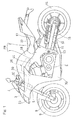
- Fig. 1 illustrates a schematic side view of a motorcycle equipped with an air intake device designed in accordance with a preferred embodiment of the present invention.
- the illustrated motorcycle has a motorcycle frame structure FR which includes a main frame 1, foiming a front half unit thereof, and a rear frame 2 connected with a rear portion of the main frame 1 and forming a rear half unit thereof.
- a head pipe 3 is fitted to a front end portion of the main frame 1; an upper bracket 4 and an under bracket 5 are fitted to a steering shaft (not shown) that is rotatably inserted in the head pipe 3.
- a front fork 8 is supported by the upper bracket 4 and the under bracket 5, and a front wheel 9 is supported by a lower end portion of the front fork 8.
- a handlebar 10 is fitted to the upper bracket 4 at an upper end portion of the front fork 8.
- a swingarm bracket 11 is provided in a rear end portion of the main frame 1, and a swingarm 12 is supported by the swingarm bracket 11 through a pivot pin 13, inserted in a front end portion of the swingarm 12, for swinging movement up and down.
- a rear wheel 14 is supported by a rear end portion of the swingarm 12.
- a combustion engine E is supported by a lower portion of the main frame 1, and the combustion engine E drives the rear wheel 14 through a power transmission mechanism 16 such as, for example, a drive chain.
- the combustion engine E employed in the practice of this embodiment is, for example, a four cylinder, four cycle water-cooling engine.
- a rider's seat 22 is supported by the rear frame 2, and a fuel tank 18 is fitted to an upper portion of the main frame 1, that is, to an upper portion of a motorcycle body and between the handlebar 10 and the rider's seat 22.
- a region beneath the rider's seat 22 is laterally covered by a side covering 17.
- a large sized front fairing 30 enough to cover a large region ranging from a front end portion of the motorcycle body to a location laterally of the combustion engine E is mounted on a motorcycle front portion, and a headlamp unit 23 is mounted on the front fairing 30.
- An air cleaner 36 is disposed in the vicinity of the rear portion of the head pipe 3.
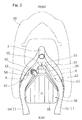
- the main frame 1 includes a pair of left and right main frame pieces 1a and 1b.
- the air cleaner 36 is positioned between the frame pieces 1a and 1b and in the vicinity of the rear portion of the head pipe 3.
- a front portion of the air cleaner 36 is supported by the main frame 1 by means of a connecting member 60 such as, for example, a bolt through a tank bracket 59 as will be detained later.
- a rear portion of the air cleaner 36 is supported by a throttle body 44 of the combustion engine E shown in Fig. 1 .
- Fig. 3 illustrates a schematic side view showing an air intake device and its neighborhood.
- an intake air discharge port 39 opens rearwardly.
- Intake air introducing ports 40 are opened in opposite side faces of the main frame 1.
- the main frame 1 has a hollow in which an introducing passage 43 is formed for introducing an incoming wind, which is captured as an engine intake air A through the intake air introducing ports 40 shown in Fig. 2 , forwardly to the intake air discharge port 39.
- the air cleaner 36 has a main intake port 41, best shown in Fig. 3 , which is fluid connected with the intake air discharge port 39 in the main frame 1 via a connecting ring 50.
- a sub intake port 42 for capturing an additional air protrudes downwardly from the air cleaner 36 and is exposed to the outside of the main intake port 41.
- the air cleaner 36 includes a lower casing 37 and a covering 38 for covering an upper portion of the lower casing 37.
- Each of the lower casing 37 and the covering 38 is made of a resinous material.
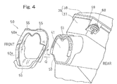
- Fig. 4 illustrates a condition in which the connecting ring 50 is removed from a tip end of an intake duct 51 of the air cleaner 36.
- the main intake port 41 of the air cleaner 36 is formed in a tip end of the intake duct 51, and the connecting ring 50 is mounted on the intake duct 51 by inserting the former in a direction shown by the arrow P.
- the connecting ring 50 can be separated from the intake duct 51, during the maintenance, by pulling the connecting ring 50 in a direction shown by the arrow Q.
- the shape of the main intake port 41 of the intake duct 51 substantially coincides with the shape of the intake air discharge port 39 defined in the intermediate portion of the front portion of the main frame 1, shown in Fig. 6 , with respect to the motorcycle widthwise direction.
- the intake duct 51 shown in Fig. 4 , has a peripheral wall in which a lower portion of the tip end is cut out to form a cutout portion 53.
- the connecting ring 50 is made of an elastic material such as, for example, rubber material and has an exterior shape sufficient to cover a tip end portion of the peripheral wall of the intake duct 51.
- the connecting ring 50 is somewhat undersized as compared with a peripheral wall dimension of the intake duct 51 so that, when the connecting ring 50 is inserted into the peripheral wall of the intake duct 51 in the direction of the arrow P, the connecting ring 50 can be elastically supported with no gap formed between the connecting ring 50 and the intake duct 51. In this way, by the connecting ring 50, the main intake port 41 of the intake duct 51 and the cutout portion 53 are covered from an outer peripheral side. A pair of left and right pawls 55 and 55 are formed in an upper side of the connecting ring 50. Also, the connecting ring 50 has a lower portion formed with a guide portion 56 so as to protrude downwardly.
- the connecting ring 50 has a front face 50a which serves as a sealing face.
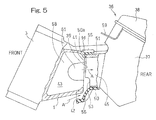
- Fig. 5 is a longitudinal sectional view showing a condition of connection between the intake duct 51 of the air cleaner 36 and the main frame 1.
- the front face 50a of the connecting ring 50 is brought into contact under pressure with a peripheral edge portion of the intake air discharge port 39 in the main frame 1 to thereby seal a gap between the main intake port 41 and the intake air discharge port 39.
- the pawls 55 are elastically pressed against and are hence engaged with an outer wall surface Id of an upper side of the main frame 1.
- the cutout portion 53 in the intake duct 51 of the air cleaner 36 and the guide portion 56 of the connecting ring 50 cooperate with each other to form the sub intake port 42 referred to previously.
- the intake discharge port 39 has a pair of left and right oval openings 57 and 57 with a partition wall 58 formed between those openings 57 and 57.
- the partition wall 58 is formed with a communicating port 61 best shown in Fig. 5 .
- the intake air A having passed through the left and right introducing passages 43 within the main frame 1 is guided rearwardly by the partition wall 58 and at this time sufficiently mixed through the communicating port 61.
- the intake air A is then guided into the air cleaner 36 through the intake air discharge port 39 by way of the main intake port 41 in the air cleaner 36.
- the air intake device of the construction as hereinbefore fully described is of such a design that, as shown in Fig. 3 , the incoming air taken from the intake air introducing port 40 in the main frame 1 as an engine intake air A is introduced from the main intake port 41 of the air cleaner 36 into the air cleaner 36 that is fluid connected with the intake air discharge port 39 in the main frame 1. At this time, as shown in Fig.
- the introducing port 40 of the introducing passage 43 referred to previously is defined in a portion of each of the main frame pieces 1a and 1b, which is situated rearwardly of the main intake port 41 of the air cleaner 36, and the intermediate portion of the front portion of the main frame with respect to the motorcycle widthwise direction is formed with the intake air discharge port 39 that is opened rearwardly and fluid connected with the main intake port 41. Therefore, the introducing passage 43 within the main frame 1 is increased in length, whereby intake air sounds are reduced.
- the intake air A is also introduced from the sub intake port 42 into the main intake port 41 and an in-duct air intake passage 45, the surface area of the intake port is substantially increased. Accordingly, the amount of air sucked into the air cleaner 36 is increased to thereby increase the air intake efficiency, resulting in an increase of the engine performance. Also, since the intake air A introduced from the sub intake port 42 does not flow through the introducing passage 43 within the main frame 1, the air intake resistance or pipe loss is reduced. Furthermore, since the sub intake port 42 is provided in the intake duct 51 of the air cleaner 36, the main frame 1 itself can be used with the conventional parts in the form as they are. Accordingly, the manufacturing cost can be suppressed to a low level.
- the sub intake port 42 is disposed on a lower side of the main intake port 41, an undesirable intrusion of rain into the sub intake port 42 can be avoided. Also, with a simplified structure in which the cutout portion 53 is formed in the peripheral wall of the intake duct 51 by merely cutting, the sub intake port 42 can be formed.
- the sub intake port 42 can be easily formed by a combination of the guide portion 56 of the connecting ring 50 and the cutout portion 53 in the intake duct 51.
- the air cleaner 36 and the main frame 1 are connected together by means of the connecting ring 50 made of the elastic material, and therefore, air tightness is secured, whereby upward and lateral leakage of intake sounds can be reduced.
- the connecting ring 50 is connected with the main frame 1 in a stable fashion by means of the pawls 55 in the connecting ring 50.
Landscapes
- Engineering & Computer Science (AREA)
- Mechanical Engineering (AREA)
- Chemical & Material Sciences (AREA)
- Combustion & Propulsion (AREA)
- General Engineering & Computer Science (AREA)
- Manufacturing & Machinery (AREA)
- Automatic Cycles, And Cycles In General (AREA)
Abstract
Description
- This application is based on and claims Convention priority to Japanese patent application No.
2013-105144, filed May 17, 2013 - The present invention relates to an air intake device for a motorcycle in which an air intake sound is reduced and an engine performance is improved.
- The
patent document 1 listed below, for example, discloses a conventional air intake device for a motorcycle of a design in which air is introduced from an air intake port into a motorcycle frame structure and then, an air is introduced into an air cleaner main body through an intake port communicated with an intake air discharge port in the motorcycle frame structure. - Patent Document 1:
JP Laid-open Patent Publication No. 2011-137431 - It has, however, been found that, according to the above mentioned conventional technique, since the air intake port of the air cleaner has a limited open area, the conventional technique is unable to meet sufficiently the recent demands to increase the air intake efficiency and to increase the engine performance. Although it may be contemplated to increase the air intake efficiency by increasing the open area of the intake port of the air cleaner, the increase of the open area of the intake port of the air cleaner necessitates a concomitant increase of the open area of the intake air discharge port in the motorcycle frame structure that is in communication with the intake port of the air cleaner and, hence, the rigidity of the motorcycle frame structure is adversely affected.
- In view of foregoing, the present invention has been devised to provide a motorcycle air intake device in which the air intake efficiency is increased to increase the engine performance and to improve the acoustic quality of sounds of air being introduced.
- In order to accomplish the foregoing object, a motorcycle air intake device in accordance with the present invention includes: an air cleaner having an front end formed with a main intake port, the air cleaner being positioned between a pair of left and right main frame pieces forming a main frame; introducing passage defined within the main frame to capture an incoming wind as an engine intake air; an intake air introducing port of the introducing passage provided in a portion of the main frame piece at a location rearwardly of the main intake port in the air cleaner; an intake air discharge port defined in an intermediate portion of a front portion of the main frame with respect to a motorcycle widthwise direction, the intake air discharge port being opened rearwardly and fluid connected with the main intake port; and a sub intake port provided in communication with the main intake port to introduce an intake air from a location in the vicinity of the main intake port into the main intake port.
- According to the present invention, the incoming air taken from the intake air introducing port in the main frame as an engine intake air is supplied from the main intake port in the air cleaner into the air cleaner that is fluid connected with the intake air discharge port in the main frame. At this time, the introducing port of the introducing passage referred to above is defined in a portion of the main frame piece, which is situated rearwardly of the main intake port of the air cleaner, and the intermediate portion of the front portion of the main frame with respect to the motorcycle widthwise direction is formed with the intake air discharge port that is opened rearwardly and fluid connected with the main intake port. Therefore, the introducing passage within the main frame is increased in length and, accordingly, intake air sounds are reduced. Also, since the intake air is also introduced from the sub intake port into the main intake port, the surface area of the intake port is substantially increased. Accordingly, the amount of air sucked into the air cleaner is increased to thereby increase the air intake efficiency, resulting in an increase of the engine performance. Furthermore, since the main frame itself can be used with the conventional parts in the form as they are, the manufacturing cost can be suppressed to a low cost.
- In a preferred embodiment of the present invention, the sub intake port is preferably disposed on a lower side of the main intake port. This structural feature makes it possible to avoid an undesirable intrusion of rain into the sub intake port.
- In another preferred embodiment of the present invention, the air cleaner preferably has a tip end having an intake duct in which the main intake port is formed, and the intake duct has a peripheral wall provided with a cutout portion, which is provided with the sub intake port. According to this structural feature, the sub intake port can be formed with a simplified structure merely by cutting out a peripheral wall of the intake duct.
- In a further preferred embodiment of the present invention, the intake duct preferably has a tip end portion fluid connected with the intake air discharge port through a connecting ring made of an elastic material, in which case the connecting ring is provided with a guide portion that protrude downwardly and forwardly from the main intake port to introduce the intake air into the sub intake port. According to this structural feature, merely by mounting the connecting ring, which is made of the elastic material, on the intake duct, the sub intake port can be easily formed by a combination of the guide portion of the connecting ring and the cutout portion in the intake duct. The air cleaner and the main frame are connected together by means of the connecting ring made of the elastic material, and therefore, air tightness is secured, whereby upward and lateral leakage of intake sounds can be reduced.
- In a still further referred embodiment of the present invention, the connecting ring is preferably mounted on an outer periphery of the tip end portion of the intake duct and has a pawl portion engageable with an outer wall surface in the vicinity of the intake air discharge port in the main frame. According to this structural feature, when the front portion of the main frame and the tip end of the intake duct are connected together through the connecting ring, the connecting ring is connected with the main frame in a stable fashion by means of the pawls in the connecting ring.
- Any combination of at least two constructions, disclosed in the appended claims and/or the specification and/or the accompanying drawings should be construed as included within the scope of the present invention. In particular, any combination of two or more of the appended claims should be equally construed as included within the scope of the present invention.
- In any event, the present invention will become more clearly understood from the following description of preferred embodiments thereof, when taken in conjunction with the accompanying drawings. However, the embodiments and the drawings are given only for the purpose of illustration and explanation, and are not to be taken as limiting the scope of the present invention in any way whatsoever, which scope is to be determined by the appended claims. In the accompanying drawings, like reference numerals are used to denote like parts throughout the several views, and:
-
Fig. 1 is a schematic side view showing a motorcycle equipped with an air intake device designed in accordance with a preferred embodiment of the present invention; -
Fig. 2 is a schematic fragmentary top plan view showing, on an enlarged scale, the air intake device and its vicinity; -
Fig. 3 is a schematic fragmentary side view showing, on an enlarged scale, the air intake device and its vicinity; -
Fig. 4 is a perspective view showing the air intake device with a connecting ring removed from an intake duct tip end of an air cleaner; -
Fig. 5 is a schematic longitudinal sectional view showing a connection between an intake duct of the air cleaner and a main frame; and -
Fig. 6 is a schematic rear view of the main frame as viewed from rear. - Hereinafter, a preferred embodiment of the present invention will be described in detail with particular reference to the accompanying drawings.
Fig. 1 illustrates a schematic side view of a motorcycle equipped with an air intake device designed in accordance with a preferred embodiment of the present invention. The illustrated motorcycle has a motorcycle frame structure FR which includes amain frame 1, foiming a front half unit thereof, and arear frame 2 connected with a rear portion of themain frame 1 and forming a rear half unit thereof. Ahead pipe 3 is fitted to a front end portion of themain frame 1; an upper bracket 4 and an underbracket 5 are fitted to a steering shaft (not shown) that is rotatably inserted in thehead pipe 3. A front fork 8 is supported by the upper bracket 4 and the underbracket 5, and a front wheel 9 is supported by a lower end portion of the front fork 8. Ahandlebar 10 is fitted to the upper bracket 4 at an upper end portion of the front fork 8. - A
swingarm bracket 11 is provided in a rear end portion of themain frame 1, and aswingarm 12 is supported by theswingarm bracket 11 through apivot pin 13, inserted in a front end portion of theswingarm 12, for swinging movement up and down. Arear wheel 14 is supported by a rear end portion of theswingarm 12. A combustion engine E is supported by a lower portion of themain frame 1, and the combustion engine E drives therear wheel 14 through apower transmission mechanism 16 such as, for example, a drive chain. The combustion engine E employed in the practice of this embodiment is, for example, a four cylinder, four cycle water-cooling engine. - A rider's
seat 22 is supported by therear frame 2, and afuel tank 18 is fitted to an upper portion of themain frame 1, that is, to an upper portion of a motorcycle body and between thehandlebar 10 and the rider'sseat 22. A region beneath the rider'sseat 22 is laterally covered by a side covering 17. A large sizedfront fairing 30 enough to cover a large region ranging from a front end portion of the motorcycle body to a location laterally of the combustion engine E is mounted on a motorcycle front portion, and aheadlamp unit 23 is mounted on thefront fairing 30. Anair cleaner 36 is disposed in the vicinity of the rear portion of thehead pipe 3. - As shown in
Fig. 2 , themain frame 1 includes a pair of left and rightmain frame pieces air cleaner 36 is positioned between theframe pieces head pipe 3. A front portion of theair cleaner 36 is supported by themain frame 1 by means of a connectingmember 60 such as, for example, a bolt through atank bracket 59 as will be detained later. A rear portion of theair cleaner 36 is supported by athrottle body 44 of the combustion engine E shown inFig. 1 . -
Fig. 3 illustrates a schematic side view showing an air intake device and its neighborhood. As shown inFig. 3 , at an intermediate portion of the front portion of themain frame 1, which intermediate portion lies with respect to a motorcycle widthwise direction, an intakeair discharge port 39 opens rearwardly. Intakeair introducing ports 40 are opened in opposite side faces of themain frame 1. Themain frame 1 has a hollow in which an introducingpassage 43 is formed for introducing an incoming wind, which is captured as an engine intake air A through the intakeair introducing ports 40 shown inFig. 2 , forwardly to the intakeair discharge port 39. - The
air cleaner 36 has amain intake port 41, best shown inFig. 3 , which is fluid connected with the intakeair discharge port 39 in themain frame 1 via a connectingring 50. In continuation to a lower portion of themain intake port 41, asub intake port 42 for capturing an additional air protrudes downwardly from theair cleaner 36 and is exposed to the outside of themain intake port 41. Theair cleaner 36 includes alower casing 37 and a covering 38 for covering an upper portion of thelower casing 37. Each of thelower casing 37 and the covering 38 is made of a resinous material. -
Fig. 4 illustrates a condition in which the connectingring 50 is removed from a tip end of anintake duct 51 of theair cleaner 36. As shown inFig. 4 , themain intake port 41 of theair cleaner 36 is formed in a tip end of theintake duct 51, and the connectingring 50 is mounted on theintake duct 51 by inserting the former in a direction shown by the arrow P. The connectingring 50 can be separated from theintake duct 51, during the maintenance, by pulling the connectingring 50 in a direction shown by the arrow Q. The shape of themain intake port 41 of theintake duct 51 substantially coincides with the shape of the intakeair discharge port 39 defined in the intermediate portion of the front portion of themain frame 1, shown inFig. 6 , with respect to the motorcycle widthwise direction. Theintake duct 51, shown inFig. 4 , has a peripheral wall in which a lower portion of the tip end is cut out to form acutout portion 53. - The connecting
ring 50 is made of an elastic material such as, for example, rubber material and has an exterior shape sufficient to cover a tip end portion of the peripheral wall of theintake duct 51. The connectingring 50 is somewhat undersized as compared with a peripheral wall dimension of theintake duct 51 so that, when the connectingring 50 is inserted into the peripheral wall of theintake duct 51 in the direction of the arrow P, the connectingring 50 can be elastically supported with no gap formed between the connectingring 50 and theintake duct 51. In this way, by the connectingring 50, themain intake port 41 of theintake duct 51 and thecutout portion 53 are covered from an outer peripheral side. A pair of left and right pawls 55 and 55 are formed in an upper side of the connectingring 50. Also, the connectingring 50 has a lower portion formed with aguide portion 56 so as to protrude downwardly. The connectingring 50 has afront face 50a which serves as a sealing face. -
Fig. 5 is a longitudinal sectional view showing a condition of connection between theintake duct 51 of theair cleaner 36 and themain frame 1. Thefront face 50a of the connectingring 50 is brought into contact under pressure with a peripheral edge portion of the intakeair discharge port 39 in themain frame 1 to thereby seal a gap between themain intake port 41 and the intakeair discharge port 39. While in this condition, thepawls 55 are elastically pressed against and are hence engaged with an outer wall surface Id of an upper side of themain frame 1. Thecutout portion 53 in theintake duct 51 of theair cleaner 36 and theguide portion 56 of the connectingring 50 cooperate with each other to form thesub intake port 42 referred to previously. - As shown in
Fig. 6 , theintake discharge port 39 has a pair of left and rightoval openings partition wall 58 formed between thoseopenings partition wall 58 is formed with a communicatingport 61 best shown inFig. 5 . The intake air A having passed through the left and right introducingpassages 43 within themain frame 1 is guided rearwardly by thepartition wall 58 and at this time sufficiently mixed through the communicatingport 61. The intake air A is then guided into theair cleaner 36 through the intakeair discharge port 39 by way of themain intake port 41 in theair cleaner 36. - The air intake device of the construction as hereinbefore fully described is of such a design that, as shown in
Fig. 3 , the incoming air taken from the intakeair introducing port 40 in themain frame 1 as an engine intake air A is introduced from themain intake port 41 of theair cleaner 36 into theair cleaner 36 that is fluid connected with the intakeair discharge port 39 in themain frame 1. At this time, as shown inFig. 2 , the introducingport 40 of the introducingpassage 43 referred to previously is defined in a portion of each of themain frame pieces main intake port 41 of theair cleaner 36, and the intermediate portion of the front portion of the main frame with respect to the motorcycle widthwise direction is formed with the intakeair discharge port 39 that is opened rearwardly and fluid connected with themain intake port 41. Therefore, the introducingpassage 43 within themain frame 1 is increased in length, whereby intake air sounds are reduced. - Also, as shown in
Fig. 5 , since the intake air A is also introduced from thesub intake port 42 into themain intake port 41 and an in-ductair intake passage 45, the surface area of the intake port is substantially increased. Accordingly, the amount of air sucked into theair cleaner 36 is increased to thereby increase the air intake efficiency, resulting in an increase of the engine performance. Also, since the intake air A introduced from thesub intake port 42 does not flow through the introducingpassage 43 within themain frame 1, the air intake resistance or pipe loss is reduced. Furthermore, since thesub intake port 42 is provided in theintake duct 51 of theair cleaner 36, themain frame 1 itself can be used with the conventional parts in the form as they are. Accordingly, the manufacturing cost can be suppressed to a low level. - Since the
sub intake port 42 is disposed on a lower side of themain intake port 41, an undesirable intrusion of rain into thesub intake port 42 can be avoided. Also, with a simplified structure in which thecutout portion 53 is formed in the peripheral wall of theintake duct 51 by merely cutting, thesub intake port 42 can be formed. - In addition, merely by mounting the connecting
ring 50, which is made of the elastic material, on theintake duct 51, thesub intake port 42 can be easily formed by a combination of theguide portion 56 of the connectingring 50 and thecutout portion 53 in theintake duct 51. Theair cleaner 36 and themain frame 1 are connected together by means of the connectingring 50 made of the elastic material, and therefore, air tightness is secured, whereby upward and lateral leakage of intake sounds can be reduced. - Yet, when the front portion of the
main frame 1 and the tip end of theintake duct 51 are connected together through the connectingring 50, the connectingring 50 is connected with themain frame 1 in a stable fashion by means of thepawls 55 in the connectingring 50. - Although the present invention has been fully described in connection with the preferred embodiments thereof with reference to the accompanying drawings which are used only for the purpose of illustration, those skilled in the art will readily conceive numerous changes and modifications within the framework of obviousness upon the reading of the specification herein presented of the present invention. Accordingly, such changes and modifications are, unless they depart from the scope of the present invention as delivered from the claims annexed hereto, to be construed as included therein.
-
- 1 Main frame
- 1a, 1b Main frame piece
- Id Outer wall surface
- 36 Air cleaner
- 39 Intake air discharge port
- 40 Intake air introducing port
- 41 Main intake port
- 42 Sub intake port
- 43 Introducing passage
- 50 Connecting ring
- 51 Intake duct
- 53 Cutout portion
- 56 Guide portion
- A Intake air (Engine intake air)
Claims (5)
- A motorcycle air intake device which comprises:an air cleaner having an front end formed with a main intake port, the air cleaner being positioned between a pair of left and right main frame pieces forming a main frame;introducing passage defined within the main frame to capture an incoming wind as an engine intake air;an intake air introducing port of the introducing passage provided in a portion of the main frame piece at a location rearwardly of the main intake port in the air cleaner;an intake air discharge port defined in an intermediate portion of a front portion of the main frame with respect to a motorcycle widthwise direction, the intake air discharge port being opened rearwardly and fluid connected with the main intake port; anda sub intake port provided in communication with the main intake port to introduce an intake air from a location in the vicinity of the main intake port into the main intake port.
- The motorcycle air intake device as claimed in claim 1, in which the sub intake port is disposed on a lower side of the main intake port.
- The motorcycle air intake device as claimed in claim 1 or 2, in which:the air cleaner has a tip end having an intake duct;the main intake port is formed in the inlet duct; andthe intake duct has a peripheral wall provided with a cutout portion, and the cutout portion is provided with the sub intake port.
- The motorcycle air intake device as claimed in claim 3, in which:the intake duct has a tip end portion fluid connected with the intake air discharge port through a connecting ring made of an elastic material; andthe connecting ring is provided with a guide portion that protrude downwardly and forwardly from the main intake port to introduce the intake air into the sub intake port.
- The motorcycle air intake device as claimed in claim 4, in which the connecting ring is mounted on an outer periphery of the tip end portion of the intake duct and has a pawl portion engageable with an outer wall surface in the vicinity of the intake air discharge port in the main frame.
Applications Claiming Priority (2)
| Application Number | Priority Date | Filing Date | Title |
|---|---|---|---|
| JP2013105144A JP6130212B2 (en) | 2013-05-17 | 2013-05-17 | Intake device for motorcycle |
| PCT/JP2014/061415 WO2014185235A1 (en) | 2013-05-17 | 2014-04-23 | Air intake device for two-wheeled motor vehicle |
Publications (3)
| Publication Number | Publication Date |
|---|---|
| EP2998210A1 true EP2998210A1 (en) | 2016-03-23 |
| EP2998210A4 EP2998210A4 (en) | 2017-01-25 |
| EP2998210B1 EP2998210B1 (en) | 2018-06-06 |
Family
ID=51898215
Family Applications (1)
| Application Number | Title | Priority Date | Filing Date |
|---|---|---|---|
| EP14798115.3A Active EP2998210B1 (en) | 2013-05-17 | 2014-04-23 | Air intake device for motorcycle |
Country Status (5)
| Country | Link |
|---|---|
| US (1) | US9587600B2 (en) |
| EP (1) | EP2998210B1 (en) |
| JP (1) | JP6130212B2 (en) |
| CN (1) | CN105209330B (en) |
| WO (1) | WO2014185235A1 (en) |
Families Citing this family (6)
| Publication number | Priority date | Publication date | Assignee | Title |
|---|---|---|---|---|
| US10618404B2 (en) | 2016-01-29 | 2020-04-14 | Bombardier Recreational Products Inc. | Vehicle having dual air intake systems |
| US10352281B2 (en) * | 2016-07-08 | 2019-07-16 | Kawasaki Jukogyo Kabushiki Kaisha | Manufacturing method of head box of motorcycle, and air-intake device of motorcycle |
| DE102016220301B3 (en) * | 2016-10-18 | 2017-06-29 | Bayerische Motoren Werke Aktiengesellschaft | Motorcycle intake air duct for a motorcycle engine |
| JP2018086908A (en) * | 2016-11-28 | 2018-06-07 | ヤマハ発動機株式会社 | Saddle-riding type vehicle |
| US10465638B2 (en) * | 2017-05-24 | 2019-11-05 | Ktm Ag | Inlet manifold arrangement for a four-stroke combustion engine |
| JP7038035B2 (en) * | 2018-11-16 | 2022-03-17 | 本田技研工業株式会社 | Intake structure of saddle-riding vehicle |
Family Cites Families (20)
| Publication number | Priority date | Publication date | Assignee | Title |
|---|---|---|---|---|
| JPS60252083A (en) * | 1984-05-28 | 1985-12-12 | 本田技研工業株式会社 | Air intake device in car |
| JP3386838B2 (en) * | 1993-01-29 | 2003-03-17 | 本田技研工業株式会社 | Motorcycle intake system |
| JP2685144B2 (en) * | 1995-08-23 | 1997-12-03 | 本田技研工業株式会社 | Air supply structure to intake device in saddle type vehicle |
| JP3862464B2 (en) * | 1999-09-07 | 2006-12-27 | 本田技研工業株式会社 | Air cleaner for motorcycles |
| JP2002205677A (en) * | 2001-01-11 | 2002-07-23 | Honda Motor Co Ltd | Motorcycle intake system |
| JP4340500B2 (en) * | 2003-09-09 | 2009-10-07 | 川崎重工業株式会社 | Intake device for motorcycle |
| US7077230B2 (en) * | 2004-02-17 | 2006-07-18 | Honda Motor Co., Ltd. | Motorcycle with a rear-mounted radiator and an air management system for providing cooling air thereto |
| JP4490203B2 (en) * | 2004-08-09 | 2010-06-23 | 川崎重工業株式会社 | Intake device for motorcycle |
| JP4472466B2 (en) * | 2004-08-27 | 2010-06-02 | 本田技研工業株式会社 | Vehicle intake system |
| US7963358B2 (en) * | 2007-07-02 | 2011-06-21 | Buell Motorcycle Company | Motorcycle frame having integral fuel tank and airbox |
| JP2009202827A (en) * | 2008-02-29 | 2009-09-10 | Yamaha Motor Co Ltd | Motorcycle |
| US8151754B2 (en) | 2008-09-16 | 2012-04-10 | Kawasaki Jukogyo Kabushiki Kaisha | Air-intake duct and air-intake structure |
| JP5065208B2 (en) * | 2008-09-16 | 2012-10-31 | 川崎重工業株式会社 | Air intake duct and air intake structure |
| JP5335549B2 (en) * | 2009-05-13 | 2013-11-06 | 川崎重工業株式会社 | Motorcycle main frame and motorcycle body frame |
| JP5238629B2 (en) * | 2009-07-02 | 2013-07-17 | 本田技研工業株式会社 | Air cleaner |
| JP5618536B2 (en) * | 2009-12-29 | 2014-11-05 | 川崎重工業株式会社 | vehicle |
| JP5864264B2 (en) * | 2009-12-29 | 2016-02-17 | 川崎重工業株式会社 | Supercharger intake duct |
| JP5498777B2 (en) * | 2009-12-29 | 2014-05-21 | 川崎重工業株式会社 | Air intake duct and air intake structure |
| JP5604960B2 (en) * | 2010-04-27 | 2014-10-15 | スズキ株式会社 | Intake duct structure for motorcycles |
| JP5772149B2 (en) * | 2011-03-30 | 2015-09-02 | スズキ株式会社 | Motorcycle |
-
2013
- 2013-05-17 JP JP2013105144A patent/JP6130212B2/en active Active
-
2014
- 2014-04-23 WO PCT/JP2014/061415 patent/WO2014185235A1/en not_active Ceased
- 2014-04-23 CN CN201480026286.9A patent/CN105209330B/en active Active
- 2014-04-23 EP EP14798115.3A patent/EP2998210B1/en active Active
-
2015
- 2015-10-19 US US14/887,190 patent/US9587600B2/en active Active
Also Published As
| Publication number | Publication date |
|---|---|
| US9587600B2 (en) | 2017-03-07 |
| EP2998210A4 (en) | 2017-01-25 |
| JP2014223896A (en) | 2014-12-04 |
| CN105209330B (en) | 2018-04-03 |
| CN105209330A (en) | 2015-12-30 |
| US20160040637A1 (en) | 2016-02-11 |
| WO2014185235A1 (en) | 2014-11-20 |
| WO2014185235A8 (en) | 2015-09-03 |
| EP2998210B1 (en) | 2018-06-06 |
| JP6130212B2 (en) | 2017-05-17 |
Similar Documents
| Publication | Publication Date | Title |
|---|---|---|
| US9587600B2 (en) | Air intake device for motorcycle | |
| US9957928B2 (en) | Supercharging system for engine | |
| JP3723792B2 (en) | Air intake device for vehicle engine | |
| CN105275680B (en) | The air purifier unit of saddle ride type vehicle | |
| US20130192912A1 (en) | Air cleaner device for vehicle | |
| JP2006213249A (en) | Motorcycle | |
| US9120524B2 (en) | Straddle type vehicle | |
| JP2016078497A (en) | Saddle riding type vehicle | |
| US6868843B2 (en) | Engine blowby gas processing system | |
| US9303602B2 (en) | Intake apparatus of engine for outboard motor | |
| JP2008213541A (en) | Air intake duct | |
| JP2004100460A (en) | Fuel tank for straddle-type vehicle and wind guide structure using the same | |
| CN102400771B (en) | Suction device of engine | |
| US20240328376A1 (en) | Saddled vehicle | |
| JP2015132231A (en) | Canister system installation structure | |
| WO2019059257A1 (en) | Saddle-riding type vehicle | |
| JP2012180804A (en) | Emission control device of saddle-ride type vehicle | |
| JP4555740B2 (en) | Air intake device for vehicle engine | |
| US11840302B2 (en) | Air cleaner | |
| JP2005127218A (en) | Secondary air supply device and motorcycle | |
| JP5850733B2 (en) | Engine intake system | |
| JP4494679B2 (en) | Intake device for motorcycle | |
| JP2006076570A (en) | Motorcycle fuel supply system | |
| JP2005313899A5 (en) | ||
| US9316177B2 (en) | Saddle-ride type vehicle |
Legal Events
| Date | Code | Title | Description |
|---|---|---|---|
| PUAI | Public reference made under article 153(3) epc to a published international application that has entered the european phase |
Free format text: ORIGINAL CODE: 0009012 |
|
| 17P | Request for examination filed |
Effective date: 20151022 |
|
| AK | Designated contracting states |
Kind code of ref document: A1 Designated state(s): AL AT BE BG CH CY CZ DE DK EE ES FI FR GB GR HR HU IE IS IT LI LT LU LV MC MK MT NL NO PL PT RO RS SE SI SK SM TR |
|
| AX | Request for extension of the european patent |
Extension state: BA ME |
|
| DAX | Request for extension of the european patent (deleted) | ||
| A4 | Supplementary search report drawn up and despatched |
Effective date: 20170103 |
|
| RIC1 | Information provided on ipc code assigned before grant |
Ipc: F02M 35/04 20060101ALI20161221BHEP Ipc: F02M 35/02 20060101ALI20161221BHEP Ipc: F02M 35/16 20060101ALI20161221BHEP Ipc: B62K 11/04 20060101AFI20161221BHEP Ipc: B62J 99/00 20090101ALI20161221BHEP Ipc: B62M 7/02 20060101ALI20161221BHEP Ipc: F02M 35/10 20060101ALI20161221BHEP |
|
| GRAP | Despatch of communication of intention to grant a patent |
Free format text: ORIGINAL CODE: EPIDOSNIGR1 |
|
| STAA | Information on the status of an ep patent application or granted ep patent |
Free format text: STATUS: GRANT OF PATENT IS INTENDED |
|
| INTG | Intention to grant announced |
Effective date: 20180104 |
|
| GRAS | Grant fee paid |
Free format text: ORIGINAL CODE: EPIDOSNIGR3 |
|
| GRAA | (expected) grant |
Free format text: ORIGINAL CODE: 0009210 |
|
| STAA | Information on the status of an ep patent application or granted ep patent |
Free format text: STATUS: THE PATENT HAS BEEN GRANTED |
|
| AK | Designated contracting states |
Kind code of ref document: B1 Designated state(s): AL AT BE BG CH CY CZ DE DK EE ES FI FR GB GR HR HU IE IS IT LI LT LU LV MC MK MT NL NO PL PT RO RS SE SI SK SM TR |
|
| REG | Reference to a national code |
Ref country code: GB Ref legal event code: FG4D |
|
| REG | Reference to a national code |
Ref country code: CH Ref legal event code: EP Ref country code: AT Ref legal event code: REF Ref document number: 1005778 Country of ref document: AT Kind code of ref document: T Effective date: 20180615 |
|
| REG | Reference to a national code |
Ref country code: IE Ref legal event code: FG4D |
|
| REG | Reference to a national code |
Ref country code: DE Ref legal event code: R096 Ref document number: 602014026751 Country of ref document: DE |
|
| REG | Reference to a national code |
Ref country code: NL Ref legal event code: MP Effective date: 20180606 |
|
| REG | Reference to a national code |
Ref country code: LT Ref legal event code: MG4D |
|
| PG25 | Lapsed in a contracting state [announced via postgrant information from national office to epo] |
Ref country code: SE Free format text: LAPSE BECAUSE OF FAILURE TO SUBMIT A TRANSLATION OF THE DESCRIPTION OR TO PAY THE FEE WITHIN THE PRESCRIBED TIME-LIMIT Effective date: 20180606 Ref country code: LT Free format text: LAPSE BECAUSE OF FAILURE TO SUBMIT A TRANSLATION OF THE DESCRIPTION OR TO PAY THE FEE WITHIN THE PRESCRIBED TIME-LIMIT Effective date: 20180606 Ref country code: ES Free format text: LAPSE BECAUSE OF FAILURE TO SUBMIT A TRANSLATION OF THE DESCRIPTION OR TO PAY THE FEE WITHIN THE PRESCRIBED TIME-LIMIT Effective date: 20180606 Ref country code: CY Free format text: LAPSE BECAUSE OF FAILURE TO SUBMIT A TRANSLATION OF THE DESCRIPTION OR TO PAY THE FEE WITHIN THE PRESCRIBED TIME-LIMIT Effective date: 20180606 Ref country code: BG Free format text: LAPSE BECAUSE OF FAILURE TO SUBMIT A TRANSLATION OF THE DESCRIPTION OR TO PAY THE FEE WITHIN THE PRESCRIBED TIME-LIMIT Effective date: 20180906 Ref country code: FI Free format text: LAPSE BECAUSE OF FAILURE TO SUBMIT A TRANSLATION OF THE DESCRIPTION OR TO PAY THE FEE WITHIN THE PRESCRIBED TIME-LIMIT Effective date: 20180606 Ref country code: NO Free format text: LAPSE BECAUSE OF FAILURE TO SUBMIT A TRANSLATION OF THE DESCRIPTION OR TO PAY THE FEE WITHIN THE PRESCRIBED TIME-LIMIT Effective date: 20180906 |
|
| PG25 | Lapsed in a contracting state [announced via postgrant information from national office to epo] |
Ref country code: LV Free format text: LAPSE BECAUSE OF FAILURE TO SUBMIT A TRANSLATION OF THE DESCRIPTION OR TO PAY THE FEE WITHIN THE PRESCRIBED TIME-LIMIT Effective date: 20180606 Ref country code: GR Free format text: LAPSE BECAUSE OF FAILURE TO SUBMIT A TRANSLATION OF THE DESCRIPTION OR TO PAY THE FEE WITHIN THE PRESCRIBED TIME-LIMIT Effective date: 20180907 Ref country code: HR Free format text: LAPSE BECAUSE OF FAILURE TO SUBMIT A TRANSLATION OF THE DESCRIPTION OR TO PAY THE FEE WITHIN THE PRESCRIBED TIME-LIMIT Effective date: 20180606 Ref country code: RS Free format text: LAPSE BECAUSE OF FAILURE TO SUBMIT A TRANSLATION OF THE DESCRIPTION OR TO PAY THE FEE WITHIN THE PRESCRIBED TIME-LIMIT Effective date: 20180606 |
|
| REG | Reference to a national code |
Ref country code: AT Ref legal event code: MK05 Ref document number: 1005778 Country of ref document: AT Kind code of ref document: T Effective date: 20180606 |
|
| PG25 | Lapsed in a contracting state [announced via postgrant information from national office to epo] |
Ref country code: NL Free format text: LAPSE BECAUSE OF FAILURE TO SUBMIT A TRANSLATION OF THE DESCRIPTION OR TO PAY THE FEE WITHIN THE PRESCRIBED TIME-LIMIT Effective date: 20180606 |
|
| PG25 | Lapsed in a contracting state [announced via postgrant information from national office to epo] |
Ref country code: RO Free format text: LAPSE BECAUSE OF FAILURE TO SUBMIT A TRANSLATION OF THE DESCRIPTION OR TO PAY THE FEE WITHIN THE PRESCRIBED TIME-LIMIT Effective date: 20180606 Ref country code: CZ Free format text: LAPSE BECAUSE OF FAILURE TO SUBMIT A TRANSLATION OF THE DESCRIPTION OR TO PAY THE FEE WITHIN THE PRESCRIBED TIME-LIMIT Effective date: 20180606 Ref country code: PL Free format text: LAPSE BECAUSE OF FAILURE TO SUBMIT A TRANSLATION OF THE DESCRIPTION OR TO PAY THE FEE WITHIN THE PRESCRIBED TIME-LIMIT Effective date: 20180606 Ref country code: EE Free format text: LAPSE BECAUSE OF FAILURE TO SUBMIT A TRANSLATION OF THE DESCRIPTION OR TO PAY THE FEE WITHIN THE PRESCRIBED TIME-LIMIT Effective date: 20180606 Ref country code: SK Free format text: LAPSE BECAUSE OF FAILURE TO SUBMIT A TRANSLATION OF THE DESCRIPTION OR TO PAY THE FEE WITHIN THE PRESCRIBED TIME-LIMIT Effective date: 20180606 Ref country code: AT Free format text: LAPSE BECAUSE OF FAILURE TO SUBMIT A TRANSLATION OF THE DESCRIPTION OR TO PAY THE FEE WITHIN THE PRESCRIBED TIME-LIMIT Effective date: 20180606 Ref country code: IS Free format text: LAPSE BECAUSE OF FAILURE TO SUBMIT A TRANSLATION OF THE DESCRIPTION OR TO PAY THE FEE WITHIN THE PRESCRIBED TIME-LIMIT Effective date: 20181006 |
|
| PG25 | Lapsed in a contracting state [announced via postgrant information from national office to epo] |
Ref country code: IT Free format text: LAPSE BECAUSE OF FAILURE TO SUBMIT A TRANSLATION OF THE DESCRIPTION OR TO PAY THE FEE WITHIN THE PRESCRIBED TIME-LIMIT Effective date: 20180606 Ref country code: SM Free format text: LAPSE BECAUSE OF FAILURE TO SUBMIT A TRANSLATION OF THE DESCRIPTION OR TO PAY THE FEE WITHIN THE PRESCRIBED TIME-LIMIT Effective date: 20180606 |
|
| REG | Reference to a national code |
Ref country code: DE Ref legal event code: R097 Ref document number: 602014026751 Country of ref document: DE |
|
| PLBE | No opposition filed within time limit |
Free format text: ORIGINAL CODE: 0009261 |
|
| STAA | Information on the status of an ep patent application or granted ep patent |
Free format text: STATUS: NO OPPOSITION FILED WITHIN TIME LIMIT |
|
| 26N | No opposition filed |
Effective date: 20190307 |
|
| PG25 | Lapsed in a contracting state [announced via postgrant information from national office to epo] |
Ref country code: SI Free format text: LAPSE BECAUSE OF FAILURE TO SUBMIT A TRANSLATION OF THE DESCRIPTION OR TO PAY THE FEE WITHIN THE PRESCRIBED TIME-LIMIT Effective date: 20180606 Ref country code: DK Free format text: LAPSE BECAUSE OF FAILURE TO SUBMIT A TRANSLATION OF THE DESCRIPTION OR TO PAY THE FEE WITHIN THE PRESCRIBED TIME-LIMIT Effective date: 20180606 |
|
| PG25 | Lapsed in a contracting state [announced via postgrant information from national office to epo] |
Ref country code: AL Free format text: LAPSE BECAUSE OF FAILURE TO SUBMIT A TRANSLATION OF THE DESCRIPTION OR TO PAY THE FEE WITHIN THE PRESCRIBED TIME-LIMIT Effective date: 20180606 |
|
| REG | Reference to a national code |
Ref country code: CH Ref legal event code: PL |
|
| REG | Reference to a national code |
Ref country code: BE Ref legal event code: MM Effective date: 20190430 |
|
| GBPC | Gb: european patent ceased through non-payment of renewal fee |
Effective date: 20190423 |
|
| PG25 | Lapsed in a contracting state [announced via postgrant information from national office to epo] |
Ref country code: LU Free format text: LAPSE BECAUSE OF NON-PAYMENT OF DUE FEES Effective date: 20190423 Ref country code: MC Free format text: LAPSE BECAUSE OF FAILURE TO SUBMIT A TRANSLATION OF THE DESCRIPTION OR TO PAY THE FEE WITHIN THE PRESCRIBED TIME-LIMIT Effective date: 20180606 |
|
| PG25 | Lapsed in a contracting state [announced via postgrant information from national office to epo] |
Ref country code: CH Free format text: LAPSE BECAUSE OF NON-PAYMENT OF DUE FEES Effective date: 20190430 Ref country code: GB Free format text: LAPSE BECAUSE OF NON-PAYMENT OF DUE FEES Effective date: 20190423 Ref country code: LI Free format text: LAPSE BECAUSE OF NON-PAYMENT OF DUE FEES Effective date: 20190430 |
|
| PG25 | Lapsed in a contracting state [announced via postgrant information from national office to epo] |
Ref country code: BE Free format text: LAPSE BECAUSE OF NON-PAYMENT OF DUE FEES Effective date: 20190430 |
|
| PG25 | Lapsed in a contracting state [announced via postgrant information from national office to epo] |
Ref country code: TR Free format text: LAPSE BECAUSE OF FAILURE TO SUBMIT A TRANSLATION OF THE DESCRIPTION OR TO PAY THE FEE WITHIN THE PRESCRIBED TIME-LIMIT Effective date: 20180606 |
|
| PG25 | Lapsed in a contracting state [announced via postgrant information from national office to epo] |
Ref country code: IE Free format text: LAPSE BECAUSE OF NON-PAYMENT OF DUE FEES Effective date: 20190423 |
|
| PG25 | Lapsed in a contracting state [announced via postgrant information from national office to epo] |
Ref country code: PT Free format text: LAPSE BECAUSE OF FAILURE TO SUBMIT A TRANSLATION OF THE DESCRIPTION OR TO PAY THE FEE WITHIN THE PRESCRIBED TIME-LIMIT Effective date: 20181008 |
|
| PGFP | Annual fee paid to national office [announced via postgrant information from national office to epo] |
Ref country code: FR Payment date: 20210310 Year of fee payment: 8 |
|
| PG25 | Lapsed in a contracting state [announced via postgrant information from national office to epo] |
Ref country code: HU Free format text: LAPSE BECAUSE OF FAILURE TO SUBMIT A TRANSLATION OF THE DESCRIPTION OR TO PAY THE FEE WITHIN THE PRESCRIBED TIME-LIMIT; INVALID AB INITIO Effective date: 20140423 Ref country code: MT Free format text: LAPSE BECAUSE OF FAILURE TO SUBMIT A TRANSLATION OF THE DESCRIPTION OR TO PAY THE FEE WITHIN THE PRESCRIBED TIME-LIMIT Effective date: 20180606 |
|
| REG | Reference to a national code |
Ref country code: DE Ref legal event code: R081 Ref document number: 602014026751 Country of ref document: DE Owner name: KAWASAKI MOTORS, LTD., AKASHI-SHI, JP Free format text: FORMER OWNER: KAWASAKI JUKOGYO KABUSHIKI KAISHA, KOBE-SHI, HYOGO, JP |
|
| PG25 | Lapsed in a contracting state [announced via postgrant information from national office to epo] |
Ref country code: MK Free format text: LAPSE BECAUSE OF FAILURE TO SUBMIT A TRANSLATION OF THE DESCRIPTION OR TO PAY THE FEE WITHIN THE PRESCRIBED TIME-LIMIT Effective date: 20180606 |
|
| PG25 | Lapsed in a contracting state [announced via postgrant information from national office to epo] |
Ref country code: FR Free format text: LAPSE BECAUSE OF NON-PAYMENT OF DUE FEES Effective date: 20220430 |
|
| PGFP | Annual fee paid to national office [announced via postgrant information from national office to epo] |
Ref country code: DE Payment date: 20250305 Year of fee payment: 12 |