EP2997885B1 - Atemgasmessvorrichtung - Google Patents
Atemgasmessvorrichtung Download PDFInfo
- Publication number
- EP2997885B1 EP2997885B1 EP15166454.7A EP15166454A EP2997885B1 EP 2997885 B1 EP2997885 B1 EP 2997885B1 EP 15166454 A EP15166454 A EP 15166454A EP 2997885 B1 EP2997885 B1 EP 2997885B1
- Authority
- EP
- European Patent Office
- Prior art keywords
- air
- measuring device
- respiratory
- flow
- measuring
- Prior art date
- Legal status (The legal status is an assumption and is not a legal conclusion. Google has not performed a legal analysis and makes no representation as to the accuracy of the status listed.)
- Active
Links
Images

Classifications
-
- A—HUMAN NECESSITIES
- A61—MEDICAL OR VETERINARY SCIENCE; HYGIENE
- A61B—DIAGNOSIS; SURGERY; IDENTIFICATION
- A61B5/00—Measuring for diagnostic purposes; Identification of persons
- A61B5/08—Measuring devices for evaluating the respiratory organs
- A61B5/097—Devices for facilitating collection of breath or for directing breath into or through measuring devices
-
- A—HUMAN NECESSITIES
- A61—MEDICAL OR VETERINARY SCIENCE; HYGIENE
- A61B—DIAGNOSIS; SURGERY; IDENTIFICATION
- A61B5/00—Measuring for diagnostic purposes; Identification of persons
- A61B5/08—Measuring devices for evaluating the respiratory organs
- A61B5/082—Evaluation by breath analysis, e.g. determination of the chemical composition of exhaled breath
-
- A—HUMAN NECESSITIES
- A61—MEDICAL OR VETERINARY SCIENCE; HYGIENE
- A61B—DIAGNOSIS; SURGERY; IDENTIFICATION
- A61B5/00—Measuring for diagnostic purposes; Identification of persons
- A61B5/08—Measuring devices for evaluating the respiratory organs
- A61B5/083—Measuring rate of metabolism by using breath test, e.g. measuring rate of oxygen consumption
-
- A—HUMAN NECESSITIES
- A61—MEDICAL OR VETERINARY SCIENCE; HYGIENE
- A61M—DEVICES FOR INTRODUCING MEDIA INTO, OR ONTO, THE BODY; DEVICES FOR TRANSDUCING BODY MEDIA OR FOR TAKING MEDIA FROM THE BODY; DEVICES FOR PRODUCING OR ENDING SLEEP OR STUPOR
- A61M16/00—Devices for influencing the respiratory system of patients by gas treatment, e.g. ventilators; Tracheal tubes
- A61M16/0057—Pumps therefor
- A61M16/0066—Blowers or centrifugal pumps
-
- A—HUMAN NECESSITIES
- A61—MEDICAL OR VETERINARY SCIENCE; HYGIENE
- A61M—DEVICES FOR INTRODUCING MEDIA INTO, OR ONTO, THE BODY; DEVICES FOR TRANSDUCING BODY MEDIA OR FOR TAKING MEDIA FROM THE BODY; DEVICES FOR PRODUCING OR ENDING SLEEP OR STUPOR
- A61M16/00—Devices for influencing the respiratory system of patients by gas treatment, e.g. ventilators; Tracheal tubes
- A61M16/08—Bellows; Connecting tubes ; Water traps; Patient circuits
- A61M16/0816—Joints or connectors
- A61M16/0841—Joints or connectors for sampling
- A61M16/085—Gas sampling
-
- A—HUMAN NECESSITIES
- A61—MEDICAL OR VETERINARY SCIENCE; HYGIENE
- A61M—DEVICES FOR INTRODUCING MEDIA INTO, OR ONTO, THE BODY; DEVICES FOR TRANSDUCING BODY MEDIA OR FOR TAKING MEDIA FROM THE BODY; DEVICES FOR PRODUCING OR ENDING SLEEP OR STUPOR
- A61M16/00—Devices for influencing the respiratory system of patients by gas treatment, e.g. ventilators; Tracheal tubes
- A61M16/20—Valves specially adapted to medical respiratory devices
-
- A—HUMAN NECESSITIES
- A62—LIFE-SAVING; FIRE-FIGHTING
- A62B—DEVICES, APPARATUS OR METHODS FOR LIFE-SAVING
- A62B17/00—Protective clothing affording protection against heat or harmful chemical agents or for use at high altitudes
- A62B17/04—Hoods
-
- A—HUMAN NECESSITIES
- A61—MEDICAL OR VETERINARY SCIENCE; HYGIENE
- A61B—DIAGNOSIS; SURGERY; IDENTIFICATION
- A61B2560/00—Constructional details of operational features of apparatus; Accessories for medical measuring apparatus
- A61B2560/04—Constructional details of apparatus
- A61B2560/0443—Modular apparatus
-
- A—HUMAN NECESSITIES
- A61—MEDICAL OR VETERINARY SCIENCE; HYGIENE
- A61B—DIAGNOSIS; SURGERY; IDENTIFICATION
- A61B5/00—Measuring for diagnostic purposes; Identification of persons
- A61B5/08—Measuring devices for evaluating the respiratory organs
- A61B5/087—Measuring breath flow
-
- A—HUMAN NECESSITIES
- A61—MEDICAL OR VETERINARY SCIENCE; HYGIENE
- A61M—DEVICES FOR INTRODUCING MEDIA INTO, OR ONTO, THE BODY; DEVICES FOR TRANSDUCING BODY MEDIA OR FOR TAKING MEDIA FROM THE BODY; DEVICES FOR PRODUCING OR ENDING SLEEP OR STUPOR
- A61M2205/00—General characteristics of the apparatus
- A61M2205/11—General characteristics of the apparatus with means for preventing cross-contamination when used for multiple patients
Definitions
- respiratory air measuring devices are frequently used for measurement in patients suffering from metabolic disorders and, in contrast, are not used if the patient has an infection.
- the possibility cannot be ruled out that individual patients secrete germs with the respiratory air, which are then guided through the respiratory air measuring device and can adhere to the respiratory air measuring device. It is desirable to provide a respiratory air measuring device with improved cleanability.
- a respiratory air measuring device including an inlet opening and an outlet opening, wherein a measuring air stream is configured to flow from the inlet opening to the outlet opening is provided.
- the device also includes a connector disposed on the inlet opening, the connector configured to fasten the respiratory air measuring device directly or indirectly to a connecting opening of a covering hood.
- the device further includes at least one sensor device disposed downstream of the connecting opening in a flow direction of the measuring air stream, the sensor device configured to measure at least one component of the respiratory air of a patient.
- the device also includes a flow generator disposed downstream of the sensor device in the flow direction of the measuring air stream, the flow generator configured to generate the measuring air stream in a channel portion having a free cross-section between 100mm 2 and 600mm 2 and that is open to the inlet opening and to the outlet opening.
- the flow generator includes an air connection configured to supply a generator air stream with an overpressure of up to 0.5 bar and at least one flow nozzle from which the generator air stream is configured to exit, the flow nozzle configured to affect the generator air stream flow so that the generator air stream creates the measuring air stream.
- Some disclosed embodiments also provide a respiratory air measuring device including a housing having an inlet opening, an outlet opening, and a channel portion disposed between the inlet portion and the outlet portion, wherein a measuring air stream is configured to flow from the inlet opening to the outlet opening.
- the device also includes a connector configured to fasten the inlet opening to a respiratory hood and at least one sensor device configured to measure at least one component of respiratory air of a patient.
- the device can further include a flow generator configured to generate the measuring air stream in the channel portion, the flow generator.
- the flow generator includes an air connection configured to supply a generator air stream from a generator and a flow nozzle configured to direct the generator air stream to create the measuring air stream.
- Some disclosed embodiments not falling within the scope of the claimed subject-matter, provide a method of measuring respiratory air including connecting an inlet opening of a respiratory air measuring device to a respiratory hood and connecting a flow generator to a channel portion of the respiratory air measuring device, the channel portion including a flow nozzle oriented in a predetermined position.
- the method may include generating, by the flow generator, a generator air stream to create a measuring air flow in the respiratory air measuring device.
- the method may further include measuring, by at least one sensor, at least one component of respiratory air of a patient positioned within the respiratory hood, the measuring air flow flowing from the inlet opening, past the at least one sensor and out an outlet opening.
- a variation in the measurement of the breathing resistance can be achieved in that an air flow superimposed on the respiratory air is generated by a pump.
- the measuring device may be desirable for the measuring device to have a mouthpiece, so that the breathing pressure can be correctly detected.
- a sensor device in the form of a perforated plastic tube with an integrated CO 2 sensor is disposed inside a hood. Respiration is determined by a pressure sensor, so that during an exhalation phase condensed water and respiratory air from the prior measurement can be drawn off out of the sensor arrangement.
- a pressure sensor determines the pressure of the sensor arrangement.
- the hood for the most part rests tightly on the patient's face, since otherwise the proportion of extraneous air is uncertain and thus the determined measured value is not reliable.
- the respiratory air to be measured is actively drawn in through an inlet of the respiratory air measuring device and after measurement is expelled through an outlet into the environment. Accordingly, some respiratory air measuring devices form a flow channel in which both a sensor for measuring the component of the respiratory air and also a fan for generating the necessary air flow are disposed.
- the respiratory air measuring device is generally constructed separately from the hood, so that the device can be coupled to the hood. The embodiment of the hood is irrelevant for the present disclosure.
- the embodiments described herein provide respiratory air measuring devices that serve for measuring at least one component in the respiratory air of a patient.
- the oxygen and/or carbon dioxide content may be determined, though the type of measurement is irrelevant for the present disclosure.
- a measuring air stream flows through the housing of the respiratory air measuring device from an inlet opening to an outlet opening.
- the respiratory air measuring device it is preferred that the respiratory air measuring device be disposed on a covering or respiratory hood, allowing the patient's respiratory air to be fed in a controlled manner to the respiratory air measuring device.
- the respiratory air measuring device may have a connector disposed at the inlet opening so that the respiratory air measuring device may be directly or indirectly fastened to a connecting opening of a covering hood.
- the respiratory air measuring device may further include at least one sensor device for measuring the respiratory air. Downstream of the sensor device, a flow generator may generate a measuring air stream.
- the flow generator may be located of disposed before the outlet opening. Further, between the sensor device and the outlet opening the flow generator may have a channel portion that is open to both sides and in which the measuring air stream may be generated by the flow generator.
- the cleanability of the respiratory air measuring device may be improved by replacing the customary fan with an embodiment of the disclosed flow generator.
- the flow generator may have an air connection through which a generator air stream may be guided. At least one flow nozzle from which the generator air stream may escape at high speed is located within the channel portion.
- the channel portion may be configured for affecting air flow so that the generator air stream coming from the flow nozzle creates the measuring air stream. For example, consideration should be given not only to the geometry of the channel portion but also to the geometry and orientation of the flow nozzle inside the channel portion to achieve the desired flow mechanics.
- a significantly improved cleanability of the respiratory air measuring device may be achieved by the preferred embodiment of the respiratory air measuring device with a flow generator that employs a generator air stream for generating the measuring air stream.
- a flow generator that employs a generator air stream for generating the measuring air stream.
- the respiratory air measuring device may be attached directly to the covering hood.
- the connector may be designed to be complementary to the connecting opening on the covering hood.
- the connector may be connected to a hose portion having a hose connection on the end remote from the connector.
- the hose connection may be designed to be complementary to the connecting opening.
- the connecting opening as well as the connector may be in the form of a cylindrical pipe stub on which the hose portion is fitted and fixed by its two ends.
- connection between the connector and the connecting opening, or between the hose connection and the connecting opening may be configured as a bayonet connection.
- the hose portion may be fixed securely on the connector. However, for cleaning it is preferable to provide for releasability between the connector and the hose portion.
- the hose connection may be fastened to the connecting opening, but also, with the hose portion omitted, the connector may be fastened directly to the connecting opening.
- the hose portion forms an extension hose.
- a generator air stream is delivered with an overpressure of up to 1.5 bars, i.e. is correspondingly present at the air connection.
- an overpressure of up to 0.5 bar using a greater air stream is used to minimize the likelihood of noise being generated.
- an external compressed air supply may be a prerequisite for use of the respiratory air measuring device. Accordingly, the respiratory air measuring device may be connected to the compressed air supply so that compressed air can be delivered.
- a compressed air valve in order to regulate the required generator air stream it may be necessary for a compressed air valve to be disposed directly or indirectly before the air connection through which the compressed air is delivered.
- the compressed air valve may be a non-adjustable element that allows the passage of a constant volumetric air flow, or the compressed air valve may be an adjustable element that allows for a variable volumetric air flow.
- an adjustable blower or an adjustable fan may be provided instead of a direct or indirect connection to an external compressed air supply to the air connection.
- the compressed air valve or the blower or fan may be adjustable in stages or continuously, so that an adaptation to the respective particularly advantageous pressure and/or the particularly advantageous velocity of the generator air stream takes place.
- the generator air stream used in each case may be influenced flexibly, so that the measuring air stream can be influenced as desired.
- the flow nozzle may be configured to have an opening cross-section between 5 mm 2 and 100 mm 2 .
- cross-sections in the range between 10 mm 2 and 50 mm 2 may be particularly advantageous.
- the measuring air stream which is generally necessary in a range between 10 l/min to 100 l/min, should be taken into account.
- a generator air stream of a desired order of magnitude e.g., 50% of the measuring air stream
- the channel cross-section to be used has free cross-section between 100 mm 2 and 600 mm 2 , and in particular, between 200 mm 2 and 400 mm 2 .
- a plurality of flow nozzles may be distributed in the channel portion.
- this may impact the cleanability of the flow generator. Therefore, from the point of view of cleanability, it is preferred that a flow nozzle be located in the interior of the channel portion and the measuring air stream may circulate mostly or completely around the flow nozzle.
- a round flow nozzle may be positioned centrally in a round channel portion having around channel cross-section, allowing the measuring air stream to flow around the complete circumference of the flow nozzle.
- the sensor device With regard to cleanability, consideration should be given to the extent to which the sensor device is accessible for the intended cleaning process. Therefore, because of electronic elements which are customarily inside a conventional sensor device, it is preferable if at least the components of the sensor device which are not in contact with the measuring air stream are removable. Thus, special protection for the sensor device may be omitted when cleaning in hot water, for example. Also, the part of the respiratory air measuring device potentially contaminated with germs from the respiratory air loads may be cleaned advantageously using various cleaning processes. Alternatively, for cleaning of the respiratory air measuring device the sensor device may be removed completely therefrom, wherein the part of the sensor device in contact with the measuring air stream may then be cleaned separately.
- the component of the sensor device in contact with the measuring air stream may be replaceable as a consumable item at regular intervals or as required after every measurement.
- a particularly reliable measurement of the respiratory air is made possible since the sensor device in each case supplies an error-free measurement result without contamination.
- germs which may not be removable from the components of the sensor device in contact with the measuring air stream do not lead to complications.
- a volumetric flow measuring device may be disposed between the inlet opening and the flow generator for measurement of the volumetric flow of the measuring air stream.
- the magnitude of the measuring air stream may be ascertained so that in the event of deviation from the required desired value the generator air stream may be influenced and the data obtained from the sensor device may be evaluated correctly for measurement of the respiratory air.
- the same procedure applies as in the case of the sensor device for measurement of the respiratory air.
- a convenient use of the respiratory air measuring device may be achieved by a sound absorber for reduction of the sound produced (e.g., in the flow generator) disposed downstream of the flow generator in the flow direction.
- a diffuser is used for widening the exiting air stream so that the exiting air stream is barely perceptible and thus does not appear negative.
- an air filter element may be used, in particular at the outlet end.
- the filter element may retain particles carried along with the measuring air stream during the measuring operation and may prevent contamination of the respiratory air measuring device (e.g., dust) while the respiratory air measuring device is not in use.
- the respiratory air measuring device may be configured to be disinfected.
- the removable components of the respiratory air measuring device which are not in contact with the measuring air stream may be removed beforehand, so that they do not have to be subjected to the disinfection process.
- the respiratory air measuring device may also be sterilizable, so that no concerns remain about the use of the respiratory air measuring device even in patients with infectious diseases.
- the channel-like structure of the respiratory air measuring device at least makes mechanical cleaning of the interior difficult. Therefore, in view of both cleaning and disinfection/sterilization, the respiratory air measuring device may be configured to be dismantled into individual portions along the length of the device. For example, a bayonet connection may be used for attachment of the removable components of the sensor device, the volumetric flow measuring device and/or the air hose.
- the respiratory air measuring device is connected by means of a hose portion to the covering hood, which can be easily achieved in the illustrated example using for example a suitable extension hose as a hose portion.
- a respiratory air measuring device 1 is shown positioned directly on a covering hood 4 of a respiratory patient.
- the covering hood 4 covers a patient whose respiratory air is to be measured.
- the covering hood 4 has a connecting opening 3 to which the respiratory air measuring device 1 is fastened by a connector 6 disposed at an inlet opening 5.
- a measuring air stream 2 flows through the respiratory air measuring device 1 from the inlet opening 5 to an outlet opening 7, wherein a sensor device 8 for measuring at least one component of the patient's respiratory air is attached in an inlet region.
- a volumetric flow measuring device 9 for determining the flow rate or the volumetric flow of the measuring air stream 2 flowing through the respiratory air measuring device 1 is located or disposed downstream of the sensor device 8.
- the measuring air stream 2 is generated from a flow generator 11 by blowing a generator air stream 12 from a flow nozzle 14 into the respiratory air measuring device 1.
- the flow nozzle 14 is positioned centrally in a channel portion 13 of the respiratory air measuring device 1.
- the generator air stream 12 is delivered by connection of a compressed air hose 17 to an air connection 15 of the flow generator 11, wherein a blower 18 for generating the generator air stream 12 adjoins the compressed air hose 17.
- the respiratory air measuring device 1 has a diffuser 21 and an air filter element 22 disposed downstream of the flow generator 11.
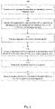
- Methods consistent with the present disclosure may include at least one of the steps illustrated in Fig. 2 , performed in any order.
- a method may include at least two of the steps illustrated in Fig. 2 performed overlapping in time, or even simultaneously.
- embodiments consistent with the present disclosure may include at least one but not all of the steps illustrated in Fig. 2 .
- methods consistent with the present disclosure may include more steps, in addition to at least one of the steps illustrated in Fig. 2 . In some embodiments, one or more steps may be repeated.
- an inlet opening of a respiratory air measuring device is connected to a respiratory hood in step 110.
- a flow generator is connected to a channel portion of the respiratory air measuring device, the channel portion including a flow nozzle oriented in a predetermined position.
- the flow nozzle may be positioned within the channel portion so that the generator air flow coming out of the flow nozzle in conjunction with the size and shape of the channel portion creates a measuring air flow having desired or predetermined air flow mechanics.
- the respiratory hood may then be positioned over or around a patient in step 130.
- a component of the respiratory air of the patient in the respiratory hood is measured by a sensor device having a sensor positioned in the respiratory air measuring device as the patient's respiratory air is drawn out of the hood and flows across or through the sensor.
- the air flowing over or through the sensor may be a mixture of the patient's respiratory air and the room air reflowing into the hood.
- the respiratory hood is removed from the patient.
- the entire sensor device or just a component of the sensor device is removed to allow for easy cleaning of the respiratory air measuring device.
- the sensor device or component of the sensor device may be removed and the rest of the respiratory air measuring device, including the flow nozzle, may be flushed with cleaning fluid or otherwise disinfected to clean the respiratory air measuring device.
- any specific order or hierarchy of blocks in the methods of processes disclosed is an illustration of example approaches. Based upon design or implementation preferences, it is understood that the specific order or hierarchy of blocks in the processes may be rearranged, or that all illustrated blocks be performed. In some implementations, any of the blocks may be performed simultaneously.
Landscapes
- Health & Medical Sciences (AREA)
- Life Sciences & Earth Sciences (AREA)
- General Health & Medical Sciences (AREA)
- Pulmonology (AREA)
- Veterinary Medicine (AREA)
- Public Health (AREA)
- Engineering & Computer Science (AREA)
- Biomedical Technology (AREA)
- Heart & Thoracic Surgery (AREA)
- Animal Behavior & Ethology (AREA)
- Emergency Medicine (AREA)
- Surgery (AREA)
- Molecular Biology (AREA)
- Medical Informatics (AREA)
- Pathology (AREA)
- Biophysics (AREA)
- Physics & Mathematics (AREA)
- Physiology (AREA)
- Anesthesiology (AREA)
- Hematology (AREA)
- Obesity (AREA)
- Toxicology (AREA)
- Business, Economics & Management (AREA)
- Emergency Management (AREA)
- Measurement Of The Respiration, Hearing Ability, Form, And Blood Characteristics Of Living Organisms (AREA)
Claims (15)
- Atemluftmessvorrichtung (1), die folgendes umfasst:eine Einlassöffnung (5);eine Auslassöffnung (7), wobei ein Messluftstrom (2) so gestaltet ist, dass er von der Einlassöffnung zu der Auslassöffnung strömt;einen Verteiler (21), der mit der Auslassöffnung gekoppelt ist, wobei der Verteiler so gestaltet ist, dass er einen aus dem Auslass austretenden Luftstrom breiter gestaltet, so dass der austretende Luftstrom kaum wahrnehmbar ist;einen Konnektor (6), der sich an der Einlassöffnung befindet, wobei der Konnektor so gestaltet ist, dass er die Atemluftmessvorrichtung direkt oder indirekt an einer Verbindungsöffnung (3) einer Abdeckhaube (4) sichert;mindestens eine Sensorvorrichtung (8), die in einer Strömungsrichtung des Messluftstroms stromabwärts der Verbindungsöffnung angeordnet ist, wobei die Sensorvorrichtung so gestaltet ist, dass sie mindestens einen Bestandteil der Atemluft eines Patienten misst;einen Strömungsgenerator (11), der in der Strömungsrichtung des Messluftstroms stromabwärts der Sensorvorrichtung angeordnet ist, wobei der Strömungsgenerator so gestaltet ist, dass er den Messluftstrom in einem Kanalabschnitt (13) mit einem freien Querschnitt zwischen 100 mm2 und 600 mm2 erzeugt, und wobei der Abschnitt zu der Einlassöffnung und der Auslassöffnung offen ist, wobei der Strömungsgenerator folgendes umfasst:eine Luftverbindung (15), die so gestaltet ist, dass sie einen Generatorluftstrom (12) mit einem Überdruck von bis zu 0,5 bar bereitstellt; undmindestens eine Strömungsdüse (14), wobei der Generatorluftstrom so gestaltet ist, dass er aus dieser austritt, wobei die Strömungsdüse so gestaltet ist, dass sie den Generatorluftstrom so beeinflusst, dass der Generatorluftstrom den Messluftstrom erzeugt.
- Atemluftmessvorrichtung nach Anspruch 1,
wobei der Konnektor für eine Befestigung an einer komplementären Verbindungsöffnung an der Abdeckhaube gestaltet ist. - Atemluftmessvorrichtung nach Anspruch 1,
wobei der Konnektor mit einem flexiblen Schlauchabschnitt verbunden ist, der ein von dem Verbindungsmittel entferntes Ende aufweist, mit einer Schlauchverbindung, die für eine Befestigung an einer komplementären Verbindungsöffnung an der Abdeckhaube gestaltet ist. - Atemluftmessvorrichtung nach Anspruch 1,
wobei diese ferner ein einstellbares Druckluftventil umfasst, das direkt oder indirekt an der Luftverbindung angeordnet ist, wobei das Druckluftventil für eine Verbindung mit einer externen Druckluftquelle gestaltet ist. - Atemluftmessvorrichtung nach Anspruch 4,
wobei das Druckluftventil stufenweise oder stufenlos einstellbar ist in Verbindung mit dem Druck oder der Geschwindigkeit des Generatorluftstroms. - Atemluftmessvorrichtung nach Anspruch 1,
wobei diese ferner ein einstellbares Gebläse (18) oder einen Ventilator umfasst, das bzw. der sich direkt oder indirekt an der Luftverbindung befindet. - Atemluftmessvorrichtung nach Anspruch 6,
wobei das Gebläse oder der Ventilator stufenweise oder stufenlos einstellbar ist in Verbindung mit dem Druck oder der Geschwindigkeit des Generatorluftstroms. - Atemluftmessvorrichtung nach Anspruch 1,
wobei sich die Strömungsdüse in der Mitte des Kanalabschnitts befindet, und wobei der Messluftstrom so gestaltet ist, dass er um die Strömungsdüse zirkuliert. - Atemluftmessvorrichtung nach Anspruch 1,
wobei die Strömungsdüse als ein Ringspalt an der Peripherie des Kanalabschnitts gestaltet ist, mit einem Abschnitt mit einem Coanda-Profil, wobei der Messluftstrom so gestaltet ist, dass er dort hindurch strömt. - Atemluftmessvorrichtung nach Anspruch 1,
wobei die Sensorvorrichtung von der Atemluftmessvorrichtung entfernt werden kann. - Atemluftmessvorrichtung nach Anspruch 1,
wobei eine Komponente der Sensorvorrichtung, die sich in Kontakt mit dem Messluftstrom befindet, für einen Austausch als ein Verbrauchsartikel gestaltet ist. - Atemluftmessvorrichtung nach Anspruch 1,
wobei diese ferner eine Volumenstrommessvorrichtung (9) zum Messen des Volumenstroms des Messluftstroms umfasst, angeordnet zwischen der Verbindungsöffnung und dem Strömungsgenerator. - Atemluftmessvorrichtung nach Anspruch 1,
wobei die Atemluftmessvorrichtung für eine Desinfektion oder Sterilisierung nach einem der folgenden gestaltet ist: Entkoppelung der Leitungen, Lösen entfernbarer Bestandteile und Auseinanderbau der Atemluftmessvorrichtung in einzelne Teile. - Atemluftmessvorrichtung nach Anspruch 1,
wobei diese ferner einen Geräuschdämpfer umfasst, der stromabwärts des Strömungsgenerators angeordnet ist, wobei der Geräuschdämpfer so gestaltet ist, dass er den durch den Strömungsgenerator erzeugten Geräusche verringert. - Atemluftmessvorrichtung nach Anspruch 1,
wobei sich ein Bestandteil der Sensorvorrichtung nicht in Kontakt mit dem Messluftstrom befindet und von der Atemluftmessvorrichtung entfernt werden kann.
Applications Claiming Priority (1)
| Application Number | Priority Date | Filing Date | Title |
|---|---|---|---|
| DE102014111528.7A DE102014111528B3 (de) | 2014-08-13 | 2014-08-13 | Atemluftmessvorrichtung |
Publications (2)
| Publication Number | Publication Date |
|---|---|
| EP2997885A1 EP2997885A1 (de) | 2016-03-23 |
| EP2997885B1 true EP2997885B1 (de) | 2022-11-02 |
Family
ID=53264463
Family Applications (1)
| Application Number | Title | Priority Date | Filing Date |
|---|---|---|---|
| EP15166454.7A Active EP2997885B1 (de) | 2014-08-13 | 2015-05-05 | Atemgasmessvorrichtung |
Country Status (4)
| Country | Link |
|---|---|
| US (2) | US10786179B2 (de) |
| EP (1) | EP2997885B1 (de) |
| DE (1) | DE102014111528B3 (de) |
| WO (1) | WO2016023648A1 (de) |
Families Citing this family (7)
| Publication number | Priority date | Publication date | Assignee | Title |
|---|---|---|---|---|
| US11247008B1 (en) | 2020-08-05 | 2022-02-15 | Effortless Oxygen, Llc | Flow triggered gas delivery |
| US11318276B2 (en) | 2020-08-05 | 2022-05-03 | Effortless Oxygen, Llc | Flow triggered gas delivery |
| US11420007B2 (en) | 2020-08-05 | 2022-08-23 | Effortless Oxygen, Llc | Flow triggered gas delivery |
| KR102237857B1 (ko) * | 2020-11-27 | 2021-04-08 | 브레싱스 주식회사 | 살균 소독 기능을 구비하는 슬라이딩 타입의 호흡 측정 장치 |
| KR102237856B1 (ko) * | 2020-11-27 | 2021-04-08 | 브레싱스 주식회사 | 살균 소독 기능을 구비하는 로테이팅 타입의 호흡 측정 장치 |
| KR102459142B1 (ko) * | 2020-11-27 | 2022-10-26 | 브레싱스 주식회사 | 살균 소독 기능을 구비하는 호흡 측정 장치 |
| PL4124292T3 (pl) * | 2021-07-29 | 2025-02-17 | Ndd Medizintechnik Ag | Układ rurek oddechowych do urządzenia do diagnostyki wydolności płuc zawierający dalszy wkład filtracyjny |
Family Cites Families (22)
| Publication number | Priority date | Publication date | Assignee | Title |
|---|---|---|---|---|
| US3586021A (en) * | 1968-11-26 | 1971-06-22 | Bowles Fluidics Corp | Fluidic breathing assistor |
| US4106504A (en) * | 1976-12-06 | 1978-08-15 | The United States Of America As Represented By The Secretary Of The Navy | Portable recompression chamber with air scrubber |
| US4261355A (en) * | 1978-09-25 | 1981-04-14 | Glazener Edwin L | Constant positive pressure breathing apparatus |
| FI78231C (fi) * | 1984-11-21 | 1989-07-10 | Instrumentarium Oy | Maetanordning foer metaboliska storheter anslutbar till en respirator. |
| US4832042A (en) * | 1987-08-19 | 1989-05-23 | Emory University | Ventilator hood system for indirect calorimetry |
| US5081871A (en) * | 1989-02-02 | 1992-01-21 | The United States Of America As Represented By The Secretary Of The Department Of Health And Human Services | Breath sampler |
| FI91358C (fi) * | 1991-04-12 | 1994-06-27 | Instrumentarium Oy | Menetelmä ja laitteisto stabiilin kaasuseoksen syöttämiseksi potilaalle |
| DE4127599A1 (de) * | 1991-08-21 | 1993-02-25 | Fenyves U Gut Deutschland Gmbh | Einrichtung zur ueberwachung der atmung eines patienten |
| JP3325673B2 (ja) * | 1993-10-25 | 2002-09-17 | アークレイ株式会社 | 呼気中の成分濃度補正方法及び呼気分析装置 |
| DE4429561A1 (de) * | 1994-08-19 | 1996-02-22 | Mueller & Sebastiani Elek Gmbh | Lungenfunktionsanalysevorrichtung |
| US6076392A (en) * | 1997-08-18 | 2000-06-20 | Metasensors, Inc. | Method and apparatus for real time gas analysis |
| US6067983A (en) * | 1997-09-19 | 2000-05-30 | Sensormedics Corporation | Method and apparatus for controlled flow sampling from the airway |
| US6629934B2 (en) * | 2000-02-02 | 2003-10-07 | Healthetech, Inc. | Indirect calorimeter for medical applications |
| WO2005117700A1 (en) * | 2004-05-26 | 2005-12-15 | The Regents Of The University Of California | Portable alveolar gas meter |
| ITMI20061540A1 (it) * | 2006-08-02 | 2008-02-03 | Milano Politecnico | Apparato e procedimento a doppia pletismografia corporea per la misura degli spostamenti di sangue tra il comparto toraco-addominale e la periferia corporea |
| US20090156952A1 (en) * | 2007-12-13 | 2009-06-18 | Hunter C Eric | Apparatuses and Methods for Diagnosing and Treating Respiratory Conditions |
| GB0915819D0 (en) * | 2009-09-10 | 2009-10-07 | Smiths Medical Int Ltd | Breathing apparatus |
| US9445748B2 (en) * | 2009-09-30 | 2016-09-20 | Mti Medtech Innovation Gmbh | Device and method for fractionally collecting contents of exhaled air |
| US8453601B2 (en) * | 2011-05-19 | 2013-06-04 | C-Lock Inc. | Vaccine and health-related applications for ruminant breath monitoring system |
| WO2013026902A1 (en) * | 2011-08-23 | 2013-02-28 | Aerocrine Ab | Devices and methods for generating an artificial exhalation profile |
| JP6099249B2 (ja) * | 2011-12-16 | 2017-03-22 | ミナト医科学株式会社 | 呼気ガス分析装置 |
| JP5636555B2 (ja) * | 2012-04-02 | 2014-12-10 | 株式会社メトラン | ポンプユニット、呼吸補助装置 |
-
2014
- 2014-08-13 DE DE102014111528.7A patent/DE102014111528B3/de active Active
-
2015
- 2015-05-05 US US14/704,157 patent/US10786179B2/en active Active
- 2015-05-05 WO PCT/EP2015/059881 patent/WO2016023648A1/en not_active Ceased
- 2015-05-05 EP EP15166454.7A patent/EP2997885B1/de active Active
-
2020
- 2020-08-06 US US16/987,293 patent/US20200359936A1/en not_active Abandoned
Also Published As
| Publication number | Publication date |
|---|---|
| US10786179B2 (en) | 2020-09-29 |
| US20200359936A1 (en) | 2020-11-19 |
| EP2997885A1 (de) | 2016-03-23 |
| US20160045138A1 (en) | 2016-02-18 |
| WO2016023648A1 (en) | 2016-02-18 |
| DE102014111528B3 (de) | 2015-07-09 |
Similar Documents
| Publication | Publication Date | Title |
|---|---|---|
| EP2997885B1 (de) | Atemgasmessvorrichtung | |
| JP6559142B2 (ja) | 人工知能型サクション装置 | |
| US20230226303A1 (en) | System and method for preventing cross-contamination in flow generation systems | |
| EP2903515B1 (de) | Atemmaske | |
| RU2011141706A (ru) | Катетер для струйной вентиляции | |
| JP2012509160A5 (de) | ||
| EP2585152B1 (de) | Ventilation aid, ventilator, system and method for the non-invasive ventilation of premature infants | |
| US20250114548A1 (en) | Measurement device and system for breathing assistance apparatus and/or performing diagnostics | |
| US20170203063A1 (en) | Ventilator-resuscitator device and method of ventilation | |
| KR102075682B1 (ko) | 카테터 가이드 구조체의 위치 조절이 가능한 의료용 석션기 | |
| CN115803075A (zh) | 辅助通气接口的改进 | |
| KR101703428B1 (ko) | 심폐소생술 보조장치 | |
| KR20190029266A (ko) | 수동식 인공호흡기의 소리를 이용한 공기공급량 측정장치 | |
| KR102062781B1 (ko) | 멀티 커넥터 모듈 및 멀티 커넥터 모듈이 구비된 카테터 가이드 구조체 | |
| KR101729027B1 (ko) | 착탈식 카테터 구조체 | |
| KR20260000211A (ko) | 웨어러블 공기살균기 | |
| KR102235677B1 (ko) | 착탈식 카테터 가이드 구조체 | |
| HK40073054A (en) | System for preventing cross-contamination in flow generation systems | |
| KR101635140B1 (ko) | 인공지능형 석션기 | |
| KR20180033039A (ko) | 착탈식 카테터 구조체 | |
| KR20160098919A (ko) | 영유아용 인공호흡기 및 그 제어 방법 |
Legal Events
| Date | Code | Title | Description |
|---|---|---|---|
| PUAI | Public reference made under article 153(3) epc to a published international application that has entered the european phase |
Free format text: ORIGINAL CODE: 0009012 |
|
| AK | Designated contracting states |
Kind code of ref document: A1 Designated state(s): AL AT BE BG CH CY CZ DE DK EE ES FI FR GB GR HR HU IE IS IT LI LT LU LV MC MK MT NL NO PL PT RO RS SE SI SK SM TR |
|
| AX | Request for extension of the european patent |
Extension state: BA ME |
|
| 17P | Request for examination filed |
Effective date: 20160920 |
|
| RBV | Designated contracting states (corrected) |
Designated state(s): AL AT BE BG CH CY CZ DE DK EE ES FI FR GB GR HR HU IE IS IT LI LT LU LV MC MK MT NL NO PL PT RO RS SE SI SK SM TR |
|
| STAA | Information on the status of an ep patent application or granted ep patent |
Free format text: STATUS: EXAMINATION IS IN PROGRESS |
|
| 17Q | First examination report despatched |
Effective date: 20170801 |
|
| GRAP | Despatch of communication of intention to grant a patent |
Free format text: ORIGINAL CODE: EPIDOSNIGR1 |
|
| STAA | Information on the status of an ep patent application or granted ep patent |
Free format text: STATUS: GRANT OF PATENT IS INTENDED |
|
| INTG | Intention to grant announced |
Effective date: 20220620 |
|
| GRAS | Grant fee paid |
Free format text: ORIGINAL CODE: EPIDOSNIGR3 |
|
| GRAA | (expected) grant |
Free format text: ORIGINAL CODE: 0009210 |
|
| STAA | Information on the status of an ep patent application or granted ep patent |
Free format text: STATUS: THE PATENT HAS BEEN GRANTED |
|
| AK | Designated contracting states |
Kind code of ref document: B1 Designated state(s): AL AT BE BG CH CY CZ DE DK EE ES FI FR GB GR HR HU IE IS IT LI LT LU LV MC MK MT NL NO PL PT RO RS SE SI SK SM TR |
|
| REG | Reference to a national code |
Ref country code: GB Ref legal event code: FG4D |
|
| REG | Reference to a national code |
Ref country code: CH Ref legal event code: EP Ref country code: AT Ref legal event code: REF Ref document number: 1528153 Country of ref document: AT Kind code of ref document: T Effective date: 20221115 |
|
| REG | Reference to a national code |
Ref country code: DE Ref legal event code: R096 Ref document number: 602015081393 Country of ref document: DE |
|
| REG | Reference to a national code |
Ref country code: IE Ref legal event code: FG4D |
|
| REG | Reference to a national code |
Ref country code: LT Ref legal event code: MG9D |
|
| REG | Reference to a national code |
Ref country code: NL Ref legal event code: MP Effective date: 20221102 |
|
| REG | Reference to a national code |
Ref country code: AT Ref legal event code: MK05 Ref document number: 1528153 Country of ref document: AT Kind code of ref document: T Effective date: 20221102 |
|
| PG25 | Lapsed in a contracting state [announced via postgrant information from national office to epo] |
Ref country code: SE Free format text: LAPSE BECAUSE OF FAILURE TO SUBMIT A TRANSLATION OF THE DESCRIPTION OR TO PAY THE FEE WITHIN THE PRESCRIBED TIME-LIMIT Effective date: 20221102 Ref country code: PT Free format text: LAPSE BECAUSE OF FAILURE TO SUBMIT A TRANSLATION OF THE DESCRIPTION OR TO PAY THE FEE WITHIN THE PRESCRIBED TIME-LIMIT Effective date: 20230302 Ref country code: NO Free format text: LAPSE BECAUSE OF FAILURE TO SUBMIT A TRANSLATION OF THE DESCRIPTION OR TO PAY THE FEE WITHIN THE PRESCRIBED TIME-LIMIT Effective date: 20230202 Ref country code: LT Free format text: LAPSE BECAUSE OF FAILURE TO SUBMIT A TRANSLATION OF THE DESCRIPTION OR TO PAY THE FEE WITHIN THE PRESCRIBED TIME-LIMIT Effective date: 20221102 Ref country code: FI Free format text: LAPSE BECAUSE OF FAILURE TO SUBMIT A TRANSLATION OF THE DESCRIPTION OR TO PAY THE FEE WITHIN THE PRESCRIBED TIME-LIMIT Effective date: 20221102 Ref country code: ES Free format text: LAPSE BECAUSE OF FAILURE TO SUBMIT A TRANSLATION OF THE DESCRIPTION OR TO PAY THE FEE WITHIN THE PRESCRIBED TIME-LIMIT Effective date: 20221102 Ref country code: AT Free format text: LAPSE BECAUSE OF FAILURE TO SUBMIT A TRANSLATION OF THE DESCRIPTION OR TO PAY THE FEE WITHIN THE PRESCRIBED TIME-LIMIT Effective date: 20221102 |
|
| PG25 | Lapsed in a contracting state [announced via postgrant information from national office to epo] |
Ref country code: RS Free format text: LAPSE BECAUSE OF FAILURE TO SUBMIT A TRANSLATION OF THE DESCRIPTION OR TO PAY THE FEE WITHIN THE PRESCRIBED TIME-LIMIT Effective date: 20221102 Ref country code: PL Free format text: LAPSE BECAUSE OF FAILURE TO SUBMIT A TRANSLATION OF THE DESCRIPTION OR TO PAY THE FEE WITHIN THE PRESCRIBED TIME-LIMIT Effective date: 20221102 Ref country code: LV Free format text: LAPSE BECAUSE OF FAILURE TO SUBMIT A TRANSLATION OF THE DESCRIPTION OR TO PAY THE FEE WITHIN THE PRESCRIBED TIME-LIMIT Effective date: 20221102 Ref country code: IS Free format text: LAPSE BECAUSE OF FAILURE TO SUBMIT A TRANSLATION OF THE DESCRIPTION OR TO PAY THE FEE WITHIN THE PRESCRIBED TIME-LIMIT Effective date: 20230302 Ref country code: HR Free format text: LAPSE BECAUSE OF FAILURE TO SUBMIT A TRANSLATION OF THE DESCRIPTION OR TO PAY THE FEE WITHIN THE PRESCRIBED TIME-LIMIT Effective date: 20221102 Ref country code: GR Free format text: LAPSE BECAUSE OF FAILURE TO SUBMIT A TRANSLATION OF THE DESCRIPTION OR TO PAY THE FEE WITHIN THE PRESCRIBED TIME-LIMIT Effective date: 20230203 |
|
| P01 | Opt-out of the competence of the unified patent court (upc) registered |
Effective date: 20230519 |
|
| PG25 | Lapsed in a contracting state [announced via postgrant information from national office to epo] |
Ref country code: NL Free format text: LAPSE BECAUSE OF FAILURE TO SUBMIT A TRANSLATION OF THE DESCRIPTION OR TO PAY THE FEE WITHIN THE PRESCRIBED TIME-LIMIT Effective date: 20221102 |
|
| PG25 | Lapsed in a contracting state [announced via postgrant information from national office to epo] |
Ref country code: SM Free format text: LAPSE BECAUSE OF FAILURE TO SUBMIT A TRANSLATION OF THE DESCRIPTION OR TO PAY THE FEE WITHIN THE PRESCRIBED TIME-LIMIT Effective date: 20221102 Ref country code: RO Free format text: LAPSE BECAUSE OF FAILURE TO SUBMIT A TRANSLATION OF THE DESCRIPTION OR TO PAY THE FEE WITHIN THE PRESCRIBED TIME-LIMIT Effective date: 20221102 Ref country code: EE Free format text: LAPSE BECAUSE OF FAILURE TO SUBMIT A TRANSLATION OF THE DESCRIPTION OR TO PAY THE FEE WITHIN THE PRESCRIBED TIME-LIMIT Effective date: 20221102 Ref country code: DK Free format text: LAPSE BECAUSE OF FAILURE TO SUBMIT A TRANSLATION OF THE DESCRIPTION OR TO PAY THE FEE WITHIN THE PRESCRIBED TIME-LIMIT Effective date: 20221102 Ref country code: CZ Free format text: LAPSE BECAUSE OF FAILURE TO SUBMIT A TRANSLATION OF THE DESCRIPTION OR TO PAY THE FEE WITHIN THE PRESCRIBED TIME-LIMIT Effective date: 20221102 |
|
| REG | Reference to a national code |
Ref country code: DE Ref legal event code: R097 Ref document number: 602015081393 Country of ref document: DE |
|
| PG25 | Lapsed in a contracting state [announced via postgrant information from national office to epo] |
Ref country code: SK Free format text: LAPSE BECAUSE OF FAILURE TO SUBMIT A TRANSLATION OF THE DESCRIPTION OR TO PAY THE FEE WITHIN THE PRESCRIBED TIME-LIMIT Effective date: 20221102 Ref country code: AL Free format text: LAPSE BECAUSE OF FAILURE TO SUBMIT A TRANSLATION OF THE DESCRIPTION OR TO PAY THE FEE WITHIN THE PRESCRIBED TIME-LIMIT Effective date: 20221102 |
|
| PLBE | No opposition filed within time limit |
Free format text: ORIGINAL CODE: 0009261 |
|
| STAA | Information on the status of an ep patent application or granted ep patent |
Free format text: STATUS: NO OPPOSITION FILED WITHIN TIME LIMIT |
|
| 26N | No opposition filed |
Effective date: 20230803 |
|
| PG25 | Lapsed in a contracting state [announced via postgrant information from national office to epo] |
Ref country code: SI Free format text: LAPSE BECAUSE OF FAILURE TO SUBMIT A TRANSLATION OF THE DESCRIPTION OR TO PAY THE FEE WITHIN THE PRESCRIBED TIME-LIMIT Effective date: 20221102 |
|
| REG | Reference to a national code |
Ref country code: CH Ref legal event code: PL |
|
| PG25 | Lapsed in a contracting state [announced via postgrant information from national office to epo] |
Ref country code: MC Free format text: LAPSE BECAUSE OF FAILURE TO SUBMIT A TRANSLATION OF THE DESCRIPTION OR TO PAY THE FEE WITHIN THE PRESCRIBED TIME-LIMIT Effective date: 20221102 |
|
| REG | Reference to a national code |
Ref country code: BE Ref legal event code: MM Effective date: 20230531 |
|
| PG25 | Lapsed in a contracting state [announced via postgrant information from national office to epo] |
Ref country code: MC Free format text: LAPSE BECAUSE OF FAILURE TO SUBMIT A TRANSLATION OF THE DESCRIPTION OR TO PAY THE FEE WITHIN THE PRESCRIBED TIME-LIMIT Effective date: 20221102 Ref country code: LU Free format text: LAPSE BECAUSE OF NON-PAYMENT OF DUE FEES Effective date: 20230505 Ref country code: LI Free format text: LAPSE BECAUSE OF NON-PAYMENT OF DUE FEES Effective date: 20230531 Ref country code: CH Free format text: LAPSE BECAUSE OF NON-PAYMENT OF DUE FEES Effective date: 20230531 |
|
| REG | Reference to a national code |
Ref country code: IE Ref legal event code: MM4A |
|
| PG25 | Lapsed in a contracting state [announced via postgrant information from national office to epo] |
Ref country code: IE Free format text: LAPSE BECAUSE OF NON-PAYMENT OF DUE FEES Effective date: 20230505 |
|
| PG25 | Lapsed in a contracting state [announced via postgrant information from national office to epo] |
Ref country code: IE Free format text: LAPSE BECAUSE OF NON-PAYMENT OF DUE FEES Effective date: 20230505 |
|
| PG25 | Lapsed in a contracting state [announced via postgrant information from national office to epo] |
Ref country code: IT Free format text: LAPSE BECAUSE OF FAILURE TO SUBMIT A TRANSLATION OF THE DESCRIPTION OR TO PAY THE FEE WITHIN THE PRESCRIBED TIME-LIMIT Effective date: 20221102 Ref country code: BE Free format text: LAPSE BECAUSE OF NON-PAYMENT OF DUE FEES Effective date: 20230531 |
|
| PGFP | Annual fee paid to national office [announced via postgrant information from national office to epo] |
Ref country code: GB Payment date: 20240521 Year of fee payment: 10 |
|
| PGFP | Annual fee paid to national office [announced via postgrant information from national office to epo] |
Ref country code: DE Payment date: 20240529 Year of fee payment: 10 |
|
| PGFP | Annual fee paid to national office [announced via postgrant information from national office to epo] |
Ref country code: FR Payment date: 20240527 Year of fee payment: 10 |
|
| PG25 | Lapsed in a contracting state [announced via postgrant information from national office to epo] |
Ref country code: BG Free format text: LAPSE BECAUSE OF FAILURE TO SUBMIT A TRANSLATION OF THE DESCRIPTION OR TO PAY THE FEE WITHIN THE PRESCRIBED TIME-LIMIT Effective date: 20221102 |
|
| PG25 | Lapsed in a contracting state [announced via postgrant information from national office to epo] |
Ref country code: BG Free format text: LAPSE BECAUSE OF FAILURE TO SUBMIT A TRANSLATION OF THE DESCRIPTION OR TO PAY THE FEE WITHIN THE PRESCRIBED TIME-LIMIT Effective date: 20221102 |
|
| PG25 | Lapsed in a contracting state [announced via postgrant information from national office to epo] |
Ref country code: CY Free format text: LAPSE BECAUSE OF FAILURE TO SUBMIT A TRANSLATION OF THE DESCRIPTION OR TO PAY THE FEE WITHIN THE PRESCRIBED TIME-LIMIT; INVALID AB INITIO Effective date: 20150505 |
|
| PG25 | Lapsed in a contracting state [announced via postgrant information from national office to epo] |
Ref country code: HU Free format text: LAPSE BECAUSE OF FAILURE TO SUBMIT A TRANSLATION OF THE DESCRIPTION OR TO PAY THE FEE WITHIN THE PRESCRIBED TIME-LIMIT; INVALID AB INITIO Effective date: 20150505 |
|
| REG | Reference to a national code |
Ref country code: DE Ref legal event code: R119 Ref document number: 602015081393 Country of ref document: DE |
|
| PG25 | Lapsed in a contracting state [announced via postgrant information from national office to epo] |
Ref country code: TR Free format text: LAPSE BECAUSE OF FAILURE TO SUBMIT A TRANSLATION OF THE DESCRIPTION OR TO PAY THE FEE WITHIN THE PRESCRIBED TIME-LIMIT Effective date: 20221102 |
|
| GBPC | Gb: european patent ceased through non-payment of renewal fee |
Effective date: 20250505 |
|
| PG25 | Lapsed in a contracting state [announced via postgrant information from national office to epo] |
Ref country code: GB Free format text: LAPSE BECAUSE OF NON-PAYMENT OF DUE FEES Effective date: 20250505 |
|
| PG25 | Lapsed in a contracting state [announced via postgrant information from national office to epo] |
Ref country code: DE Free format text: LAPSE BECAUSE OF NON-PAYMENT OF DUE FEES Effective date: 20251202 |
|
| PG25 | Lapsed in a contracting state [announced via postgrant information from national office to epo] |
Ref country code: FR Free format text: LAPSE BECAUSE OF NON-PAYMENT OF DUE FEES Effective date: 20250531 |