EP2997303B1 - Gehäuse zur sicherung einer eingelassenen befestigung - Google Patents
Gehäuse zur sicherung einer eingelassenen befestigung Download PDFInfo
- Publication number
- EP2997303B1 EP2997303B1 EP14719012.8A EP14719012A EP2997303B1 EP 2997303 B1 EP2997303 B1 EP 2997303B1 EP 14719012 A EP14719012 A EP 14719012A EP 2997303 B1 EP2997303 B1 EP 2997303B1
- Authority
- EP
- European Patent Office
- Prior art keywords
- housing
- side wall
- spring
- springs
- support
- Prior art date
- Legal status (The legal status is an assumption and is not a legal conclusion. Google has not performed a legal analysis and makes no representation as to the accuracy of the status listed.)
- Not-in-force
Links
Images

Classifications
-
- F—MECHANICAL ENGINEERING; LIGHTING; HEATING; WEAPONS; BLASTING
- F21—LIGHTING
- F21V—FUNCTIONAL FEATURES OR DETAILS OF LIGHTING DEVICES OR SYSTEMS THEREOF; STRUCTURAL COMBINATIONS OF LIGHTING DEVICES WITH OTHER ARTICLES, NOT OTHERWISE PROVIDED FOR
- F21V21/00—Supporting, suspending, or attaching arrangements for lighting devices; Hand grips
- F21V21/02—Wall, ceiling, or floor bases; Fixing pendants or arms to the bases
- F21V21/04—Recessed bases
- F21V21/047—Mounting arrangements with fastening means engaging the inner surface of a hole in a ceiling or wall, e.g. for solid walls or for blind holes
-
- F—MECHANICAL ENGINEERING; LIGHTING; HEATING; WEAPONS; BLASTING
- F21—LIGHTING
- F21S—NON-PORTABLE LIGHTING DEVICES; SYSTEMS THEREOF; VEHICLE LIGHTING DEVICES SPECIALLY ADAPTED FOR VEHICLE EXTERIORS
- F21S8/00—Lighting devices intended for fixed installation
- F21S8/02—Lighting devices intended for fixed installation of recess-mounted type, e.g. downlighters
-
- F—MECHANICAL ENGINEERING; LIGHTING; HEATING; WEAPONS; BLASTING
- F21—LIGHTING
- F21V—FUNCTIONAL FEATURES OR DETAILS OF LIGHTING DEVICES OR SYSTEMS THEREOF; STRUCTURAL COMBINATIONS OF LIGHTING DEVICES WITH OTHER ARTICLES, NOT OTHERWISE PROVIDED FOR
- F21V21/00—Supporting, suspending, or attaching arrangements for lighting devices; Hand grips
- F21V21/02—Wall, ceiling, or floor bases; Fixing pendants or arms to the bases
- F21V21/04—Recessed bases
- F21V21/041—Mounting arrangements specially adapted for false ceiling panels or partition walls made of plates
- F21V21/042—Mounting arrangements specially adapted for false ceiling panels or partition walls made of plates using clamping means, e.g. for clamping with panel or wall
- F21V21/044—Mounting arrangements specially adapted for false ceiling panels or partition walls made of plates using clamping means, e.g. for clamping with panel or wall with elastically deformable elements, e.g. spring tongues
Definitions
- the current invention relates to a housing for securing a recessed fixture, for instance a recessed lighting fixture, notably in a structure such as a ceiling or wall, comprising a hole.
- a recessed fixture typically comprises a housing, usually essentially of cylindrical shape, receiving a light-emitting element such as for example an incandescent light bulb, or compact fluorescent light, or led emitting diode module.
- the housing is usually designed so as to be at least partially inserted in a support, such as a ceiling or a wall, through a hole.
- European patent published under the reference EP 1016819 discloses a fixture consisting of two legs fastened on a can housing in such a way that they can pivot around the fixing point on the housing.
- This housing has a flange which is able to lean on the outside surface of the support. The legs are held by springs so that they can put pressure on the inside surface of the support. The support is then maintained between the legs and the housing's flange.
- Some other known fixtures have many fastening parts and springs so that when the housing can is inserted into the hole in the support, the fastening parts expand out of the housing to put pressure on the inside surface of the support.
- such fixtures use systems like screws or clips which have to be manually operated by an operator, for example an installer.
- Installation time directly correlates to the installation costs and usually derives from the high complexity of the installation.
- JP S62 4018 U discloses a recessed fixture allowing easy insertion in the ceiling by an installer.
- One drawback of the fixture described in this utility model is that extraction of the recessed fixture is uneasy.
- JP S48 1930 Y1 discloses a recessed fixture with a sliding clip allowing automated installation of the fixture in the ceiling.
- One aim of the present invention is to palliate at least the above mentioned drawbacks.
- the present invention enables a quicker and easier installation and removal of a light fixture by an operator or installer using only one hand, and allows many reinstallations of the fixture, while requiring a much smaller built-in height, compared to known fixtures.
- the current invention proposes a housing for securing a recessed fixture in a support, the housing comprising at least one spring resting on a portion of the side wall when loaded, and extending outwardly from the side wall when released so as to secure the housing in the support; the housing further comprises a releasable retention member keeping the spring loaded over a given length of insertion of the housing into the support.
- the support typically comprises a hole
- the housing can comprise a side wall configured to be at least partly inserted through the hole, the housing further comprising at least one spring attached to the side wall, wherein the spring is configured for resting on a portion of the side wall when loaded, and for extending outwardly from the side wall when released so as to secure the housing in the support, the housing further comprising at least one retention member configured for keeping the spring loaded as long as the length of the side wall that has been inserted through the hole is smaller than a determined length, and for releasing the spring when the length of the side wall that has been inserted through the hole reaches the determined length.
- the side wall is formed by a rim of essentially cylindrical shape, and the retention member can be formed by at least one sliding element configured for being slid substantially along the surface of the side wall as the housing is being inserted through the hole.
- Each sliding element is formed by a clip comprising a leg configured for leaning on a surface of the support as the housing is inserted through the hole.
- the housing can comprise a shoulder designed to rest on a surface of the support when the housing is fully inserted, and each leg can be configured to lean on the shoulder when the housing is fully inserted.
- each clip can comprise a horizontal groove configured for retaining one of said springs.
- the side wall comprises a plurality of side wall sections separated by gaps, a gap being defined by the respective edges of two adjacent side wall sections, each clip being configured for sliding on two adjacent side wall sections.
- each clip can comprise a sliding member configured to be led along the corresponding edges of adjacent side wall sections forming leading surfaces.
- the sliding member can be formed by grooves in the lateral edges of the clip.
- each spring can have a shape designed to allow releasing the mounting through rotating the housing.
- each spring can be a beveled spring formed by an elongated blade having an essentially triangular shape, comprising at least one first end with a smaller height and one second end with a larger end, the housing comprising attachment means for attaching said second end to the side wall.
- the attachment means can be formed by spring attachment means on the surface of the side wall comprising grooves configured to be mated with corresponding notches realized on the springs in the region of said second end.
- the springs or the clips can be made of steel or of a plastic material.
- Another aspect of the current invention is a recessed light fixture comprising a housing as per any of the described embodiments.
- Figure 1 presents a perspective view illustrating a housing following an exemplary embodiment of the invention.
- a housing 1 can have an overall shape similar to that of a typical housing comprised in a fixture for a lighting spot, to be installed in a ceiling for instance.
- the housing 1 has an essentially cylindrical shape, and can comprise a housing body 10 comprising a side wall 10a of cylindrical or conical shape, the housing body 10 having a lower base that can comprise a shoulder 10b, designed for resting on a support when the housing 1 is properly positioned therein, once fully inserted in the support through a hole.
- the housing 1 can further comprise connection members, such as a socket, for allowing attaching a light-emitting element, such as a light bulb, these elements being not illustrated in the figures.
- the side wall 10a can for example be formed by a rim with an essentially cylindrical shape.
- a plurality of springs 12 can be attached to the side wall 10a, by means of adequate attachment means.
- at least two springs can be used.
- three springs 12 are used.
- the springs 12 can have an elongated shape and can be designed so as to rest on the outer surface of the side wall 10a when they are loaded, by winding round the external surface of the side wall 10a, and further designed to extend radially outwardly from the outer surface of the side wall 10a when they are released.
- the springs 12 can be manually loaded by an operator, and/or loaded during the assembly process of the housing 1. Each spring 12 can be kept loaded by means of a retention member 14.
- the retention member 14 can be formed by a sliding element, for example a clip 140.
- the housing can comprise as many clips 140 as there are springs 12.
- the clips 140 are designed to be able to be slid along the side wall 10a parallel to the side wall 10a main axis.
- each clip 140 can comprise a horizontal leg 142 configured in such a way that it can lean on the outside surface of the support when the fixture comprising the housing 1 is moved up inserted into the hole in the support, as illustrated in Figures 2A to 2C described hereinafter.
- a clip 140 can be designed so that its overall shape essentially moulds the shape of the external surface of the side wall 10a, while a horizontal leg 142 can be designed to essentially extend outwardly from the side wall 10a.
- the retention member 14 can be formed by a rotating element, for example designed to be rotated around an axis that is perpendicular to the main symmetry axis of the housing 1.
- the rotating element can comprise attachment means for being attached to the side wall 10a while being able to be rotated around the axis, thus forming a pivot linkage.
- the rotating element can have an essentially elongated shape, and can comprise at a first extremity a horizontal leg, configured in such a way that it can lean on the outside surface of the support when the fixture comprising the housing 1 is moved up inserted into the hole in the support, in a way similar to the leg 142 described above.
- the rotating element may possibly further comprise a second extremity having a shape that allows retaining the spring 12.
- the leg can be protruding outwardly in reference to the external surface of the housing 1, and the shape of the second extremity can be designed to protrude inwardly in reference to the external surface of the housing 1.
- the rotation axis of the rotating element can preferably be located closer to the first extremity than to the second extremity of the rotating element, in order to increase the sensitivity of releasing the spring 12 thanks to the lever arm effect, the travel of the first extremity being thus smaller than that of the second extremity of the rotating element.
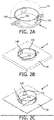
- FIGS 2A to 2C show perspective views illustrating a housing 1 as described below in reference to Figure 1 , at different phases during installation in a support 20, by insertion through a hole 202.
- the support 20 is a ceiling, only one part thereof being represented.
- the shape of the springs 12, and the thickness thereof, can be configured in a way that the springs 12 do not protrude significantly when in retained configuration, so as not to hamper the insertion of the housing 1 through the hole 202.
- the hole 202 in the support 20 has a shape that is adapted to the shape of the housing 1, for example a round shape, and the hole 202 diameter is large enough for the clips 140 to be able to pass through, but smaller than the external diameter of the shoulder 10b, so as to prevent the fixture to entirely pass through the support 20, and smaller than the diameter around the legs 142 so that the legs 142 can lean on the outside surface of the support 20 when the fixture comprising the housing 1 is moved up inserted into the hole 202.
- the housing 1 can be further designed so that the legs 142 lean on the upper surface of the shoulder 10b, once the housing 1 has been fully inserted in the support 20 through the hole 202.
- the springs 12 are configured for resting on a portion of the side wall 10a when loaded, and for extending outwardly from the side wall 10a when released so as to secure the housing 1 in the support 20, the retention members being configured for keeping the springs 12 loaded as long as the length of the side wall 10a that has been inserted through the hole 202 is smaller than a determined length, and for releasing the springs 12 when the length of the side wall 10a that has been inserted through the hole 202 reaches the determined length.
- the springs 12 can be bevelled, for example by being formed with an elongated-shape triangular blade.
- bevelled springs allow compensating for various thicknesses of the support 20: however thick the support may be, a bevelled spring always allows that pressure be put on the internal side thereof, therefore keeping the fixture comprising the housing 1 properly positioned in its intended support.
- bevelled springs allow easy removal of the housing 1, simply by rotating it clockwise or counter-clockwise, depending on the shape of the springs 12.
- a housing 1 comprising bevelled springs 12, simply using one hand for holding the shoulder 10b and rotating the housing 1 in the appropriate direction; if the housing 1 is part of a spot light fixture to be mounted in a ceiling, then it will drop down by itself due to its weight.
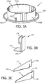
- FIG. 3A presents a detailed structure of a housing body as in an exemplary embodiment of the invention
- Figure 3C presents a detailed structure of springs, as in an exemplary embodiment of the invention.
- FIG. 3A illustrates a housing body of a housing as described below in reference to Figures 1 and 2A to 2C .
- a housing body 300 basically comprises a side wall 310a.
- the side wall 310a is formed by three side wall sections 310a1, 310a2, 310a3, separated by gaps.
- a gap is delimited by two respective edges of adjacent side wall sections 310a1, 310a2, 310a3, the edges of the adjacent side wall sections 310a1, 310a2, 310a3 being defining rails allowing sliding the sliding elements along the side wall 310a.
- a sliding element can be formed by a clip 140 as illustrated in Figure 3B .
- the side wall sections 310a1, 310a2, 310a3 can further comprise spring attachment means 32 allowing fastening the springs 12 to the housing, as described above.
- the spring attachments means 32 can be formed by protruding elements with a T-shaped section, thus providing grooves able to be mated with corresponding notches realized on the springs, as described hereinafter in reference to Figure 3C .
- Various attachment means can also be used, such as rivets, clips, hooks, glue, soldering for example.
- a clip 140 may essentially have the global shape of an "L", the basis of the clip 140 being forming the leg 142 as described above in reference to Figure 1 .
- the lateral edges, or vertical edges in the illustrated example, of the clip 140 can comprise a sliding member, for example formed by vertical grooves 144 that can be led along the leading surfaces that are formed by the edges of adjacent side wall sections 310a1, 310a2, 310a3 as defined above in reference to Figure 3A .
- vertical grooves may be formed at the edges of adjacent side wall sections 310a1, 310a2, 310a3, in such a configuration the clip 140 may not comprise vertical grooves.
- the clip 140 further comprises a horizontal groove 146, in its upper part, configured for retaining the springs 12.
- the springs 12 can be formed with an elongated-shape triangular blade according to a preferred embodiment as described above, i.e. having at least one first end 12a with a smaller height designed for allowing retaining the springs 12, for instance by resting in the horizontal groove 146, and one second end 12b with a larger height.
- the second end 12b can possibly comprise notches 120, for allowing fastening the spring 12 to attachment means 32 comprised in the housing body 300, as described above in reference to Figure 3A .
- the springs 12, as well as the clips 140 and housing body 300 can for instance be made of steel; they can also be made of a plastic material.
- the illustrated embodiments relate to fixtures for lighting spots, in a support such as a ceiling. Similar structures may for instance also apply to wall fixtures for electrical switches or mains sockets.
Landscapes
- Engineering & Computer Science (AREA)
- General Engineering & Computer Science (AREA)
- Non-Portable Lighting Devices Or Systems Thereof (AREA)
- Clamps And Clips (AREA)
- Insertion Pins And Rivets (AREA)
Claims (11)
- Gehäuse (10) zur Sicherung einer eingelassenen Befestigung in einer Halterung (20), ein Loch (202) umfassend, wobei das Gehäuse (10) umfasst:- eine Seitenwand (10a), die konfiguriert ist, um zumindest teilweise durch das Loch (202) hindurch eingesetzt zu werden,- zumindest eine Feder (12), die an der Seitenwand (10a) angebracht ist,wobei die Feder (12) konfiguriert ist, um sich an einem Abschnitt der Seitenwand (10a) herumwickelnd anzulegen, wenn sie belastet ist, und um sich von der Seitenwand (10a) nach außen zu erstrecken, wenn sie gelöst ist, um das Gehäuse (10) in der Halterung (20) zu sichern, wobei das Gehäuse (10) darüber hinaus ein Rückhalteelement umfasst, um die Feder (12) belastet zu halten, solange eine Länge der Seitenwand (10a), die durch das Loch (202) hindurch eingesetzt ist, kleiner ist, als eine bestimmte Länge, und um die Feder (12) zu lösen, wenn die Länge der Seitenwand (10a), die durch das Loch (202) hindurch eingesetzt ist die bestimmte Länge erreicht;
wobei die Seitenwand (10a) durch einen Rand mit einer im Wesentlichen zylindrischen Form gebildet wird, das besagte Rückhalteelement durch zumindest ein Gleitelement gebildet wird, das konfiguriert ist, um entlang der Oberfläche der Seitenwand (10a) parallel zur Hauptachse der Seitenwand (10a) verschoben zu werden, wenn das Gehäuse durch das Loch (202) hindurch eingesetzt wird,
wobei jedes Gleitelement durch einen Clip (140) gebildet wird, der einen Schenkel (142) umfasst, konfiguriert, um sich an einer Oberfläche der Halterung (20) abzustützen, wenn das Gehäuse (10) durch das Loch (202) hindurch eingesetzt wird, und
wobei die Seitenwand (10a) eine Vielzahl von Seitenwandabschnitten (310a1, 310a2, 310a3) umfasst, die durch Spalte getrennt sind, wobei ein Spalt durch die jeweiligen Kanten von zwei angrenzenden Seitenwandabschnitten (310a1, 310a2, 310a3) definiert wird, wobei jeder Clip (140) konfiguriert ist, um sich auf zwei angrenzenden Seitenwandabschnitten (310a1, 310a2, 310a3) zu verschieben. - Gehäuse (10) nach Anspruch 1, einen Bund (10b) umfassend, der gestaltet ist, um auf einer Oberfläche der Halterung (20) zu verbleiben, wenn das Gehäuse (10) vollständig eingesetzt ist, und wobei jeder Schenkel (142) konfiguriert ist, um sich am Bund abzustützen, wenn das das Gehäuse (10) vollständig eingesetzt ist.
- Gehäuse (10) nach Anspruch 2, wobei der Clip (140) eine horizontale Nut (146) umfasst, die konfiguriert ist, um eine der besagten Federn (12) zurückzuhalten.
- Gehäuse (10) nach Anspruch 1, wobei jeder Clip (140) ein Gleitelement umfasst, das konfiguriert ist, um entlang der entsprechenden Kanten von angrenzenden Seitenwandabschnitten (310a1, 310a2, 310a3) geführt zu werden, Vorderflächen bildend.
- Gehäuse (10) nach Anspruch 4, wobei das besagte Gleitelement durch Nuten (144) in den Seitenkanten des Clips (140) gebildet wird.
- Gehäuse (10) nach irgendeinem der vorhergehenden Ansprüche, wobei jede Feder (12) eine Form aufweist, die gestaltet ist, um das Lösen der Befestigung durch Drehen des Gehäuses (10) zu ermöglichen.
- Gehäuse (10) nach Anspruch 6, wobei jede Feder (12) eine abgeschrägte Feder ist, die durch eine längliche Lamelle gebildet wird, die eine im Wesentlichen dreieckige Form aufweist, zumindest ein erstes Ende (12a) mit einer geringeren Höhe umfassend, und ein zweites Ende (12b) mit einem breiteren Ende, wobei das Gehäuse (10) Anbringungsmittel zum Anbringen des besagten zweiten Endes (12b) an der Seitenwand (10a) umfasst.
- Gehäuse (10) nach Anspruch 7, wobei die besagten Anbringungsmittel durch Federanbringungsmittel (32) an der Oberfläche der Seitenwand (10a) gebildet werden, Nuten umfassend, die konfiguriert sind, um zu entsprechenden Kerben (120) zu passen, die auf den Federn (12) in der Region des besagten zweiten Endes (12b) ausgeführt sind.
- Gehäuse (10) nach irgendeinem der vorhergehenden Ansprüche, wobei die besagten Federn (12) aus Stahl gefertigt sind.
- Gehäuse (10) nach irgendeinem der Ansprüche 1 bis 8, wobei die besagten Federn (12) aus einem Kunststoffmaterial gefertigt sind.
- Eingelassene Lichtbefestigung, ein Gehäuse (10) nach irgendeinem der vorhergehenden Ansprüche umfassend.
Priority Applications (2)
| Application Number | Priority Date | Filing Date | Title |
|---|---|---|---|
| EP14719012.8A EP2997303B1 (de) | 2013-05-14 | 2014-04-24 | Gehäuse zur sicherung einer eingelassenen befestigung |
| PL14719012T PL2997303T3 (pl) | 2013-05-14 | 2014-04-24 | Obudowa do zabezpieczania zagłębionej oprawy |
Applications Claiming Priority (3)
| Application Number | Priority Date | Filing Date | Title |
|---|---|---|---|
| EP13305608 | 2013-05-14 | ||
| EP14719012.8A EP2997303B1 (de) | 2013-05-14 | 2014-04-24 | Gehäuse zur sicherung einer eingelassenen befestigung |
| PCT/EP2014/058309 WO2014183968A1 (en) | 2013-05-14 | 2014-04-24 | Housing for securing a recessed fixture. |
Publications (2)
| Publication Number | Publication Date |
|---|---|
| EP2997303A1 EP2997303A1 (de) | 2016-03-23 |
| EP2997303B1 true EP2997303B1 (de) | 2017-06-28 |
Family
ID=48539067
Family Applications (1)
| Application Number | Title | Priority Date | Filing Date |
|---|---|---|---|
| EP14719012.8A Not-in-force EP2997303B1 (de) | 2013-05-14 | 2014-04-24 | Gehäuse zur sicherung einer eingelassenen befestigung |
Country Status (6)
| Country | Link |
|---|---|
| US (1) | US10247394B2 (de) |
| EP (1) | EP2997303B1 (de) |
| CN (1) | CN105229375B (de) |
| ES (1) | ES2641043T3 (de) |
| PL (1) | PL2997303T3 (de) |
| WO (1) | WO2014183968A1 (de) |
Families Citing this family (12)
| Publication number | Priority date | Publication date | Assignee | Title |
|---|---|---|---|---|
| USD843642S1 (en) * | 2015-05-03 | 2019-03-19 | Lucifer Lighting Company | Cylindrical fixture mount |
| DK3356727T3 (da) | 2015-09-28 | 2019-09-16 | Fischer Lighting Aps | Lampehus med en låseindretning |
| US10203076B2 (en) | 2017-01-16 | 2019-02-12 | Cordelia Lighting, Inc. | Friction blade trim retention system |
| EP3369989A1 (de) * | 2017-03-02 | 2018-09-05 | Simon, S.A. | Befestigungssystem zum bündigen montieren einer vorrichtung und bündig montierbare vorrichtung |
| CN111819393B (zh) * | 2018-03-15 | 2023-02-03 | 昕诺飞控股有限公司 | 用于安装在穿过平面基板的开口中的灯及其安装方法 |
| US10848844B2 (en) * | 2018-12-10 | 2020-11-24 | Bose Corporation | Device for installation and removal of a ceiling speaker system |
| US10816163B1 (en) * | 2020-02-12 | 2020-10-27 | Dong Guan Jia Sheng Lighting Technology Co., Ltd. China | Ceiling lamp emitting light upward and downward |
| JP1676786S (de) * | 2020-06-23 | 2021-01-18 | ||
| US11754237B2 (en) | 2021-06-12 | 2023-09-12 | Lucifer Lighting Company | Retention, adjustability and maintenance for a recessed component such as a recessed luminaire |
| WO2022261546A2 (en) | 2021-06-12 | 2022-12-15 | Lucifer Lighting Company | Retention, adjustability and maintenance for a recessed component such as a recessed luminaire |
| WO2023099285A1 (en) * | 2021-11-30 | 2023-06-08 | Signify Holding B.V. | Mounting accessories for luminaires |
| USD1123234S1 (en) * | 2024-12-30 | 2026-04-21 | Songda Liu | Ceiling light mounting bracket |
Family Cites Families (24)
| Publication number | Priority date | Publication date | Assignee | Title |
|---|---|---|---|---|
| JPS481930Y1 (de) | 1968-12-27 | 1973-01-19 | ||
| JPH0524095Y2 (de) | 1985-06-25 | 1993-06-18 | ||
| US4733339A (en) | 1986-08-21 | 1988-03-22 | Cooper Industries | Mounting system for recessed light fixture |
| US5045984A (en) | 1990-08-10 | 1991-09-03 | Charles Trowbridge | Mounting device for releasable securement to a panel |
| US5077650A (en) | 1990-10-31 | 1991-12-31 | Frank Cestari | Mounting system for recessed lighting fixtures |
| CA2161051A1 (en) | 1995-10-20 | 1997-04-21 | Howard Sirkin | Pot light mounting clip |
| US5941625A (en) | 1997-12-11 | 1999-08-24 | Bazz Inc. | Spring clip for a recessed light fixture assembly |
| JP2870636B1 (ja) | 1998-02-05 | 1999-03-17 | 大光電機株式会社 | 天井埋込型照明器具の取付装置 |
| US5931432A (en) | 1998-04-16 | 1999-08-03 | Pelco | Recessed-mounted housing |
| CH692960A5 (de) | 1998-12-29 | 2002-12-31 | Adolf Stoeri | Einbauleuchte und Hohldecke mit einer solchen Einbauleuchte. |
| JP4154809B2 (ja) | 1999-07-27 | 2008-09-24 | 松下電工株式会社 | 埋め込み型照明器具 |
| CA2355006C (en) * | 2001-08-10 | 2006-04-04 | Bazz Inc. | Recessed light fixture |
| EP1310730A1 (de) | 2001-10-09 | 2003-05-14 | Koninklijke Philips Electronics N.V. | Halterungsvorrichtung, insbesondere für eine Einbauleuchte |
| CA2577753C (en) | 2006-02-17 | 2014-09-23 | Canlyte Inc. | Recessed lighting fixture |
| DE102007036979A1 (de) | 2007-05-03 | 2008-11-06 | Zumtobel Lighting Gmbh | Befestigungselement für eine Einbauleuchte |
| GB0713264D0 (en) | 2007-07-09 | 2007-08-15 | Microlights Ltd | Improvements in and relating to luminaries |
| AU2011226834B2 (en) | 2007-11-12 | 2013-02-07 | Altronic Distributors Pty Ltd | Cover with Clip Structure |
| CN101629706B (zh) * | 2009-05-27 | 2011-06-29 | 武良举 | 嵌入式灯具的自动安装机构 |
| DE202009016736U1 (de) * | 2009-10-13 | 2011-02-24 | Erco Gmbh | Modul-Bausystem für eine Einbauleuchte |
| DE102009050159A1 (de) | 2009-10-21 | 2011-04-28 | Zumtobel Lighting Gmbh | Montagevorrichtung für eine Einbauleuchte |
| US20110180678A1 (en) | 2010-01-26 | 2011-07-28 | Multistar Industries Co., Ltd. | Carrying device |
| US8308322B2 (en) * | 2010-04-29 | 2012-11-13 | Cordelia Lighting, Inc. | Recessed can with spring loaded retainer clips |
| WO2012091660A1 (en) | 2010-12-30 | 2012-07-05 | Fagerhults Belysning Ab | Attachment means, light fittings, use of a roller-type spring and a method for mounting of light fittings |
| CA2969775A1 (en) * | 2016-06-07 | 2017-12-07 | Bazz Inc. | Fire proof recessed light fixture |
-
2014
- 2014-04-24 CN CN201480027791.5A patent/CN105229375B/zh not_active Expired - Fee Related
- 2014-04-24 PL PL14719012T patent/PL2997303T3/pl unknown
- 2014-04-24 ES ES14719012.8T patent/ES2641043T3/es active Active
- 2014-04-24 US US14/890,787 patent/US10247394B2/en not_active Expired - Fee Related
- 2014-04-24 EP EP14719012.8A patent/EP2997303B1/de not_active Not-in-force
- 2014-04-24 WO PCT/EP2014/058309 patent/WO2014183968A1/en not_active Ceased
Also Published As
| Publication number | Publication date |
|---|---|
| US10247394B2 (en) | 2019-04-02 |
| CN105229375B (zh) | 2020-02-07 |
| US20160091182A1 (en) | 2016-03-31 |
| ES2641043T3 (es) | 2017-11-07 |
| PL2997303T3 (pl) | 2017-12-29 |
| EP2997303A1 (de) | 2016-03-23 |
| CN105229375A (zh) | 2016-01-06 |
| WO2014183968A1 (en) | 2014-11-20 |
Similar Documents
| Publication | Publication Date | Title |
|---|---|---|
| US10247394B2 (en) | Housing for securing a recessed fixture | |
| KR101631709B1 (ko) | 패널 컴포넌트 홀더 | |
| US9933144B2 (en) | Light fixture mounting assembly | |
| US9052101B1 (en) | Retrofit mounting device for open frame ceiling | |
| US10125928B2 (en) | Lighting device, insertion and receiving element | |
| CA2804563C (en) | Downlight support | |
| US10411451B2 (en) | Hanger bracket for junction box in retrofit applications | |
| EP2659179B1 (de) | Befestigungsmittel, leuchten, verwendung einer rollfeder und verfahren zur montage einer leuchte | |
| AU2011100986A4 (en) | Downlight Fixture Mechanism | |
| EP3115686A1 (de) | Einrastsystem und verfahren zur montage einer leuchte | |
| US20090135609A1 (en) | Helicoidal system for recessed light fixture assembly | |
| KR101204824B1 (ko) | 엘이디 면광원 조명장치 | |
| JP2016177960A (ja) | 照明器具 | |
| US10458625B2 (en) | Light diffuser support | |
| KR100900795B1 (ko) | 가로등 등기구 조립수단 구조 | |
| FI126485B (en) | Ballast for electrical equipment | |
| KR101502618B1 (ko) | 조명등용 안정기 홀더 | |
| KR100873022B1 (ko) | 안정기용 걸이부재 | |
| JP2005038734A (ja) | 天井吊下灯及びその支持具 | |
| CN102691978B (zh) | 一种灯具把手组装装置 | |
| JP2018088325A (ja) | 落下防止部材および当該落下防止部材を備える照明装置 | |
| JP2004342416A (ja) | 照明装置 | |
| KR20170068892A (ko) | 천정등 탈부착장치 | |
| KR20150092893A (ko) | 삼파장램프 교체기구 |
Legal Events
| Date | Code | Title | Description |
|---|---|---|---|
| PUAI | Public reference made under article 153(3) epc to a published international application that has entered the european phase |
Free format text: ORIGINAL CODE: 0009012 |
|
| 17P | Request for examination filed |
Effective date: 20151214 |
|
| AK | Designated contracting states |
Kind code of ref document: A1 Designated state(s): AL AT BE BG CH CY CZ DE DK EE ES FI FR GB GR HR HU IE IS IT LI LT LU LV MC MK MT NL NO PL PT RO RS SE SI SK SM TR |
|
| AX | Request for extension of the european patent |
Extension state: BA ME |
|
| 17Q | First examination report despatched |
Effective date: 20160512 |
|
| DAX | Request for extension of the european patent (deleted) | ||
| RAP1 | Party data changed (applicant data changed or rights of an application transferred) |
Owner name: PHILIPS LIGHTING HOLDING B.V. |
|
| GRAP | Despatch of communication of intention to grant a patent |
Free format text: ORIGINAL CODE: EPIDOSNIGR1 |
|
| INTG | Intention to grant announced |
Effective date: 20170119 |
|
| GRAS | Grant fee paid |
Free format text: ORIGINAL CODE: EPIDOSNIGR3 |
|
| GRAA | (expected) grant |
Free format text: ORIGINAL CODE: 0009210 |
|
| AK | Designated contracting states |
Kind code of ref document: B1 Designated state(s): AL AT BE BG CH CY CZ DE DK EE ES FI FR GB GR HR HU IE IS IT LI LT LU LV MC MK MT NL NO PL PT RO RS SE SI SK SM TR |
|
| REG | Reference to a national code |
Ref country code: GB Ref legal event code: FG4D |
|
| REG | Reference to a national code |
Ref country code: CH Ref legal event code: EP |
|
| REG | Reference to a national code |
Ref country code: AT Ref legal event code: REF Ref document number: 905195 Country of ref document: AT Kind code of ref document: T Effective date: 20170715 |
|
| REG | Reference to a national code |
Ref country code: IE Ref legal event code: FG4D |
|
| REG | Reference to a national code |
Ref country code: DE Ref legal event code: R096 Ref document number: 602014011238 Country of ref document: DE |
|
| RIN2 | Information on inventor provided after grant (corrected) |
Inventor name: FOL, SEBASTIEN THIERRY Inventor name: DEN BOER, REINIER IMRE ANTON Inventor name: BARDOT, FREDERIC GEORGE |
|
| REG | Reference to a national code |
Ref country code: SE Ref legal event code: TRGR |
|
| PG25 | Lapsed in a contracting state [announced via postgrant information from national office to epo] |
Ref country code: HR Free format text: LAPSE BECAUSE OF FAILURE TO SUBMIT A TRANSLATION OF THE DESCRIPTION OR TO PAY THE FEE WITHIN THE PRESCRIBED TIME-LIMIT Effective date: 20170628 Ref country code: LT Free format text: LAPSE BECAUSE OF FAILURE TO SUBMIT A TRANSLATION OF THE DESCRIPTION OR TO PAY THE FEE WITHIN THE PRESCRIBED TIME-LIMIT Effective date: 20170628 Ref country code: FI Free format text: LAPSE BECAUSE OF FAILURE TO SUBMIT A TRANSLATION OF THE DESCRIPTION OR TO PAY THE FEE WITHIN THE PRESCRIBED TIME-LIMIT Effective date: 20170628 Ref country code: NO Free format text: LAPSE BECAUSE OF FAILURE TO SUBMIT A TRANSLATION OF THE DESCRIPTION OR TO PAY THE FEE WITHIN THE PRESCRIBED TIME-LIMIT Effective date: 20170928 Ref country code: GR Free format text: LAPSE BECAUSE OF FAILURE TO SUBMIT A TRANSLATION OF THE DESCRIPTION OR TO PAY THE FEE WITHIN THE PRESCRIBED TIME-LIMIT Effective date: 20170929 |
|
| REG | Reference to a national code |
Ref country code: NL Ref legal event code: MP Effective date: 20170628 |
|
| REG | Reference to a national code |
Ref country code: ES Ref legal event code: FG2A Ref document number: 2641043 Country of ref document: ES Kind code of ref document: T3 Effective date: 20171107 |
|
| REG | Reference to a national code |
Ref country code: LT Ref legal event code: MG4D |
|
| REG | Reference to a national code |
Ref country code: AT Ref legal event code: MK05 Ref document number: 905195 Country of ref document: AT Kind code of ref document: T Effective date: 20170628 |
|
| PG25 | Lapsed in a contracting state [announced via postgrant information from national office to epo] |
Ref country code: RS Free format text: LAPSE BECAUSE OF FAILURE TO SUBMIT A TRANSLATION OF THE DESCRIPTION OR TO PAY THE FEE WITHIN THE PRESCRIBED TIME-LIMIT Effective date: 20170628 Ref country code: LV Free format text: LAPSE BECAUSE OF FAILURE TO SUBMIT A TRANSLATION OF THE DESCRIPTION OR TO PAY THE FEE WITHIN THE PRESCRIBED TIME-LIMIT Effective date: 20170628 Ref country code: BG Free format text: LAPSE BECAUSE OF FAILURE TO SUBMIT A TRANSLATION OF THE DESCRIPTION OR TO PAY THE FEE WITHIN THE PRESCRIBED TIME-LIMIT Effective date: 20170928 Ref country code: NL Free format text: LAPSE BECAUSE OF FAILURE TO SUBMIT A TRANSLATION OF THE DESCRIPTION OR TO PAY THE FEE WITHIN THE PRESCRIBED TIME-LIMIT Effective date: 20170628 |
|
| PG25 | Lapsed in a contracting state [announced via postgrant information from national office to epo] |
Ref country code: EE Free format text: LAPSE BECAUSE OF FAILURE TO SUBMIT A TRANSLATION OF THE DESCRIPTION OR TO PAY THE FEE WITHIN THE PRESCRIBED TIME-LIMIT Effective date: 20170628 Ref country code: SK Free format text: LAPSE BECAUSE OF FAILURE TO SUBMIT A TRANSLATION OF THE DESCRIPTION OR TO PAY THE FEE WITHIN THE PRESCRIBED TIME-LIMIT Effective date: 20170628 Ref country code: RO Free format text: LAPSE BECAUSE OF FAILURE TO SUBMIT A TRANSLATION OF THE DESCRIPTION OR TO PAY THE FEE WITHIN THE PRESCRIBED TIME-LIMIT Effective date: 20170628 Ref country code: AT Free format text: LAPSE BECAUSE OF FAILURE TO SUBMIT A TRANSLATION OF THE DESCRIPTION OR TO PAY THE FEE WITHIN THE PRESCRIBED TIME-LIMIT Effective date: 20170628 Ref country code: CZ Free format text: LAPSE BECAUSE OF FAILURE TO SUBMIT A TRANSLATION OF THE DESCRIPTION OR TO PAY THE FEE WITHIN THE PRESCRIBED TIME-LIMIT Effective date: 20170628 |
|
| PG25 | Lapsed in a contracting state [announced via postgrant information from national office to epo] |
Ref country code: SM Free format text: LAPSE BECAUSE OF FAILURE TO SUBMIT A TRANSLATION OF THE DESCRIPTION OR TO PAY THE FEE WITHIN THE PRESCRIBED TIME-LIMIT Effective date: 20170628 Ref country code: IS Free format text: LAPSE BECAUSE OF FAILURE TO SUBMIT A TRANSLATION OF THE DESCRIPTION OR TO PAY THE FEE WITHIN THE PRESCRIBED TIME-LIMIT Effective date: 20171028 |
|
| REG | Reference to a national code |
Ref country code: DE Ref legal event code: R097 Ref document number: 602014011238 Country of ref document: DE |
|
| REG | Reference to a national code |
Ref country code: FR Ref legal event code: PLFP Year of fee payment: 5 |
|
| PG25 | Lapsed in a contracting state [announced via postgrant information from national office to epo] |
Ref country code: DK Free format text: LAPSE BECAUSE OF FAILURE TO SUBMIT A TRANSLATION OF THE DESCRIPTION OR TO PAY THE FEE WITHIN THE PRESCRIBED TIME-LIMIT Effective date: 20170628 |
|
| PLBE | No opposition filed within time limit |
Free format text: ORIGINAL CODE: 0009261 |
|
| STAA | Information on the status of an ep patent application or granted ep patent |
Free format text: STATUS: NO OPPOSITION FILED WITHIN TIME LIMIT |
|
| 26N | No opposition filed |
Effective date: 20180329 |
|
| PG25 | Lapsed in a contracting state [announced via postgrant information from national office to epo] |
Ref country code: SI Free format text: LAPSE BECAUSE OF FAILURE TO SUBMIT A TRANSLATION OF THE DESCRIPTION OR TO PAY THE FEE WITHIN THE PRESCRIBED TIME-LIMIT Effective date: 20170628 |
|
| PG25 | Lapsed in a contracting state [announced via postgrant information from national office to epo] |
Ref country code: MC Free format text: LAPSE BECAUSE OF FAILURE TO SUBMIT A TRANSLATION OF THE DESCRIPTION OR TO PAY THE FEE WITHIN THE PRESCRIBED TIME-LIMIT Effective date: 20170628 |
|
| REG | Reference to a national code |
Ref country code: CH Ref legal event code: PL |
|
| REG | Reference to a national code |
Ref country code: BE Ref legal event code: MM Effective date: 20180430 |
|
| REG | Reference to a national code |
Ref country code: IE Ref legal event code: MM4A |
|
| PG25 | Lapsed in a contracting state [announced via postgrant information from national office to epo] |
Ref country code: LU Free format text: LAPSE BECAUSE OF NON-PAYMENT OF DUE FEES Effective date: 20180424 |
|
| PG25 | Lapsed in a contracting state [announced via postgrant information from national office to epo] |
Ref country code: BE Free format text: LAPSE BECAUSE OF NON-PAYMENT OF DUE FEES Effective date: 20180430 Ref country code: CH Free format text: LAPSE BECAUSE OF NON-PAYMENT OF DUE FEES Effective date: 20180430 Ref country code: LI Free format text: LAPSE BECAUSE OF NON-PAYMENT OF DUE FEES Effective date: 20180430 |
|
| PG25 | Lapsed in a contracting state [announced via postgrant information from national office to epo] |
Ref country code: IE Free format text: LAPSE BECAUSE OF NON-PAYMENT OF DUE FEES Effective date: 20180424 |
|
| PG25 | Lapsed in a contracting state [announced via postgrant information from national office to epo] |
Ref country code: MT Free format text: LAPSE BECAUSE OF NON-PAYMENT OF DUE FEES Effective date: 20180424 |
|
| PG25 | Lapsed in a contracting state [announced via postgrant information from national office to epo] |
Ref country code: TR Free format text: LAPSE BECAUSE OF FAILURE TO SUBMIT A TRANSLATION OF THE DESCRIPTION OR TO PAY THE FEE WITHIN THE PRESCRIBED TIME-LIMIT Effective date: 20170628 |
|
| PG25 | Lapsed in a contracting state [announced via postgrant information from national office to epo] |
Ref country code: PT Free format text: LAPSE BECAUSE OF FAILURE TO SUBMIT A TRANSLATION OF THE DESCRIPTION OR TO PAY THE FEE WITHIN THE PRESCRIBED TIME-LIMIT Effective date: 20170628 |
|
| PG25 | Lapsed in a contracting state [announced via postgrant information from national office to epo] |
Ref country code: MK Free format text: LAPSE BECAUSE OF NON-PAYMENT OF DUE FEES Effective date: 20170628 Ref country code: HU Free format text: LAPSE BECAUSE OF FAILURE TO SUBMIT A TRANSLATION OF THE DESCRIPTION OR TO PAY THE FEE WITHIN THE PRESCRIBED TIME-LIMIT; INVALID AB INITIO Effective date: 20140424 Ref country code: CY Free format text: LAPSE BECAUSE OF FAILURE TO SUBMIT A TRANSLATION OF THE DESCRIPTION OR TO PAY THE FEE WITHIN THE PRESCRIBED TIME-LIMIT Effective date: 20170628 |
|
| PG25 | Lapsed in a contracting state [announced via postgrant information from national office to epo] |
Ref country code: AL Free format text: LAPSE BECAUSE OF FAILURE TO SUBMIT A TRANSLATION OF THE DESCRIPTION OR TO PAY THE FEE WITHIN THE PRESCRIBED TIME-LIMIT Effective date: 20170628 |
|
| PGFP | Annual fee paid to national office [announced via postgrant information from national office to epo] |
Ref country code: ES Payment date: 20200511 Year of fee payment: 7 Ref country code: FR Payment date: 20200429 Year of fee payment: 7 Ref country code: DE Payment date: 20200430 Year of fee payment: 7 |
|
| PGFP | Annual fee paid to national office [announced via postgrant information from national office to epo] |
Ref country code: IT Payment date: 20200424 Year of fee payment: 7 Ref country code: SE Payment date: 20200424 Year of fee payment: 7 Ref country code: PL Payment date: 20200415 Year of fee payment: 7 Ref country code: GB Payment date: 20200429 Year of fee payment: 7 |
|
| REG | Reference to a national code |
Ref country code: DE Ref legal event code: R119 Ref document number: 602014011238 Country of ref document: DE |
|
| REG | Reference to a national code |
Ref country code: SE Ref legal event code: EUG |
|
| GBPC | Gb: european patent ceased through non-payment of renewal fee |
Effective date: 20210424 |
|
| PG25 | Lapsed in a contracting state [announced via postgrant information from national office to epo] |
Ref country code: FR Free format text: LAPSE BECAUSE OF NON-PAYMENT OF DUE FEES Effective date: 20210430 Ref country code: GB Free format text: LAPSE BECAUSE OF NON-PAYMENT OF DUE FEES Effective date: 20210424 Ref country code: SE Free format text: LAPSE BECAUSE OF NON-PAYMENT OF DUE FEES Effective date: 20210425 Ref country code: DE Free format text: LAPSE BECAUSE OF NON-PAYMENT OF DUE FEES Effective date: 20211103 |
|
| REG | Reference to a national code |
Ref country code: ES Ref legal event code: FD2A Effective date: 20220728 |
|
| PG25 | Lapsed in a contracting state [announced via postgrant information from national office to epo] |
Ref country code: ES Free format text: LAPSE BECAUSE OF NON-PAYMENT OF DUE FEES Effective date: 20210425 |
|
| PG25 | Lapsed in a contracting state [announced via postgrant information from national office to epo] |
Ref country code: PL Free format text: LAPSE BECAUSE OF NON-PAYMENT OF DUE FEES Effective date: 20210424 |
|
| PG25 | Lapsed in a contracting state [announced via postgrant information from national office to epo] |
Ref country code: IT Free format text: LAPSE BECAUSE OF NON-PAYMENT OF DUE FEES Effective date: 20200424 |
|
| PG25 | Lapsed in a contracting state [announced via postgrant information from national office to epo] |
Ref country code: IT Free format text: LAPSE BECAUSE OF NON-PAYMENT OF DUE FEES Effective date: 20210424 |