EP2996620B1 - Mécanisme de transmission de force pour instrument chirurgical téléopéré - Google Patents
Mécanisme de transmission de force pour instrument chirurgical téléopéré Download PDFInfo
- Publication number
- EP2996620B1 EP2996620B1 EP14797262.4A EP14797262A EP2996620B1 EP 2996620 B1 EP2996620 B1 EP 2996620B1 EP 14797262 A EP14797262 A EP 14797262A EP 2996620 B1 EP2996620 B1 EP 2996620B1
- Authority
- EP
- European Patent Office
- Prior art keywords
- gear
- transmission mechanism
- force transmission
- push
- sector gear
- Prior art date
- Legal status (The legal status is an assumption and is not a legal conclusion. Google has not performed a legal analysis and makes no representation as to the accuracy of the status listed.)
- Active
Links
- 230000007246 mechanism Effects 0.000 title claims description 132
- 230000005540 biological transmission Effects 0.000 title claims description 121
- 239000012636 effector Substances 0.000 claims description 63
- 230000033001 locomotion Effects 0.000 claims description 61
- 230000008878 coupling Effects 0.000 claims description 2
- 238000010168 coupling process Methods 0.000 claims description 2
- 238000005859 coupling reaction Methods 0.000 claims description 2
- 238000000034 method Methods 0.000 description 11
- 230000008901 benefit Effects 0.000 description 7
- 239000004697 Polyetherimide Substances 0.000 description 6
- 239000000463 material Substances 0.000 description 6
- 229920001601 polyetherimide Polymers 0.000 description 6
- 238000013461 design Methods 0.000 description 5
- 238000013519 translation Methods 0.000 description 5
- 229920001343 polytetrafluoroethylene Polymers 0.000 description 4
- 239000004810 polytetrafluoroethylene Substances 0.000 description 4
- 238000005096 rolling process Methods 0.000 description 4
- 238000010276 construction Methods 0.000 description 3
- 239000012530 fluid Substances 0.000 description 3
- 239000003365 glass fiber Substances 0.000 description 3
- 238000004519 manufacturing process Methods 0.000 description 3
- 229910052751 metal Inorganic materials 0.000 description 3
- 239000002184 metal Substances 0.000 description 3
- 238000001356 surgical procedure Methods 0.000 description 3
- 239000000853 adhesive Substances 0.000 description 2
- 230000001070 adhesive effect Effects 0.000 description 2
- 230000004323 axial length Effects 0.000 description 2
- 238000004140 cleaning Methods 0.000 description 2
- 239000011248 coating agent Substances 0.000 description 2
- 238000000576 coating method Methods 0.000 description 2
- 238000007373 indentation Methods 0.000 description 2
- 238000005304 joining Methods 0.000 description 2
- 229910001092 metal group alloy Inorganic materials 0.000 description 2
- 238000002324 minimally invasive surgery Methods 0.000 description 2
- 238000012986 modification Methods 0.000 description 2
- 230000004048 modification Effects 0.000 description 2
- 230000008569 process Effects 0.000 description 2
- 239000010935 stainless steel Substances 0.000 description 2
- 229910001220 stainless steel Inorganic materials 0.000 description 2
- 229910000838 Al alloy Inorganic materials 0.000 description 1
- OKTJSMMVPCPJKN-UHFFFAOYSA-N Carbon Chemical compound [C] OKTJSMMVPCPJKN-UHFFFAOYSA-N 0.000 description 1
- 229920006362 Teflon® Polymers 0.000 description 1
- 229920004738 ULTEM® Polymers 0.000 description 1
- 229910052782 aluminium Inorganic materials 0.000 description 1
- XAGFODPZIPBFFR-UHFFFAOYSA-N aluminium Chemical compound [Al] XAGFODPZIPBFFR-UHFFFAOYSA-N 0.000 description 1
- 239000008280 blood Substances 0.000 description 1
- 210000004369 blood Anatomy 0.000 description 1
- 210000001124 body fluid Anatomy 0.000 description 1
- 239000010839 body fluid Substances 0.000 description 1
- 229910052799 carbon Inorganic materials 0.000 description 1
- 238000006243 chemical reaction Methods 0.000 description 1
- 239000002131 composite material Substances 0.000 description 1
- 238000002788 crimping Methods 0.000 description 1
- 238000010586 diagram Methods 0.000 description 1
- 238000002224 dissection Methods 0.000 description 1
- 230000007717 exclusion Effects 0.000 description 1
- 239000011152 fibreglass Substances 0.000 description 1
- 238000010304 firing Methods 0.000 description 1
- 208000014674 injury Diseases 0.000 description 1
- 238000002955 isolation Methods 0.000 description 1
- 238000012423 maintenance Methods 0.000 description 1
- 239000004033 plastic Substances 0.000 description 1
- 229920003023 plastic Polymers 0.000 description 1
- -1 polytetrafluoroethylene Polymers 0.000 description 1
- 238000003825 pressing Methods 0.000 description 1
- 238000011084 recovery Methods 0.000 description 1
- 230000008733 trauma Effects 0.000 description 1
- 210000000707 wrist Anatomy 0.000 description 1
Images


Classifications
-
- F—MECHANICAL ENGINEERING; LIGHTING; HEATING; WEAPONS; BLASTING
- F16—ENGINEERING ELEMENTS AND UNITS; GENERAL MEASURES FOR PRODUCING AND MAINTAINING EFFECTIVE FUNCTIONING OF MACHINES OR INSTALLATIONS; THERMAL INSULATION IN GENERAL
- F16H—GEARING
- F16H19/00—Gearings comprising essentially only toothed gears or friction members and not capable of conveying indefinitely-continuing rotary motion
- F16H19/02—Gearings comprising essentially only toothed gears or friction members and not capable of conveying indefinitely-continuing rotary motion for interconverting rotary or oscillating motion and reciprocating motion
-
- A—HUMAN NECESSITIES
- A61—MEDICAL OR VETERINARY SCIENCE; HYGIENE
- A61B—DIAGNOSIS; SURGERY; IDENTIFICATION
- A61B34/00—Computer-aided surgery; Manipulators or robots specially adapted for use in surgery
- A61B34/30—Surgical robots
-
- F—MECHANICAL ENGINEERING; LIGHTING; HEATING; WEAPONS; BLASTING
- F16—ENGINEERING ELEMENTS AND UNITS; GENERAL MEASURES FOR PRODUCING AND MAINTAINING EFFECTIVE FUNCTIONING OF MACHINES OR INSTALLATIONS; THERMAL INSULATION IN GENERAL
- F16H—GEARING
- F16H19/00—Gearings comprising essentially only toothed gears or friction members and not capable of conveying indefinitely-continuing rotary motion
- F16H19/001—Gearings comprising essentially only toothed gears or friction members and not capable of conveying indefinitely-continuing rotary motion for conveying reciprocating or limited rotary motion
-
- A—HUMAN NECESSITIES
- A61—MEDICAL OR VETERINARY SCIENCE; HYGIENE
- A61B—DIAGNOSIS; SURGERY; IDENTIFICATION
- A61B17/00—Surgical instruments, devices or methods, e.g. tourniquets
- A61B2017/00477—Coupling
-
- A—HUMAN NECESSITIES
- A61—MEDICAL OR VETERINARY SCIENCE; HYGIENE
- A61B—DIAGNOSIS; SURGERY; IDENTIFICATION
- A61B34/00—Computer-aided surgery; Manipulators or robots specially adapted for use in surgery
- A61B34/70—Manipulators specially adapted for use in surgery
- A61B34/71—Manipulators operated by drive cable mechanisms
- A61B2034/715—Cable tensioning mechanisms for removing slack
-
- Y—GENERAL TAGGING OF NEW TECHNOLOGICAL DEVELOPMENTS; GENERAL TAGGING OF CROSS-SECTIONAL TECHNOLOGIES SPANNING OVER SEVERAL SECTIONS OF THE IPC; TECHNICAL SUBJECTS COVERED BY FORMER USPC CROSS-REFERENCE ART COLLECTIONS [XRACs] AND DIGESTS
- Y10—TECHNICAL SUBJECTS COVERED BY FORMER USPC
- Y10T—TECHNICAL SUBJECTS COVERED BY FORMER US CLASSIFICATION
- Y10T74/00—Machine element or mechanism
- Y10T74/18—Mechanical movements
- Y10T74/18568—Reciprocating or oscillating to or from alternating rotary
- Y10T74/18792—Reciprocating or oscillating to or from alternating rotary including worm
Definitions
- aspects of the present disclosure relate to a force transmission mechanism with a connection permitting rotation and translational movement of a push/pull rod. Aspects of the present disclosure also relate to a teleoperated surgical system that has a force transmission mechanism with a connection permitting rotation and translational movement of a push/pull rod.
- Benefits of minimally invasive surgery are well known, and they include less patient trauma, less blood loss, and faster recovery times when compared to traditional, open incision surgery.
- teleoperated surgical systems e.g., robotic systems that provide telepresence
- Such teleoperated surgical systems may allow a surgeon to operate with intuitive control and increased precision when compared to manual minimally invasive surgeries.
- Teleoperated surgical systems may include one or more surgical instruments or tools.
- the teleoperated surgical system may use connections that permit motion of a surgical instrument, or a component on which a surgical instrument is mounted, in more than one direction.
- the connection may be used to provide more than one degree of freedom for the motion of a surgical instrument.
- the connection may be used to translate motive force from an actuator to the medical instrument or to a component to which the instrument is mounted.
- a connection may be required to provide different functions and movements, even if these functions and movements may otherwise conflict with one another from a mechanical or structural sense.
- WO2012/166807 discloses a surgical instrument including a shaft having proximal and distal ends, an end effector, a transmission mechanism and a limit switch, and a method of operating the end effector.
- the end effector is disposed at the distal end of the shaft and has an end effector component configured to move between a first position and a second position.
- the transmission mechanism includes a motor and a drive system coupled with the end effector component to move the end effector component between the first position and the second position.
- the limit switch is operably coupled to the motor and has a first state corresponding to the end effector component being between the first position and the second position, and a second state corresponding to the end effector component being at one of the first position or the second position.
- Exemplary embodiments of the present disclosure may solve one or more of the above-mentioned problems and/or may demonstrate one or more of the above-mentioned desirable features. Other features and/or advantages may become apparent from the description that follows.
- a force transmission mechanism for a teleoperated surgical instrument may comprise a gear, a push/pull drive element, and a ball element.
- the gear may be configured to be driven by a drive input mechanism.
- the push/pull drive element may be configured to transmit force to actuate an end effector of the surgical instrument.
- the ball element may operatively couple the gear and the push/pull drive element, wherein driven motion of the gear is transmitted to the push/pull drive element to actuate the end effector.
- a force transmission mechanism for a teleoperated surgical instrument may comprise a gear, a push/pull drive element, and a connection element.
- the push/pull drive element may be configured to transmit force to actuate an end effector of the surgical instrument and to rotate with a shaft of the surgical instrument when the shaft is rotated by the force transmission mechanism.
- the connection element may operatively couple the gear and the push/pull drive element.
- the connection element may be configured to convert rotational movement of the gear to a substantially linear movement of the push/pull drive element.
- the connection element may be configured to rotate with the push/pull drive element and relative to the gear.
- a surgical instrument for a teleoperated surgical system comprises a shaft, an end effector disposed at a distal portion of the shaft, and a force transmission mechanism disposed at a proximal portion of the shaft.
- the force transmission mechanism may comprise a gear, a push/pull drive element, and a connection element.
- the gear may be configured to be driven by a drive input mechanism.
- the push/pull drive element may extend along the shaft to the end effector.
- the push/pull drive element may be configured to transmit force to actuate the end effector.
- the connection element may operatively couple the gear and the push/pull drive element to convert rotational movement of the gear to a substantially linear movement of the push/pull drive element to actuate the end effector.
- the connection element may be configured to rotate with the push/pull drive element and relative to the gear.
- da Vinci@ Surgical System specifically, a Model IS3000, marketed as the da Vinci@ SiTM HDTM Surgical System
- inventive aspects disclosed herein may be embodied and implemented in various ways, including teleoperated and non- teleoperated embodiments and implementations.
- Implementations on da Vinci@ Surgical Systems e.g., the Model IS3000; the Model IS2000, marketed as the da Vinci@ SiTM HDTM Surgical System
- a teleoperated surgical system having a force transmission mechanism with a connection permitting rotation and translational movement of a push/pull rod or wire.
- exemplary embodiments of the present disclosure also contemplate a force transmission mechanism for a teleoperated surgical system, the force transmission mechanism having a connection permitting rotation and translational movement of a push/pull rod or wire in a surgical instrument.
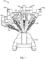
- FIG. 1 is a front view of the patient side cart component 100 of a teleoperated surgical system.
- a teleoperated surgical system allows a surgeon, with the assistance of a surgical team, to perform diagnostic and corrective surgical procedures on a patient.
- Such a teleoperated surgical system is described in U.S. Patent No. 8,545,515, published October 1, 2013 .
- the patient side cart includes a base 102 that rests on the floor, a support tower 104 that is mounted on the base 102, and several arms that support surgical tools (which include a stereoscopic endoscope).
- surgical tools may be arranged according to the embodiments described in U.S. Patent No. 6,817,974, published November 16, 2004 , and U.S. Patent No. 6,394,998, published May 28,2002 .
- arms 106a, 106b are instrument arms that support and move the surgical instruments used to manipulate tissue
- arm 108 is a camera arm that supports and moves the endoscope.
- FIG. 1 also shows an optional third instrument arm 106c that is supported on the back side of support tower 104 and that can be positioned to either the left or right side of the patient side cart as necessary to conduct a surgical procedure.
- FIG. 1 further shows interchangeable surgical instruments 110a, 110b, 110c mounted on the instrument arms 106a, 106b, 106c, and it shows an endoscope 112 mounted on the camera arm 108.
- a surgical instrument 110a may be mounted to an arm 106a via a manipulator portion 120 (patient side manipulator "PSM”) that supports and moves the surgical instrument.
- PSM patient side manipulator
- FIG. 2 is a top view of an exemplary embodiment of a surgical instrument 200.
- Surgical instrument 200 may include a force transmission mechanism 210, an end effector 220 at a distal end 224 of the surgical instrument, and a shaft 222 connecting force transmission mechanism 210 and end effector 220.
- Surgical instrument 200 may include one or more members to translate force between force transmission mechanism 210 and end effector 220.
- one or more member(s) 226 may connect force transmission mechanism 210 to end effector 220 to provide actuation forces to end effector 220, such as by extending through an interior of shaft 222.
- force transmission mechanism 210 may actuate end effector 220 to, for example, control a wrist mechanism of instrument 200 and/or to control a jaw of end effector 220 (or other moveable part). Further, because end effector 220 may be fixed to shaft 222, force translated from force translation mechanism 210 to end effector 220 may in turn be translated to shaft 222, such as when force translation mechanism 210 actuates end effector 220 in a rolling motion.
- Member(s) 226 may be in the form of tension elements, such as when force transmission mechanism 210 is a pull-pull mechanism, or one or more force isolation rods, such as when force transmission mechanism 210 is a push-pull mechanism, such as a drive rod element, as described in U.S. Patent No. 8,545,515, published October 1, 2013 .
- Force transmission mechanism 210 may include one or more components to engage with a patient side cart 100 to translate a force provided by patient side cart to surgical instrument 200.
- force transmission mechanism 210 may include one or more interface disks 212, 214 that engage with a PSM 120 of a patient side cart 100.
- interface disks 212, 214 may couple with actuators (e.g., servomechanisms) (not shown) in PSM 120 and translate a force from the actuators (e.g., servomechanisms) to surgical instrument 200.
- actuators e.g., servomechanisms
- interface disks 212, 214 utilize the actuation forces from PSM 120 to actuate instrument 200.
- first disk 212 may be configured to provide a rolling motion to shaft 222 and provide a roll DOF for end effector 220, while second disk 214 may operate a jaw mechanism of end effector 220 to open and close.
- the force transmission mechanism of FIG. 2 provides an accurate translation of rotational and translation movement of a control element to a surgical instrument of a teleoperated surgical system.
- force transmission mechanisms require many moving parts and intermeshed elements, increasing manufacturing costs and making maintenance and cleaning more difficult, potentially limiting the number of times such an element may be used.
- Force transmission mechanism 500 may include features of the force transmission embodiments discussed above, including the features of the force transmission mechanism of the embodiments described in U.S. Patent No. 8,545,515, published October 1, 2013 .
- force transmission mechanism 500 may include an input or interface disk 506 that may interface with another device to provide force or motion to an instrument, such as by coupling with an actuator (e.g., servomechanism) of a PSM, such as, for example, a carriage of a PSM.
- actuator e.g., servomechanism
- input disk 506 may provide a translational movement for the end effector, such as to open and close a jaw mechanism of the end effector, and a second input or interface disk (not shown) may provide a rotational movement to a shaft (not shown), as will be discussed below.
- Force transmission mechanism 500 may include a base 504 to which components of the force transmission mechanism 500 may be mounted or attached. As shown in the exemplary embodiment of FIG. 3 , a force transmission mechanism 500 may include an input disk 506. Input disk 506 may couple with an actuator (e.g., a servomechanism), such as, for example, a force transmission disk of a carriage of PSM 120 to couple actuation forces from actuators (e.g., servomechanisms) in PSM 120.
- an actuator e.g., a servomechanism
- Force transmission mechanism 500 may further include a gear 508, as shown in the exemplary embodiment of FIG. 3 .
- the gear 508 may be a gear having a geometry or configuration useful for saving space within the force transmission mechanism 500.
- gear 508 may be a sector gear 508.
- gear 508 will be referred to as a sector gear 508, although other gear configurations may be used.
- a sector gear 508 may require less space and require fewer parts than other gear configurations. For instance, only a portion 507 of sector gear 508 may include teeth or other structure that engage with corresponding teeth or other structure of the input disk 506, as shown in the exemplary embodiment of FIG. 6 , instead of an entire outer perimeter or circumference of the gear including teeth or other structure to engage with the input disk 506. Further, as will be discussed below, because sector gear 508 may include teeth or other engaging structure on only a portion 507 of the gear 508, the gear 508 may move through a limited amount of space within the force transmission mechanism 500 when the input disk 506 provides a torque to the sector gear 508. As a result, relatively little open space is required within the force transmission mechanism 500 to accommodate the rotational movement of the sector gear 508.
- Sector gear 508 may be coupled or otherwise connected to a push/pull drive element rod 502, as shown in the exemplary embodiment of FIG. 3 .
- Push/pull drive element rod 502 may be coupled to an end effector of a surgical instrument (not shown) so that pushing and pulling rod 502 may actuate the end effector.
- pushing on push/pull drive element rod 502 may open the jaws of the forceps, while pulling on rod 502 may close the jaws.
- pushing and pulling on the rod 502 would open and close the shears.
- an end effector coupled to push/pull drive element rod 502 may be arranged according to the exemplary embodiments described in U.S. Patent No. 8,545,515, published October 1, 2013 .
- sector gear 508 may be coupled to the input disk 506.
- an actuator e.g., servomechanism
- the sector gear 508 may convert its rotational movement to a substantially linear movement of the rod 502.
- the connection between the sector gear 508 and the rod 502 may permit rotational movement of the rod 502 in addition to a linear, translational movement of the rod 502.
- an exploded perspective view of the force transmission mechanism 500 is shown to further illustrate features of the exemplary embodiment of the force transmission mechanism 500 shown in FIG. 3 .
- an input disk 506 may be inserted through an aperture 537 in the base 504 of the force transmission mechanism 500 so that the input disk 506 may engage with a sector gear 508.
- input disk 506 may include teeth 505 or other structure to engage with the portion 507 of sector gear 508 that includes teeth or other corresponding structure to engage the input disk 506 and the sector gear 508.
- Components of the force transmission mechanism 500 may be configured to use a gear ratio from amongst a range of gear ratios. For instance, various gear ratios would be acceptable depending on a required torque and length of travel required for a specific instrument and/or end effector. Higher gear ratios may result in a larger amount of available torque and relatively lower amount of travel of a push/pull drive element rod, which may be advantageous for grasping. For instance, relatively large amounts of torque may be useful for grasping a suture needle or firing a clip. Lower gear ratios may result in lower available torque but a relatively large amount of travel for a push/pull drive element rod.
- a force transmission mechanism may employ gear ratios in a range of about 2:1 to about 8:1, depending upon a specific application of the force transmission mechanism.
- a force transmission mechanism may employ gear ratios in a range of about 3:1 to about 3.5:1. These gear ratios may be utilized by components of a force transmission mechanism and different components may use different gear ratios.
- the engaging structures of input disk 506 and sector gear 508 may be structured to provide a gear ratio of, for example, approximately 5:1, such as approximately 60:12.
- input disk 506 may be attached or otherwise mounted to a first side 501 or reverse side of the force transmission mechanism 500, while sector gear 508 is attached or otherwise mounted to a second side 503 or interior side of the force transmission mechanism 500. Portions of the sector gear 508 and the input disk 506 may engage one another via the aperture 537 in the base 504 of the force transmission mechanism 500.
- a force transmission mechanism 500 may include one or more structures to support the sector gear 508.
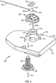
- a force transmission mechanism 500 may include a bearing 514 located under a sector gear 508, as shown in FIG. 4 .
- Bearing 514 may be inserted into a pocket 535 of the base 504, which may include a structure (not shown) to support the bearing 514 within aperture 535.
- the base 504 of the force transmission mechanism 500 may form a flange or ledge (not shown) within pocket 535 that the bearing 514 rests upon.
- sector gear 508 may be connected to a push/pull drive element rod 502 so that when a torque is applied to sector gear 508 via input disk 506, the rotational movement of the sector gear 508 may be converted to a substantially linear movement of the rod 502, which may in turn actuate an end effector of a surgical instrument to which rod 502 is coupled.
- push/pull drive element rod 502 may be connected to sector gear 508 via a ball connection 520, as shown in FIG. 4 .
- Ball connection 520 may have a shape of, for example, a substantially spherical ball with a hole 524 through the ball connection 520 that rod 502 may pass through, as indicated in FIG. 4 .
- Hole 524 may, for example, substantially pass through a center of the ball connection 520 and be substantially the size of an outer diameter of the rod 502.
- a size for the substantially spherical ball may be selected, for example, in order to balance available space within a force transmission mechanism, required force to be generated, and costs of the part(s).
- the ball may be relatively small to save cost and space within a force transmission mechanism.
- the ball should not be too small so that it is difficult to retain the ball within a force transmission mechanism.
- the ball may simply require additional cost and space without additional benefit.
- the ball may have a diameter of about 0.125 inches (about 3.175 mm) to about 0.5 inches (about 12.7 mm).
- the ball may have a diameter of about 0.25 inches (about 6.35 mm).
- ball connection 520 may include one or more structures to affix the ball connection 520 to the push/pull drive element rod 502. Such structures may fix the position of the ball connection 520 relative to the length of the rod 502 so that when sector gear 508 provides a translational motion to rod 502 via ball connection 520, the rod 502 simply does not slide within the ball connection 520 but is pushed and pulled as a result of the ball connection 520.
- ball connection 520 may include one or more fasteners 522 that connect the ball connection 520 to the rod 502.
- a fastener 522 may be formed as a separate piece that is connected to or engaged with a ball element or portion 526 of the ball connection 520, via, for example, a weld, mechanical connection, or other joint used in the art, or fastener 522 and ball element 526 may be formed via a monolithic, single-piece construction.
- the hole 524 of a ball connection 520 may pass through and be formed by both a ball element 526 and one or more fasteners 522 of the ball connection 520.
- fastener 522 may, for example, be substantially in the form of a cylinder that rod 502 passes through, as shown in FIG. 5A .
- rod 502 may be fixed to ball connection 520 via the one or more fasteners 522.
- rod 502 may be fixed to fastener 522 by applying a force to fastener 522 to cause fastener 522 to deform and crimp about the rod 502 so that fastener 522 no longer moves relative to rod 502.
- fastener 522 may be referred to as a "crimp" due to the deformation of the fastener 522 upon the rod 502 to fix the fastener 522 to the rod 502.
- the method of joining the rod 502 to one or more fasteners 522 of a ball connection 520 is not limited to this embodiment and other methods may be used, such as, for example, via a weld, a threaded connection, adhesive, and other joining methods used in the art. Because the ball connection 520 (including the ball element 526 which is joined to fastener 522 or formed as a single, monolithic piece with fastener 522) is fixed to rod 502, whenever the sector gear 508 moves the ball connection 520 the ball connection 520 may in turn move rod 502.
- a ball connection 520 may include a plurality of fasteners 522.
- a ball connection 520 may include a fastener 522 on each side of the ball element 526 of the ball connection 520 so that the ball connection 520 includes first and second fasteners 522 on opposite side of the ball element 526.
- Each fastener 522 may be fixed to rod 502 according to any of the methods described above, such as by crimping each fastener 522.
- the plurality of fasteners 522 may be formed as a monolithic, single piece construction with the ball element 526 of a ball connection 520 or may be separate pieces joined to the ball element 526, as described above.
- fasteners 522 may be provided as separate pieces from ball element 526, with each fastener 522 fixed to the rod 502 so that the ball element 526 is substantially held in place between the fasteners 522.
- a force transmission mechanism 500 may be connected to a surgical instrument and the rod 502 of the force transmission mechanism 500 may be used to actuate an end effector of the surgical instrument. If a precise connection is not made between a rod 502 and a sector gear 508, the end effector may not be actuated according to the desires of a user.
- the forceps might not open or close fully because an imprecise connection between a rod 502 and a sector gear 508 does not provide a full range of motion for the forceps, such as when there is too much slack in the connection.
- tolerances for a connection between a push/pull drive element rod 502 and a sector gear 508 of a force transmission mechanism 500 may be controlled or otherwise affected by controlling the location of where a ball connection 520 is fixed to the rod 502. For instance, during assembly of a force transmission mechanism 500, a push/pull drive element rod 502 may be inserted through a hole 524 of a ball connection 520 until the ball connection 520 is located at a point along an axial length of the rod 502 that will provide a precise connection to the rod 502.
- the ball connection 520 may be fixed to the rod 502 at that location, such as via one or more fasteners 522, as discussed above. As a result, tolerances may be kept relatively small in the connection and the rod 502 may be used to actuate the end effector of a surgical instrument with relatively accurate movements.
- the ball connection 520 may further be connected to a sector gear 508, as will be explained below, to complete a connection between the rod 502 and the sector gear 508.
- force transmission mechanism 500 may include one or more features to assist with assembly of the force transmission mechanism 500.
- a base 504 of the force transmission mechanism 500 may include an alignment aperture 518.
- a key (not shown), such as a pin or other elongated structure, may be inserted through alignment aperture 518 and through an indentation 519 in the sector gear 508.
- the sector gear 508 may be temporarily prevented from rotating relative to the base 504. This may advantageously facilitate securing a ball connection 520 to the sector gear 508 by preventing the sector gear 508 from turning during the assembly process.
- the key may be withdrawn from the indentation 519 and alignment aperture 518 to permit rotation of the sector gear 508.
- a sector gear 508 may include one or more structures to connect a ball connection 520 to the sector gear 508.
- a sector gear 508 may include a socket 527 that the ball connection 520 is inserted into. Once placed within the socket 527, a ball connection 520 may be fixed to a sector gear 508 so that rotational movement of the sector gear may be converted by the ball connection 520 to a substantially linear movement of a rod 502 fixed to the ball connection, while permitting free rotation of the ball connection 520 within the socket 527.
- an opening for socket 527 may be slightly smaller than a ball connection 520 so that the ball connection 520 may be secured within the socket 527 of the sector gear 508 by pressing the ball connection 520 through the opening of the socket 527 in a snap-fit type of arrangement.
- an opening of the socket 527 may be slightly smaller than a diameter of the ball element 526 of a ball connection 520.
- a socket 527 within a sector gear 508 for a ball connection 520 may be formed by one or more projections of the sector gear 508.
- a sector gear 508 may include projections 513, 515 that form a socket 527 between the projections 513, 515.
- projections 513, 515 may be formed with undercuts 529 to assist with securing a ball connection 520 within the socket 527, as shown in FIG. 5B .
- the undercuts 529 may form an opening 528 for the socket 527 that is slightly smaller than the ball connection 520, as shown in FIG.
- projections 513, 515 may be provided as discrete projections separate from one another and may be placed on opposite sides of a ball connection 520.
- a single, continuous projection (not shown) may be provided that forms an opening for a socket 527 and secures the ball connection 520 in place.
- a ball connection 520 may be secured to a sector gear 508 by placing the ball connection within a recess of the sector gear 508 and then covering at least a portion of the ball connection 520.
- sector gear 508 may include a recess 511 that a ball connection 520 is inserted into and a plate 512 may be placed over at least a portion of the ball connection 520 to secure the ball connection 520 to the sector gear 508.
- the recess 511 may, for example, have a shape of a pit having an opening substantially the size of the ball connection 520, such as the ball element 526, with a bottom of the recess conforming in shape to the outer surface of the ball element 526.
- the plate 512 may be secured to the sector gear 508 by, for example, one or more mechanical fasteners, welds, adhesive, or other connections used in the art.
- Connecting a ball connection 520 to a sector gear 508 via a plate 512 may be advantageous when greater forces are exerted between the sector gear 508, ball connection 520, and rod 502 because the plate may be able to withstand a greater pull-out force for the ball connection 520 than other connections, such as when only a socket 527 is provided with undercuts 529.
- a ball connection 520 may be secured to a sector gear 508 using only a socket 527 according to the embodiments described above without further structures or assistance to connect the ball connection 520 to the sector gear 508.
- a ball connection 520 may be secured to a sector gear 508 such both a socket 527 and a plate 512, with each of the socket 527 and plate 512 arranged according to the exemplary embodiments described above.
- a sector gear 508 may be secured to a base 504 of a force transmission mechanism 500 before or after a ball connection 520 is secured to the sector gear 508.
- a sector gear 508 may be held to the base 504 by one or more tabs or flanges 516.
- Tabs 516 may be part of the base 504 and may be formed as a monolithic, single piece construction with base 504 or may be separate pieces joined to base 504.
- Tabs 516 may permit rotational movement of sector gear 508 relative to base 504, such as when input disk 506 imparts a rotational movement to sector gear 508.
- tabs 516 may include detent structures to engage with the sector gear 508 so that rotational movement of the sector gear 508 may be limited.
- a force transmission mechanism 500 with a ball connection 520, a compact connection may be advantageously provided between a push/pull drive element rod 502 and a sector gear 508 with fewer parts so that the push/pull drive element 502 and the sector gear 508 are operatively coupled. Further, because fewer parts are utilized, less space is used within the force transmission mechanism 500 for the parts connecting the sector gear 508 to a rod 502. For example, as described in U.S. Application No. 12/618,583, filed on November 13, 2009 , published as U.S. Pub. No. 2011/0071542 on March 24, 2011 a force transmission mechanism may include a gear connected to a drive element rod via a link, slider, and a rolling bearing.
- a force transmission mechanism 500 may be directly connected to a push/pull drive element rod 502 with a ball connection 520.
- a ball connection 520 may be directly connected to a sector gear 508.
- a ball connection 520 may be in direct contact with the sector gear 508, such as a socket 527 and/or a plate 512 of the sector gear 508.
- a push/pull drive element rod 502 may be directly connected to a ball connection 520.
- the rod 502 may be in direct contact with the ball connection 520, including one or more fasteners 522 of the ball connection 520.
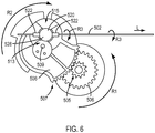
- FIG. 6 an exemplary embodiment of a connection is shown between a push/pull drive element rod 502, ball connection 520, and a sector gear 508.
- the remaining features of a force transmission mechanism 500 have been omitted in FIG. 6 for ease of viewing. As shown in FIG.
- an input disk 506 may be engaged with the sector gear 508, such as via teeth 505 or other structure of input disk 506 that engage with the portion 507 of sector gear 508 that includes teeth or other corresponding structure, so that when a rotational movement is imparted to the input disk 506 in direction R1, around rotation axis 531 (shown in the exemplary embodiment of FIG. 4 ), the sector gear 508 may be rotated in direction R2 (around rotation axis 509 shown in the exemplary embodiment of FIG. 4 ).
- rotation axis 531 of input disk 506 and rotation axis 509 of sector gear 508 may be substantially parallel to one another.
- a push/pull drive element rod 502 is connected to the sector gear 508 via ball connection 520, when sector gear 508 rotates in direction R2, ball connection 520 is carried along by sector gear 508, causing rod 502 to be translated in a substantially linear direction L, as shown in FIG. 6 .
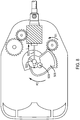
- FIG. 7 may show a first state of a force transmission mechanism 500
- FIG. 8 may show a second state of a force transmission mechanism 500.
- the first state shown in FIG. 7 may be a state in which the forceps are closed
- the second state shown in FIG. 8 may be a state in which the forceps are open. Therefore, as shown in FIG.
- sector gear 508 may rotate in direction R2 to cause rod 502 to advance forward in a substantially linear direction L, as shown in FIG. 8 , and actuate the surgical instrument.
- rod 502 may be translated forward to move actuate an end effector of an instrument from a closed position to an open position.
- ball connection 520 is fixed to rod 502 and ball connection 520 is free to rotate relative to the sector gear 508, when the rod 502 is rotated in direction R3, such as when a surgical instrument (not shown) that rod 502 is connected to rotates, ball connection 520 may also rotate in direction R3 about an axis of ball connection 520 relative to the sector gear 508, as shown in FIG. 6 .
- a force transmission mechanism 500 may include one or more structures to cause rotation of a surgical instrument.
- a force transmission mechanism 500 may include a second input disk 530.
- Second input disk 530 may be engaged with a gear 532, which in turn is engaged with a proximal end of a shaft 540 of a surgical instrument, as shown in FIG. 7 .
- the shaft 540 may include or otherwise be engaged to a shaft roll gear 542 that is engaged with gear 532.
- shaft 540 may include a flush fluid entry port 544 at the proximal end of the instrument shaft 540. In the depicted implementation of FIG.
- the flush fluid port 544 is made part of the assembly that couples the shaft 540 to the roll gear 542, or is otherwise a part of the portion of the shaft 540 that forms the roll gear 542.
- Flush fluid may be directed into the port 544 to clean components inside the shaft 540. For example, even though an actuating drive rod or cable may extend through a wipe seal at the distal end of the shaft 540, a small amount of body fluid may pass the seal and enter the inside of the shaft body.
- second input disk 530 may couple with a force transmission disk of a carriage, such as carriage 212 of a PSM 204 to couple actuation forces from actuators 232 in PSM 204 shown in the exemplary embodiment of FIG. 2B.
- second input disk 530 may be rotated in direction R4, as shown in FIG. 7 .
- gear 532 may be rotated in direction R5, causing roll gear 542 and shaft 540 to rotate in direction R6 about a longitudinal axis of shaft 540, as shown in FIG. 7 , due to the engagement between roll gear 542, gear 532, and second input disk 530.
- input disk 506 may actuate an end effector of a surgical instrument, such as to open and close a jaw mechanism of an end effector, while second input disk 530 may roll a shaft 540 of the surgical instrument so as to provide a roll DOF for the end effector of the surgical instrument.
- an end effector of a surgical instrument is coupled to shaft 540, the end effector is rotated when the shaft 540 is rotated.
- rod 502 is coupled to the end effector to actuate it, rod 502 is rotated in direction R3 when the shaft 540 is rotated in direction R6, as shown in FIG. 7 .
- the ball connection 520 that couples the rod 502 to the sector gear 508 permits rotational movement of the rod 502 relative to the sector gear 508, while also converting rotational movement of the sector gear 508 into a substantially linear movement.
- the rotational movement of a sector gear 508 may be converted into a substantially linear movement of a push/pull drive element rod 502 via a ball connection 520.
- a ball connection 520 When examined closely, one may determine that the motion of the ball connection 520 and portions of the rod 502 connected to the ball connection 520 and proximate to the ball connection 520 may travel through an arc as the sector gear 508 is rotated.
- FIG. 9A a top view of a sector gear 508, ball connection 520, and push/pull drive element rod 502 is shown in a first, initial state when rod 502 is in a withdrawn position.
- sector gear 508 rotates in direction R2 around its axis 509, ball connection 520 is carried by sector gear 508 to push rod 502 in a substantially linear direction L, as shown in FIG 9B .
- the rotation of sector gear 508 may continue to advance ball connection 520 and rod 502 to a forward position, as shown in FIG. 9C .
- FIG. 10A the positions of the ball connection 520 and rod 502 are shown relative to the sector gear axis 509 for the arrangement shown in FIG. 9A .
- FIG. 10B depicts the positions of the ball connection 520 and rod 502 relative to the sector gear axis 509 for the arrangement of FIG. 9B
- FIG. 10C depicts the positions of the ball connection 520 and rod 502 relative to the sector gear axis 509 for the arrangement of FIG. 9C .
- FIGS. 10A-10C as sector gear 508 rotates about axis 509, ball connection 520 is carried by the sector gear 508 and revolves around axis 509.
- ball connection 520 may travel along an arc 550 about axis 509 as the sector gear 508 rotates. This may cause a vertical distance between the ball connection 520 and the axis 509, such as from a center of ball connection 520 to axis 509, to vary, with a first distance X1 between ball connection 520 and axis 509 in FIG. 10A being less than a second distance X2 in FIG. 10B . Further, a third distance X3 shown in FIG. 10C may be less than the second distance X2 in FIG. 10B . Third distance X3 may be, for example, the same as first distance X1 or may be substantially the same. Further, a portion of the rod 502 connected to the ball connection 520, and possibly portions of the rod 502 proximate to the ball connection 520, may also travel in an arc 550 relative to axis 509.
- the motion induced in the rod 502 may be considered to be a substantially linear direction.
- a motion induced in rod 502 proximate to the end effector of a surgical instrument may be in a substantially linear direction.
- a force transmission mechanism may include a structure to support a push/pull drive element rod.
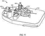
- FIG. 11 an exemplary embodiment of a force transmission mechanism 600 that includes a guide 620 configured to support a push/pull drive element rod 602.
- Guide 620 may be connected to a base 604 and may include an aperture through which rod 602 passes, as shown in the exemplary embodiment of FIG. 11 .
- guide 620 may advantageously reduce an unsupported length of rod 602 and may minimize or eliminate deflection or buckling of rod 602.
- guide 620 may cut the unsupported length of rod 602 in half. As shown in the exemplary embodiment of FIG.
- guide 620 may have a conical or substantially frusto-conical shape. Although the unsupported length of rod 602 may be reduced in comparison to rod 502 of the embodiment of FIGS. 9A-9C , rod 602 may experience a similar or same movement as rod 502, as illustrated in FIGS. 10A-10C .
- the force transmission mechanism 600 may include a pocket 605 and an aperture 607 in base 604, an input disk 606, a bearing 614, a sector gear 608, a ball connection 610 with one or more fasteners 611. These features may be arranged according to the embodiments described above, such as the embodiment of FIG. 3 . According to an exemplary embodiment, the force transmission mechanism 600 may further include a plate 612, as described above for the embodiment of FIG. 4 .
- a force transmission mechanism may include one or more devices to bias push/pull drive element rod to an initial position when a torque is not applied to a sector gear.
- FIG. 13 an exemplary embodiment of a force transmission mechanism 700 is shown that includes a sector gear 708 and ball connection 720 connected to a push/pull drive element rod 702. These features may be arranged according to the embodiments described above, such as the embodiment of FIG. 3 .
- the force transmission mechanism 700 may further include a plate 712, as described above for the embodiment of FIG. 4 .
- Force transmission mechanism 700 may further include a biasing device 730 to exert a force to bias sector gear 708, such as in direction D shown in the exemplary embodiment of FIG. 13 .
- biasing device 730 may function to pull rod 702 in direction D so that the forceps or shears are actuated to a closed configuration (e.g., a biased position).
- a closed configuration e.g., a biased position
- the biasing device 730 may advantageously prevent or minimize a back side of the end effector from striking a cannula (not shown) during withdrawal or removal of a surgical instrument through the cannula.
- the backs of an end effector such as the jaws of forceps, could have an insulative coating that could be damaged if the jaws strike the cannula during withdrawal of the forceps.
- biasing device 730 may be a spring.
- the spring force may be selected based on the intended application of the end effectors, and may, for example, to chosen to minimize friction or to maximize grip force.
- the spring may exert a force in a range of, for example, approximately half a pound to approximately 3 pounds.
- a spring may exert a force in a range of, for example, approximately half a pound to approximately 8 pounds.
- a biasing force of a spring may be in a range of, for example, approximately half a pound to approximately 6 pounds.
- a biasing force of a spring may be in a range of, for example, approximately half a pound to approximately 3 pounds.
- a biasing force of a spring may be in a range of, for example, approximately half a pound to approximately 2 pounds.
- a spring may be selected to exert no less than approximately a half pound of force upon rod 702 because less force may not be sufficient to overcome friction and pull rod 702 in direction D shown in FIG. 13 .
- a spring may be selected to exert no more than 2 pounds or 3 pounds so that a dissecting force of an end effector of a surgical instrument is not substantially reduced or negatively impacted.
- a dissecting force is a force used when the end effector placed against tissue or within a tissue gap to push tissue apart. If a biasing force is too great, the spring may prevent a rod 702 from being advanced with sufficient force to allow an end effector to provide a dissecting force.
- an instrument may be used for applications other than dissection.
- biasing force of a spring could be used to obtain a greater amount of grip. This may be limited by the ability of an input disk to overcome the biasing force of the spring in order to open up the end effectors of an instrument.
- biasing device 730 may be a spring, the biasing device is not limited to a spring and may be other types of biasing devices.
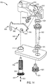
- Force transmission mechanism 800 may include a chassis 810 and a base 812 to support features of force transmission mechanism 800.
- Force transmission mechanism 800 may further include a shaft roll input gear 820 that engages with a shaft roll output gear 822 to provide a rolling motion to a shaft of an instrument (not shown).
- a bottom portion 821 of shaft roll input gear 820 may couple with a carriage of a PSM to receive a rotational force, causing shaft roll input gear 820 to rotate, which in turn causes shaft roll output gear 822 to rotate an instrument shaft.
- Shaft roll input gear 820 and shaft roll output gear 822 may be supported by one or more bearings 824, as shown in the exemplary embodiment of FIG. 14 .
- Force transmission mechanism 800 may further include a rocker input gear 830 and a rocker member 840.
- Rocker member 840 may be connected to chassis 810.
- chassis 810 may include a projection 814 that fits through an aperture 848 of rocker member 840 so that rocker member 840 may pivot about projection 814.
- At least one bearing 844 may be provided to support rocker member 840 on projection 814, according to an exemplary embodiment. As shown in the exemplary embodiment of FIG. 14 , at least two bearings 844 may be provided to distribute a load between rocker member 840 and projection 814.
- rocker member 840 may be connected to an end effector of an instrument (not shown).
- rocker member 840 may include a ball connection 842.
- Ball connection 842 may be configured according to the exemplary embodiments of FIGS. 3-13 discussed above.
- a push/pull drive element rod 860 coupled to an end effector of a surgical instrument may be connected to ball connection 842.
- Ball connection 842 may permit both rotational and translational movement of push/pull drive element rod 860, such as, for example, in translation along direction 872 and rotation in direction 874 shown in the exemplary embodiment of FIG. 15 .
- ball connection 842 may be received within a recess or socket 816 of rocker member 840 to connect rocker member 840 and ball connection 842 to one another.
- Socket 816 may be configured according to the exemplary embodiments of FIGS. 3-13 discussed above.
- rocker member 840 may include one or more wall portions 818 to facilitate fastening ball connection 842 within socket 816.
- wall portions 818 may be projections (not shown) that extend into socket 816 to facilitate fastening ball connection 842 within socket 816.
- ball connection 842 may snap fit into socket 816.
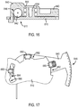
- a portion 811 of chassis 810 may cover at least a portion of socket 816 and ball connection 842, as shown in FIG. 16 , to assist in holding ball connection 842 within socket 816.
- Rocker member 840 may be connected to chassis 810, for example, via one or more hooks 880, on one of rocker member 840 and chassis 810, with the hooks 880 engaging with guide surfaces 882, 884, as shown in the exemplary embodiment of FIG. 17 .
- Guide surfaces 882 may be convex and guide surface 884 may be concave, as shown in FIG. 17 .
- Rocker member 840 and chassis 810 may be assembled together, for example, by engaging one or more hooks 880 with guide surface(s) 882 and by inserting a hook 880 through a slot 886 in chassis 810, according to an exemplary embodiment. Subsequently, rocker member 840 may be rotated in a counter-clockwise direction in FIG. 17 to engage hook 880 with guide surface 884. During operation of a surgical instrument, hooks 880 remain engaged with guide surfaces 882, 884.
- rocker input gear 830 may input a force to rocker member 840 to actuate an end effector of an instrument.
- a bottom portion 831 of rocker input gear 830 may couple with a carriage of a PSM to receive a rotational force to rotate rocker input gear 830, such as around axis 833, which may in turn be input to rocker member 840.
- rocker input gear 830 may engage with rocker member 840 via gearing.
- rocker input gear 830 may include a section of helical gear teeth 832 that engage with a sector gear portion 846 of rocker member 840, as shown in FIGS. 14 and 15 .
- rocker input gear 830 when rocker input gear 830 is rotated in direction 834, such as around axis 845, as shown in the exemplary embodiment of FIG. 15 , helical gear teeth 832 urge sector gear portion 846 in direction 870, which in turn causes the remainder of rocker member 840 to pivot around projection 814 (not shown in FIG. 15 ) within aperture 848 in direction 870.
- ball connection 842 is connected to rocker member 840 within socket 816, ball connection 842 is moved along with rocker member 840, causing push/pull drive element rod 860 to be pulled substantially along direction 872 to actuate an end effector of a surgical instrument.
- rotation axis 845 of rocker member 840 and rotation axis 833 of rocker input gear 830 may be substantially perpendicular to one another.
- gears including sector gears and rocker members, may be made, for example, from autoclavable polyetherimide (PEI), such as Ultem®, so that the gears may be cleaned and sterilized and may be manufactured inexpensively.
- Such gears may further include glass fibers to add strength and rigidity.
- PEI may include glass fibers in a range of, for example, approximately 5% to approximately 15%. In another example, PEI may include glass fibers in a range of approximately 10%.
- the gears may include polytetrafluoroethylene (PTFE), such as Teflon®, to reduce friction between the gear and other parts, such as friction between a sector gear and a ball connection.
- PTFE polytetrafluoroethylene
- PEI may include PTFE in a range of, for example, approximately 10% to approximately 20%.
- PEI may include PTFE in a range of approximately 15%.
- a ball connection may be made of a metal or metal alloy.
- a ball connection may be made of stainless steel. Because a ball connection may be made of metal, the ball connection may serve as an electrical contact, such as when an electrical signal or current may be sent along a push/pull drive element rod.
- a push/pull drive element rod may be a metal or metal alloy, such as stainless steel, although other materials may be used, such as composites, fiberglass, electrically insulative materials, and carbon.
- an input disk may be made of aluminum or an aluminum alloy overmolded with plastic.
- the number of parts may be minimized and the cost of manufacturing the force transmission mechanism may be advantageously reduced while permitting the connection between the gear and the rod to provide both rotational movement and translational movement of the rod.
- the gear may be structured to move through a limited amount of space within the force transmission mechanism. As a result, relatively little open space is required within the force transmission mechanism to accommodate the rotational movement of the gear.
- spatially relative terms such as “beneath”, “below”, “lower”, “above”, “upper”, “proximal”, “distal”, and the like-may be used to describe one element's or feature's relationship to another element or feature as illustrated in the figures.
- These spatially relative terms are intended to encompass different positions (i.e., locations) and orientations (i.e., rotational placements) of a device in use or operation in addition to the position and orientation shown in the figures.
- orientations i.e., rotational placements
- the exemplary term “below” can encompass both positions and orientations of above and below.
- a device may be otherwise oriented (rotated 90 degrees or at other orientations) and the spatially relative descriptors used herein interpreted accordingly.
Claims (13)
- Mécanisme de transmission de force (210, 500, 600, 700, 800) pour un instrument chirurgical télécommandé (110a, 110b, 110c, 200), comprenant :un engrenage (508, 608, 708, 846) configuré pour être entraîné par un mécanisme d'entrée d'entraînement (212, 214, 506, 606, 831) ;un élément d'entraînement de type pousser/tirer (226, 502, 602, 702, 860) configuré pour transmettre une force pour actionner un effecteur terminal (220) de l'instrument chirurgical (110a, 110b, 110c, 200) ; etun élément de rotule (520, 526, 610, 720, 842) couplant de manière fonctionnelle l'engrenage (508, 608, 708, 846) et l'élément d'entraînement de type pousser/tirer (226, 502, 602, 702, 860),dans lequel le mouvement entraîné de l'engrenage (508, 608, 708, 846) est transmis à l'élément d'entraînement de type pousser/tirer (226, 502, 602, 702, 860) pour actionner l'effecteur terminal (220).
- Mécanisme de transmission de force (210, 500, 600, 700, 800) selon la revendication 1, dans lequel l'élément d'entraînement de type pousser/tirer (226, 502, 602, 702, 860) est une tige d'élément d'entraînement de type pousser/tirer.
- Mécanisme de transmission de force (210, 500, 600, 700, 800) selon la revendication 1, dans lequel l'élément de rotule (520, 526, 610, 720, 842) couple de manière fonctionnelle l'engrenage (508, 608, 708, 846) et l'élément d'entraînement de type pousser/tirer (226, 502, 602, 702, 860) pour convertir un mouvement de rotation de l'engrenage (508, 608, 708, 846) en un mouvement substantiellement linéaire de l'élément d'entraînement de type pousser/tirer (226, 502, 602, 702, 860).
- Mécanisme de transmission de force (210, 500, 600, 700, 800) selon la revendication 3, dans lequel l'élément de rotule (520, 526, 610, 720, 842) peut tourner librement par rapport à l'engrenage (508, 608, 708, 846) autour d'un axe de l'élément de rotule (520, 526, 610, 720, 842) .
- Mécanisme de transmission de force (210, 500, 600, 700, 800) selon la revendication 1, dans lequel l'engrenage (508, 608, 708, 846) est un engrenage denté.
- Mécanisme de transmission de force (210, 500, 600, 700, 800) selon la revendication 5, dans lequel l'engrenage denté (508, 608, 708, 846) inclut une emboîture (527, 816) et dans lequel l'élément de rotule (520, 526, 610, 720, 842) est reçu dans l'emboîture (527, 816).
- Mécanisme de transmission de force (210, 500, 600, 700) selon la revendication 5, dans lequel le mécanisme d'entrée d'entraînement (212, 214, 506, 606) comprend un engrenage d'entrée en prise avec l'engrenage denté (508, 608, 708), dans lequel un axe de rotation (531) de l'engrenage d'entrée et un axe de rotation (509) de l'engrenage denté (508, 608, 708) sont substantiellement parallèles l'un à l'autre.
- Mécanisme de transmission de force (800) selon la revendication 5, dans lequel le mécanisme d'entrée d'entraînement (831) comprend un engrenage d'entrée en prise avec l'engrenage denté (846), dans lequel l'engrenage denté (846) fait partie d'un élément basculant (840), dans lequel un axe de rotation (833) de l'engrenage d'entrée et un axe de rotation (845) de l'élément basculant (840) sont substantiellement perpendiculaires l'un à l'autre.
- Mécanisme de transmission de force (210, 500, 600, 700, 800) selon la revendication 1, dans lequel l'élément d'entraînement de type pousser/tirer (226, 502, 602, 702, 860) passe au moins partiellement à travers l'élément de rotule (520, 526, 610, 720, 842).
- Mécanisme de transmission de force (210, 500, 600, 700, 800) selon la revendication 1, dans lequel le mécanisme d'entrée d'entraînement (212, 214, 506, 606, 831) comprend un disque d'entrée configuré pour entrer en prise avec un servomécanisme d'un système chirurgical télécommandé.
- Mécanisme de transmission de force (210, 500, 600, 700, 800) selon la revendication 10, comprenant en outre un deuxième disque d'entrée (530) configuré pour se coupler de manière fonctionnelle avec un arbre (222, 540) de l'instrument chirurgical (110a, 110b, 110c, 200) pour transmettre un mouvement de rotation à l'arbre (222, 540) autour d'un axe longitudinal de l'arbre (222, 540).
- Mécanisme de transmission de force (210, 500, 600, 700) selon la revendication 1, comprenant en outre une plaque (512, 612, 712), dans lequel l'élément de rotule (520, 526, 610, 720) est situé entre l'engrenage (508, 608, 708) et la plaque (512, 612, 712), ou
dans lequel l'engrenage (508, 608, 708) est connecté directement à l'élément de rotule (520, 526, 610, 720) et l'élément de rotule (520, 526, 610, 720) est connecté directement à l'élément d'entraînement de type pousser/tirer (226, 502, 602, 702), ou
dans lequel l'engrenage (508, 608, 708) entoure partiellement l'élément de rotule (520, 526, 610, 720). - Mécanisme de transmission de force (700) selon la revendication 1, comprenant en outre un dispositif de sollicitation (730) pour solliciter l'engrenage (708) et l'élément d'entraînement de type pousser/tirer (702) vers une position sollicitée, et préférablement
dans lequel le dispositif de sollicitation (730) est un ressort qui sollicite l'engrenage (508, 608, 708, 846) et l'élément d'entraînement de type pousser/tirer (226, 502, 602, 702, 860) vers la position sollicitée.
Applications Claiming Priority (2)
| Application Number | Priority Date | Filing Date | Title |
|---|---|---|---|
| US201361823688P | 2013-05-15 | 2013-05-15 | |
| PCT/US2014/037921 WO2014186412A2 (fr) | 2013-05-15 | 2014-05-13 | Mécanisme de transmission de force pour instrument chirurgical téléopéré |
Publications (3)
| Publication Number | Publication Date |
|---|---|
| EP2996620A2 EP2996620A2 (fr) | 2016-03-23 |
| EP2996620A4 EP2996620A4 (fr) | 2017-11-08 |
| EP2996620B1 true EP2996620B1 (fr) | 2020-09-16 |
Family
ID=51894709
Family Applications (1)
| Application Number | Title | Priority Date | Filing Date |
|---|---|---|---|
| EP14797262.4A Active EP2996620B1 (fr) | 2013-05-15 | 2014-05-13 | Mécanisme de transmission de force pour instrument chirurgical téléopéré |
Country Status (6)
| Country | Link |
|---|---|
| US (1) | US9664262B2 (fr) |
| EP (1) | EP2996620B1 (fr) |
| JP (2) | JP6416886B2 (fr) |
| KR (1) | KR102294062B1 (fr) |
| CN (2) | CN108095826B (fr) |
| WO (1) | WO2014186412A2 (fr) |
Families Citing this family (62)
| Publication number | Priority date | Publication date | Assignee | Title |
|---|---|---|---|---|
| US10076348B2 (en) | 2013-08-15 | 2018-09-18 | Intuitive Surgical Operations, Inc. | Rotary input for lever actuation |
| US10550918B2 (en) | 2013-08-15 | 2020-02-04 | Intuitive Surgical Operations, Inc. | Lever actuated gimbal plate |
| US10130437B2 (en) | 2013-08-15 | 2018-11-20 | Intuitive Surgical Operations, Inc. | Instrument shaft for computer-assisted surgical system |
| CN105813582B (zh) | 2013-12-11 | 2019-05-28 | 柯惠Lp公司 | 用于机器人手术系统的腕组件及钳夹组件 |
| USD768295S1 (en) * | 2014-03-17 | 2016-10-04 | Intuitive Surgical Operations, Inc. | Surgical instrument end portion |
| USD767129S1 (en) * | 2014-03-17 | 2016-09-20 | Intuitive Surgical Operations, Inc. | Surgical instrument end portion |
| USD767130S1 (en) * | 2014-03-17 | 2016-09-20 | Intuitive Surgical Operations, Inc. | Surgical instrument end portion |
| USD760387S1 (en) * | 2014-03-17 | 2016-06-28 | Intuitive Surgical Operations, Inc. | Surgical instrument end portion |
| CN110063791B (zh) | 2014-08-13 | 2022-04-15 | 柯惠Lp公司 | 机器人控制的具有机械优势的夹持 |
| EP3179953B1 (fr) * | 2014-08-15 | 2020-03-04 | Intuitive Surgical Operations, Inc. | Mécanisme de transmission de force pour instrument chirurgical |
| CN107249498B (zh) | 2015-02-19 | 2024-04-23 | 柯惠Lp公司 | 机器人手术系统的输入装置的重定位方法 |
| CN107405172B (zh) | 2015-03-10 | 2021-04-13 | 柯惠Lp公司 | 测量机器人手术系统的连接器部件的健康状况 |
| CN107666866A (zh) | 2015-06-03 | 2018-02-06 | 柯惠Lp公司 | 偏置器械驱动单元 |
| JP6761822B2 (ja) | 2015-06-16 | 2020-09-30 | コヴィディエン リミテッド パートナーシップ | ロボット外科用システムトルク変換検知 |
| JP6719487B2 (ja) | 2015-06-23 | 2020-07-08 | コヴィディエン リミテッド パートナーシップ | ロボット外科手術アセンブリ |
| WO2017053363A1 (fr) | 2015-09-25 | 2017-03-30 | Covidien Lp | Ensembles chirurgicaux robotisés et connecteurs d'entraînement d'instruments associés |
| WO2017070275A1 (fr) | 2015-10-23 | 2017-04-27 | Covidien Lp | Système chirurgical pour détecter des changements progressifs dans une perfusion |
| US10660714B2 (en) | 2015-11-19 | 2020-05-26 | Covidien Lp | Optical force sensor for robotic surgical system |
| US10398439B2 (en) * | 2016-02-10 | 2019-09-03 | Covidien Lp | Adapter, extension, and connector assemblies for surgical devices |
| WO2017156070A1 (fr) | 2016-03-09 | 2017-09-14 | Intuitive Surgical Operations, Inc. | Mécanisme de transmission de force pour instrument chirurgical, dispositifs, systèmes et procédés associés |
| WO2017173524A1 (fr) | 2016-04-07 | 2017-10-12 | Titan Medical Inc. | Procédé et appareil de positionnement de caméra pour capturer des images pendant une procédure médicale |
| JP6945560B2 (ja) | 2016-05-26 | 2021-10-06 | コヴィディエン リミテッド パートナーシップ | ロボット外科手術アセンブリ |
| CA3022139A1 (fr) | 2016-05-26 | 2017-11-30 | Covidien Lp | Unite de commande d'instruments |
| US11553984B2 (en) | 2016-06-03 | 2023-01-17 | Covidien Lp | Robotic surgical system with an embedded imager |
| CN114504387A (zh) | 2016-06-03 | 2022-05-17 | 柯惠Lp公司 | 用于机器人手术系统的被动轴系统 |
| WO2017210499A1 (fr) | 2016-06-03 | 2017-12-07 | Covidien Lp | Bras de commande pour systèmes chirurgicaux robotiques |
| EP3463162A4 (fr) | 2016-06-03 | 2020-06-24 | Covidien LP | Systèmes, procédés et produits de programme lisibles par ordinateur pour commander un manipulateur commandé par robot |
| USD864386S1 (en) | 2016-07-14 | 2019-10-22 | Intuitive Surgical Operations, Inc. | Surgical instrument actuator end portion |
| USD865164S1 (en) | 2016-07-14 | 2019-10-29 | Intuitive Surgical Operations, Inc. | Surgical instrument actuator end portion |
| US11007024B2 (en) | 2016-07-14 | 2021-05-18 | Intuitive Surgical Operations, Inc. | Geared grip actuation for medical instruments |
| WO2018013354A1 (fr) | 2016-07-14 | 2018-01-18 | Intuitive Surgical Operations, Inc. | Instruments chirurgicaux munis d'éléments d'actionnement électriquement isolés, dispositifs associés et procédés associés |
| WO2018013316A1 (fr) | 2016-07-14 | 2018-01-18 | Intuitive Surgical Operations, Inc. | Entraînement de rouleaux à engrenages pour instrument médical |
| USD865163S1 (en) | 2016-07-14 | 2019-10-29 | Intuitive Surgical Operations, Inc. | Surgical instrument actuator end portion |
| EP3582708A4 (fr) | 2017-02-15 | 2020-12-23 | Covidien LP | Système et appareil pour la prévention de l'écrasement pour des applications robotiques médicales |
| US11717361B2 (en) | 2017-05-24 | 2023-08-08 | Covidien Lp | Electrosurgical robotic system having tool presence detection |
| EP3629980A4 (fr) | 2017-05-25 | 2021-03-10 | Covidien LP | Système chirurgical robotique à guidage automatisé |
| CN110177518B (zh) | 2017-05-25 | 2023-01-31 | 柯惠Lp公司 | 用于在图像捕获装置的视场内检测物体的系统和方法 |
| EP3629983B1 (fr) | 2017-05-25 | 2023-06-28 | Covidien LP | Systèmes chirurgicaux robotiques et drapés pour recouvrir des composants de systèmes chirurgicaux robotiques |
| WO2019050829A1 (fr) | 2017-09-05 | 2019-03-14 | Covidien Lp | Algorithmes de gestion des collisions pour systèmes chirurgicaux robotiques |
| EP3678573A4 (fr) | 2017-09-06 | 2021-06-02 | Covidien LP | Mise à l'échelle des limites de robots chirurgicaux |
| CN111246817B (zh) * | 2017-11-02 | 2023-06-27 | 奥林巴斯株式会社 | 弯曲机构及医疗用机械手 |
| CA3091734C (fr) * | 2017-12-29 | 2023-01-03 | The Board Of Regents Of The University Of Texas System | Effecteur terminal et appareil d'entrainement d'effecteur terminal |
| AU2019205201B2 (en) | 2018-01-04 | 2020-11-05 | Covidien Lp | Systems and assemblies for mounting a surgical accessory to robotic surgical systems, and providing access therethrough |
| US11497567B2 (en) | 2018-02-08 | 2022-11-15 | Intuitive Surgical Operations, Inc. | Jointed control platform |
| US11118661B2 (en) * | 2018-02-12 | 2021-09-14 | Intuitive Surgical Operations, Inc. | Instrument transmission converting roll to linear actuation |
| US11189379B2 (en) | 2018-03-06 | 2021-11-30 | Digital Surgery Limited | Methods and systems for using multiple data structures to process surgical data |
| WO2019173056A1 (fr) | 2018-03-08 | 2019-09-12 | Covidien Lp | Systèmes robotiques chirurgicaux |
| USD884892S1 (en) | 2018-04-20 | 2020-05-19 | Intuitive Surgical Operations, Inc. | Surgical instrument backend housing |
| WO2019204012A1 (fr) | 2018-04-20 | 2019-10-24 | Covidien Lp | Compensation du mouvement d'un observateur dans des systèmes chirurgicaux robotisés ayant des affichages stéréoscopiques |
| CN108719406B (zh) * | 2018-05-11 | 2020-11-24 | 中画高新技术产业发展(重庆)有限公司 | 香猪屠宰设备 |
| EP3817683A4 (fr) | 2018-07-03 | 2022-04-20 | Covidien LP | Systèmes, procédés et supports lisibles par ordinateur pour détecter une dégradation d'image pendant des interventions chirurgicales |
| US11109746B2 (en) | 2018-10-10 | 2021-09-07 | Titan Medical Inc. | Instrument insertion system, method, and apparatus for performing medical procedures |
| US11586106B2 (en) | 2018-12-28 | 2023-02-21 | Titan Medical Inc. | Imaging apparatus having configurable stereoscopic perspective |
| US11717355B2 (en) | 2019-01-29 | 2023-08-08 | Covidien Lp | Drive mechanisms for surgical instruments such as for use in robotic surgical systems |
| US11576733B2 (en) | 2019-02-06 | 2023-02-14 | Covidien Lp | Robotic surgical assemblies including electrosurgical instruments having articulatable wrist assemblies |
| US11484372B2 (en) | 2019-02-15 | 2022-11-01 | Covidien Lp | Articulation mechanisms for surgical instruments such as for use in robotic surgical systems |
| CN113939117B (zh) * | 2020-06-29 | 2023-06-02 | 戴尔产品有限公司 | 用于模块化信息处理资源的齿轮系侧闩锁机构 |
| USD963851S1 (en) | 2020-07-10 | 2022-09-13 | Covidien Lp | Port apparatus |
| US11957422B2 (en) | 2020-10-15 | 2024-04-16 | Covidien Lp | Surgical instruments for use in robotic surgical systems and methods relating to the same |
| WO2022082350A1 (fr) * | 2020-10-19 | 2022-04-28 | 诺创智能医疗科技(杭州)有限公司 | Élément de transmission, ensemble d'entraînement, mécanisme d'exécution et robot chirurgical |
| US11948226B2 (en) | 2021-05-28 | 2024-04-02 | Covidien Lp | Systems and methods for clinical workspace simulation |
| CN113693731B (zh) * | 2021-09-03 | 2022-08-30 | 南京佗道医疗科技有限公司 | 一种可拆卸器械结构 |
Family Cites Families (18)
| Publication number | Priority date | Publication date | Assignee | Title |
|---|---|---|---|---|
| EP0647122B1 (fr) * | 1992-06-24 | 1998-02-04 | Microsurge, Inc. | Instrument chirurgical endoscopique reutilisable |
| US5395369A (en) * | 1993-06-10 | 1995-03-07 | Symbiosis Corporation | Endoscopic bipolar electrocautery instruments |
| JPH1071155A (ja) * | 1996-08-30 | 1998-03-17 | Olympus Optical Co Ltd | 内視鏡用処置具 |
| US7963913B2 (en) | 1996-12-12 | 2011-06-21 | Intuitive Surgical Operations, Inc. | Instrument interface of a robotic surgical system |
| US6394998B1 (en) | 1999-01-22 | 2002-05-28 | Intuitive Surgical, Inc. | Surgical tools for use in minimally invasive telesurgical applications |
| US6817998B2 (en) | 1999-07-23 | 2004-11-16 | Lahaye Leon C. | Method and apparatus for monitoring laser surgery |
| ATE547992T1 (de) * | 2001-06-29 | 2012-03-15 | Intuitive Surgical Operations | Gelenkmechanismus fuer plattformverbindung |
| US6817974B2 (en) | 2001-06-29 | 2004-11-16 | Intuitive Surgical, Inc. | Surgical tool having positively positionable tendon-actuated multi-disk wrist joint |
| US8820603B2 (en) * | 2006-01-31 | 2014-09-02 | Ethicon Endo-Surgery, Inc. | Accessing data stored in a memory of a surgical instrument |
| AU2008225255B2 (en) * | 2007-03-14 | 2012-05-31 | Tobeck, Colin Gilbert | A System for Manipulating a Fluid Cannon |
| US9386983B2 (en) | 2008-09-23 | 2016-07-12 | Ethicon Endo-Surgery, Llc | Robotically-controlled motorized surgical instrument |
| US8551115B2 (en) | 2009-09-23 | 2013-10-08 | Intuitive Surgical Operations, Inc. | Curved cannula instrument |
| CN101696719B (zh) * | 2009-10-29 | 2012-05-30 | 江苏唐邦机电有限公司 | 具有自定位锁紧功能的往复旋转机构 |
| CN102596063B (zh) * | 2009-11-13 | 2015-09-23 | 直观外科手术操作公司 | 弯曲套管手术系统 |
| CN101732093B (zh) * | 2009-11-30 | 2011-09-07 | 哈尔滨工业大学 | 腹腔微创手术用微型机械手 |
| WO2012166815A1 (fr) * | 2011-05-31 | 2012-12-06 | Intuitive Surgical Operations, Inc | Instrument chirurgical à commande pour état défectueux détecté |
| US20130035537A1 (en) * | 2011-08-05 | 2013-02-07 | Wallace Daniel T | Robotic systems and methods for treating tissue |
| DE102011088003A1 (de) * | 2011-12-08 | 2013-06-13 | Richard Wolf Gmbh | Medizinisches Instrument |
-
2014
- 2014-05-13 CN CN201810054561.8A patent/CN108095826B/zh active Active
- 2014-05-13 KR KR1020157032135A patent/KR102294062B1/ko active IP Right Grant
- 2014-05-13 US US14/277,000 patent/US9664262B2/en active Active
- 2014-05-13 JP JP2016514049A patent/JP6416886B2/ja active Active
- 2014-05-13 EP EP14797262.4A patent/EP2996620B1/fr active Active
- 2014-05-13 WO PCT/US2014/037921 patent/WO2014186412A2/fr active Application Filing
- 2014-05-13 CN CN201480025668.XA patent/CN105188593B/zh active Active
-
2018
- 2018-10-04 JP JP2018188845A patent/JP6668436B2/ja active Active
Non-Patent Citations (1)
| Title |
|---|
| None * |
Also Published As
| Publication number | Publication date |
|---|---|
| EP2996620A4 (fr) | 2017-11-08 |
| CN105188593B (zh) | 2018-02-23 |
| JP2019010561A (ja) | 2019-01-24 |
| JP6416886B2 (ja) | 2018-10-31 |
| US9664262B2 (en) | 2017-05-30 |
| CN108095826B (zh) | 2021-04-30 |
| CN105188593A (zh) | 2015-12-23 |
| CN108095826A (zh) | 2018-06-01 |
| WO2014186412A3 (fr) | 2015-04-02 |
| US20140338477A1 (en) | 2014-11-20 |
| EP2996620A2 (fr) | 2016-03-23 |
| JP2016524491A (ja) | 2016-08-18 |
| WO2014186412A2 (fr) | 2014-11-20 |
| JP6668436B2 (ja) | 2020-03-18 |
| KR20160008539A (ko) | 2016-01-22 |
| KR102294062B1 (ko) | 2021-08-26 |
Similar Documents
| Publication | Publication Date | Title |
|---|---|---|
| EP2996620B1 (fr) | Mécanisme de transmission de force pour instrument chirurgical téléopéré | |
| US20210338352A1 (en) | Force transmission mechanism for surgical instrument, and related systems and methods | |
| US11744662B2 (en) | Force transmission mechanism for surgical instrument, and related devices, systems, and methods | |
| US11666394B2 (en) | Surgical instruments, instrument drive units, and surgical assemblies thereof | |
| JP7019747B2 (ja) | 手術用器具の駆動要素及び関連する装置、システム、及び方法 | |
| US20190021801A1 (en) | Surgical instrument with commonly actuated robotic and manual features | |
| US20190298323A1 (en) | Geared grip actuation for medical instruments | |
| CN113729970B (zh) | 手术机器人、手术器械和力传递装置 | |
| US20220125528A1 (en) | Surgical instrument and operation robot | |
| WO2014134304A1 (fr) | Instrument chirurgical doté de mâchoires incurvées pour un système chirurgical | |
| US11850013B2 (en) | Surgical systems and methods for robotic actuation of continuum joints | |
| WO2023250307A1 (fr) | Systèmes de transmission de force pour instruments et dispositifs associés |
Legal Events
| Date | Code | Title | Description |
|---|---|---|---|
| PUAI | Public reference made under article 153(3) epc to a published international application that has entered the european phase |
Free format text: ORIGINAL CODE: 0009012 |
|
| 17P | Request for examination filed |
Effective date: 20151214 |
|
| AK | Designated contracting states |
Kind code of ref document: A2 Designated state(s): AL AT BE BG CH CY CZ DE DK EE ES FI FR GB GR HR HU IE IS IT LI LT LU LV MC MK MT NL NO PL PT RO RS SE SI SK SM TR |
|
| AX | Request for extension of the european patent |
Extension state: BA ME |
|
| DAX | Request for extension of the european patent (deleted) | ||
| RAP1 | Party data changed (applicant data changed or rights of an application transferred) |
Owner name: INTUITIVE SURGICAL OPERATIONS INC. |
|
| A4 | Supplementary search report drawn up and despatched |
Effective date: 20171011 |
|
| RAP1 | Party data changed (applicant data changed or rights of an application transferred) |
Owner name: INTUITIVE SURGICAL OPERATIONS, INC. |
|
| RIC1 | Information provided on ipc code assigned before grant |
Ipc: F16H 19/02 20060101ALI20171005BHEP Ipc: A61B 17/00 20060101ALI20171005BHEP Ipc: A61B 90/00 20160101AFI20171005BHEP Ipc: A61B 34/30 20160101ALN20171005BHEP Ipc: A61B 17/29 20060101ALI20171005BHEP Ipc: F16H 19/00 20060101ALI20171005BHEP |
|
| RIC1 | Information provided on ipc code assigned before grant |
Ipc: A61B 34/30 20160101ALN20200214BHEP Ipc: F16H 19/00 20060101ALI20200214BHEP Ipc: A61B 90/00 20160101AFI20200214BHEP Ipc: A61B 17/00 20060101ALI20200214BHEP Ipc: F16H 19/02 20060101ALI20200214BHEP Ipc: A61B 17/29 20060101ALI20200214BHEP |
|
| GRAP | Despatch of communication of intention to grant a patent |
Free format text: ORIGINAL CODE: EPIDOSNIGR1 |
|
| STAA | Information on the status of an ep patent application or granted ep patent |
Free format text: STATUS: GRANT OF PATENT IS INTENDED |
|
| INTG | Intention to grant announced |
Effective date: 20200407 |
|
| RIC1 | Information provided on ipc code assigned before grant |
Ipc: A61B 17/29 20060101ALI20200330BHEP Ipc: A61B 90/00 20160101AFI20200330BHEP Ipc: F16H 19/02 20060101ALI20200330BHEP Ipc: A61B 17/00 20060101ALI20200330BHEP Ipc: A61B 34/30 20160101ALN20200330BHEP Ipc: F16H 19/00 20060101ALI20200330BHEP |
|
| GRAS | Grant fee paid |
Free format text: ORIGINAL CODE: EPIDOSNIGR3 |
|
| GRAA | (expected) grant |
Free format text: ORIGINAL CODE: 0009210 |
|
| STAA | Information on the status of an ep patent application or granted ep patent |
Free format text: STATUS: THE PATENT HAS BEEN GRANTED |
|
| AK | Designated contracting states |
Kind code of ref document: B1 Designated state(s): AL AT BE BG CH CY CZ DE DK EE ES FI FR GB GR HR HU IE IS IT LI LT LU LV MC MK MT NL NO PL PT RO RS SE SI SK SM TR |
|
| REG | Reference to a national code |
Ref country code: GB Ref legal event code: FG4D |
|
| REG | Reference to a national code |
Ref country code: CH Ref legal event code: EP |
|
| REG | Reference to a national code |
Ref country code: DE Ref legal event code: R096 Ref document number: 602014070288 Country of ref document: DE |
|
| REG | Reference to a national code |
Ref country code: IE Ref legal event code: FG4D |
|
| REG | Reference to a national code |
Ref country code: AT Ref legal event code: REF Ref document number: 1313438 Country of ref document: AT Kind code of ref document: T Effective date: 20201015 |
|
| REG | Reference to a national code |
Ref country code: DE Ref legal event code: R082 Ref document number: 602014070288 Country of ref document: DE Representative=s name: MATHYS & SQUIRE GBR, DE Ref country code: DE Ref legal event code: R082 Ref document number: 602014070288 Country of ref document: DE Representative=s name: MATHYS & SQUIRE EUROPE PATENTANWAELTE PARTNERS, DE |
|
| PG25 | Lapsed in a contracting state [announced via postgrant information from national office to epo] |
Ref country code: NO Free format text: LAPSE BECAUSE OF FAILURE TO SUBMIT A TRANSLATION OF THE DESCRIPTION OR TO PAY THE FEE WITHIN THE PRESCRIBED TIME-LIMIT Effective date: 20201216 Ref country code: GR Free format text: LAPSE BECAUSE OF FAILURE TO SUBMIT A TRANSLATION OF THE DESCRIPTION OR TO PAY THE FEE WITHIN THE PRESCRIBED TIME-LIMIT Effective date: 20201217 Ref country code: HR Free format text: LAPSE BECAUSE OF FAILURE TO SUBMIT A TRANSLATION OF THE DESCRIPTION OR TO PAY THE FEE WITHIN THE PRESCRIBED TIME-LIMIT Effective date: 20200916 Ref country code: BG Free format text: LAPSE BECAUSE OF FAILURE TO SUBMIT A TRANSLATION OF THE DESCRIPTION OR TO PAY THE FEE WITHIN THE PRESCRIBED TIME-LIMIT Effective date: 20201216 Ref country code: FI Free format text: LAPSE BECAUSE OF FAILURE TO SUBMIT A TRANSLATION OF THE DESCRIPTION OR TO PAY THE FEE WITHIN THE PRESCRIBED TIME-LIMIT Effective date: 20200916 Ref country code: SE Free format text: LAPSE BECAUSE OF FAILURE TO SUBMIT A TRANSLATION OF THE DESCRIPTION OR TO PAY THE FEE WITHIN THE PRESCRIBED TIME-LIMIT Effective date: 20200916 |
|
| REG | Reference to a national code |
Ref country code: AT Ref legal event code: MK05 Ref document number: 1313438 Country of ref document: AT Kind code of ref document: T Effective date: 20200916 |
|
| REG | Reference to a national code |
Ref country code: NL Ref legal event code: MP Effective date: 20200916 |
|
| PG25 | Lapsed in a contracting state [announced via postgrant information from national office to epo] |
Ref country code: LV Free format text: LAPSE BECAUSE OF FAILURE TO SUBMIT A TRANSLATION OF THE DESCRIPTION OR TO PAY THE FEE WITHIN THE PRESCRIBED TIME-LIMIT Effective date: 20200916 Ref country code: RS Free format text: LAPSE BECAUSE OF FAILURE TO SUBMIT A TRANSLATION OF THE DESCRIPTION OR TO PAY THE FEE WITHIN THE PRESCRIBED TIME-LIMIT Effective date: 20200916 |
|
| REG | Reference to a national code |
Ref country code: LT Ref legal event code: MG4D |
|
| PG25 | Lapsed in a contracting state [announced via postgrant information from national office to epo] |
Ref country code: CZ Free format text: LAPSE BECAUSE OF FAILURE TO SUBMIT A TRANSLATION OF THE DESCRIPTION OR TO PAY THE FEE WITHIN THE PRESCRIBED TIME-LIMIT Effective date: 20200916 Ref country code: EE Free format text: LAPSE BECAUSE OF FAILURE TO SUBMIT A TRANSLATION OF THE DESCRIPTION OR TO PAY THE FEE WITHIN THE PRESCRIBED TIME-LIMIT Effective date: 20200916 Ref country code: SM Free format text: LAPSE BECAUSE OF FAILURE TO SUBMIT A TRANSLATION OF THE DESCRIPTION OR TO PAY THE FEE WITHIN THE PRESCRIBED TIME-LIMIT Effective date: 20200916 Ref country code: RO Free format text: LAPSE BECAUSE OF FAILURE TO SUBMIT A TRANSLATION OF THE DESCRIPTION OR TO PAY THE FEE WITHIN THE PRESCRIBED TIME-LIMIT Effective date: 20200916 Ref country code: NL Free format text: LAPSE BECAUSE OF FAILURE TO SUBMIT A TRANSLATION OF THE DESCRIPTION OR TO PAY THE FEE WITHIN THE PRESCRIBED TIME-LIMIT Effective date: 20200916 Ref country code: LT Free format text: LAPSE BECAUSE OF FAILURE TO SUBMIT A TRANSLATION OF THE DESCRIPTION OR TO PAY THE FEE WITHIN THE PRESCRIBED TIME-LIMIT Effective date: 20200916 Ref country code: PT Free format text: LAPSE BECAUSE OF FAILURE TO SUBMIT A TRANSLATION OF THE DESCRIPTION OR TO PAY THE FEE WITHIN THE PRESCRIBED TIME-LIMIT Effective date: 20210118 |
|
| PG25 | Lapsed in a contracting state [announced via postgrant information from national office to epo] |
Ref country code: IS Free format text: LAPSE BECAUSE OF FAILURE TO SUBMIT A TRANSLATION OF THE DESCRIPTION OR TO PAY THE FEE WITHIN THE PRESCRIBED TIME-LIMIT Effective date: 20210116 Ref country code: PL Free format text: LAPSE BECAUSE OF FAILURE TO SUBMIT A TRANSLATION OF THE DESCRIPTION OR TO PAY THE FEE WITHIN THE PRESCRIBED TIME-LIMIT Effective date: 20200916 Ref country code: AL Free format text: LAPSE BECAUSE OF FAILURE TO SUBMIT A TRANSLATION OF THE DESCRIPTION OR TO PAY THE FEE WITHIN THE PRESCRIBED TIME-LIMIT Effective date: 20200916 Ref country code: AT Free format text: LAPSE BECAUSE OF FAILURE TO SUBMIT A TRANSLATION OF THE DESCRIPTION OR TO PAY THE FEE WITHIN THE PRESCRIBED TIME-LIMIT Effective date: 20200916 Ref country code: ES Free format text: LAPSE BECAUSE OF FAILURE TO SUBMIT A TRANSLATION OF THE DESCRIPTION OR TO PAY THE FEE WITHIN THE PRESCRIBED TIME-LIMIT Effective date: 20200916 |
|
| REG | Reference to a national code |
Ref country code: DE Ref legal event code: R097 Ref document number: 602014070288 Country of ref document: DE |
|
| PG25 | Lapsed in a contracting state [announced via postgrant information from national office to epo] |
Ref country code: SK Free format text: LAPSE BECAUSE OF FAILURE TO SUBMIT A TRANSLATION OF THE DESCRIPTION OR TO PAY THE FEE WITHIN THE PRESCRIBED TIME-LIMIT Effective date: 20200916 |
|
| PLBE | No opposition filed within time limit |
Free format text: ORIGINAL CODE: 0009261 |
|
| STAA | Information on the status of an ep patent application or granted ep patent |
Free format text: STATUS: NO OPPOSITION FILED WITHIN TIME LIMIT |
|
| 26N | No opposition filed |
Effective date: 20210617 |
|
| PG25 | Lapsed in a contracting state [announced via postgrant information from national office to epo] |
Ref country code: DK Free format text: LAPSE BECAUSE OF FAILURE TO SUBMIT A TRANSLATION OF THE DESCRIPTION OR TO PAY THE FEE WITHIN THE PRESCRIBED TIME-LIMIT Effective date: 20200916 Ref country code: SI Free format text: LAPSE BECAUSE OF FAILURE TO SUBMIT A TRANSLATION OF THE DESCRIPTION OR TO PAY THE FEE WITHIN THE PRESCRIBED TIME-LIMIT Effective date: 20200916 |
|
| PG25 | Lapsed in a contracting state [announced via postgrant information from national office to epo] |
Ref country code: IT Free format text: LAPSE BECAUSE OF FAILURE TO SUBMIT A TRANSLATION OF THE DESCRIPTION OR TO PAY THE FEE WITHIN THE PRESCRIBED TIME-LIMIT Effective date: 20200916 |
|
| REG | Reference to a national code |
Ref country code: CH Ref legal event code: PL |
|
| PG25 | Lapsed in a contracting state [announced via postgrant information from national office to epo] |
Ref country code: CH Free format text: LAPSE BECAUSE OF NON-PAYMENT OF DUE FEES Effective date: 20210531 Ref country code: LI Free format text: LAPSE BECAUSE OF NON-PAYMENT OF DUE FEES Effective date: 20210531 Ref country code: LU Free format text: LAPSE BECAUSE OF NON-PAYMENT OF DUE FEES Effective date: 20210513 Ref country code: MC Free format text: LAPSE BECAUSE OF FAILURE TO SUBMIT A TRANSLATION OF THE DESCRIPTION OR TO PAY THE FEE WITHIN THE PRESCRIBED TIME-LIMIT Effective date: 20200916 |
|
| REG | Reference to a national code |
Ref country code: BE Ref legal event code: MM Effective date: 20210531 |
|
| PG25 | Lapsed in a contracting state [announced via postgrant information from national office to epo] |
Ref country code: IE Free format text: LAPSE BECAUSE OF NON-PAYMENT OF DUE FEES Effective date: 20210513 |
|
| PG25 | Lapsed in a contracting state [announced via postgrant information from national office to epo] |
Ref country code: BE Free format text: LAPSE BECAUSE OF NON-PAYMENT OF DUE FEES Effective date: 20210531 |
|
| PG25 | Lapsed in a contracting state [announced via postgrant information from national office to epo] |
Ref country code: HU Free format text: LAPSE BECAUSE OF FAILURE TO SUBMIT A TRANSLATION OF THE DESCRIPTION OR TO PAY THE FEE WITHIN THE PRESCRIBED TIME-LIMIT; INVALID AB INITIO Effective date: 20140513 |
|
| P01 | Opt-out of the competence of the unified patent court (upc) registered |
Effective date: 20230510 |
|
| PG25 | Lapsed in a contracting state [announced via postgrant information from national office to epo] |
Ref country code: CY Free format text: LAPSE BECAUSE OF FAILURE TO SUBMIT A TRANSLATION OF THE DESCRIPTION OR TO PAY THE FEE WITHIN THE PRESCRIBED TIME-LIMIT Effective date: 20200916 |
|
| PGFP | Annual fee paid to national office [announced via postgrant information from national office to epo] |
Ref country code: FR Payment date: 20230523 Year of fee payment: 10 Ref country code: DE Payment date: 20230530 Year of fee payment: 10 |
|
| PGFP | Annual fee paid to national office [announced via postgrant information from national office to epo] |
Ref country code: GB Payment date: 20230523 Year of fee payment: 10 |