EP2996617B1 - Robotic control of an endoscope from anatomical features - Google Patents
Robotic control of an endoscope from anatomical features Download PDFInfo
- Publication number
- EP2996617B1 EP2996617B1 EP14727057.3A EP14727057A EP2996617B1 EP 2996617 B1 EP2996617 B1 EP 2996617B1 EP 14727057 A EP14727057 A EP 14727057A EP 2996617 B1 EP2996617 B1 EP 2996617B1
- Authority
- EP
- European Patent Office
- Prior art keywords
- endoscope
- anatomical
- anatomical feature
- image
- coordinate position
- Prior art date
- Legal status (The legal status is an assumption and is not a legal conclusion. Google has not performed a legal analysis and makes no representation as to the accuracy of the status listed.)
- Active
Links
- 210000003484 anatomy Anatomy 0.000 claims description 57
- 238000012800 visualization Methods 0.000 claims description 11
- 238000003384 imaging method Methods 0.000 description 17
- 238000000034 method Methods 0.000 description 17
- 210000001367 artery Anatomy 0.000 description 14
- 238000001356 surgical procedure Methods 0.000 description 9
- 239000012636 effector Substances 0.000 description 7
- 230000000007 visual effect Effects 0.000 description 5
- 210000000038 chest Anatomy 0.000 description 4
- 210000004351 coronary vessel Anatomy 0.000 description 3
- 208000031481 Pathologic Constriction Diseases 0.000 description 2
- 230000004075 alteration Effects 0.000 description 2
- 230000008901 benefit Effects 0.000 description 2
- 210000004204 blood vessel Anatomy 0.000 description 2
- 210000004556 brain Anatomy 0.000 description 2
- 230000000694 effects Effects 0.000 description 2
- 238000001839 endoscopy Methods 0.000 description 2
- 210000003128 head Anatomy 0.000 description 2
- 238000002357 laparoscopic surgery Methods 0.000 description 2
- 230000003340 mental effect Effects 0.000 description 2
- 238000002324 minimally invasive surgery Methods 0.000 description 2
- 230000004048 modification Effects 0.000 description 2
- 238000012986 modification Methods 0.000 description 2
- 230000008569 process Effects 0.000 description 2
- 238000012545 processing Methods 0.000 description 2
- 230000036262 stenosis Effects 0.000 description 2
- 208000037804 stenosis Diseases 0.000 description 2
- 230000009466 transformation Effects 0.000 description 2
- 206010020880 Hypertrophy Diseases 0.000 description 1
- 210000001015 abdomen Anatomy 0.000 description 1
- 238000013276 bronchoscopy Methods 0.000 description 1
- 230000000747 cardiac effect Effects 0.000 description 1
- 238000007675 cardiac surgery Methods 0.000 description 1
- 210000001638 cerebellum Anatomy 0.000 description 1
- 238000004891 communication Methods 0.000 description 1
- 238000002591 computed tomography Methods 0.000 description 1
- 238000012937 correction Methods 0.000 description 1
- 229940079593 drug Drugs 0.000 description 1
- 239000003814 drug Substances 0.000 description 1
- 238000002592 echocardiography Methods 0.000 description 1
- 238000002674 endoscopic surgery Methods 0.000 description 1
- 239000000284 extract Substances 0.000 description 1
- 239000000835 fiber Substances 0.000 description 1
- 210000000232 gallbladder Anatomy 0.000 description 1
- 230000003993 interaction Effects 0.000 description 1
- 210000005240 left ventricle Anatomy 0.000 description 1
- 230000003902 lesion Effects 0.000 description 1
- 210000003739 neck Anatomy 0.000 description 1
- 108010069042 neurotensin-like immunoreactivity Proteins 0.000 description 1
- 230000003287 optical effect Effects 0.000 description 1
- 238000005457 optimization Methods 0.000 description 1
- 210000000056 organ Anatomy 0.000 description 1
- 210000004789 organ system Anatomy 0.000 description 1
- 210000004197 pelvis Anatomy 0.000 description 1
- 210000002640 perineum Anatomy 0.000 description 1
- 230000002685 pulmonary effect Effects 0.000 description 1
- 210000002345 respiratory system Anatomy 0.000 description 1
- 210000001599 sigmoid colon Anatomy 0.000 description 1
- 230000002123 temporal effect Effects 0.000 description 1
- 210000003437 trachea Anatomy 0.000 description 1
- 238000002604 ultrasonography Methods 0.000 description 1
Images

Classifications
-
- A—HUMAN NECESSITIES
- A61—MEDICAL OR VETERINARY SCIENCE; HYGIENE
- A61B—DIAGNOSIS; SURGERY; IDENTIFICATION
- A61B34/00—Computer-aided surgery; Manipulators or robots specially adapted for use in surgery
- A61B34/30—Surgical robots
-
- A—HUMAN NECESSITIES
- A61—MEDICAL OR VETERINARY SCIENCE; HYGIENE
- A61B—DIAGNOSIS; SURGERY; IDENTIFICATION
- A61B1/00—Instruments for performing medical examinations of the interior of cavities or tubes of the body by visual or photographical inspection, e.g. endoscopes; Illuminating arrangements therefor
- A61B1/00002—Operational features of endoscopes
- A61B1/00004—Operational features of endoscopes characterised by electronic signal processing
- A61B1/00006—Operational features of endoscopes characterised by electronic signal processing of control signals
-
- A—HUMAN NECESSITIES
- A61—MEDICAL OR VETERINARY SCIENCE; HYGIENE
- A61B—DIAGNOSIS; SURGERY; IDENTIFICATION
- A61B1/00—Instruments for performing medical examinations of the interior of cavities or tubes of the body by visual or photographical inspection, e.g. endoscopes; Illuminating arrangements therefor
- A61B1/00002—Operational features of endoscopes
- A61B1/00004—Operational features of endoscopes characterised by electronic signal processing
- A61B1/00009—Operational features of endoscopes characterised by electronic signal processing of image signals during a use of endoscope
- A61B1/000094—Operational features of endoscopes characterised by electronic signal processing of image signals during a use of endoscope extracting biological structures
-
- A—HUMAN NECESSITIES
- A61—MEDICAL OR VETERINARY SCIENCE; HYGIENE
- A61B—DIAGNOSIS; SURGERY; IDENTIFICATION
- A61B1/00—Instruments for performing medical examinations of the interior of cavities or tubes of the body by visual or photographical inspection, e.g. endoscopes; Illuminating arrangements therefor
- A61B1/00002—Operational features of endoscopes
- A61B1/00043—Operational features of endoscopes provided with output arrangements
- A61B1/00045—Display arrangement
- A61B1/0005—Display arrangement combining images e.g. side-by-side, superimposed or tiled
-
- A—HUMAN NECESSITIES
- A61—MEDICAL OR VETERINARY SCIENCE; HYGIENE
- A61B—DIAGNOSIS; SURGERY; IDENTIFICATION
- A61B1/00—Instruments for performing medical examinations of the interior of cavities or tubes of the body by visual or photographical inspection, e.g. endoscopes; Illuminating arrangements therefor
- A61B1/00147—Holding or positioning arrangements
- A61B1/00149—Holding or positioning arrangements using articulated arms
-
- A—HUMAN NECESSITIES
- A61—MEDICAL OR VETERINARY SCIENCE; HYGIENE
- A61B—DIAGNOSIS; SURGERY; IDENTIFICATION
- A61B1/00—Instruments for performing medical examinations of the interior of cavities or tubes of the body by visual or photographical inspection, e.g. endoscopes; Illuminating arrangements therefor
- A61B1/005—Flexible endoscopes
- A61B1/01—Guiding arrangements therefore
-
- A—HUMAN NECESSITIES
- A61—MEDICAL OR VETERINARY SCIENCE; HYGIENE
- A61B—DIAGNOSIS; SURGERY; IDENTIFICATION
- A61B34/00—Computer-aided surgery; Manipulators or robots specially adapted for use in surgery
- A61B34/20—Surgical navigation systems; Devices for tracking or guiding surgical instruments, e.g. for frameless stereotaxis
-
- A—HUMAN NECESSITIES
- A61—MEDICAL OR VETERINARY SCIENCE; HYGIENE
- A61B—DIAGNOSIS; SURGERY; IDENTIFICATION
- A61B1/00—Instruments for performing medical examinations of the interior of cavities or tubes of the body by visual or photographical inspection, e.g. endoscopes; Illuminating arrangements therefor
- A61B1/00147—Holding or positioning arrangements
- A61B1/0016—Holding or positioning arrangements using motor drive units
-
- A—HUMAN NECESSITIES
- A61—MEDICAL OR VETERINARY SCIENCE; HYGIENE
- A61B—DIAGNOSIS; SURGERY; IDENTIFICATION
- A61B34/00—Computer-aided surgery; Manipulators or robots specially adapted for use in surgery
- A61B34/30—Surgical robots
- A61B2034/301—Surgical robots for introducing or steering flexible instruments inserted into the body, e.g. catheters or endoscopes
-
- A—HUMAN NECESSITIES
- A61—MEDICAL OR VETERINARY SCIENCE; HYGIENE
- A61B—DIAGNOSIS; SURGERY; IDENTIFICATION
- A61B90/00—Instruments, implements or accessories specially adapted for surgery or diagnosis and not covered by any of the groups A61B1/00 - A61B50/00, e.g. for luxation treatment or for protecting wound edges
- A61B90/36—Image-producing devices or illumination devices not otherwise provided for
- A61B2090/364—Correlation of different images or relation of image positions in respect to the body
- A61B2090/365—Correlation of different images or relation of image positions in respect to the body augmented reality, i.e. correlating a live optical image with another image
-
- A—HUMAN NECESSITIES
- A61—MEDICAL OR VETERINARY SCIENCE; HYGIENE
- A61B—DIAGNOSIS; SURGERY; IDENTIFICATION
- A61B90/00—Instruments, implements or accessories specially adapted for surgery or diagnosis and not covered by any of the groups A61B1/00 - A61B50/00, e.g. for luxation treatment or for protecting wound edges
- A61B90/36—Image-producing devices or illumination devices not otherwise provided for
- A61B90/37—Surgical systems with images on a monitor during operation
- A61B2090/373—Surgical systems with images on a monitor during operation using light, e.g. by using optical scanners
Definitions
- the present invention generally relates to robotic control of an endoscope during a minimally invasive surgery (e.g., a minimally invasive coronary bypass grafting surgery).
- the present invention specifically relates to the robotic control being based upon a determination of an endoscope pose within the anatomical region for visualizing an anatomical feature within an endoscope image and in particular about the mode of inputting the endoscope pose into the robotic control.
- Minimally invasive surgery is performed using elongated instruments inserted into a patient's body through small ports.
- an endoscopic camera is inserted into a port to provide visualization of the surgical site.
- a surgeon may hold and manually control two (2) laparoscopic instruments during the surgery while a physician assistant controls the endoscope and receives instructions from the surgeon to move the endoscope to specific locations during the surgery.
- the surgeon's communication to the physician assistant of an exact desired location of the endoscope may be difficult, especially given the challenging hand-eye coordination required to move the endoscope and instruments around the pivot points at the entrance ports to the body, and given the different positions and frames of reference of the surgeon, physician assistant and a video image of the surgical site. For example, “Left" on the video image, may mean “right and down” at the physician assistant's hands.
- controlling the endoscope using an automated device or robot has been proposed in prior art, essentially removing the physician assistant from this task during surgery.
- the method with which the physician can control the robotic endoscope is important, and a number of propositions have been addressed in prior art.
- the prior art methods for guiding a robotic system are premised on (1) guiding the robot using different input devices (e.g., head motion sensors, a joystick or voice control), (2) guiding the robot using live endoscope images by determining a three-dimensional position of an anatomical feature with respect to the endoscope and moving the endoscope or a surgical instrument toward that anatomical feature, or (3) guiding the robot from other types of images using live image and recorded intra-operative images
- a prior art robotic system for automatically moving the endoscope to a desired position and orientation to visualize an anatomical feature is disclosed in document WO 2013/061225 .
- human-robot interaction methods use either specialized hardware or live and/or recorded intra-operative images to move the robot to a desired location. These methods assume that the user knows location of the anatomical feature of interest with respect to the endoscope and that the particular anatomical feature is visible in the endoscope view. This is not always true, as the anatomical feature may be obstructed within the endoscope view (e.g., coronary arteries may be covered with fat) or may be outside of the endoscope view.
- the present invention provides a robotic control system that enables easy inputs of target positions or landmarks for delineating a volume coordinate position of an anatomical feature within a pre-operative image of the anatomical region to facilitate an intra-operative visualization of the anatomical feature within an endoscope image of the anatomical region, particularly for an anatomical feature partially or entirely invisible in the endoscope image (e.g., obstructed within endoscope view or outside of endoscope view).
- the term "visualize” or any variation thereof as used herein is broadly defined to describe a robotic control of an endoscope within an anatomical region whereby an anatomical feature of interest or section(s) therefore are either visible, partially or entirely, within the endoscope image or obstructed from being visible within the endoscope image yet susceptible to a surgeon forming a mental picture of an outline of the anatomical feature or section(s) thereof, partially or entirely, within the endoscope image.
- One form of the present invention is a robotic control system employing a robot uni as defined by claim 1 and a control unit as defined by claim 8.
- the robot unit includes an endoscope for generating an endoscope image, and a robot for moving the endoscope within an anatomical region.
- the control unit includes an endoscope controller to determine an endoscope pose within the anatomical region for an intra-operative visualization of an anatomical feature within the endoscope image, wherein the endoscope pose is derived from a delineation of a volume coordinate position of the anatomical feature within a pre-operative image of the anatomical region.
- the control unit further includes a robot controller to command the robot to move the endoscope to the endoscope pose within the anatomical region to visualize the anatomical feature within the endoscope image
- the control unit is configured receive target location input via a landmark list or an atlas of the anatomic feature.
- pre-operative is broadly defined to describe any activity executed before, during or after an endoscopic imaging of an anatomical region for purposes of acquiring a three-dimensional (“3D”) image of the anatomical region.
- pre-operative imaging of the anatomical region includes, but are not limited to, computed tomography (“CT”) imaging, magnetic resonance (“MR”) imaging, X-ray imaging, and 3D ultrasound (“3D US”) imaging before, during or after an endoscopic imaging of an anatomical region.
- CT computed tomography
- MR magnetic resonance
- X-ray imaging X-ray imaging
- 3D US 3D ultrasound
- intra-operative is broadly defined to describe any activity executed by the robot unit and/or the control unit during an endoscopic imaging of the anatomical region.
- Examples of endoscopic imaging of the anatomical region include, but are not limited to, a coronary artery bypass grafting, a bronchoscopy, a colonscopy, a laparascopy, and a brain endoscopy.
- anatomical region and an “anatomical feature” as known in the art. Nonetheless, examples of an anatomical region include, but are not limited to, head, neck, thorax, abdomen, back, pelvis and perineum. Also, examples of an anatomical feature include, but are not limited to, components and areas of an organ/organ system (e.g., blood vessels of a heart, a trachea of a respiratory system, a cerebellum of a brain, a fundus of a gallbladder, an area of a sigmoid colon).
- organ/organ system e.g., blood vessels of a heart, a trachea of a respiratory system, a cerebellum of a brain, a fundus of a gallbladder, an area of a sigmoid colon.
- FIG. 1 illustrates an exemplary embodiment of a robotic control system in accordance with the present disclosure.
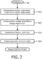
- FIG. 2 illustrates a flowchart representative of an exemplary embodiment of a robotic control method in accordance with the present disclosure.
- FIG. 3 illustrates an exemplary surgical implementation of the flowchart shown in FIG. 2 .
- FIG. 4 illustrates an exemplary embodiment of an anatomical feature delineation module in accordance with the present invention.
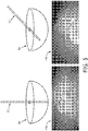
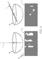
- FIGS. 5 and 6 illustrate exemplary implementations of an endoscope movement in accordance with the flowchart shown in FIG. 2 .
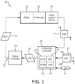
- a robotic guiding system employs a robot unit 10 and a control unit 20 for any endoscopic procedure involving an endoscopic imaging of one or more anatomical features of an anatomical region (e.
- endoscopic procedures include, but are not limited to, minimally invasive cardiac surgery, minimally invasive diagnostic interventions (e.g., arthoscopy), laparoscopic surgery, natural orifice transluminal surgery, single incision laparoscopic surgery and pulmonary/bronchoscopic surgery.
- the endoscopic imaging may be of any anatomical feature or section(s) therefore within any anatomical region. Nonetheless, to facilitate an understanding of the present invention, exemplary embodiments will be described in the context of an endoscopic imaging of a left anterior descending artery of a heart within a thorax region of a patient.
- Robot unit 10 includes a robot 11, an endoscope 12 rigidly attached to robot 11 and a video capture device 13 attached to the endoscope 12.
- Robot 11 is broadly defined herein as any robotic device structurally configured with motorized control of one or more joints for maneuvering an end-effector as desired for the particular endoscopic procedure.
- robot 11 may have four (4) degrees-of-freedom, such as, for example, a serial robot having joints serially connected with rigid segments, a parallel robot having joints and rigid segments mounted in parallel order (e.g., a Stewart platform known in the art) or any hybrid combination of serial and parallel kinematics.
- Endoscope 12 is broadly defined herein as any device structurally configured with ability to image from inside a body.
- Examples of endoscope 12 for purposes of the present invention include, but are not limited to, any type of scope, flexible or rigid (e.g., endoscope, arthroscope, bronchoscope, choledochoscope, colonoscope, cystoscope, duodenoscope, gastroscope, hysteroscope, laparoscope, laryngoscope, neuroscope, otoscope, push enteroscope, rhinolaryngoscope, sigmoidoscope, sinuscope, thorascope, etc.) and any device similar to a scope that is equipped with an image system (e.g., a nested cannula with imaging).
- the imaging is local, and surface images may be obtained optically with fiber optics, lenses, and miniaturized (e.g. CCD based) imaging systems.
- endoscope 12 is mounted to the end-effector of robot 11.
- a pose of the end-effector of robot 11 is a position and an orientation of the end-effector within a coordinate system of robot 11 actuators.
- any given pose of the field-of-view of endoscope 12 (i.e., endoscope pose) within an anatomical region corresponds to a distinct pose of the end-effector of robot 11 within the robotic coordinate system. Consequently, each individual endoscope image of the anatomical region generated by endoscope 12 may be linked to a corresponding pose of the field-of-view of endoscope 12 within the robotic coordinate system.
- Video capture device 13 is broadly defined herein as any device structurally configured with a capability to convert an endoscopic video signal from endoscope 12 into a computer readable temporal sequence of an endoscope image ("IOEI") 14.
- video capture device 13 may employ a frame grabber of any type for capturing individual digital still frames from the endoscopic video signal.
- control unit 20 includes a robot controller 21 and an endoscope controller 22.
- Robot controller 21 is broadly defined herein as any controller structurally configured to provide one or more robot actuator commands (“RAC”) 29 to robot 11 for controlling a pose of the end-effector of robot 11 as desired for the endoscopic procedure. More particularly, robot controller 21 converts endoscope position commands (“EPC") 28 from endoscope controller 22 into robot actuator commands 29.
- endoscope position commands 28 may indicate an endoscope path leading to desired three-dimensional position of a field-of-view of endoscope 12 within an anatomical region whereby robot controller 21 converts command 28 into commands 29 including an actuation current for each motor of robot 11 as needed to move endoscope 12 to the desired three-dimensional position of the field-of-view of endoscope 12 within an anatomical region.
- Endoscope controller 22 is broadly defined herein as any controller structurally configured for implementing a robotic control method in accordance with the present invention and exemplary shown in FIG. 2 .
- endoscope controller 22 may incorporate anatomical feature delineation module ("AFDM”) 23, an image registration module (“IRM”) 24, anatomical feature selection module (“AFSM”) 25 and a visual servo module (“VSM”) 26.
- AFDM atomical feature delineation module
- IRM image registration module
- AFSM atomical feature selection module
- VSM visual servo module
- Anatomical feature delineation module 23 is broadly defined herein as any module structurally configured for processing a user input (“UI") 27 to delineate a volume coordinate position (X, Y, Z) for each anatomical feature of interest thereof within a pre-operative image 43 of the anatomical region for an intra-operative visualization of the anatomical feature(s) within endoscope image 14.
- UI user input
- an anatomical feature delineation as exemplarily implemented by a stage S31 of flowchart 30 as shown in FIG. 2 .
- Image registration module 24 is broadly defined herein as any module structurally configured for registering pre-operative image 43 and endoscope image 14 as known in the art. In particular, an image registration as exemplarily implemented by a stage S32 of flowchart 30 shown in FIG. 2 .
- Anatomical feature selection module 25 is broadly defined herein as any module structurally configured for processing a user input 26 of a endoscopic viewing selection of a particular anatomical feature of interest or section(s).
- an anatomical feature selection exemplarily implemented by a stage S33 of flowchart 30 shown in FIG. 2 .
- the term "visualize” as used herein is broadly defined to describe a robotic control of endoscope 12 within an anatomical region whereby an anatomical feature of interest or section(s) thereof is either visible, partially or entirely, within endoscope image 14 or obstructed from being visible within endoscope image 14 yet susceptible to a surgeon forming a mental picture of an outline of the anatomical feature or section(s) thereof, partially or entirely, within endoscope image 14.
- Visual servo module 26 is broadly defined herein as any module structurally configured for determining and moving endoscope 12 to an endoscope pose within the anatomical region that facilitates a visualization of the selected anatomical feature(s) or section(s) thereof within endoscope image 14.
- an endoscope pose determination as exemplarily implemented by a stage S34 of flowchart 30 shown in FIG. 2 .
- a stage S31 of flowchart 30 encompasses anatomical feature delineation module 23 acquiring pre-operative image 43.
- an imaging device 41 e.g., a CT device, a MRI device, an X-ray device or a 3D US device
- Anatomical feature delineation module 23 may acquire pre-operative image 43 as pre-operative image 43 is being generated by imaging device 41 as exemplarily shown in FIG. 3 or as previously stored in a database 42 as exemplarily shown in FIG. 3 .
- Anatomical feature delineation module 23 processes pre-operative image 43 to delineate a volume coordinate position for each anatomical feature of interest or section(s) thereof within the anatomical region.
- anatomical feature delineation module 23 may execute any technique for delineating the anatomical feature(s) of interest or section(s) thereof within pre-operative image 43.
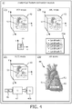
- anatomical feature delineation module 23 provides four (4) modes 23a-23d for delineating volume coordinate position(s) of anatomical feature(s) within pre-operative image 43.
- a volume coordinate position ("VCP") mode 23a delineates a volume coordinate position of each anatomical feature within pre-operative image 43 as selected by a user of module 23.
- pre-operative image has a 3D coordinate system defined by an X-axis, a Y-axis and a Z-axis.
- a user may move a cursor arrow to an anatomical feature of interest or section(s) thereof within pre-operative image 43 or a two-dimensional view 44 of the cursor within preoperative image 43 defined by a x-axis and a y-axis.
- the user may make a selection (e.g., a mouse click) of the anatomical feature or section(s) thereof facilitating a delineation of a volume coordinate position (X, Y, Z) of the anatomical feature.
- a selection e.g., a mouse click
- the user may be able to rotate pre-operative image 43 and corresponding two-dimensional view 44 of the cursor within preoperative image 43 to orient the anatomical feature for desired view in the endoscope image.
- an orientation of the anatomical feature is delineated with the volume coordinate position (X, Y, Z).
- the cursor movement and user selection may be repeated as desired for other areas of the selected anatomical feature and/or for additional anatomical features.
- a name may be assigned by the user to the selected anatomical feature(s) or section(s) thereof (e.g., "left anterior descending artery”). Particularly, when the user has interest in different sections of an anatomical feature (e.g., "upper section of left anterior descending artery", “middle section left anterior descending artery”, and “lower section of left anterior descending artery”).
- An anatomical feature landmark ("AFL") mode 23b provides a pre-defined listing 45a of landmark names for each anatomical feature or section(s) thereof within pre-operative image 43 for VCP mode 23a. Any landmark selected in listing 45a (e.g., left anterior descending artery as landmark 3) is highlighted within pre-operative image 43 via a cursor arrow. The user may move the cursor arrow relative to the highlighted anatomical feature to select section(s) of interest of the anatomical feature.
- Any landmark selected in listing 45a e.g., left anterior descending artery as landmark 3
- the user may move the cursor arrow relative to the highlighted anatomical feature to select section(s) of interest of the anatomical feature.
- the user may make a selection (e.g., a mouse click) of the anatomical feature facilitating a delineation of a volume coordinate position (X, Y, Z) and optional orientation of the anatomical feature or section thereof as described by VCP mode 23a and to name the anatomical feature, particularly selected section(s).
- a selection e.g., a mouse click
- a natural language interpretation mode (“NTLI”) 23c utilizes a text interpreter (“TI”) 47 to interpret natural language to generates a landmark listing 45b for VCP 23a.
- text interpreter 47 is used to interpret and convert free-text instructions generated during surgical planning to anatomical features which are then stored to be used to move endoscope 12 during the delineation process and/or endoscopic surgery.
- Anatomical descriptions are extracted into codes in a well-defined medical ontology (e.g., Systematized Nomenclature of Medicine (“SNOMED”) or the Foundational Model of Anatomy (“FMA”).
- SNOMED Systematized Nomenclature of Medicine
- FMA Foundational Model of Anatomy
- landmark listing 45b may be used in the same manner as landmark listing 45a to highlight anatomical features within pre-operative image 43 of the anatomical region for VCP mode 23a.
- Atlas registration ("AR") mode 23d involves a registration of an atlas of the anatomical region to pre-operative image 43 whereby each anatomical feature of the atlas are associated with a corresponding anatomical feature within the pre-operative image. Consequently, a user may utilize the atlas of the anatomical region to select and delineate anatomical features of interest or section(s) thereof analogous to VCP mode 23a.
- a registration of atlas 48 of the thorax region shown as a picture of the heart in FIG. 4
- pre-operative image 43 enables anatomical features of atlas 48 to be associated with corresponding anatomical features within pre-operative image 43 (e.g. left anterior descending artery 49 of atlas 48).
- a selection of an anatomical feature or section thereof of atlas 48 delineates a volume coordinate position and an optional orientation within pre-operative image 43.
- a stage S32 of flowchart 30 encompasses image registration module 24 acquiring and registering endoscope image 14 with pre-operative image 43 as known in the art.
- module 24 may implement a point based registration of endoscope image 14 with pre-operative image 43.
- module 24 may implement a graphical matching registration of endoscope image 14 with pre-operative image 43 involving a matching of graphical representations of anatomical features (e.g., blood vessel trees) in endoscope image 14 and pre-operative image 43.
- anatomical features e.g., blood vessel trees
- a stage S33 of flowchart 30 encompasses anatomical feature selection module 25 receiving a user input to VSM 26 ( FIG. 1 ) of an anatomical feature of interest or section thereof to facilitate a subsequent determination of an endoscope pose of endoscope 12 within the anatomical region for visualizing the anatomical feature or section thereof within endoscope image 14.
- module 25 may provide one or more views of the anatomical region in dependence of the mode ( FIG. 4 ) used to delineate the volume coordinate position and optional orientation of the anatomical features.
- marked or named anatomical features or section(s) thereof may be shown in an image of the anatomical region or a designed computer screen whereby the user may interact with image or the screen to select the anatomical feature or section thereof (e.g., a keyboard, a mouse, a touchscreen, a voice command, a gesture, etc.).
- the registered atlas may be presented whereby the user may interact with the atlas to select the anatomical feature or section thereof.
- a listing of landmark names may be presented to facilitate a selection of an anatomical feature or section thereof.
- a stage S34 of flowchart 30 encompasses visual servo module 26 determining an endoscope pose of endoscope 12 within the anatomical region for visualizing the selected anatomical feature or section thereof within endoscope image 14, and generating endoscope position commands 28 to robot controller 21 to thereby guide endoscope 12 ( FIG. 1 ) to the determined endoscope pose.
- the delineated volume coordinate position (X, Y, Z) within pre-operative image 43 corresponds to a frame coordinate position (x, y) within endoscope image 14 that provides for a visualization of the anatomical feature at volume coordinate position (X, Y, Z) (e.g., a center frame coordinate position of endoscope image 14) of pre-operative image 43.
- the frame coordinate position (x, y) may be oriented in accordance with a delineated endoscopic view orientation.
- endoscope 12 is calibrated (i.e., the endoscope camera parameters like focal length and optical center of endoscope image 14 are known), then a relationship between frame coordinate position (x, y) within endoscope image 14 and a pose of endoscope 12 within the anatomical region may be established as known in the art.
- the spatial transformation between endoscope 12 and joints of robot 11 is known from robot calibration procedures known in art, the relationship between the robot joints and image space may be derived. This relationship is referred to, in art, as Image Jacobian.
- robot joint values may be computed whereby, after robot 11 has moved endoscope 12 to the computed volume coordinate position (X. Y, Z), the anatomical feature is located at the desired frame coordinate position (x, y) of endoscope image 14 (e.g., a center of the image).
- uncalibrated visual servoing of robot 11 may be utilized to determine and move endoscope 12 to a pose within the anatomical region to visualize the anatomical feature or section thereof in accordance with the frame coordinate position (x, y) within endoscope image 14 (e.g., an uncalibrated velocity optimization method
- an anatomical feature 51 within an endoscope image 14a is covered by fat and obstructed from view. Nonetheless, once a surgeon picks the anatomical feature, endoscope 12 may be moved on a semi-sphere (touching the sphere) so that anatomical feature 51 goes in the middle of an endoscope image 14b. Note that endoscope 12 is pivoted around a fixed point based on distance between anatomical feature 51 as shown in images 14a and 14b.
- a selected anatomical feature 52 is outside the view of endoscope image 14c.
- Endoscope 12 may be moved again on a sphere 50 to anatomical feature 52 in the middle of endoscope image 14d. More particularly, an analogous distance between points within endoscope image 14c may serve to ascertain correction motion parameters for uncalibrated visual servoing of robot 11.
- stages S33 and S34 may be executed in a loop until such time robot 11 has moved endoscope 12 to each desired pose within the anatomical region.
- modules 23-26 may be implemented by hardware, software and/or firmware integrated within endoscope controller 22 as shown.
- Robot controller 21 and endoscope controller 22 may be physically separate controllers or logically controllers integrated within a single physical controller.
- FIGS. 1-6 From the description of FIGS. 1-6 herein, those having ordinary skill in the art will appreciate the numerous benefits of the present invention including, but not limited to, an application of the present invention to any type of endoscopy surgery involving a visualization of a particular anatomical feature or section thereof within an anatomical region.
Description
- The present invention generally relates to robotic control of an endoscope during a minimally invasive surgery (e.g., a minimally invasive coronary bypass grafting surgery). The present invention specifically relates to the robotic control being based upon a determination of an endoscope pose within the anatomical region for visualizing an anatomical feature within an endoscope image and in particular about the mode of inputting the endoscope pose into the robotic control.
- Minimally invasive surgery is performed using elongated instruments inserted into a patient's body through small ports. For a surgery involving an endoscope, an endoscopic camera is inserted into a port to provide visualization of the surgical site. For example, a surgeon may hold and manually control two (2) laparoscopic instruments during the surgery while a physician assistant controls the endoscope and receives instructions from the surgeon to move the endoscope to specific locations during the surgery.
- The surgeon's communication to the physician assistant of an exact desired location of the endoscope may be difficult, especially given the challenging hand-eye coordination required to move the endoscope and instruments around the pivot points at the entrance ports to the body, and given the different positions and frames of reference of the surgeon, physician assistant and a video image of the surgical site. For example, "Left" on the video image, may mean "right and down" at the physician assistant's hands. To overcome these difficulties, controlling the endoscope using an automated device or robot has been proposed in prior art, essentially removing the physician assistant from this task during surgery. However, given that the surgeon is controlling two (2) laparoscopic instruments with both hands, the method with which the physician can control the robotic endoscope is important, and a number of propositions have been addressed in prior art.
- Generally, the prior art methods for guiding a robotic system are premised on (1) guiding the robot using different input devices (e.g., head motion sensors, a joystick or voice control), (2) guiding the robot using live endoscope images by determining a three-dimensional position of an anatomical feature with respect to the endoscope and moving the endoscope or a surgical instrument toward that anatomical feature, or (3) guiding the robot from other types of images using live image and recorded intra-operative images A prior art robotic system for automatically moving the endoscope to a desired position and orientation to visualize an anatomical feature is disclosed in document
WO 2013/061225 . - More particularly, human-robot interaction methods known in art use either specialized hardware or live and/or recorded intra-operative images to move the robot to a desired location. These methods assume that the user knows location of the anatomical feature of interest with respect to the endoscope and that the particular anatomical feature is visible in the endoscope view. This is not always true, as the anatomical feature may be obstructed within the endoscope view (e.g., coronary arteries may be covered with fat) or may be outside of the endoscope view.
- The present invention provides a robotic control system that enables easy inputs of target positions or landmarks for delineating a volume coordinate position of an anatomical feature within a pre-operative image of the anatomical region to facilitate an intra-operative visualization of the anatomical feature within an endoscope image of the anatomical region, particularly for an anatomical feature partially or entirely invisible in the endoscope image (e.g., obstructed within endoscope view or outside of endoscope view).
- The term "visualize" or any variation thereof as used herein is broadly defined to describe a robotic control of an endoscope within an anatomical region whereby an anatomical feature of interest or section(s) therefore are either visible, partially or entirely, within the endoscope image or obstructed from being visible within the endoscope image yet susceptible to a surgeon forming a mental picture of an outline of the anatomical feature or section(s) thereof, partially or entirely, within the endoscope image.
- One form of the present invention is a robotic control system employing a robot uni as defined by
claim 1 and a control unit as defined by claim 8. The robot unit includes an endoscope for generating an endoscope image, and a robot for moving the endoscope within an anatomical region. The control unit includes an endoscope controller to determine an endoscope pose within the anatomical region for an intra-operative visualization of an anatomical feature within the endoscope image, wherein the endoscope pose is derived from a delineation of a volume coordinate position of the anatomical feature within a pre-operative image of the anatomical region. The control unit further includes a robot controller to command the robot to move the endoscope to the endoscope pose within the anatomical region to visualize the anatomical feature within the endoscope image The control unit is configured receive target location input via a landmark list or an atlas of the anatomic feature. - The term "pre-operative" as used herein is broadly defined to describe any activity executed before, during or after an endoscopic imaging of an anatomical region for purposes of acquiring a three-dimensional ("3D") image of the anatomical region. Examples of pre-operative imaging of the anatomical region includes, but are not limited to, computed tomography ("CT") imaging, magnetic resonance ("MR") imaging, X-ray imaging, and 3D ultrasound ("3D US") imaging before, during or after an endoscopic imaging of an anatomical region.
- The term "intra-operative" as used herein is broadly defined to describe any activity executed by the robot unit and/or the control unit during an endoscopic imaging of the anatomical region. Examples of endoscopic imaging of the anatomical region include, but are not limited to, a coronary artery bypass grafting, a bronchoscopy, a colonscopy, a laparascopy, and a brain endoscopy.
- Those having ordinary skill will appreciate the meaning of an "anatomical region" and an "anatomical feature" as known in the art. Nonetheless, examples of an anatomical region include, but are not limited to, head, neck, thorax, abdomen, back, pelvis and perineum. Also, examples of an anatomical feature include, but are not limited to, components and areas of an organ/organ system (e.g., blood vessels of a heart, a trachea of a respiratory system, a cerebellum of a brain, a fundus of a gallbladder, an area of a sigmoid colon).
- The foregoing forms and other forms of the present invention as well as various features and advantages of the present invention will become further apparent from the following detailed description of various embodiments of the present invention read in conjunction with the accompanying drawings. The detailed description and drawings are merely illustrative of the present invention rather than limiting, the scope of the present invention being defined by the appended claims and equivalents thereof.
-
FIG. 1 illustrates an exemplary embodiment of a robotic control system in accordance with the present disclosure. -
FIG. 2 illustrates a flowchart representative of an exemplary embodiment of a robotic control method in accordance with the present disclosure. -
FIG. 3 illustrates an exemplary surgical implementation of the flowchart shown inFIG. 2 . -
FIG. 4 illustrates an exemplary embodiment of an anatomical feature delineation module in accordance with the present invention. -
FIGS. 5 and6 illustrate exemplary implementations of an endoscope movement in accordance with the flowchart shown inFIG. 2 . - As shown in
FIG. 1 , a robotic guiding system employs arobot unit 10 and acontrol unit 20 for any endoscopic procedure involving an endoscopic imaging of one or more anatomical features of an anatomical region (e. Examples of such endoscopic procedures include, but are not limited to, minimally invasive cardiac surgery, minimally invasive diagnostic interventions (e.g., arthoscopy), laparoscopic surgery, natural orifice transluminal surgery, single incision laparoscopic surgery and pulmonary/bronchoscopic surgery. - In practice, the endoscopic imaging may be of any anatomical feature or section(s) therefore within any anatomical region. Nonetheless, to facilitate an understanding of the present invention, exemplary embodiments will be described in the context of an endoscopic imaging of a left anterior descending artery of a heart within a thorax region of a patient.
-
Robot unit 10 includes arobot 11, anendoscope 12 rigidly attached torobot 11 and avideo capture device 13 attached to theendoscope 12. - Robot 11 is broadly defined herein as any robotic device structurally configured with motorized control of one or more joints for maneuvering an end-effector as desired for the particular endoscopic procedure. In practice,
robot 11 may have four (4) degrees-of-freedom, such as, for example, a serial robot having joints serially connected with rigid segments, a parallel robot having joints and rigid segments mounted in parallel order (e.g., a Stewart platform known in the art) or any hybrid combination of serial and parallel kinematics. -
Endoscope 12 is broadly defined herein as any device structurally configured with ability to image from inside a body. Examples ofendoscope 12 for purposes of the present invention include, but are not limited to, any type of scope, flexible or rigid (e.g., endoscope, arthroscope, bronchoscope, choledochoscope, colonoscope, cystoscope, duodenoscope, gastroscope, hysteroscope, laparoscope, laryngoscope, neuroscope, otoscope, push enteroscope, rhinolaryngoscope, sigmoidoscope, sinuscope, thorascope, etc.) and any device similar to a scope that is equipped with an image system (e.g., a nested cannula with imaging). The imaging is local, and surface images may be obtained optically with fiber optics, lenses, and miniaturized (e.g. CCD based) imaging systems. - In practice,
endoscope 12 is mounted to the end-effector ofrobot 11. A pose of the end-effector ofrobot 11 is a position and an orientation of the end-effector within a coordinate system ofrobot 11 actuators. Withendoscope 12 mounted to the end-effector ofrobot 11, any given pose of the field-of-view of endoscope 12 (i.e., endoscope pose) within an anatomical region corresponds to a distinct pose of the end-effector ofrobot 11 within the robotic coordinate system. Consequently, each individual endoscope image of the anatomical region generated byendoscope 12 may be linked to a corresponding pose of the field-of-view ofendoscope 12 within the robotic coordinate system. -
Video capture device 13 is broadly defined herein as any device structurally configured with a capability to convert an endoscopic video signal fromendoscope 12 into a computer readable temporal sequence of an endoscope image ("IOEI") 14. In practice,video capture device 13 may employ a frame grabber of any type for capturing individual digital still frames from the endoscopic video signal. - Still referring to
FIG. 1 ,control unit 20 includes arobot controller 21 and anendoscope controller 22. -
Robot controller 21 is broadly defined herein as any controller structurally configured to provide one or more robot actuator commands ("RAC") 29 torobot 11 for controlling a pose of the end-effector ofrobot 11 as desired for the endoscopic procedure. More particularly,robot controller 21 converts endoscope position commands ("EPC") 28 fromendoscope controller 22 intorobot actuator commands 29. For example,endoscope position commands 28 may indicate an endoscope path leading to desired three-dimensional position of a field-of-view ofendoscope 12 within an anatomical region wherebyrobot controller 21 convertscommand 28 intocommands 29 including an actuation current for each motor ofrobot 11 as needed to moveendoscope 12 to the desired three-dimensional position of the field-of-view ofendoscope 12 within an anatomical region. -
Endoscope controller 22 is broadly defined herein as any controller structurally configured for implementing a robotic control method in accordance with the present invention and exemplary shown inFIG. 2 . To this end,endoscope controller 22 may incorporate anatomical feature delineation module ("AFDM") 23, an image registration module ("IRM") 24, anatomical feature selection module ("AFSM") 25 and a visual servo module ("VSM") 26. - Anatomical
feature delineation module 23 is broadly defined herein as any module structurally configured for processing a user input ("UI") 27 to delineate a volume coordinate position (X, Y, Z) for each anatomical feature of interest thereof within apre-operative image 43 of the anatomical region for an intra-operative visualization of the anatomical feature(s) withinendoscope image 14. In particular, an anatomical feature delineation as exemplarily implemented by a stage S31 offlowchart 30 as shown inFIG. 2 . -
Image registration module 24 is broadly defined herein as any module structurally configured for registering pre-operativeimage 43 andendoscope image 14 as known in the art. In particular, an image registration as exemplarily implemented by a stage S32 offlowchart 30 shown inFIG. 2 . - Anatomical
feature selection module 25 is broadly defined herein as any module structurally configured for processing auser input 26 of a endoscopic viewing selection of a particular anatomical feature of interest or section(s). In particular, an anatomical feature selection exemplarily implemented by a stage S33 offlowchart 30 shown inFIG. 2 . - Again, in context of
FIG. 1 , the term "visualize" as used herein is broadly defined to describe a robotic control ofendoscope 12 within an anatomical region whereby an anatomical feature of interest or section(s) thereof is either visible, partially or entirely, withinendoscope image 14 or obstructed from being visible withinendoscope image 14 yet susceptible to a surgeon forming a mental picture of an outline of the anatomical feature or section(s) thereof, partially or entirely, withinendoscope image 14. -
Visual servo module 26 is broadly defined herein as any module structurally configured for determining and movingendoscope 12 to an endoscope pose within the anatomical region that facilitates a visualization of the selected anatomical feature(s) or section(s) thereof withinendoscope image 14. In particular, an endoscope pose determination as exemplarily implemented by a stage S34 offlowchart 30 shown inFIG. 2 . - A description of
flowchart 30 will now be provided herein to facilitate a further understanding ofendoscope controller 22. - Referring to
FIG. 2 , a stage S31 offlowchart 30 encompasses anatomicalfeature delineation module 23 acquiringpre-operative image 43. For example, as shown inFIG. 3 , an imaging device 41 (e.g., a CT device, a MRI device, an X-ray device or a 3D US device) is operated to generatepre-operative image 43 of a thorax region of a patient 50 illustrating left and rightcoronary arteries patient 50. Anatomicalfeature delineation module 23 may acquirepre-operative image 43 aspre-operative image 43 is being generated by imagingdevice 41 as exemplarily shown inFIG. 3 or as previously stored in adatabase 42 as exemplarily shown inFIG. 3 . - Anatomical
feature delineation module 23 processespre-operative image 43 to delineate a volume coordinate position for each anatomical feature of interest or section(s) thereof within the anatomical region. In practice, anatomicalfeature delineation module 23 may execute any technique for delineating the anatomical feature(s) of interest or section(s) thereof withinpre-operative image 43. In one embodiment as shown inFIG. 4 , anatomicalfeature delineation module 23 provides four (4)modes 23a-23d for delineating volume coordinate position(s) of anatomical feature(s) withinpre-operative image 43. - Referring to
FIG. 4 , a volume coordinate position ("VCP")mode 23a delineates a volume coordinate position of each anatomical feature withinpre-operative image 43 as selected by a user ofmodule 23. Specifically, pre-operative image has a 3D coordinate system defined by an X-axis, a Y-axis and a Z-axis. A user may move a cursor arrow to an anatomical feature of interest or section(s) thereof withinpre-operative image 43 or a two-dimensional view 44 of the cursor withinpreoperative image 43 defined by a x-axis and a y-axis. Upon a desired positioning of the cursor, the user may make a selection (e.g., a mouse click) of the anatomical feature or section(s) thereof facilitating a delineation of a volume coordinate position (X, Y, Z) of the anatomical feature. Additionally, the user may be able to rotatepre-operative image 43 and corresponding two-dimensional view 44 of the cursor withinpreoperative image 43 to orient the anatomical feature for desired view in the endoscope image. In this case, an orientation of the anatomical feature is delineated with the volume coordinate position (X, Y, Z). The cursor movement and user selection may be repeated as desired for other areas of the selected anatomical feature and/or for additional anatomical features. - Furthermore, a name may be assigned by the user to the selected anatomical feature(s) or section(s) thereof (e.g., "left anterior descending artery"). Particularly, when the user has interest in different sections of an anatomical feature (e.g., "upper section of left anterior descending artery", "middle section left anterior descending artery", and "lower section of left anterior descending artery").
- An anatomical feature landmark ("AFL")
mode 23b provides a pre-defined listing 45a of landmark names for each anatomical feature or section(s) thereof withinpre-operative image 43 forVCP mode 23a. Any landmark selected in listing 45a (e.g., left anterior descending artery as landmark 3) is highlighted withinpre-operative image 43 via a cursor arrow. The user may move the cursor arrow relative to the highlighted anatomical feature to select section(s) of interest of the anatomical feature. Upon a desired positioning of the cursor, the user may make a selection (e.g., a mouse click) of the anatomical feature facilitating a delineation of a volume coordinate position (X, Y, Z) and optional orientation of the anatomical feature or section thereof as described byVCP mode 23a and to name the anatomical feature, particularly selected section(s). - A natural language interpretation mode ("NTLI") 23c utilizes a text interpreter ("TI") 47 to interpret natural language to generates a
landmark listing 45b forVCP 23a. Specifically,text interpreter 47 is used to interpret and convert free-text instructions generated during surgical planning to anatomical features which are then stored to be used to moveendoscope 12 during the delineation process and/or endoscopic surgery. Anatomical descriptions are extracted into codes in a well-defined medical ontology (e.g., Systematized Nomenclature of Medicine ("SNOMED") or the Foundational Model of Anatomy ("FMA"). - The following is an example of a free text report: "EKG showed nonspecific ST segment changes. Echocardiography showed a normal left ventricle with some mild hypertrophy. On diagnostic cardiac catheterization, a lesion to the left anterior descending artery was identified. There was about 80% stenosis in the circumflex system. The posterior descending artery had about a 70% stenosis. Bypass surgery recommended. " From this report,
text interpreter 47 extracts anatomical features: left anterior descending artery, circumflex system, posterior descending artery, etc. Further, from the ontology, thetext interpreter 47 may determine anatomical relationship between identified anatomy (e.g., left descending artery and left circumflex artery arise from the left main artery). Further, general location markers, such as "posterior" may be extracted and associated with a specific landmark. Thereafter,landmark listing 45b may be used in the same manner as landmark listing 45a to highlight anatomical features withinpre-operative image 43 of the anatomical region forVCP mode 23a. - Atlas registration ("AR")
mode 23d involves a registration of an atlas of the anatomical region topre-operative image 43 whereby each anatomical feature of the atlas are associated with a corresponding anatomical feature within the pre-operative image. Consequently, a user may utilize the atlas of the anatomical region to select and delineate anatomical features of interest or section(s) thereof analogous toVCP mode 23a. For example, a registration ofatlas 48 of the thorax region (shown as a picture of the heart inFIG. 4 ) topre-operative image 43 enables anatomical features ofatlas 48 to be associated with corresponding anatomical features within pre-operative image 43 (e.g. left anterior descendingartery 49 of atlas 48). Thus, a selection of an anatomical feature or section thereof ofatlas 48 delineates a volume coordinate position and an optional orientation withinpre-operative image 43. - Referring back to
FIG. 2 , a stage S32 offlowchart 30 encompassesimage registration module 24 acquiring and registeringendoscope image 14 withpre-operative image 43 as known in the art. In one embodiment,module 24 may implement a point based registration ofendoscope image 14 withpre-operative image 43. In another embodiment,module 24 may implement a graphical matching registration ofendoscope image 14 withpre-operative image 43 involving a matching of graphical representations of anatomical features (e.g., blood vessel trees) inendoscope image 14 andpre-operative image 43. - Upon completion of stage S32, a stage S33 of
flowchart 30 encompasses anatomicalfeature selection module 25 receiving a user input to VSM 26 (FIG. 1 ) of an anatomical feature of interest or section thereof to facilitate a subsequent determination of an endoscope pose ofendoscope 12 within the anatomical region for visualizing the anatomical feature or section thereof withinendoscope image 14. In practice,module 25 may provide one or more views of the anatomical region in dependence of the mode (FIG. 4 ) used to delineate the volume coordinate position and optional orientation of the anatomical features. For example, marked or named anatomical features or section(s) thereof may be shown in an image of the anatomical region or a designed computer screen whereby the user may interact with image or the screen to select the anatomical feature or section thereof (e.g., a keyboard, a mouse, a touchscreen, a voice command, a gesture, etc.). Also by example, the registered atlas may be presented whereby the user may interact with the atlas to select the anatomical feature or section thereof. By further example, a listing of landmark names may be presented to facilitate a selection of an anatomical feature or section thereof. - Still referring to
FIG. 2 , a stage S34 offlowchart 30 encompassesvisual servo module 26 determining an endoscope pose ofendoscope 12 within the anatomical region for visualizing the selected anatomical feature or section thereof withinendoscope image 14, and generating endoscope position commands 28 torobot controller 21 to thereby guide endoscope 12 (FIG. 1 ) to the determined endoscope pose. - Specifically, from the image registration of stage S32 and the anatomical feature selection of stage S33, the delineated volume coordinate position (X, Y, Z) within
pre-operative image 43 corresponds to a frame coordinate position (x, y) withinendoscope image 14 that provides for a visualization of the anatomical feature at volume coordinate position (X, Y, Z) (e.g., a center frame coordinate position of endoscope image 14) ofpre-operative image 43. Additionally, the frame coordinate position (x, y) may be oriented in accordance with a delineated endoscopic view orientation. - If
endoscope 12 is calibrated (i.e., the endoscope camera parameters like focal length and optical center ofendoscope image 14 are known), then a relationship between frame coordinate position (x, y) withinendoscope image 14 and a pose ofendoscope 12 within the anatomical region may be established as known in the art. Assuming further that the spatial transformation betweenendoscope 12 and joints ofrobot 11 is known from robot calibration procedures known in art, the relationship between the robot joints and image space may be derived. This relationship is referred to, in art, as Image Jacobian. From the Image Jacobian, robot joint values may be computed whereby, afterrobot 11 has movedendoscope 12 to the computed volume coordinate position (X. Y, Z), the anatomical feature is located at the desired frame coordinate position (x, y) of endoscope image 14 (e.g., a center of the image). - If
endoscope 12 is not calibrated and/or the transformation between theendoscope 12 and joints ofrobot 11 is not known, then uncalibrated visual servoing ofrobot 11 as known in the art may be utilized to determine and moveendoscope 12 to a pose within the anatomical region to visualize the anatomical feature or section thereof in accordance with the frame coordinate position (x, y) within endoscope image 14 (e.g., an uncalibrated velocity optimization method - For example, referring to
FIG. 5 , ananatomical feature 51 within anendoscope image 14a is covered by fat and obstructed from view. Nonetheless, once a surgeon picks the anatomical feature,endoscope 12 may be moved on a semi-sphere (touching the sphere) so thatanatomical feature 51 goes in the middle of anendoscope image 14b. Note thatendoscope 12 is pivoted around a fixed point based on distance betweenanatomical feature 51 as shown inimages - By further example, referring to
FIG. 6 , a selectedanatomical feature 52 is outside the view ofendoscope image 14c.Endoscope 12 may be moved again on asphere 50 toanatomical feature 52 in the middle ofendoscope image 14d. More particularly, an analogous distance between points withinendoscope image 14c may serve to ascertain correction motion parameters for uncalibrated visual servoing ofrobot 11. - Referring back to
FIG. 2 , stages S33 and S34 may be executed in a loop untilsuch time robot 11 has movedendoscope 12 to each desired pose within the anatomical region. - In practice, modules 23-26 (
FIG. 1 ) may be implemented by hardware, software and/or firmware integrated withinendoscope controller 22 as shown. -
Robot controller 21 andendoscope controller 22 may be physically separate controllers or logically controllers integrated within a single physical controller. - From the description of
FIGS. 1-6 herein, those having ordinary skill in the art will appreciate the numerous benefits of the present invention including, but not limited to, an application of the present invention to any type of endoscopy surgery involving a visualization of a particular anatomical feature or section thereof within an anatomical region. - Although the present invention has been described with reference to exemplary aspects, features and implementations, the disclosed systems and methods are not limited to such exemplary aspects, features and/or implementations. Rather, as will be readily apparent to persons skilled in the art from the description provided herein, the disclosed systems and methods are susceptible to modifications, alterations and enhancements without departing from the scope of the present invention. Accordingly, the present invention expressly encompasses such modification, alterations and enhancements within the scope hereof.
Claims (11)
- A robotic control system, comprising:a robot unit (10) includingan endoscope (12) operable to generate an endoscope image (14), anda robot (11) operable to move the endoscope (12) within an anatomical region; anda control unit (20) includingcharacterised in that the endoscope controller (22) is further operable to a) provide a listing (45a) of landmark names of the anatomical region to facilitate a delineation of the volume coordinate position of the anatomical feature, and/or b) provide an atlas (48) of the anatomical region registered to the pre-operative image (43) to facilitate a delineation of the volume coordinate position of the anatomical feature within the pre-operative image (43) of the anatomical region, whereby each anatomical feature of the atlas (48) is associated with a corresponding anatomical feature within the pre-operative image (43), and allow a user to select an anatomical feature of the atlas (48) for delineating the volume coordinate position of the anatomical feature with the pre-operative image.an endoscope controller (22) operable to determine an endoscope pose within the anatomical region for an intra-operative visualization of an anatomical feature within the endoscope image (14),
wherein the endoscope pose is derived from a delineation of a volume coordinate position of the anatomical feature within a pre-operative image (43) of the anatomical region, anda robot controller (21) operable to command the robot (11) to move the endoscope (12) to the endoscope pose within the anatomical region to visualize the anatomical feature within the endoscope image (14), - The robotic control system of claim 1, wherein the endoscope controller (22) is further operable to provide a description of the anatomical feature to facilitate a selection of the anatomical feature for visualization in the endoscope image (14).
- The robotic control system of claim 2, the description of the anatomical feature includes at least one of a landmark name and a code of the anatomical feature.
- The robotic control system of claim 1, wherein the endoscope pose is further derived from a delineation of an endoscopic view orientation of the anatomical feature within the pre-operative image (43) of the anatomical region.
- The robotic control system of claim 1, wherein the endoscope controller (22) is further operable to interpret natural language surgical instructions for the anatomical region to facilitate a delineation of the volume coordinate position of the anatomical feature.
- The robotic control system of claim 1, wherein the endoscope controller (22) is further operable to translate the volume coordinate position (X, Y, Z) of the anatomical feature within the pre-operative image (43) to a frame coordinate position (x, y) of the anatomical feature within the endoscope image (14).
- A control unit (20) for an endoscope (12) operable to generate an endoscope image (14) and a robot (11) operable to move the endoscope (12) within an anatomical region, the control unit (20) comprising:an endoscope controller (22) operable to determine an endoscope pose within the anatomical region for an intra-operative visualization of an anatomical feature within the endoscope image (14),
wherein the endoscope pose is derived from a delineation of a volume coordinate position of the anatomical feature within a pre-operative image (43) of the anatomical region; anda robot controller (21) operable to command the robot (11) to move the endoscope (12) to the endoscope pose within the anatomical region to visualize the anatomical feature within the endoscope image (14);characterised in that the endoscope controller (22) is further operable to a) provide a listing (45a) of landmark names of the anatomical region to facilitate a delineation of the volume coordinate position of the anatomical feature, and/or b) provide an atlas (48) of the anatomical region registered to the pre-operative image (43) to facilitate a delineation of the volume coordinate position of the anatomical feature within the pre-operative image (43) of the anatomical region, whereby each anatomical feature of the atlas (48) is associated with a corresponding anatomical feature within the pre-operative image (43), and allow a user to select an anatomical feature of the atlas (48) for delineating the volume coordinate position of the anatomical feature with the pre-operative image. - The control unit (20) of claim 7, wherein the endoscope controller (22) is further operable to provide a description of the anatomical feature to facilitate a selection of the anatomical feature for visualization within the endoscope image (14).
- The control unit (20) of claim 7, wherein the endoscope pose is further derived from a delineation of an endoscopic view orientation of the anatomical feature within the pre-operative image (43) of the anatomical region.
- The control unit (20) of claim 7, wherein the endoscope controller (22) is further operable to interpret natural language surgical instructions for the anatomical region to facilitate a delineation of the volume coordinate position of the anatomical feature.
- The control unit (20) of claim 7, wherein the endoscope controller (22) is further operable to translate the volume coordinate position (X, Y, Z) of the anatomical feature within the pre-operative image (43) to a frame coordinate position (x, y) of the anatomical feature within the endoscope image (14).
Applications Claiming Priority (2)
| Application Number | Priority Date | Filing Date | Title |
|---|---|---|---|
| US201361821363P | 2013-05-09 | 2013-05-09 | |
| PCT/IB2014/061100 WO2014181222A1 (en) | 2013-05-09 | 2014-04-30 | Robotic control of an endoscope from anatomical features |
Publications (2)
| Publication Number | Publication Date |
|---|---|
| EP2996617A1 EP2996617A1 (en) | 2016-03-23 |
| EP2996617B1 true EP2996617B1 (en) | 2021-04-14 |
Family
ID=50841905
Family Applications (1)
| Application Number | Title | Priority Date | Filing Date |
|---|---|---|---|
| EP14727057.3A Active EP2996617B1 (en) | 2013-05-09 | 2014-04-30 | Robotic control of an endoscope from anatomical features |
Country Status (6)
| Country | Link |
|---|---|
| US (1) | US11284777B2 (en) |
| EP (1) | EP2996617B1 (en) |
| JP (1) | JP6629186B2 (en) |
| CN (1) | CN105188594B (en) |
| RU (1) | RU2692206C2 (en) |
| WO (1) | WO2014181222A1 (en) |
Families Citing this family (13)
| Publication number | Priority date | Publication date | Assignee | Title |
|---|---|---|---|---|
| US10248756B2 (en) * | 2015-02-18 | 2019-04-02 | Siemens Healthcare Gmbh | Anatomically specific movie driven medical image review |
| WO2017013521A1 (en) | 2015-07-23 | 2017-01-26 | Koninklijke Philips N.V. | Endoscope guidance from interactive planar slices of a volume image |
| US11638615B2 (en) * | 2015-08-30 | 2023-05-02 | Asensus Surgical Us, Inc. | Intelligent surgical tool control system for laparoscopic surgeries |
| EP3397186A1 (en) * | 2015-12-29 | 2018-11-07 | Koninklijke Philips N.V. | Image guided robotic convergent ablation |
| CN105788390A (en) * | 2016-04-29 | 2016-07-20 | 吉林医药学院 | Medical anatomy auxiliary teaching system based on augmented reality |
| WO2018104252A1 (en) * | 2016-12-07 | 2018-06-14 | Koninklijke Philips N.V. | Image guided motion scaling for robot control |
| US11696814B2 (en) | 2017-02-28 | 2023-07-11 | Sony Corporation | Medical arm system, control device, and control method |
| WO2018189742A1 (en) * | 2017-04-13 | 2018-10-18 | V.T.M. (Virtual Tape Measure) Technologies Ltd. | Endoscopic measurement methods and tools |
| CN107049496B (en) * | 2017-05-22 | 2019-07-26 | 清华大学 | A kind of Visual servoing control method of multitask operating robot |
| EP3705018A4 (en) * | 2017-11-01 | 2020-10-14 | Sony Corporation | Surgical arm system and surgical arm control system |
| US10672510B1 (en) | 2018-11-13 | 2020-06-02 | Biosense Webster (Israel) Ltd. | Medical user interface |
| CN111798387A (en) * | 2020-06-24 | 2020-10-20 | 海南大学 | Image processing method and system for confocal endoscope |
| USD1022197S1 (en) | 2020-11-19 | 2024-04-09 | Auris Health, Inc. | Endoscope |
Citations (3)
| Publication number | Priority date | Publication date | Assignee | Title |
|---|---|---|---|---|
| US20100256558A1 (en) * | 2008-03-27 | 2010-10-07 | Olson Eric S | Robotic catheter system |
| DE102011082444A1 (en) * | 2011-09-09 | 2012-12-20 | Siemens Aktiengesellschaft | Image-supported navigation method of e.g. endoscope used in medical intervention of human body, involves registering and representing captured image with 3D data set by optical detection system |
| WO2013061225A1 (en) * | 2011-10-26 | 2013-05-02 | Koninklijke Philips Electronics N.V. | Endoscopic registration of vessel tree images |
Family Cites Families (15)
| Publication number | Priority date | Publication date | Assignee | Title |
|---|---|---|---|---|
| US6379302B1 (en) * | 1999-10-28 | 2002-04-30 | Surgical Navigation Technologies Inc. | Navigation information overlay onto ultrasound imagery |
| US6584339B2 (en) * | 2001-06-27 | 2003-06-24 | Vanderbilt University | Method and apparatus for collecting and processing physical space data for use while performing image-guided surgery |
| US20060271056A1 (en) * | 2005-05-10 | 2006-11-30 | Smith & Nephew, Inc. | System and method for modular navigated osteotome |
| US8398541B2 (en) | 2006-06-06 | 2013-03-19 | Intuitive Surgical Operations, Inc. | Interactive user interfaces for robotic minimally invasive surgical systems |
| AU2007254158A1 (en) | 2006-05-19 | 2007-11-29 | Mako Surgical Corp. | Method and apparatus for controlling a haptic device |
| US8660635B2 (en) * | 2006-09-29 | 2014-02-25 | Medtronic, Inc. | Method and apparatus for optimizing a computer assisted surgical procedure |
| CA2670261A1 (en) | 2006-11-16 | 2008-05-29 | Vanderbilt University | Apparatus and methods of compensating for organ deformation, registration of internal structures to images, and applications of same |
| US8337397B2 (en) * | 2009-03-26 | 2012-12-25 | Intuitive Surgical Operations, Inc. | Method and system for providing visual guidance to an operator for steering a tip of an endoscopic device toward one or more landmarks in a patient |
| IT1395018B1 (en) | 2009-07-22 | 2012-09-05 | Surgica Robotica S R L | EQUIPMENT FOR MINIMUM INVASIVE SURGICAL PROCEDURES |
| JP2011156203A (en) * | 2010-02-02 | 2011-08-18 | Olympus Corp | Image processor, endoscope system, program, and image processing method |
| JP5675227B2 (en) * | 2010-08-31 | 2015-02-25 | 富士フイルム株式会社 | Endoscopic image processing apparatus, operation method, and program |
| US9615886B2 (en) | 2010-09-15 | 2017-04-11 | Koninklijke Philips N.V. | Robotic control of an endoscope from blood vessel tree images |
| US20140039314A1 (en) | 2010-11-11 | 2014-02-06 | The Johns Hopkins University | Remote Center of Motion Robot for Medical Image Scanning and Image-Guided Targeting |
| SG190383A1 (en) * | 2010-11-26 | 2013-06-28 | Agency Science Tech & Res | Method for creating a report from radiological images using electronic report templates |
| KR20120109890A (en) * | 2011-03-28 | 2012-10-09 | 삼성디스플레이 주식회사 | Driving apparatus and driving method of liquid crsytal display |
-
2014
- 2014-04-30 RU RU2015152452A patent/RU2692206C2/en active
- 2014-04-30 US US14/889,897 patent/US11284777B2/en active Active
- 2014-04-30 JP JP2016512453A patent/JP6629186B2/en active Active
- 2014-04-30 CN CN201480026577.8A patent/CN105188594B/en active Active
- 2014-04-30 WO PCT/IB2014/061100 patent/WO2014181222A1/en active Application Filing
- 2014-04-30 EP EP14727057.3A patent/EP2996617B1/en active Active
Patent Citations (3)
| Publication number | Priority date | Publication date | Assignee | Title |
|---|---|---|---|---|
| US20100256558A1 (en) * | 2008-03-27 | 2010-10-07 | Olson Eric S | Robotic catheter system |
| DE102011082444A1 (en) * | 2011-09-09 | 2012-12-20 | Siemens Aktiengesellschaft | Image-supported navigation method of e.g. endoscope used in medical intervention of human body, involves registering and representing captured image with 3D data set by optical detection system |
| WO2013061225A1 (en) * | 2011-10-26 | 2013-05-02 | Koninklijke Philips Electronics N.V. | Endoscopic registration of vessel tree images |
Also Published As
| Publication number | Publication date |
|---|---|
| EP2996617A1 (en) | 2016-03-23 |
| RU2692206C2 (en) | 2019-06-21 |
| RU2015152452A3 (en) | 2018-03-28 |
| US20160066768A1 (en) | 2016-03-10 |
| JP6629186B2 (en) | 2020-01-15 |
| CN105188594B (en) | 2021-02-09 |
| JP2016524487A (en) | 2016-08-18 |
| CN105188594A (en) | 2015-12-23 |
| RU2015152452A (en) | 2017-06-15 |
| US11284777B2 (en) | 2022-03-29 |
| WO2014181222A1 (en) | 2014-11-13 |
Similar Documents
| Publication | Publication Date | Title |
|---|---|---|
| EP2996617B1 (en) | Robotic control of an endoscope from anatomical features | |
| US10182704B2 (en) | Robotic control of an endoscope from blood vessel tree images | |
| US11759266B2 (en) | Robotic systems for determining a roll of a medical device in luminal networks | |
| US9280823B2 (en) | Invisible bifurcation detection within vessel tree images | |
| US10453174B2 (en) | Endoscopic registration of vessel tree images | |
| EP2838412B1 (en) | Guidance tools to manually steer endoscope using pre-operative and intra-operative 3d images | |
| US20190069955A1 (en) | Control unit, system and method for controlling hybrid robot having rigid proximal portion and flexible distal portion | |
| WO2012156873A1 (en) | Endoscope segmentation correction for 3d-2d image overlay |
Legal Events
| Date | Code | Title | Description |
|---|---|---|---|
| PUAI | Public reference made under article 153(3) epc to a published international application that has entered the european phase |
Free format text: ORIGINAL CODE: 0009012 |
|
| 17P | Request for examination filed |
Effective date: 20151209 |
|
| AK | Designated contracting states |
Kind code of ref document: A1 Designated state(s): AL AT BE BG CH CY CZ DE DK EE ES FI FR GB GR HR HU IE IS IT LI LT LU LV MC MK MT NL NO PL PT RO RS SE SI SK SM TR |
|
| AX | Request for extension of the european patent |
Extension state: BA ME |
|
| DAX | Request for extension of the european patent (deleted) | ||
| STAA | Information on the status of an ep patent application or granted ep patent |
Free format text: STATUS: EXAMINATION IS IN PROGRESS |
|
| 17Q | First examination report despatched |
Effective date: 20170410 |
|
| RAP1 | Party data changed (applicant data changed or rights of an application transferred) |
Owner name: KONINKLIJKE PHILIPS N.V. |
|
| GRAP | Despatch of communication of intention to grant a patent |
Free format text: ORIGINAL CODE: EPIDOSNIGR1 |
|
| STAA | Information on the status of an ep patent application or granted ep patent |
Free format text: STATUS: GRANT OF PATENT IS INTENDED |
|
| INTG | Intention to grant announced |
Effective date: 20201120 |
|
| GRAS | Grant fee paid |
Free format text: ORIGINAL CODE: EPIDOSNIGR3 |
|
| GRAA | (expected) grant |
Free format text: ORIGINAL CODE: 0009210 |
|
| STAA | Information on the status of an ep patent application or granted ep patent |
Free format text: STATUS: THE PATENT HAS BEEN GRANTED |
|
| AK | Designated contracting states |
Kind code of ref document: B1 Designated state(s): AL AT BE BG CH CY CZ DE DK EE ES FI FR GB GR HR HU IE IS IT LI LT LU LV MC MK MT NL NO PL PT RO RS SE SI SK SM TR |
|
| REG | Reference to a national code |
Ref country code: GB Ref legal event code: FG4D |
|
| REG | Reference to a national code |
Ref country code: CH Ref legal event code: EP |
|
| REG | Reference to a national code |
Ref country code: DE Ref legal event code: R096 Ref document number: 602014076563 Country of ref document: DE |
|
| REG | Reference to a national code |
Ref country code: IE Ref legal event code: FG4D |
|
| REG | Reference to a national code |
Ref country code: AT Ref legal event code: REF Ref document number: 1381592 Country of ref document: AT Kind code of ref document: T Effective date: 20210515 |
|
| REG | Reference to a national code |
Ref country code: LT Ref legal event code: MG9D |
|
| REG | Reference to a national code |
Ref country code: AT Ref legal event code: MK05 Ref document number: 1381592 Country of ref document: AT Kind code of ref document: T Effective date: 20210414 |
|
| REG | Reference to a national code |
Ref country code: NL Ref legal event code: MP Effective date: 20210414 |
|
| PG25 | Lapsed in a contracting state [announced via postgrant information from national office to epo] |
Ref country code: HR Free format text: LAPSE BECAUSE OF FAILURE TO SUBMIT A TRANSLATION OF THE DESCRIPTION OR TO PAY THE FEE WITHIN THE PRESCRIBED TIME-LIMIT Effective date: 20210414 Ref country code: FI Free format text: LAPSE BECAUSE OF FAILURE TO SUBMIT A TRANSLATION OF THE DESCRIPTION OR TO PAY THE FEE WITHIN THE PRESCRIBED TIME-LIMIT Effective date: 20210414 Ref country code: NL Free format text: LAPSE BECAUSE OF FAILURE TO SUBMIT A TRANSLATION OF THE DESCRIPTION OR TO PAY THE FEE WITHIN THE PRESCRIBED TIME-LIMIT Effective date: 20210414 Ref country code: LT Free format text: LAPSE BECAUSE OF FAILURE TO SUBMIT A TRANSLATION OF THE DESCRIPTION OR TO PAY THE FEE WITHIN THE PRESCRIBED TIME-LIMIT Effective date: 20210414 Ref country code: AT Free format text: LAPSE BECAUSE OF FAILURE TO SUBMIT A TRANSLATION OF THE DESCRIPTION OR TO PAY THE FEE WITHIN THE PRESCRIBED TIME-LIMIT Effective date: 20210414 Ref country code: BG Free format text: LAPSE BECAUSE OF FAILURE TO SUBMIT A TRANSLATION OF THE DESCRIPTION OR TO PAY THE FEE WITHIN THE PRESCRIBED TIME-LIMIT Effective date: 20210714 |
|
| PG25 | Lapsed in a contracting state [announced via postgrant information from national office to epo] |
Ref country code: GR Free format text: LAPSE BECAUSE OF FAILURE TO SUBMIT A TRANSLATION OF THE DESCRIPTION OR TO PAY THE FEE WITHIN THE PRESCRIBED TIME-LIMIT Effective date: 20210715 Ref country code: IS Free format text: LAPSE BECAUSE OF FAILURE TO SUBMIT A TRANSLATION OF THE DESCRIPTION OR TO PAY THE FEE WITHIN THE PRESCRIBED TIME-LIMIT Effective date: 20210814 Ref country code: LV Free format text: LAPSE BECAUSE OF FAILURE TO SUBMIT A TRANSLATION OF THE DESCRIPTION OR TO PAY THE FEE WITHIN THE PRESCRIBED TIME-LIMIT Effective date: 20210414 Ref country code: PL Free format text: LAPSE BECAUSE OF FAILURE TO SUBMIT A TRANSLATION OF THE DESCRIPTION OR TO PAY THE FEE WITHIN THE PRESCRIBED TIME-LIMIT Effective date: 20210414 Ref country code: NO Free format text: LAPSE BECAUSE OF FAILURE TO SUBMIT A TRANSLATION OF THE DESCRIPTION OR TO PAY THE FEE WITHIN THE PRESCRIBED TIME-LIMIT Effective date: 20210714 Ref country code: PT Free format text: LAPSE BECAUSE OF FAILURE TO SUBMIT A TRANSLATION OF THE DESCRIPTION OR TO PAY THE FEE WITHIN THE PRESCRIBED TIME-LIMIT Effective date: 20210816 Ref country code: ES Free format text: LAPSE BECAUSE OF FAILURE TO SUBMIT A TRANSLATION OF THE DESCRIPTION OR TO PAY THE FEE WITHIN THE PRESCRIBED TIME-LIMIT Effective date: 20210414 Ref country code: SE Free format text: LAPSE BECAUSE OF FAILURE TO SUBMIT A TRANSLATION OF THE DESCRIPTION OR TO PAY THE FEE WITHIN THE PRESCRIBED TIME-LIMIT Effective date: 20210414 Ref country code: RS Free format text: LAPSE BECAUSE OF FAILURE TO SUBMIT A TRANSLATION OF THE DESCRIPTION OR TO PAY THE FEE WITHIN THE PRESCRIBED TIME-LIMIT Effective date: 20210414 |
|
| PG25 | Lapsed in a contracting state [announced via postgrant information from national office to epo] |
Ref country code: LU Free format text: LAPSE BECAUSE OF NON-PAYMENT OF DUE FEES Effective date: 20210430 |
|
| REG | Reference to a national code |
Ref country code: DE Ref legal event code: R097 Ref document number: 602014076563 Country of ref document: DE |
|
| REG | Reference to a national code |
Ref country code: BE Ref legal event code: MM Effective date: 20210430 |
|
| PG25 | Lapsed in a contracting state [announced via postgrant information from national office to epo] |
Ref country code: RO Free format text: LAPSE BECAUSE OF FAILURE TO SUBMIT A TRANSLATION OF THE DESCRIPTION OR TO PAY THE FEE WITHIN THE PRESCRIBED TIME-LIMIT Effective date: 20210414 Ref country code: MC Free format text: LAPSE BECAUSE OF FAILURE TO SUBMIT A TRANSLATION OF THE DESCRIPTION OR TO PAY THE FEE WITHIN THE PRESCRIBED TIME-LIMIT Effective date: 20210414 Ref country code: LI Free format text: LAPSE BECAUSE OF NON-PAYMENT OF DUE FEES Effective date: 20210430 Ref country code: CH Free format text: LAPSE BECAUSE OF NON-PAYMENT OF DUE FEES Effective date: 20210430 Ref country code: CZ Free format text: LAPSE BECAUSE OF FAILURE TO SUBMIT A TRANSLATION OF THE DESCRIPTION OR TO PAY THE FEE WITHIN THE PRESCRIBED TIME-LIMIT Effective date: 20210414 Ref country code: EE Free format text: LAPSE BECAUSE OF FAILURE TO SUBMIT A TRANSLATION OF THE DESCRIPTION OR TO PAY THE FEE WITHIN THE PRESCRIBED TIME-LIMIT Effective date: 20210414 Ref country code: DK Free format text: LAPSE BECAUSE OF FAILURE TO SUBMIT A TRANSLATION OF THE DESCRIPTION OR TO PAY THE FEE WITHIN THE PRESCRIBED TIME-LIMIT Effective date: 20210414 Ref country code: SM Free format text: LAPSE BECAUSE OF FAILURE TO SUBMIT A TRANSLATION OF THE DESCRIPTION OR TO PAY THE FEE WITHIN THE PRESCRIBED TIME-LIMIT Effective date: 20210414 Ref country code: SK Free format text: LAPSE BECAUSE OF FAILURE TO SUBMIT A TRANSLATION OF THE DESCRIPTION OR TO PAY THE FEE WITHIN THE PRESCRIBED TIME-LIMIT Effective date: 20210414 |
|
| PLBE | No opposition filed within time limit |
Free format text: ORIGINAL CODE: 0009261 |
|
| STAA | Information on the status of an ep patent application or granted ep patent |
Free format text: STATUS: NO OPPOSITION FILED WITHIN TIME LIMIT |
|
| 26N | No opposition filed |
Effective date: 20220117 |
|
| PG25 | Lapsed in a contracting state [announced via postgrant information from national office to epo] |
Ref country code: IE Free format text: LAPSE BECAUSE OF NON-PAYMENT OF DUE FEES Effective date: 20210430 |
|
| PG25 | Lapsed in a contracting state [announced via postgrant information from national office to epo] |
Ref country code: IS Free format text: LAPSE BECAUSE OF FAILURE TO SUBMIT A TRANSLATION OF THE DESCRIPTION OR TO PAY THE FEE WITHIN THE PRESCRIBED TIME-LIMIT Effective date: 20210814 Ref country code: AL Free format text: LAPSE BECAUSE OF FAILURE TO SUBMIT A TRANSLATION OF THE DESCRIPTION OR TO PAY THE FEE WITHIN THE PRESCRIBED TIME-LIMIT Effective date: 20210414 |
|
| PG25 | Lapsed in a contracting state [announced via postgrant information from national office to epo] |
Ref country code: IT Free format text: LAPSE BECAUSE OF FAILURE TO SUBMIT A TRANSLATION OF THE DESCRIPTION OR TO PAY THE FEE WITHIN THE PRESCRIBED TIME-LIMIT Effective date: 20210414 Ref country code: BE Free format text: LAPSE BECAUSE OF NON-PAYMENT OF DUE FEES Effective date: 20210430 |
|
| PG25 | Lapsed in a contracting state [announced via postgrant information from national office to epo] |
Ref country code: HU Free format text: LAPSE BECAUSE OF FAILURE TO SUBMIT A TRANSLATION OF THE DESCRIPTION OR TO PAY THE FEE WITHIN THE PRESCRIBED TIME-LIMIT; INVALID AB INITIO Effective date: 20140430 |
|
| PG25 | Lapsed in a contracting state [announced via postgrant information from national office to epo] |
Ref country code: CY Free format text: LAPSE BECAUSE OF FAILURE TO SUBMIT A TRANSLATION OF THE DESCRIPTION OR TO PAY THE FEE WITHIN THE PRESCRIBED TIME-LIMIT Effective date: 20210414 |
|
| PGFP | Annual fee paid to national office [announced via postgrant information from national office to epo] |
Ref country code: FR Payment date: 20230421 Year of fee payment: 10 Ref country code: DE Payment date: 20220628 Year of fee payment: 10 |
|
| PGFP | Annual fee paid to national office [announced via postgrant information from national office to epo] |
Ref country code: GB Payment date: 20230418 Year of fee payment: 10 |