EP2995932B1 - Fibre optique avec un canal creux le long de l'àme du fibre optique pour recevoir un échantillon d'essai - Google Patents
Fibre optique avec un canal creux le long de l'àme du fibre optique pour recevoir un échantillon d'essai Download PDFInfo
- Publication number
- EP2995932B1 EP2995932B1 EP14184150.2A EP14184150A EP2995932B1 EP 2995932 B1 EP2995932 B1 EP 2995932B1 EP 14184150 A EP14184150 A EP 14184150A EP 2995932 B1 EP2995932 B1 EP 2995932B1
- Authority
- EP
- European Patent Office
- Prior art keywords
- core
- channel
- measuring cell
- light
- cladding
- Prior art date
- Legal status (The legal status is an assumption and is not a legal conclusion. Google has not performed a legal analysis and makes no representation as to the accuracy of the status listed.)
- Active
Links
- 239000013307 optical fiber Substances 0.000 title claims description 36
- 239000000835 fiber Substances 0.000 title claims description 31
- VYPSYNLAJGMNEJ-UHFFFAOYSA-N Silicium dioxide Chemical compound O=[Si]=O VYPSYNLAJGMNEJ-UHFFFAOYSA-N 0.000 claims description 65
- 238000005253 cladding Methods 0.000 claims description 54
- 230000003287 optical effect Effects 0.000 claims description 26
- 239000011521 glass Substances 0.000 claims description 11
- YCKRFDGAMUMZLT-UHFFFAOYSA-N Fluorine atom Chemical compound [F] YCKRFDGAMUMZLT-UHFFFAOYSA-N 0.000 claims description 8
- 229910052731 fluorine Inorganic materials 0.000 claims description 8
- 239000011737 fluorine Substances 0.000 claims description 8
- 238000000684 flow cytometry Methods 0.000 claims description 7
- 230000003247 decreasing effect Effects 0.000 claims description 5
- YBMRDBCBODYGJE-UHFFFAOYSA-N germanium oxide Inorganic materials O=[Ge]=O YBMRDBCBODYGJE-UHFFFAOYSA-N 0.000 claims description 5
- PVADDRMAFCOOPC-UHFFFAOYSA-N oxogermanium Chemical compound [Ge]=O PVADDRMAFCOOPC-UHFFFAOYSA-N 0.000 claims description 5
- 238000012360 testing method Methods 0.000 claims description 5
- 230000000644 propagated effect Effects 0.000 claims description 2
- 239000011343 solid material Substances 0.000 claims description 2
- 239000002245 particle Substances 0.000 description 165
- 239000011162 core material Substances 0.000 description 116
- 238000001514 detection method Methods 0.000 description 57
- 239000000523 sample Substances 0.000 description 41
- 238000005259 measurement Methods 0.000 description 27
- 230000005855 radiation Effects 0.000 description 25
- 238000009792 diffusion process Methods 0.000 description 22
- 238000012806 monitoring device Methods 0.000 description 22
- 238000000034 method Methods 0.000 description 21
- 239000002105 nanoparticle Substances 0.000 description 19
- 230000005284 excitation Effects 0.000 description 18
- 239000004816 latex Substances 0.000 description 16
- 229920000126 latex Polymers 0.000 description 16
- 238000005286 illumination Methods 0.000 description 13
- 230000033001 locomotion Effects 0.000 description 12
- 239000007788 liquid Substances 0.000 description 10
- 238000004519 manufacturing process Methods 0.000 description 8
- 238000013461 design Methods 0.000 description 7
- 238000009826 distribution Methods 0.000 description 7
- 230000000694 effects Effects 0.000 description 7
- 239000012530 fluid Substances 0.000 description 7
- 239000010410 layer Substances 0.000 description 7
- 239000000377 silicon dioxide Substances 0.000 description 7
- 230000006399 behavior Effects 0.000 description 6
- 239000012510 hollow fiber Substances 0.000 description 6
- 238000003384 imaging method Methods 0.000 description 6
- 239000000463 material Substances 0.000 description 6
- 230000008569 process Effects 0.000 description 6
- 238000000149 argon plasma sintering Methods 0.000 description 5
- 230000005540 biological transmission Effects 0.000 description 5
- 230000001427 coherent effect Effects 0.000 description 5
- 239000007789 gas Substances 0.000 description 5
- 229910052732 germanium Inorganic materials 0.000 description 5
- GNPVGFCGXDBREM-UHFFFAOYSA-N germanium atom Chemical compound [Ge] GNPVGFCGXDBREM-UHFFFAOYSA-N 0.000 description 5
- 230000003595 spectral effect Effects 0.000 description 5
- 239000012798 spherical particle Substances 0.000 description 5
- 239000000758 substrate Substances 0.000 description 5
- XLYOFNOQVPJJNP-UHFFFAOYSA-N water Substances O XLYOFNOQVPJJNP-UHFFFAOYSA-N 0.000 description 5
- IJGRMHOSHXDMSA-UHFFFAOYSA-N Atomic nitrogen Chemical compound N#N IJGRMHOSHXDMSA-UHFFFAOYSA-N 0.000 description 4
- 238000001069 Raman spectroscopy Methods 0.000 description 4
- 238000004458 analytical method Methods 0.000 description 4
- 238000010586 diagram Methods 0.000 description 4
- 238000006073 displacement reaction Methods 0.000 description 4
- 238000001493 electron microscopy Methods 0.000 description 4
- 239000004065 semiconductor Substances 0.000 description 4
- 238000001228 spectrum Methods 0.000 description 4
- 241000724254 Cowpea chlorotic mottle virus Species 0.000 description 3
- 230000008901 benefit Effects 0.000 description 3
- 229910052681 coesite Inorganic materials 0.000 description 3
- 239000012792 core layer Substances 0.000 description 3
- 230000008878 coupling Effects 0.000 description 3
- 238000010168 coupling process Methods 0.000 description 3
- 238000005859 coupling reaction Methods 0.000 description 3
- 229910052906 cristobalite Inorganic materials 0.000 description 3
- 230000008021 deposition Effects 0.000 description 3
- 238000005137 deposition process Methods 0.000 description 3
- 238000000295 emission spectrum Methods 0.000 description 3
- 238000005530 etching Methods 0.000 description 3
- 230000000149 penetrating effect Effects 0.000 description 3
- 230000035945 sensitivity Effects 0.000 description 3
- 239000007858 starting material Substances 0.000 description 3
- 229910052682 stishovite Inorganic materials 0.000 description 3
- 239000000126 substance Substances 0.000 description 3
- 238000004416 surface enhanced Raman spectroscopy Methods 0.000 description 3
- 229910052905 tridymite Inorganic materials 0.000 description 3
- 238000001919 Rayleigh scattering spectroscopy Methods 0.000 description 2
- 239000000443 aerosol Substances 0.000 description 2
- 239000007900 aqueous suspension Substances 0.000 description 2
- 238000004061 bleaching Methods 0.000 description 2
- 230000008859 change Effects 0.000 description 2
- 239000002872 contrast media Substances 0.000 description 2
- 238000011156 evaluation Methods 0.000 description 2
- PCHJSUWPFVWCPO-UHFFFAOYSA-N gold Chemical compound [Au] PCHJSUWPFVWCPO-UHFFFAOYSA-N 0.000 description 2
- 239000010931 gold Substances 0.000 description 2
- 229910052737 gold Inorganic materials 0.000 description 2
- 230000003993 interaction Effects 0.000 description 2
- 238000000691 measurement method Methods 0.000 description 2
- 230000007246 mechanism Effects 0.000 description 2
- 238000001000 micrograph Methods 0.000 description 2
- 229910052757 nitrogen Inorganic materials 0.000 description 2
- 230000035515 penetration Effects 0.000 description 2
- 230000002035 prolonged effect Effects 0.000 description 2
- 239000010453 quartz Substances 0.000 description 2
- 238000013469 resistive pulse sensing Methods 0.000 description 2
- 230000004044 response Effects 0.000 description 2
- 239000011265 semifinished product Substances 0.000 description 2
- 238000004088 simulation Methods 0.000 description 2
- 238000012546 transfer Methods 0.000 description 2
- 230000005653 Brownian motion process Effects 0.000 description 1
- DGAQECJNVWCQMB-PUAWFVPOSA-M Ilexoside XXIX Chemical compound C[C@@H]1CC[C@@]2(CC[C@@]3(C(=CC[C@H]4[C@]3(CC[C@@H]5[C@@]4(CC[C@@H](C5(C)C)OS(=O)(=O)[O-])C)C)[C@@H]2[C@]1(C)O)C)C(=O)O[C@H]6[C@@H]([C@H]([C@@H]([C@H](O6)CO)O)O)O.[Na+] DGAQECJNVWCQMB-PUAWFVPOSA-M 0.000 description 1
- 229910018503 SF6 Inorganic materials 0.000 description 1
- 229910003910 SiCl4 Inorganic materials 0.000 description 1
- 241000700605 Viruses Species 0.000 description 1
- 230000004075 alteration Effects 0.000 description 1
- 238000013459 approach Methods 0.000 description 1
- QVGXLLKOCUKJST-UHFFFAOYSA-N atomic oxygen Chemical compound [O] QVGXLLKOCUKJST-UHFFFAOYSA-N 0.000 description 1
- 230000003851 biochemical process Effects 0.000 description 1
- 230000031018 biological processes and functions Effects 0.000 description 1
- 230000015572 biosynthetic process Effects 0.000 description 1
- 238000005537 brownian motion Methods 0.000 description 1
- 239000013590 bulk material Substances 0.000 description 1
- 238000012512 characterization method Methods 0.000 description 1
- 230000000295 complement effect Effects 0.000 description 1
- 238000011157 data evaluation Methods 0.000 description 1
- 238000011161 development Methods 0.000 description 1
- 230000018109 developmental process Effects 0.000 description 1
- 238000002405 diagnostic procedure Methods 0.000 description 1
- 230000007613 environmental effect Effects 0.000 description 1
- 230000002349 favourable effect Effects 0.000 description 1
- 239000002657 fibrous material Substances 0.000 description 1
- 239000005357 flat glass Substances 0.000 description 1
- 102000034238 globular proteins Human genes 0.000 description 1
- 108091005896 globular proteins Proteins 0.000 description 1
- 239000012535 impurity Substances 0.000 description 1
- 230000010354 integration Effects 0.000 description 1
- 239000013067 intermediate product Substances 0.000 description 1
- 238000001459 lithography Methods 0.000 description 1
- 238000012423 maintenance Methods 0.000 description 1
- 238000007431 microscopic evaluation Methods 0.000 description 1
- 238000000386 microscopy Methods 0.000 description 1
- 239000000203 mixture Substances 0.000 description 1
- 230000037230 mobility Effects 0.000 description 1
- 238000012544 monitoring process Methods 0.000 description 1
- 239000001301 oxygen Substances 0.000 description 1
- 229910052760 oxygen Inorganic materials 0.000 description 1
- 239000004033 plastic Substances 0.000 description 1
- 229920003023 plastic Polymers 0.000 description 1
- 229920000642 polymer Polymers 0.000 description 1
- 238000002360 preparation method Methods 0.000 description 1
- 230000001681 protective effect Effects 0.000 description 1
- 230000009467 reduction Effects 0.000 description 1
- 238000011160 research Methods 0.000 description 1
- FDNAPBUWERUEDA-UHFFFAOYSA-N silicon tetrachloride Chemical compound Cl[Si](Cl)(Cl)Cl FDNAPBUWERUEDA-UHFFFAOYSA-N 0.000 description 1
- 229910052708 sodium Inorganic materials 0.000 description 1
- 239000011734 sodium Substances 0.000 description 1
- 239000007787 solid Substances 0.000 description 1
- SFZCNBIFKDRMGX-UHFFFAOYSA-N sulfur hexafluoride Chemical compound FS(F)(F)(F)(F)F SFZCNBIFKDRMGX-UHFFFAOYSA-N 0.000 description 1
- 230000002123 temporal effect Effects 0.000 description 1
- 238000002834 transmittance Methods 0.000 description 1
- 238000012800 visualization Methods 0.000 description 1
Images


Classifications
-
- G—PHYSICS
- G01—MEASURING; TESTING
- G01N—INVESTIGATING OR ANALYSING MATERIALS BY DETERMINING THEIR CHEMICAL OR PHYSICAL PROPERTIES
- G01N21/00—Investigating or analysing materials by the use of optical means, i.e. using sub-millimetre waves, infrared, visible or ultraviolet light
- G01N21/01—Arrangements or apparatus for facilitating the optical investigation
- G01N21/03—Cuvette constructions
- G01N21/05—Flow-through cuvettes
-
- G—PHYSICS
- G01—MEASURING; TESTING
- G01N—INVESTIGATING OR ANALYSING MATERIALS BY DETERMINING THEIR CHEMICAL OR PHYSICAL PROPERTIES
- G01N21/00—Investigating or analysing materials by the use of optical means, i.e. using sub-millimetre waves, infrared, visible or ultraviolet light
- G01N21/01—Arrangements or apparatus for facilitating the optical investigation
- G01N21/03—Cuvette constructions
- G01N21/0303—Optical path conditioning in cuvettes, e.g. windows; adapted optical elements or systems; path modifying or adjustment
-
- G—PHYSICS
- G01—MEASURING; TESTING
- G01N—INVESTIGATING OR ANALYSING MATERIALS BY DETERMINING THEIR CHEMICAL OR PHYSICAL PROPERTIES
- G01N21/00—Investigating or analysing materials by the use of optical means, i.e. using sub-millimetre waves, infrared, visible or ultraviolet light
- G01N21/17—Systems in which incident light is modified in accordance with the properties of the material investigated
- G01N21/25—Colour; Spectral properties, i.e. comparison of effect of material on the light at two or more different wavelengths or wavelength bands
- G01N21/31—Investigating relative effect of material at wavelengths characteristic of specific elements or molecules, e.g. atomic absorption spectrometry
- G01N21/33—Investigating relative effect of material at wavelengths characteristic of specific elements or molecules, e.g. atomic absorption spectrometry using ultraviolet light
-
- G—PHYSICS
- G01—MEASURING; TESTING
- G01N—INVESTIGATING OR ANALYSING MATERIALS BY DETERMINING THEIR CHEMICAL OR PHYSICAL PROPERTIES
- G01N21/00—Investigating or analysing materials by the use of optical means, i.e. using sub-millimetre waves, infrared, visible or ultraviolet light
- G01N21/17—Systems in which incident light is modified in accordance with the properties of the material investigated
- G01N21/25—Colour; Spectral properties, i.e. comparison of effect of material on the light at two or more different wavelengths or wavelength bands
- G01N21/31—Investigating relative effect of material at wavelengths characteristic of specific elements or molecules, e.g. atomic absorption spectrometry
- G01N21/35—Investigating relative effect of material at wavelengths characteristic of specific elements or molecules, e.g. atomic absorption spectrometry using infrared light
-
- G—PHYSICS
- G02—OPTICS
- G02B—OPTICAL ELEMENTS, SYSTEMS OR APPARATUS
- G02B6/00—Light guides; Structural details of arrangements comprising light guides and other optical elements, e.g. couplings
- G02B6/02—Optical fibres with cladding with or without a coating
- G02B6/028—Optical fibres with cladding with or without a coating with core or cladding having graded refractive index
- G02B6/0288—Multimode fibre, e.g. graded index core for compensating modal dispersion
-
- G—PHYSICS
- G01—MEASURING; TESTING
- G01N—INVESTIGATING OR ANALYSING MATERIALS BY DETERMINING THEIR CHEMICAL OR PHYSICAL PROPERTIES
- G01N21/00—Investigating or analysing materials by the use of optical means, i.e. using sub-millimetre waves, infrared, visible or ultraviolet light
- G01N21/01—Arrangements or apparatus for facilitating the optical investigation
- G01N21/03—Cuvette constructions
- G01N2021/0378—Shapes
-
- G—PHYSICS
- G01—MEASURING; TESTING
- G01N—INVESTIGATING OR ANALYSING MATERIALS BY DETERMINING THEIR CHEMICAL OR PHYSICAL PROPERTIES
- G01N2201/00—Features of devices classified in G01N21/00
- G01N2201/08—Optical fibres; light guides
Definitions
- the present invention refers to a measuring cell with a cavity for receiving a test sample.
- Liquids are here passed through a cuvette and the molecules contained therein or colloidal substances are analyzed with respect to their size, mass or structure.
- optical analyses a light beam is focused onto the liquid stream, so that individual molecules can be analyzed.
- Such a scattered-light measurement arrangement and a measuring cell of the aforementioned type are for instance known from DE 10 2013 210 259 A1 .
- a flow measuring cell in the form of a hollow cylinder of quartz glass with a central longitudinal bore is coupled with a chromatographic system.
- a liquid stream with the particles to be characterized is passed through the bore and exposed to a laser beam which is introduced via the hollow-cylinder cladding.
- Detectors which receive the scattered light are arranged around the cylindrical measuring cell at different angles.
- the measuring cell should be rotated about its longitudinal axis.
- cuvettes are also used for batch measurements.
- This method has the drawback that the laser beam introduced into the measuring cell can only be focused within a small spatial region, which limits the exactly measurable sample volume. Furthermore, instead of scattered light, fluorescent light has often to be examined to obtain a stronger signal which can be detached from the background. Only very few sample particles, however, exhibit natural fluorescence. This is why a preparation of the sample with extension by a fluorescent group is required in such cases.
- Measuring devices are also commercially available that are based on the nanoparticle tracking analysis (NTA).
- NTA nanoparticle tracking analysis
- the basic principle also consists in providing sample particles in a liquid in a measuring cell and to irradiate them with laser light.
- the scattered light is evaluated and analyzed under the microscope by means of position-sensitive chips, whereby diffusion and transport movements can in principle be represented.
- Drawbacks of the NTA technique are on the one hand a low signal-to-noise ratio because light scattering takes place not only on the sample particles, but also on the walls of the measuring cell and undesired background is thereby produced.
- measurements are time-limited due to the fact that for the measurement the excitation laser can only be focused on the sample in a finite area (spot size in the order of magnitude of the wavelength of the excitation light). If the sample particle passes due to its movement through the excitation region, it will no longer be detected.
- the "Surface Enhanced Raman Scattering” (SERS) method is based on the detection of Raman scattering of molecules if these are located close to a metallic surface which extremely amplifies the Raman signal.
- WO 2011/037533 A1 describes a measuring cell for this method, wherein an optical fiber with core and cladding enveloping the core is provided, of which a front end serves as a so-called “SERS surface” and is covered for this purpose with gold nanoparticles while the other fiber end is connected to a Raman spectrometer.
- the cladding projects on the corresponding fiber end a few micrometers beyond the front side of the core, thereby forming a cavity having an inner wall to which the nanoparticles are fixed.
- a simple and inexpensive measurement method would be desirable that makes it possible to detect small particles or molecules within a fluid medium (liquids, aerosols, gases) and to draw conclusions with respect to their properties, such as size and diffusion rate, without being limited in terms of temporal resolution and at the same time without an effective change in the surroundings of the sample particles (e.g. without a spatial fixation thereof).
- the light scattered at particles is analyzed. This requires little efforts in terms of equipment and would therefore be useable in principle for cost-efficient analytics.
- the scattering intensity of small particles is decreasing with the sixth power of the particle diameter, which limits the detectable particle dimension of the test samples, especially in cases where a high background signal deteriorates the signal-to-noise ratio in addition.
- the measuring cell is configured as an optical waveguide for guiding a light beam, said waveguide comprising a core having a refractive index n k , which extends along a longitudinal axis of said waveguide, has a cross-sectional area A K of less than 80 ⁇ m 2 in a cross section perpendicular to the longitudinal axis, and which is surrounded by a cladding having a smaller refractive index than n K , wherein said cavity forms a channel, extending along the longitudinal axis, being formed inside of or in contact with said core, and having at least one open end with an opening area A H of less than 0.2 ⁇ m 2 .
- the channel is formed in an optical fiber, e.g. in a step-index or gradient-index fiber or in another waveguide structure, for instance in a semiconductor microchip manufactured by etching and deposition processes.
- the light conduction of the optical waveguide is achieved by way of different refractive indices of core and cladding.
- the hollow channel serves to receive a fluid medium which contains the sample particles to be analyzed.
- the fluid medium is here enclosed in the hollow channel or it is guided through the hollow channel by flowing therethrough.
- the sample particles contained therein can move along the longitudinal axis of the hollow channel, but they are limited in their motion in the directions perpendicular thereto by the width dimension of the channel. In this respect the width dimension of the channel spatially limits the path of movement of the sample particles in lateral direction to a certain degree.
- the hollow channel is restricted to a width which is defined by an opening area of less than 0.2 ⁇ m 2 . In a channel with a circular cross-section this corresponds to a diameter of less than 500 nm.
- the depth of focus of simple optical microscopes is enough for detecting sample particles within that range.
- the hollow channel is even smaller; it has e.g. a diameter in the range of 20 nm to 500 nm, preferably in the range of 50 to 300 nm if it is circular in a cross section perpendicular to the longitudinal axis.
- the spatial inclusion of the light for an excitation radiation coupled at the front side into the core is all the more pronounced and the light intensity guided in the core is the higher the smaller the cross-sectional area of the core is.
- a small cross-sectional area of the core facilitates the implementation of a single-mode light conduction also in the case of a shortwave excitation radiation and in the case of a great refractive-index difference between core and cladding. This helps to increase the radiation energy penetrating into the hollow channel and thereby to improve the illumination of the channel.
- the core has a cross-sectional area A K of less than 80 ⁇ m 2 in a cross section perpendicular to the longitudinal axis.
- a core having a circular cross-section this corresponds to a diameter of less than 10 ⁇ m.
- the core diameter is even smaller; for instance, it has a diameter less than 3 ⁇ m if it is circular in a cross section perpendicular to the longitudinal axis.
- a core diameter of less than 1 ⁇ m is not preferred from a practical point of view.
- the channel extends within the optical waveguide along the longitudinal axis inside of or in contact with the core. It shares a contact surface with the core. Viewed in a cross section perpendicular to the longitudinal axis (for the sake of simplicity, also briefly called “radial cross-section” hereinafter without the intention to restrict the cross section to the circular shape), the channel extends either directly next to or in contact with the core, or it extends partly or, preferably, fully within the core. At any rate, the hollow channel is defined at least partly, preferably completely, by core material.
- the excitation radiation is guided via the core/cladding structure of the optical waveguide along the longitudinal axis and in the hollow channel along a measurement section.
- the light conduction is based on total reflection on the condition n K > n M (refractive indices at the wavelength of the D line of the sodium vapor lamp).
- the light guided in the core can here penetrate into the channel and "illuminate" the hollow channel. This light intensity transmission from the core into the hollow channel is not limited to points or locations, but takes place over quite a long section, e.g. along the whole contact surface between core and channel.
- the light that has penetrated into the channel can thus serve as radiation for exciting scattering or other states of the sample particles existing within the channel, namely over a rather large section, which also permits the monitoring of the movement of the sample particles over a rather long section.
- the restricted opening width of the hollow channel prevents sample particles from migrating out of the excitation light field.
- the proportion of the radiation intensity arriving at the channel can serve as a measure of the suitability of the measuring cell design.
- the ratio of the intensity minimum in the channel and the maximum intensity in the core is regarded as a measure value.
- This measured value should be at least 1%, preferably it is 30% or more.
- the number of the light propagation modes in a step-index type optical waveguide depends for a given wavelength substantially on the refractive-index difference between core and cladding and on the core diameter.
- the guided light intensity is solely transmitted by the fundamental mode, which facilitates the transfer of a light intensity as high as possible into the channel.
- the light intensity is distributed over these modes, which on the one hand leads to a low intensity maximum in the core and in the hollow channel.
- the energy distribution over individual modes is difficult to determine, so that in the case of a multimodal excitation radiation the real intensity distribution in the cavity can be defined less accurately than in the case of a single-mode radiation, which makes the evaluation of the scattered radiation more difficult.
- the single modedness of the light transmission can be ensured in principle in that the size of the core (the core diameter) is set to be sufficiently small.
- a small core size also entails increased manufacturing and adjusting efforts.
- the smaller the core the more complicated is the transmission of light into said core.
- the channel changes the boundary conditions (boundary conditions regarding the Maxwell equations) underlying the creation of the light modes, so that especially in the case of a near cut-off design with respect to the single-mode light propagation (near the so-called cut-off wavelength) even higher modes may easily be formed. Therefore, apart from the fundamental mode, a certain number of higher modes is considered to be acceptable as long as this number does not exceed 20 modes.
- a measuring cell in which core and cladding are composed of highly siliceous glass has turned out to be useful.
- Highly siliceous glass stands for an optically transparent glass having a SiO 2 content that is at least 60% by wt.
- the core consists of quartz glass which is doped with germanium oxide
- the cladding consists of quartz glass, which is not doped or which is doped with a component - in particular with fluorine - capable of decreasing the refractive index of quartz glass.
- Quartz glass is substantially transparent over a wide wavelength range between about 150 nm and 3000 nm.
- the measuring cell allows an excitation radiation with wavelengths in the range from UV to infrared, with a small scattering contribution by the walls of the measuring cell itself.
- the material quartz glass helps to implement channels of a particularly small opening cross-section of for instance less than 100 nm owing to a relatively great temperature interval in which hot formation can be carried out.
- Germanium oxide brings about an increase in the refractive index of quartz glass. It has been found that the light intensity guided in the core and thus also the intensity penetrating into the hollow channel is the higher, the greater the refractive index difference between core and cladding is.
- the core is doped with germanium oxide and the cladding is simultaneously doped with fluorine, a particularly great refractive-index difference can be established at the core/cladding boundary. This difference is preferably at least 8 x 10 -3 .
- the core consists of undoped quartz glass
- the cladding consists of quartz glass having a refractive index n c
- said quartz glass is doped with a component - in particular with fluorine - capable of decreasing the refractive index of quartz glass.
- Undoped quartz glass has high optical transmittance and a viscosity higher than doped quartz glass.
- a high viscosity of the core glass facilitates maintenance of even very small channels inside the core region compared to core glasses with lower viscosity.
- the core glass is made of undoped quartz glass, and the difference n k -n c is at least 16 x 10 -3 , preferably at least 20x10 -3 .
- Both core and cladding consist of solid and massive bulk material. Both core and cladding exhibit a nominally homogeneous refractive-index profile in radial cross-section. Local changes in the refractive index due to high temperatures and diffusion processes during the manufacturing process can hardly be prevented.
- the cladding is without an internal boundary, such as e.g. a further core or a further channel. Likewise, apart from the contact area with the single hollow channel and with the single cladding, the core has no further boundaries. In the absence of boundaries the measuring cell is substantially free of boundary-related scattering; specifically, it has a particularly scatter-free cladding.
- Mode coupling has the effect that the energy of the light is periodically exchanged between the different light-guiding regions. This, however, has the effect that the scattering rate along the longitudinal axis of the optical waveguide is varying.
- the sample particle would scatter to different degrees axially, depending on the various positions of the fiber, as the light field is periodically varying. This effect could possibly also occur if the hollow channel is not formed inside the core, but away from it.
- such a mode coupling is entirely excluded, so that the intensity of the light (with the exception of the (negligible) attenuation) is axially independent.
- the core is circular having a diameter of less than 10 ⁇ m and a core center point which is located inside a respective cross-sectional area of the hollow channel.
- the channel is preferably provided at a position at which the conditions for the penetration of light out of the core are optimal. Ideally, this position is located in the core center point.
- the channel can also extend laterally therefrom.
- core, cladding and hollow channel extend coaxially relative to one another in the optical waveguide. Hollow channel and core are here circular in radial cross-section and concentric relative to each other.
- the rotation symmetry of the measuring cell according to the invention is of advantage during use insofar as the measuring conditions and measuring results are independent of the spatial orientation thereof inside the measuring equipment.
- the core diameter is preferably small and is less than 10 ⁇ m, particularly preferably less than 3 ⁇ m. The advantages of a small core diameter have been explained further above in connection with its small radial cross-section according to the invention.
- the core has a cross-sectional area A K and the channel has a cross-sectional area A H , wherein the ratio A K /A H is greater than 4, preferably greater than 20.
- the hollow channel viewed in radial cross-section extends entirely within the core. It is surrounded over its length by core material, so that the radiation energy guided in the core can efficiently penetrate into the hollow channel. In this case, however, the opening area of the hollow channel (viewed in radial cross-section) is completely at the expense of the cross-sectional area of the core.
- the lateral dimensions of the channel e.g. its inner diameter
- the lateral dimensions of the channel have preferably to be adjusted such that the remaining cross-sectional area of the core is still greater at least by the factor 4, preferably by the factor 20, than the opening area of the hollow channel.
- the optical waveguide is here preferably configured as a step-index fiber with channel, wherein the channel has an opening width which is smaller than the wavelength of a light beam to be guided in the optical waveguide.
- the optical waveguide is configured as an optical fiber with a circular cross-section, wherein the cladding has an outer diameter in the range of 150 ⁇ m to 300 ⁇ m.
- a fiber of this thickness is on the one hand still flexible and thus less prone to fracture than a rigid fiber of a greater thickness. On the other hand, its thickness is greater than the optical single-mode standard fibers, so that it can be handled more easily.
- the cladding can additionally be provided with a protective covering.
- the measuring cell according to the invention is suited for use in flow cytometry for the detection of individual molecules in a medical or biological context. Apart from this, the measuring cell offers possible applications in the field of nanoparticle sorting based on flow cytometry, environmental measurements (aerosols), or for microreactors for photochemical processes.
- a preferred embodiment of the measuring cell according to the invention is obtained from the preform by elongation, wherein the measuring cell is present in the form of an optical fiber with light-conducting hollow channel.
- the hollow channel extends in radial cross-section entirely within the core of the optical fiber. It is surrounded over its length by core material, resulting in an effective penetration of radiation energy into the channel, with the radiation energy being guided in the core.
- the lateral dimensions of the channel e.g. its inner diameter
- the lateral dimensions of the channel must preferably be set such that the remaining cross-sectional area of the core is still by at least the factor 4, preferably by the factor 20, greater than the cross-sectional area of the channel.
- this ratio in the preform from which the optical fiber is drawn true to scale is already predetermined.
- the measuring cell is suitable for use in a particle detection apparatus which will be explained in the following.
- the measuring cell contributes to the detection apparatus in that is provides a hollow channel including an inlet and at least one channel wall, the inlet permitting light to be introduced into the channel, the or each channel wall being arranged to define a channel path through which light may propagate; a light source configured to introduce light into the channel via the inlet, the channel being shaped to guide the light to propagate along the channel path for illuminating a particle or a plurality of particles located in the channel path; and a monitoring device configured to detect scattered light that is created by the illumination of the or each particle by the guided light and that leaves the channel by passing through the or each channel wall.
- the particle detection apparatus permits optical detection of particles that are freely diffusing in a fluid (e.g. liquid or gas) present in the channel path.
- a fluid e.g. liquid or gas
- the configuration of the particle detection apparatus permits use of coherent and/or incoherent light scattering to detect very small particles, especially those in the sub-100 nm range.
- any light that is not scattered by the or each particle stays guided along the channel path so that only the scattered light is detected by the monitoring device.
- This may be achieved by, for example, the scattered light leaving the channel through the or each channel wall at a non-zero angle to a guided direction of the guided light.
- This provides excellent signal to background and signal to noise ratios and thereby enhances the detection of the or each particle, thus preventing the detected scattered light from being overwhelmed by direct detection of the residual scattering of the illuminating guided light.
- the configuration of the particle detection apparatus allows the or each particle in the channel path to stay illuminated by the guided light and thereby remain in the imaging plane and not diffuse out of focus. Keeping the or each particle in the illumination plane of the guide light not only obviates the need for immobilisation of particles in a restricted volume, such as that performed in cryogenic electron microscopy, and thereby results in a less complex and cheaper particle detection apparatus, but also provides a prolonged detection period that permits enhanced real-time tracking of the or each particle and increases the obtainable amount of information about the or each particle.
- the configuration of the particle detection apparatus enables coherent illumination of a plurality of particles so that, when the plurality of particles approach each other, any resultant near-field interference effect results in enhancement of the detection sensitivity of the particle detection apparatus.
- the improved detection capabilities of the particle detection apparatus as set out above not only obviates the need for a specialised monitoring device to detect the or each particle and thereby permits use of simpler and cheaper monitoring devices, such as an optical microscope, a smartphone camera or simpler photodetection electronics, but also permits detection of the or each particle under ambient conditions, instead of specific conditions as required by cryogenic electron microscopy.
- the monitoring device may be configured to detect the scattered light to study the or each particle in different ways, examples of which are as follows.
- the monitoring device may be configured to measure the coherent scattering intensity of the scattered light, the incoherent scattering intensity of the scattered light, the spectrum of the scattered light, the distribution of the scattered light over a plurality of directions and/or the dynamic motion of one or more particles, preferably the Einstein-Stokes diffusion constant of the or each particle.
- Measurement of the scattering intensity of the scattered light permits the study of particle interaction.
- measurement of the scattering intensity of the scattered light permits the study of particle binding and unbinding events through detection of quadratic changes in the scattering intensity, the spectral response or the diffusion constant of the or each particle.
- the monitoring device may be configured to track the or each particle's motion through detection of the scattered light. Such tracking of the or each particle's motion permits the study of the hydrodynamic behavior of the or each particle.
- the monitoring device may be configured to measure an emission spectrum of the or each particle. This permits identification of the or each particle on the basis of its spectral features.
- the monitoring device may be configured to detect fluorescent light that is created by the illumination of the or each particle by the guided light and that leaves the channel by passing through the or each channel wall.
- the monitoring device may be configured to detect coherently scattered light and/or incoherently scattered light, and optionally detect the spectrum of the coherently scattered light and/or incoherently scattered light, that is created by the illumination of the or each particle by the guided light and that leaves the channel by passing through the or each channel wall.
- the monitoring device may be configured to track the or each particle's motion through detection of the coherently scattered light and/or incoherently scattered light.
- the configuration of the monitoring device to detect scattered light permits the use of metallic, semiconductor or organic contrast agents to enhance the polarizability of the or each particle and thereby enhance the detection sensitivity of the particle detection apparatus.
- the configuration of the monitoring device to detect both scattered and fluorescent light permits simultaneous measurement of the scattering and fluorescence in order to, for example, count the number of fluorescent particles via stepwise bleaching, or to measure an emission spectrum of the or each particle to identify the or each particle on the basis of its spectral features.
- the choice of channel used in the particle detection apparatus may vary depending on a range of factors, such as particle size, chemical composition, equipment availability and so on.
- the open width of the hollow channel may vary depending on the size of the or each particle to be detected.
- the channel may be arranged to convey at least one particle that is smaller than the wavelength of the guided light.
- the channel may be formed in different ways to enable detection of the size of the or each particle to be detected.
- the channel may be formed in or as
- the optical fiber may be a single-mode optical fiber.
- the use of such an optical fiber improves the manner in which the light is guided along the channel path, and thereby improves the resultant illumination of the or each particle located in the channel path and the subsequent scattering of light.
- Fig. 1 shows a basic measurement arrangement in flow cytometry.
- the measuring apparatus is not the subject of the present invention.
- the measurement principle is based on the optical detection of scattered light, fluorescent light or otherwise emitted light as a consequence of the illumination of a sample particle. Detection may be, but need not be, carried out in a location-, frequency- or intensity-selective manner. With the help of corresponding evaluation optics and algorithms, characteristics of the analyzed sample particles, such as size, form, diffusion rates, mobilities, scattering cross-sections, can be recorded.
- a flow measuring cell in the form of an optical hollow fiber 1 with a core 3, a cladding 2, and a light-guiding channel 4.
- a liquid stream which contains the sample particles 5 to be characterized is passed through the channel 4.
- the liquid stream and the core 3 surrounding the stream are illuminated by means of a laser 6 which introduces light of a predetermined excitation wavelength via a front side of the hollow fiber 1.
- a polychromatic excitation radiation is used.
- the hollow fiber 1 is coupled with a monitoring device, which may be a conventional microscope system 7 which comprises a camera 8, which may be a scientific complementary metal-oxide-semiconductor (sCMOS) camera.
- a monitoring device which may be a conventional microscope system 7 which comprises a camera 8, which may be a scientific complementary metal-oxide-semiconductor (sCMOS) camera.
- sCMOS scientific complementary metal-oxide-semiconductor
- the focus or detection plane of which is located in the region of the central axis 9 and by means of which the test sample and the sample particles 5 contained therein are watched and passed on for data evaluation.
- Elastic light scattering (Rayleigh scattering) is here detected, which light scattering comes from the sample particles as scattered light at the same frequency as the excitation frequency. Due to the low attenuation of the hollow fiber 1, background scattering will hardly evolve in the fiber material itself.
- the hollow channel 4 may be formed in a single-mode, optical fiber 1.
- the channel 4 includes an inlet and a channel wall.
- the inlet permits light to be introduced into the channel 4 and in the core 3.
- the hollow channel 4 encloses a tubular bore that defines a channel path through which light may propagate.
- Fig. 2 shows a radial profile of the optical fiber 1 for light of a wavelength of 670 nm for example.
- the optical fiber 1 may instead be made from polymer.
- the hollow channel is formed as a waveguide fabricated on a chip-based platform by way of lithography.
- a plurality of particles 5 is conveyed along the channel path 4 by way of a capillary force or by application of an external pressure.
- the light source 6 is configured to introduce light into the channel 4 via the inlet.
- the light source 6 is a laser.
- the core/cladding structure of the optical fiber 1 guides the light to propagate in a single mode along the channel path 4 and thereby illuminate each particle 5 located in the channel path 4.
- the monitoring device 8 includes an objective, which is configured to result in an overall magnification of 400X and an effective field of view of more than 200 ⁇ m, a dichromatic beam splitter, a knife-edge mirror and a sCMOS camera 8 with a maximum frame rate of 3.5 kHz for a 6 pixels by 1024 pixels area.
- the objective is positioned outside the channel wall to collect light that leaves the channel 4 by passing through the channel wall.
- the dichromatic beam splitter and knife-edge mirror are positioned between the objective and the sCMOS camera 8 such that the dichromatic beam splitter DBS separates fluorescent light from the light collected by the objective and the knife-edge mirror subsequently combines the fluorescent light and the remainder of the light collected by the objective prior to their simultaneous imaging by the sCMOS camera 8.
- the monitoring device 8 is configured to detect light that is created by the illumination of each particle 5 by the guided light and that leaves the channel 4 by passing through the channel wall.
- the imaged area may be immersed in index-matching oil to overcome aberrations caused by the outer cylindrical shape of the optical fiber 1.
- the optical fiber's cladding may be index-matched to a flat glass slide to obtain an almost isotropic point-like imaging of the particles 5 on the sCMOS camera 8.
- the introduced laser light is guided in the fiber core 3 and reaches - also within the channel 4 - an intensity that is sufficient for optically analyzing sample volumes introduced into this cavity. This is the case whenever the width of the hollow channel 4 is in the order of magnitude of the wavelength of the guided light or is smaller.
- the light conduction of the hollow fiber 1 makes it possible to illuminate the hollow channel volume over the whole length in a quasi-uniform manner.
- the region from which light can be detected for the microscopic analysis is not limited to a spot region.
- the hollow channel 4 also offers the possibility of a one- or two-dimensional inclusion of the sample volume, whereby the sample particles 5 to be analyzed can be kept in the measuring region for long measurement periods.
- Fig. 2 schematically shows an embodiment of the measuring cell in the form of an optical fiber 1 with the light-guiding hollow channel 4 in a top view on the front side of the fiber.
- the core 3 consists of germanium oxide-doped quartz glass and has an outer diameter of 3 ⁇ m.
- the cladding 2 adjoining the core 3 consists of undoped quartz glass and has an outer diameter of 200 ⁇ m.
- the channel 4 has a diameter of 200 nm.
- the difference between the refractive indices of the quartz glasses of core 3 and cladding 2 is 0.008.
- the channel 4, the core 3, and the cladding 2 extend coaxially about the longitudinal axis 9 (see Fig. 1 ) and are concentric to one another in the plane of representation of Fig. 2 .
- neither the core 3 nor the cladding 2 exhibit other structural irregularities or inhomogeneities that might lead to scattering. A few centimeters of the fiber length are sufficient for a respective measurement.
- the optical fiber 1 consists of quartz glass and, in comparison with other optical materials, such as multicomponent glasses or optical plastics, it exhibits low attenuation for light from the ultraviolet up and far into the infrared wavelength range and thus also exhibits an excellent Rayleigh scattering.
- This property reduces the scattering background in the measurement to a minimum and allows a good signal-to-noise ratio. This is particularly important in the case of very small sample particles because the scattering signal of the sample particles correlates in an over-linearly reciprocal manner with the particle diameter.
- the described reduction of the scattering background is therefore positively noticed particularly in the analysis of especially small sample particles 5, as are e.g. found in biological processes and which could so far not be analyzed with this method because of their small dimension. Viruses should here be mentioned by way of example.
- the amount of the intensity of the scattered light is not physically limited in contrast to the saturation behavior of the fluorescence of every fluorescent molecule, but depends particularly on the local intensity of the excitation light.
- the excitation intensity can be increased, the whole intensity of the scattered light is increasing. Sufficiently high scattering results can thereby also be achieved within short time intervals. This makes it possible to directly track biochemical processes, including possible intermediate steps, and thereby to measure the properties which can be analyzed with this method.
- frequency-shifted light can also be detected, as is e.g. done in the measurement of the Brillouin scattering, the Raman scattering or in fluorescence measurements.
- Fig. 3 is a micrograph of a fracture surface in an intermediate product from which the optical fiber is obtained with core 3, cladding 2 and the light-guiding hollow channel 4 by true-to-scale elongation after a further production step of increasing the amount of cladding material.
- the optical fiber 1 with the hollow channel 4 has to fulfill one or more of the following tasks:
- the constructional design of the optical fiber 1 is chosen such that the light intensity within the hollow channel 4 is as high as possible.
- the preferred embodiment is chosen such that the light intensity within the hollow channel 4 is as high as possible.
- Fig. 4 shows results of a simulation regarding the radial intensity profile within the optical fiber.
- the amount of the Poynting vector corresponds to the intensity of the fundamental mode guided in the fiber in the event that the hollow channel 4 is filled with water (refractive index of water: 1.33).
- Curves A500 and A1000 represent the radial intensity profile of a fiber as shown in Fig. 1 , whereby A500 is simulated for a guided light having a wavelength of 500 nm, A1000 is simulated for a guided light having a wavelength of 1000 nm.
- the refractive index difference between cladding 2 and core 3 is 0,008 (typical order of magnitude of standard single-mode fibers); the core has a diameter of 3 ⁇ m.
- the ratio of the intensity minimum in the hollow channel K (in the center) and the maximum intensity in the core is about 50% in this particular design.
- curves B500 and B1000 show the intensity distribution of the fundamental mode in a fiber with an increased refractive index difference between core and cladding.
- the core consists of undoped quartz glass and has an outer diameter of 1.7 ⁇ m.
- the cladding consists of quartz glass which is doped with fluorine and has an outer diameter of 200 ⁇ m.
- the hollow channel has a diameter of 200 nm.
- the difference between the refractive indices of the quartz glasses of core and cladding is here 0.025.
- Curve B500 is simulated for a guided light having a wavelength of 500 nm.
- Curve B1000 is simulated for a guided light having a wavelength of 1000 nm.
- the total radiation intensity guided in the hollow channel of the total intensity of the radiation inside the core 3 is larger than in the respective B500- and B1000 curves.
- the ratio of the intensity minimum in the hollow channel 4 (in the center) and the maximum intensity in the core is about 60%.
- curves A500 and A1000 respectively curves B500 and B1000 shows that the guided light with higher wavelength (1000 nm) results in a more even radial distribution profile of intensity I in the core region as well as in the channel region K.
- FIG. 5 illustrates the influence of the inner diameter of the hollow channel on the radiation intensity guided within the hollow channel for two particular wavelengths 500nm and 1000nm.
- curves A500 and A1000 represent the radial intensity profile of a fiber shown in Fig. 1 , whereby curve A500 is simulated for a guided light having a wavelength of 500 nm, A1000 is simulated for a guided light having a wavelength of 1000 nm while the refractive index difference between core 3 and cladding 2 is 0,008 and the diameter of the core is 3.0 ⁇ m in accordance with curves A500 and A1000 from Fig. 4 .
- Curve B500 is simulated for a guided light having a wavelength of 500 nm
- B1000 is simulated for a guided light having a wavelength of 1000 nm each for the case of a refractive index difference of 0.025 and a core diameter of 1.7 ⁇ m
- the ratio I min /I max (in%) of the minimum of the z-component of the Poynting vector inside the channel 4 and the maximum of the Poynting vector "I" in the core is plotted against the diameter d (in nm; as opening width) of the hole.
- this ratio represents the amount of decrease of light intensity within the channel .
- the radiation intensity guided in the hollow channel depends on the inner diameter of the hollow channel.
- the optical fiber 1 with hollow channel 4 is drawn from a preform.
- the production of a preform for a measuring cell with a refractive index difference of the fiber represented by curve A in Fig. 4 shall be explained hereinafter with reference to an example and with reference to Fig. 6 in more detail.
- a so-called substrate tube 81 is provided.
- the substrate tube 81 consists of undoped quartz glass and has an inner diameter of 21 mm and a wall thickness of 2 mm.
- a core layer 82 of germanium-containing quartz glass is deposited on the inside of the substrate tube.
- the undoped quartz glass will subsequently serve as the cladding material according to the known MCVD method.
- the germanium content of the core layer 82 is set such as to meet a refractive index difference of 0,008 with respect to the undoped quartz glass of the cladding material.
- the substrate tube 81 which is thereby coated on the inside is subsequently collapsed to form a quartz glass tube 84, wherein a bore 85 with a diameter of 0.5 mm is maintained.
- the germanium-containing layer forms a hollow core 86 with an outer diameter of about 3 mm.
- the outer wall of the quartz glass tube 84 is flamepolished by means of an oxyhydrogen burner.
- the quartz glass tube 84 cleaned in this way is elongated in a drawing process without any tools to a thin tube 89 having an outer diameter of roughly 2 mm. During the elongation process the inner hole of the quartz glass tube and of the drawn-off tube strand, respectively, is flushed with nitrogen.
- the inner hole 87 of the thin quartz glass tube 89 obtained thereby has a diameter of about just below 100 ⁇ m.
- the quartz glass tube 89 is overcladded in a further method step with a so-called jacket tube 91 of undoped quartz glass.
- the thin quartz glass tube 89 is introduced into the bore of the jacket tube, it is coaxially centered therein and fused therewith zone by zone to form a thick-walled tubular preform 90.
- the tubular preform 90 produced thereby has an outer diameter of roughly 30 mm and in a radial cross-section it shows a concentric arrangement of inner hole 87.
- the preform 90 has a single-mode step-index design and a coaxial central bore, in addition. It is drawn into an optical fiber 100 with a light-guiding hollow channel 101. In order to avoid total collapsing, the inner hole 87 is pressurized with nitrogen during the drawing process. The resulting fiber 100 has a nominal diameter of 200 ⁇ m. It is formed from a coaxial arrangement of an inner hole 101, a core region 103 of Ge-doped quartz glass and an outer cladding region 102 of undoped quartz glass. The inner hole 101 has a diameter of just below 600 nm, the core region 103 has an outer diameter of just below 3 ⁇ m.
- the manufacturing process involves a deposition step in which a layer of fluorine-doped quartz glass is produced on a support tube by means of a standard POD method ( P lasma-assisted O utside D eposition).
- the support tube consists of undoped synthetic quartz glass. It has an inner diameter of 5 mm and an outer diameter of 40 mm.
- SiCl 4 oxygen and SF 6 are supplied to a plasma burner and are converted into SiO 2 particles in a burner flame assigned to the plasma burner.
- the SiO 2 particles are deposited in layers on the outer cylindrical surface of the support tube rotating about its longitudinal axis. It is thereby possible to incorporate high fluorine concentrations of more than 5 wt.-% in the quartz glass network of the fluorine doped quartz glass layer having a thickness of 15 mm.
- a heated etching gas stream of SF 6 is introduced into the center bore of the support tube.
- the etching gas stream of SF 6 is configured such that the support tube is not completely removed, but a layer of undoped silica with a thickness of 15 mm remains.
- the starter tube produced in this way is subsequently drawn in an elongation process without any tools into a double- walled tube having a core layer of undoped silica and a cladding layer of fluorine-doped quartz glass.
- an internal pressure which in comparison with the externally applied external pressure is raised by 5 mbar is maintained in the inner bore.
- This yields a double- walled tube which comprises an inner wall which is smoothed by hot deformation and has a particularly high surface quality and an exact width of the inner bore over the whole length of the tube.
- the resulting double- walled tube is further processed in a second POD deposition process for the further deposition of a layer of fluorine-doped quartz glass, as has been described above for the making of the starter tube, resulting in a thick-walled "mother tube".
- the mother tube is elongated in order to obtain an optical fiber with a light-guiding hollow channel, as has been explained above with reference to curve B in Fig. 4 .
- the resulting fiber has single-mode step-index design. It has a core of undoped silica and a cladding of fluorine- doped silica. Segments with the desired lengths are produced from the optical fiber obtained in this way, the segments being used as a measuring cell according to the invention.
- a typical use of the measuring cell to detect particles is described as follows.
- the particles 5 to be conveyed along the channel path is labelled with fluorophores. After the particles to be conveyed along the channel path are introduced into the channel 4, the particles 5 freely diffuse in a fluid (e.g. liquid or gas) present in the channel path.
- a fluid e.g. liquid or gas
- each particle 5 located in the channel path. Due to the confinement of the guided light in the channel and the subwavelength dimension of the bore of the channel 4, the illumination of each particle results in scattering due to the polarizability and size of the particles and fluorescence due to the presence of the fluorophores. When the size of a particle is smaller than the wavelength of the guided light, illumination of that particle results in coherent and/or incoherent light scattering.
- the objective collects the scattered light and fluorescent light, which is then transmitted to the sCMOS camera 8 for imaging.
- the sCMOS camera 8 subsequently processes the detected light so as to create an output image of each illuminated particle to thereby permit visualisation of each illuminated particle 5.
- the configuration of the particle detection apparatus permits use of the effects of coherent and/or incoherent light scattering to detect very small particles, especially those in the sub-100 nm range.
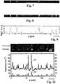
- Figures 9 to 11 illustrate the scattering intensity as a function of position when an aqueous suspension of dielectric latex nanoparticles are conveyed along the channel path.
- the dielectric latex nanoparticles have nominal diameters of 19 nm, 35 nm and 51 nm, each of which respectively corresponds to scattering cross-sections of 0.0023 nm2, 0.09 nm2 and 0.86 nm2 for a wavelength of 670nm.
- Fig. 7 is an exemplary raw image of the latex nanoparticles with an exposure time of 1 ms, while Fig. 8 depicts the same image in logarithmic false colour (here: grey-scale picture).
- Fig. 9 illustrates a semi-logarithmic plot of the sum scattering intensity log I as a function of position "p" (in ⁇ m).
- the particle detection apparatus is capable of detecting the dielectric latex nanoparticles with nominal diameters of 19 nm, 35 nm and 51 nm.
- the particle detection apparatus enables measurement of the scattering intensity and tracking of each particle's motion through detection of the scattered light.
- Such measurement of the scattering intensity of each detected particle and such tracking of each particle's motion not only provides information about each detected particle, but also permits the study of the thermal diffusion and thereby the hydrodynamic behavior of each particle.
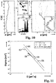
- Fig. 10 illustrates the tracking of the positions "p" (in ⁇ m) of the above dielectric latex nanoparticles and 26 nm single cowpea chlorotic mottle viruses (CCMV) with time t [in sec] using the particle detection apparatus.
- CCMV chlorotic mottle viruses
- Fig. 10 includes a plot of the average detected scattering intensity "I" as a function of the extracted diffusion constants D for the above dielectric latex particles and 26nm single CCMV, and a histogram of the logarithm of the detected scattering intensities for the tracked particles. It can be seen from the plot and histogram of Fig. 10 , as indicated by reference numerals 42,44,46,50,52,54, that the different dielectric latex nanoparticles with different nominal diameters exhibits significantly different scattering intensities from each other. The particle detection is therefore capable of distinguishing between the different dielectric latex nanoparticles with different nominal diameters based on their different scattering cross-sections.
- the particle detection apparatus 30 is capable of distinguishing between the dielectric latex nanoparticles and the single CCMV.
- Each detected particle's diffusion constant and size is obtained by:
- Fig. 11 illustrates a theoretical comparison of scattering cross-section sigma (in [nm 2 ]) versus diffusion constant D (in ⁇ m2/s) for spherical particles of different refractive indices n1 and n2 and for particle aggregates.
- the circular dots 58 in Fig. 11 represent a theoretical model of the scattering cross-section versus diffusion constant of aggregates of multiple 20 nm latex nanoparticles.
- Fig. 12 illustrates the tracking of the positions of single cowpea chlorotic mottle viruses (CCMV) with time using the particle detection apparatus.
- CCMV chlorotic mottle viruses
- the configuration of the monitoring device to detect scattered light permits the use of metallic, semiconductor or organic contrast agents to enhance the polarizability of each particle and thereby enhance the detection sensitivity of the particle detection apparatus.
- the configuration of the monitoring device to detect both scattered and fluorescent light permits simultaneous measurement of the scattering and fluorescence in order to measure an emission spectrum of each particle. This permits identification of each particle on the basis of its spectral features.
- Measurement of the scattering intensity of the scattered light permits the study of particle interaction. For example, measurement of the scattering intensity of the scattered light permits the study of particle binding and unbinding events through detection of quadratic changes in the scattering intensity, the spectral response or the diffusion constant of each particle.
- the monitoring device may be configured to measure the spectrum of the scattered light and/or the distribution of the scattered light over a plurality of directions.
- the thermal diffusion of small particles in a liquid is inversely proportional to its size and can reach tens of square micrometers per second for a 10-nanometer spherical particle in water, thus limiting the available detection period to the duration in which the particle spends in an imaging focal place.
- the configuration of the particle detection apparatus of Fig. 1 allows the particles in the channel path to stay illuminated by the guided light and thereby remain in the imaging plane and not diffuse out of focus. Keeping the particles in the illumination plane of the guide light not only obviates the need for immobilisation of particles in a restricted volume, such as that performed in cryogenic electron microscopy, and thereby results in a less complex and cheaper particle detection apparatus, but also provides a prolonged detection period that permits enhanced real-time tracking of each particle and increases the obtainable amount of information about each particle.
- the improved detection capabilities of the particle detection apparatus as set out above not only obviates the need for a specialised monitoring device to detect each particle and thereby permits use of simpler and cheaper monitoring devices, such as an optical microscope, various kinds of photo-detectors, line CCD detectors or a smartphone camera, but also permits detection of each particle under ambient conditions, instead of specific conditions as required by cryogenic electron microscopy.
- the particle detection apparatus may include a driving mechanism for driving each particle to flow along the channel path.
- a driving mechanism for driving each particle to flow along the channel path.
- electrodes may be incorporated into the channel 4 to permit use of an electrophoretic force to steer each particle along the channel path.
Claims (12)
- Cellule de mesure à utiliser en cytométrie en flux, dotée d'une cavité pour recevoir un échantillon pour essai, caractérisée en ce que la cellule de mesure est configurée sous la forme d'un guide d'ondes optique destiné à guider un faisceau lumineux, ledit guide d'ondes optique (1) comprenant un coeur (3) présentant un indice de réfraction nk, lequel s'étend le long d'un axe longitudinal (9) dudit guide d'ondes (1), présente une aire de section transversale AK inférieure à 80 µm2 dans une section perpendiculaire à l'axe longitudinal (9), et lequel est entouré d'une gaine (2) présentant un indice de réfraction plus petit que nk, dans laquelle ladite cavité forme un canal (4) s'étendant le long de l'axe longitudinal (9), formé à l'intérieur dudit coeur (3), ou en contact avec celui-ci, et présentant au moins une extrémité ouverte avec une zone d'ouverture AH inférieure à 0,2 µm2, et en ce que le coeur (3) et la gaine (2) sont fabriqués dans un matériau massif et solide.
- Cellule de mesure selon la revendication 1, caractérisée en ce que la différence entre les indices de réfraction du coeur (3) et de la gaine (2), l'aire de section du coeur (3), et la longueur d'onde du faisceau lumineux guidé sont coordonnés de telle sorte que le mode fondamental du faisceau lumineux ainsi que pas plus de 20 autres modes peuvent être propagés.
- Cellule de mesure selon la revendication 1 ou 2, caractérisée en ce que le coeur (3) et la gaine (2) sont composés de verre hautement siliceux.
- Cellule de mesure selon la revendication 3, caractérisée en ce que le coeur (3) consiste en du verre de quartz dopé à l'oxyde de germanium, et en ce que la gaine (2) consiste en du verre de quartz, lequel n'est pas dopé ou est dopé avec un composant, notamment du fluor, en mesure de faire diminuer l'indice de réfraction du verre de quartz.
- Cellule de mesure selon la revendication 3, caractérisée en ce que le coeur (3) consiste en du verre de quartz non dopé, et en ce que la gaine (2) consiste en du verre de quartz présentant un indice de réfraction nc, ledit verre de quartz est dopé avec un composant, notamment du fluor, en mesure de faire diminuer l'indice de réfraction du verre de quartz.
- Cellule de mesure selon la revendication 5, caractérisée en ce que la différence nk-nc est au moins égale à 16 x 10-3, et de préférence égale à 20 x 10-3.
- Cellule de mesure selon l'une quelconque des revendications précédentes, caractérisée en ce que dans une section transversale perpendiculaire à l'axe longitudinal, le canal (4) est circulaire, présentant un diamètre dans la plage allant de 20 nm à 500 nm, de préférence dans la plage allant de 50 nm à 300 nm.
- Cellule de mesure selon l'une quelconque des revendications précédentes, caractérisée en ce que dans une section transversale perpendiculaire à l'axe longitudinal, le coeur (3) est circulaire, présentant un diamètre inférieur à 10 µm, de préférence inférieur à 3 µm, et un point central de coeur, lequel est situé à l'intérieur d'une aire de section transversale respective du canal (4).
- Cellule de mesure selon la revendication 8, caractérisée en ce que le canal (4) s'étend entièrement à l'intérieur du coeur (3), et en ce que le rapport AK / AH est supérieur à 4, de préférence supérieur à 20.
- Cellule de mesure selon l'une quelconque des revendications précédentes, caractérisée en ce que le coeur (3), la gaine (2) et le canal (4) s'étendent de manière co-axiale entre eux.
- Cellule de mesure selon l'une quelconque des revendications précédentes, caractérisée en ce que le guide d'ondes optique est configuré sous la forme d'une fibre à saut d'indice (1) présentant le canal (4), le canal (4) présentant une largeur d'ouverture plus petite que la longueur d'onde du faisceau lumineux à guider.
- Cellule de mesure selon l'une quelconque des revendications précédentes, caractérisée en ce que le guide d'ondes optique est configuré sous la forme d'une fibre optique (1) présentant une section circulaire, dans lequel la gaine (2) présente un diamètre extérieur dans la plage allant de 150 µm à 300 µm.
Priority Applications (7)
| Application Number | Priority Date | Filing Date | Title |
|---|---|---|---|
| EP14184150.2A EP2995932B1 (fr) | 2014-09-09 | 2014-09-09 | Fibre optique avec un canal creux le long de l'àme du fibre optique pour recevoir un échantillon d'essai |
| CN201580048424.8A CN106796322B (zh) | 2014-09-09 | 2015-09-08 | 具有沿纤芯中心的中空通道以用于接收样本的光纤 |
| KR1020177009401A KR102122326B1 (ko) | 2014-09-09 | 2015-09-08 | 샘플을 수용하기 위한 섬유 코어의 중심을 따르는 중공 채널을 갖는 광 섬유 |
| PCT/EP2015/070461 WO2016038015A1 (fr) | 2014-09-09 | 2015-09-08 | Fibre optique à canal creux le long du centre du cœur de fibre en vue d'une réception d'échantillon |
| JP2017513490A JP6552606B2 (ja) | 2014-09-09 | 2015-09-08 | ファイバコアの中心に沿って、試料を収容するための中空管路を備えている光ファイバ |
| AU2015314363A AU2015314363B2 (en) | 2014-09-09 | 2015-09-08 | Optical fiber with a hollow channel along the center of the fiber core for receiving a sample |
| US15/509,682 US10281389B2 (en) | 2014-09-09 | 2015-09-08 | Light guiding measuring cell for use in flow cytometry |
Applications Claiming Priority (1)
| Application Number | Priority Date | Filing Date | Title |
|---|---|---|---|
| EP14184150.2A EP2995932B1 (fr) | 2014-09-09 | 2014-09-09 | Fibre optique avec un canal creux le long de l'àme du fibre optique pour recevoir un échantillon d'essai |
Publications (2)
| Publication Number | Publication Date |
|---|---|
| EP2995932A1 EP2995932A1 (fr) | 2016-03-16 |
| EP2995932B1 true EP2995932B1 (fr) | 2019-02-27 |
Family
ID=51518612
Family Applications (1)
| Application Number | Title | Priority Date | Filing Date |
|---|---|---|---|
| EP14184150.2A Active EP2995932B1 (fr) | 2014-09-09 | 2014-09-09 | Fibre optique avec un canal creux le long de l'àme du fibre optique pour recevoir un échantillon d'essai |
Country Status (7)
| Country | Link |
|---|---|
| US (1) | US10281389B2 (fr) |
| EP (1) | EP2995932B1 (fr) |
| JP (1) | JP6552606B2 (fr) |
| KR (1) | KR102122326B1 (fr) |
| CN (1) | CN106796322B (fr) |
| AU (1) | AU2015314363B2 (fr) |
| WO (1) | WO2016038015A1 (fr) |
Families Citing this family (8)
| Publication number | Priority date | Publication date | Assignee | Title |
|---|---|---|---|---|
| JP6890669B2 (ja) * | 2017-02-20 | 2021-06-18 | ザ リージェンツ オブ ザ ユニヴァーシティ オブ カリフォルニアThe Regents of the University of California | 微小毛細血管における生体分子の高効率な光学的検出 |
| WO2018152478A1 (fr) | 2017-02-20 | 2018-08-23 | The Regents Of The University Of California | Sources de lumière pouvant fonctionner physiquement et reconfigurables mécaniquement |
| WO2019121836A1 (fr) * | 2017-12-22 | 2019-06-27 | Imec Vzw | Dispositif d'éclairage d'une particule, et système et procédé d'imagerie de particules |
| EP3599455B1 (fr) * | 2018-07-27 | 2022-03-23 | Heraeus Quarzglas GmbH & Co. KG | Dispositif et procédé d'analyse des particules |
| EP3708998A1 (fr) * | 2019-03-13 | 2020-09-16 | Max-Planck-Gesellschaft zur Förderung der Wissenschaften e.V. | Appareil et procédés de tests de particules |
| WO2020232581A1 (fr) * | 2019-05-17 | 2020-11-26 | Genesense Technology Limited | Système d'analyse pour la détection de molécules |
| EP3766841B1 (fr) * | 2019-07-17 | 2024-02-28 | Heraeus Quarzglas GmbH & Co. KG | Procédé de fabrication d'une fibre à coeur creux et d'une préforme de fibre à coeur creux |
| CN115435924B (zh) * | 2022-11-09 | 2023-02-07 | 中国科学院新疆理化技术研究所 | 基于双孔光纤的温度传感器 |
Family Cites Families (19)
| Publication number | Priority date | Publication date | Assignee | Title |
|---|---|---|---|---|
| GB2199422B (en) * | 1986-11-28 | 1991-04-10 | Fujikura Ltd | Optical fiber coupler having grooved substrate and manufacturing thereof |
| EP0433240A3 (en) * | 1989-12-13 | 1992-08-19 | Centre Suisse D'electronique Et De Microtechnique S.A. | Optical transducer cell of high efficiency with application to optical sensors |
| US6157763A (en) * | 1998-01-28 | 2000-12-05 | Sdl, Inc. | Double-clad optical fiber with improved inner cladding geometry |
| KR20010052659A (ko) * | 1998-06-09 | 2001-06-25 | 크리스탈 화이버 에이/에스 | 광자 밴드갭 섬유 |
| DE60138698D1 (de) * | 2000-03-17 | 2009-06-25 | Corning Inc | Optische wellenleiterlinse und herstellungsverfahren |
| US6542231B1 (en) * | 2000-08-22 | 2003-04-01 | Thermo Finnegan Llc | Fiber-coupled liquid sample analyzer with liquid flow cell |
| FR2870598B1 (fr) * | 2004-05-18 | 2006-07-14 | Total France Sa | Sonde de mesure de la lumiere dans un liquide, sonde de detection du seuil de floculation d'un milieu colloidal, procede de detection associe et application a la determination de la floculation des asphaltenes |
| DE102007025688A1 (de) * | 2007-06-01 | 2008-12-11 | MAX-PLANCK-Gesellschaft zur Förderung der Wissenschaften e.V. | Wellenlängen- oder polarisationssensitiver optischer Aufbau und dessen Verwendung |
| JP5055646B2 (ja) * | 2008-06-02 | 2012-10-24 | セイコーインスツル株式会社 | 情報記録再生装置 |
| US8270786B2 (en) * | 2008-11-21 | 2012-09-18 | Ofs Fitel, Llc | Optical fiber mode couplers |
| JP5308834B2 (ja) | 2009-01-13 | 2013-10-09 | 古河電気工業株式会社 | 微粒子分別装置及び微粒子分別方法 |
| JP5467826B2 (ja) * | 2009-09-16 | 2014-04-09 | 日東電工株式会社 | 光電気混載モジュールおよびその製造方法 |
| WO2011037533A1 (fr) | 2009-09-25 | 2011-03-31 | Nanexa Ab | Dispositif sers |
| WO2011066071A1 (fr) * | 2009-11-30 | 2011-06-03 | Corning Incorporated | Procédé de mesure de longueur d'onde de résonance pour lecteur optique à balayage indépendant du marqueur |
| KR101302412B1 (ko) * | 2012-08-01 | 2013-09-02 | 광주과학기술원 | 화학 센서용 광섬유 |
| CN103063645B (zh) * | 2013-01-04 | 2017-12-05 | 南开大学 | 基于新型微结构光纤的高效荧光检测 |
| DE102013210259B4 (de) | 2013-06-03 | 2022-06-23 | Postnova Analytics Gmbh | Verfahren zur Messung von Streulicht und Vorrichtung zur Messung von Streulicht |
| GB2530034B (en) * | 2014-09-09 | 2017-08-09 | Max-Planck-Gesellschaft Zur Forderung Der Wss E V | Particle detection apparatus |
| JP6692128B2 (ja) * | 2015-07-02 | 2020-05-13 | 株式会社フジクラ | マルチコア偏波保持ファイバ |
-
2014
- 2014-09-09 EP EP14184150.2A patent/EP2995932B1/fr active Active
-
2015
- 2015-09-08 US US15/509,682 patent/US10281389B2/en active Active
- 2015-09-08 JP JP2017513490A patent/JP6552606B2/ja active Active
- 2015-09-08 CN CN201580048424.8A patent/CN106796322B/zh active Active
- 2015-09-08 WO PCT/EP2015/070461 patent/WO2016038015A1/fr active Application Filing
- 2015-09-08 KR KR1020177009401A patent/KR102122326B1/ko active IP Right Grant
- 2015-09-08 AU AU2015314363A patent/AU2015314363B2/en active Active
Non-Patent Citations (1)
| Title |
|---|
| G. S. WIEDERHECKER ET AL: "Field enhancement within an optical fibre with a subwavelength air core", NATURE PHOTONICS, vol. 1, no. 2, 1 February 2007 (2007-02-01), pages 115 - 118, XP055183874, ISSN: 1749-4885, DOI: 10.1038/nphoton.2006.81 * |
Also Published As
| Publication number | Publication date |
|---|---|
| KR102122326B1 (ko) | 2020-06-15 |
| CN106796322A (zh) | 2017-05-31 |
| JP2017532545A (ja) | 2017-11-02 |
| KR20170055979A (ko) | 2017-05-22 |
| WO2016038015A1 (fr) | 2016-03-17 |
| US20170261423A1 (en) | 2017-09-14 |
| AU2015314363A1 (en) | 2017-04-06 |
| JP6552606B2 (ja) | 2019-07-31 |
| AU2015314363B2 (en) | 2018-11-01 |
| EP2995932A1 (fr) | 2016-03-16 |
| US10281389B2 (en) | 2019-05-07 |
| CN106796322B (zh) | 2020-06-05 |
Similar Documents
| Publication | Publication Date | Title |
|---|---|---|
| US10281389B2 (en) | Light guiding measuring cell for use in flow cytometry | |
| EP3191814B1 (fr) | Appareil de détection de particules | |
| Calcerrada et al. | Chemical and biochemical sensing applications of microstructured optical fiber‐based systems | |
| US8928875B2 (en) | Methods and systems for optical characterisation | |
| US10852231B2 (en) | Method and device for near-infrared spectroscopy | |
| CN103398974B (zh) | 一种光纤传感器、制备方法及测量系统 | |
| Jiang et al. | Three dimensional spatiotemporal nano-scale position retrieval of the confined diffusion of nano-objects inside optofluidic microstructured fibers | |
| Jiang et al. | Three-dimensional spatiotemporal tracking of nano-objects diffusing in water-filled optofluidic microstructured fiber | |
| JP6882386B2 (ja) | 粒子を分析するための装置および方法 | |
| Paul et al. | Influence of probe geometry of optical fibers in sensing volatile liquids through localized surface plasmon resonance | |
| US20220187532A1 (en) | Optical fiber for sensing an analyte, methods of forming and using the same | |
| Borecki et al. | Light transmission characteristics of silica capillaries | |
| Sun et al. | Long path-length axial absorption detection in photonic crystal fiber | |
| Malinin et al. | Biological sensor based on a hollow-core photonic crystal fiber | |
| Shinoj et al. | An HC-PCF Fluorescence Spectrocopy for Detection of Microsphere Samples Based on Refractive Index Scaling Law | |
| Troles et al. | Exposed-core chalcogenide microstructured optical fibers for chemical sensing | |
| Matějec et al. | Bragg fibers for absorption-based sensing | |
| Schmidt | Optofluidic microstructured fibers: a nanoparticle tracking analysis platform for understanding nanoscale objects such as SARS-CoV-2 | |
| Esposito et al. | Long Period Grating based Biosensing Technology for the Detection of Vitamin D3. | |
| CN117074311A (zh) | 液体浓度检测用微泡透镜传感芯片及制备方法和检测系统 | |
| Matjjec et al. | Conference Paper Bragg Fibers for Absorption-Based Sensing |
Legal Events
| Date | Code | Title | Description |
|---|---|---|---|
| PUAI | Public reference made under article 153(3) epc to a published international application that has entered the european phase |
Free format text: ORIGINAL CODE: 0009012 |
|
| AK | Designated contracting states |
Kind code of ref document: A1 Designated state(s): AL AT BE BG CH CY CZ DE DK EE ES FI FR GB GR HR HU IE IS IT LI LT LU LV MC MK MT NL NO PL PT RO RS SE SI SK SM TR |
|
| AX | Request for extension of the european patent |
Extension state: BA ME |
|
| 17P | Request for examination filed |
Effective date: 20160914 |
|
| RBV | Designated contracting states (corrected) |
Designated state(s): AL AT BE BG CH CY CZ DE DK EE ES FI FR GB GR HR HU IE IS IT LI LT LU LV MC MK MT NL NO PL PT RO RS SE SI SK SM TR |
|
| STAA | Information on the status of an ep patent application or granted ep patent |
Free format text: STATUS: EXAMINATION IS IN PROGRESS |
|
| 17Q | First examination report despatched |
Effective date: 20170925 |
|
| GRAP | Despatch of communication of intention to grant a patent |
Free format text: ORIGINAL CODE: EPIDOSNIGR1 |
|
| STAA | Information on the status of an ep patent application or granted ep patent |
Free format text: STATUS: GRANT OF PATENT IS INTENDED |
|
| INTG | Intention to grant announced |
Effective date: 20180919 |
|
| GRAS | Grant fee paid |
Free format text: ORIGINAL CODE: EPIDOSNIGR3 |
|
| GRAA | (expected) grant |
Free format text: ORIGINAL CODE: 0009210 |
|
| STAA | Information on the status of an ep patent application or granted ep patent |
Free format text: STATUS: THE PATENT HAS BEEN GRANTED |
|
| AK | Designated contracting states |
Kind code of ref document: B1 Designated state(s): AL AT BE BG CH CY CZ DE DK EE ES FI FR GB GR HR HU IE IS IT LI LT LU LV MC MK MT NL NO PL PT RO RS SE SI SK SM TR |
|
| REG | Reference to a national code |
Ref country code: GB Ref legal event code: FG4D |
|
| REG | Reference to a national code |
Ref country code: CH Ref legal event code: EP |
|
| REG | Reference to a national code |
Ref country code: AT Ref legal event code: REF Ref document number: 1102081 Country of ref document: AT Kind code of ref document: T Effective date: 20190315 |
|
| REG | Reference to a national code |
Ref country code: IE Ref legal event code: FG4D |
|
| REG | Reference to a national code |
Ref country code: DE Ref legal event code: R096 Ref document number: 602014041697 Country of ref document: DE |
|
| REG | Reference to a national code |
Ref country code: NL Ref legal event code: MP Effective date: 20190227 |
|
| REG | Reference to a national code |
Ref country code: LT Ref legal event code: MG4D |
|
| PG25 | Lapsed in a contracting state [announced via postgrant information from national office to epo] |
Ref country code: SE Free format text: LAPSE BECAUSE OF FAILURE TO SUBMIT A TRANSLATION OF THE DESCRIPTION OR TO PAY THE FEE WITHIN THE PRESCRIBED TIME-LIMIT Effective date: 20190227 Ref country code: LT Free format text: LAPSE BECAUSE OF FAILURE TO SUBMIT A TRANSLATION OF THE DESCRIPTION OR TO PAY THE FEE WITHIN THE PRESCRIBED TIME-LIMIT Effective date: 20190227 Ref country code: NL Free format text: LAPSE BECAUSE OF FAILURE TO SUBMIT A TRANSLATION OF THE DESCRIPTION OR TO PAY THE FEE WITHIN THE PRESCRIBED TIME-LIMIT Effective date: 20190227 Ref country code: PT Free format text: LAPSE BECAUSE OF FAILURE TO SUBMIT A TRANSLATION OF THE DESCRIPTION OR TO PAY THE FEE WITHIN THE PRESCRIBED TIME-LIMIT Effective date: 20190627 Ref country code: FI Free format text: LAPSE BECAUSE OF FAILURE TO SUBMIT A TRANSLATION OF THE DESCRIPTION OR TO PAY THE FEE WITHIN THE PRESCRIBED TIME-LIMIT Effective date: 20190227 Ref country code: NO Free format text: LAPSE BECAUSE OF FAILURE TO SUBMIT A TRANSLATION OF THE DESCRIPTION OR TO PAY THE FEE WITHIN THE PRESCRIBED TIME-LIMIT Effective date: 20190527 |
|
| PG25 | Lapsed in a contracting state [announced via postgrant information from national office to epo] |
Ref country code: IS Free format text: LAPSE BECAUSE OF FAILURE TO SUBMIT A TRANSLATION OF THE DESCRIPTION OR TO PAY THE FEE WITHIN THE PRESCRIBED TIME-LIMIT Effective date: 20190627 Ref country code: BG Free format text: LAPSE BECAUSE OF FAILURE TO SUBMIT A TRANSLATION OF THE DESCRIPTION OR TO PAY THE FEE WITHIN THE PRESCRIBED TIME-LIMIT Effective date: 20190527 Ref country code: HR Free format text: LAPSE BECAUSE OF FAILURE TO SUBMIT A TRANSLATION OF THE DESCRIPTION OR TO PAY THE FEE WITHIN THE PRESCRIBED TIME-LIMIT Effective date: 20190227 Ref country code: RS Free format text: LAPSE BECAUSE OF FAILURE TO SUBMIT A TRANSLATION OF THE DESCRIPTION OR TO PAY THE FEE WITHIN THE PRESCRIBED TIME-LIMIT Effective date: 20190227 Ref country code: GR Free format text: LAPSE BECAUSE OF FAILURE TO SUBMIT A TRANSLATION OF THE DESCRIPTION OR TO PAY THE FEE WITHIN THE PRESCRIBED TIME-LIMIT Effective date: 20190528 |
|
| REG | Reference to a national code |
Ref country code: AT Ref legal event code: MK05 Ref document number: 1102081 Country of ref document: AT Kind code of ref document: T Effective date: 20190227 |
|
| PG25 | Lapsed in a contracting state [announced via postgrant information from national office to epo] |
Ref country code: ES Free format text: LAPSE BECAUSE OF FAILURE TO SUBMIT A TRANSLATION OF THE DESCRIPTION OR TO PAY THE FEE WITHIN THE PRESCRIBED TIME-LIMIT Effective date: 20190227 Ref country code: AL Free format text: LAPSE BECAUSE OF FAILURE TO SUBMIT A TRANSLATION OF THE DESCRIPTION OR TO PAY THE FEE WITHIN THE PRESCRIBED TIME-LIMIT Effective date: 20190227 Ref country code: CZ Free format text: LAPSE BECAUSE OF FAILURE TO SUBMIT A TRANSLATION OF THE DESCRIPTION OR TO PAY THE FEE WITHIN THE PRESCRIBED TIME-LIMIT Effective date: 20190227 Ref country code: SK Free format text: LAPSE BECAUSE OF FAILURE TO SUBMIT A TRANSLATION OF THE DESCRIPTION OR TO PAY THE FEE WITHIN THE PRESCRIBED TIME-LIMIT Effective date: 20190227 Ref country code: RO Free format text: LAPSE BECAUSE OF FAILURE TO SUBMIT A TRANSLATION OF THE DESCRIPTION OR TO PAY THE FEE WITHIN THE PRESCRIBED TIME-LIMIT Effective date: 20190227 Ref country code: IT Free format text: LAPSE BECAUSE OF FAILURE TO SUBMIT A TRANSLATION OF THE DESCRIPTION OR TO PAY THE FEE WITHIN THE PRESCRIBED TIME-LIMIT Effective date: 20190227 Ref country code: DK Free format text: LAPSE BECAUSE OF FAILURE TO SUBMIT A TRANSLATION OF THE DESCRIPTION OR TO PAY THE FEE WITHIN THE PRESCRIBED TIME-LIMIT Effective date: 20190227 Ref country code: EE Free format text: LAPSE BECAUSE OF FAILURE TO SUBMIT A TRANSLATION OF THE DESCRIPTION OR TO PAY THE FEE WITHIN THE PRESCRIBED TIME-LIMIT Effective date: 20190227 |
|
| REG | Reference to a national code |
Ref country code: DE Ref legal event code: R082 Ref document number: 602014041697 Country of ref document: DE Representative=s name: BRAND, NORMEN, DR. RER. NAT., DE Ref country code: DE Ref legal event code: R082 Ref document number: 602014041697 Country of ref document: DE Representative=s name: BRAND, NORMEN, DIPL.-CHEM. UNIV. DR. RER. NAT., DE |
|
| REG | Reference to a national code |
Ref country code: DE Ref legal event code: R097 Ref document number: 602014041697 Country of ref document: DE |
|
| PG25 | Lapsed in a contracting state [announced via postgrant information from national office to epo] |
Ref country code: PL Free format text: LAPSE BECAUSE OF FAILURE TO SUBMIT A TRANSLATION OF THE DESCRIPTION OR TO PAY THE FEE WITHIN THE PRESCRIBED TIME-LIMIT Effective date: 20190227 Ref country code: SM Free format text: LAPSE BECAUSE OF FAILURE TO SUBMIT A TRANSLATION OF THE DESCRIPTION OR TO PAY THE FEE WITHIN THE PRESCRIBED TIME-LIMIT Effective date: 20190227 |
|
| PG25 | Lapsed in a contracting state [announced via postgrant information from national office to epo] |
Ref country code: AT Free format text: LAPSE BECAUSE OF FAILURE TO SUBMIT A TRANSLATION OF THE DESCRIPTION OR TO PAY THE FEE WITHIN THE PRESCRIBED TIME-LIMIT Effective date: 20190227 |
|
| PLBE | No opposition filed within time limit |
Free format text: ORIGINAL CODE: 0009261 |
|
| STAA | Information on the status of an ep patent application or granted ep patent |
Free format text: STATUS: NO OPPOSITION FILED WITHIN TIME LIMIT |
|
| 26N | No opposition filed |
Effective date: 20191128 |
|
| PG25 | Lapsed in a contracting state [announced via postgrant information from national office to epo] |
Ref country code: SI Free format text: LAPSE BECAUSE OF FAILURE TO SUBMIT A TRANSLATION OF THE DESCRIPTION OR TO PAY THE FEE WITHIN THE PRESCRIBED TIME-LIMIT Effective date: 20190227 |
|
| PG25 | Lapsed in a contracting state [announced via postgrant information from national office to epo] |
Ref country code: TR Free format text: LAPSE BECAUSE OF FAILURE TO SUBMIT A TRANSLATION OF THE DESCRIPTION OR TO PAY THE FEE WITHIN THE PRESCRIBED TIME-LIMIT Effective date: 20190227 |
|
| PG25 | Lapsed in a contracting state [announced via postgrant information from national office to epo] |
Ref country code: MC Free format text: LAPSE BECAUSE OF FAILURE TO SUBMIT A TRANSLATION OF THE DESCRIPTION OR TO PAY THE FEE WITHIN THE PRESCRIBED TIME-LIMIT Effective date: 20190227 |
|
| REG | Reference to a national code |
Ref country code: CH Ref legal event code: PL |
|
| PG25 | Lapsed in a contracting state [announced via postgrant information from national office to epo] |
Ref country code: CH Free format text: LAPSE BECAUSE OF NON-PAYMENT OF DUE FEES Effective date: 20190930 Ref country code: LI Free format text: LAPSE BECAUSE OF NON-PAYMENT OF DUE FEES Effective date: 20190930 Ref country code: IE Free format text: LAPSE BECAUSE OF NON-PAYMENT OF DUE FEES Effective date: 20190909 Ref country code: LU Free format text: LAPSE BECAUSE OF NON-PAYMENT OF DUE FEES Effective date: 20190909 |
|
| REG | Reference to a national code |
Ref country code: BE Ref legal event code: MM Effective date: 20190930 |
|
| PG25 | Lapsed in a contracting state [announced via postgrant information from national office to epo] |
Ref country code: BE Free format text: LAPSE BECAUSE OF NON-PAYMENT OF DUE FEES Effective date: 20190930 |
|
| PG25 | Lapsed in a contracting state [announced via postgrant information from national office to epo] |
Ref country code: CY Free format text: LAPSE BECAUSE OF FAILURE TO SUBMIT A TRANSLATION OF THE DESCRIPTION OR TO PAY THE FEE WITHIN THE PRESCRIBED TIME-LIMIT Effective date: 20190227 |
|
| PG25 | Lapsed in a contracting state [announced via postgrant information from national office to epo] |
Ref country code: MT Free format text: LAPSE BECAUSE OF FAILURE TO SUBMIT A TRANSLATION OF THE DESCRIPTION OR TO PAY THE FEE WITHIN THE PRESCRIBED TIME-LIMIT Effective date: 20190227 Ref country code: HU Free format text: LAPSE BECAUSE OF FAILURE TO SUBMIT A TRANSLATION OF THE DESCRIPTION OR TO PAY THE FEE WITHIN THE PRESCRIBED TIME-LIMIT; INVALID AB INITIO Effective date: 20140909 |
|
| PG25 | Lapsed in a contracting state [announced via postgrant information from national office to epo] |
Ref country code: MK Free format text: LAPSE BECAUSE OF FAILURE TO SUBMIT A TRANSLATION OF THE DESCRIPTION OR TO PAY THE FEE WITHIN THE PRESCRIBED TIME-LIMIT Effective date: 20190227 |
|
| PGFP | Annual fee paid to national office [announced via postgrant information from national office to epo] |
Ref country code: GB Payment date: 20230920 Year of fee payment: 10 |
|
| PGFP | Annual fee paid to national office [announced via postgrant information from national office to epo] |
Ref country code: FR Payment date: 20230928 Year of fee payment: 10 Ref country code: DE Payment date: 20230920 Year of fee payment: 10 |
|
| PGFP | Annual fee paid to national office [announced via postgrant information from national office to epo] |
Ref country code: LV Payment date: 20230918 Year of fee payment: 10 |