EP2995356A2 - Adjusting group - Google Patents
Adjusting group Download PDFInfo
- Publication number
- EP2995356A2 EP2995356A2 EP15184413.1A EP15184413A EP2995356A2 EP 2995356 A2 EP2995356 A2 EP 2995356A2 EP 15184413 A EP15184413 A EP 15184413A EP 2995356 A2 EP2995356 A2 EP 2995356A2
- Authority
- EP
- European Patent Office
- Prior art keywords
- user
- interface
- slide
- guide
- frame
- Prior art date
- Legal status (The legal status is an assumption and is not a legal conclusion. Google has not performed a legal analysis and makes no representation as to the accuracy of the status listed.)
- Granted
Links
- 230000000903 blocking effect Effects 0.000 claims abstract description 37
- 230000008878 coupling Effects 0.000 claims abstract description 29
- 238000010168 coupling process Methods 0.000 claims abstract description 29
- 238000005859 coupling reaction Methods 0.000 claims abstract description 29
- 238000006073 displacement reaction Methods 0.000 claims description 3
- 238000000034 method Methods 0.000 claims 3
- 238000009987 spinning Methods 0.000 description 7
- 230000036544 posture Effects 0.000 description 5
- 230000000670 limiting effect Effects 0.000 description 4
- 230000000386 athletic effect Effects 0.000 description 2
- 230000001351 cycling effect Effects 0.000 description 2
- 230000001681 protective effect Effects 0.000 description 2
- 230000000284 resting effect Effects 0.000 description 2
- 241000755266 Kathetostoma giganteum Species 0.000 description 1
- XAGFODPZIPBFFR-UHFFFAOYSA-N aluminium Chemical compound [Al] XAGFODPZIPBFFR-UHFFFAOYSA-N 0.000 description 1
- 229910052782 aluminium Inorganic materials 0.000 description 1
- 239000004411 aluminium Substances 0.000 description 1
- 230000002452 interceptive effect Effects 0.000 description 1
- 239000000463 material Substances 0.000 description 1
- 239000011159 matrix material Substances 0.000 description 1
- 230000001394 metastastic effect Effects 0.000 description 1
- 206010061289 metastatic neoplasm Diseases 0.000 description 1
- 238000012986 modification Methods 0.000 description 1
- 230000004048 modification Effects 0.000 description 1
- 210000003205 muscle Anatomy 0.000 description 1
- 230000002829 reductive effect Effects 0.000 description 1
Images


Classifications
-
- F—MECHANICAL ENGINEERING; LIGHTING; HEATING; WEAPONS; BLASTING
- F16—ENGINEERING ELEMENTS AND UNITS; GENERAL MEASURES FOR PRODUCING AND MAINTAINING EFFECTIVE FUNCTIONING OF MACHINES OR INSTALLATIONS; THERMAL INSULATION IN GENERAL
- F16M—FRAMES, CASINGS OR BEDS OF ENGINES, MACHINES OR APPARATUS, NOT SPECIFIC TO ENGINES, MACHINES OR APPARATUS PROVIDED FOR ELSEWHERE; STANDS; SUPPORTS
- F16M13/00—Other supports for positioning apparatus or articles; Means for steadying hand-held apparatus or articles
- F16M13/02—Other supports for positioning apparatus or articles; Means for steadying hand-held apparatus or articles for supporting on, or attaching to, an object, e.g. tree, gate, window-frame, cycle
-
- A—HUMAN NECESSITIES
- A63—SPORTS; GAMES; AMUSEMENTS
- A63B—APPARATUS FOR PHYSICAL TRAINING, GYMNASTICS, SWIMMING, CLIMBING, OR FENCING; BALL GAMES; TRAINING EQUIPMENT
- A63B22/00—Exercising apparatus specially adapted for conditioning the cardio-vascular system, for training agility or co-ordination of movements
- A63B22/0046—Details of the support elements or their connection to the exercising apparatus, e.g. adjustment of size or orientation
-
- A—HUMAN NECESSITIES
- A63—SPORTS; GAMES; AMUSEMENTS
- A63B—APPARATUS FOR PHYSICAL TRAINING, GYMNASTICS, SWIMMING, CLIMBING, OR FENCING; BALL GAMES; TRAINING EQUIPMENT
- A63B22/00—Exercising apparatus specially adapted for conditioning the cardio-vascular system, for training agility or co-ordination of movements
- A63B22/06—Exercising apparatus specially adapted for conditioning the cardio-vascular system, for training agility or co-ordination of movements with support elements performing a rotating cycling movement, i.e. a closed path movement
- A63B22/0605—Exercising apparatus specially adapted for conditioning the cardio-vascular system, for training agility or co-ordination of movements with support elements performing a rotating cycling movement, i.e. a closed path movement performing a circular movement, e.g. ergometers
-
- A—HUMAN NECESSITIES
- A63—SPORTS; GAMES; AMUSEMENTS
- A63B—APPARATUS FOR PHYSICAL TRAINING, GYMNASTICS, SWIMMING, CLIMBING, OR FENCING; BALL GAMES; TRAINING EQUIPMENT
- A63B2225/00—Miscellaneous features of sport apparatus, devices or equipment
- A63B2225/09—Adjustable dimensions
-
- A—HUMAN NECESSITIES
- A63—SPORTS; GAMES; AMUSEMENTS
- A63B—APPARATUS FOR PHYSICAL TRAINING, GYMNASTICS, SWIMMING, CLIMBING, OR FENCING; BALL GAMES; TRAINING EQUIPMENT
- A63B2225/00—Miscellaneous features of sport apparatus, devices or equipment
- A63B2225/09—Adjustable dimensions
- A63B2225/093—Height
-
- F—MECHANICAL ENGINEERING; LIGHTING; HEATING; WEAPONS; BLASTING
- F16—ENGINEERING ELEMENTS AND UNITS; GENERAL MEASURES FOR PRODUCING AND MAINTAINING EFFECTIVE FUNCTIONING OF MACHINES OR INSTALLATIONS; THERMAL INSULATION IN GENERAL
- F16M—FRAMES, CASINGS OR BEDS OF ENGINES, MACHINES OR APPARATUS, NOT SPECIFIC TO ENGINES, MACHINES OR APPARATUS PROVIDED FOR ELSEWHERE; STANDS; SUPPORTS
- F16M2200/00—Details of stands or supports
- F16M2200/02—Locking means
- F16M2200/025—Locking means for translational movement
Definitions
- the present invention relates to an adjusting group.
- the present invention relates to an adjusting group that can be used to optimize the position of a user-interface of a gymnastic machine relative to a respective frame thereof.
- the present invention relates to an adjusting group that can be used to optimize the position of a user-interface of a gymnastic machine relative to a respective frame thereof according to the different modes of use of the machine.
- user-interfaces are usually associated with the frame of these machines, whose purpose is to give the users a rest or support at given parts of the frame, in a completely safe and comfortable way. These user-interfaces are usually seats or rests for feet or hands.
- these interfaces are usually constituted by a saddle and a handlebar, with which a height adjusting device is usually associated.
- the users can adapt the interface positions so as to reproduce the operating conditions under which they race.
- the two cranks allow to tighten the respective guides and slides through a circular movement by a multiple of 360°, for performing which the user shall be at the side, or at the back, of the bike for the necessary time, to prevent earphones cable from becoming entangled and clothes, worn or tied around the waist, from being caught up around the screw.
- the first adjustment is not optimal, the user should repeatedly stop the training session to change it.
- the user can identified the correct position of the interfaces relative to the frame only when he/she is on board and is pedalling; therefore, if the user identified an undesired position, he/she shall interrupt the training session to find the correct position, and this again and again, until he/she finds the optimal adjustment, maybe after a lot of attempts.
- cranks for adjusting the saddle and handlebar position are usually arranged in fixed position with respect to the frame, i.e. at always different distances from the interface whose position, relative to the frame, the user wants to adjust.
- a a spinning training session is comprised of steps, wherein the user pedals with or without resting the hands on the handlebar, and steps where the arms and the back are in particular positions; taking into account that in these bikes the gear is not free with the flywheel acting as rear wheel, and therefore the pedals movement shall be continuous and cannot be interrupted at will (for instance to rest with the feet on the pedals, or to change the bike settings without losing the balance), it is easily to understand that the devices for adjusting the position of the saddle and the handlebar do not meet the needs of the more athletic users in the spinning classes.
- the present invention relates to an adjusting group.
- the present invention relates to an adjusting group that can be used to optimize the position of a user-interface of a gymnastic machine relative to a respective frame thereof.
- the present invention relates to an adjusting group that can be used to customize the position of a user-interface of a gymnastic machine relative to a respective frame thereof according to the different modes of use of the machine.
- An object of the present invention is to provide an adjusting group to regulate the position of a user-interface of a gymnastic machine relative to a respective frame thereof. According to the present invention an adjusting group is provided, whose main features will be described in at least one of the appended claims.
- a further object of the present invention is to provide a bike equipped with said adjusting group to regulate the position of a user-interface of a gymnastic machine relative to a respective frame thereof.
- a bike is provided, equipped with said adjusting group, whose main features will be described in at least one of the appended claims.
- number 100 indicates a gymnastic machine provided with a frame 102 supporting a pair of user-interfaces 2 that can be used by a user to take position on the machine, adopting an adequate posture to perform a customized training session.
- An adjusting group 1 is associated with each user-interface 2, designed to adjust the longitudinal and vertical position of the corresponding user-interface 2 relative to the frame.
- Each adjusting group 1 comprises a sliding coupling unit 120, defining a substantially rectilinear first path L for adjusting the position of the respective user-interface 2 with respect to the frame 102.
- a first blocking device 130 is provided in combination with the coupling unit 120 to fix the corresponding user-interface 2 in any position along the first path (L).
- the coupling unit 120 comprises a guide 122 associated with the frame 102 and a slide 124 associated with the user-interface 2 and coupled to the guide 122 in sliding fashion along respective first coupling surface 1220 of the guide 122 and second coupling surface 1240 of the slide 124.
- Each first blocking device 130 is carried by the respective slide 124 to facilitate the adjustment of the position of the corresponding user-interface 2.
- the guide 122 and the slide 124 may be built using portions of extruded bars of substantially conjugated shape, made of rigid resistant materials of limited density, such as aluminium or the like.
- the gymnastic machine 100 with which at least one adjusting group 1 has been associated, is a stationary bike, of the type used for spinning or for performing exercises in training groups or classes, that will be indicated below with the same number 100, without however limiting the general scope of the invention.
- the bike 100 comprises two user-interfaces 2, in particular a saddle 22 and a handlebar 20; a respective adjusting group 1 is associated with each user-interface.
- the first blocking device 130 associated with the saddle 22 is arranged behind the saddle 22 according to the direction L, i.e. it is arranged, in use, behind the user, while the first blocking device 130 associated with the handlebar 20 is aligned with the direction L from the user's side, i.e.
- the first blocking device 130 comprises a pin 136 arranged transversally to the first path L through the slide 124.
- the pin 136 has a body 1360 engaging a longitudinal groove 1222 ( figure 5 ) provided in substantially central position in the guide 122; this body 1360 is delimited, at the side of the slide 124, by a threaded portion 1362, and engages the guide 122 with a respective end portion 132, shaped like a square plate.
- this plate 132 is a blocking member 132 that may be rigidly fastened to the body 1360 (of the pin 136) or may be freely coupled to the body 1360.
- the body 1360 is shaped like a known flat-head screw; it is therefore provided with a head of greater dimension than that of the body 1360, whose aim is only to act as lower abutment suitable to axially hold a plate externally shaped like the plate 132 but equipped with a central hole allowing it to be axially coupled to the body 1360 of the pin 136 and to take an axially defined position, into tangential contact with the inner face of the screw head.
- each first blocking device 130 furthermore comprises an actuating device provided with a pair with inclined plane, the actuating device and the pair being indicated, for the sake of practicality, with the same reference number 138.
- This pair 138 is provided with a first body 1380 and with a second body 1382, that extend peripherally around the respective pin 136.
- the first body 1380 is rigidly coupled to a handle 134 and has a hole 1340 engaged by the body 1360; the handle 134 has a cavity 1342 housing a nut 1344, with which the threaded portion 1362 is screwed.
- This cavity 1342 is closed by means of a lid 135, held in position by a screw member, shown in the drawing without reference number for the sake of drawing economy.
- the second body 1382 is rigidly connected to the slide 124.
- the connection between the second body 1382 and the slide 124 is provided by means of a mechanical coupling 1383, i.e. a shape coupling between the second body 1382 and the slide 124, without however limiting the scope of the invention.
- the first and the second bodies 1380 and 1382 face each other through respective first surface 1380S with inclined plane and second surface 1382S with inclined plane.
- This first surface 1380S and this second surface 1382S are shaped in a substantially conjugated fashion and are toothed, i.e. they have projections (or teeth) 1380A and 1382A, in equal number, extending vertically in figure 4 .
- each tooth 1382A extends from a substantially horizontal plane S21 having an inclined portion S22 followed by a substantially horizontal flat portion S23 and by an angular abutment B21.
- the handle 134 has been illustrated vertical in figure 7 , even if, in use, it is usually in substantially horizontal position, each tooth 1380A is shaped similarly to each tooth 1382A, but without the angular abutment provided in the corresponding tooth thereof, to avoid undesired interferences.
- the respective inclined portion S02 extends from an upper level than that of a respective plane S01, homologous to the plane S21, and ends in a flat portion S03.
- first teeth 1380A and the second teeth 1382A have increasing thickness according to given angles oriented in the same manner.
- the particular conformation and number of the teeth 1380A and 1382A associate a vertical displacement of the first body 1380 relative to the second body 1382 with a relative angular rotation of the first and second bodies 1380 and 1382.
- to an angular displacement (clockwise or counter-clockwise) of the first body 1380 corresponds a vertical movement of the first body 1380, and therefore of the slide 124, towards or away from the guide 122. Therefore, the particular conformation of the teeth 1380A and 1382A (of the first and second surfaces 1380S and 1382S) influences the entity of the coupling pressure of the slide 124 with respect to the guide 122.
- the vertical position of the pin 136 depends on the vertical position of the first body 1380 with respect to the second body 1382.
- the vertical position of the pin 136 is determined by the angular position of the first body 1380 with respect to the second body 1382, and thus by the angular position of the handle 134, and on this position depends the condition of coupling or free sliding of the slide 124 with respect to the guide 122.
- the clockwise rotation of the handle 134 causes the rotation of the first body 1380 on the second body 1382 and allows axially to switch the pin 136 (and therefore the plate 132) between a first stop operating position P1, wherein it keeps the first coupling surface 1220 and the second coupling surface 1240 into matching contact with each other and keeps the slide 124 firmly connected to the guide 122 and fixed relative to the frame 102 (position of the plate 132 shown in figure 6a ), and a second releasing operating position P2, wherein it frees the first coupling surface 1220 and the second coupling surface 1240 from each other and makes the slide 124 free to slide relative to the guide 122, to find the correct adjusting position for the user-interface 2 relative to the frame 102 according to the user's current needs (position of the plate 132 shown in figure 6b ).
- the counter-clockwise rotation of the handle 134 causes the first body 1380 to raise with respect to the second body 1382 and the pin 136 to be positioned again
- the actuating handle 134 centred on the pin 136, is therefore suitable to switch the plate 132 between the first operating position P1 and the second operating position P2 by means of rotations on a circle arc whose width is, with reference to figure 7 but without limiting the scope of the invention, lower than or equal to 90° in a given direction. Therefore, the direction of rotation to bring the pair 138 with inclined pair in the configuration of figure 6a or in the configuration of figure 6b is univocally identified. In this way, the reciprocal fastening of the slide 124 to the guide 122 is always determined, as well as the releasing thereof.
- the slide 124 carries the user-interface 2 and the actuating handle 134 adjacent to each other so that the handle 134 can be accessed from the top always at the same distance from the user-interface 2 with which it is associated.
- This allows the training user to act on the first blocking device 130 with only one hand, making always the same gesture with reference to a same adjusting member, and therefore to have always at least one hand resting on the handlebar 20.
- the particular conformation of the first blocking device 130 allows the user to find the handle 134 always in the same given position behind the saddle 22 or behind the handlebar 20, independently of the position taken by these user-interfaces relative to the frame 102. It is easily understood that this feature allow to balance the user's posture during all the training steps, even if interspersed with steps where the positions of the user-interfaces 2 are changed so as to allow to take different postures, more suitable to the exercise to be performed.
- the scope of the present invention also comprises the case, not shown, wherein the second body 1382 is carried angularly movable with respect to the slide 124 through the handle 134, while the first body 1380 is held angularly fixed.
- the frame 102 comprises a sleeve 104 extending according to a first given direction D, substantially transversal to the path L, and housing, in an axially sliding fashion, an elongated member 106 delimited at the top by the guide 122.
- a second blocking device 140 is arranged between the elongated member 106 and the sleeve 104 to hold the guide 122 in a given position relative to the frame 102.
- the second blocking device 140 comprises a toothed rack 142, carried by the sleeve 104 in a rigid way, a toothed member 144, carried by the elongated member 106 in a tilting way, and a switching device 150 to switch the position of the toothed member 144 from an engaging position, wherein the toothed member 144 stably engages any space of the toothed rack 142, and a non-engaging position, wherein the toothed member 144 is arranged completely outside the spaces of the toothed rack 142.
- the toothed rack 142 has respective spaces shaped like right-angled triangles, with the smaller leg facing the user-interface 2.
- the second blocking device 140 comprises an elastic return member 146 connected to the toothed member 144 to return the toothed member 144 from the non-engaging position to the engaging position of any of the spaces of the toothed rack 142, to allow the automatic engaging thereof.
- the switching device 150 comprises a handle 148 carried by the elongated member 106 at the side of the guide 122 and connected to the toothed member 144 by means of a rod 149.
- adjusting group 1 and of the bike 100 comprising two adjusting groups, in combination, respectively, with the respective saddle 22 and the respective handlebar 20, is clearly apparent from the description above and does not require further explanation.
- each adjusting group 1 can be actuated with only one hand, making always the same gesture with reference to an actuating member (the handle 134) arranged at constant distance from the user-interface (handlebar 20 or saddle 22), whose longitudinal position shall be adjusted while performing an exercise.
- the blocking position of guide 122 and slide 124 can be also provided through a first surface 1380S and a second surface 1382S shaped in symmetric fashion (not shown), wherein the first tooth 1380' and the second tooth 1382' have a central cusp.
- the rotation for fastening the slide 124 to the guide 122 can be done in correspondence of the cusp, and thus on a circle arc of very reduced width and can be indifferently clockwise or counter-clockwise.
- the blocking position of the user-interfaces 2 can be "metastatic", as a minimal rotation of the actuating member 134 in one of the two directions would cause the undesired releasing of the slide 124 from the guide 122, with consequent releasing of the reciprocal coupling and loss of a fixed reference, thus of the balance, for the user.
- the bike 100 is provided with two adjusting groups 1, allowing to adjust the position of the respective user-interface 2 while continuing the training session.
- the handle 134 shall be rotated in a given direction (clockwise direction according to what shown in figures 6a and 6b , to bring the plate 132 from the position P1 to the position P2).
- the handlebar 20 is free and can be moved forward or backward with the same hand that has actuated the handle 134, until it achieves the desired position, and can be easily fastened in the desired position by turning the handle 134 in opposite direction with respect to the previous direction (counter-clockwise, to bring the plate 132 from the position P2 to the position P1).
- the handlebar 20 remaining on the pedals it is possible to release with one hand the corresponding first blocking device 130, to use the same hand for changing the position of the saddle 22 and to use the same hand again to block the saddle 20 in the new position, analogously to what described above with reference to the handlebar 20.
- the adjustment of the vertical position of the saddle 22 and of the handlebar 20 can be done by directly raising them (in view of the above description), if necessary by previously releasing the corresponding toothed member 144 through the respective handle 148, that keeps the toothed member 144 outside the spaces of the respective toothed rack 142 while moving the guide 122 upwards; on the contrary, due to safety reasons, the lowering of the saddle 22 and the handlebar 20 is possible only by acting on the handle 148, that allows also to adjust the position downward of the respective user-interface 2.
- the adjusting groups 1 for adjusting the position of the saddle 22 and the handlebar 20 can be safely used while executing the exercise, without the risk for the user to lose the balance or to interfere with the exercise to change the posture on the bike, and they are therefore suitable to the needs of people performing challenging spinning exercises.
- the bike 100 can be adapted to the user's sizes in a customized fashion also while performing an exercise during training.
- the adjusting group 1 can be used in association with a saddle or a handlebar of stationary bikes of any model, as well as of bicycles used for daily transport or of bicycles used for races, without departing from the protective scope of the present invention.
Abstract
Description
- The present invention relates to an adjusting group. In particular, the present invention relates to an adjusting group that can be used to optimize the position of a user-interface of a gymnastic machine relative to a respective frame thereof. In greater detail, the present invention relates to an adjusting group that can be used to optimize the position of a user-interface of a gymnastic machine relative to a respective frame thereof according to the different modes of use of the machine.
- As it is well known in the field of gymnastic machines, abutments or, more generically speaking, user-interfaces are usually associated with the frame of these machines, whose purpose is to give the users a rest or support at given parts of the frame, in a completely safe and comfortable way. These user-interfaces are usually seats or rests for feet or hands. As regards a specific type of gymnastic machines, especially as regards stationary bikes, these interfaces are usually constituted by a saddle and a handlebar, with which a height adjusting device is usually associated. In some cases, especially in the case of stationary bikes for training in track or road cycling, wherein the tools used during a race are usually tailor-made for the specific user, the users can adapt the interface positions so as to reproduce the operating conditions under which they race. This is the case, for instance, of bikes for spinning, wherein saddles and handlebars can be adjusted in height and along the direction of elongation of the upper part of the body, i.e. horizontally or, with reference to the bike, longitudinally. However, spinning is performed also by people who do not do cycling, and the various steps of the training, that is usually high-impact, are studied to involve more muscle regions in addition to those used to pedal. The aim is to maximize the training effectiveness and impact in the time of a training class. In this way, gyms provided with spinning bikes can maximize the profits made from this sport equipment, and can satisfy the needs of the more athletic users and/or of people who want to optimize the use of time. Currently, devices are known for adjusting the position of saddles and handlebars relative to the bike frame (or relative to the pivot axis of the pedals); these devices let the users adjust the saddle and pedals position only before starting the training, otherwise, if the user tries to do it while training, there is the risk to lose the balance and fall off. Or it is necessary to interrupt the training to adjust the position. The patent document
CN102530164A discloses an example of these devices; however, it is clearly understood that, to actuate the screw blocking lever arranged on the front side, i.e. at a lower level than the handlebar, the training user shall get off to change the longitudinal position thereof. The same applies to the stationary bike "Tomahawk" model, produced by Matrix, wherein the slide carrying the saddle is longitudinally fastened to the guide through a screw driven into rotation by means of a crank arranged behind the saddle; the handlebar is connected to the frame in the same way, and both the guides for the saddle slide and the handlebar slide are integral with respective rods carried by the frame through the interposition of a substantially vertical sleeve, designed to adjust the height of the corresponding interface. In the case of the handlebar, the adjusting screw (and the corresponding crank) is arranged frontally and below the level of the handlebar. In view of the above description, the two cranks (of the saddle and the handlebar) allow to tighten the respective guides and slides through a circular movement by a multiple of 360°, for performing which the user shall be at the side, or at the back, of the bike for the necessary time, to prevent earphones cable from becoming entangled and clothes, worn or tied around the waist, from being caught up around the screw. Moreover, if the first adjustment is not optimal, the user should repeatedly stop the training session to change it. It should be noted that the user can identified the correct position of the interfaces relative to the frame only when he/she is on board and is pedalling; therefore, if the user identified an undesired position, he/she shall interrupt the training session to find the correct position, and this again and again, until he/she finds the optimal adjustment, maybe after a lot of attempts. - It should be also noted that the position of the cranks for adjusting the saddle and handlebar position are usually arranged in fixed position with respect to the frame, i.e. at always different distances from the interface whose position, relative to the frame, the user wants to adjust.
- In view of the above description, and taking into account that a a spinning training session is comprised of steps, wherein the user pedals with or without resting the hands on the handlebar, and steps where the arms and the back are in particular positions; taking into account that in these bikes the gear is not free with the flywheel acting as rear wheel, and therefore the pedals movement shall be continuous and cannot be interrupted at will (for instance to rest with the feet on the pedals, or to change the bike settings without losing the balance), it is easily to understand that the devices for adjusting the position of the saddle and the handlebar do not meet the needs of the more athletic users in the spinning classes. It is therefore easily to understand that it would be useful to have available devices for adjusting the position of the saddle and/or the handlebar that can be used while performing the exercise, with some safe movements, without the risk for the user of losing the balance or the need to interrupt the training only to change the posture on the bike.
- The present invention relates to an adjusting group. In particular, the present invention relates to an adjusting group that can be used to optimize the position of a user-interface of a gymnastic machine relative to a respective frame thereof. In greater detail, the present invention relates to an adjusting group that can be used to customize the position of a user-interface of a gymnastic machine relative to a respective frame thereof according to the different modes of use of the machine.
- An object of the present invention is to provide an adjusting group to regulate the position of a user-interface of a gymnastic machine relative to a respective frame thereof. According to the present invention an adjusting group is provided, whose main features will be described in at least one of the appended claims.
- A further object of the present invention is to provide a bike equipped with said adjusting group to regulate the position of a user-interface of a gymnastic machine relative to a respective frame thereof.
- According to the present invention a bike is provided, equipped with said adjusting group, whose main features will be described in at least one of the appended claims.
- Further characteristics and advantages of the adjusting group and the stationary bike equipped with this group according to the invention will be more apparent from the description below, set forth with reference to the attached drawings, that illustrate at least one non-limiting example of embodiment.
- In particular:
-
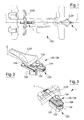
figure 1 is a plan view of an adjusting group according to the invention, with some parts removed for the sake of clarity; -
figure 2 is a schematic perspective view, in enlarged scale and with some parts removed for the sake of clarity, of a first portion offigure 1 ; -
figure 3 is a schematic perspective view, in enlarged scale and with some parts removed for the sake of clarity, of a second portion offigure 1 ; -
figure 4 is a longitudinal cross-section of a detail visible infigure 2 and figure 3 ; -
figure 5 is an exploded perspective view offigure 3 ; -
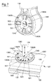
figures 6a and 6b are side elevation views of a first detail extracted fromfigure 2 (or figure 3 ) in two distinct operating configurations; -
figure 7 is an exploded view, in enlarged scale and with some parts removed for the sake of clarity, of two components, shown coupled infigures 6a and 6b ; -
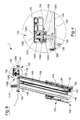
figure 8 is a longitudinal cross-section offigure 2 , with some parts removed for the sake of clarity; and -
figure 9 is a longitudinal cross-section offigure 3 , with some parts removed for the sake of clarity. - In figures from 1 to 3,
number 100 indicates a gymnastic machine provided with aframe 102 supporting a pair of user-interfaces 2 that can be used by a user to take position on the machine, adopting an adequate posture to perform a customized training session. Anadjusting group 1 is associated with each user-interface 2, designed to adjust the longitudinal and vertical position of the corresponding user-interface 2 relative to the frame. Each adjustinggroup 1 comprises asliding coupling unit 120, defining a substantially rectilinear first path L for adjusting the position of the respective user-interface 2 with respect to theframe 102. Afirst blocking device 130 is provided in combination with thecoupling unit 120 to fix the corresponding user-interface 2 in any position along the first path (L). Thecoupling unit 120 comprises aguide 122 associated with theframe 102 and aslide 124 associated with the user-interface 2 and coupled to theguide 122 in sliding fashion along respectivefirst coupling surface 1220 of theguide 122 andsecond coupling surface 1240 of theslide 124. Eachfirst blocking device 130 is carried by therespective slide 124 to facilitate the adjustment of the position of the corresponding user-interface 2. As it is visible infigure 5 , theguide 122 and theslide 124 may be built using portions of extruded bars of substantially conjugated shape, made of rigid resistant materials of limited density, such as aluminium or the like. - At this point, it should be noted that the
gymnastic machine 100, with which at least one adjustinggroup 1 has been associated, is a stationary bike, of the type used for spinning or for performing exercises in training groups or classes, that will be indicated below with thesame number 100, without however limiting the general scope of the invention. Thebike 100 comprises two user-interfaces 2, in particular a saddle 22 and a handlebar 20; arespective adjusting group 1 is associated with each user-interface. In particular, thefirst blocking device 130 associated with the saddle 22 is arranged behind the saddle 22 according to the direction L, i.e. it is arranged, in use, behind the user, while thefirst blocking device 130 associated with the handlebar 20 is aligned with the direction L from the user's side, i.e. it can be accessed without interfering with the user's legs and always at the same distance from the corresponding user-interface 2 (handlebar 20 or saddle 22). With particular reference tofigure 4 , thefirst blocking device 130 comprises apin 136 arranged transversally to the first path L through theslide 124. Thepin 136 has abody 1360 engaging a longitudinal groove 1222 (figure 5 ) provided in substantially central position in theguide 122; thisbody 1360 is delimited, at the side of theslide 124, by a threadedportion 1362, and engages theguide 122 with arespective end portion 132, shaped like a square plate. Essentially, thisplate 132 is a blockingmember 132 that may be rigidly fastened to the body 1360 (of the pin 136) or may be freely coupled to thebody 1360. Due to the high simplicity of the application, in this case, not shown in the attached figures for the sake of drawing practicality, thebody 1360 is shaped like a known flat-head screw; it is therefore provided with a head of greater dimension than that of thebody 1360, whose aim is only to act as lower abutment suitable to axially hold a plate externally shaped like theplate 132 but equipped with a central hole allowing it to be axially coupled to thebody 1360 of thepin 136 and to take an axially defined position, into tangential contact with the inner face of the screw head. - With particular reference to
figures 4 and7 again, eachfirst blocking device 130 furthermore comprises an actuating device provided with a pair with inclined plane, the actuating device and the pair being indicated, for the sake of practicality, with thesame reference number 138. Thispair 138 is provided with afirst body 1380 and with asecond body 1382, that extend peripherally around therespective pin 136. Thefirst body 1380 is rigidly coupled to ahandle 134 and has ahole 1340 engaged by thebody 1360; thehandle 134 has acavity 1342 housing anut 1344, with which the threadedportion 1362 is screwed. Thiscavity 1342 is closed by means of alid 135, held in position by a screw member, shown in the drawing without reference number for the sake of drawing economy. Thesecond body 1382 is rigidly connected to theslide 124. With particular reference tofigure 4 , the connection between thesecond body 1382 and theslide 124 is provided by means of amechanical coupling 1383, i.e. a shape coupling between thesecond body 1382 and theslide 124, without however limiting the scope of the invention. With particular reference tofigure 7 , the first and thesecond bodies first surface 1380S with inclined plane andsecond surface 1382S with inclined plane. Thisfirst surface 1380S and thissecond surface 1382S are shaped in a substantially conjugated fashion and are toothed, i.e. they have projections (or teeth) 1380A and 1382A, in equal number, extending vertically infigure 4 . - In particular, with reference to
figure 7 , eachtooth 1382A extends from a substantially horizontal plane S21 having an inclined portion S22 followed by a substantially horizontal flat portion S23 and by an angular abutment B21. Taking into account that, for the sake of practicality, thehandle 134 has been illustrated vertical infigure 7 , even if, in use, it is usually in substantially horizontal position, eachtooth 1380A is shaped similarly to eachtooth 1382A, but without the angular abutment provided in the corresponding tooth thereof, to avoid undesired interferences. The respective inclined portion S02 extends from an upper level than that of a respective plane S01, homologous to the plane S21, and ends in a flat portion S03. With reference tofigure 4 , it should be noted that thefirst teeth 1380A and thesecond teeth 1382A have increasing thickness according to given angles oriented in the same manner. In view of the above description, the particular conformation and number of theteeth first body 1380 relative to thesecond body 1382 with a relative angular rotation of the first andsecond bodies first body 1380 corresponds a vertical movement of thefirst body 1380, and therefore of theslide 124, towards or away from theguide 122. Therefore, the particular conformation of theteeth second surfaces slide 124 with respect to theguide 122. - It is easily understood that the vertical position of the
pin 136 depends on the vertical position of thefirst body 1380 with respect to thesecond body 1382. On the other hand, the vertical position of thepin 136 is determined by the angular position of thefirst body 1380 with respect to thesecond body 1382, and thus by the angular position of thehandle 134, and on this position depends the condition of coupling or free sliding of theslide 124 with respect to theguide 122. - With particular reference to
figures 6a and 6b , the clockwise rotation of thehandle 134 causes the rotation of thefirst body 1380 on thesecond body 1382 and allows axially to switch the pin 136 (and therefore the plate 132) between a first stop operating position P1, wherein it keeps thefirst coupling surface 1220 and thesecond coupling surface 1240 into matching contact with each other and keeps theslide 124 firmly connected to theguide 122 and fixed relative to the frame 102 (position of theplate 132 shown infigure 6a ), and a second releasing operating position P2, wherein it frees thefirst coupling surface 1220 and thesecond coupling surface 1240 from each other and makes theslide 124 free to slide relative to theguide 122, to find the correct adjusting position for the user-interface 2 relative to theframe 102 according to the user's current needs (position of theplate 132 shown infigure 6b ). Obviously, the counter-clockwise rotation of thehandle 134 causes thefirst body 1380 to raise with respect to thesecond body 1382 and thepin 136 to be positioned again in the respective position P2. - The
actuating handle 134, centred on thepin 136, is therefore suitable to switch theplate 132 between the first operating position P1 and the second operating position P2 by means of rotations on a circle arc whose width is, with reference tofigure 7 but without limiting the scope of the invention, lower than or equal to 90° in a given direction. Therefore, the direction of rotation to bring thepair 138 with inclined pair in the configuration offigure 6a or in the configuration offigure 6b is univocally identified. In this way, the reciprocal fastening of theslide 124 to theguide 122 is always determined, as well as the releasing thereof. - With particular reference to
figure 2 , theslide 124 carries the user-interface 2 and theactuating handle 134 adjacent to each other so that thehandle 134 can be accessed from the top always at the same distance from the user-interface 2 with which it is associated. This allows the training user to act on thefirst blocking device 130 with only one hand, making always the same gesture with reference to a same adjusting member, and therefore to have always at least one hand resting on the handlebar 20. Moreover, the particular conformation of thefirst blocking device 130 allows the user to find thehandle 134 always in the same given position behind the saddle 22 or behind the handlebar 20, independently of the position taken by these user-interfaces relative to theframe 102. It is easily understood that this feature allow to balance the user's posture during all the training steps, even if interspersed with steps where the positions of the user-interfaces 2 are changed so as to allow to take different postures, more suitable to the exercise to be performed. - Obviously, the scope of the present invention also comprises the case, not shown, wherein the
second body 1382 is carried angularly movable with respect to theslide 124 through thehandle 134, while thefirst body 1380 is held angularly fixed. - With particular reference to
figure 8 , theframe 102 comprises asleeve 104 extending according to a first given direction D, substantially transversal to the path L, and housing, in an axially sliding fashion, anelongated member 106 delimited at the top by theguide 122. Asecond blocking device 140 is arranged between theelongated member 106 and thesleeve 104 to hold theguide 122 in a given position relative to theframe 102. In particular, thesecond blocking device 140 comprises atoothed rack 142, carried by thesleeve 104 in a rigid way, atoothed member 144, carried by theelongated member 106 in a tilting way, and aswitching device 150 to switch the position of thetoothed member 144 from an engaging position, wherein thetoothed member 144 stably engages any space of thetoothed rack 142, and a non-engaging position, wherein thetoothed member 144 is arranged completely outside the spaces of thetoothed rack 142. - It should be specified that the
toothed rack 142 has respective spaces shaped like right-angled triangles, with the smaller leg facing the user-interface 2. In this way, in use, thetoothed member 144 can freely slide on the profile of thetoothed rack 142 to move theguide 122 upwards. Thesecond blocking device 140 comprises anelastic return member 146 connected to thetoothed member 144 to return thetoothed member 144 from the non-engaging position to the engaging position of any of the spaces of thetoothed rack 142, to allow the automatic engaging thereof. Theswitching device 150 comprises ahandle 148 carried by theelongated member 106 at the side of theguide 122 and connected to thetoothed member 144 by means of arod 149. - The use of the
adjusting group 1 and of thebike 100 comprising two adjusting groups, in combination, respectively, with the respective saddle 22 and the respective handlebar 20, is clearly apparent from the description above and does not require further explanation. - However, it could be useful to highlight that the features of the
first blocking device 130 allow eachadjusting group 1 to be actuated with only one hand, making always the same gesture with reference to an actuating member (the handle 134) arranged at constant distance from the user-interface (handlebar 20 or saddle 22), whose longitudinal position shall be adjusted while performing an exercise. - Lastly, it is clearly apparent that variants and modifications can be done to the
adjusting group 1 and thebike 100 described and illustrated herein without however departing from the protective scope of the invention. - For instance, the blocking position of
guide 122 and slide 124 can be also provided through afirst surface 1380S and asecond surface 1382S shaped in symmetric fashion (not shown), wherein the first tooth 1380' and the second tooth 1382' have a central cusp. In this way, the rotation for fastening theslide 124 to theguide 122 can be done in correspondence of the cusp, and thus on a circle arc of very reduced width and can be indifferently clockwise or counter-clockwise. Moreover, in this way the blocking position of the user-interfaces 2 can be "metastatic", as a minimal rotation of the actuatingmember 134 in one of the two directions would cause the undesired releasing of theslide 124 from theguide 122, with consequent releasing of the reciprocal coupling and loss of a fixed reference, thus of the balance, for the user. - In view of the above description, the
bike 100 is provided with two adjustinggroups 1, allowing to adjust the position of the respective user-interface 2 while continuing the training session. In fact, while being sitting on the saddle 22 and continuing pedalling, it is possible to grip one of the two handles of the handlebar 20 with one hand, and to use the other hand to release thecorresponding slide 124 from theguide 122, acting on thecorresponding blocking device 132. In particular, thehandle 134 shall be rotated in a given direction (clockwise direction according to what shown infigures 6a and 6b , to bring theplate 132 from the position P1 to the position P2). At this point, the handlebar 20 is free and can be moved forward or backward with the same hand that has actuated thehandle 134, until it achieves the desired position, and can be easily fastened in the desired position by turning thehandle 134 in opposite direction with respect to the previous direction (counter-clockwise, to bring theplate 132 from the position P2 to the position P1). For the adjustment of the saddle 22, remaining on the pedals it is possible to release with one hand the correspondingfirst blocking device 130, to use the same hand for changing the position of the saddle 22 and to use the same hand again to block the saddle 20 in the new position, analogously to what described above with reference to the handlebar 20. - The adjustment of the vertical position of the saddle 22 and of the handlebar 20 (user-interfaces 2) can be done by directly raising them (in view of the above description), if necessary by previously releasing the corresponding
toothed member 144 through therespective handle 148, that keeps thetoothed member 144 outside the spaces of the respectivetoothed rack 142 while moving theguide 122 upwards; on the contrary, due to safety reasons, the lowering of the saddle 22 and the handlebar 20 is possible only by acting on thehandle 148, that allows also to adjust the position downward of the respective user-interface 2. - In view of the above description, it is easily understood that the adjusting
groups 1 for adjusting the position of the saddle 22 and the handlebar 20 can be safely used while executing the exercise, without the risk for the user to lose the balance or to interfere with the exercise to change the posture on the bike, and they are therefore suitable to the needs of people performing challenging spinning exercises. - In this way, the
bike 100 can be adapted to the user's sizes in a customized fashion also while performing an exercise during training. - In view of the above description it is clearly apparent that the
adjusting group 1 can be used in association with a saddle or a handlebar of stationary bikes of any model, as well as of bicycles used for daily transport or of bicycles used for races, without departing from the protective scope of the present invention.
Claims (14)
- Adjusting group (1) for adjusting the position of a user-interface (2) of a gymnastic machine (100) relative to a respective frame (102) thereof; first sliding coupling means (120) being associated with said user-interface (2) to define a first path (L) for adjusting the position of said user-interface (2) with respect to said frame (102); first blocking means (130) being provided in combination with said first coupling means (120) to fix said user-interface (2) in any position along said first path (L); said first coupling means (120) comprising a guide (122) associated with said frame (102) and a slide (124) associated with said user-interface (2) coupled to said guide (122) in a sliding fashion along respective first coupling surface (1220) and second coupling surface (1240); characterized in that said first blocking means (130) are carried by said slide (124).
- Group according to claim 1, characterized in that said first blocking means (130) are carried by said slide (124) at a constant distance from said user-interface (2).
- Group according to claim 1 or 2, characterized in that said first blocking means (130) comprise a blocking member (132) arranged between said guide (122) and said slide (124), carried movable transversally to said first path (L) between a first stop operating position (P1) in contact with said guide (122), wherein it keeps said first and second coupling surfaces (1220) (1240) into matching contact with each other and keeps said slide (124) firmly connected to said guide (122) and fixed relative to said frame (102), and a second releasing operating position (P2), wherein it frees said first and second coupling surfaces (1220)(1240) from each other and makes said slide (124) free to slide relative to said guide (122), to find the correct adjusting position for said user-interface (2) relative to said frame (102).
- Group according to claim 3, characterized in that said first blocking means (130) comprise a pin (136) which carries said blocking member (132), is associated with said user-interface (2) and is arranged transversally to said first path (L) through said guide (122) to connect said slide (124) and said guide (122) rigidly.
- Group according to claim 4, characterized in that said first blocking means (130) comprise an actuating device (138) able to influence the position of said pin (136) transversally to said slide (124) in order to switch the axial position thereof between the first and the second operating positions (P1, P2); an actuating member (134) being associated with said pin (136) to move it axially.
- Group according to claim 5, characterized in that said actuating device (138) comprises a pair (138) with inclined plane provided with a first body (1380), associated with said user-interface (2) in an angularly free manner, and a second body (1382) facing said first body (1380) and carried integral by said slide (124); said first and second bodies (1380) (1382) being delimited by respective first and second surfaces (1380S) (1382S) with inclined plane designed to be conjugated together so that, in use, to an angular displacement of said first body (1380) relative to said second body (1382) corresponds such a change in the axial position of said pin (136) to switch said blocking member (132) between said first and second operating positions (P1, P2).
- Group according to claim 6, characterized in that each said first and second surface (1380S)(1382S) with inclined plane extends peripherally around said pin (136) so that said actuating member (134) is able to switch said blocking member (132) between said first and second operating positions (P1, P2) by means of own rotations on a circle arc of given width.
- Group according to any one of claims 3-7, characterized in that said slide (124) carries said user-interface (2) and said actuating member (134) adjacent to each other so that said actuating member (134) can be accessed from the top at the side of said user-interface (2).
- Group according to any one of the previous claims, characterized in that said first path (L) is rectilinear and in that said frame (102) comprises a sleeve (104) extending according to a first given direction (D); said sleeve (104) housing, in an axially sliding fashion, an elongated member (106) delimited at the top by said guide (122); second blocking means (140) being arranged between said elongated member (106) and said sleeve (104) to hold said guide (122) in a given position relative to said frame (102); said second blocking means (140) comprising a toothed rack (142), carried by said sleeve (104) in a rigid way, a toothed member (144), carried by said elongated member (106) in a tilting way, and a switching device (150) to switch the position of said toothed member (144) from an engaging position, wherein said toothed member (144) stably engages any space of said toothed rack (142) and a non-engaging position, wherein said toothed member (144) is arranged completely outside said toothed rack (142).
- Group according to claim 9, characterized in that said toothed rack (142) has respective spaces shaped like right-angled triangles with the smaller leg facing said user-interface (2), in order to allow said toothed member (144) freely to slide, in use, on the profile of said toothed rack (142) to move said guide (122) upwards; said second blocking means (140) comprising an elastic return member (146) connected to said toothed member (144) to return said toothed member (144) from said non-engaging position to said engaging position of any of said spaces to allow automatic engaging of said toothed rack (142); said switching device (150) comprising a handle (148) carried by said elongated member at the side of said guide (122) and connected to said toothed member (144) by means of a rod (149).
- Group according to any one of the previous claims, characterized in that said user-interface (2) comprises a handlebar (20) or a saddle (22).
- Bicycle (200) characterized by comprising a first adjusting group as described in any one of claims 1-8, whose user-interface (2) is constituted by a saddle (22), and a second adjusting group as described in any one of claims 1-8, whose user-interface (2) is constituted by a handlebar (2).
- Method for adjusting the position of a user-interface (2) of a gymnastic machine (100) relative to a respective frame (102) thereof; said method comprising a step of defining a position of said user-interface (2) relative to said frame (102) along a first adjusting path (L) by means of first sliding coupling means (120); a step of fixing said user-interface (2) in any position along said first path (L) by means of first blocking means (130) able to interact with said first sliding coupling means (120); said first coupling means (120) comprising a guide (122) associated with said frame (102) and a slide (124) associated with said user-interface (2); characterized in that said step of fixing said user-interface (2) in any position along said first path (L) by means of first blocking means (130) comprises a sub-step of keeping said first blocking means (130) on said slide (124) at a constant distance from the corresponding user-interface (2).
- Method according to claim 13, characterized in that said sub-step of keeping said first blocking means (130) on said slide (124) at a constant distance from the corresponding user-interface (2) can be performed by means of a rigid connection between said user-interface (2) and said first blocking means (130).
Applications Claiming Priority (1)
| Application Number | Priority Date | Filing Date | Title |
|---|---|---|---|
| ITRA20140016 | 2014-09-12 |
Publications (3)
| Publication Number | Publication Date |
|---|---|
| EP2995356A2 true EP2995356A2 (en) | 2016-03-16 |
| EP2995356A3 EP2995356A3 (en) | 2016-06-08 |
| EP2995356B1 EP2995356B1 (en) | 2018-12-26 |
Family
ID=52101470
Family Applications (1)
| Application Number | Title | Priority Date | Filing Date |
|---|---|---|---|
| EP15184413.1A Active EP2995356B1 (en) | 2014-09-12 | 2015-09-09 | Gymnastic machine with adjusting group |
Country Status (4)
| Country | Link |
|---|---|
| US (1) | US9671062B2 (en) |
| EP (1) | EP2995356B1 (en) |
| CN (1) | CN105413111B (en) |
| ES (1) | ES2709373T3 (en) |
Families Citing this family (1)
| Publication number | Priority date | Publication date | Assignee | Title |
|---|---|---|---|---|
| US10010746B1 (en) * | 2016-12-22 | 2018-07-03 | Great Fitness Industrial Co., Ltd. | Seat adjustment structure for exercise machine |
Citations (1)
| Publication number | Priority date | Publication date | Assignee | Title |
|---|---|---|---|---|
| CN102530164A (en) | 2010-12-24 | 2012-07-04 | 昆山亚新鸿运动器材有限公司 | Movable handlebar of spinning |
Family Cites Families (26)
| Publication number | Priority date | Publication date | Assignee | Title |
|---|---|---|---|---|
| GB1402121A (en) * | 1972-01-31 | 1975-08-06 | Raleigh Industries Ltd | Bicycle fitting and exercising apparatus |
| US4807856A (en) * | 1987-10-08 | 1989-02-28 | Gary Teckenbrock | Adjustable bicycle seat post |
| US4772069A (en) * | 1987-12-24 | 1988-09-20 | Schwinn Bicycle Company | Longitudinally adjustable saddle mounting for cycle-type apparatus |
| US5649558A (en) * | 1995-09-27 | 1997-07-22 | Richard; Reginald L. | Accommodation walker for irregular and inclined surfaces |
| JP3432397B2 (en) * | 1996-12-20 | 2003-08-04 | 松下電器産業株式会社 | Bicycle with anti-theft device |
| US6752453B1 (en) * | 2003-03-29 | 2004-06-22 | Charles Yapp | Seat adjusting device of an exercising cycle |
| KR100672008B1 (en) * | 2005-09-09 | 2007-01-19 | 임정수 | A sporting equipment with height controllable seat |
| US7708251B2 (en) * | 2006-03-17 | 2010-05-04 | Nautilus, Inc. | Mechanism and method for adjusting seat height for exercise equipment |
| US20080096725A1 (en) * | 2006-10-20 | 2008-04-24 | Keiser Dennis L | Performance monitoring & display system for exercise bike |
| US7874615B2 (en) * | 2007-03-29 | 2011-01-25 | Brunswick Corporation | Recumbent seat mechanism |
| US8021278B2 (en) * | 2007-03-29 | 2011-09-20 | Brunswick Corporation | Seat mechanisms |
| US7762931B2 (en) * | 2007-04-18 | 2010-07-27 | Interactive Fitness Holdings, LLC | Seat for cardio-fitness equipment |
| US8092352B2 (en) * | 2007-08-17 | 2012-01-10 | Realryder, Llc | Bicycling exercise apparatus with multiple element load dispersion |
| US8951168B2 (en) * | 2008-03-05 | 2015-02-10 | Mad Dogg Athletics, Inc. | Programmable exercise bicycle |
| IT1390884B1 (en) * | 2008-09-29 | 2011-10-19 | Technogym Spa | ADJUSTMENT DEVICE |
| WO2010105223A1 (en) * | 2009-03-13 | 2010-09-16 | Nautilus, Inc. | Exercise bike |
| US9511809B2 (en) * | 2010-02-23 | 2016-12-06 | Shimano Inc. | Height adjustable seatpost assembly |
| US8628455B2 (en) * | 2011-01-05 | 2014-01-14 | Gee Hoo Fitec Corp. | Idler adjusting apparatus of exercise machine |
| TWM415719U (en) * | 2011-04-26 | 2011-11-11 | Gee Hoo Ind Corp | Multifunctional sitting type elliptical orbit fitness machine |
| US20150045190A1 (en) * | 2012-03-14 | 2015-02-12 | Keiser Corporation | Eccentric idler |
| CN202654602U (en) * | 2012-07-09 | 2013-01-09 | 宁波昌隆健身器材有限公司 | Exercise bicycle seat adjusting device |
| US20140112703A1 (en) * | 2012-10-18 | 2014-04-24 | Chao-Hu Chen | Adjustable seat tubing device for a bicycle |
| TWM454865U (en) * | 2012-11-23 | 2013-06-11 | Chiu-Hsiang Lo | Swing type fitness device |
| TWI486192B (en) * | 2012-12-12 | 2015-06-01 | Fitness equipment of the bracket adjustment device | |
| CN203169915U (en) * | 2012-12-12 | 2013-09-04 | 岱宇国际股份有限公司 | Support adjusting device of fitness equipment |
| TWM481759U (en) * | 2014-02-27 | 2014-07-11 | Bh Asia Ltd | Adjustable swing device of fitness bike |
-
2015
- 2015-09-09 EP EP15184413.1A patent/EP2995356B1/en active Active
- 2015-09-09 ES ES15184413T patent/ES2709373T3/en active Active
- 2015-09-10 US US14/850,299 patent/US9671062B2/en active Active
- 2015-09-11 CN CN201510575494.0A patent/CN105413111B/en active Active
Patent Citations (1)
| Publication number | Priority date | Publication date | Assignee | Title |
|---|---|---|---|---|
| CN102530164A (en) | 2010-12-24 | 2012-07-04 | 昆山亚新鸿运动器材有限公司 | Movable handlebar of spinning |
Also Published As
| Publication number | Publication date |
|---|---|
| EP2995356A3 (en) | 2016-06-08 |
| ES2709373T3 (en) | 2019-04-16 |
| CN105413111B (en) | 2019-07-26 |
| US20160076694A1 (en) | 2016-03-17 |
| CN105413111A (en) | 2016-03-23 |
| EP2995356B1 (en) | 2018-12-26 |
| US9671062B2 (en) | 2017-06-06 |
Similar Documents
| Publication | Publication Date | Title |
|---|---|---|
| US10576331B2 (en) | Composite motion exercise machine | |
| US20170252603A1 (en) | Stepper exercise machine | |
| EP3535032B1 (en) | Drop-in pivot configuration for stationary bike | |
| US8840529B2 (en) | Adjustable elliptical trainer | |
| US9744401B2 (en) | Multifunctional exercise machine | |
| US9616281B2 (en) | Crank for exercise equipment which helps prevent injuries on a rider's ankle during an unexpected drop in speed and assists in avoiding stress on the knees of a rider during exercising | |
| US10071298B1 (en) | Workout apparatus for simulating user movement patterns in bicycle sports | |
| US20160075389A1 (en) | Multiple Position Bicycle Seat Post | |
| US20170291062A1 (en) | Horse riding exercise machine | |
| US9375604B2 (en) | Adjustable pedal assembly for fitness machine | |
| US6616163B2 (en) | Combined skateboard scooter/exerciser | |
| KR101564841B1 (en) | Cycle for swimming practice and swimming motion | |
| US5913752A (en) | Total body exercise machine | |
| JP3176132U (en) | Bicycle auxiliary device | |
| EP2995356B1 (en) | Gymnastic machine with adjusting group | |
| KR101499823B1 (en) | Chamber pot of bicycle for health and standingtype | |
| US20130237385A1 (en) | Adjustable frame for excercise device | |
| NO20141492A1 (en) | torso support device | |
| WO2006004379A1 (en) | An apparatus for adjusting a position of a saddle of a bicycle | |
| CN208541737U (en) | Deep-knee-bend body stretching machine | |
| KR101715595B1 (en) | health bicycle handle | |
| US9295875B2 (en) | Recumbent stepper | |
| US20120326413A1 (en) | Arrangement for bicycle with combined movement | |
| CN201012251Y (en) | Multifunctional oval machine | |
| KR200431281Y1 (en) | A pedal apparatus of sport outfits |
Legal Events
| Date | Code | Title | Description |
|---|---|---|---|
| PUAI | Public reference made under article 153(3) epc to a published international application that has entered the european phase |
Free format text: ORIGINAL CODE: 0009012 |
|
| AK | Designated contracting states |
Kind code of ref document: A2 Designated state(s): AL AT BE BG CH CY CZ DE DK EE ES FI FR GB GR HR HU IE IS IT LI LT LU LV MC MK MT NL NO PL PT RO RS SE SI SK SM TR |
|
| AX | Request for extension of the european patent |
Extension state: BA ME |
|
| PUAL | Search report despatched |
Free format text: ORIGINAL CODE: 0009013 |
|
| AK | Designated contracting states |
Kind code of ref document: A3 Designated state(s): AL AT BE BG CH CY CZ DE DK EE ES FI FR GB GR HR HU IE IS IT LI LT LU LV MC MK MT NL NO PL PT RO RS SE SI SK SM TR |
|
| AX | Request for extension of the european patent |
Extension state: BA ME |
|
| RIC1 | Information provided on ipc code assigned before grant |
Ipc: A63B 22/00 20060101AFI20160429BHEP Ipc: A63B 22/06 20060101ALI20160429BHEP |
|
| STAA | Information on the status of an ep patent application or granted ep patent |
Free format text: STATUS: REQUEST FOR EXAMINATION WAS MADE |
|
| 17P | Request for examination filed |
Effective date: 20161111 |
|
| RAP1 | Party data changed (applicant data changed or rights of an application transferred) |
Owner name: TECHNOGYM S.P.A. |
|
| RBV | Designated contracting states (corrected) |
Designated state(s): AL AT BE BG CH CY CZ DE DK EE ES FI FR GB GR HR HU IE IS IT LI LT LU LV MC MK MT NL NO PL PT RO RS SE SI SK SM TR |
|
| STAA | Information on the status of an ep patent application or granted ep patent |
Free format text: STATUS: EXAMINATION IS IN PROGRESS |
|
| 17Q | First examination report despatched |
Effective date: 20180219 |
|
| GRAP | Despatch of communication of intention to grant a patent |
Free format text: ORIGINAL CODE: EPIDOSNIGR1 |
|
| STAA | Information on the status of an ep patent application or granted ep patent |
Free format text: STATUS: GRANT OF PATENT IS INTENDED |
|
| INTG | Intention to grant announced |
Effective date: 20180725 |
|
| GRAS | Grant fee paid |
Free format text: ORIGINAL CODE: EPIDOSNIGR3 |
|
| GRAA | (expected) grant |
Free format text: ORIGINAL CODE: 0009210 |
|
| STAA | Information on the status of an ep patent application or granted ep patent |
Free format text: STATUS: THE PATENT HAS BEEN GRANTED |
|
| AK | Designated contracting states |
Kind code of ref document: B1 Designated state(s): AL AT BE BG CH CY CZ DE DK EE ES FI FR GB GR HR HU IE IS IT LI LT LU LV MC MK MT NL NO PL PT RO RS SE SI SK SM TR |
|
| REG | Reference to a national code |
Ref country code: GB Ref legal event code: FG4D |
|
| REG | Reference to a national code |
Ref country code: CH Ref legal event code: EP |
|
| REG | Reference to a national code |
Ref country code: AT Ref legal event code: REF Ref document number: 1080609 Country of ref document: AT Kind code of ref document: T Effective date: 20190115 |
|
| REG | Reference to a national code |
Ref country code: DE Ref legal event code: R096 Ref document number: 602015022160 Country of ref document: DE |
|
| REG | Reference to a national code |
Ref country code: IE Ref legal event code: FG4D |
|
| REG | Reference to a national code |
Ref country code: ES Ref legal event code: FG2A Ref document number: 2709373 Country of ref document: ES Kind code of ref document: T3 Effective date: 20190416 |
|
| REG | Reference to a national code |
Ref country code: NL Ref legal event code: FP |
|
| PG25 | Lapsed in a contracting state [announced via postgrant information from national office to epo] |
Ref country code: FI Free format text: LAPSE BECAUSE OF FAILURE TO SUBMIT A TRANSLATION OF THE DESCRIPTION OR TO PAY THE FEE WITHIN THE PRESCRIBED TIME-LIMIT Effective date: 20181226 Ref country code: NO Free format text: LAPSE BECAUSE OF FAILURE TO SUBMIT A TRANSLATION OF THE DESCRIPTION OR TO PAY THE FEE WITHIN THE PRESCRIBED TIME-LIMIT Effective date: 20190326 Ref country code: LT Free format text: LAPSE BECAUSE OF FAILURE TO SUBMIT A TRANSLATION OF THE DESCRIPTION OR TO PAY THE FEE WITHIN THE PRESCRIBED TIME-LIMIT Effective date: 20181226 Ref country code: HR Free format text: LAPSE BECAUSE OF FAILURE TO SUBMIT A TRANSLATION OF THE DESCRIPTION OR TO PAY THE FEE WITHIN THE PRESCRIBED TIME-LIMIT Effective date: 20181226 Ref country code: LV Free format text: LAPSE BECAUSE OF FAILURE TO SUBMIT A TRANSLATION OF THE DESCRIPTION OR TO PAY THE FEE WITHIN THE PRESCRIBED TIME-LIMIT Effective date: 20181226 Ref country code: BG Free format text: LAPSE BECAUSE OF FAILURE TO SUBMIT A TRANSLATION OF THE DESCRIPTION OR TO PAY THE FEE WITHIN THE PRESCRIBED TIME-LIMIT Effective date: 20190326 |
|
| REG | Reference to a national code |
Ref country code: LT Ref legal event code: MG4D |
|
| PG25 | Lapsed in a contracting state [announced via postgrant information from national office to epo] |
Ref country code: AL Free format text: LAPSE BECAUSE OF FAILURE TO SUBMIT A TRANSLATION OF THE DESCRIPTION OR TO PAY THE FEE WITHIN THE PRESCRIBED TIME-LIMIT Effective date: 20181226 Ref country code: SE Free format text: LAPSE BECAUSE OF FAILURE TO SUBMIT A TRANSLATION OF THE DESCRIPTION OR TO PAY THE FEE WITHIN THE PRESCRIBED TIME-LIMIT Effective date: 20181226 Ref country code: GR Free format text: LAPSE BECAUSE OF FAILURE TO SUBMIT A TRANSLATION OF THE DESCRIPTION OR TO PAY THE FEE WITHIN THE PRESCRIBED TIME-LIMIT Effective date: 20190327 Ref country code: RS Free format text: LAPSE BECAUSE OF FAILURE TO SUBMIT A TRANSLATION OF THE DESCRIPTION OR TO PAY THE FEE WITHIN THE PRESCRIBED TIME-LIMIT Effective date: 20181226 |
|
| REG | Reference to a national code |
Ref country code: AT Ref legal event code: MK05 Ref document number: 1080609 Country of ref document: AT Kind code of ref document: T Effective date: 20181226 |
|
| PG25 | Lapsed in a contracting state [announced via postgrant information from national office to epo] |
Ref country code: PT Free format text: LAPSE BECAUSE OF FAILURE TO SUBMIT A TRANSLATION OF THE DESCRIPTION OR TO PAY THE FEE WITHIN THE PRESCRIBED TIME-LIMIT Effective date: 20190426 Ref country code: CZ Free format text: LAPSE BECAUSE OF FAILURE TO SUBMIT A TRANSLATION OF THE DESCRIPTION OR TO PAY THE FEE WITHIN THE PRESCRIBED TIME-LIMIT Effective date: 20181226 Ref country code: PL Free format text: LAPSE BECAUSE OF FAILURE TO SUBMIT A TRANSLATION OF THE DESCRIPTION OR TO PAY THE FEE WITHIN THE PRESCRIBED TIME-LIMIT Effective date: 20181226 |
|
| PG25 | Lapsed in a contracting state [announced via postgrant information from national office to epo] |
Ref country code: SM Free format text: LAPSE BECAUSE OF FAILURE TO SUBMIT A TRANSLATION OF THE DESCRIPTION OR TO PAY THE FEE WITHIN THE PRESCRIBED TIME-LIMIT Effective date: 20181226 Ref country code: SK Free format text: LAPSE BECAUSE OF FAILURE TO SUBMIT A TRANSLATION OF THE DESCRIPTION OR TO PAY THE FEE WITHIN THE PRESCRIBED TIME-LIMIT Effective date: 20181226 Ref country code: RO Free format text: LAPSE BECAUSE OF FAILURE TO SUBMIT A TRANSLATION OF THE DESCRIPTION OR TO PAY THE FEE WITHIN THE PRESCRIBED TIME-LIMIT Effective date: 20181226 Ref country code: IS Free format text: LAPSE BECAUSE OF FAILURE TO SUBMIT A TRANSLATION OF THE DESCRIPTION OR TO PAY THE FEE WITHIN THE PRESCRIBED TIME-LIMIT Effective date: 20190426 Ref country code: EE Free format text: LAPSE BECAUSE OF FAILURE TO SUBMIT A TRANSLATION OF THE DESCRIPTION OR TO PAY THE FEE WITHIN THE PRESCRIBED TIME-LIMIT Effective date: 20181226 |
|
| REG | Reference to a national code |
Ref country code: DE Ref legal event code: R097 Ref document number: 602015022160 Country of ref document: DE |
|
| PG25 | Lapsed in a contracting state [announced via postgrant information from national office to epo] |
Ref country code: DK Free format text: LAPSE BECAUSE OF FAILURE TO SUBMIT A TRANSLATION OF THE DESCRIPTION OR TO PAY THE FEE WITHIN THE PRESCRIBED TIME-LIMIT Effective date: 20181226 Ref country code: AT Free format text: LAPSE BECAUSE OF FAILURE TO SUBMIT A TRANSLATION OF THE DESCRIPTION OR TO PAY THE FEE WITHIN THE PRESCRIBED TIME-LIMIT Effective date: 20181226 |
|
| PLBE | No opposition filed within time limit |
Free format text: ORIGINAL CODE: 0009261 |
|
| STAA | Information on the status of an ep patent application or granted ep patent |
Free format text: STATUS: NO OPPOSITION FILED WITHIN TIME LIMIT |
|
| 26N | No opposition filed |
Effective date: 20190927 |
|
| PG25 | Lapsed in a contracting state [announced via postgrant information from national office to epo] |
Ref country code: SI Free format text: LAPSE BECAUSE OF FAILURE TO SUBMIT A TRANSLATION OF THE DESCRIPTION OR TO PAY THE FEE WITHIN THE PRESCRIBED TIME-LIMIT Effective date: 20181226 |
|
| PG25 | Lapsed in a contracting state [announced via postgrant information from national office to epo] |
Ref country code: TR Free format text: LAPSE BECAUSE OF FAILURE TO SUBMIT A TRANSLATION OF THE DESCRIPTION OR TO PAY THE FEE WITHIN THE PRESCRIBED TIME-LIMIT Effective date: 20181226 |
|
| PG25 | Lapsed in a contracting state [announced via postgrant information from national office to epo] |
Ref country code: MC Free format text: LAPSE BECAUSE OF FAILURE TO SUBMIT A TRANSLATION OF THE DESCRIPTION OR TO PAY THE FEE WITHIN THE PRESCRIBED TIME-LIMIT Effective date: 20181226 |
|
| REG | Reference to a national code |
Ref country code: CH Ref legal event code: PL |
|
| PG25 | Lapsed in a contracting state [announced via postgrant information from national office to epo] |
Ref country code: LI Free format text: LAPSE BECAUSE OF NON-PAYMENT OF DUE FEES Effective date: 20190930 Ref country code: IE Free format text: LAPSE BECAUSE OF NON-PAYMENT OF DUE FEES Effective date: 20190909 Ref country code: CH Free format text: LAPSE BECAUSE OF NON-PAYMENT OF DUE FEES Effective date: 20190930 Ref country code: LU Free format text: LAPSE BECAUSE OF NON-PAYMENT OF DUE FEES Effective date: 20190909 |
|
| REG | Reference to a national code |
Ref country code: BE Ref legal event code: MM Effective date: 20190930 |
|
| PG25 | Lapsed in a contracting state [announced via postgrant information from national office to epo] |
Ref country code: BE Free format text: LAPSE BECAUSE OF NON-PAYMENT OF DUE FEES Effective date: 20190930 |
|
| PG25 | Lapsed in a contracting state [announced via postgrant information from national office to epo] |
Ref country code: CY Free format text: LAPSE BECAUSE OF FAILURE TO SUBMIT A TRANSLATION OF THE DESCRIPTION OR TO PAY THE FEE WITHIN THE PRESCRIBED TIME-LIMIT Effective date: 20181226 |
|
| PG25 | Lapsed in a contracting state [announced via postgrant information from national office to epo] |
Ref country code: MT Free format text: LAPSE BECAUSE OF FAILURE TO SUBMIT A TRANSLATION OF THE DESCRIPTION OR TO PAY THE FEE WITHIN THE PRESCRIBED TIME-LIMIT Effective date: 20181226 Ref country code: HU Free format text: LAPSE BECAUSE OF FAILURE TO SUBMIT A TRANSLATION OF THE DESCRIPTION OR TO PAY THE FEE WITHIN THE PRESCRIBED TIME-LIMIT; INVALID AB INITIO Effective date: 20150909 |
|
| PG25 | Lapsed in a contracting state [announced via postgrant information from national office to epo] |
Ref country code: MK Free format text: LAPSE BECAUSE OF FAILURE TO SUBMIT A TRANSLATION OF THE DESCRIPTION OR TO PAY THE FEE WITHIN THE PRESCRIBED TIME-LIMIT Effective date: 20181226 |
|
| P01 | Opt-out of the competence of the unified patent court (upc) registered |
Effective date: 20230601 |
|
| PGFP | Annual fee paid to national office [announced via postgrant information from national office to epo] |
Ref country code: NL Payment date: 20230926 Year of fee payment: 9 Ref country code: IT Payment date: 20230920 Year of fee payment: 9 Ref country code: GB Payment date: 20230926 Year of fee payment: 9 |
|
| PGFP | Annual fee paid to national office [announced via postgrant information from national office to epo] |
Ref country code: FR Payment date: 20230926 Year of fee payment: 9 Ref country code: DE Payment date: 20230928 Year of fee payment: 9 |
|
| PGFP | Annual fee paid to national office [announced via postgrant information from national office to epo] |
Ref country code: ES Payment date: 20231017 Year of fee payment: 9 |