EP2995156B1 - Verbesserte handhabung einer netzwerkkommunikationsübertragung mit gleichzeitigem d2d-kommunikationsempfangs oder eines netzwerkkommunikationsempfangs mit gleichzeitiger d2d-kommunikationsübertragung - Google Patents
Verbesserte handhabung einer netzwerkkommunikationsübertragung mit gleichzeitigem d2d-kommunikationsempfangs oder eines netzwerkkommunikationsempfangs mit gleichzeitiger d2d-kommunikationsübertragung Download PDFInfo
- Publication number
- EP2995156B1 EP2995156B1 EP13814060.3A EP13814060A EP2995156B1 EP 2995156 B1 EP2995156 B1 EP 2995156B1 EP 13814060 A EP13814060 A EP 13814060A EP 2995156 B1 EP2995156 B1 EP 2995156B1
- Authority
- EP
- European Patent Office
- Prior art keywords
- radio frequency
- transmission
- communication device
- frequency communication
- network
- Prior art date
- Legal status (The legal status is an assumption and is not a legal conclusion. Google has not performed a legal analysis and makes no representation as to the accuracy of the status listed.)
- Active
Links
- 238000004891 communication Methods 0.000 title claims description 323
- 230000005540 biological transmission Effects 0.000 title claims description 159
- 230000001976 improved effect Effects 0.000 title description 3
- 238000000034 method Methods 0.000 claims description 61
- 230000000116 mitigating effect Effects 0.000 claims description 53
- 230000015654 memory Effects 0.000 claims description 16
- 230000008054 signal transmission Effects 0.000 claims description 5
- 230000000630 rising effect Effects 0.000 claims description 4
- 230000003247 decreasing effect Effects 0.000 claims description 3
- 238000001514 detection method Methods 0.000 claims description 3
- 230000001413 cellular effect Effects 0.000 description 58
- 238000012913 prioritisation Methods 0.000 description 10
- 238000005259 measurement Methods 0.000 description 8
- 238000001228 spectrum Methods 0.000 description 8
- 101150071746 Pbsn gene Proteins 0.000 description 6
- 230000008859 change Effects 0.000 description 6
- 238000010295 mobile communication Methods 0.000 description 6
- 230000004044 response Effects 0.000 description 6
- 238000013459 approach Methods 0.000 description 5
- 238000005516 engineering process Methods 0.000 description 5
- 238000012545 processing Methods 0.000 description 5
- 241000760358 Enodes Species 0.000 description 4
- 230000010267 cellular communication Effects 0.000 description 4
- 238000007429 general method Methods 0.000 description 4
- 230000003595 spectral effect Effects 0.000 description 4
- 230000007774 longterm Effects 0.000 description 3
- 238000007476 Maximum Likelihood Methods 0.000 description 2
- 230000004913 activation Effects 0.000 description 2
- 230000006978 adaptation Effects 0.000 description 2
- 230000008901 benefit Effects 0.000 description 2
- 230000015556 catabolic process Effects 0.000 description 2
- 239000002131 composite material Substances 0.000 description 2
- 230000009849 deactivation Effects 0.000 description 2
- 238000006731 degradation reaction Methods 0.000 description 2
- 230000003287 optical effect Effects 0.000 description 2
- 230000001960 triggered effect Effects 0.000 description 2
- 230000009471 action Effects 0.000 description 1
- 230000009286 beneficial effect Effects 0.000 description 1
- 238000004590 computer program Methods 0.000 description 1
- 238000013500 data storage Methods 0.000 description 1
- 230000000694 effects Effects 0.000 description 1
- 230000002349 favourable effect Effects 0.000 description 1
- 230000000977 initiatory effect Effects 0.000 description 1
- 238000012423 maintenance Methods 0.000 description 1
- 238000013178 mathematical model Methods 0.000 description 1
- 239000011159 matrix material Substances 0.000 description 1
- 230000006855 networking Effects 0.000 description 1
- 230000005855 radiation Effects 0.000 description 1
- 230000001360 synchronised effect Effects 0.000 description 1
- 230000000007 visual effect Effects 0.000 description 1
Images


Classifications
-
- H—ELECTRICITY
- H04—ELECTRIC COMMUNICATION TECHNIQUE
- H04W—WIRELESS COMMUNICATION NETWORKS
- H04W52/00—Power management, e.g. TPC [Transmission Power Control], power saving or power classes
- H04W52/04—TPC
- H04W52/38—TPC being performed in particular situations
- H04W52/383—TPC being performed in particular situations power control in peer-to-peer links
-
- H—ELECTRICITY
- H04—ELECTRIC COMMUNICATION TECHNIQUE
- H04W—WIRELESS COMMUNICATION NETWORKS
- H04W72/00—Local resource management
- H04W72/50—Allocation or scheduling criteria for wireless resources
- H04W72/54—Allocation or scheduling criteria for wireless resources based on quality criteria
- H04W72/541—Allocation or scheduling criteria for wireless resources based on quality criteria using the level of interference
-
- H—ELECTRICITY
- H04—ELECTRIC COMMUNICATION TECHNIQUE
- H04W—WIRELESS COMMUNICATION NETWORKS
- H04W72/00—Local resource management
- H04W72/50—Allocation or scheduling criteria for wireless resources
- H04W72/535—Allocation or scheduling criteria for wireless resources based on resource usage policies
-
- H—ELECTRICITY
- H04—ELECTRIC COMMUNICATION TECHNIQUE
- H04W—WIRELESS COMMUNICATION NETWORKS
- H04W72/00—Local resource management
- H04W72/50—Allocation or scheduling criteria for wireless resources
- H04W72/56—Allocation or scheduling criteria for wireless resources based on priority criteria
-
- H—ELECTRICITY
- H04—ELECTRIC COMMUNICATION TECHNIQUE
- H04W—WIRELESS COMMUNICATION NETWORKS
- H04W76/00—Connection management
- H04W76/10—Connection setup
- H04W76/14—Direct-mode setup
-
- H—ELECTRICITY
- H04—ELECTRIC COMMUNICATION TECHNIQUE
- H04W—WIRELESS COMMUNICATION NETWORKS
- H04W76/00—Connection management
- H04W76/10—Connection setup
- H04W76/15—Setup of multiple wireless link connections
-
- H—ELECTRICITY
- H04—ELECTRIC COMMUNICATION TECHNIQUE
- H04W—WIRELESS COMMUNICATION NETWORKS
- H04W52/00—Power management, e.g. TPC [Transmission Power Control], power saving or power classes
- H04W52/04—TPC
- H04W52/06—TPC algorithms
- H04W52/14—Separate analysis of uplink or downlink
- H04W52/146—Uplink power control
-
- H—ELECTRICITY
- H04—ELECTRIC COMMUNICATION TECHNIQUE
- H04W—WIRELESS COMMUNICATION NETWORKS
- H04W88/00—Devices specially adapted for wireless communication networks, e.g. terminals, base stations or access point devices
- H04W88/02—Terminal devices
- H04W88/04—Terminal devices adapted for relaying to or from another terminal or user
Definitions
- This application relates to a method, a network node, a communication device, and a computer-readable storage medium for improved handling of simultaneous network communication transmission and D2D communication reception or simultaneous network communication reception and D2D communication transmission, and in particular to a method, a network node, a communication device and a computer-readable storage medium for improved handling of simultaneous network communication transmission and D2D communication reception or simultaneous network communication reception and D2D communication transmission by mitigating transmission problems in network assisted device-to-device communication networks.
- the present invention relates to Device-to-Device (D2D) Communications in the Cellular Spectrum.
- D2D Device-to-Device
- the concept of allowing local D2D communications to (re)use cellular spectrum resources simultaneously with ongoing cellular traffic is relatively new. Because the non-orthogonal resource sharing between the cellular and the D2D layers has the potential of the reuse gain and proximity gain at the same time increasing the resource utilization, D2D communications underlying cellular networks has received considerable interest in the recent years.
- LTE Direct (D2D) communication can be used in commercial applications, such as cellular network offloading, proximity based social networking, or in public safety situations in which first responders need to communicate with each other and with people in the disaster area.
- D2D LTE Direct
- D2D communication entities using an LTE Direct link may reuse the same physical resource blocks (PRB) as used for cellular communications either in the downlink or in the uplink or both.
- PRB physical resource blocks
- the reuse of radio resources in a controlled fashion can lead to the increase of spectral efficiency at the expense of some increase of the intra-cell interference.
- D2D communicating entities use UL resources such as UL PRBs or UL time slots, but conceptually it is possible that D2D (LTE Direct) communications takes place in the cellular DL spectrum or in DL time slots.
- D2D links use uplink resources, such as uplink PRBs in an FDD or uplink time slots in an a cellular TDD system, but the main ideas would carry over to cases in which D2D communications take place in DL spectrum as well.
- Figure 3 shows a principal schematic sketch over a network assisted D2D system.
- One or more network nodes 310 are in control over at least one radio frequency communication device 320, 325 and 327(also referenced D1, D2 and D3), of which at least two (320 D1 and 325 D2) are also is involved with D2D communication with each other.
- the network node 310 allocates time-frequency resources for D2D transmission, and is also in control over maximum allowed transmission (TX) power used in the D2D communication.
- TX maximum allowed transmission
- the network node 310 allocates D2D resources for approximately 200-500 ms and during that time period, then each radio frequency communication device 320, 325 makes autonomous selections of MCS (modulation and coding scheme) and executes commands such as HARQ (hybrid automatic repeat request).
- MCS modulation and coding scheme
- HARQ hybrid automatic repeat request
- the radio frequency communication device 320 reports signal quality status and/or other transmission quality measures, and receives new D2D resources to use for the next time period (i.e. 200-500 ms).
- UpLink (UL) spectrum/resources are used for D2D, as this is beneficial from an interference control perspective.
- D2D communication will typically not take up too much of the spectrum resources into account, it is far from efficient to allocate an entire frequency bandwidth in a sub frame for D2D communication.
- both UL (and Downlink (DL)) traffic and D2D traffic need to able to share the same sub frames, for example sharing a frequency.
- Such sharing of same sub frame for UL (or DL) communication (controlled by a network node) and D2D communication (as the radio frequency communication device autonomously decides when to transmit and to receive in a sub frame) might imply that a radio frequency communication device might need to transmit to the network node while simultaneously receiving D2D communication from a second radio frequency communication device in the same sub frame.
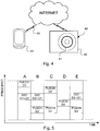
- Figure 5 shows an example of how simultaneous cellular and D2D allocation in the UL can be made.
- the first radio frequency communication device 320 D1 receives data over a D2D link and simultaneously transmits a physical uplink control channel (PUCCH) to the network node 310.
- the second radio frequency communication device 325 D2 transmits a physical UL shared channel (PUSCH) to the network node 310 and simultaneously receives information from the first radio frequency communication device 320 D1.
- PUSCH physical UL shared channel
- both the first radio frequency communication device 320 D1 and the third radio frequency communication device 327D3 transmit a PUSCH respectively to the network node 310.
- the second radio frequency communication device 325 D2 transmits a physical UL shared channel (PUSCH) to the network node 310, while in time period E, the second radio frequency communication device 325 D2 transmit to the first radio frequency communication device 325 D1 in D2D and the third radio frequency communication device 327 D3 transmit a PUSCH to the network node 310.
- PUSCH physical UL shared channel
- ACI Adjacent Channel Leakage Power ration
- Figures 6A and 6B illustrate a problem that may arise due to such in-band emission (for instance LTE 20 MHz).
- the first radio frequency communication device 320 D1 transmits a PUCCH to the network node 310 (referenced D1->NW) and at the same time also receives data in D2D mode from the second radio frequency communication device 325 D2 (referenced D1 ⁇ -D2). Assuming the PUCCH is transmitted with higher power than the D2D part is received at (due to e.g.
- the D2D reception may be affected by transmission (TX) leakage (referenced LA) from the PUCCH transmission.
- TX transmission
- LA transmission leakage
- the transmission on a first set of Resource Blocks (RBs) gives rise to spectral emission on adjacent RBs within the system frequency band, so- called ACI.
- the received signal may still be 10ths of dB below that level and hence buried in noise and undetectable by the device.
- One prior art method to solve this problem is to always avoid scheduling UL (and DL) resources to a device in a same sub frame as ongoing D2D communication.
- UL and DL resources
- US2004/240404 discloses a method for use by one peer of peer wireless interfaces devices of a wireless communication device to cooperatively provide wireless communications in a multiple wireless communication environment with other peers of the peer wireless interface devices begins by initiating an atomic sequence of a plurality of atomic sequences. The processing continues by setting a priority level corresponding to the atomic sequence to produce a corresponding priority level. The processing continues by sensing priority level of at least one of the other peers to produce a sensed priority level. The processing continues by comparing the sensed priority level with the corresponding priority level. The processing then continues by performing at least a portion of the atomic sequence when the comparing of the sensed priority level with the corresponding priority level is favorable.
- US2013/012191 discloses a method and apparatus are provided that may enable the provision of machine to machine (M2M) communication in a wireless network environment.
- M2M machine to machine
- relatively low power devices such as sensors or other machines in an M2M system may be enabled to communicate with a mobile terminal via a first carrier when the power ratio between the average received machine power and the average downlink received cellular power is below a threshold value and communicate with the mobile terminal via a second carrier if the power ratio exceeds the threshold value.
- only one carrier may be needed by devices in such an environment in order to perform M2M communication.
- the problem arises in situations when a radio frequency communication device in so called network (NW) assisted device-to-device (D2D) mode detects a need for reception of data from another radio frequency communication device (D2D peer device) and simultaneously in same frequency/system bandwidth should transmit to a network node, such as a cellular base station (BS) or access point (AP).
- NW network
- D2D peer device detects a need for reception of data from another radio frequency communication device (D2D peer device) and simultaneously in same frequency/system bandwidth should transmit to a network node, such as a cellular base station (BS) or access point (AP).
- BS cellular base station
- AP access point
- ACI adjacent channel interference
- a radio frequency communication device comprising a radio frequency communications interface and a controller, wherein the controller is configured to: establish network communication with a network node and to establish device-to-device communication with a second radio frequency communication device via the radio frequency communication interface; determine whether there is to be performed a simultaneous communication comprising a network transmission over the network communication with the network node and a D2D reception over the device-to-device communication with the second radio frequency communication device or a network reception over the network communication with the network node and a D2D transmission over the device-to-device communication with the second radio frequency communication device; determine if a transmission problem related to the simultaneous communication is likely to occur; and if so determine a mitigation technique to mitigate the expected transmission problem; and perform the network transmission and the D2D reception or the network reception and the D2D transmission according to the mitigation technique, characterized in that the controller is configured to determine that a transmission problem is likely to occur in a future transmission
- the communication device is a mobile communications terminal.
- Embodiments of the invention also comprise corresponding methods and manners implemented in a network node managing a radio frequency communication device.
- FIG. 1 shows a schematic example of a radio frequency communication device 100 according to one embodiment of the teachings herein.
- the radio frequency communication device 100 is a mobile communications terminal, such as a mobile phone, a wireless computer tablet or a laptop computer enabled for wireless communication, but it should be noted that the teachings herein are not restricted to be used in mobile communications terminals, but may be used in any radio frequency communication device 100 that is arranged as will be disclosed herein.
- the radio frequency communication device 100 may comprise a user interface 120, which in the example embodiment of figure 1 may comprise at least one physical key, a visual data feedback unit, such as a display or Light Emitting Diode (LED) array.
- the radio frequency communication device 100 also comprises a controller 110 and a memory 140.
- the controller 110 may be implemented as one or several processors or other logic circuits, such as programmable logic circuits.
- the memory 140 may be implemented using any commonly known technology for computer-readable memories such as ROM, RAM, SRAM, DRAM, FLASH, DDR, EEPROM memory, flash memory, hard drive, optical storage or any combination thereof.
- the memory 140 is used for various purposes by the controller 110, such as for storing program instructions and application data.
- the radio frequency communication device 100 further comprises a radio frequency (radio frequency) communication interface 130 which is configured to communicate to one or a combination of the standards Universal Mobile Telecommunications System (UMTS), 3GPP Long Term Evolution (LTE), High Speed Packet Access, HSPA, or Global System for Mobile communication, GSM. It should be noted that the teachings herein may also be implemented using other cellular communications standards.
- the radio frequency interface 130 is also configured to communicate according to one or a combination of at least one of the standards IEEE 802.11 (WiFi), Bluetooth®, NFC (Near Field Communication) or other short range (radio frequency) communication interface, RFID (Radio Frequency Identification) and ZigBee.
- the controller 110 is operatively connected to the radio frequency communication interface 130 for communicating with other radio frequency communication devices as will be disclosed below with reference to figure 3 .
- FIG. 2 shows a schematic example of a network node 200 according to one embodiment of the teachings herein.
- the network node 200 is a base station, but it should be noted that the teachings herein are not restricted to be used in mobile communications networks, but may be used in any network that is arranged as will be disclosed herein.
- the network node 200 may thus be an access point.
- the network node 200 comprises a controller 210 and a memory 240.
- the controller 210 may be implemented as one or several processors or other logic circuits, such as programmable logic circuits.
- the memory 240 may be implemented using any commonly known technology for computer-readable memories such as ROM, RAM, SRAM, DRAM, FLASH, DDR, EEPROM memory, flash memory, hard drive, optical storage or any combination thereof.
- the memory 240 is used for various purposes by the controller 210, such as for storing program instructions and application data.
- the network node 200 further comprises a radio frequency (radio frequency) communication interface 230 which is configured to communicate to one or a combination of the standards Universal Mobile Telecommunications System (UMTS), 3GPP Long Term Evolution (LTE), High Speed Packet Access, HSPA, or Global System for Mobile communication, GSM. It should be noted that the teachings herein may also be implemented using other cellular communications standards.
- the radio frequency interface 230 may alternatively be configured to communicate according to one or a combination of at least one of the standards IEEE 802.11 (WiFi), Bluetooth®, NFC (Near Field Communication) or other short range (radio frequency) communication interface, RFID (Radio Frequency Identification) and ZigBee, wherein the network node is an access point.
- the controller 210 is operatively connected to the radio frequency communication interface 230 for communicating with radio frequency communication devices as will be disclosed below with reference to figure 3 .
- FIG 3 schematically shows a radio frequency communication network 300 according to the teachings herein.
- a network node 310 is arranged to communicate with a first radio frequency communication device 320, such as a user equipment (UE).
- the network node310 may be arranged to communicate according to a cellular communication standard, such as LTE (Long-Term evolution) or 3GPP (3G Partner project) or other commonly known radio access technology (RAT), such as disclosed with reference to figure 2 .
- the network node 310 is, thus, in this example, a base station (BS).
- the network node310 may additionally or alternatively be arranged to communicate according to a data communication standard, such as IEEE802.11 (WiFiTM) or BluetoothTM or other commonly known radio access technology (RAT), such as disclosed with reference to figure 2 .
- the network node 310 is, thus, in this example, an access point (AP).
- AP access point
- a network node may be arranged to communicate according to any RAT and the teachings herein are applicable in each circumstance.
- a network node may be an eNode B, a node B, a Base Station, cellular access point (AP), radio network controller, or relay etc.
- the network node may also be an access point configured to operate according to a non-cellular RAT, such as WiFi and others as disclosed with reference to figure 2 .The same is also naturally true for the network node 200 of figure 2 .
- the radio frequency communication network 300 may also comprise a second radio frequency communication device 325, such as a user equipment.
- the first radio frequency communication device 320 is further configured to communicate with the second radio frequency communication device 325 (and vice versa) according to a device to device (D2D) communication standard, such as LTE Direct.
- D2D device to device
- the radio frequency communication network 300 is thus arranged for network assisted device-to-device communication, wherein the network node 310 is configured for network assisted device-to-device communication.
- the radio frequency communication network 300 may also comprise additional radio frequency communication devices, such as a third radio frequency communication device 327.
- the third radio frequency communication device 327 is only involved in network communication and will thus not be discussed in further detail but it should be noted that the communication effected by the third radio frequency communication device 327 may be a cause of interference or other disturbances that the communication with the first and second radio frequency communication devices 320, 325 is subjected to.
- Figure 4 shows a schematic view of a computer-readable medium as described in the above.
- the computer-readable medium 40 is in this embodiment a data disc 40.
- the data disc 40 is a magnetic data storage disc.
- the data disc 40 is configured to carry instructions 41 that when loaded into a controller, such as a processor, executes a method or procedure according to the embodiments disclosed above.
- the data disc 40 is arranged to be connected to or within and read by a reading device 42, for loading the instructions into the controller.
- a reading device 42 in combination with one (or several) data disc(s) 40 is a hard drive.
- the computer-readable medium can also be other mediums such as compact discs, digital video discs, flash memories or other memory technologies commonly used.
- the instructions 41 may also be downloaded to a computer data reading device 44, such as a computer or other device capable of reading computer coded data on a computer-readable medium, by comprising the instructions 41 in a computer-readable signal 43 which is transmitted via a wireless (or wired) interface (for example via the Internet) to the computer data reading device 44 for loading the instructions 41 into a controller.
- a computer data reading device 44 such as a computer or other device capable of reading computer coded data on a computer-readable medium
- the instructions 41 may also be downloaded to a computer data reading device 44, such as a computer or other device capable of reading computer coded data on a computer-readable medium, by comprising the instructions 41 in a computer-readable signal 43 which is transmitted via a wireless (or wired) interface (for example via the Internet) to the computer data reading device 44 for loading the instructions 41 into a controller.
- the computer-readable signal 43 is one type of a computer-readable medium 40.
- the instructions may be stored in a memory (not shown explicitly in figure 4 , but referenced 240 in figure 2 ) of the radio frequency communication device 100.
- references to computer programs, instructions, code etc. should be understood to encompass software for a programmable processor or firmware such as, for example, the programmable content of a hardware device whether instructions for a processor, or configuration settings for a fixed-function device, gate array or programmable logic device etc.
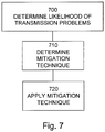
- FIG. 7 shows a general method according to the teachings herein.
- the first radio frequency communication device 320 determines 700 if a power imbalance (due to simultaneous transmission to the network node 310 and reception from the peer device or vice versa) will be likely to cause or is currently causing a transmission or reception problem on one or both links. If the radio frequency communication device 320 determines that such a problem can occur in the forthcoming communication or is occurring in the current communication, then the radio frequency communication device 320 determines 710 an appropriate solution or mitigation technique.
- the radio frequency communication device 320 may be configured to determine that the mitigation technique should involve prioritizing transmissions/receptions between D2D links (D2D TX/RX) and network links (NW TX/RX).
- the radio frequency communication device 320 may be configured to determine that the mitigation technique should involve directly reducing a transmission power level. Also, other mitigation techniques are plausible. As a mitigation technique has been determined, the radio frequency communication device 320 then applies 720 the selected solution or mitigation technique during a subsequent data communication period (for example during a next subframe or over certain time period).
- the radio frequency communication device 320 may be configured to apply one or more such mitigation techniques autonomously, that is by its own accord. Additionally or alternatively, the radio frequency communication device 320 may be configured to apply one or more such mitigation techniques based on pre-defined rules. Additionally or alternatively, the radio frequency communication device 320 may be configured to receive a configuration from the network node 310 and to apply one or more such mitigation techniques based on a received configuration. Combinations of how the radio frequency communication device 320 applies the mitigation techniques are of course possible. The radio frequency communication device 320 may also be configured to report any mitigation technique to the network node 310 or the second radio frequency communication device 325 to enable them to adapt their transmissions accordingly.
- a radio frequency communication device 320 is connected 800 to a network node 310 as well as being in communication with a second radio frequency communication device 325 over a D2D link.
- the same frequency band (UL resources, UL band, DL resources, DL band) are used for network (cellular) communication and D2D communication.
- the D2D (time/frequency) resources may be pre-allocated for a time period by a network node 310 controlling the first radio frequency communication device 320.
- the radio frequency communication device 320 also receives scheduling grants from the network node 310, giving an indication that an UL transmission to the network node 310 is needed.
- the UL transmission can be a data channel (e.g. PUSCH in case of LTE) or a control channel (e.g. PUCCH in case of LTE).
- the radio frequency communication device 320 determines that the radio frequency communication device 320 is scheduled for a D2D reception and a network (cellular) transmission in the same sub frame, however in different frequency resources 810. The detection may be done by determining a request, via a scheduling grant from the network node 310, to send UL information in a sub frame in which the radio frequency communication device 320 should receive from the second radio frequency communication device 325 in the D2D communication.
- a first set of resources is allocated to the network (cellular) transmission and a second set of resources is allocated to D2D reception/communication, possibly by the second radio frequency communication device 325.
- a controller in the radio frequency communication device 320 determines 820 whether there will be any problem associated with the simultaneous transmission and reception.
- the controller in the radio frequency communication device 320 determines 820 whether there will be any problem associated with the simultaneous transmission and reception by determining if there is a likelihood for such a problem.
- the likelihood for a problem may be based on a current signal environment, which in turn may be defined by current noise or interference levels. For example, if there has been a trend in rising noise levels, the controller may be determined that there is a likelihood that problems will occur in the next transmissions/receptions and may thus, proactively, determine that there is a problem.
- the transmission power may be larger than a threshold indicating that there is a risk for transmission leakage problem, as described above. If no problem is detected, then the radio frequency communication device 320 proceeds with the simultaneous communication 830.
- the radio frequency communication device 320 determines one or more mitigation techniques to solve the problem 840.
- the radio frequency communication device 320 may also be configured to decide not to perform simultaneous network (cellular) transmission and D2D reception or vice versa until the detected problem does no longer exist or until a certain time period has expired.
- the selected mitigation technique(s) is then applied by the radio frequency communication device 320 or possibly communicated to the network node 310 and/or the second radio frequency communication device 325 for application.
- the mitigation technique applied by the radio frequency communication device 320 comprises at least one of the prioritization between reception on D2D or network (cellular) transmission, restricted network (cellular) transmission or adjustment of network (cellular) transmission power (alternatively D2D transmission power).
- a first general mitigation technique is to prioritize between D2D reception and network (cellular) transmission.
- Some examples of prioritization rules are to prioritize network (cellular) transmission over D2D reception, prioritize network (cellular) control data communication (such as RRM/RRC) over D2D reception, prioritize D2D reception over transmitting a scheduling request, prioritize D2D control data reception over network (cellular) data communication, prioritize based on a number of HARQ transmission (i.e. retransmission n higher priority than m if n>m). This means reception of retransmission n in D2D link has higher priority than transmission of retransmission m in the UL. Also the opposite holds, i.e.
- a mitigation technique may be to prioritize signal measurements for the reception over a network (cellular) transmission. Similar prioritization rules could also be applied to the case with simultaneous cellular reception and D2D transmission.
- a second general mitigation technique is to adapt or adjust the transmission power.
- the radio frequency communication device 320 is configured to adjust (lower) the transmission power level on the UL transmission such that the inband emission will not interfere with the D2D reception.
- the radio frequency communication device 320 may be configured to determine whether the inband emission will interfere or not by having initial knowledge of the inband emission level, either based on a predefined specification requirement (i.e. -30 dBc relative transmitted power spectral density (dBm/Hz)) or based on a measured inband emission level (either measured in lab, or based on real time measurements).
- the radio frequency communication device 320 determines whether it is possible to lower the transmission level (and still making it possible for the network node 310 to successfully receive the information) so that reception is possible. This approach might be applicable in case of a relative high RX level (say -60 dBm) and low transmission level (say -30 dBm).
- the radio frequency communication device 320 is configured to adapt the network (cellular) transmission power level by transmitting an adapted transmission power level to said network node 310 for adapted transmission to said radio frequency communication device 320 from said network node 310 thereby enabling a mitigation of a transmission power leakage even when not actively transmitting.
- the radio frequency communication device 320 is configured to a D2D transmission power level by transmitting an adapted transmission power level to said second radio frequency communication device 325 for adapted transmission to said radio frequency communication device 320 from said second radio frequency communication device 325thereby enabling a mitigation of a transmission power leakage even when not actively transmitting
- a third general mitigation technique is to restrict the transmission.
- the radio frequency communication device 320 is configured to only transmit a fraction of the network (cellular) communication information. For instance, if the network node 310 sends uplink grant for a data channel transmission (e.g. PUSCH) which includes uplink feedback information (e.g. HARQ (Hybrid Automatic Repeat request), PMI (Precoding Matrix Indicator), CQI (Channel Quality Information) information etc), the radio frequency communication device 320 may instead transmit a control channel (e.g. PUCCH) including only the uplink feedback information (e.g. HARQ and CQI information etc) or even selected uplink feedback information (e.g. only HARQ).
- a control channel e.g. PUCCH
- the radio frequency communication device 320 may only transmit a subset of the allocated resource blocks to the network node 310. For example, the radio frequency communication device 320 only transmits on 5 RBs instead of 10 RBs. Similar to the second general mitigation technique above this approach is suitable if reception signal level is high and the (original) transmission signal level is low.
- a fourth general mitigation technique is to discontinuously transmit on the network (cellular) link.
- the radio frequency communication device 320 detects the problem and in response thereto starts to transmit to the network node310 over a network (cellular) link infrequently according to a transmission pattern, which is termed here as discontinuous signal transmission pattern (e.g. transmitting during one (ON) one subframe out of N consecutive available subframes; N can for example be 10 or 20 subframes).
- the transmission pattern therefore comprises ON and OFF time periods.
- the radio frequency communication device 320 does not transmit to the network node 310.
- the radio frequency communication device 320 receives signals over the D2D link as usual.
- the radio frequency communication device 320 either does not receive from the second radio frequency communication device 325 on a D2D link or the second radio frequency communication device 325 transmits using a more robust MCS (e.g. QPSK and/or low code rate like 1/3) and/or by using higher output or transmission power. In this manner the radio frequency communication device 320 is also able to simultaneously receive the signals from the second radio frequency communication device 325 over the D2D link while transmitting on the network (cellular) transmission link during the transmit pattern's ON time period.
- the pattern may be pre-defined or it may be configurable by the network node 310 as explained above.
- a fifth general mitigation technique is to discontinuously receive over the D2D reception link.
- the radio frequency communication device 320 detects the problem and in response thereto starts to receive on the D2D reception link from the second radio frequency communication device 325 with which it is involved in D2D communication within a discontinuous reception mode. For example, during one subframe time period out of K consecutives available subframes (e.g. K can be 10 or 20 subframes) the radio frequency communication device 320 is receiving.
- the receive pattern therefore comprises of ON and OFF time periods. During an OFF time period, the radio frequency communication device 320 does not receive from the second radio frequency communication device 325 over the D2D reception link, but transmits to the network node 310 over the network (cellular) transmission link.
- the radio frequency communication device 320 receives signals from the second radio frequency communication device 325 over the D2D reception link. Also during an ON time period, the radio frequency communication device 320 does not transmit to the network node 310 over the network (cellular) transmission link or the radio frequency communication device 320 transmits using low output or transmission power. The transmission power may be below a threshold to avoid degradation of signal quality. In this manner the radio frequency communication device 320 is also able to simultaneously receive the signals from the second radio frequency communication device 325 over the D2D reception link while transmitting over the network (cellular) transmission also during the receiver pattern's ON time period.
- the second radio frequency communication device 325 may also be informed when the first radio frequency communication device 320 starts the pattern by the first radio frequency communication device 320 or by the network node 310.
- the time when the radio frequency communication device 320 starts the pattern may also be based on a pre-defined rule (e.g. first device uses pre-defined pattern when signal quality is below a threshold).
- the second radio frequency communication device 325 also starts to transmit to the first radio frequency communication device 320 using D2D communication only during an ON time period.
- the pattern may be pre-defined or configurable by the network node 310 as explained above.
- a sixth general mitigation technique is to adapt the receiver.
- the radio frequency communication device 320 detects the problem, and in response thereto, adapts one or more parameters related to its receiver, the receiver being part of the radio frequency communication interface 130, to enhance signal reception quality.
- the radio frequency communication device 320 starts to use an enhanced receiver (also being part of the radio frequency communication interface 130) for receiving signals from the second radio frequency communication device 325 over the D2D reception link.
- An enhanced receiver is capable of mitigating the interference more effectively than the baseline receiver.
- An enhanced receiver herein refer to a receiver that is capable of mitigating interference caused by the leakage due to signals transmitted on the network (cellular) transmission link to the network node 310.
- enhanced receivers are successive interference cancellation (SIC) where the transmission emission is estimated and subtracted (this is possible since the device knows the signal to be transmitted, and may also have a mathematical model of the PA (and other) non-linearities that generate he inband emission), or maximum likelihood (ML) receivers etc.
- SIC successive interference cancellation
- ML maximum likelihood
- Another example of adaptation of the receiver is to switch the receiver link bandwidth to a narrow band receiver link.
- the bandwidth is adapted to the D2D allocation bandwidth (for instance 6 PRBs) to filter out a possible strong transmission signal on adjacent PRBs.
- An adjustment of the local oscillator may also be performed.
- Such an adaptation of the local oscillator may be performed through switching the center frequency from the center of the system bandwidth (that might be 20 MHz, 100 PRBs) to the center of the D2D PRB allocation. This approach is especially suitable if the inband emission is of less problem, but the receiver signal dynamics (for instance ADC dynamic) is the limiting factor.
- the radio frequency communication device 320 is configured to revert to the baseline receiver (being part of the radio frequency communication interface 130) when the problem is alleviated or reception quality of the D2D RX is within an acceptable limit, such as when SINR at the receiver of the radio frequency communication device 320 is above, say, -3 dB.
- the enhanced receiver consumes more power, involves more processing and implementation complexity compared to the baseline receiver. The enhanced receiver is therefore used only when the problem due to simultaneous D2D reception and NW transmission (or vice versa) persists.
- the interference mitigation performed by the radio frequency communication device 320 herein means reducing, minimizing, eliminating, cancelling, avoiding, rejecting etc., interference caused by the leakage due to the signals sent on the network (cellular) transmission link of the radio frequency communication device 320.
- the radio frequency communication device 320 is configured to apply any combination of the alternatives described above.
- the prioritization rule may be determined in several different ways.
- the prioritization rule is generated by the network node 310 and thus also configured by the network node 310.
- the network node 310 may use one or more conditions to generate the rule and configure the radio frequency communication device 320 to apply the rule(s). For example the network node 310 may receive signal quality measurement performed by the radio frequency communication device 320 on the signal received over the D2D reception link from a second radio frequency communication device 325 with which the first radio frequency communication device 320 is involved in D2D communication with. If the signal quality is below a threshold (e.g. SINR or SNR is below, say, -3 dB), then the network node 310 may configure the radio frequency communication device 320 to use a particular mitigation technique or plurality of techniques. For example, the radio frequency communication device 320 may be configured to perform an adjustment of the transmission power if both D2D reception and network (cellular) transmission is required to operate all the time simultaneously.
- a threshold e.g. SINR or SNR is below, say, -3 dB
- the rule is defined by the standard (for instance 3GPP in case of LTE) in the form of a pre-determined rule.
- one or more pre-defined rules are also associated with one or more triggering conditions.
- the triggering conditions enable the radio frequency communication devices 320 and also the network node 310 to determine and apply the pre-defined rules. For example, if the signal quality on the D2D reception link is below a threshold (e.g. -1 dB), then the radio frequency communication device 320 can only trigger discontinuous transmission on the network (cellular) transmission link. If the signal quality falls further below -3 dB then the radio frequency communication device 320 can also trigger discontinuous reception on the D2D reception link.
- a threshold e.g. -1 dB
- the radio frequency communication device 320 is enabled to turn off both schemes (discontinuous transmission and discontinuous reception) and revert to normal operation i.e. perform D2D reception and network (cellular) transmission simultaneously during the assigned resources.
- the radio frequency communication device 320 informs the network node 310 and/or the second radio frequency communication device 325 about the currently applied rule(s), after having selected a rule. This enables the network node 310 and the second radio frequency communication device 325 to determine the impact on its own reception and transmission of signals respectively.
- the network node 310 and the second radio frequency communication device 325 can, in turn, apply a suitable mitigation technique to avoid performance degradation.
- the network node 310 may use a more robust receiver that can receive a signal whose signal level is below a threshold or whose received signal quality is below a threshold.
- the prioritization rule is determined by the network node 310 based on a negotiation between the network node 310, and the radio frequency communication devices 320, 325 involved in the D2D communication.
- the network node 310 may configure the radio frequency communication device 320 with the rule and the associated parameters e.g. threshold for triggering the rule.
- the radio frequency communication device 320 informs the network node 310 upon detecting the problem. In response the network node 310 configures the radio frequency communication device 320 with the appropriate rule and associated parameters.
- the prioritization rule may also be determined based on radio frequency communication device capabilities (e.g. type of radio access capability to operate or handle simultaneous signal transmission on network (cellular) transmission link and signal reception on D2D reception link may be reported by the radio frequency communication device 320 to the network node 310.
- the capability may also be signaled by the radio frequency communication device 320 to the second radio frequency communication device 325 capable of D2D communication.
- the capability information may also comprise specific mitigation techniques which the radio frequency communication device 320 is capable to apply in order to handle the simultaneous signal transmission over the network (cellular) transmission link and signal reception over the D2D reception link.
- a radio frequency communication device 320 may indicate that it supports all pre-defined mitigation techniques.
- a device may indicate that it is capable of applying only (a) specific mitigation technique(s), such as prioritization between D2D reception and network (cellular) transmission and transmission power adjustment.
- the capability information may also indicate that the capability (or associated information) is applicable to all frequency bands or to specific frequency bands (e.g. E-UTRA band 1, E-UTRA band 7, all E-UTRA bands below 1 GHz etc).
- the radio frequency communication device 320 may signal the capability to any suitable network node 310 such as a serving NW node, core network node, positioning node etc.
- the network node 310 uses that information to determine the priority rule used for that radio frequency communication device 320 to handle and mitigate the simultaneous D2D reception and network (cellular) transmission problem (or vice versa).
- one radio frequency communication device may have less inband emission and hence may be configured with restricted transmission possibilities while a low cost radio frequency communication device with large inband emission may be configured to prioritize transmission or reception.
- the network node 310 may also signal or forward the obtained device capability information to another network node, For example, a serving eNode B may signal this to a neighboring eNode B over X2 interface.
- the capability information may also be stored by the network node 310.
- the network node 310 may then use the stored (historical) data for applying or selecting the most suitable rule for the corresponding radio frequency communication device at a future time.
- the prioritization may also be determined in a combination of the above manners, including one, several or all of the network node 310, the radio frequency communication device 230 and a communication standard.
- the radio frequency communication device and/or the network node 310 may also be configured to update the prioritization rule dynamically.
- the network node 310 may update the priority rule each mode selection period (which may be in the order of 200-500 ms). Alternatively or additionally, the network node 310 may update the priority rule upon a detected event or condition.
- the event or condition and corresponding thresholds can be pre-defined or implementation specific.
- a measurement report e.g. signal quality (e.g. RSRQ), signal strength (e.g. RSRP), SINR, SNR, BLER, BER etc
- the network node 310 receives such reports from the radio frequency communication device. For example in one event it is above a first threshold. In a second event it is below a second threshold. The event may also be triggered by a measurement report performed by a second radio frequency communication device 325 connected to the network node 310.
- a measurement report e.g. signal quality, signal strength, SINR, SNR, BLER, BER etc
- the network node 310 e.g. on signal transmitted over the network (cellular) transmission link
- a certain threshold For example in one event it is above a first threshold. In a second event it is below a second threshold.
- the event may also be triggered by a measurement report performed by the network node 310 on signal transmitted by a second radio frequency communication device 325 over its network (cellular) transmission link.
- Another example of such an event is when the cell load in a cell being served by the network node 310 changes, such as when the transmitted power differs from a threshold, the total resource usage (e.g. percentage of usage of UL and/or DL resource blocks) differs from a threshold, the number of users in a cell differs from a threshold, the number of users with D2D communication using network (cellular) transmission, and/or the number of users with simultaneous D2D reception and network (cellular) transmission etc.
- the network node 310 initiates one or more rules or change their priority order. If the upload cell load is above a threshold (i.e. based on one or more criteria such as UL resource usage etc), then the network node 310 may increase the priority of the rule such that both transmission power adjustment and discontinuous reception at the D2D reception link are of highest priority.
- Another example of such an event is when a change of a state in any of the involved devices is detected.
- state changes are a cell change, a handover, a RRC (Radio Resource Control) connection re-establishment, a reconfiguration of connection, any of configuration, reconfiguration, activation or deactivation of one or more secondary cells (SCell) in CA, changing RRC states (e.g. from IDLE state to RRC connected or vice versa etc), configuration or reconfiguration or activation or deactivation of radio links involved in CoMP (Coordinated Multipoint transmission), power state in the device from ON to OFF (or vice versa).
- RRC Radio Resource Control
- Another example of such an event is when a change in a network node status is detected.
- states are bi-states like a high load in the served cell, low load in the served cell, tri-state like high load, medium load or low load in the served cell, or power state of the network node 310 changing from ON state to OFF state due to power saving, maintenance activity etc.
- the network node 310 may use any combination of the events to update the priority of the rules. For example the network node 310 may only change the current priority order of the rules provided all events are detected.
- the radio frequency communication device 320 may also be configured to report the selected mitigation technique (taken action) to the network node 310 or the second radio frequency communication device 325.
- the report is made to the radio frequency communication device 320 whose communication was abandoned/restricted, but not to the other node.
- the report may be done in a sub frame where the communication is possible with the network node 310 or radio frequency communication device to receive the report.
- a radio frequency communication device 320 is connected to a network node 310 and is also involved in communication with another radio frequency communication device 325 via network (cellular) assisted D2D communication 800 using a same system frequency bandwidth as the NW communication.
- the radio frequency communication device 320 determines a need for simultaneous D2D reception and D2D Transmission 810 according to above.
- the radio frequency communication device 320 determines whether there is any problem associated with simultaneous transmission and reception 820. If not, the transmission/reception is made according to scheduled principles 830. If a problem is detected, the radio frequency communication device 320 (or the network node 310) determines a solution to solve the problem according to above 840.
- the radio frequency communication device 320 proceeds with the communication according to the selected mitigation technique 850.
- the radio frequency communication device 320 reports 860 the selected mitigation technique at a later stage to the network node 310 or the radio frequency communication device 320 reports 870 the selected mitigation technique at a later stage to the second radio frequency communication device.
- the embodiments above have been described in terms of assuming simultaneous transmission and reception in the same sub frame, but the embodiments are also applicable when the network (cellular) communication and D2D communication is not synchronized. For instance, a D2D sub frame may only partly overlap a sub frame for network (cellular) communication. Hence, the embodiments are also applicable to simultaneous transmission and reception over a subset of OFDM symbols in a sub frame.
- the disclosed embodiment provides consistent strategies for a radio frequency communication device handling scenarios involving simultaneous transmission and reception. Furthermore, overall robustness in the communication system is also provided.
- the denominator network node may be an eNode B, node B, Base Station, wireless access point (AP), base station controller, relay, donor node controlling relay, base transceiver station (BTS), transmission points, transmission nodes, RRU, RRH, nodes in distributed antenna system (DAS) etc.
- a radio frequency communication device may be an UE, sensor, lap top modem, smart phone, machine type (MTC) device, PDA, iPAD, Tablet, smart phone, laptop embedded equipped (LEE), laptop mounted equipment (LME), USB dongles etc.
Claims (8)
- Funkfrequenzkommunikationsvorrichtung (100, 320), die eine Funkfrequenzkommunikationsschnittstelle (130) und eine Steuerung (110) umfasst, wobei die Steuerung (110) zu Folgendem ausgelegt ist:Aufbauen einer Netzwerkkommunikation mit einem Netzwerkknoten (200, 310) und Aufbauen einer Vorrichtung-zu-Vorrichtung-Kommunikation einer zweiten Funkfrequenzkommunikationsvorrichtung (325) via die Funkfrequenzkommunikationsschnittstelle (130);Bestimmen, ob eine gleichzeitige Kommunikation durchgeführt werden muss, die eine Netzwerkübertragung über die Netzwerkkommunikation mit dem Netzwerkknoten (200, 310) und einen D2D-Empfang über die Vorrichtung-zu-Vorrichtung-Kommunikation mit der zweiten Funkfrequenzkommunikationsvorrichtung (325) oder einen Netzwerkempfang über die Netzwerkkommunikation mit dem Netzwerkknoten (200, 310) und eine D2D-Übertragung über die Vorrichtung-zu-Vorrichtung-Kommunikation mit der zweiten Funkfrequenzkommunikationsvorrichtung (325) umfasst,Bestimmen, ob das Auftreten eines Übertragungsproblems, das die gleichzeitige Kommunikation betrifft, wahrscheinlich ist; und wenn ja, Bestimmen einer Minderungstechnik zum Mindern des erwarteten Übertragungsproblems; und Durchführen der Netzwerkübertragung und des D2D-Empfangs oder des Netzwerkempfangs und der D2D-Übertragung gemäß der Minderungstechnik,wobei die Steuerung (110) dazu ausgelegt ist zu bestimmen, dass das Auftreten eines Übertragungsproblems bei einer künftigen Übertragung bzw. einem künftigen Empfang wahrscheinlich ist, wenn die Steuerung einen Trend bei ansteigenden Rauschpegeln detektiert, und durch Erhöhen oder Verringern von einem eines Netzwerkübertragungsleistungsniveaus oder eines D2D-Übertragungsleistungsniveaus ein Übertragungsleistungsniveau gemäß der Minderungstechnik proaktiv anzupassen, derart, dass eine Differenz zwischen einem Empfangsleistungsniveau und einem Übertragungsleistungsniveau unter einem Schwellwertniveau liegt.
- Funkfrequenzkommunikationsvorrichtung (100, 320) nach Anspruch 1, wobei die Steuerung (110) dazu ausgelegt ist, das Übertragungsleistungsniveau durch Folgendes anzupassen: Übertragen eines angepassten Übertragungsleistungsniveaus zum Netzwerkknoten (200, 310) für eine angepasste Übertragung vom Netzwerkknoten (200, 310) zur Funkfrequenzkommunikationsvorrichtung (100, 320) oder Übertragen eines angepassten Übertragungsleistungsniveaus zur zweiten Funkfrequenzkommunikationsvorrichtung (325) für eine angepasste Übertragung von der Funkfrequenzkommunikationsvorrichtung (325) zur zweiten Funkfrequenzkommunikationsvorrichtung (100, 320).
- Funkfrequenzkommunikationsvorrichtung (100, 320) nach einem der vorhergehenden Ansprüche, wobei die Steuerung (110) dazu ausgelegt ist, durch Einschränken der zu übertragenden Informationen die Übertragung bei einem der Netzwerkübertragungsleistung oder der D2D-Übertragungsleistung einzuschränken.
- Funkfrequenzkommunikationsvorrichtung (100, 320) nach einem der vorhergehenden Ansprüche, wobei die Steuerung (110) dazu ausgelegt ist, eines der Netzwerkübertragung und des D2D-Empfangs oder des Netzwerkempfangs und der D2D-Übertragung zu priorisieren und nur die priorisierte Kommunikation gemäß der Minderungstechnik durchzuführen.
- Funkfrequenzkommunikationsvorrichtung (100, 320) nach Anspruch 4, wobei die Steuerung (110) dazu ausgelegt ist, eine Übertragung eines Signals oder eines physischen Kanals, das bzw. der Steuerinformationen transportiert, gemäß der Minderungstechnik zu priorisieren.
- Funkfrequenzkommunikationsvorrichtung (100, 320) nach einem der vorhergehenden Ansprüche, wobei die Minderungstechnik auf vordefinierten Regeln basiert, die in einem Speicher (140) gespeichert sind, der in der Funkfrequenzkommunikationsvorrichtung (100, 320) umfasst ist; und wobei die vordefinierten Regeln mindestens eines von einem Zustand der Funkfrequenzkommunikationsvorrichtung (100, 320) und einem Auslöseereignis betreffen.
- Verfahren zur Verwendung in einer Funkfrequenzkommunikationsvorrichtung (100, 320), die eine Funkfrequenzkommunikationsschnittstelle (130) und eine Steuerung (110) umfasst, wobei das Verfahren Folgendes umfasst:Aufbauen einer Netzwerkkommunikation mit einem Netzwerkknoten (200, 310);Aufbauen einer Vorrichtung-zu-Vorrichtung-Kommunikation einer zweiten Funkfrequenzkommunikationsvorrichtung (325) via die Funkfrequenzkommunikationsschnittstelle (130);Bestimmen, ob eine gleichzeitige Kommunikation durchgeführt werden muss, die eine Netzwerkübertragung über die Netzwerkkommunikation mit dem Netzwerkknoten (200, 310) und einen D2D-Empfang über die Vorrichtung-zu-Vorrichtung-Kommunikation mit der zweiten Funkfrequenzkommunikationsvorrichtung (325) oder einen Netzwerkempfang über die Netzwerkkommunikation mit dem Netzwerkknoten (200, 310) und eine D2D-Übertragung über die Vorrichtung-zu-Vorrichtung-Kommunikation mit der zweiten Funkfrequenzkommunikationsvorrichtung (325) umfasst,Bestimmen, ob das Auftreten eines Übertragungsproblems, das die gleichzeitige Kommunikation betrifft, wahrscheinlich ist; und wenn ja, Bestimmen einer Minderungstechnik zum Mindern des Übertragungsproblems; undDurchführen der Netzwerkübertragung und des D2D-Empfangs oder des Netzwerkempfangs und der D2D-Übertragung gemäß der Minderungstechnik,wobei das Bestimmen, ob das Auftreten eines Übertragungsproblems bei einer künftigen Übertragung bzw. einem künftigen Empfang wahrscheinlich ist, auf Basis der Detektion eines Trends bei ansteigenden Rauschpegeln und proaktives Anpassen eines Übertragungsleistungsniveaus gemäß der Minderungstechnik durch Erhöhen oder Verringern von einem eines Netzwerkübertragungsleistungsniveaus und eines D2D-Übertragungsleistungsniveaus, derart, dass eine Differenz zwischen einem Empfangsleistungsniveau und einem Übertragungsleistungsniveau unter einem Schwellwertniveau liegt.
- Computerlesbares Speichermedium (40), das mit Anweisungen (41) codiert ist, die, wenn sie in einen Prozessor einer Funkfrequenzkommunikationsvorrichtung (320) geladen und von demselben ausgeführt werden, bewirken, dass das Verfahren nach Anspruch 7 durchgeführt wird.
Applications Claiming Priority (2)
| Application Number | Priority Date | Filing Date | Title |
|---|---|---|---|
| US201361821107P | 2013-05-08 | 2013-05-08 | |
| PCT/EP2013/075400 WO2014180517A1 (en) | 2013-05-08 | 2013-12-03 | Improved handling of simultaneous network communication transmission and d2d communication reception or simultaneous network communication reception and d2d communication transmission |
Publications (2)
| Publication Number | Publication Date |
|---|---|
| EP2995156A1 EP2995156A1 (de) | 2016-03-16 |
| EP2995156B1 true EP2995156B1 (de) | 2020-12-02 |
Family
ID=51866831
Family Applications (1)
| Application Number | Title | Priority Date | Filing Date |
|---|---|---|---|
| EP13814060.3A Active EP2995156B1 (de) | 2013-05-08 | 2013-12-03 | Verbesserte handhabung einer netzwerkkommunikationsübertragung mit gleichzeitigem d2d-kommunikationsempfangs oder eines netzwerkkommunikationsempfangs mit gleichzeitiger d2d-kommunikationsübertragung |
Country Status (3)
| Country | Link |
|---|---|
| US (1) | US10098129B2 (de) |
| EP (1) | EP2995156B1 (de) |
| WO (1) | WO2014180517A1 (de) |
Families Citing this family (33)
| Publication number | Priority date | Publication date | Assignee | Title |
|---|---|---|---|---|
| WO2014180518A1 (en) * | 2013-05-08 | 2014-11-13 | Telefonaktiebolaget L M Ericsson (Publ) | Improved handling of simultaneous network communication transmission and d2d communication transmission |
| WO2014180519A1 (en) | 2013-05-08 | 2014-11-13 | Telefonaktiebolaget L M Ericsson (Publ) | Improved selection of scheduling policy for network communications links and d2d communications links |
| EP2995156B1 (de) | 2013-05-08 | 2020-12-02 | Guangdong Oppo Mobile Telecommunications Corp., Ltd. | Verbesserte handhabung einer netzwerkkommunikationsübertragung mit gleichzeitigem d2d-kommunikationsempfangs oder eines netzwerkkommunikationsempfangs mit gleichzeitiger d2d-kommunikationsübertragung |
| JP6108980B2 (ja) | 2013-06-27 | 2017-04-05 | 京セラ株式会社 | 移動通信システム及びユーザ端末 |
| US20150043446A1 (en) * | 2013-08-12 | 2015-02-12 | Qualcomm Incorporated | Method and apparatus for coexistence of device to device and lte wan communication using single communication chain |
| WO2015147608A1 (ko) * | 2014-03-28 | 2015-10-01 | 엘지전자 주식회사 | 단말 간 통신을 지원하는 무선 통신 시스템에서 신호를 송수신하는 방법 및 이를 위한 장치 |
| US10070455B2 (en) * | 2014-03-28 | 2018-09-04 | Lg Electronics Inc. | Method and apparatus for prioritizing D2D transmission and D2D reception in wireless communication system |
| JP2017513392A (ja) * | 2014-03-28 | 2017-05-25 | エルジー エレクトロニクス インコーポレイティド | 無線通信システムにおける端末により実行されるd2d動作方法及びその方法を利用する端末 |
| US20170048647A1 (en) * | 2014-05-06 | 2017-02-16 | Lg Electronics Inc. | Method for device-to-device (d2d) operation executed by terminal in wireless communication system and terminal using the method |
| US9485725B2 (en) * | 2014-06-25 | 2016-11-01 | Qatar University Qstp-B | Methods and system for dynamically switching off/on of base stations |
| CN105594165B (zh) * | 2014-09-05 | 2019-07-09 | 华为技术有限公司 | 一种分流策略协商方法及装置 |
| WO2016172877A1 (zh) * | 2015-04-29 | 2016-11-03 | 华为技术有限公司 | 一种小区功率共享和调整方法和基站 |
| WO2016175639A1 (ko) * | 2015-04-30 | 2016-11-03 | 엘지전자 주식회사 | 무선 통신 시스템에서 단말에 의해 수행되는 d2d 동작 방법 및 상기 방법을 이용하는 단말 |
| CN106304373A (zh) * | 2015-05-15 | 2017-01-04 | 电信科学技术研究院 | 一种资源协调的方法和装置 |
| EP3308488B1 (de) * | 2015-07-06 | 2020-01-01 | Huawei Technologies Co., Ltd. | Rahmenstruktur, kommunikationsvorrichtungen und verfahren zur kommunikation |
| CN108029148B (zh) * | 2015-07-23 | 2022-04-01 | 苹果公司 | 移动性中继方法和装置 |
| US10244482B2 (en) * | 2015-08-21 | 2019-03-26 | Lg Electronics Inc. | Method for transmitting or receiving V2X signal in wireless communication system and device for performing same |
| CN105101381B (zh) * | 2015-08-28 | 2018-05-15 | 东南大学 | 多信道蜂窝用户情况下的d2d功率分配快速优化方法 |
| CN106658352B (zh) * | 2015-11-02 | 2019-03-22 | 中兴通讯股份有限公司 | 车联网v2x业务的转发方法及装置 |
| US20190068342A1 (en) * | 2016-01-29 | 2019-02-28 | Nokia Solutions And Networks Oy | Communication efficiency |
| US10728727B2 (en) * | 2016-03-04 | 2020-07-28 | Lenovo Enterprise Solutions (Singapore) Pte. Ltd. | Systems and methods for reducing interference in wireless communication among computing devices |
| US10129885B2 (en) | 2016-03-09 | 2018-11-13 | Seiko Epson Corporation | Wireless communication apparatus and wireless communication method |
| US20170272955A1 (en) * | 2016-03-18 | 2017-09-21 | Qualcomm Incorporated | Communication pattern detection for unlicensed radio frequency spectrum bands |
| US10045354B2 (en) * | 2016-03-24 | 2018-08-07 | Starkey Laboratories, Inc. | Adaptive channel mapping for wireless communications |
| CN109891987B (zh) * | 2016-11-04 | 2022-06-24 | 瑞典爱立信有限公司 | 用于无线通信系统中的传输调度的方法和装置 |
| EP3528566B1 (de) * | 2016-11-04 | 2022-05-25 | Huawei Technologies Co., Ltd. | Drahtlosnetzwerkdatenübertragungsverfahren, -vorrichtung und -system |
| CN107666700A (zh) * | 2017-08-30 | 2018-02-06 | 深圳大学 | 添加d2d通信的分布式天线系统中功率分配方法及装置 |
| CN107979826A (zh) * | 2017-11-28 | 2018-05-01 | 深圳大学 | 复用模式下含d2d通信的das中功率分配方法及装置 |
| EP3723305A4 (de) | 2017-12-29 | 2020-12-23 | Huawei Technologies Co., Ltd. | Verfahren und vorrichtung zur detektion von funkfrequenzkanalverbindungen |
| EP3794890A1 (de) | 2018-05-15 | 2021-03-24 | Telefonaktiebolaget LM Ericsson (publ) | Verfahren und netzknoten zur behandlung der übertragung von lte- oder nr-signalen und nb-iot-signalen an drahtlose kommunikationsgeräte |
| US11388733B2 (en) * | 2018-12-20 | 2022-07-12 | Asustek Computer Inc. | Method and apparatus for handling sidelink feedback collision in a wireless communication system |
| KR20210011277A (ko) * | 2019-07-22 | 2021-02-01 | 삼성전자주식회사 | 채널 피드백에 기초한 멀티캐스트 전송을 위한 방법 및 장치 |
| US11856638B2 (en) * | 2020-02-11 | 2023-12-26 | Qualcomm Incorporated | Discontinuous reception configuration and sidelink operation with mode-1 and mode-2 scheduling |
Citations (4)
| Publication number | Priority date | Publication date | Assignee | Title |
|---|---|---|---|---|
| US20100093364A1 (en) * | 2008-09-12 | 2010-04-15 | Nokia Corporation | Method and apparatus for providing interference measurements for device-to-device communication |
| US20110275382A1 (en) * | 2010-05-06 | 2011-11-10 | Sami-Jukka Hakola | Measurements and Fast Power Adjustments in D2D Communications |
| US20120120892A1 (en) * | 2010-11-16 | 2012-05-17 | Interdigital Patent Holdings, Inc. | Method and apparatus for wireless direct link operation |
| US20130012191A1 (en) * | 2010-03-25 | 2013-01-10 | Nokia Corporation | Method and Apparatus for Providing Machine-to-Machine Communication in a Wireless Network |
Family Cites Families (43)
| Publication number | Priority date | Publication date | Assignee | Title |
|---|---|---|---|---|
| JP3577754B2 (ja) * | 1994-09-09 | 2004-10-13 | ソニー株式会社 | 通信方法及び装置 |
| JP3165125B2 (ja) | 1998-12-24 | 2001-05-14 | 日本電気株式会社 | 無線通信における多重アクセス方法 |
| SE517019C2 (sv) * | 1999-08-27 | 2002-04-02 | Ericsson Telefon Ab L M | Ett förfarande och en anordning för att förbättra kapaciteten hos en GSM basstation |
| US6707808B1 (en) | 2000-03-17 | 2004-03-16 | Telefonaktiebolaget Lm Ericsson (Publ) | Method and system for fast access to an uplink channel in a mobile communication network |
| JP2002208923A (ja) | 2001-01-11 | 2002-07-26 | Oki Electric Ind Co Ltd | 間欠信号の暗号化伝送システム |
| US7295528B2 (en) | 2003-03-12 | 2007-11-13 | Broadcom Corporation | Peer to peer wireless communication conflict resolution |
| US20090318087A1 (en) | 2006-02-20 | 2009-12-24 | Mattila Heikki O | Method and Device for Preventing Interference at a Radio Receiver Device Caused by Several Radio Transmitter Devices |
| US8452317B2 (en) | 2006-09-15 | 2013-05-28 | Qualcomm Incorporated | Methods and apparatus related to power control and/or interference management in a mixed wireless communications system supporting WAN signaling and peer to peer signaling |
| US9264907B2 (en) | 2007-07-10 | 2016-02-16 | Qualcomm Incorporated | Method and apparatus for interference management between networks sharing a frequency spectrum |
| EP2031921A1 (de) | 2007-08-14 | 2009-03-04 | Alcatel Lucent | Vorrichtung und Verfahren zur Verwaltung von Kapazitätsinformationen eines mobilen Endgeräts |
| US9072060B2 (en) * | 2008-06-03 | 2015-06-30 | Nokia Technologies Oy | Method, apparatus and computer program for power control to mitigate interference |
| KR101296021B1 (ko) * | 2008-10-29 | 2013-08-12 | 노키아 코포레이션 | 무선 통신 시스템에서의 디바이스 대 디바이스 통신을 위한 동적 통신 자원 할당을 위한 장치 및 방법 |
| WO2010082888A1 (en) | 2009-01-14 | 2010-07-22 | Telefonaktiebolaget L M Ericsson (Publ) | Method and arrangement in a wireless communication system |
| CN102282901B (zh) | 2009-01-16 | 2015-06-17 | 诺基亚公司 | 在蜂窝网络中实现装置到装置通信 |
| US8879479B2 (en) | 2009-01-27 | 2014-11-04 | Motorola Solutions, Inc. | Reactive scheduling methods and apparatus to enable peer-to-peer communication links in a wireless OFDMA system |
| US8213360B2 (en) * | 2009-04-29 | 2012-07-03 | Nokia Corporation | Apparatus and method for flexible switching between device-to-device communication mode and cellular communication mode |
| WO2010125427A1 (en) * | 2009-04-30 | 2010-11-04 | Nokia Corporation | Method and apparatus for managing device-to-device interference |
| US20120250636A1 (en) | 2009-06-04 | 2012-10-04 | Nokia Corporation | Effective Labeling of Subframes Based on Device-to-Device Transmission in Cellular Downlink Spectrums |
| US8885507B2 (en) * | 2009-12-11 | 2014-11-11 | Nokia Corporation | Method, apparatus and computer program product for allocating resources in wireless communication network |
| US9198162B2 (en) | 2010-03-23 | 2015-11-24 | Nokia Solutions And Networks Oy | Resource allocation for direct terminal-to-terminal communication in a cellular system |
| US8811359B2 (en) * | 2010-04-15 | 2014-08-19 | Qualcomm Incorporated | Multiplexing of peer-to-peer (P2P) communication and wide area network (WAN) communication |
| US8934909B2 (en) | 2010-05-19 | 2015-01-13 | Nokia Corporation | Method and apparatus for providing communication offloading to unlicensed bands |
| US8447315B2 (en) | 2010-06-03 | 2013-05-21 | Nokia Corporation | Method and apparatus for facilitating device-to-device communication |
| US8838046B2 (en) | 2010-06-18 | 2014-09-16 | Mediatek Inc. | System and method of hybrid FDM/TDM coexistence interference avoidance |
| CN103229531B (zh) | 2010-07-30 | 2016-08-03 | 瑞典爱立信有限公司 | 无线通信中的干扰识别和减轻 |
| WO2012016378A1 (en) * | 2010-08-04 | 2012-02-09 | Nokia Corporation | A resolution method and apparatus for simultaneous transmission and receiving contention in a device-to-device cellular reuse system |
| WO2012034269A1 (en) | 2010-09-14 | 2012-03-22 | Nokia Corporation | Interference measurement and reporting for device-to-device communications in communication system |
| US9344997B2 (en) | 2010-10-13 | 2016-05-17 | Nokia Technologies Oy | Selection of communication mode |
| US9807633B2 (en) | 2010-11-05 | 2017-10-31 | Google Technology Holdings LLC | Configuring unscheduled periods to enable interference reduction in heterogeneous networks |
| EP2453711B1 (de) | 2010-11-15 | 2015-06-03 | NTT DoCoMo, Inc. | Verfahren zur Zuweisung von Frequenzteilbändern an eine Vielzahl von störenden Knoten in einem drahtlosen Kommunikationsnetzwerk, Steuerung für ein drahtloses Kommunikationsnetzwerk und drahtloses Kommunikationsnetzwerk |
| US8744458B2 (en) * | 2010-11-19 | 2014-06-03 | Nokia Corporation | Signaling mixed resource allocations for D2D communications |
| KR20120074251A (ko) | 2010-12-27 | 2012-07-05 | 한국전자통신연구원 | 단말간 직접 연결 통신 및 단말 릴레잉을 위한 디바이스 대 디바이스 링크의 harq 및 적응 전송 방법 |
| GB2491139B (en) * | 2011-05-24 | 2014-02-19 | Broadcom Corp | Channel access control |
| WO2013048296A1 (en) * | 2011-09-30 | 2013-04-04 | Telefonaktiebolaget L M Ericsson (Publ) | Method and arrangement for handling device-to-device communication in a wireless communications network |
| KR101868635B1 (ko) | 2011-10-28 | 2018-07-20 | 삼성전자주식회사 | 근거리 무선 통신 시스템에서의 신호 송수신 장치 및 방법 |
| KR20130063615A (ko) * | 2011-12-07 | 2013-06-17 | 한국전자통신연구원 | 셀룰러 이동통신 시스템 기반의 디바이스 투 디바이스 통신을 위한 통신 자원 제어 방법 |
| KR20130070661A (ko) | 2011-12-14 | 2013-06-28 | 한국전자통신연구원 | 단말간 직접 통신을 위한 제어 방법 |
| WO2013122384A1 (ko) | 2012-02-14 | 2013-08-22 | 엘지전자 주식회사 | 장치 대 장치 통신 방법 및 이를 수행하기 위한 장치 |
| WO2013162345A1 (ko) | 2012-04-27 | 2013-10-31 | 엘지전자 주식회사 | 무선 통신 시스템에서 장치-대-장치 통신을 수행하는 방법 및 장치 |
| US8923880B2 (en) * | 2012-09-28 | 2014-12-30 | Intel Corporation | Selective joinder of user equipment with wireless cell |
| US9030984B2 (en) * | 2013-01-17 | 2015-05-12 | Intel Corporation | Transmission power control schemes for D2D communications |
| WO2014180519A1 (en) | 2013-05-08 | 2014-11-13 | Telefonaktiebolaget L M Ericsson (Publ) | Improved selection of scheduling policy for network communications links and d2d communications links |
| EP2995156B1 (de) | 2013-05-08 | 2020-12-02 | Guangdong Oppo Mobile Telecommunications Corp., Ltd. | Verbesserte handhabung einer netzwerkkommunikationsübertragung mit gleichzeitigem d2d-kommunikationsempfangs oder eines netzwerkkommunikationsempfangs mit gleichzeitiger d2d-kommunikationsübertragung |
-
2013
- 2013-12-03 EP EP13814060.3A patent/EP2995156B1/de active Active
- 2013-12-03 WO PCT/EP2013/075400 patent/WO2014180517A1/en active Application Filing
- 2013-12-03 US US14/784,267 patent/US10098129B2/en active Active
Patent Citations (4)
| Publication number | Priority date | Publication date | Assignee | Title |
|---|---|---|---|---|
| US20100093364A1 (en) * | 2008-09-12 | 2010-04-15 | Nokia Corporation | Method and apparatus for providing interference measurements for device-to-device communication |
| US20130012191A1 (en) * | 2010-03-25 | 2013-01-10 | Nokia Corporation | Method and Apparatus for Providing Machine-to-Machine Communication in a Wireless Network |
| US20110275382A1 (en) * | 2010-05-06 | 2011-11-10 | Sami-Jukka Hakola | Measurements and Fast Power Adjustments in D2D Communications |
| US20120120892A1 (en) * | 2010-11-16 | 2012-05-17 | Interdigital Patent Holdings, Inc. | Method and apparatus for wireless direct link operation |
Also Published As
| Publication number | Publication date |
|---|---|
| EP2995156A1 (de) | 2016-03-16 |
| US20160066356A1 (en) | 2016-03-03 |
| US10098129B2 (en) | 2018-10-09 |
| WO2014180517A1 (en) | 2014-11-13 |
Similar Documents
| Publication | Publication Date | Title |
|---|---|---|
| EP2995156B1 (de) | Verbesserte handhabung einer netzwerkkommunikationsübertragung mit gleichzeitigem d2d-kommunikationsempfangs oder eines netzwerkkommunikationsempfangs mit gleichzeitiger d2d-kommunikationsübertragung | |
| US9749966B2 (en) | Handling of simultaneous network communication transmission and D2D communication transmission | |
| US11589366B2 (en) | Direct communication between mobile radio communication devices | |
| CA2985375C (en) | Techniques for transmitting on multiple carriers of a shared radio frequency spectrum band | |
| EP2995159B1 (de) | Verbesserte auswahl von planungsrichtlinien für netzwerkkommunikationsverbindungen und d2d-kommunikationsverbindungen | |
| US10314103B2 (en) | Exchanging patterns of shared resources between machine-type and human traffic | |
| US20170280344A1 (en) | Control of d2d measurements | |
| EP3202218A1 (de) | Sender- und/oder empfängerdefinition für d2d-betrieb | |
| US10856234B2 (en) | Power control with flexible scheduling delay | |
| WO2014038295A1 (ja) | 基地局、無線通信システム及び方法 | |
| WO2014114471A1 (en) | Protecting ul control channels in dynamic/flexible tdd | |
| EP3785471B1 (de) | Netzwerkgestützte stromspartechniken für kommunikationssysteme | |
| RU2766321C2 (ru) | Распределение ресурсов для неортогонального множественного доступа | |
| EP3262884B1 (de) | Tdd-basierte prosaoptimierung | |
| WO2017173621A1 (en) | Mitigation of ue-ue interference in flexible duplex mode | |
| US20220377674A1 (en) | Power control for bidirectional sidelink | |
| EP3178270B1 (de) | Verwendung von leeren interrahmen für d2d |
Legal Events
| Date | Code | Title | Description |
|---|---|---|---|
| PUAI | Public reference made under article 153(3) epc to a published international application that has entered the european phase |
Free format text: ORIGINAL CODE: 0009012 |
|
| 17P | Request for examination filed |
Effective date: 20151126 |
|
| AK | Designated contracting states |
Kind code of ref document: A1 Designated state(s): AL AT BE BG CH CY CZ DE DK EE ES FI FR GB GR HR HU IE IS IT LI LT LU LV MC MK MT NL NO PL PT RO RS SE SI SK SM TR |
|
| AX | Request for extension of the european patent |
Extension state: BA ME |
|
| DAX | Request for extension of the european patent (deleted) | ||
| STAA | Information on the status of an ep patent application or granted ep patent |
Free format text: STATUS: EXAMINATION IS IN PROGRESS |
|
| 17Q | First examination report despatched |
Effective date: 20180615 |
|
| RAP1 | Party data changed (applicant data changed or rights of an application transferred) |
Owner name: GUANGDONG OPPO MOBILE TELECOMMUNICATIONS CORP., LT |
|
| RAP1 | Party data changed (applicant data changed or rights of an application transferred) |
Owner name: GUANGDONG OPPO MOBILE TELECOMMUNICATIONS CORP., LT |
|
| GRAP | Despatch of communication of intention to grant a patent |
Free format text: ORIGINAL CODE: EPIDOSNIGR1 |
|
| STAA | Information on the status of an ep patent application or granted ep patent |
Free format text: STATUS: GRANT OF PATENT IS INTENDED |
|
| RIC1 | Information provided on ipc code assigned before grant |
Ipc: H04W 76/14 20180101ALI20200615BHEP Ipc: H04W 52/38 20090101ALI20200615BHEP Ipc: H04W 72/12 20090101ALI20200615BHEP Ipc: H04W 72/10 20090101AFI20200615BHEP Ipc: H04W 52/14 20090101ALN20200615BHEP Ipc: H04W 88/04 20090101ALN20200615BHEP Ipc: H04W 72/08 20090101ALI20200615BHEP |
|
| INTG | Intention to grant announced |
Effective date: 20200708 |
|
| RIN1 | Information on inventor provided before grant (corrected) |
Inventor name: LINDOFF, BENGT Inventor name: FODOR, GABOR Inventor name: PARKVALL, STEFAN Inventor name: KAZMI, MUHAMMAD |
|
| GRAS | Grant fee paid |
Free format text: ORIGINAL CODE: EPIDOSNIGR3 |
|
| GRAA | (expected) grant |
Free format text: ORIGINAL CODE: 0009210 |
|
| STAA | Information on the status of an ep patent application or granted ep patent |
Free format text: STATUS: THE PATENT HAS BEEN GRANTED |
|
| AK | Designated contracting states |
Kind code of ref document: B1 Designated state(s): AL AT BE BG CH CY CZ DE DK EE ES FI FR GB GR HR HU IE IS IT LI LT LU LV MC MK MT NL NO PL PT RO RS SE SI SK SM TR |
|
| REG | Reference to a national code |
Ref country code: GB Ref legal event code: FG4D |
|
| REG | Reference to a national code |
Ref country code: AT Ref legal event code: REF Ref document number: 1342353 Country of ref document: AT Kind code of ref document: T Effective date: 20201215 Ref country code: CH Ref legal event code: EP |
|
| REG | Reference to a national code |
Ref country code: IE Ref legal event code: FG4D |
|
| REG | Reference to a national code |
Ref country code: DE Ref legal event code: R096 Ref document number: 602013074493 Country of ref document: DE |
|
| PG25 | Lapsed in a contracting state [announced via postgrant information from national office to epo] |
Ref country code: NO Free format text: LAPSE BECAUSE OF FAILURE TO SUBMIT A TRANSLATION OF THE DESCRIPTION OR TO PAY THE FEE WITHIN THE PRESCRIBED TIME-LIMIT Effective date: 20210302 Ref country code: FI Free format text: LAPSE BECAUSE OF FAILURE TO SUBMIT A TRANSLATION OF THE DESCRIPTION OR TO PAY THE FEE WITHIN THE PRESCRIBED TIME-LIMIT Effective date: 20201202 Ref country code: RS Free format text: LAPSE BECAUSE OF FAILURE TO SUBMIT A TRANSLATION OF THE DESCRIPTION OR TO PAY THE FEE WITHIN THE PRESCRIBED TIME-LIMIT Effective date: 20201202 Ref country code: GR Free format text: LAPSE BECAUSE OF FAILURE TO SUBMIT A TRANSLATION OF THE DESCRIPTION OR TO PAY THE FEE WITHIN THE PRESCRIBED TIME-LIMIT Effective date: 20210303 |
|
| REG | Reference to a national code |
Ref country code: NL Ref legal event code: MP Effective date: 20201202 |
|
| REG | Reference to a national code |
Ref country code: AT Ref legal event code: MK05 Ref document number: 1342353 Country of ref document: AT Kind code of ref document: T Effective date: 20201202 |
|
| PG25 | Lapsed in a contracting state [announced via postgrant information from national office to epo] |
Ref country code: BG Free format text: LAPSE BECAUSE OF FAILURE TO SUBMIT A TRANSLATION OF THE DESCRIPTION OR TO PAY THE FEE WITHIN THE PRESCRIBED TIME-LIMIT Effective date: 20210302 Ref country code: LV Free format text: LAPSE BECAUSE OF FAILURE TO SUBMIT A TRANSLATION OF THE DESCRIPTION OR TO PAY THE FEE WITHIN THE PRESCRIBED TIME-LIMIT Effective date: 20201202 Ref country code: SE Free format text: LAPSE BECAUSE OF FAILURE TO SUBMIT A TRANSLATION OF THE DESCRIPTION OR TO PAY THE FEE WITHIN THE PRESCRIBED TIME-LIMIT Effective date: 20201202 Ref country code: PL Free format text: LAPSE BECAUSE OF FAILURE TO SUBMIT A TRANSLATION OF THE DESCRIPTION OR TO PAY THE FEE WITHIN THE PRESCRIBED TIME-LIMIT Effective date: 20201202 |
|
| PG25 | Lapsed in a contracting state [announced via postgrant information from national office to epo] |
Ref country code: NL Free format text: LAPSE BECAUSE OF FAILURE TO SUBMIT A TRANSLATION OF THE DESCRIPTION OR TO PAY THE FEE WITHIN THE PRESCRIBED TIME-LIMIT Effective date: 20201202 Ref country code: HR Free format text: LAPSE BECAUSE OF FAILURE TO SUBMIT A TRANSLATION OF THE DESCRIPTION OR TO PAY THE FEE WITHIN THE PRESCRIBED TIME-LIMIT Effective date: 20201202 |
|
| REG | Reference to a national code |
Ref country code: LT Ref legal event code: MG9D |
|
| PG25 | Lapsed in a contracting state [announced via postgrant information from national office to epo] |
Ref country code: SK Free format text: LAPSE BECAUSE OF FAILURE TO SUBMIT A TRANSLATION OF THE DESCRIPTION OR TO PAY THE FEE WITHIN THE PRESCRIBED TIME-LIMIT Effective date: 20201202 Ref country code: RO Free format text: LAPSE BECAUSE OF FAILURE TO SUBMIT A TRANSLATION OF THE DESCRIPTION OR TO PAY THE FEE WITHIN THE PRESCRIBED TIME-LIMIT Effective date: 20201202 Ref country code: PT Free format text: LAPSE BECAUSE OF FAILURE TO SUBMIT A TRANSLATION OF THE DESCRIPTION OR TO PAY THE FEE WITHIN THE PRESCRIBED TIME-LIMIT Effective date: 20210405 Ref country code: LT Free format text: LAPSE BECAUSE OF FAILURE TO SUBMIT A TRANSLATION OF THE DESCRIPTION OR TO PAY THE FEE WITHIN THE PRESCRIBED TIME-LIMIT Effective date: 20201202 Ref country code: SM Free format text: LAPSE BECAUSE OF FAILURE TO SUBMIT A TRANSLATION OF THE DESCRIPTION OR TO PAY THE FEE WITHIN THE PRESCRIBED TIME-LIMIT Effective date: 20201202 Ref country code: EE Free format text: LAPSE BECAUSE OF FAILURE TO SUBMIT A TRANSLATION OF THE DESCRIPTION OR TO PAY THE FEE WITHIN THE PRESCRIBED TIME-LIMIT Effective date: 20201202 Ref country code: CZ Free format text: LAPSE BECAUSE OF FAILURE TO SUBMIT A TRANSLATION OF THE DESCRIPTION OR TO PAY THE FEE WITHIN THE PRESCRIBED TIME-LIMIT Effective date: 20201202 |
|
| REG | Reference to a national code |
Ref country code: CH Ref legal event code: PL |
|
| PG25 | Lapsed in a contracting state [announced via postgrant information from national office to epo] |
Ref country code: AT Free format text: LAPSE BECAUSE OF FAILURE TO SUBMIT A TRANSLATION OF THE DESCRIPTION OR TO PAY THE FEE WITHIN THE PRESCRIBED TIME-LIMIT Effective date: 20201202 |
|
| REG | Reference to a national code |
Ref country code: DE Ref legal event code: R097 Ref document number: 602013074493 Country of ref document: DE Ref country code: BE Ref legal event code: MM Effective date: 20201231 |
|
| PG25 | Lapsed in a contracting state [announced via postgrant information from national office to epo] |
Ref country code: IS Free format text: LAPSE BECAUSE OF FAILURE TO SUBMIT A TRANSLATION OF THE DESCRIPTION OR TO PAY THE FEE WITHIN THE PRESCRIBED TIME-LIMIT Effective date: 20210402 Ref country code: MC Free format text: LAPSE BECAUSE OF FAILURE TO SUBMIT A TRANSLATION OF THE DESCRIPTION OR TO PAY THE FEE WITHIN THE PRESCRIBED TIME-LIMIT Effective date: 20201202 |
|
| PLBE | No opposition filed within time limit |
Free format text: ORIGINAL CODE: 0009261 |
|
| STAA | Information on the status of an ep patent application or granted ep patent |
Free format text: STATUS: NO OPPOSITION FILED WITHIN TIME LIMIT |
|
| PG25 | Lapsed in a contracting state [announced via postgrant information from national office to epo] |
Ref country code: IE Free format text: LAPSE BECAUSE OF NON-PAYMENT OF DUE FEES Effective date: 20201203 Ref country code: IT Free format text: LAPSE BECAUSE OF FAILURE TO SUBMIT A TRANSLATION OF THE DESCRIPTION OR TO PAY THE FEE WITHIN THE PRESCRIBED TIME-LIMIT Effective date: 20201202 Ref country code: AL Free format text: LAPSE BECAUSE OF FAILURE TO SUBMIT A TRANSLATION OF THE DESCRIPTION OR TO PAY THE FEE WITHIN THE PRESCRIBED TIME-LIMIT Effective date: 20201202 Ref country code: LU Free format text: LAPSE BECAUSE OF NON-PAYMENT OF DUE FEES Effective date: 20201203 |
|
| 26N | No opposition filed |
Effective date: 20210903 |
|
| PG25 | Lapsed in a contracting state [announced via postgrant information from national office to epo] |
Ref country code: LI Free format text: LAPSE BECAUSE OF NON-PAYMENT OF DUE FEES Effective date: 20201231 Ref country code: SI Free format text: LAPSE BECAUSE OF FAILURE TO SUBMIT A TRANSLATION OF THE DESCRIPTION OR TO PAY THE FEE WITHIN THE PRESCRIBED TIME-LIMIT Effective date: 20201202 Ref country code: ES Free format text: LAPSE BECAUSE OF FAILURE TO SUBMIT A TRANSLATION OF THE DESCRIPTION OR TO PAY THE FEE WITHIN THE PRESCRIBED TIME-LIMIT Effective date: 20201202 Ref country code: DK Free format text: LAPSE BECAUSE OF FAILURE TO SUBMIT A TRANSLATION OF THE DESCRIPTION OR TO PAY THE FEE WITHIN THE PRESCRIBED TIME-LIMIT Effective date: 20201202 Ref country code: CH Free format text: LAPSE BECAUSE OF NON-PAYMENT OF DUE FEES Effective date: 20201231 |
|
| PGFP | Annual fee paid to national office [announced via postgrant information from national office to epo] |
Ref country code: GB Payment date: 20211223 Year of fee payment: 9 Ref country code: FR Payment date: 20211230 Year of fee payment: 9 |
|
| PGFP | Annual fee paid to national office [announced via postgrant information from national office to epo] |
Ref country code: DE Payment date: 20211220 Year of fee payment: 9 |
|
| PG25 | Lapsed in a contracting state [announced via postgrant information from national office to epo] |
Ref country code: IS Free format text: LAPSE BECAUSE OF FAILURE TO SUBMIT A TRANSLATION OF THE DESCRIPTION OR TO PAY THE FEE WITHIN THE PRESCRIBED TIME-LIMIT Effective date: 20210402 Ref country code: TR Free format text: LAPSE BECAUSE OF FAILURE TO SUBMIT A TRANSLATION OF THE DESCRIPTION OR TO PAY THE FEE WITHIN THE PRESCRIBED TIME-LIMIT Effective date: 20201202 Ref country code: MT Free format text: LAPSE BECAUSE OF FAILURE TO SUBMIT A TRANSLATION OF THE DESCRIPTION OR TO PAY THE FEE WITHIN THE PRESCRIBED TIME-LIMIT Effective date: 20201202 Ref country code: CY Free format text: LAPSE BECAUSE OF FAILURE TO SUBMIT A TRANSLATION OF THE DESCRIPTION OR TO PAY THE FEE WITHIN THE PRESCRIBED TIME-LIMIT Effective date: 20201202 |
|
| PG25 | Lapsed in a contracting state [announced via postgrant information from national office to epo] |
Ref country code: MK Free format text: LAPSE BECAUSE OF FAILURE TO SUBMIT A TRANSLATION OF THE DESCRIPTION OR TO PAY THE FEE WITHIN THE PRESCRIBED TIME-LIMIT Effective date: 20201202 |
|
| PG25 | Lapsed in a contracting state [announced via postgrant information from national office to epo] |
Ref country code: BE Free format text: LAPSE BECAUSE OF NON-PAYMENT OF DUE FEES Effective date: 20201231 |
|
| REG | Reference to a national code |
Ref country code: DE Ref legal event code: R079 Ref document number: 602013074493 Country of ref document: DE Free format text: PREVIOUS MAIN CLASS: H04W0072100000 Ipc: H04W0072560000 |
|
| P01 | Opt-out of the competence of the unified patent court (upc) registered |
Effective date: 20230412 |
|
| REG | Reference to a national code |
Ref country code: DE Ref legal event code: R119 Ref document number: 602013074493 Country of ref document: DE |
|
| GBPC | Gb: european patent ceased through non-payment of renewal fee |
Effective date: 20221203 |
|
| PG25 | Lapsed in a contracting state [announced via postgrant information from national office to epo] |
Ref country code: GB Free format text: LAPSE BECAUSE OF NON-PAYMENT OF DUE FEES Effective date: 20221203 Ref country code: DE Free format text: LAPSE BECAUSE OF NON-PAYMENT OF DUE FEES Effective date: 20230701 |
|
| PG25 | Lapsed in a contracting state [announced via postgrant information from national office to epo] |
Ref country code: FR Free format text: LAPSE BECAUSE OF NON-PAYMENT OF DUE FEES Effective date: 20221231 |