EP2995135B1 - Effiziente automatische teilung von netzwerken zwischen vorrichtungen - Google Patents
Effiziente automatische teilung von netzwerken zwischen vorrichtungen Download PDFInfo
- Publication number
- EP2995135B1 EP2995135B1 EP13767183.0A EP13767183A EP2995135B1 EP 2995135 B1 EP2995135 B1 EP 2995135B1 EP 13767183 A EP13767183 A EP 13767183A EP 2995135 B1 EP2995135 B1 EP 2995135B1
- Authority
- EP
- European Patent Office
- Prior art keywords
- access point
- client device
- connection
- computer
- point device
- Prior art date
- Legal status (The legal status is an assumption and is not a legal conclusion. Google has not performed a legal analysis and makes no representation as to the accuracy of the status listed.)
- Active
Links
Images




Classifications
-
- H—ELECTRICITY
- H04—ELECTRIC COMMUNICATION TECHNIQUE
- H04L—TRANSMISSION OF DIGITAL INFORMATION, e.g. TELEGRAPHIC COMMUNICATION
- H04L67/00—Network arrangements or protocols for supporting network services or applications
- H04L67/50—Network services
- H04L67/51—Discovery or management thereof, e.g. service location protocol [SLP] or web services
-
- H—ELECTRICITY
- H04—ELECTRIC COMMUNICATION TECHNIQUE
- H04L—TRANSMISSION OF DIGITAL INFORMATION, e.g. TELEGRAPHIC COMMUNICATION
- H04L63/00—Network architectures or network communication protocols for network security
- H04L63/08—Network architectures or network communication protocols for network security for authentication of entities
-
- H—ELECTRICITY
- H04—ELECTRIC COMMUNICATION TECHNIQUE
- H04W—WIRELESS COMMUNICATION NETWORKS
- H04W52/00—Power management, e.g. Transmission Power Control [TPC] or power classes
- H04W52/02—Power saving arrangements
- H04W52/0209—Power saving arrangements in terminal devices
- H04W52/0225—Power saving arrangements in terminal devices using monitoring of external events, e.g. the presence of a signal
- H04W52/0229—Power saving arrangements in terminal devices using monitoring of external events, e.g. the presence of a signal where the received signal is a wanted signal
-
- H—ELECTRICITY
- H04—ELECTRIC COMMUNICATION TECHNIQUE
- H04W—WIRELESS COMMUNICATION NETWORKS
- H04W88/00—Devices specially adapted for wireless communication networks, e.g. terminals, base stations or access point devices
- H04W88/02—Terminal devices
- H04W88/04—Terminal devices adapted for relaying to or from another terminal or user
-
- Y—GENERAL TAGGING OF NEW TECHNOLOGICAL DEVELOPMENTS; GENERAL TAGGING OF CROSS-SECTIONAL TECHNOLOGIES SPANNING OVER SEVERAL SECTIONS OF THE IPC; TECHNICAL SUBJECTS COVERED BY FORMER USPC CROSS-REFERENCE ART COLLECTIONS [XRACs] AND DIGESTS
- Y02—TECHNOLOGIES OR APPLICATIONS FOR MITIGATION OR ADAPTATION AGAINST CLIMATE CHANGE
- Y02D—CLIMATE CHANGE MITIGATION TECHNOLOGIES IN INFORMATION AND COMMUNICATION TECHNOLOGIES [ICT], I.E. INFORMATION AND COMMUNICATION TECHNOLOGIES AIMING AT THE REDUCTION OF THEIR OWN ENERGY USE
- Y02D30/00—Reducing energy consumption in communication networks
- Y02D30/70—Reducing energy consumption in communication networks in wireless communication networks
Definitions
- Computer users commonly have one device, herein called a client device, such as a notebook or tablet computer, which connects to a computer network such as the Internet through another device, herein called the access point device, such a mobile phone.
- a client device such as a notebook or tablet computer
- the access point device such as a mobile phone.
- a shared connection is commonly called “tethering,” “Internet sharing,” or a “personal hotspot.”
- the access point device is used by the client device as a router to access the Internet.
- a specific example implementation is a computer with a Wi-Fi link connected to a mobile phone with a 4G connection to the Internet.
- setting up a tethered connection involves several steps, such as enabling tethering on an access point device that is connected to a network, establishing a connection between the access point device and a client device, and then enabling the client device to communicate over the network connection of the access point device.
- a proper disconnection upon termination of tethering also is desirable, and takes several steps. While some of these steps can be automated, in such implementations the access point device has a wireless connection that is powered on even when it is not in use, which can drain power from the battery of the access point device.
- An access point device is configured to improve usability of tethering, while improving battery life and managing data usage among and by the tethered devices. Both access point devices and client devices can remain in a low power state without a high power radio being powered until a shared network connection is to be used. To establish a connection to a network for the client device, the client device communicates with the access point device over a lower power communication device, such as a low power radio. The access point device activates its higher power radio. The two devices then connect over the high power radio, allowing the client device to then to use the access point device as a router to connect to a computer network.
- a process can be implemented to allow such configuration by using a shared secret of two devices that connect to a shared storage service. After exchanging connection information and the shared secret through the shared storage service, the two devices can use a challenge/response protocol to authenticate each other. Such authentication can occur automatically after detection that the devices are in each other's proximity. After authentication, the devices can then connect.
- network sharing can terminate. Similarly, if the client device activity on the network is idle, then network sharing can terminate. After terminating network sharing, the high power radio status can be changed, e.g., powered off or placed in a low power state. Such actions can help manage batter power usage.
- Network usage also can be controlled based on cost considerations of such usage by the client devices. With multiple devices sharing the network access, network usage also can be controlled based on relative priorities of the usage by the devices.
- a client device connects with an access point device over a connection using a low power communication device.
- the client device sends, over the connection using the low power communication device, a message to the access point device instructing the access point device to activate a high power radio in the access device.
- the client device detects if a connection to the access point device is available using its high power radio.
- the client device connects to the access point device over a connection using the high power radio, and requests sharing of network access of the access point device using the connection on the high power radio.
- an access point device connects with a client device over a connection using a low power communication device.
- the access point device receives, over the connection using the low power communication device, a message from the client device instructing an access point device to activate its high power radio.
- the access point device connects with the client device over a connection using the high power radio, and initiates sharing of network access with the client device using the connection on the high power radio.
- a system in another aspect, includes a client device and an access point device.
- the devices connect over a connection that uses low power communication devices.
- the client device sends, over the connection using the low power communication devices, a message to the access point device instructing the access point device to activate its high power radio.
- the access point device activates its high power radio, and the devices connect over a connection using the high power radio, the access point device activates sharing of its network access, and the client device can request sharing of that network access.
- a client device is connected to an access point device over a high power radio, and sharing network access provided by the access point device.
- the access point device terminates the connection on the high power radio.
- operating conditions include, but are not limited to, available battery power of the access point device dropping below a threshold or a time out condition due to inactivity on the connection over the high power radio.
- a client device connects with an access point device over a connection using a low power communication device.
- the client device accesses a shared secret in shared storage.
- the client device authenticates the access point device.
- the client device configures to communicate with the access point device over the connection using the low power communication device.
- an access point device connects with a client device over a connection using a low power communication device.
- the access point device accesses a shared secret in shared storage.
- the access point device authenticates the client device.
- the access point device configures to communicate with the client device over the connection using the low power communication device.
- a system in another aspect, includes a client device and an access point device that can connect to shared storage. Both devices initiate a connection using a low power communication device. The devices access a shared secret in the shared storage. Using the shared secret, the devices authenticate each other. After authentication, the devices are then configured to communicate with each other over the connection using the low power communication device.
- a client device is connected to an access point device over a high power radio, and sharing network access provided by the access point device. Usage of the shared network access in controlled according to costs associated with such usage.
- the various aspects described above can be embodied in a client device, access point device or system comprising the two, in processes performed by such devices, and/or in computer storage devices including computer program instructions that, when executed, perform such processes and/or configure such devices.
- the following section provides an example operating environment in which two devices connect to share access to a computer network.
- a system 100 includes a first device 110, herein called a client device, and a second device 120.
- the second device is referred to as an access point device.
- Both devices can be implemented using a computing device such as described in more detail below in connection with Fig. 5 .
- a likely implementation includes a client device that is a personal computer, notebook computer or tablet computer, or the like.
- the access point device can be, for example, a mobile phone.
- Another likely implementation includes an access point device that is a personal computer, notebook computer, tablet computer or the like.
- the client device can be other computing devices such as mobile phones, personal computers, notebook computers, tablet computers or the like. For example, friends and family of a user might request the user to permit them to access a network using the user's computing device as an access point.
- Both the client device and the access point device have a first wireless communication system 112, 122, respectively, and a second wireless communication system 114, 124, respectively. Both generally have device drivers and firmware that maintain a connection and communicate messages, and are resources through which message processing is managed by the operating system.
- the power consumed by the first wireless communication system is less than the power consumed by the second wireless communication system. Accordingly, the first wireless communication system is called a low power radio and the second wireless communication system is called a high power radio.
- “high” and “low” serve as labels of the wireless communication system that describe their power consumption relative to each other, and not their absolute power consumption. Thus, "low" power radio consumes less power than the "high” power radio.
- the low power radio is implemented using a Bluetooth connection
- the high power radio is implemented using a wireless local area network, such as those based on the Institute of Electrical and Electronics Engineers (IEEE) 802.11 series standards, including but not limited to Wi-Fi and Wi-Fi Direct connections.
- IEEE Institute of Electrical and Electronics Engineers
- the first wireless communication system can be replaced with any low power communication device, including a wired connection instead of a wireless connection, such as provided by a serial bus, including but not limited to a universal serial bus (USB) connection.
- a serial bus including but not limited to a universal serial bus (USB) connection.
- USB universal serial bus
- the access point device also includes a network interface 128 that allows the access point device to connect to a computer network.
- the network interface 128 can connect, over a communication service connection 129 such as a mobile broadband connection, such as a 4G mobile communication service, to a service provider that provides Internet access.
- a communication service connection 129 such as a mobile broadband connection, such as a 4G mobile communication service
- the access point device can include a mobile broadband device, whether embedded in the device or a peripheral connected to the device.
- the mobile broadband device can connect to a cellular data network of a mobile operator which in turn provides internet access.
- a router module 127 in the access point device can be activated to allow other devices to share the network connection through the network interface 128, in a manner typically referred to as "tethering," "Internet sharing,” or a “personal hotspot.”
- the network interface and router module typically are implemented in firmware of a mobile phone and are activated to route and process data packets from the various wireless connections. Note that a device can act as either a client device or an access point device.
- the high power radio typically provides higher bandwidth and higher data transmission rates than the low power radio or other low power communication device. Therefore, it is desirable to generally use the high power radio to connect the client device to the access point device to share the access point device's Internet connection.
- both the client device and the access point device are associated with a same user of a hosted service 130.
- This hosted service also is implemented using one or more computers, such as described below in connection with Fig. 4 , and is programmed to provide a variety of services to users having accounts with the service.
- the hosted service 130 can include storage for storing user data.
- This user data can include profiles 116, 126, respectively, for settings for the client device and access point device used by the user. Such settings can include settings for the low and high power radios of these devices.
- the client device and access point device each can access the host service through applications (not shown) on the respective devices when connected to the Internet or other computer network.
- the applications for the hosted service on the devices can store profile data that can be used as a shared secret in an authentication process described below.
- the client and access point devices also can connect to computer networks through a wired network interface, in addition to wireless connections.
- a user of the client device intends to access a computer network, such as the Internet, using applications running on the client device.
- the client device can include a browser application for accessing the Internet, or a file management system for accessing data files stored on networked storage.
- a wireless connection between the client device and the access point device is established, preferably over the high power radio.
- Internet sharing is activated by establishing an Internet connection, over the wireless connection, between a network stack 117 in the client device and the router module of the access point device. Sharing of the network connection thus involves the high power radios, their firmware and device drivers, and the operating systems of both devices.
- a process for initiating network sharing between the client device and access point device will be described in more detail in connection with Fig. 2 .
- the high power radio on one or both devices is powered down or is in a low power state, such as one with a very short duty cycle.
- the process in initiating network sharing is generally performed by the operating system, which also directs other resources such as device drivers and the radios in the device.
- This process begins with an action occurring on the client device that initiates 200 access to a computer network, such as the Internet.
- the action can be user or device initiated.
- the initiation of the access can be triggered through an application on the client device, or by the operating system of the client device.
- the user can select a stored network connection in a user interface that presents available or previously used network connections for selection.
- Such a user interface can indicate the access point device as a network connection that can be selected.
- the user interface can include a graphical indication that this network connection is a tethered one.
- the user can launch a browser application that accesses the Internet, specifying a uniform resource locator (URL) or other indication of a computer on a network with which the browser application is to communicate.
- a user can select a virtual private network (VPN) client application that attempts to access a network such as the Internet. Any other application that initiates an attempt to access a network such as the Internet also can invoke this process.
- Proximity detection also can be used. Thus, if the client device detects that the access point device is in its proximity, then the client device can invoke this process.
- the client device first determines 202 if there is an available connection over the high power radio with the access point device. Such a determination can be made by the operating system. If such a connection is already available, then the client device connects 204 to the access point device over the existing high power radio connection, and activates network sharing. The client device may send a request to the access point to activate network sharing if the high power radio is on, but network sharing is not enabled. If the high power radio connection is not available, then processing continues with step 206, in which the client device establishes a connection with the access point device over the low power radio. The client device sends 208 a message over the low power radio connection to the access point device, instructing the access point device to activate its high power radio connection.
- the client device can send a message over a Bluetooth connection instructing the access point device to activate a Wi-Fi connection.
- a Bluetooth connection the two devices can communicate over a low band, e.g., 2.4 GHz, channel.
- the client device detects 210 the high power radio and then connects 204 to the access point device and activates network sharing.
- the access point device receives 300 a message over its low power radio, instructing it to activate its high power radio.
- the access point device then activates 302 its high power radio.
- the access point also enables 304 its network sharing capability.
- the access point then allows 306 the client device to connect to the shared the network connection using a connection over the high power radio.
- the client device can request the access point device to turn on the high power radio after the low power radio connection is established.
- the client device and access point device have not been configured to recognize each other and automatically connect, which is typical for wireless connections, then a connection over the low power radio is initiated first. For example, using standard Bluetooth connections a manual process is used to connect two devices. First, the access point device is made discoverable. The access point then sends out a message with an identifier to the client device. The client device displays an access code to the user. The user then enters this code on the access point device.
- a controller for the low power radios in both devices can be programmed to perform a challenge-response protocol, through which the devices are authenticated to each other, after which they are enabled to connect over an encrypted connection.
- the client device and access point device are associated with the same user of the hosted service 130.
- This hosted service 130 can provide each device with profile information of the other device. This profile information can be used in a challenge/response protocol between the two devices to authenticate them for recognizing each other and automatically connecting.
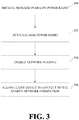
- information identifying the two devices such as MAC addresses for Bluetooth connections, and a shared secret, such as profile information, is shared 400 between the two devices through a shared storage service, such as shown at 130 in Fig. 1 .
- the client device sends 402 the access point device a message indicating that a connection is desired.
- the access point device sends 404 the client device a message indicating that it is ready to connect.
- Both devices start 406 a process through which the devices are configured to recognize each other and automatically connect, such as the Bluetooth pairing process which happens radio-to-radio at the radio/firmware layer in the devices.
- both devices take a link key and a numeric comparison string, which are created by the radios during the connection process, and create 408 a hash with the shared secret using a standard hashing algorithm, such as SHA-256.
- the access point device sends the client device a first part of the resulting hash; the client device sends the access point device the next part of the hash (410). If the response from the client device is correct, then the access point accepts 412 the configuration. Similarly, the client device then sends the access point device the next part of the hash; the access point device sends the client device the next part of the hash (414). If the response from the access point device is correct, then the client device accepts 416 the configuration. After both devices accept, the two devices are configured to recognize each other and securely connect. If at any point an error occurs, then both devices reject the configuration.
- one device generates a random number.
- the random number is sent to the other device. Both devices compute the hash of the shared secret, the random number and the numeric comparison value.
- the other device returns the computed value to the first device, which compares the received value with its own computation.
- This same configuration and process can be performed for multiple client devices connected to the same access point device.
- the access point also can inform the client device of a specific channel to use over the high power radio. This information can be provided in response to the client device requesting access to network sharing, or can be provided as part of the profile information shared through the hosted storage service, or can be provided through any other mechanism.
- the access point device also can include a module that monitors and manages usage of data by the client device(s) connected to it. This module can have a variety of settings for managing such usage.
- the access point device can include a counter for each client device connection that tracks the amount of data, e.g., a number of packets, used by the client device.
- a threshold limit can be established for each connection. This threshold can be a user-defined setting.
- Priority of usage also can be provided as a setting. For example, if the access point device is being used for data transmission, it may take priority over other devices for data transmission.
- the access point device can maintain, for each client device, a quality of service setting to provide more accurate prioritization of communication traffic and aggregate data volume limits.
- Other thresholds associated with a connection such a data rates and cost of data usage can be used to prioritize connections.
- the high power radio can be disabled, meaning it can be turned off completely or made inactive (but in a ready state), so as to conserve battery power.
- a battery power threshold can be set. If the available battery power in the access point device drops under this threshold, then tethering to client devices can be disabled and the high power radio of the access point device can be disabled.
- a time threshold can be set. If a period of inactivity by the client device exceeds the time threshold, then tethering to the client device can be timed out, or disabled. This time out of a connection can improve performance for other connected client devices, and or can improve power utilization of the access point device.
- the high power radio of the access point device can be disabled if no other client device is tethered, so as to conserve battery power.
- the computer can be any of a variety of general purpose or special purpose computing hardware configurations.
- Examples of well-known computers that may be suitable include, but are not limited to, personal computers, server computers, hand-held or laptop devices (for example, media players, notebook, tablet and slate computers, cellular and other mobile phones, personal data assistants, voice recorders), multiprocessor systems, microprocessor-based systems, set top boxes, game consoles, programmable consumer electronics, network PCs, minicomputers, mainframe computers, distributed computing environments that include any of the above systems or devices, and the like.
- FIG. 5 illustrates an example of a suitable computer. This is only one example of a suitable computer and is not intended to suggest any limitation as to the scope of use or functionality of such a computer.
- an example computer 500 in a basic configuration, includes at least one processing unit 502 and memory 504.
- the computer may include multiple processing units and/or additional co-processing units such as graphics processing unit 520.
- memory 504 may be volatile (such as RAM), non-volatile (such as ROM, flash memory, etc.) or some combination of the two. This configuration is illustrated in FIG. 5 by dashed line 506.
- computer 500 may also have additional features/functionality.
- computer 500 may also include additional storage (removable and/or non-removable) including, but not limited to, magnetic or optical disks or tape.
- additional storage is illustrated in FIG. 5 by removable storage 508 and non-removable storage 510.
- Computer storage media includes volatile and nonvolatile, removable and non-removable media implemented in any method or technology for storage of information such as computer program instructions, data structures, program modules or other data.
- Memory 504, removable storage 508 and non-removable storage 510 are all examples of computer storage media.
- Computer storage media includes, but is not limited to, RAM, ROM, EEPROM, flash memory or other memory technology, CD-ROM, digital versatile disks (DVD) or other optical storage, magnetic cassettes, magnetic tape, magnetic disk storage or other magnetic storage devices, or any other medium which can be used to store the desired information and which can accessed by computer 500. Any such computer storage media may be part of computer 500.
- Computer 500 may also contain communications connection(s) 512 that allow the device to communicate with other devices over a communication medium.
- Communication media typically carry computer program instructions, data structures, program modules or other data in a modulated data signal such as a carrier wave or other transport mechanism and include any information delivery media.
- modulated data signal means a signal that has one or more of its characteristics set or changed in such a manner as to encode information in the signal, thereby changing the configuration or state of the receiving device of the signal.
- communication media includes wired media such as a wired network or direct-wired connection, and wireless media such as acoustic, RF, infrared and other wireless media.
- Communications connections 512 are devices that interface with the communication media to transmit data over and receive data from communication media, such as a network interface.
- Computer 500 may have various input device(s) 514 such as a keyboard, mouse, pen, camera, touch input device, and so on.
- Output device(s) 516 such as a display, speakers, a printer, and so on may also be included. All of these devices are well known in the art and need not be discussed at length here.
- Various input and output devices can implement a natural user interface (NUI), which is any interface technology that enables a user to interact with a device in a "natural" manner, free from artificial constraints imposed by input devices such as mice, keyboards, remote controls, and the like.
- NUI natural user interface
- NUI methods include those relying on speech recognition, touch and stylus recognition, gesture recognition both on screen and adjacent to the screen, air gestures, head and eye tracking, voice and speech, vision, touch, gestures, and machine intelligence, and may include the use of touch sensitive displays, voice and speech recognition, intention and goal understanding, motion gesture detection using depth cameras (such as stereoscopic camera systems, infrared camera systems, and other camera systems and combinations of these), motion gesture detection using accelerometers or gyroscopes, facial recognition, three dimensional displays, head, eye, and gaze tracking, immersive augmented reality and virtual reality systems, all of which provide a more natural interface, as well as technologies for sensing brain activity using electric field sensing electrodes (EEG and related methods).
- EEG electric field sensing electrodes
- Each component of this system that operates on a computer generally is implemented by software, such as one or more computer programs, which include computer-executable instructions and/or computer-interpreted instructions, such as program modules, being processed by the computer.
- program modules include routines, programs, objects, components, data structures, and so on, that, when processed by a processing unit, instruct the processing unit to perform particular tasks or implement particular abstract data types.
- This computer system enforces licensing restrictions may be practiced in distributed computing environments where tasks are performed by remote processing devices that are linked through a communications network.
- program modules may be located in both local and remote computer storage media including memory storage devices.
- the functionally described herein can be performed, at least in part, by one or more hardware logic components.
- illustrative types of hardware logic components include Field-programmable Gate Arrays (FPGAs), Program-specific Integrated Circuits (ASICs), Program-specific Standard Products (ASSPs), System-on-a-chip systems (SOCs), Complex Programmable Logic Devices (CPLDs), etc.
Landscapes
- Engineering & Computer Science (AREA)
- Computer Networks & Wireless Communication (AREA)
- Signal Processing (AREA)
- Computer Security & Cryptography (AREA)
- Computer Hardware Design (AREA)
- Computing Systems (AREA)
- General Engineering & Computer Science (AREA)
- Mobile Radio Communication Systems (AREA)
Claims (8)
- Computerimplementierter Prozess, der von einem Prozessor in einem Computer durchgeführt wird, der als eine Zugangspunktvorrichtung (120) betrieben wird, umfassend:Verbinden mit einer Client-Vorrichtung (110) über eine erste Verbindung unter Verwendung einer Kommunikationsvorrichtung mit niedriger Leistung (122), wobei das Verbinden umfasst:Zugreifen auf ein gemeinsames Geheimnis, das auf einem gemeinsamen Speicher (130) gespeichert ist, wobei das gemeinsame Geheimnis und der gemeinsame Speicher über ein Computernetzwerk durch die Zugangspunktvorrichtung und durch die Client-Vorrichtung zugänglich sind,Authentifizieren der Client-Vorrichtung unter Verwendung des gemeinsamen Geheimnisses unter Verwendung einer Kommunikation über die Kommunikationsvorrichtung mit niedriger Leistung und, in Reaktion auf das Authentifizieren der Client-Vorrichtung, automatisches Herstellen der ersten Verbindung über die Kommunikationsvorrichtung mit niedriger Leistung;Empfangen, über die Verbindung unter Verwendung der Kommunikationsvorrichtung mit niedriger Leistung, einer Nachricht von der Client-Vorrichtung, die die Zugangspunktvorrichtung anweist, ein Funkgerät mit hoher Leistung (124) in der Zugangspunktvorrichtung zu aktivieren;Verbinden mit der Client-Vorrichtung über eine zweite Verbindung unter Verwendung des Funkgeräts mit hoher Leistung;Einleiten der gemeinsamen Nutzung einer Netzwerkverbindung der Zugangspunktvorrichtung mit der Client-Vorrichtung unter Verwendung der zweiten Verbindung und des Funkgeräts mit hoher Leistung.
- Computerimplementierter Prozess nach Anspruch 1, ferner umfassend:Erkennen der Nähe der Client-Vorrichtung zu der Zugangspunktvorrichtung; undwobei das Verbinden mit der Client-Vorrichtung über die Verbindung unter Verwendung der Kommunikationsvorrichtung mit niedriger Leistung in Reaktion auf eine Erkennung der Zugangspunktvorrichtung als sich in der Nähe der Client-Vorrichtung befindlich eingeleitet wird.
- Computerimplementierter Prozess nach Anspruch 2, ferner umfassend:Zugreifen auf Profilinformationen der Client-Vorrichtung von einem Hostingdienst durch die Zugangspunktvorrichtung.
- Computerimplementierter Prozess nach Anspruch 1, ferner umfassend:Festlegen eines Schwellenwerts für Datennutzung durch die Client-Vorrichtung;Drosseln des Zugangs zu der gemeinsamen Netzwerkverbindung durch die Client-Vorrichtung, wenn die Datennutzung durch die Client-Vorrichtung den Schwellenwert überschreitet.
- Computerimplementierter Prozess nach Anspruch 1, wobei die Zugangspunktvorrichtung die gemeinsame Nutzung der Netzwerkverbindung beendet, wenn die verfügbare Batterieleistung für die Zugangspunktvorrichtung unter einen Schwellenwert fällt.
- Computerimplementierter Prozess nach Anspruch 1, umfassend:gemeinsames Nutzen des Netzwerkzugangs mit der Client-Vorrichtung über ein Funkgerät mit hoher Leistung; Überwachen der Betriebsbedingungen der Zugangspunktvorrichtung;in Reaktion auf die Betriebsbedingungen Beenden der Verbindung mit der Client-Vorrichtung auf dem Funkgerät mit hoher Leistung.
- Computerimplementierter Prozess nach Anspruch 6, wobei die Betriebsbedingungen einschließen, dass die verfügbare Batterieleistung der Zugangspunktvorrichtung unter einen Schwellenwert fällt.
- Computerimplementierter Prozess nach Anspruch 6, wobei die Betriebsbedingungen eine Zeitüberschreitungsbedingung aufgrund von Inaktivität auf der Verbindung über das Funkgerät mit hoher Leistung einschließen.
Applications Claiming Priority (2)
| Application Number | Priority Date | Filing Date | Title |
|---|---|---|---|
| US13/889,341 US9392067B2 (en) | 2013-05-07 | 2013-05-07 | Efficient automatic sharing of network access among devices |
| PCT/US2013/059326 WO2014182324A1 (en) | 2013-05-07 | 2013-09-12 | Efficient automatic sharing of network access among devices |
Publications (2)
| Publication Number | Publication Date |
|---|---|
| EP2995135A1 EP2995135A1 (de) | 2016-03-16 |
| EP2995135B1 true EP2995135B1 (de) | 2018-01-03 |
Family
ID=49253409
Family Applications (1)
| Application Number | Title | Priority Date | Filing Date |
|---|---|---|---|
| EP13767183.0A Active EP2995135B1 (de) | 2013-05-07 | 2013-09-12 | Effiziente automatische teilung von netzwerken zwischen vorrichtungen |
Country Status (5)
| Country | Link |
|---|---|
| US (1) | US9392067B2 (de) |
| EP (1) | EP2995135B1 (de) |
| KR (1) | KR102094574B1 (de) |
| CN (1) | CN105557036B (de) |
| WO (1) | WO2014182324A1 (de) |
Families Citing this family (22)
| Publication number | Priority date | Publication date | Assignee | Title |
|---|---|---|---|---|
| EP2709006A1 (de) * | 2012-09-14 | 2014-03-19 | Alcatel Lucent | Periphere Schnittstelle für verborgenes IaaS |
| KR20150044330A (ko) | 2013-10-16 | 2015-04-24 | 삼성전자주식회사 | 디바이스가 AP(Access Point)로 동작하는 방법, 디바이스의 데이터 전송 방법 및 디바이스 |
| KR20150060275A (ko) * | 2013-11-26 | 2015-06-03 | 삼성전자주식회사 | 전자장치 및 전자장치의 데이터서비스 제공방법 |
| FR3019437A1 (fr) * | 2014-03-28 | 2015-10-02 | Orange | Technique de gestion d'un etat d'activation d'un reseau d'acces radio dans un reseau local |
| WO2016003943A1 (en) * | 2014-06-29 | 2016-01-07 | Tetherball Technology, LLC | Automatic wireless grid access sharing and monetization from a mobile device app |
| EP3226623B1 (de) * | 2014-12-16 | 2020-07-15 | Huawei Technologies Co., Ltd. | Verfahren zum aufwecken eines wifi-netzwerks und endgerät |
| KR102354011B1 (ko) * | 2015-01-06 | 2022-01-21 | 삼성전자주식회사 | 테더링 제어 방법 및 그 전자 장치 |
| KR102461009B1 (ko) | 2016-01-29 | 2022-11-01 | 삼성전자 주식회사 | 테더링 서비스를 제공하는 방법 및 이를 사용하는 전자 장치 |
| US10235516B2 (en) * | 2016-05-10 | 2019-03-19 | Cisco Technology, Inc. | Method for authenticating a networked endpoint using a physical (power) challenge |
| WO2017223227A1 (en) * | 2016-06-21 | 2017-12-28 | Tetherball Technology, LLC | Automatic wireless grid access sharing and monetization from a mobile device application that receives credentials over a wireless channel |
| KR102642689B1 (ko) * | 2016-11-16 | 2024-03-05 | 삼성전자주식회사 | 전자 장치 및 그 트래픽 제어 방법 |
| WO2018194574A1 (en) | 2017-04-19 | 2018-10-25 | Hewlett-Packard Development Company, L.P. | Network connection selections based on quality scores |
| KR102648507B1 (ko) | 2018-06-12 | 2024-03-18 | 삼성전자 주식회사 | 전자 장치 및 전자 장치의 무선랜 중계기능 제어 방법 |
| US10966282B2 (en) | 2018-12-31 | 2021-03-30 | T-Mobile Usa, Inc. | Providing network access via mobile device peer to peer sharing |
| US11212739B2 (en) | 2019-07-26 | 2021-12-28 | Nokia Technologies Oy | Establishing tethering cells remotely |
| CN113316089B (zh) * | 2020-02-27 | 2025-05-06 | 开利公司 | 用于降低功率消耗的动态无线连接配置 |
| KR20220104994A (ko) * | 2021-01-19 | 2022-07-26 | 삼성전자주식회사 | 무선통신 시스템에서 액세스 포인트의 정보를 제공하는 전자 장치 및 그 방법 |
| EP4290928A4 (de) | 2021-03-08 | 2024-07-31 | Samsung Electronics Co., Ltd. | Elektronische vorrichtung zur bereitstellung eines tethering-dienstes und verfahren dafür |
| US12495339B2 (en) | 2021-06-29 | 2025-12-09 | Arlo Technologies, Inc. | Detection and mitigation of a network outage for smart devices in a networked system |
| US12298019B2 (en) | 2021-07-13 | 2025-05-13 | Arlo Technologies, Inc. | Battery-powered wireless electronic device switchable between high and low power operating modes |
| US12614388B2 (en) | 2021-09-20 | 2026-04-28 | Arlo Technologies, Inc. | Image convergence in a smart security camera system with a secondary processor |
| US11942609B2 (en) | 2021-10-29 | 2024-03-26 | Texas Instruments Incorporated | Reduced power wireless battery management system |
Family Cites Families (9)
| Publication number | Priority date | Publication date | Assignee | Title |
|---|---|---|---|---|
| US20070217335A1 (en) * | 2006-03-16 | 2007-09-20 | Utstarcom, Inc. | Method and apparatus to facilitate communication resource usage control |
| US7978652B2 (en) * | 2008-01-23 | 2011-07-12 | Microsoft Corporation | Wireless communications environment overlay |
| US8935436B2 (en) * | 2009-02-18 | 2015-01-13 | Qualcomm Incorporated | Wakeup trigger to support multiple user interfaces, environments, and/or virtual machines |
| US8335854B2 (en) | 2009-07-21 | 2012-12-18 | Empire Technology Development Llc | Performing services on behalf of low-power devices |
| US8249499B2 (en) | 2009-07-31 | 2012-08-21 | Sierra Wireless, Inc. | Method, system and device for initiating wireless communication |
| KR101094994B1 (ko) * | 2009-09-28 | 2011-12-19 | 금오공과대학교 산학협력단 | 무선 랜용 우선 순위 접근에 기반한 수락 제어 방법 |
| KR101682385B1 (ko) * | 2010-05-14 | 2016-12-05 | 삼성전자 주식회사 | 와이파이 디바이스의 와이파이 서비스 제공 방법 및 시스템 |
| US8966292B2 (en) | 2011-01-03 | 2015-02-24 | Qualcomm Incorporated | Performance improvements in a wireless client terminal using assistance from a proxy device |
| US9059862B2 (en) * | 2012-03-13 | 2015-06-16 | Verizon Patent And Licensing Inc. | Evolved packet core (EPC) network failure prevention |
-
2013
- 2013-05-07 US US13/889,341 patent/US9392067B2/en active Active
- 2013-09-12 KR KR1020157034641A patent/KR102094574B1/ko not_active Expired - Fee Related
- 2013-09-12 EP EP13767183.0A patent/EP2995135B1/de active Active
- 2013-09-12 CN CN201380076389.1A patent/CN105557036B/zh active Active
- 2013-09-12 WO PCT/US2013/059326 patent/WO2014182324A1/en not_active Ceased
Also Published As
| Publication number | Publication date |
|---|---|
| US9392067B2 (en) | 2016-07-12 |
| CN105557036A (zh) | 2016-05-04 |
| US20140337923A1 (en) | 2014-11-13 |
| CN105557036B (zh) | 2019-06-25 |
| WO2014182324A1 (en) | 2014-11-13 |
| KR102094574B1 (ko) | 2020-03-27 |
| KR20160009599A (ko) | 2016-01-26 |
| EP2995135A1 (de) | 2016-03-16 |
Similar Documents
| Publication | Publication Date | Title |
|---|---|---|
| US9392067B2 (en) | Efficient automatic sharing of network access among devices | |
| JP6754016B1 (ja) | 解除および再中断時における非アクティブパラメータの処理 | |
| US10341860B2 (en) | Learned dual band WIFI network association | |
| EP2941855B1 (de) | Authentifizierung eines drahtlosandockers für einen drahtlosen andockdienst | |
| US9078087B2 (en) | Method and apparatus for forming Wi-Fi P2P group using Wi-Fi direct | |
| US10085211B2 (en) | Communication of processor state information | |
| CN103444232B (zh) | 智能连接管理器 | |
| US20150351004A1 (en) | Client-initiated tethering for electronic devices | |
| EP3031223B1 (de) | Verfahren und vorrichtung für wifi-direktverbindung | |
| US20140214261A1 (en) | Remotely monitoring vehicle information using Wi-Fi Direct | |
| JP2015508273A (ja) | ピアツーピアリンクを介した共有ネットワークアクセス | |
| CN114731515A (zh) | 无线电资源控制消息的完整性保护 | |
| CN108496403B (zh) | 一种工作模式的切换方法及用户设备 | |
| US9654552B2 (en) | Methods and systems for delegating group ownership for the formation of a new group | |
| US10993090B2 (en) | Network access method, apparatus, and system | |
| JP2020505676A (ja) | アプリケーション表示方法及び関連製品 | |
| WO2019218951A1 (zh) | 一种传输文件的方法及终端 | |
| US20190268951A1 (en) | Communication Method and Device | |
| CN104159259A (zh) | 无线通信方法及无线通信装置 | |
| WO2022218131A1 (zh) | 数据传输方法、系统、电子设备及存储介质 | |
| KR20160079835A (ko) | 발견 프로브를 통한 wi―fi direct 서비스들의 발견 | |
| CN112702739B (zh) | 无线网络共享方法、装置、可读存储介质及移动端 | |
| CN105721436A (zh) | Wi-Fi热点共享方法及移动终端 |
Legal Events
| Date | Code | Title | Description |
|---|---|---|---|
| PUAI | Public reference made under article 153(3) epc to a published international application that has entered the european phase |
Free format text: ORIGINAL CODE: 0009012 |
|
| 17P | Request for examination filed |
Effective date: 20151020 |
|
| AK | Designated contracting states |
Kind code of ref document: A1 Designated state(s): AL AT BE BG CH CY CZ DE DK EE ES FI FR GB GR HR HU IE IS IT LI LT LU LV MC MK MT NL NO PL PT RO RS SE SI SK SM TR |
|
| AX | Request for extension of the european patent |
Extension state: BA ME |
|
| DAX | Request for extension of the european patent (deleted) | ||
| GRAP | Despatch of communication of intention to grant a patent |
Free format text: ORIGINAL CODE: EPIDOSNIGR1 |
|
| INTG | Intention to grant announced |
Effective date: 20170720 |
|
| GRAS | Grant fee paid |
Free format text: ORIGINAL CODE: EPIDOSNIGR3 |
|
| GRAA | (expected) grant |
Free format text: ORIGINAL CODE: 0009210 |
|
| AK | Designated contracting states |
Kind code of ref document: B1 Designated state(s): AL AT BE BG CH CY CZ DE DK EE ES FI FR GB GR HR HU IE IS IT LI LT LU LV MC MK MT NL NO PL PT RO RS SE SI SK SM TR |
|
| REG | Reference to a national code |
Ref country code: GB Ref legal event code: FG4D |
|
| REG | Reference to a national code |
Ref country code: CH Ref legal event code: EP Ref country code: AT Ref legal event code: REF Ref document number: 961329 Country of ref document: AT Kind code of ref document: T Effective date: 20180115 |
|
| REG | Reference to a national code |
Ref country code: IE Ref legal event code: FG4D |
|
| REG | Reference to a national code |
Ref country code: DE Ref legal event code: R096 Ref document number: 602013031660 Country of ref document: DE |
|
| REG | Reference to a national code |
Ref country code: NL Ref legal event code: FP |
|
| REG | Reference to a national code |
Ref country code: LT Ref legal event code: MG4D |
|
| REG | Reference to a national code |
Ref country code: AT Ref legal event code: MK05 Ref document number: 961329 Country of ref document: AT Kind code of ref document: T Effective date: 20180103 |
|
| PG25 | Lapsed in a contracting state [announced via postgrant information from national office to epo] |
Ref country code: ES Free format text: LAPSE BECAUSE OF FAILURE TO SUBMIT A TRANSLATION OF THE DESCRIPTION OR TO PAY THE FEE WITHIN THE PRESCRIBED TIME-LIMIT Effective date: 20180103 Ref country code: HR Free format text: LAPSE BECAUSE OF FAILURE TO SUBMIT A TRANSLATION OF THE DESCRIPTION OR TO PAY THE FEE WITHIN THE PRESCRIBED TIME-LIMIT Effective date: 20180103 Ref country code: NO Free format text: LAPSE BECAUSE OF FAILURE TO SUBMIT A TRANSLATION OF THE DESCRIPTION OR TO PAY THE FEE WITHIN THE PRESCRIBED TIME-LIMIT Effective date: 20180403 Ref country code: LT Free format text: LAPSE BECAUSE OF FAILURE TO SUBMIT A TRANSLATION OF THE DESCRIPTION OR TO PAY THE FEE WITHIN THE PRESCRIBED TIME-LIMIT Effective date: 20180103 Ref country code: FI Free format text: LAPSE BECAUSE OF FAILURE TO SUBMIT A TRANSLATION OF THE DESCRIPTION OR TO PAY THE FEE WITHIN THE PRESCRIBED TIME-LIMIT Effective date: 20180103 Ref country code: CY Free format text: LAPSE BECAUSE OF FAILURE TO SUBMIT A TRANSLATION OF THE DESCRIPTION OR TO PAY THE FEE WITHIN THE PRESCRIBED TIME-LIMIT Effective date: 20180103 |
|
| PG25 | Lapsed in a contracting state [announced via postgrant information from national office to epo] |
Ref country code: IS Free format text: LAPSE BECAUSE OF FAILURE TO SUBMIT A TRANSLATION OF THE DESCRIPTION OR TO PAY THE FEE WITHIN THE PRESCRIBED TIME-LIMIT Effective date: 20180503 Ref country code: GR Free format text: LAPSE BECAUSE OF FAILURE TO SUBMIT A TRANSLATION OF THE DESCRIPTION OR TO PAY THE FEE WITHIN THE PRESCRIBED TIME-LIMIT Effective date: 20180404 Ref country code: SE Free format text: LAPSE BECAUSE OF FAILURE TO SUBMIT A TRANSLATION OF THE DESCRIPTION OR TO PAY THE FEE WITHIN THE PRESCRIBED TIME-LIMIT Effective date: 20180103 Ref country code: LV Free format text: LAPSE BECAUSE OF FAILURE TO SUBMIT A TRANSLATION OF THE DESCRIPTION OR TO PAY THE FEE WITHIN THE PRESCRIBED TIME-LIMIT Effective date: 20180103 Ref country code: PL Free format text: LAPSE BECAUSE OF FAILURE TO SUBMIT A TRANSLATION OF THE DESCRIPTION OR TO PAY THE FEE WITHIN THE PRESCRIBED TIME-LIMIT Effective date: 20180103 Ref country code: RS Free format text: LAPSE BECAUSE OF FAILURE TO SUBMIT A TRANSLATION OF THE DESCRIPTION OR TO PAY THE FEE WITHIN THE PRESCRIBED TIME-LIMIT Effective date: 20180103 Ref country code: BG Free format text: LAPSE BECAUSE OF FAILURE TO SUBMIT A TRANSLATION OF THE DESCRIPTION OR TO PAY THE FEE WITHIN THE PRESCRIBED TIME-LIMIT Effective date: 20180403 Ref country code: AT Free format text: LAPSE BECAUSE OF FAILURE TO SUBMIT A TRANSLATION OF THE DESCRIPTION OR TO PAY THE FEE WITHIN THE PRESCRIBED TIME-LIMIT Effective date: 20180103 |
|
| REG | Reference to a national code |
Ref country code: DE Ref legal event code: R097 Ref document number: 602013031660 Country of ref document: DE |
|
| PG25 | Lapsed in a contracting state [announced via postgrant information from national office to epo] |
Ref country code: IT Free format text: LAPSE BECAUSE OF FAILURE TO SUBMIT A TRANSLATION OF THE DESCRIPTION OR TO PAY THE FEE WITHIN THE PRESCRIBED TIME-LIMIT Effective date: 20180103 Ref country code: RO Free format text: LAPSE BECAUSE OF FAILURE TO SUBMIT A TRANSLATION OF THE DESCRIPTION OR TO PAY THE FEE WITHIN THE PRESCRIBED TIME-LIMIT Effective date: 20180103 Ref country code: EE Free format text: LAPSE BECAUSE OF FAILURE TO SUBMIT A TRANSLATION OF THE DESCRIPTION OR TO PAY THE FEE WITHIN THE PRESCRIBED TIME-LIMIT Effective date: 20180103 Ref country code: AL Free format text: LAPSE BECAUSE OF FAILURE TO SUBMIT A TRANSLATION OF THE DESCRIPTION OR TO PAY THE FEE WITHIN THE PRESCRIBED TIME-LIMIT Effective date: 20180103 |
|
| PLBE | No opposition filed within time limit |
Free format text: ORIGINAL CODE: 0009261 |
|
| STAA | Information on the status of an ep patent application or granted ep patent |
Free format text: STATUS: NO OPPOSITION FILED WITHIN TIME LIMIT |
|
| PG25 | Lapsed in a contracting state [announced via postgrant information from national office to epo] |
Ref country code: DK Free format text: LAPSE BECAUSE OF FAILURE TO SUBMIT A TRANSLATION OF THE DESCRIPTION OR TO PAY THE FEE WITHIN THE PRESCRIBED TIME-LIMIT Effective date: 20180103 Ref country code: CZ Free format text: LAPSE BECAUSE OF FAILURE TO SUBMIT A TRANSLATION OF THE DESCRIPTION OR TO PAY THE FEE WITHIN THE PRESCRIBED TIME-LIMIT Effective date: 20180103 Ref country code: SK Free format text: LAPSE BECAUSE OF FAILURE TO SUBMIT A TRANSLATION OF THE DESCRIPTION OR TO PAY THE FEE WITHIN THE PRESCRIBED TIME-LIMIT Effective date: 20180103 Ref country code: SM Free format text: LAPSE BECAUSE OF FAILURE TO SUBMIT A TRANSLATION OF THE DESCRIPTION OR TO PAY THE FEE WITHIN THE PRESCRIBED TIME-LIMIT Effective date: 20180103 |
|
| 26N | No opposition filed |
Effective date: 20181005 |
|
| PG25 | Lapsed in a contracting state [announced via postgrant information from national office to epo] |
Ref country code: SI Free format text: LAPSE BECAUSE OF FAILURE TO SUBMIT A TRANSLATION OF THE DESCRIPTION OR TO PAY THE FEE WITHIN THE PRESCRIBED TIME-LIMIT Effective date: 20180103 |
|
| PG25 | Lapsed in a contracting state [announced via postgrant information from national office to epo] |
Ref country code: MC Free format text: LAPSE BECAUSE OF FAILURE TO SUBMIT A TRANSLATION OF THE DESCRIPTION OR TO PAY THE FEE WITHIN THE PRESCRIBED TIME-LIMIT Effective date: 20180103 |
|
| REG | Reference to a national code |
Ref country code: CH Ref legal event code: PL |
|
| GBPC | Gb: european patent ceased through non-payment of renewal fee |
Effective date: 20180912 |
|
| REG | Reference to a national code |
Ref country code: BE Ref legal event code: MM Effective date: 20180930 |
|
| REG | Reference to a national code |
Ref country code: IE Ref legal event code: MM4A |
|
| PG25 | Lapsed in a contracting state [announced via postgrant information from national office to epo] |
Ref country code: LU Free format text: LAPSE BECAUSE OF NON-PAYMENT OF DUE FEES Effective date: 20180912 |
|
| PG25 | Lapsed in a contracting state [announced via postgrant information from national office to epo] |
Ref country code: IE Free format text: LAPSE BECAUSE OF NON-PAYMENT OF DUE FEES Effective date: 20180912 |
|
| PG25 | Lapsed in a contracting state [announced via postgrant information from national office to epo] |
Ref country code: BE Free format text: LAPSE BECAUSE OF NON-PAYMENT OF DUE FEES Effective date: 20180930 Ref country code: FR Free format text: LAPSE BECAUSE OF NON-PAYMENT OF DUE FEES Effective date: 20180930 Ref country code: CH Free format text: LAPSE BECAUSE OF NON-PAYMENT OF DUE FEES Effective date: 20180930 Ref country code: LI Free format text: LAPSE BECAUSE OF NON-PAYMENT OF DUE FEES Effective date: 20180930 |
|
| PG25 | Lapsed in a contracting state [announced via postgrant information from national office to epo] |
Ref country code: GB Free format text: LAPSE BECAUSE OF NON-PAYMENT OF DUE FEES Effective date: 20180912 |
|
| PG25 | Lapsed in a contracting state [announced via postgrant information from national office to epo] |
Ref country code: MT Free format text: LAPSE BECAUSE OF NON-PAYMENT OF DUE FEES Effective date: 20180912 |
|
| PG25 | Lapsed in a contracting state [announced via postgrant information from national office to epo] |
Ref country code: TR Free format text: LAPSE BECAUSE OF FAILURE TO SUBMIT A TRANSLATION OF THE DESCRIPTION OR TO PAY THE FEE WITHIN THE PRESCRIBED TIME-LIMIT Effective date: 20180103 |
|
| PG25 | Lapsed in a contracting state [announced via postgrant information from national office to epo] |
Ref country code: PT Free format text: LAPSE BECAUSE OF FAILURE TO SUBMIT A TRANSLATION OF THE DESCRIPTION OR TO PAY THE FEE WITHIN THE PRESCRIBED TIME-LIMIT Effective date: 20180103 |
|
| PG25 | Lapsed in a contracting state [announced via postgrant information from national office to epo] |
Ref country code: HU Free format text: LAPSE BECAUSE OF FAILURE TO SUBMIT A TRANSLATION OF THE DESCRIPTION OR TO PAY THE FEE WITHIN THE PRESCRIBED TIME-LIMIT; INVALID AB INITIO Effective date: 20130912 Ref country code: MK Free format text: LAPSE BECAUSE OF NON-PAYMENT OF DUE FEES Effective date: 20180103 |
|
| P01 | Opt-out of the competence of the unified patent court (upc) registered |
Effective date: 20230512 |
|
| PGFP | Annual fee paid to national office [announced via postgrant information from national office to epo] |
Ref country code: NL Payment date: 20230822 Year of fee payment: 11 |
|
| REG | Reference to a national code |
Ref country code: NL Ref legal event code: MM Effective date: 20241001 |
|
| PG25 | Lapsed in a contracting state [announced via postgrant information from national office to epo] |
Ref country code: NL Free format text: LAPSE BECAUSE OF NON-PAYMENT OF DUE FEES Effective date: 20241001 |
|
| PGFP | Annual fee paid to national office [announced via postgrant information from national office to epo] |
Ref country code: DE Payment date: 20250820 Year of fee payment: 13 |