EP2994789B1 - Stereokomparator zum zusammenbau und zur prüfung von stereo-endoskopen - Google Patents
Stereokomparator zum zusammenbau und zur prüfung von stereo-endoskopen Download PDFInfo
- Publication number
- EP2994789B1 EP2994789B1 EP14794632.1A EP14794632A EP2994789B1 EP 2994789 B1 EP2994789 B1 EP 2994789B1 EP 14794632 A EP14794632 A EP 14794632A EP 2994789 B1 EP2994789 B1 EP 2994789B1
- Authority
- EP
- European Patent Office
- Prior art keywords
- optical
- deflecting component
- stereo
- beam splitter
- optical axis
- Prior art date
- Legal status (The legal status is an assumption and is not a legal conclusion. Google has not performed a legal analysis and makes no representation as to the accuracy of the status listed.)
- Active
Links
Images




Classifications
-
- G—PHYSICS
- G02—OPTICS
- G02B—OPTICAL ELEMENTS, SYSTEMS OR APPARATUS
- G02B23/00—Telescopes, e.g. binoculars; Periscopes; Instruments for viewing the inside of hollow bodies; Viewfinders; Optical aiming or sighting devices
- G02B23/24—Instruments or systems for viewing the inside of hollow bodies, e.g. fibrescopes
- G02B23/2407—Optical details
- G02B23/2415—Stereoscopic endoscopes
-
- A—HUMAN NECESSITIES
- A61—MEDICAL OR VETERINARY SCIENCE; HYGIENE
- A61B—DIAGNOSIS; SURGERY; IDENTIFICATION
- A61B1/00—Instruments for performing medical examinations of the interior of cavities or tubes of the body by visual or photographical inspection, e.g. endoscopes; Illuminating arrangements therefor
- A61B1/00002—Operational features of endoscopes
- A61B1/00057—Operational features of endoscopes provided with means for testing or calibration
-
- A—HUMAN NECESSITIES
- A61—MEDICAL OR VETERINARY SCIENCE; HYGIENE
- A61B—DIAGNOSIS; SURGERY; IDENTIFICATION
- A61B1/00—Instruments for performing medical examinations of the interior of cavities or tubes of the body by visual or photographical inspection, e.g. endoscopes; Illuminating arrangements therefor
- A61B1/00163—Optical arrangements
- A61B1/00193—Optical arrangements adapted for stereoscopic vision
-
- G—PHYSICS
- G02—OPTICS
- G02B—OPTICAL ELEMENTS, SYSTEMS OR APPARATUS
- G02B27/00—Optical systems or apparatus not provided for by any of the groups G02B1/00 - G02B26/00, G02B30/00
- G02B27/10—Beam splitting or combining systems
- G02B27/1073—Beam splitting or combining systems characterized by manufacturing or alignment methods
-
- G—PHYSICS
- G02—OPTICS
- G02B—OPTICAL ELEMENTS, SYSTEMS OR APPARATUS
- G02B27/00—Optical systems or apparatus not provided for by any of the groups G02B1/00 - G02B26/00, G02B30/00
- G02B27/10—Beam splitting or combining systems
- G02B27/14—Beam splitting or combining systems operating by reflection only
- G02B27/144—Beam splitting or combining systems operating by reflection only using partially transparent surfaces without spectral selectivity
Definitions
- the present invention is directed to an apparatus for inspecting the performance of an optical assembly. More particularly, the present invention is directed to stereo comparator configured for use with a stereo endoscope for adjusting and aligning an optical assembly of the stereo endoscope, for example, in connection with the repair of the endoscope.
- endoscopes are delicate optical instruments that are introduced into technical and human cavities for inspecting the interior of the cavities.
- Such endoscopes can be rigid endoscopes containing a lens system, flexible endoscopes containing a flexible image guiding bundle or video endoscopes.
- stereo endoscopes are mono endoscopes, though stereo endoscopes have been known in the art since 1904, when Louis & H. Loewenstein received a German patent for a stereo endoscope.
- Stereo endoscopes are more complex and have a lower brightness than mono endoscope because the cross section available for the optical system of a stereo endoscope is divided between a left image channel and a right image channel. Further, because stereo endoscopes include left optical and right optical channels, those channels must be properly aligned so that the images of the two optical channels overlap within very tight tolerances.
- stereo endoscopes In spite of the complexity and shortcomings of stereo endoscopes, their use has proliferated with the increased demand and execution of minimally invasive surgical procedures, which require handling of surgical instruments under visual control. Mono endoscopes have shown to be poorly configured for such procedures. As a consequence, special endoscopic procedure stereo endoscopes have been developed and in some cases successfully used. The demand for stereo endoscopes has also increased with the advent of robotic surgical procedures and the availability of stereo displays. Because of the rise in use of stereo endoscopes, challenges have arisen in connection with the repair of damaged stereo endoscopes, and particularly, with the inspection, testing and aligning of stereo endoscope optical channels.
- the left optical channel and the right optical channel are evaluated independently to ensure that each optical channel meets certain specified optical parameters and that the quality of the transmitted image for the channel is clear and crisp.
- the two optical channels are aligned relative to one another.
- the two optical channels are observed relative to an optimal position.
- the optical elements that compose the optical trains of the left optical channel and the right optical channel are moved.
- the optical parameters and the optical qualities of the two optical channels can change to such a degree that they no longer meet the desired optical parameters. Therefore, it is imperative to control the optical parameters and the optical qualities of the two optical channels, as well as the stereoscopic alignment, of the two channels relative to one another during the alignment process.
- Stereo endoscope manufacturers utilize stereo cameras and monitor systems, as part of the stereo endoscopic equipment, to control the optical parameters and the optical qualities of the two optical channels during the alignment and assembly process. Independent service providers who repair stereo endoscopes often do not have access to such stereo cameras and monitor systems. Additionally, hospitals and physicians often do not have access to such equipment when it is desired to inspect and test a stereo endoscope to ensure that the endoscope is proper working condition. This can occur when stereo documentation system of the endoscope manufacturer is not available or the equipment is in use or already sterilized.
- an optical tool that can be used in conjunction with monoscopic equipment to test and compare the quality of the right and left optical trains that compose a stereo endoscope optical system, as well as the stereoscopic alignment of the two optical systems relative to one another.
- Such a tool should be simple to use, stably constructed and manufactured at a reasonable cost.
- Such a tool could be used at several alignment stations in a repair facility, as well as be integrated in a field test kit.
- US-A-2011/0043612 relates to a dual tube stereoscope, the field stop capable of limiting light passing through one of two optical parts.
- US 2011/0295071 is a stereoscopic coupler for mechanically and optically coupling a stereo endoscope to a stereo endoscope camera.
- the present invention is directed to a stereo comparator adapter for stereo endoscopes as described in claim 1 that can be used as an assembly tool in a repair facility, hospital or surgical clinic.
- the adapter can be added to existing stationary or portable test equipment for endoscopes.
- the stereo comparator adapter can be used to control the effects of adjustment and alignment steps of the right and left optical channels of a stereo endoscope.
- the stereo comparator adapter can also be used during assembly of a repaired stereo endoscope to check if both optical channels are clear and transmit equally crisp images.
- the test equipment can be used to test each of the two optical channels independently, as well as to test the stereoscopic alignment of the left and right channels relative to one another.
- Mono endoscopes can be tested using the adapter using the same equipment and in the same manner described in prior disclosures.
- Stereo endoscopes are inspected for damage of the shaft and the illumination system in the same manner as mono endoscopes.
- the stereo comparator of the present invention can be used to inspect the optical train of the two optical systems composing the left and right optical channels of a stereo endoscope and the stereoscopic alignment of the two channels relative to one another.
- a method of inspecting an endoscope is disclosed in claim 14.
- the stereo comparator adapter is configured to connect to a proximal side of a stereo endoscope.
- the adapter includes a conventional monoscopic eyepiece through which a stereo endoscopic image transmitted by the stereo endoscope can be observed.
- the image can be observed in a manner where both optical channels of the stereo endoscope appear overlapped. Additionally, by blocking one of the two optical channels of the stereo endoscope, the image can be observed in a manner where the unblocked channel can be observed and individually inspected.
- the adapter utilizes a cubic beam splitter to combine the right and left optical channels.
- a cube is made from two triangular glass prisms which are glued together at their base using polyester, epoxy, or urethane-based adhesives.
- a special optical coating on one of the hypotenuse of the glass prism is used, such that half of the light incident through one port, i.e., face of the cube, is reflected and the other half is transmitted.
- a beam splitter is typically used to separate an optical beam into two optical beams, each of the two optical beams including 50% of the beam intensity and exiting the beam splitter at a right angle relative to one another.
- a beam splitter When a beam splitter is used in a reversed mode, two optical beams entering the beam splitter at a right angle relative to one another are combined or overlaid so that two beams exit the beam splitter at a right angle to one another, each of the two beams including 50% of the intensity of the first beam and the second beam.
- This effect is used in the stereo comparator adapter of the present invention to combine left and right optical channels of a stereo endoscope.
- the optical axes of the left and right optical channels are deflected towards a common center axis of the stereo endoscope by deflecting the optical axis of one of the optical channels 90° towards the common center axis of the stereo endoscope with a 45° mirror or a 45° prism and deflecting this optical axis with another 45° prism in the direction of the common center axis of the stereo endoscope.
- the optical axis of the second optical channel is deflected by a 45° prism towards the common center axes of the stereo endoscope.
- the optical axes of the two optical channels enter the beam splitter at a right angle relative to one another and exit the beam splitter overlaid.
- the two overlapped beams exit the beam splitter at a right angle, each containing 50% of the intensity of the overlaid beams.
- the overlaid beam exiting the beam splitter in the direction of the common center axis of the stereo endoscope can be observed through an eyepiece, or if a mechanical adapter is integrated an endoscopic mono camera can be used to observe the overlaid beam.
- a mechanical switch can be used to let both optical channels enter the beam splitter. This mechanical switch can be used also in a left or right position to block out one of the channels to enable the inspection of the optical parameters and the clarity and sharpness of the image of the unblocked optical channel.
- adapter 10 for a stereo endoscope.
- adapter 10 includes a distal end including an endoscope coupler portion 12, a proximal end including an eye piece portion 14 and a fixture portion 16 coupled to and between coupler portion 12 and eyepiece portion 14 for supporting an optical assembly 18.
- optical assembly 18 is arranged to receive right and left channel images from the stereo endoscope, overlay the right and left channel images and transmit the overlaid right and left images through eyepiece portion 14 to a user's eye, a camera or other device capable of displaying the overlaid images for inspection by the user. Further, by selectively blocking transmission of the right channel image and the left channel image, a user can inspect the right and left channel images independently.
- coupler portion 12 includes a cylindrical body 20 configured for coupling to a proximal end of a stereo endoscope.
- Cylindrical body 20 includes a central opening 22 into which the proximal end of the stereo endoscope is inserted during use of adapter 10.
- the design of cylindrical body 20 depends on the design of the proximal end of the stereo endoscope and therefore may vary.
- the proximal end of the stereo endoscope may include an eyepiece so that central opening 22 and cylindrical body 20 are configured for receiving the stereo endoscope eyepiece.
- cylindrical body 20 includes means for allowing proper optical alignment there between, the design of such means depending upon the configuration of the proximal end of the stereo endoscope.
- optical assembly 18 is configured for overlaying a right channel image of the stereo endoscope, the right channel image having a right optical axis 24, and a left channel image of the stereo endoscope, the left channel image having a left optical axis 26.
- Optical assembly utilizes a cubic beam splitter 28 to combine or overlay the right and left channel images.
- Cubic beam splitter 28 is constructed from two triangular glass prisms 30, 32 which are glued together at their respective bases. A special optical coating on one of the hypotenuse of prisms 30 or 32 is used, such that half of the light incident through one face of beam splitter 28 is reflected and the other half is transmitted.
- Cubic beam splitter 28 operates by receiving the right and left channel images at a right angle relative to one another and combining the two channel images so that each channel image splits at a right angle, with each split or divided channel image including 50% of the intensity of the right channel image and the left channel image.
- right optical axis 24 and left optical axis 26 of the left and right optical channels are deflected towards a common center axis of the stereo endoscope. This is accomplished by deflecting right optical axis 24 at a right angle towards beam splitter 28 and the common center axis of the stereo endoscope with a 45° prism 34 having a mirrored back 36.
- left optical axis 26 is deflected at a right angle towards the common center axis of the stereo endoscope with a 45° prism 38 and then deflected again with another 45° prism 40 in the direction of the common center axis of the stereo endoscope.
- the channel images associated with right optical axis 24 and left optical axis 26 enter cubic beam splitter 28 at a right angle relative to one another and exit cubic beam splitter 28 overlaid as a pair of combined channel images extending along respective optical axes 42, 44.
- each resulting overlaid optical axis 42, 44 contains 50% of the intensity of each of the right and the left channel images.
- Each optical axis 42, 44 can be observed by a user as further described below.
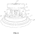
- fixture portion 16 is constructed from a semi-cylindrical body 46 having along the diameter thereof a support surface 48 including three groves including a center groove 50, a right groove 52 and a left groove 54, each being configured for receiving respective optical components 28, 34, 38 and 40 of optical assembly 18.
- center groove 50 is provided for supporting cubic beam splitter 28 and 45° prism 40 and therefore extends along the central axis of the stereo endoscope and adapter 10.
- eyepiece opening 56 is arranged at the proximal end of central groove 50 and optically aligned therewith.
- Eyepiece portion 14 is coupled to a proximal face 58 of semi-cylindrical body 46 with eyepiece opening 56 optically aligned with optical axis 42, cubic beam splitter 28 and the optical axis of the stereo endoscope.
- Right groove 52 is provided for supporting 45° prism 34 at a location proximal to 45° prism 40.
- a plurality of screw holes 60 extend through a floor of right groove 52 to enable positioning of 45° prism 34 therein, specifically, for tilting the prism towards the optical axis of the stereo endoscope. As depicted in FIG.
- screws 61 are inserted through a bottom side 63 of semi-cylindrical body 46 through holes 60 into engagement with 45° prism 34 and can be manipulated to adjust the angle at which 45° prism 34 interacts with cubic beam splitter 28.
- Left groove 54 is provided for supporting 45° prism 38 at a location that is distal to 45° prism 34.
- Coupler portion 12 includes a wall 64 located immediately distally to fixture portion 16.
- Wall 64 includes a right opening 66 and a left opening 68.
- Coupler portion 12 and wall 64 are arranged relative to fixture portion 16 and optical assembly 18 so that right opening 66 is optically aligned with right optical axis 24 and left opening 68 is optically aligned with left optical axis 26. In this way, the right and left channel images of the stereo endoscope can be transmitted through wall 64 to optical assembly 18 and ultimately through eyepiece opening 56.
- a monoscopic endoscope camera 70 may be operatively coupled with the proximal side of adapter 10.
- eyepiece portion 14 may be replaced with a camera coupler 72 of conventional design which allows camera 70 to be fixed to and aligned with adapter 10.
- Switching mechanism 74 for selectively blocking transmission of the right and left channel images of the stereo endoscope to optical assembly 18.
- Switching mechanism 74 includes an opaque barrier 76 having an elongated right opening 78 and an elongated left opening 80.
- opaque barrier 76 is located immediately proximal to wall 64 of coupler portion 12 and distal to optical assembly 18 and is arranged to slide between a neutral position, as depicted in FIG. 10 , a left position, as depicted in FIG. 11 and a right position, as depicted in FIG. 12 .
- cylindrical body 20 can include a pair of aligned slots for supporting barrier 76 and allowing barrier 76 to selectively move between the neutral, right and left positions.
- the neutral position the right and left channel images of the stereo endoscope are unblocked and therefore the images of both optical channels can be observed overlaid either visually through eyepiece portion 14 or with the use of monoscopic endoscope camera 70.
- the left position the right channel image is blocked and therefore only the left channel image can be observed either visually or with the use of the monoscopic endoscope camera.
- the left channel image is blocked and therefore only the right channel image can be observed either visually or with the use of a monoscopic endoscope camera.
Landscapes
- Health & Medical Sciences (AREA)
- Life Sciences & Earth Sciences (AREA)
- Physics & Mathematics (AREA)
- Surgery (AREA)
- Optics & Photonics (AREA)
- General Health & Medical Sciences (AREA)
- Radiology & Medical Imaging (AREA)
- Medical Informatics (AREA)
- Heart & Thoracic Surgery (AREA)
- Biophysics (AREA)
- Nuclear Medicine, Radiotherapy & Molecular Imaging (AREA)
- Pathology (AREA)
- Engineering & Computer Science (AREA)
- Biomedical Technology (AREA)
- Veterinary Medicine (AREA)
- Public Health (AREA)
- Molecular Biology (AREA)
- Animal Behavior & Ethology (AREA)
- Astronomy & Astrophysics (AREA)
- General Physics & Mathematics (AREA)
- Instruments For Viewing The Inside Of Hollow Bodies (AREA)
- Endoscopes (AREA)
Claims (19)
- Stereokomparator-Adapter (10) zum Einstellen und Ausrichten einer optischen Anordnung eines Stereo-Endoskops, wobei der Stereokomparator-Adapter (10) umfasst:ein Gehäuse (20) mit einem distalen Ende und einem proximalen Ende,eine Mehrzahl von optischen Bauelementen, die von dem Gehäuse getragen werden, wobei die optischen Bauelemente ein erstes Ablenkelement (34), ein zweites Ablenkelement (38) und ein mit einer Kamera (70) verbundenes Okular (14) umfassen;wobei das distale Element des Gehäuses einen Verbinder (12) hat und der Verbinder (12) konfiguriert ist zum lösbaren Verbinden des Stereokomparator-Adapters (10) mit dem proximalen Ende der optischen Anordnung des Stereo-Endoskops und zum Ausrichten einer linken und einer rechten optischen Achse (24, 26) der optischen Anordnung mit dem ersten und dem zweiten Ablenkelement (34, 38),dadurch gekennzeichnet, dass die optischen Elemente ferner ein drittes Ablenkelement (40) und einen Strahlteiler (28) umfassen,wobei das erste Ablenkelement (34) ausgebildet ist, um einen ersten Strahl von der linken optischen Achse (24) zu dem Strahlsplitter (28) abzulenken, wobei das zweite Ablenkelement (38) ausgebildet ist, um einen zweiten Strahl von der rechten optischen Achse (26) zu dem dritten Ablenkelement (40) abzulenken,wobei das dritte Ablenkelement (40) ausgebildet ist, um den zweiten Strahl zu dem Strahlteiler (28) abzulenken, und der Strahlteiler (28) ausgebildet ist, um den ersten Strahl mit dem zweiten Strahl zu kombinieren, um einen ersten zusammengesetzten Strahl zu bilden, der sich entlang einer ersten gemeinsamen optischen Achse (42) des Okulars (14) erstreckt,und wobei der Stereokomparator-Adapter (10) ferner einen Schaltmechanismus (74) umfasst, der zu den mehrzähligen optischen Elementen distal angeordnet ist und ausgebildet ist, um die Übertragung des ersten Strahls oder des zweiten Strahls zu der Mehrzahl der optischen Elemente selektiv zu blockieren.
- Stereokomparator-Adapter (10) nach Anspruch 1, wobei die Kamera (70) eine monoskopische Kamera (70) ist und das proximale Ende des Gehäuses (20) mit der monoskopischen Kamera (70), die für den Empfang des ersten zusammengesetzten Strahls ausgebildet ist, wirkverbunden ist.
- Stereokomparator-Adapter (10) nach Anspruch 1 oder Anspruch 2, wobei das erste Ablenkelement (34) ein 45°-Prisma, das zweite Ablenkelement (38) ein 45°-Spiegel, das dritte Ablenkelement (40) ein weiteres 45°-Prisma und der Strahlteiler (28) ein kubischer Strahlteiler ist und wobei die 45°-Prismen und der Strahlteiler optional im Wesentlichen die gleiche Grundlänge aufweisen und/oder der 45°-Spiegel optional eine reflektierende Rückseite eines dritten 45°-Prismas ist.
- Stereokomparator-Adapter (10) nach einem der vorangehenden Ansprüche, wobei das zweite Ablenkelement (38) und das dritte Ablenkelement (40) bezüglich des ersten Ablenkelements (34) und des Strahlteilers (28) in dem Gehäuse distal angeordnet sind und/oder wobei das dritte Ablenkelement (40) optional derart angeordnet ist, dass dieses den zweiten Strahl entlang der ersten gemeinsamen optischen Achse ablenkt.
- Stereokomparator-Adapter (10) nach einem der vorangehenden Ansprüche, wobei das erste Ablenkelement (34) oder das zweite Ablenkelement (38) oder beide von dem Gehäuse einstellbar getragen sind.
- Stereokomparator-Adapter (10) nach einem der vorangehenden Ansprüche, wobei jedes optische Element der mehrzähligen optischen Elemente aus einem optischen Material mit einem Brechungsindex größer als 1.7 hergestellt ist und/oder wobei der erste zusammengesetzte Strahl optional 50% der Intensität des ersten Strahls und 50% der Intensität des zweiten Strahls aufweist.
- Stereokomparator-Adapter (10) nach einem der vorangehenden Ansprüche, wobei der Strahlteiler (28) ausgebildet ist zum Bilden eines zweiten zusammengesetzten Strahls mit einer zweiten gemeinsamen optischen Achse, die im rechten Winkel zur ersten gemeinsamen optischen Achse angeordnet ist.
- Stereokomparator-Adapter (10) nach einem der vorangehenden Ansprüche, wobei eine erste optische Achse durch den ersten optischen Kanal definiert ist und die erste optische Achse einen ersten abgelenkten Achsenabschnitt aufweist, der sich zwischen dem ersten Ablenkelement (34) und dem Strahlteiler (28) erstreckt, und eine zweite optische Achse durch den zweiten optischen Kanal definiert ist und die zweite optische Achse einen zweiten abgelenkten Achsenabschnitt aufweist, der sich zwischen dem zweiten Ablenkelement (38) und dem dritten Ablenkelement (40) erstreckt, und einen dritten abgelenkten Achsenabschnitt, der sich zwischen dem dritten Ablenkelement (40) und dem Strahlteiler (28) erstreckt.
- Stereokomparator-Adapter (10) nach Anspruch 8, wobei der erste abgelenkte Achsenabschnitt im rechten Winkel zur ersten optischen Achse, der zweite abgelenkte Achsenabschnitt im rechten Winkel zur zweiten optischen Achse und die dritte abgelenkte optische Achse im rechten Winkel zur zweiten abgelenkten optischen Achse angeordnet ist und/oder wobei der Stereokomparator-Adapter (10) ferner als Option ein Okular umfasst, das mit einer Kamera (70) wirkverbunden ist.
- Stereokomparator-Adapter (10) nach Anspruch 8 oder Anspruch 9, wobei die erste optische Achse einen vierten abgelenkten Achsenabschnitt aufweist, der sich von dem Strahlteiler (28) erstreckt und optisch mit dem dritten abgelenkten optischen Achsenabschnitt ausgerichtet ist, um einen ersten gemeinsamen Achsenabschnitt zu bilden, und wobei die zweite optische Achse optional einen fünften abgelenkten Achsenabschnitt aufweist, der sich von dem Strahlteiler (28) erstreckt, wobei der fünfte abgelenkte Achsenabschnitt optisch mit dem vierten abgelenkten Achsenabschnitt ausgerichtet ist, um einen zweiten gemeinsamen Achsenabschnitt zu bilden.
- Stereokomparator-Adapter (10) nach Anspruch 8, 9 oder 10, wobei das erste Ablenkelement (34) ein 45°-Prisma, das zweite Ablenkelement (38) ein 45°-Spiegel, das dritte Ablenkelement (40) ein weiteres 45°-Prisma und der Strahlteiler (28) ein kubischer Strahlteiler ist und/oder wobei das zweite Ablenkelement (38) und das dritte Ablenkelement (40) optional bezüglich des ersten Ablenkelements (34) distal angeordnet sind.
- Stereokomparator-Adapter (10) nach einem der Ansprüche 8 bis 11, wobei der Schaltmechanismus (74) distal zu dem zweiten Ablenkelement (38) angeordnet ist und ausgebildet ist, um die erste optische Achse und die zweite optische Achse selektiv zu schneiden, und/oder wobei der Stereokomparator-Adapter (10) optional ein Gehäuse hat, welches das erste Ablenkelement (34), das zweite Ablenkelement (38), das dritte Ablenkelement (40) und den Strahlteiler (28) enthält.
- Feldtestkit für ein Stereoendoskop, wobei das Feldtestkit den Stereokomparator-Adapter (10) nach einem der vorangehenden Ansprüche umfasst.
- Verfahren zum Prüfen eines Endoskops, umfassend:das Bereitstellen des Stereokomparator-Adapters (10) nach einem der Ansprüche 1 bis 12,das Verbinden des Stereokomparator-Adapters (10) mit dem proximalen Ende eines Stereoendoskops,das Ausrichten des ersten Ablenkelements (34) mit einem ersten optischen Kanal des Endoskops, wobei der erste optische Kanal einen ersten optischen Strahl mit einer ersten optischen Achse enthält, wobei die erste optische Achse des ersten optischen Strahls durch das erste Ablenkelement (34) in Richtung auf den Strahlteiler (28) abgelenkt wird, unddas Ausrichten des zweiten Ablenkelements (38) mit einem zweiten optischen Kanal des Endoskops, wobei der zweite optische Kanal einen zweiten optischen Strahl mit einer zweiten optischen Achse umfasst, wobei die zweite optische Achse des zweiten optischen Strahls durch das zweite Ablenkelement (38) in Richtung auf das dritte Ablenkelement (40) und durch das dritte Ablenkelement (40) in Richtung auf den Strahlteiler (28) abgelenkt wird und wobei der Strahlteiler (28) den ersten optischen Strahl und den zweiten optischen Strahl derart kombiniert, dass eine erste gemeinsame optische Achse gebildet wird, unddas selektive Blockieren der Übertragung entweder des ersten optischen Strahls oder des zweiten optischen Strahls zu dem Strahlteiler (28).
- Verfahren nach Anspruch 14, ferner umfassend das Ablenken des ersten optischen Strahls im rechten Winkel in Richtung auf den Strahlteiler (28) und als Option ferner umfassend das Ablenken des zweiten optischen Strahls im rechten Winkel in Richtung auf das dritte Ablenkelement (40) und als Option ferner umfassend das Ablenken des zweiten optischen Strahls im rechten Winkel in Richtung auf den Strahlteiler (28) und als Option ferner umfassend das Verwenden des Strahlteilers (28) zum Kombinieren des ersten optischen Strahls und des zweiten optischen Strahls derart, dass eine zweite gemeinsame optische Achse gebildet wird, die im rechten Winkel zu der ersten gemeinsamen optischen Achse angeordnet ist.
- Verfahren nach Anspruch 14 oder 15, wobei das erste Ablenkelement (34) ein 45°-Prisma, das zweite Ablenkelement (38) ein 45°-Spiegel, das dritte Ablenkelement (40) ein weiteres 45°-Prisma und der Strahlteiler (28) ein kubischer Strahlteiler (28) ist, und/oder wobei das Verfahren ferner das distale Anordnen des zweiten Ablenkelements (38) und des dritten Ablenkelements (40) bezüglich des ersten Ablenkelements (34) umfasst.
- Verfahren nach Anspruch 14, 15 oder 16, umfassend das optionale Ausrichten einer Kamera (70) mit der ersten gemeinsamen optischen Achse.
- Verfahren nach einem der Ansprüche 14 bis 17, umfassend das Betrachten einer Abbildung, die entlang der ersten gemeinsamen optischen Achse übertragen wurde, und/oder wobei das Verfahren optional das Reparieren und zumindest teilweise Wiederzusammenbauen des Endoskops vor dem Ausrichten des ersten Ablenkelements mit einem ersten optischen Kanal des Endoskops umfasst.
- Kombination, umfassend ein Stereoendoskop und den Stereokomparator-Adapter (10) nach einem der Ansprüche 1 bis 12, der mit dem proximalen Ende des Stereoendoskops verbunden ist.
Applications Claiming Priority (2)
| Application Number | Priority Date | Filing Date | Title |
|---|---|---|---|
| US201361820232P | 2013-05-07 | 2013-05-07 | |
| PCT/US2014/037152 WO2014182817A1 (en) | 2013-05-07 | 2014-05-07 | Stereo comparator for assembly and inspection of stereo endoscopes |
Publications (3)
| Publication Number | Publication Date |
|---|---|
| EP2994789A1 EP2994789A1 (de) | 2016-03-16 |
| EP2994789A4 EP2994789A4 (de) | 2016-12-28 |
| EP2994789B1 true EP2994789B1 (de) | 2020-09-02 |
Family
ID=51864493
Family Applications (1)
| Application Number | Title | Priority Date | Filing Date |
|---|---|---|---|
| EP14794632.1A Active EP2994789B1 (de) | 2013-05-07 | 2014-05-07 | Stereokomparator zum zusammenbau und zur prüfung von stereo-endoskopen |
Country Status (7)
| Country | Link |
|---|---|
| US (1) | US9784963B2 (de) |
| EP (1) | EP2994789B1 (de) |
| AU (1) | AU2014262696B2 (de) |
| CA (2) | CA3115698C (de) |
| ES (1) | ES2821732T3 (de) |
| MX (1) | MX357356B (de) |
| WO (1) | WO2014182817A1 (de) |
Families Citing this family (3)
| Publication number | Priority date | Publication date | Assignee | Title |
|---|---|---|---|---|
| CN105511071B (zh) * | 2016-01-19 | 2018-08-24 | 珠海康弘发展有限公司 | 内窥镜、光机连接装置及改造二维内窥镜系统的方法 |
| JP6826426B2 (ja) * | 2016-12-21 | 2021-02-03 | ローム株式会社 | 照明ユニットおよび検査システム |
| CN114280767B (zh) * | 2021-12-27 | 2025-08-19 | 青岛奥美克医疗科技有限公司 | 双镜头同步调焦的三维图像适配器及内窥镜系统 |
Citations (2)
| Publication number | Priority date | Publication date | Assignee | Title |
|---|---|---|---|---|
| US20020141057A1 (en) * | 2000-12-06 | 2002-10-03 | Michael Weissman | Single-axis stereoscopic video imaging system with centering capability |
| US20110295071A1 (en) * | 2010-04-28 | 2011-12-01 | Douglas Sjostrom | Stereoscopic coupler for mechanically and optically coupling a stereo endoscope to a stereo endoscopic camera |
Family Cites Families (12)
| Publication number | Priority date | Publication date | Assignee | Title |
|---|---|---|---|---|
| US4248213A (en) * | 1979-08-13 | 1981-02-03 | Syn-Optics | Articulated optical coupler |
| US4344667A (en) * | 1980-05-30 | 1982-08-17 | Circon Corporation | Integrated beam splitter and adjustable light intensity control adapter |
| WO1997027798A1 (en) * | 1996-02-01 | 1997-08-07 | Heartport, Inc. | Stereoscopic endoscope |
| JP2002065582A (ja) * | 2000-08-25 | 2002-03-05 | Asahi Optical Co Ltd | 電子内視鏡装置 |
| JP4646374B2 (ja) * | 2000-09-29 | 2011-03-09 | オリンパス株式会社 | 画像観察光学系 |
| DE102008024789A1 (de) * | 2008-05-21 | 2009-12-03 | Richard Wolf Gmbh | Stereo-Endoskop |
| CN102282496B (zh) * | 2009-07-30 | 2013-06-19 | 奥林巴斯医疗株式会社 | 内窥镜用光学系统及内窥镜 |
| US20110043612A1 (en) | 2009-07-31 | 2011-02-24 | Inneroptic Technology Inc. | Dual-tube stereoscope |
| ES2688280T3 (es) * | 2010-03-12 | 2018-10-31 | Viking Systems, Inc. | Sistema de visualización estereoscópica |
| US8764635B2 (en) * | 2010-11-24 | 2014-07-01 | Olympus Corporation | Endoscope apparatus |
| US8827934B2 (en) * | 2011-05-13 | 2014-09-09 | Intuitive Surgical Operations, Inc. | Method and system for determining information of extrema during expansion and contraction cycles of an object |
| EP2755544B1 (de) * | 2011-09-13 | 2019-12-25 | Visionsense Ltd | Proximales hochauflösendes endoskop |
-
2014
- 2014-05-07 AU AU2014262696A patent/AU2014262696B2/en active Active
- 2014-05-07 ES ES14794632T patent/ES2821732T3/es active Active
- 2014-05-07 WO PCT/US2014/037152 patent/WO2014182817A1/en not_active Ceased
- 2014-05-07 US US14/272,049 patent/US9784963B2/en active Active
- 2014-05-07 CA CA3115698A patent/CA3115698C/en active Active
- 2014-05-07 MX MX2015015362A patent/MX357356B/es active IP Right Grant
- 2014-05-07 EP EP14794632.1A patent/EP2994789B1/de active Active
- 2014-05-07 CA CA2910778A patent/CA2910778C/en active Active
Patent Citations (2)
| Publication number | Priority date | Publication date | Assignee | Title |
|---|---|---|---|---|
| US20020141057A1 (en) * | 2000-12-06 | 2002-10-03 | Michael Weissman | Single-axis stereoscopic video imaging system with centering capability |
| US20110295071A1 (en) * | 2010-04-28 | 2011-12-01 | Douglas Sjostrom | Stereoscopic coupler for mechanically and optically coupling a stereo endoscope to a stereo endoscopic camera |
Also Published As
| Publication number | Publication date |
|---|---|
| WO2014182817A1 (en) | 2014-11-13 |
| MX357356B (es) | 2018-07-05 |
| CA3115698C (en) | 2024-01-02 |
| AU2014262696B2 (en) | 2016-07-14 |
| MX2015015362A (es) | 2017-03-27 |
| US20140333721A1 (en) | 2014-11-13 |
| US9784963B2 (en) | 2017-10-10 |
| AU2014262696A1 (en) | 2015-11-26 |
| EP2994789A1 (de) | 2016-03-16 |
| ES2821732T3 (es) | 2021-04-27 |
| CA2910778A1 (en) | 2014-11-13 |
| CA3115698A1 (en) | 2014-11-13 |
| CA2910778C (en) | 2021-06-15 |
| EP2994789A4 (de) | 2016-12-28 |
Similar Documents
| Publication | Publication Date | Title |
|---|---|---|
| US9979949B2 (en) | Method and apparatus for obtaining stereoscopic 3D visualization using commercially available 2D endoscopes | |
| US9468360B2 (en) | Video system for viewing an object on a body | |
| US6139490A (en) | Stereoscopic endoscope with virtual reality viewing | |
| US20050154256A1 (en) | Convergence optics for stereoscopic imaging systems | |
| EP2809072B1 (de) | Endoskopische Videovorrichtung | |
| US9829697B2 (en) | Stereo endoscope system | |
| US20110170179A1 (en) | Stereoscopic microscope | |
| US20160029011A1 (en) | Endoscopic system to display three-dimensional picture | |
| US20230221539A1 (en) | Surgical microscope having an illumination apparatus | |
| US5742429A (en) | Device for stereoscopic visualization including a stereomicroscope and fiberscope | |
| US10481376B2 (en) | Surgical microscope having optical interfaces | |
| US10222597B2 (en) | Medical optical observation instrument and method for contrasting polarization-rotating tissue | |
| AU2014262696B2 (en) | Stereo comparator for assembly and inspection of stereo endoscopes | |
| US20010050808A1 (en) | Stereomicroscope | |
| JPH0876030A (ja) | 屈曲した覗き方向を有する立体内視鏡 | |
| JP3615559B2 (ja) | アダプタ | |
| JP2015177921A (ja) | 内視鏡アダプタおよび内視鏡 | |
| JPWO1996002863A1 (ja) | 立体視装置 |
Legal Events
| Date | Code | Title | Description |
|---|---|---|---|
| PUAI | Public reference made under article 153(3) epc to a published international application that has entered the european phase |
Free format text: ORIGINAL CODE: 0009012 |
|
| 17P | Request for examination filed |
Effective date: 20151030 |
|
| AK | Designated contracting states |
Kind code of ref document: A1 Designated state(s): AL AT BE BG CH CY CZ DE DK EE ES FI FR GB GR HR HU IE IS IT LI LT LU LV MC MK MT NL NO PL PT RO RS SE SI SK SM TR |
|
| AX | Request for extension of the european patent |
Extension state: BA ME |
|
| DAX | Request for extension of the european patent (deleted) | ||
| A4 | Supplementary search report drawn up and despatched |
Effective date: 20161124 |
|
| RIC1 | Information provided on ipc code assigned before grant |
Ipc: A61B 1/04 20060101ALI20161118BHEP Ipc: G02B 23/24 20060101ALI20161118BHEP Ipc: G02B 27/10 20060101ALI20161118BHEP Ipc: G02B 7/02 20060101AFI20161118BHEP |
|
| STAA | Information on the status of an ep patent application or granted ep patent |
Free format text: STATUS: EXAMINATION IS IN PROGRESS |
|
| 17Q | First examination report despatched |
Effective date: 20180112 |
|
| RAP1 | Party data changed (applicant data changed or rights of an application transferred) |
Owner name: STERIS INSTRUMENT MANAGEMENT SERVICES, INC. |
|
| GRAP | Despatch of communication of intention to grant a patent |
Free format text: ORIGINAL CODE: EPIDOSNIGR1 |
|
| STAA | Information on the status of an ep patent application or granted ep patent |
Free format text: STATUS: GRANT OF PATENT IS INTENDED |
|
| INTG | Intention to grant announced |
Effective date: 20200625 |
|
| GRAS | Grant fee paid |
Free format text: ORIGINAL CODE: EPIDOSNIGR3 |
|
| GRAA | (expected) grant |
Free format text: ORIGINAL CODE: 0009210 |
|
| STAA | Information on the status of an ep patent application or granted ep patent |
Free format text: STATUS: THE PATENT HAS BEEN GRANTED |
|
| AK | Designated contracting states |
Kind code of ref document: B1 Designated state(s): AL AT BE BG CH CY CZ DE DK EE ES FI FR GB GR HR HU IE IS IT LI LT LU LV MC MK MT NL NO PL PT RO RS SE SI SK SM TR |
|
| REG | Reference to a national code |
Ref country code: GB Ref legal event code: FG4D |
|
| REG | Reference to a national code |
Ref country code: AT Ref legal event code: REF Ref document number: 1309511 Country of ref document: AT Kind code of ref document: T Effective date: 20200915 Ref country code: CH Ref legal event code: EP |
|
| REG | Reference to a national code |
Ref country code: DE Ref legal event code: R096 Ref document number: 602014069744 Country of ref document: DE |
|
| REG | Reference to a national code |
Ref country code: IE Ref legal event code: FG4D |
|
| REG | Reference to a national code |
Ref country code: LT Ref legal event code: MG4D |
|
| PG25 | Lapsed in a contracting state [announced via postgrant information from national office to epo] |
Ref country code: GR Free format text: LAPSE BECAUSE OF FAILURE TO SUBMIT A TRANSLATION OF THE DESCRIPTION OR TO PAY THE FEE WITHIN THE PRESCRIBED TIME-LIMIT Effective date: 20201203 Ref country code: NO Free format text: LAPSE BECAUSE OF FAILURE TO SUBMIT A TRANSLATION OF THE DESCRIPTION OR TO PAY THE FEE WITHIN THE PRESCRIBED TIME-LIMIT Effective date: 20201202 Ref country code: BG Free format text: LAPSE BECAUSE OF FAILURE TO SUBMIT A TRANSLATION OF THE DESCRIPTION OR TO PAY THE FEE WITHIN THE PRESCRIBED TIME-LIMIT Effective date: 20201202 Ref country code: HR Free format text: LAPSE BECAUSE OF FAILURE TO SUBMIT A TRANSLATION OF THE DESCRIPTION OR TO PAY THE FEE WITHIN THE PRESCRIBED TIME-LIMIT Effective date: 20200902 Ref country code: SE Free format text: LAPSE BECAUSE OF FAILURE TO SUBMIT A TRANSLATION OF THE DESCRIPTION OR TO PAY THE FEE WITHIN THE PRESCRIBED TIME-LIMIT Effective date: 20200902 Ref country code: FI Free format text: LAPSE BECAUSE OF FAILURE TO SUBMIT A TRANSLATION OF THE DESCRIPTION OR TO PAY THE FEE WITHIN THE PRESCRIBED TIME-LIMIT Effective date: 20200902 Ref country code: LT Free format text: LAPSE BECAUSE OF FAILURE TO SUBMIT A TRANSLATION OF THE DESCRIPTION OR TO PAY THE FEE WITHIN THE PRESCRIBED TIME-LIMIT Effective date: 20200902 |
|
| REG | Reference to a national code |
Ref country code: NL Ref legal event code: MP Effective date: 20200902 |
|
| REG | Reference to a national code |
Ref country code: AT Ref legal event code: MK05 Ref document number: 1309511 Country of ref document: AT Kind code of ref document: T Effective date: 20200902 |
|
| PG25 | Lapsed in a contracting state [announced via postgrant information from national office to epo] |
Ref country code: PL Free format text: LAPSE BECAUSE OF FAILURE TO SUBMIT A TRANSLATION OF THE DESCRIPTION OR TO PAY THE FEE WITHIN THE PRESCRIBED TIME-LIMIT Effective date: 20200902 Ref country code: RS Free format text: LAPSE BECAUSE OF FAILURE TO SUBMIT A TRANSLATION OF THE DESCRIPTION OR TO PAY THE FEE WITHIN THE PRESCRIBED TIME-LIMIT Effective date: 20200902 Ref country code: LV Free format text: LAPSE BECAUSE OF FAILURE TO SUBMIT A TRANSLATION OF THE DESCRIPTION OR TO PAY THE FEE WITHIN THE PRESCRIBED TIME-LIMIT Effective date: 20200902 |
|
| REG | Reference to a national code |
Ref country code: ES Ref legal event code: FG2A Ref document number: 2821732 Country of ref document: ES Kind code of ref document: T3 Effective date: 20210427 |
|
| PG25 | Lapsed in a contracting state [announced via postgrant information from national office to epo] |
Ref country code: CZ Free format text: LAPSE BECAUSE OF FAILURE TO SUBMIT A TRANSLATION OF THE DESCRIPTION OR TO PAY THE FEE WITHIN THE PRESCRIBED TIME-LIMIT Effective date: 20200902 Ref country code: NL Free format text: LAPSE BECAUSE OF FAILURE TO SUBMIT A TRANSLATION OF THE DESCRIPTION OR TO PAY THE FEE WITHIN THE PRESCRIBED TIME-LIMIT Effective date: 20200902 Ref country code: PT Free format text: LAPSE BECAUSE OF FAILURE TO SUBMIT A TRANSLATION OF THE DESCRIPTION OR TO PAY THE FEE WITHIN THE PRESCRIBED TIME-LIMIT Effective date: 20210104 Ref country code: SM Free format text: LAPSE BECAUSE OF FAILURE TO SUBMIT A TRANSLATION OF THE DESCRIPTION OR TO PAY THE FEE WITHIN THE PRESCRIBED TIME-LIMIT Effective date: 20200902 Ref country code: RO Free format text: LAPSE BECAUSE OF FAILURE TO SUBMIT A TRANSLATION OF THE DESCRIPTION OR TO PAY THE FEE WITHIN THE PRESCRIBED TIME-LIMIT Effective date: 20200902 Ref country code: EE Free format text: LAPSE BECAUSE OF FAILURE TO SUBMIT A TRANSLATION OF THE DESCRIPTION OR TO PAY THE FEE WITHIN THE PRESCRIBED TIME-LIMIT Effective date: 20200902 |
|
| PG25 | Lapsed in a contracting state [announced via postgrant information from national office to epo] |
Ref country code: AT Free format text: LAPSE BECAUSE OF FAILURE TO SUBMIT A TRANSLATION OF THE DESCRIPTION OR TO PAY THE FEE WITHIN THE PRESCRIBED TIME-LIMIT Effective date: 20200902 Ref country code: AL Free format text: LAPSE BECAUSE OF FAILURE TO SUBMIT A TRANSLATION OF THE DESCRIPTION OR TO PAY THE FEE WITHIN THE PRESCRIBED TIME-LIMIT Effective date: 20200902 Ref country code: IS Free format text: LAPSE BECAUSE OF FAILURE TO SUBMIT A TRANSLATION OF THE DESCRIPTION OR TO PAY THE FEE WITHIN THE PRESCRIBED TIME-LIMIT Effective date: 20210102 |
|
| REG | Reference to a national code |
Ref country code: DE Ref legal event code: R097 Ref document number: 602014069744 Country of ref document: DE |
|
| PG25 | Lapsed in a contracting state [announced via postgrant information from national office to epo] |
Ref country code: SK Free format text: LAPSE BECAUSE OF FAILURE TO SUBMIT A TRANSLATION OF THE DESCRIPTION OR TO PAY THE FEE WITHIN THE PRESCRIBED TIME-LIMIT Effective date: 20200902 |
|
| PLBE | No opposition filed within time limit |
Free format text: ORIGINAL CODE: 0009261 |
|
| STAA | Information on the status of an ep patent application or granted ep patent |
Free format text: STATUS: NO OPPOSITION FILED WITHIN TIME LIMIT |
|
| 26N | No opposition filed |
Effective date: 20210603 |
|
| PG25 | Lapsed in a contracting state [announced via postgrant information from national office to epo] |
Ref country code: SI Free format text: LAPSE BECAUSE OF FAILURE TO SUBMIT A TRANSLATION OF THE DESCRIPTION OR TO PAY THE FEE WITHIN THE PRESCRIBED TIME-LIMIT Effective date: 20200902 Ref country code: DK Free format text: LAPSE BECAUSE OF FAILURE TO SUBMIT A TRANSLATION OF THE DESCRIPTION OR TO PAY THE FEE WITHIN THE PRESCRIBED TIME-LIMIT Effective date: 20200902 |
|
| REG | Reference to a national code |
Ref country code: CH Ref legal event code: PL |
|
| PG25 | Lapsed in a contracting state [announced via postgrant information from national office to epo] |
Ref country code: CH Free format text: LAPSE BECAUSE OF NON-PAYMENT OF DUE FEES Effective date: 20210531 Ref country code: LU Free format text: LAPSE BECAUSE OF NON-PAYMENT OF DUE FEES Effective date: 20210507 Ref country code: MC Free format text: LAPSE BECAUSE OF FAILURE TO SUBMIT A TRANSLATION OF THE DESCRIPTION OR TO PAY THE FEE WITHIN THE PRESCRIBED TIME-LIMIT Effective date: 20200902 Ref country code: LI Free format text: LAPSE BECAUSE OF NON-PAYMENT OF DUE FEES Effective date: 20210531 |
|
| REG | Reference to a national code |
Ref country code: BE Ref legal event code: MM Effective date: 20210531 |
|
| PG25 | Lapsed in a contracting state [announced via postgrant information from national office to epo] |
Ref country code: IE Free format text: LAPSE BECAUSE OF NON-PAYMENT OF DUE FEES Effective date: 20210507 |
|
| PG25 | Lapsed in a contracting state [announced via postgrant information from national office to epo] |
Ref country code: BE Free format text: LAPSE BECAUSE OF NON-PAYMENT OF DUE FEES Effective date: 20210531 |
|
| PG25 | Lapsed in a contracting state [announced via postgrant information from national office to epo] |
Ref country code: HU Free format text: LAPSE BECAUSE OF FAILURE TO SUBMIT A TRANSLATION OF THE DESCRIPTION OR TO PAY THE FEE WITHIN THE PRESCRIBED TIME-LIMIT; INVALID AB INITIO Effective date: 20140507 |
|
| P01 | Opt-out of the competence of the unified patent court (upc) registered |
Effective date: 20230513 |
|
| PG25 | Lapsed in a contracting state [announced via postgrant information from national office to epo] |
Ref country code: CY Free format text: LAPSE BECAUSE OF FAILURE TO SUBMIT A TRANSLATION OF THE DESCRIPTION OR TO PAY THE FEE WITHIN THE PRESCRIBED TIME-LIMIT Effective date: 20200902 |
|
| PG25 | Lapsed in a contracting state [announced via postgrant information from national office to epo] |
Ref country code: MK Free format text: LAPSE BECAUSE OF FAILURE TO SUBMIT A TRANSLATION OF THE DESCRIPTION OR TO PAY THE FEE WITHIN THE PRESCRIBED TIME-LIMIT Effective date: 20200902 |
|
| PG25 | Lapsed in a contracting state [announced via postgrant information from national office to epo] |
Ref country code: MT Free format text: LAPSE BECAUSE OF FAILURE TO SUBMIT A TRANSLATION OF THE DESCRIPTION OR TO PAY THE FEE WITHIN THE PRESCRIBED TIME-LIMIT Effective date: 20200902 |
|
| PGFP | Annual fee paid to national office [announced via postgrant information from national office to epo] |
Ref country code: DE Payment date: 20250529 Year of fee payment: 12 |
|
| PGFP | Annual fee paid to national office [announced via postgrant information from national office to epo] |
Ref country code: GB Payment date: 20250527 Year of fee payment: 12 Ref country code: ES Payment date: 20250602 Year of fee payment: 12 |
|
| PGFP | Annual fee paid to national office [announced via postgrant information from national office to epo] |
Ref country code: IT Payment date: 20250521 Year of fee payment: 12 |
|
| PGFP | Annual fee paid to national office [announced via postgrant information from national office to epo] |
Ref country code: FR Payment date: 20250526 Year of fee payment: 12 |
|
| PG25 | Lapsed in a contracting state [announced via postgrant information from national office to epo] |
Ref country code: TR Free format text: LAPSE BECAUSE OF FAILURE TO SUBMIT A TRANSLATION OF THE DESCRIPTION OR TO PAY THE FEE WITHIN THE PRESCRIBED TIME-LIMIT Effective date: 20200902 |