EP2994729B1 - Temperature sensor belt - Google Patents
Temperature sensor belt Download PDFInfo
- Publication number
- EP2994729B1 EP2994729B1 EP14728745.2A EP14728745A EP2994729B1 EP 2994729 B1 EP2994729 B1 EP 2994729B1 EP 14728745 A EP14728745 A EP 14728745A EP 2994729 B1 EP2994729 B1 EP 2994729B1
- Authority
- EP
- European Patent Office
- Prior art keywords
- temperature sensor
- temperature
- workpiece
- temperature sensors
- belt
- Prior art date
- Legal status (The legal status is an assumption and is not a legal conclusion. Google has not performed a legal analysis and makes no representation as to the accuracy of the status listed.)
- Active
Links
Images


Classifications
-
- G—PHYSICS
- G01—MEASURING; TESTING
- G01K—MEASURING TEMPERATURE; MEASURING QUANTITY OF HEAT; THERMALLY-SENSITIVE ELEMENTS NOT OTHERWISE PROVIDED FOR
- G01K1/00—Details of thermometers not specially adapted for particular types of thermometer
- G01K1/14—Supports; Fastening devices; Arrangements for mounting thermometers in particular locations
- G01K1/143—Supports; Fastening devices; Arrangements for mounting thermometers in particular locations for measuring surface temperatures
-
- F—MECHANICAL ENGINEERING; LIGHTING; HEATING; WEAPONS; BLASTING
- F27—FURNACES; KILNS; OVENS; RETORTS
- F27D—DETAILS OR ACCESSORIES OF FURNACES, KILNS, OVENS OR RETORTS, IN SO FAR AS THEY ARE OF KINDS OCCURRING IN MORE THAN ONE KIND OF FURNACE
- F27D21/00—Arrangement of monitoring devices; Arrangement of safety devices
- F27D21/0014—Devices for monitoring temperature
-
- G—PHYSICS
- G01—MEASURING; TESTING
- G01J—MEASUREMENT OF INTENSITY, VELOCITY, SPECTRAL CONTENT, POLARISATION, PHASE OR PULSE CHARACTERISTICS OF INFRARED, VISIBLE OR ULTRAVIOLET LIGHT; COLORIMETRY; RADIATION PYROMETRY
- G01J5/00—Radiation pyrometry, e.g. infrared or optical thermometry
- G01J5/02—Constructional details
- G01J5/04—Casings
- G01J5/046—Materials; Selection of thermal materials
-
- G—PHYSICS
- G01—MEASURING; TESTING
- G01K—MEASURING TEMPERATURE; MEASURING QUANTITY OF HEAT; THERMALLY-SENSITIVE ELEMENTS NOT OTHERWISE PROVIDED FOR
- G01K1/00—Details of thermometers not specially adapted for particular types of thermometer
- G01K1/02—Means for indicating or recording specially adapted for thermometers
- G01K1/026—Means for indicating or recording specially adapted for thermometers arrangements for monitoring a plurality of temperatures, e.g. by multiplexing
-
- F—MECHANICAL ENGINEERING; LIGHTING; HEATING; WEAPONS; BLASTING
- F25—REFRIGERATION OR COOLING; COMBINED HEATING AND REFRIGERATION SYSTEMS; HEAT PUMP SYSTEMS; MANUFACTURE OR STORAGE OF ICE; LIQUEFACTION SOLIDIFICATION OF GASES
- F25D—REFRIGERATORS; COLD ROOMS; ICE-BOXES; COOLING OR FREEZING APPARATUS NOT OTHERWISE PROVIDED FOR
- F25D2201/00—Insulation
- F25D2201/10—Insulation with respect to heat
-
- G—PHYSICS
- G01—MEASURING; TESTING
- G01K—MEASURING TEMPERATURE; MEASURING QUANTITY OF HEAT; THERMALLY-SENSITIVE ELEMENTS NOT OTHERWISE PROVIDED FOR
- G01K7/00—Measuring temperature based on the use of electric or magnetic elements directly sensitive to heat ; Power supply therefor, e.g. using thermoelectric elements
- G01K7/16—Measuring temperature based on the use of electric or magnetic elements directly sensitive to heat ; Power supply therefor, e.g. using thermoelectric elements using resistive elements
- G01K7/22—Measuring temperature based on the use of electric or magnetic elements directly sensitive to heat ; Power supply therefor, e.g. using thermoelectric elements using resistive elements the element being a non-linear resistance, e.g. thermistor
Definitions
- the document CN 202 255 656 U relates to a thermoelectric couple fixing tooling device for thermal treatment of a barrel.
- the device is covered on the barrel and fixes a thermoelectric couple on the barrel.
- the device comprising a steel belt locker, a steel belt and a plurality of thermoelectric couple clamp blocks, wherein two ends of the steel belt are connected with the steel belt locker, so as to form a ring-shaped structure.
- the plurality of thermoelectric couple clamp blocks are clamped between the steel belt and the barrel.
- the invention relates generally to temperature sensors and, more particularly, to a temperature sensor belt that may be used during a welding operation.
- Welding is a process that has increasingly become utilized in various industries and applications. Such processes may be automated in certain contexts, although a large number of applications continue to exist for manual welding operations. In both cases, such welding operations rely on a variety of types of equipment to ensure the supply of welding consumables (e.g., wire feed, shielding gas, etc.) is provided to the weld in appropriate amounts at the desired time.
- welding consumables e.g., wire feed, shielding gas, etc.
- a workpiece may be formed from a carbon steel or a corrosion resistant alloy, such as stainless steel.
- Certain workpieces may be sensitive to heat, such as heat produced during a welding operation. Accordingly, a quality of a weld on a workpiece may depend on temperatures that the workpiece is exposed to during the welding operation.
- it may be difficult to detect the temperature of a workpiece near a joint while a welding operation is occurring on the joint. Thus, it may be difficult to determine temperatures that a workpiece is exposed to during the welding operation.
- the present invention relates to a temperature sensor belt as defined by independent claim 1, wherein further developments of the inventive temperature sensor belt are defined by the sub-claims, respectively.
- a temperature sensor belt includes at least one temperature sensor.
- the temperature sensor is configured to provide an indication representative of a temperature of a workpiece.
- the temperature sensor belt also includes a support material disposed over the at least one temperature sensor.
- the support material is configured to support the at least one temperature sensors on the sensor belt.
- the temperature sensor belt also includes an insulative material at least partially surrounding the at least one temperature sensor, wherein the insulative material is configured to thermally insulate the at least one temperature sensor.
- a temperature sensor belt in another embodiment, includes a plurality of temperature sensors. Each temperature sensor is configured to provide an indication representative of a temperature.
- the temperature sensor belt also includes a first layer having an insulative material, wherein the first layer at least partially thermally insulates the plurality of temperature sensors.
- the temperature sensor belt includes a second layer having a protective material, wherein the first layer is disposed between the plurality of temperature sensors and the second layer.
- a temperature sensor belt includes one or more temperature sensors configured to detect temperatures on a surface of a workpiece.
- the temperature sensor belt also includes a strap having a support material disposed over the one or more temperature sensors.
- the support material is configured to support the one or more temperature sensors.
- FIG. 1 illustrates an arc welding system 10.
- the arc welding system 10 may include a power supply 12 that generates and supplies welding power to an electrode 14 via a conduit 16.
- a direct current (DC) or alternating current (AC) may be used along with the consumable or non-consumable electrode 14 to deliver current to the point of welding.
- an operator 18 may control the location and operation of the electrode 14 by positioning the electrode 14 and triggering the starting and stopping of the current flow.
- a helmet assembly 20 is worn by the welding operator 18.
- the helmet assembly 20 includes a helmet shell 22 and a lens assembly 24 that may be darkened to prevent or limit exposure to the light generated by a welding arc 26.
- the workpiece 28 may be formed from a carbon steel or a corrosion resistant alloy, such as stainless steel, or other metals and alloys (e.g., aluminum, titanium, zirconium, niobium, tantalum, nickel alloys).
- Non-metal (e.g., plastic, polymeric, rubber) workpieces 28 may also be welded or otherwise joined, for example, by stir welding.
- the techniques described herein enable certain operations (e.g., welding, cutting, grinding, induction heating, testing) to be performed on the workpiece 28 by applying power supplied by the power supply 12.
- the workpiece 28 may be disposed in an industrial facility (e.g., industrial plant, shipyard) but may also be disposed in a residential facility, such as a garage or a home.
- the workpiece 28 may include tubular pieces (e.g., pipe), flat sheeting (e.g., metal or plastic sheets and plates), angled workpieces 28 (e.g., angle iron) or any other piece that may be welded, cut, ground, induction heated, or tested, for example, by using power delivered via the power supply 12.
- the electrode 14 and the conduit 16 thus deliver current and voltage sufficient to create the welding arc 26 between the electrode 14 and the work piece 28.
- the welding arc 26 melts the metal (the base material and any filler material added) at the point of welding between the electrode 14 and the work piece 28, thereby providing a joint when the metal cools.
- the welding system 10 may be configured to form a weld joint by any suitable technique, including shielded metal arc welding (SMAW) (i.e., stick welding), gas tungsten arc welding (GTAW), gas metal arc welding (GMAW), flux-cored arc welding (FCAW), metal inert gas welding (MIG), tungsten inert gas welding (TIG), gas welding (e.g., oxyacetylene welding), sub-arc welding (SAW), and/or resistance welding.
- shielding gas may be used in certain applications, such as GTAW, GMAW, and FCAW, for example.
- Waveforms used during welding may include regulated metal deposition (RMD) type waveforms, among others, surface tension transfer (STT), cold metal transfer (CMT).
- RMD regulated metal deposition
- STT surface tension transfer
- CMT cold metal transfer
- heat applied to the workpiece 28 may be detected (e.g., sensed) using a temperature sensor belt.
- a temperature sensor belt By using the temperature sensor belt, temperatures of the workpiece 28 near a welding application may be detected and/or monitored to determine a quality of a welding operation and/or to control temperature of a welding operation being performed.
- a temperature sensor belt may be used in any application where temperature detection is desired, such as welding, cutting, grinding, induction heating, testing, and so forth.
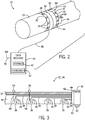
- FIG. 2 is an illustration of an embodiment of the welding system 10 having a temperature sensor belt.
- the workpiece 28 has a joint 30 where joining (e.g., welding) is to be performed.
- a temperature sensor belt 32 is positioned adjacent to the joint 30 to detect one or more temperatures of the workpiece 28 before, during, and/or after the joint 30 is welded.
- the temperature sensor belt 32 may be positioned within one to four inches from the joint 30, in certain embodiments.
- a second temperature sensor belt 34 is positioned adjacent to the joint 30, on an opposite side of the joint 30 relative to the temperature sensor belt 32.
- the temperature sensor belts 32 and 34 are substantially identical. While two temperature sensor belts 32 and 34 are illustrated, the welding system 10 may include 1, 2, 3, 4, 5, or more temperature sensor belts.
- two or more temperature sensor belts may be adjacent to one another on one side of the joint 30.
- the temperature sensor belts 32 and 34 may be formed from any suitable material that enables the belts 32 and 34 to wrap around (e.g., surround the external surface of) the workpiece 28, such as an elastic material, a flexible material, a heat resistant material, a cloth, a material having hook and loop fasteners (e.g., VelcroTM), and so forth. While the workpiece 28 has a circular external surface in the illustrated embodiment, in other embodiments, the workpiece 28 may have an external surface that is triangular, square, rectangular, flat, or any other standard or non-standard shape of exterior surface.
- two or more temperature sensor belts 32 and 34 may be connected in any suitable configuration to enable temperature measurements of any shape joint 30. For example, two or more temperature sensor belts 32 and 34 may be connected together serially.
- the temperature sensor belts 32, 34 include temperature sensors 36 attached to, installed in, installed on, and/or otherwise coupled thereto.
- the temperature sensors 36 may be attached to the temperature sensor belts 32, 34 so that the temperature sensors 36 contact the surface of the workpiece 28 (e.g., exterior surface, interior surface, or the temperature sensors may detect a temperature via conduction with the temperature sensor belts 32, 34.
- the temperature sensors 36 may detect a temperature without contacting the surface of the workpiece 28.
- the temperature sensors 36 may be any suitable devices that can provide indications that correspond to temperatures.
- one or more of the temperature sensors 36 may be a thermocouple, a bimetallic switch, a resistance temperature detector (RTD), a thermistor, a wax motor (e.g., actuator device suitable for converting thermal-to-mechanical energy via phase change behavior of waxes), and/or an infrared sensor.
- the indication representative of a temperature of the workpiece 28 may include a signal, such as a voltage signal, a current signal, a wireless, signal, a magnetic signal and so on.
- the indication may additionally or alternatively be a data packet or packets, or other indications that may include numbers, text, or a combination thereof.
- the temperature sensors 36 are configured to communicate with another device by using a cable 38. Moreover, in other embodiments, the temperature sensors 36 may provide indications (e.g., data or signals) that correspond to temperatures using wired and/or wireless communication.
- a data receiver 40 may receive the indications from the temperature sensors 36 via the cable 38.
- the data receiver 40 may be a stand alone device, or may be incorporated into a computer system, welding power supply (e.g., the power supply 12 illustrated in FIG. 1 ), or any suitable device, including cloud-based devices (e.g., servers accessible as cloud-based services).
- the data receiver 40 may include one or more storage devices 42 for storing the indications from the temperature sensors 36.
- the one or more storage devices 42 may include ROM, flash memory, a hard drive, or any other suitable optical, magnetic, or solid-state storage medium, or a combination thereof.
- the one or more storage devices 42 may store data (e.g., indications from the temperature sensors 36, temperature data, etc.), instructions (e.g., software or firmware for determining temperatures, etc.), and any other suitable data.
- the data receiver 40 may include one or more processors 43 for processing the indications from the temperature sensors 36, such as for converting indications to temperature data.
- the data receiver 40 may receive the indications from the temperature sensors 36 and may provide the indications to another device, without storing the indications.
- the data receiver 40 may function as a pass-through device where the indications from the temperature sensors 36 are provided to a network device, a storage device, a server, and/or any other suitable device for storage and/or processing (e.g., an Internet server, Cloud storage, etc.).
- the temperature sensor belts 32, 34 may also include one or more temperature sensors 44 configured to communicate using wireless signals 46.
- the data receiver 40 may be configured to receive wireless signals 48 for storing and/or processing the indications from the wireless temperature sensor 44.
- the wireless temperature sensor 44 may be a thermocouple, a bimetallic switch, a resistance temperature detector (RTD), a thermistor, a wax motor, and/or an infrared sensor, with a wireless module (e.g., BluetoothTM module, WiFi module, mesh networking module) suitable for transmitting wireless signals.
- the wireless temperature sensor 44 may also communicate using wired communication.
- the workpiece 28 may be configured to rotate during a welding operation.
- the wireless temperature sensor 44 may be used so that temperature sensor leads do not wrap around the workpiece 28.
- the belts 32, 34 may be partially disposed onto the workpiece 28. For example, only a portion of the belts 32, 34 may be positioned to take temperature readings of the workpiece 28. Because of the flexibility of the belts 32, 34, the belts 32, 34 may be positioned on the workpiece 28 to provide for curved belts 32, 34 (e.g., s-curves or any other curves), and/or to encircle certain joints in use. Further, in workpieces 28 of larger sizes, the belts 32, 34 may not completely surround the larger workpiece 28 but may only take readings of certain portions of the workpiece 28.
- the belts 32, 34 may be additionally disposed on inside portions of the workpiece 28, such as inside of a pipe.
- the belts 32, 34 may include magnetic layers or attachment points (e.g., magnets disposed on the belts 32, 34) suitable for magnetically attaching the belts 32, 34 onto the workpiece 28.
- the belts 32, 34 may be clamped inside or outside portions of the workpiece 28.
- the temperature sensor belts 32, 34 may also include a wireless transmitter/receiver system 50.
- the wireless system 50 may receive indications that correspond to temperatures from the temperature sensors 36 and 44 coupled to the temperature sensor belts 32, 34.
- the wireless system 50 may be electrically coupled to the temperature sensors 36, 44 of the temperature sensor belts 32, 34 and/or receive wireless signals from the wireless temperature sensors 44 of the temperature sensor belts 32, 34.
- the wireless system 50 may include a battery to power the temperature sensors 36, 44.
- the wireless system 50 provides wireless signals 52 that may be received by the data receiver 40.
- temperatures of the workpiece 28 may be detected and/or monitored. Accordingly, a quality of a weld performed on the joint 30 may be determined and/or controlled.
- FIG. 3 is a cross-sectional view of an example of a temperature sensor belt, not belonging to the invention.
- the temperature sensor belts 32, 34 may include an insulative layer 54.
- the insulative layer 54 is configured to thermally insulate one or more sides of the temperature sensors 36, 44 that are not arranged to contact the workpiece 28, such as to insulate the temperature sensors 36, 44 from direct heat produced by a welding operation.
- the insulative layer 54 may be configured to protect the temperature sensors 36, 44 and/or improve the accuracy of detected temperatures.
- the insulative layer 54 may be formed from any suitable material, such as a polymer based material, a cloth, a fabric, and so forth.
- connectors 56 are disposed in the insulative layer 54 to facilitate electrically coupling temperature sensor leads 58 to the temperature sensors 36. Furthermore, the temperature sensor leads 58 are disposed in the insulative layer 54.
- the temperature sensor belts 32, 34 may include a connector 60 that couples the temperature sensor leads 58 to the wireless system 50. As illustrated, the wireless system 50 may communicate wirelessly using the wireless signals 52 and/or the wireless system 50 may communicate using a wired connection coupled to the wireless system 50 via a connector 62. Accordingly, the leads 58 may be communicatively coupled to an external device, such as to the power supply 12.
- the connector 62 may be a 90° connector to facilitate coupling to the external device. In other embodiments, the connector 62 may be angled at any angle, including parallel to the belts 32, 34.
- the temperature sensor belts 32, 34 may include a support layer 64 configured to provide support to the insulative layer 54 and/or the temperature sensors 36, 44.
- the support layer 64 may include a protective material to protect the insulative layer 54 and/or the temperature sensors 36, 44 from abrasion and impact with welding spatter and/or other objects.
- the support layer 64 may be formed from any suitable material, such as a flexible material, a metal, a metal alloy, a heat resistive material, a polymeric material, and so forth.
- the support layer 64 may be formed from a braided metal (e.g., braided copper).
- the temperature sensor belts 32, 34 may also include indicators 66 which may be disposed on a side of the support layer 64 opposite the temperature sensors 36, and that may receive an indication (e.g., visual and/or audio indication) representative of the temperature of the workpiece 28 from the temperature sensors 36 via leads 68.
- the visual indicators 66 may provide a visual indication of a temperature or feedback relating to a temperature, such as via a digital display.
- the visual indicators 66 may each include one or more light-emitting diodes (LEDs) configured to illuminate when a threshold temperature is passed (e.g., when the temperature is greater than 300 degrees Celsius, when the temperature is less than 350 degrees Celsius, etc.).
- LEDs light-emitting diodes
- the threshold temperature may be set by an operator, such as using the data receiver 40, the wireless system 50, via setting on the sensors 36, 44 (e.g., jumper settings) and so forth.
- the indication devices 66 may also be disposed on the power supply 12. Accordingly, the power supply 12 may additionally or alternatively indicate to the operator 18 if the operation on the workpiece 28 is proceeding as desired (e.g., at the desired temperature).
- FIG. 3 shows two layers 64 and 54
- the belts 32, 34 may include other layers 64, 54.
- additional protective layers 64 may be disposed on top of layer 54, below layer 54, or between layer 54.
- multiple insulation layers 54 may be used.
- Multiple layers 54 may be stacked on top of each other, and similarly, multiple layers 64 may be stacked on top of each other.
- various combinations of layers 54 and 64 may be used.
- the insulation layer 54 may only partially insulate the sensors 36.
- the layer 54 may be disposed to partially surround the sensors 36 rather than completely surround the sensors 36. In other example, the layer 54 may only insulate a portion of the sensors 36, such a side of the sensors 36 or a portion of the side of the sensor 36. It is also to be noted that multiple layers 64 and 54 may each include different materials. For example, one protective layer 64 may include metal while another protective layer 64 may include KevlarTM. Likewise, one layer 54 may include NomexTM while another layer 54 may include a polymeric composition.
- the temperature sensors 36, 44 may be positioned at predetermined locations along the temperature sensor belts 32, 34.
- the temperature sensors 36, 44 may be positioned (e.g., evenly spaced) at intervals such as every 15, 30, 45, 60 cm, or any other distance.
- a position of the temperature sensors 36, 44 may be adjustable.
- the temperature sensors 36, 44 may be positioned to be located around a circular pipe at intervals such as every 10, 30, or 90 degrees (e.g., 12:00, 3:00, 6:00, 9:00 positions as viewed on a clock face).
- the temperature sensor belts 32, 34 may be manufactured for a specific sized pipe, or the temperature sensor belts 32, 34 may be adjustable.
- the temperature sensor belts 32, 34 may include a portion with hook and loop fasteners (e.g., VelcroTM portion), a locking portion, and/or a buckle portion used to adjust the size of the temperature sensor belts 32, 34.
- FIG. 4 is a perspective view of another example of the temperature sensor belt not belonging to the invention, with a housing for a temperature sensor.
- the temperature sensor belt 32 includes a band 70, which may be formed from a support material, a flexible material, a metal, or a high temperature polymer, for example.
- a temperature sensor housing 72 may be formed in (e.g., stamped, molded, brazed, riveted, etc.) the band 70 so that the temperature sensors 36, 44 may be inserted into and/or removed from the housing 72 (e.g., removable and replaceable sensor embodiments).
- the housing 72 may be formed to enable the temperature sensors 36, 44 to directly contact the workpiece 28 when the temperature sensor belts 32, 34 are attached to the workpiece 28, or the temperature sensors 36, 44 may detect temperatures conducted through the housing 72. That is, the housing 72 may be positioned, in use, to contact the workpiece 28. In certain embodiments, the housing 72 may enable detection of temperatures without the temperature sensors 36, 44 contacting the workpiece 28 (e.g., in embodiments where the sensors 36, 44 include an infrared sensor suitable for detecting temperature through infrared radiation transmitted from the workpiece 28).
- the housing 72 may include one or more openings disposed on a wall of the housing 72 abutting the workpiece 28 when in use, to enable the passage of infrared radiation into the sensors 36, 44. Furthermore, the housing 72 may function as a support layer and/or an insulative layer. In certain embodiments, the housing 72 may be manufactured to include a support layer separate from an insulative layer. Using the temperature sensor belts 32, 34, temperatures of the workpiece 28 may be detected and/or monitored. Accordingly, a quality of a weld performed on the joint 30 may be determined and/or controlled.
- FIG. 5 is a perspective view of an embodiment of the temperature sensor belts 32, 34 with a housing for a temperature sensor.
- the temperature sensor belts 32, 34 may include a strap 74 (e.g., support material, flexible material), such as an elastic strap, a strap having hook and loop fasteners (e.g., VelcroTM strap), a cloth strap, or any other suitable strap.
- Temperature sensor housings 76 are threaded onto the strap 74 and configured to hold temperature sensors 36, 44.
- the sensor housings 76 due at least in part to the threading technique used to mount the housings 76 onto the strap 74, may be repositionable housings 76.
- the welding operator 18 may reposition the housings 76 closer or further apart depending on the desired application (e.g., welding, cutting, grinding, induction heating, testing, and so forth).
- the housings 76 may also be removed from or added to the strap 74, as desired, to incorporate more or less temperature sensor readings for a particular application.
- FIG. 6 is a perspective view of an embodiment of the housing 76 of FIG. 5 having the temperature sensors 36, 44 inserted therein.
- the housing 76 includes openings 78 that enable the strap 74 to be threaded therethrough.
- the housing 76 may be formed from a metal (e.g., via stamping, CNC machining, molding) or a high temperature polymer (e.g., via molding).
- the housing 76 may be formed to enable the temperature sensors 36, 44 to directly contact the workpiece 28 through an opening 80 when the temperature sensor belts 32, 34 are attached to the workpiece 28.
- the temperature sensors 36, 44 may detect temperatures conducted through the housing 76 (e.g., through thermal conduction or thermal convection) or optically transmitted through the opening 80 (e.g., through infrared radiation) in the housing 76.
- the housing 76 may function as a support layer and/or an insulative layer. That is, by cradling the sensor 36, 44 as illustrated, the housing 76 may support the sensor 36, 44 and may also insulate the sensor 36, 44.
- the housing 76 may be manufactured to include a support layer separate from an insulative layer. Using the temperature sensor belts 32, 34, temperatures of the workpiece 28 may be detected and/or monitored. Accordingly, a quality of a weld performed on the joint 30 may be determined and/or controlled. Specifically, temperatures that the workpiece 28 is exposed to during the welding operation may be determined.
Landscapes
- Physics & Mathematics (AREA)
- General Physics & Mathematics (AREA)
- Engineering & Computer Science (AREA)
- Mechanical Engineering (AREA)
- General Engineering & Computer Science (AREA)
- Spectroscopy & Molecular Physics (AREA)
- Lining Or Joining Of Plastics Or The Like (AREA)
- Measuring Temperature Or Quantity Of Heat (AREA)
- Health & Medical Sciences (AREA)
- Life Sciences & Earth Sciences (AREA)
- Chemical & Material Sciences (AREA)
- Analytical Chemistry (AREA)
- Biochemistry (AREA)
- General Health & Medical Sciences (AREA)
- Immunology (AREA)
- Pathology (AREA)
Description
- The document
CN 202 255 656 U relates to a thermoelectric couple fixing tooling device for thermal treatment of a barrel. The device is covered on the barrel and fixes a thermoelectric couple on the barrel. The device comprising a steel belt locker, a steel belt and a plurality of thermoelectric couple clamp blocks, wherein two ends of the steel belt are connected with the steel belt locker, so as to form a ring-shaped structure. The plurality of thermoelectric couple clamp blocks are clamped between the steel belt and the barrel. - The invention relates generally to temperature sensors and, more particularly, to a temperature sensor belt that may be used during a welding operation.
- Welding is a process that has increasingly become utilized in various industries and applications. Such processes may be automated in certain contexts, although a large number of applications continue to exist for manual welding operations. In both cases, such welding operations rely on a variety of types of equipment to ensure the supply of welding consumables (e.g., wire feed, shielding gas, etc.) is provided to the weld in appropriate amounts at the desired time.
- Welding operations are performed on a variety of different materials. For example, a workpiece may be formed from a carbon steel or a corrosion resistant alloy, such as stainless steel. Certain workpieces may be sensitive to heat, such as heat produced during a welding operation. Accordingly, a quality of a weld on a workpiece may depend on temperatures that the workpiece is exposed to during the welding operation. Unfortunately, it may be difficult to detect the temperature of a workpiece near a joint while a welding operation is occurring on the joint. Thus, it may be difficult to determine temperatures that a workpiece is exposed to during the welding operation.
- The present invention relates to a temperature sensor belt as defined by independent claim 1, wherein further developments of the inventive temperature sensor belt are defined by the sub-claims, respectively.
- In one embodiment, a temperature sensor belt includes at least one temperature sensor. The temperature sensor is configured to provide an indication representative of a temperature of a workpiece. The temperature sensor belt also includes a support material disposed over the at least one temperature sensor. The support material is configured to support the at least one temperature sensors on the sensor belt. The temperature sensor belt also includes an insulative material at least partially surrounding the at least one temperature sensor, wherein the insulative material is configured to thermally insulate the at least one temperature sensor.
- In another embodiment, a temperature sensor belt includes a plurality of temperature sensors. Each temperature sensor is configured to provide an indication representative of a temperature. The temperature sensor belt also includes a first layer having an insulative material, wherein the first layer at least partially thermally insulates the plurality of temperature sensors. Additionally, the temperature sensor belt includes a second layer having a protective material, wherein the first layer is disposed between the plurality of temperature sensors and the second layer.
- In a further embodiment, a temperature sensor belt includes one or more temperature sensors configured to detect temperatures on a surface of a workpiece. The temperature sensor belt also includes a strap having a support material disposed over the one or more temperature sensors. The support material is configured to support the one or more temperature sensors.
- These and other features, aspects, and advantages of the present invention will become better understood when the following detailed description is read with reference to the accompanying drawings in which like characters represent like parts throughout the drawings, wherein:
-
FIG. 1 is an illustration of an embodiment of a welding system including a workpiece that may be formed from a carbon steel or a corrosion resistant alloy, in accordance with aspects of the present disclosure; -
FIG. 2 is an illustration of an embodiment of a welding system having a temperature sensor belt, in accordance with aspects of the present disclosure; -
FIG. 3 is a cross-sectional view of an example of a temperature sensor belt, not belonging to the invention; -
FIG. 4 is a perspective view of an example of a temperature sensor belt with a housing for a temperature sensor, not belonging to the invention; -
FIG. 5 is a perspective view of another embodiment of a temperature sensor belt with a housing for a temperature sensor, in accordance with aspects of the present disclosure; and -
FIG. 6 is a perspective view of an embodiment of the housing ofFIG. 5 having a temperature sensor inserted therein, in accordance with aspects of the present disclosure. - Embodiments of the present invention may be used in any application where one or more temperatures may be detected. For example,
FIG. 1 illustrates anarc welding system 10. As depicted, thearc welding system 10 may include apower supply 12 that generates and supplies welding power to anelectrode 14 via aconduit 16. In thearc welding system 10, a direct current (DC) or alternating current (AC) may be used along with the consumable or non-consumableelectrode 14 to deliver current to the point of welding. In such awelding system 10, anoperator 18 may control the location and operation of theelectrode 14 by positioning theelectrode 14 and triggering the starting and stopping of the current flow. As illustrated, ahelmet assembly 20 is worn by thewelding operator 18. Thehelmet assembly 20 includes ahelmet shell 22 and alens assembly 24 that may be darkened to prevent or limit exposure to the light generated by awelding arc 26. - When the
operator 18 begins the welding operation (or other operation such as plasma cutting) by applying power from thepower supply 12 to theelectrode 14, thewelding arc 26 is developed between theelectrode 14 and aworkpiece 28, such as the illustrated pipe. Theworkpiece 28 may be formed from a carbon steel or a corrosion resistant alloy, such as stainless steel, or other metals and alloys (e.g., aluminum, titanium, zirconium, niobium, tantalum, nickel alloys). Non-metal (e.g., plastic, polymeric, rubber)workpieces 28 may also be welded or otherwise joined, for example, by stir welding. - Generally, the techniques described herein enable certain operations (e.g., welding, cutting, grinding, induction heating, testing) to be performed on the
workpiece 28 by applying power supplied by thepower supply 12. Theworkpiece 28 may be disposed in an industrial facility (e.g., industrial plant, shipyard) but may also be disposed in a residential facility, such as a garage or a home. Theworkpiece 28 may include tubular pieces (e.g., pipe), flat sheeting (e.g., metal or plastic sheets and plates), angled workpieces 28 (e.g., angle iron) or any other piece that may be welded, cut, ground, induction heated, or tested, for example, by using power delivered via thepower supply 12. - The
electrode 14 and theconduit 16 thus deliver current and voltage sufficient to create thewelding arc 26 between theelectrode 14 and thework piece 28. Thewelding arc 26 melts the metal (the base material and any filler material added) at the point of welding between theelectrode 14 and thework piece 28, thereby providing a joint when the metal cools. Thewelding system 10 may be configured to form a weld joint by any suitable technique, including shielded metal arc welding (SMAW) (i.e., stick welding), gas tungsten arc welding (GTAW), gas metal arc welding (GMAW), flux-cored arc welding (FCAW), metal inert gas welding (MIG), tungsten inert gas welding (TIG), gas welding (e.g., oxyacetylene welding), sub-arc welding (SAW), and/or resistance welding. As may be appreciated, shielding gas may be used in certain applications, such as GTAW, GMAW, and FCAW, for example. Waveforms used during welding may include regulated metal deposition (RMD) type waveforms, among others, surface tension transfer (STT), cold metal transfer (CMT). - As described below, heat applied to the
workpiece 28 may be detected (e.g., sensed) using a temperature sensor belt. By using the temperature sensor belt, temperatures of theworkpiece 28 near a welding application may be detected and/or monitored to determine a quality of a welding operation and/or to control temperature of a welding operation being performed. As may be appreciated, such a temperature sensor belt may be used in any application where temperature detection is desired, such as welding, cutting, grinding, induction heating, testing, and so forth. -
FIG. 2 is an illustration of an embodiment of thewelding system 10 having a temperature sensor belt. Theworkpiece 28 has a joint 30 where joining (e.g., welding) is to be performed. Atemperature sensor belt 32 is positioned adjacent to thejoint 30 to detect one or more temperatures of theworkpiece 28 before, during, and/or after thejoint 30 is welded. For example, thetemperature sensor belt 32 may be positioned within one to four inches from thejoint 30, in certain embodiments. A secondtemperature sensor belt 34 is positioned adjacent to thejoint 30, on an opposite side of thejoint 30 relative to thetemperature sensor belt 32. As may be appreciated, thetemperature sensor belts temperature sensor belts welding system 10 may include 1, 2, 3, 4, 5, or more temperature sensor belts. Moreover, in some embodiments, two or more temperature sensor belts may be adjacent to one another on one side of the joint 30. Thetemperature sensor belts belts workpiece 28, such as an elastic material, a flexible material, a heat resistant material, a cloth, a material having hook and loop fasteners (e.g., Velcro™), and so forth. While theworkpiece 28 has a circular external surface in the illustrated embodiment, in other embodiments, theworkpiece 28 may have an external surface that is triangular, square, rectangular, flat, or any other standard or non-standard shape of exterior surface. As may be appreciated, two or moretemperature sensor belts temperature sensor belts - The
temperature sensor belts temperature sensors 36 attached to, installed in, installed on, and/or otherwise coupled thereto. Thetemperature sensors 36 may be attached to thetemperature sensor belts temperature sensors 36 contact the surface of the workpiece 28 (e.g., exterior surface, interior surface, or the temperature sensors may detect a temperature via conduction with thetemperature sensor belts temperature sensors 36 may detect a temperature without contacting the surface of theworkpiece 28. Thetemperature sensors 36 may be any suitable devices that can provide indications that correspond to temperatures. For example, one or more of thetemperature sensors 36 may be a thermocouple, a bimetallic switch, a resistance temperature detector (RTD), a thermistor, a wax motor (e.g., actuator device suitable for converting thermal-to-mechanical energy via phase change behavior of waxes), and/or an infrared sensor. The indication representative of a temperature of theworkpiece 28 may include a signal, such as a voltage signal, a current signal, a wireless, signal, a magnetic signal and so on. The indication may additionally or alternatively be a data packet or packets, or other indications that may include numbers, text, or a combination thereof. - As illustrated, the
temperature sensors 36 are configured to communicate with another device by using acable 38. Moreover, in other embodiments, thetemperature sensors 36 may provide indications (e.g., data or signals) that correspond to temperatures using wired and/or wireless communication. Adata receiver 40 may receive the indications from thetemperature sensors 36 via thecable 38. Thedata receiver 40 may be a stand alone device, or may be incorporated into a computer system, welding power supply (e.g., thepower supply 12 illustrated inFIG. 1 ), or any suitable device, including cloud-based devices (e.g., servers accessible as cloud-based services). In certain embodiments, thedata receiver 40 may include one ormore storage devices 42 for storing the indications from thetemperature sensors 36. The one or more storage devices 42 (e.g., nonvolatile storage) may include ROM, flash memory, a hard drive, or any other suitable optical, magnetic, or solid-state storage medium, or a combination thereof. The one ormore storage devices 42 may store data (e.g., indications from thetemperature sensors 36, temperature data, etc.), instructions (e.g., software or firmware for determining temperatures, etc.), and any other suitable data. In certain embodiments, thedata receiver 40 may include one ormore processors 43 for processing the indications from thetemperature sensors 36, such as for converting indications to temperature data. Moreover, in some embodiments, thedata receiver 40 may receive the indications from thetemperature sensors 36 and may provide the indications to another device, without storing the indications. For example, thedata receiver 40 may function as a pass-through device where the indications from thetemperature sensors 36 are provided to a network device, a storage device, a server, and/or any other suitable device for storage and/or processing (e.g., an Internet server, Cloud storage, etc.). - Furthermore, in certain embodiments, the
temperature sensor belts data receiver 40 may be configured to receivewireless signals 48 for storing and/or processing the indications from the wireless temperature sensor 44. As may be appreciated, the wireless temperature sensor 44 may be a thermocouple, a bimetallic switch, a resistance temperature detector (RTD), a thermistor, a wax motor, and/or an infrared sensor, with a wireless module (e.g., Bluetooth™ module, WiFi module, mesh networking module) suitable for transmitting wireless signals. Furthermore, in some embodiments, the wireless temperature sensor 44 may also communicate using wired communication. In certain embodiments, theworkpiece 28 may be configured to rotate during a welding operation. In such embodiments, the wireless temperature sensor 44 may be used so that temperature sensor leads do not wrap around theworkpiece 28. Thebelts workpiece 28. For example, only a portion of thebelts workpiece 28. Because of the flexibility of thebelts belts workpiece 28 to provide forcurved belts 32, 34 (e.g., s-curves or any other curves), and/or to encircle certain joints in use. Further, inworkpieces 28 of larger sizes, thebelts larger workpiece 28 but may only take readings of certain portions of theworkpiece 28. Thebelts workpiece 28, such as inside of a pipe. For example, thebelts belts 32, 34) suitable for magnetically attaching thebelts workpiece 28. Likewise, thebelts workpiece 28. - The
temperature sensor belts receiver system 50. Thewireless system 50 may receive indications that correspond to temperatures from thetemperature sensors 36 and 44 coupled to thetemperature sensor belts wireless system 50 may be electrically coupled to thetemperature sensors 36, 44 of thetemperature sensor belts temperature sensor belts wireless system 50 may include a battery to power thetemperature sensors 36, 44. Thewireless system 50 provides wireless signals 52 that may be received by thedata receiver 40. As may be appreciated, by using thetemperature sensor belts workpiece 28 may be detected and/or monitored. Accordingly, a quality of a weld performed on the joint 30 may be determined and/or controlled. -
FIG. 3 is a cross-sectional view of an example of a temperature sensor belt, not belonging to the invention. Thetemperature sensor belts insulative layer 54. Theinsulative layer 54 is configured to thermally insulate one or more sides of thetemperature sensors 36, 44 that are not arranged to contact theworkpiece 28, such as to insulate thetemperature sensors 36, 44 from direct heat produced by a welding operation. In certain embodiments, theinsulative layer 54 may be configured to protect thetemperature sensors 36, 44 and/or improve the accuracy of detected temperatures. Theinsulative layer 54 may be formed from any suitable material, such as a polymer based material, a cloth, a fabric, and so forth. In the illustrated embodiment,connectors 56 are disposed in theinsulative layer 54 to facilitate electrically coupling temperature sensor leads 58 to thetemperature sensors 36. Furthermore, the temperature sensor leads 58 are disposed in theinsulative layer 54. Thetemperature sensor belts connector 60 that couples the temperature sensor leads 58 to thewireless system 50. As illustrated, thewireless system 50 may communicate wirelessly using the wireless signals 52 and/or thewireless system 50 may communicate using a wired connection coupled to thewireless system 50 via aconnector 62. Accordingly, theleads 58 may be communicatively coupled to an external device, such as to thepower supply 12. In one embodiment, theconnector 62 may be a 90° connector to facilitate coupling to the external device. In other embodiments, theconnector 62 may be angled at any angle, including parallel to thebelts - The
temperature sensor belts support layer 64 configured to provide support to theinsulative layer 54 and/or thetemperature sensors 36, 44. In certain embodiments, thesupport layer 64 may include a protective material to protect theinsulative layer 54 and/or thetemperature sensors 36, 44 from abrasion and impact with welding spatter and/or other objects. Thesupport layer 64 may be formed from any suitable material, such as a flexible material, a metal, a metal alloy, a heat resistive material, a polymeric material, and so forth. For example, in certain embodiments, thesupport layer 64 may be formed from a braided metal (e.g., braided copper). Thetemperature sensor belts indicators 66 which may be disposed on a side of thesupport layer 64 opposite thetemperature sensors 36, and that may receive an indication (e.g., visual and/or audio indication) representative of the temperature of the workpiece 28 from thetemperature sensors 36 via leads 68. Thevisual indicators 66 may provide a visual indication of a temperature or feedback relating to a temperature, such as via a digital display. Furthermore, in certain embodiments, thevisual indicators 66 may each include one or more light-emitting diodes (LEDs) configured to illuminate when a threshold temperature is passed (e.g., when the temperature is greater than 300 degrees Celsius, when the temperature is less than 350 degrees Celsius, etc.). As may be appreciated, the threshold temperature may be set by an operator, such as using thedata receiver 40, thewireless system 50, via setting on thesensors 36, 44 (e.g., jumper settings) and so forth. Theindication devices 66 may also be disposed on thepower supply 12. Accordingly, thepower supply 12 may additionally or alternatively indicate to theoperator 18 if the operation on theworkpiece 28 is proceeding as desired (e.g., at the desired temperature). - While
FIG. 3 shows twolayers belts other layers protective layers 64 may be disposed on top oflayer 54, belowlayer 54, or betweenlayer 54. Likewise, multiple insulation layers 54 may be used. For example, in certain embodiments, there could be aninsulation layer 54 followed by aprotective layer 64 followed by anotherinsulation layer 54 followed by anotherprotective layer 64, and so on.Multiple layers 54 may be stacked on top of each other, and similarly,multiple layers 64 may be stacked on top of each other. In short, various combinations oflayers insulation layer 54 may only partially insulate thesensors 36. For example, thelayer 54 may be disposed to partially surround thesensors 36 rather than completely surround thesensors 36. In other example, thelayer 54 may only insulate a portion of thesensors 36, such a side of thesensors 36 or a portion of the side of thesensor 36. It is also to be noted thatmultiple layers protective layer 64 may include metal while anotherprotective layer 64 may include Kevlar™. Likewise, onelayer 54 may include Nomex™ while anotherlayer 54 may include a polymeric composition. - The
temperature sensors 36, 44 may be positioned at predetermined locations along thetemperature sensor belts temperature sensors 36, 44 may be positioned (e.g., evenly spaced) at intervals such as every 15, 30, 45, 60 cm, or any other distance. Furthermore, in some embodiments, a position of thetemperature sensors 36, 44 may be adjustable. Moreover, in certain embodiments, thetemperature sensors 36, 44 may be positioned to be located around a circular pipe at intervals such as every 10, 30, or 90 degrees (e.g., 12:00, 3:00, 6:00, 9:00 positions as viewed on a clock face). Accordingly, thetemperature sensor belts temperature sensor belts temperature sensor belts temperature sensor belts -
FIG. 4 is a perspective view of another example of the temperature sensor belt not belonging to the invention, with a housing for a temperature sensor. Thetemperature sensor belt 32 includes aband 70, which may be formed from a support material, a flexible material, a metal, or a high temperature polymer, for example. Atemperature sensor housing 72 may be formed in (e.g., stamped, molded, brazed, riveted, etc.) theband 70 so that thetemperature sensors 36, 44 may be inserted into and/or removed from the housing 72 (e.g., removable and replaceable sensor embodiments). Thehousing 72 may be formed to enable thetemperature sensors 36, 44 to directly contact theworkpiece 28 when thetemperature sensor belts workpiece 28, or thetemperature sensors 36, 44 may detect temperatures conducted through thehousing 72. That is, thehousing 72 may be positioned, in use, to contact theworkpiece 28. In certain embodiments, thehousing 72 may enable detection of temperatures without thetemperature sensors 36, 44 contacting the workpiece 28 (e.g., in embodiments where thesensors 36, 44 include an infrared sensor suitable for detecting temperature through infrared radiation transmitted from the workpiece 28). Accordingly, ininfrared sensor 36, 44 embodiments, thehousing 72 may include one or more openings disposed on a wall of thehousing 72 abutting theworkpiece 28 when in use, to enable the passage of infrared radiation into thesensors 36, 44. Furthermore, thehousing 72 may function as a support layer and/or an insulative layer. In certain embodiments, thehousing 72 may be manufactured to include a support layer separate from an insulative layer. Using thetemperature sensor belts workpiece 28 may be detected and/or monitored. Accordingly, a quality of a weld performed on the joint 30 may be determined and/or controlled. -
FIG. 5 is a perspective view of an embodiment of thetemperature sensor belts temperature sensor belts Temperature sensor housings 76 are threaded onto the strap 74 and configured to holdtemperature sensors 36, 44. Thesensor housings 76, due at least in part to the threading technique used to mount thehousings 76 onto the strap 74, may berepositionable housings 76. For example, thewelding operator 18 may reposition thehousings 76 closer or further apart depending on the desired application (e.g., welding, cutting, grinding, induction heating, testing, and so forth). Thehousings 76 may also be removed from or added to the strap 74, as desired, to incorporate more or less temperature sensor readings for a particular application. -
FIG. 6 is a perspective view of an embodiment of thehousing 76 ofFIG. 5 having thetemperature sensors 36, 44 inserted therein. As illustrated, thehousing 76 includesopenings 78 that enable the strap 74 to be threaded therethrough. As may be appreciated, thehousing 76 may be formed from a metal (e.g., via stamping, CNC machining, molding) or a high temperature polymer (e.g., via molding). In one embodiment, thehousing 76 may be formed to enable thetemperature sensors 36, 44 to directly contact theworkpiece 28 through an opening 80 when thetemperature sensor belts workpiece 28. In other embodiments, thetemperature sensors 36, 44 may detect temperatures conducted through the housing 76 (e.g., through thermal conduction or thermal convection) or optically transmitted through the opening 80 (e.g., through infrared radiation) in thehousing 76. Furthermore, thehousing 76 may function as a support layer and/or an insulative layer. That is, by cradling thesensor 36, 44 as illustrated, thehousing 76 may support thesensor 36, 44 and may also insulate thesensor 36, 44. In certain embodiments, thehousing 76 may be manufactured to include a support layer separate from an insulative layer. Using thetemperature sensor belts workpiece 28 may be detected and/or monitored. Accordingly, a quality of a weld performed on the joint 30 may be determined and/or controlled. Specifically, temperatures that theworkpiece 28 is exposed to during the welding operation may be determined.
Claims (10)
- A temperature sensor belt (32, 34) comprising:- a plurality of temperature sensors (36, 44) disposed on the sensor belt (32, 34), wherein the plurality of temperature sensors (36, 44) is configured to provide an indication representative of a temperature of a workpiece (28);- a plurality of housings (72, 76) into each of which one temperature sensor of the plurality of temperature sensors (36, 44) is configured to be inserted, wherein each housing of the plurality of housings comprises an insulative material surrounding the plurality of temperature sensors (36, 44) and being configured to thermally insulate the sides of the plurality of temperature sensors (36, 44) that are not arranged to contact the workpiece (28), and- a support material configured to be disposed over the plurality of temperature sensors (36, 44), when the plurality of temperature sensors (36, 44) are inserted into the plurality of housings (72, 76), wherein the support material is configured to support the plurality of temperature sensors (36, 44),wherein the sensor belt (32, 34) comprises a strap (74) of the support material,
wherein each of the plurality of temperature sensors (36, 44) is configured to provide the indication representative of the temperature of the workpiece (28) while a welding operation, cutting operation, grinding operation, or induction heating operation is performed on the workpiece (28), characterized in that the plurality of sensor housings (72, 76) is configured to be threaded onto the strap (74) to mount the plurality of sensor housings (72, 76) repositionably and removably onto the strap (74), wherein each housing of the plurality of sensor housings (72, 76) includes openings (78) that enable the strap to be threaded therethrough, wherein the temperature sensor belt (32, 34) is configured to be connected together serially with at least one additional temperature sensor belt (32, 34). - The temperature sensor belt of claim 1,
wherein the plurality of temperature sensors (36, 44) comprise at least one of an infrared sensor, a thermocouple, a bimetallic switch, a resistance temperature detector (RTD), a thermistor, a wax motor, or a combination thereof. - The temperature sensor belt of claim 1 or 2,
wherein the support material comprises a flexible material. - The temperature sensor belt of one of the preceding claims, comprising a wireless system (50) supported by the support material and communicatively coupled to at least one of the plurality of temperature sensors (36,44), wherein the temperature sensor belt (32, 34) is configured to communicate wirelessly via the wireless system (50).
- The temperature sensor belt of one of the preceding claims,
wherein at least one of the plurality of temperature sensors (36, 44) comprises a wireless temperature sensor (44) configured to wirelessly transmit the indication representative of the temperature of the workpiece (28). - The temperature sensor belt of one of the preceding claims,
wherein the temperature sensor belt (32, 34) has a length configured to at least partially surround an external surface of the workpiece (28). - The temperature sensor belt of claim 6,
wherein the workpiece (28) comprises a pipe. - The temperature sensor belt of one of the preceding claims,
wherein each temperature sensor (36, 44) of the plurality of temperature sensors is unevenly spaced from a respective adjacent temperature sensor (36, 44). - The temperature sensor belt of one of the preceding claims, comprising temperature sensor leads (58) configured to be communicatively coupled to an external device.
- The temperature sensor belt of claim 9,
wherein each temperature sensor (36, 44) of the plurality of temperature sensors is configured to provide the indications to a wireless transmitter.
Applications Claiming Priority (3)
| Application Number | Priority Date | Filing Date | Title |
|---|---|---|---|
| US201361821959P | 2013-05-10 | 2013-05-10 | |
| US14/258,987 US9733130B2 (en) | 2013-05-10 | 2014-04-22 | Temperature sensor belt |
| PCT/US2014/036170 WO2014182526A1 (en) | 2013-05-10 | 2014-04-30 | Temperature sensor belt |
Publications (2)
| Publication Number | Publication Date |
|---|---|
| EP2994729A1 EP2994729A1 (en) | 2016-03-16 |
| EP2994729B1 true EP2994729B1 (en) | 2020-11-11 |
Family
ID=51864766
Family Applications (1)
| Application Number | Title | Priority Date | Filing Date |
|---|---|---|---|
| EP14728745.2A Active EP2994729B1 (en) | 2013-05-10 | 2014-04-30 | Temperature sensor belt |
Country Status (5)
| Country | Link |
|---|---|
| US (2) | US9733130B2 (en) |
| EP (1) | EP2994729B1 (en) |
| CN (2) | CN109974871B (en) |
| CA (1) | CA2902583C (en) |
| WO (1) | WO2014182526A1 (en) |
Families Citing this family (25)
| Publication number | Priority date | Publication date | Assignee | Title |
|---|---|---|---|---|
| US9146172B2 (en) * | 2011-01-03 | 2015-09-29 | Sentinel Hydrosolutions, Llc | Non-invasive thermal dispersion flow meter with chronometric monitor for fluid leak detection |
| FR3041467B1 (en) * | 2015-09-18 | 2022-01-21 | Electricite De France | OBJECT TEMPERATURE MEASUREMENT BELT |
| FR3041429B1 (en) * | 2015-09-18 | 2020-03-27 | Electricite De France | BELT FOR MEASURING PHYSICAL QUANTITIES OF AN OBJECT |
| FR3057664B1 (en) * | 2016-10-19 | 2018-10-19 | Vallourec Oil And Gas France | DEVICE FOR DETERMINING THE ASSEMBLY QUALITY OF THREADED TUBULAR COMPONENTS |
| CN106768691A (en) * | 2016-12-27 | 2017-05-31 | 苏州市宏业灯具设备有限公司 | A kind of steam generator steam leakage detection means |
| US10822995B2 (en) * | 2017-01-17 | 2020-11-03 | The Boeing Company | Flexible band electrical component mounts and methods |
| US20190320244A1 (en) * | 2018-04-16 | 2019-10-17 | Nidec Motor Corporation | Sensor module system |
| US11287330B2 (en) * | 2018-08-14 | 2022-03-29 | Watlow Electric Manufacturing Company | Low profile surface temperature sensor |
| CN110849497B (en) * | 2018-08-20 | 2026-03-27 | 深圳市敏杰电子科技有限公司 | Mounting structure and temperature sensing device of thin-film temperature sensor |
| US10899529B2 (en) * | 2018-12-06 | 2021-01-26 | Integreon Global, Inc. | Thermal insulation box with temperature and humidity sensors |
| US10962272B2 (en) * | 2018-12-06 | 2021-03-30 | Tcp Reliable, Inc. | Thermal insulation box with cooling mechanism |
| CN109752111A (en) * | 2019-01-23 | 2019-05-14 | 杭州嘉诚机械有限公司 | Simple and portable shaft temperature detection module special for speed reducer and detection method |
| DE102019124604A1 (en) * | 2019-09-12 | 2021-03-18 | Endress + Hauser Wetzer Gmbh + Co. Kg | Non-invasive thermometer |
| DE102019124605A1 (en) * | 2019-09-12 | 2021-03-18 | Endress + Hauser Wetzer Gmbh + Co. Kg | Non-invasive thermometer |
| WO2021197921A1 (en) * | 2020-03-30 | 2021-10-07 | Sma Solar Technology Ag | Device for temperature measurement and device for current determination |
| CN115835829B (en) * | 2020-04-02 | 2025-12-12 | 直观外科手术操作公司 | Equipment for recording medical device use, equipment and related systems and methods for recording medical device reprocessing events. |
| US11408778B2 (en) | 2020-07-21 | 2022-08-09 | Apple Inc. | Temperature gradient sensing in portable electronic devices |
| US11771329B2 (en) * | 2020-09-24 | 2023-10-03 | Apple Inc. | Flexible temperature sensing devices for body temperature sensing |
| CN112556865A (en) * | 2020-12-09 | 2021-03-26 | 翟国强 | Water temperature detection device in boiler pipeline |
| WO2022245228A1 (en) * | 2021-05-18 | 2022-11-24 | Bpe Sp. Z O.O. | System for measuring temperature distribution in heating network and method of monitoring heating network |
| DE102021117224A1 (en) | 2021-07-05 | 2023-01-05 | Dr. Ing. H.C. F. Porsche Aktiengesellschaft | Arrangement for measuring the temperature of a battery cell and battery cell with such an arrangement |
| US12575739B2 (en) | 2021-09-21 | 2026-03-17 | Apple Inc. | Distributed sensor network for measurement of biometric parameter |
| US20230265959A1 (en) * | 2022-02-21 | 2023-08-24 | Todd A. Volker | Method and apparatus for reinforcing piping and installing a pipe adapter |
| US12523537B2 (en) | 2023-08-11 | 2026-01-13 | Saudi Arabian Oil Company | Removable sensors system with color indicator for temperature monitoring |
| EP4592659A1 (en) * | 2024-01-29 | 2025-07-30 | Alejandro Torres González | Device for assessing the condition of an insulation |
Citations (2)
| Publication number | Priority date | Publication date | Assignee | Title |
|---|---|---|---|---|
| DE20216024U1 (en) * | 2002-10-17 | 2003-01-16 | Sick AG, 79183 Waldkirch | Fastening device for attaching magnetic or inductive or optical sensors to an object especially a cylindrical object |
| CN202255656U (en) * | 2011-10-11 | 2012-05-30 | 上海电气核电设备有限公司 | Thermocouple fixing tool device for barrel heat treatment |
Family Cites Families (36)
| Publication number | Priority date | Publication date | Assignee | Title |
|---|---|---|---|---|
| US2737050A (en) * | 1953-05-27 | 1956-03-06 | George W Moninger | Thermometer receptacle for attachment to pipes |
| US3983753A (en) * | 1975-09-29 | 1976-10-05 | The United States Of America As Represented By The United States National Aeronautics And Space Administration | Thermistor holder for skin temperature measurements |
| DE3126931A1 (en) | 1981-07-08 | 1983-02-03 | Ultrakust Gerätebau GmbH & Co KG, 8375 Ruhmannsfelden | Retaining device for a temperature sensor |
| DE3225921C2 (en) * | 1982-07-10 | 1985-10-24 | Barlian, Reinhold, Dipl.-Ing.(FH), 6990 Bad Mergentheim | Monitoring device |
| US4569355A (en) * | 1982-05-28 | 1986-02-11 | Hemodynamics Technology, Inc. | Method and apparatus for monitoring and diagnosing peripheral blood flow |
| FR2561382A1 (en) | 1984-03-16 | 1985-09-20 | Chauvin Arnoux Sa | Thermometric sensor for measuring surface temperature |
| US4699519A (en) * | 1985-04-08 | 1987-10-13 | Performance Technology, Inc. | Grain temperature monitor |
| CN2042193U (en) * | 1988-06-15 | 1989-08-02 | 张士洪 | Noninserting platinum thermometer |
| US5255979A (en) * | 1993-02-01 | 1993-10-26 | Ferrari R Keith | Medical temperature probe cover |
| US5980102A (en) * | 1994-06-20 | 1999-11-09 | Columbia Gas Of Ohio | Method for measuring physical characteristics in a pipeline without tapping |
| US5632919A (en) * | 1996-01-25 | 1997-05-27 | T.G.M., Inc. | Temperature controlled insulation system |
| AU1198100A (en) * | 1998-09-23 | 2000-04-10 | Keith Bridger | Physiological sensing device |
| JP2000205967A (en) * | 1999-01-11 | 2000-07-28 | Mitsubishi Heavy Ind Ltd | Thermocouple and structure for attaching the same |
| DE19953654A1 (en) * | 1999-11-08 | 2001-05-23 | Pink Gmbh Vakuumtechnik | Method and device for producing a solder connection |
| AU2363502A (en) * | 2000-10-24 | 2002-05-06 | Saipem Spa | Method and apparatus for welding pipes together |
| ITPN20010003U1 (en) * | 2001-01-25 | 2002-07-25 | Sipa Spa | TEMPERATURE CHANGE DETECTION DEVICE WITH SENSOR HOUSING |
| CA2460290A1 (en) * | 2001-11-01 | 2003-05-08 | Bliss C. Carkhuff | Techniques for monitoring health of vessels containing fluids |
| FR2833346B1 (en) | 2001-12-06 | 2004-07-02 | Jules Richard Instr Sa | DEVICE FOR MEASURING THE TEMPERATURE OF A FLUID IN A CONDUIT AND MONITORING SYSTEM USING SUCH A DEVICE |
| EP1849013B1 (en) * | 2005-02-01 | 2011-11-30 | The Timken Company | Bearing with cage mounted sensors |
| US7299963B2 (en) * | 2005-05-23 | 2007-11-27 | Illinois Tool Works Inc. | Temperature sensor for combustion nailer |
| US20100036277A1 (en) * | 2006-07-06 | 2010-02-11 | John Austin | Animal temperature monitor and monitoring method |
| CN201110789Y (en) * | 2007-11-15 | 2008-09-03 | 王德文 | Steel rail welding temperature measuring and controlling apparatus |
| US20090232183A1 (en) * | 2008-03-13 | 2009-09-17 | General Electric Company | System and method to measure temperature in an electric machine |
| WO2010055455A1 (en) * | 2008-11-11 | 2010-05-20 | Koninklijke Philips Electronics N.V. | Medical device comprising a probe for measuring temperature data in a patient's tissue |
| DE102009003848A1 (en) | 2009-04-29 | 2010-11-04 | Infratec Ag | Temperature control device for monitoring and controlling temperature of server or computer in server cabinet, has temperature sensors arranged at distance relative to each other on flexible, strip-like carrier band |
| CN201464070U (en) * | 2009-09-07 | 2010-05-12 | 瓮福(集团)有限责任公司 | Thermocouple element for measuring temperature on pipeline surface |
| US9494272B2 (en) * | 2009-10-19 | 2016-11-15 | Embedded Energy Technology, Llc | Insulation jacket and insulation jacket system |
| JP5513208B2 (en) * | 2010-03-30 | 2014-06-04 | 高砂熱学工業株式会社 | Piping surface multipoint temperature sensor and flow measurement pipe |
| US11072035B2 (en) * | 2010-05-21 | 2021-07-27 | Illinois Tool Works Inc. | Auxiliary welding heating system |
| WO2011150323A2 (en) * | 2010-05-28 | 2011-12-01 | Neurodx Development, Llc | Real time csf flow measurement system & method |
| KR101005692B1 (en) * | 2010-06-14 | 2011-01-05 | 강성원 | Functional bags |
| CN201772935U (en) * | 2010-07-01 | 2011-03-23 | 卢映桦 | baby temperature monitor |
| CN202271525U (en) * | 2011-07-28 | 2012-06-13 | 广东联塑科技实业有限公司 | Pipe fitting welding machine with temperature control and temperature control system thereof |
| US9341535B2 (en) * | 2012-02-03 | 2016-05-17 | Kulite Semiconductor Products, Inc. | Pressure belt comprising replaceable sensing elements |
| US20140161151A1 (en) * | 2012-12-12 | 2014-06-12 | John Proctor | Line & pipe flexible temperature sensor assembly |
| US20140299595A1 (en) * | 2013-04-09 | 2014-10-09 | Illinois Tool Works Inc. | System and method for holding a temperature probe in an induction heating system |
-
2014
- 2014-04-22 US US14/258,987 patent/US9733130B2/en active Active
- 2014-04-30 CN CN201910163813.5A patent/CN109974871B/en not_active Expired - Fee Related
- 2014-04-30 WO PCT/US2014/036170 patent/WO2014182526A1/en not_active Ceased
- 2014-04-30 CA CA2902583A patent/CA2902583C/en active Active
- 2014-04-30 CN CN201480023562.6A patent/CN105143840B/en not_active Expired - Fee Related
- 2014-04-30 EP EP14728745.2A patent/EP2994729B1/en active Active
-
2017
- 2017-08-03 US US15/668,403 patent/US10458855B2/en active Active
Patent Citations (2)
| Publication number | Priority date | Publication date | Assignee | Title |
|---|---|---|---|---|
| DE20216024U1 (en) * | 2002-10-17 | 2003-01-16 | Sick AG, 79183 Waldkirch | Fastening device for attaching magnetic or inductive or optical sensors to an object especially a cylindrical object |
| CN202255656U (en) * | 2011-10-11 | 2012-05-30 | 上海电气核电设备有限公司 | Thermocouple fixing tool device for barrel heat treatment |
Also Published As
| Publication number | Publication date |
|---|---|
| WO2014182526A1 (en) | 2014-11-13 |
| CA2902583C (en) | 2018-11-06 |
| US10458855B2 (en) | 2019-10-29 |
| CN105143840A (en) | 2015-12-09 |
| CN105143840B (en) | 2019-03-29 |
| CN109974871B (en) | 2021-11-12 |
| CA2902583A1 (en) | 2014-11-13 |
| EP2994729A1 (en) | 2016-03-16 |
| CN109974871A (en) | 2019-07-05 |
| US20140334517A1 (en) | 2014-11-13 |
| US9733130B2 (en) | 2017-08-15 |
| US20170328784A1 (en) | 2017-11-16 |
Similar Documents
| Publication | Publication Date | Title |
|---|---|---|
| US10458855B2 (en) | Temperature sensor belt | |
| US12070821B2 (en) | Welding system for determining a quality of a welding operation | |
| EP3010677B1 (en) | System and method for determining weld travel speed | |
| CA2902580C (en) | Data acquisition using a purge plug | |
| US20160144445A1 (en) | Welding torch with a temperature measurement device | |
| EP2994730B1 (en) | Rotatable temperature sensing device | |
| KR20230103564A (en) | Welding work management system using wire feeder | |
| EP2547484B1 (en) | Capacitor-circuit board interface for welding system components |
Legal Events
| Date | Code | Title | Description |
|---|---|---|---|
| PUAI | Public reference made under article 153(3) epc to a published international application that has entered the european phase |
Free format text: ORIGINAL CODE: 0009012 |
|
| 17P | Request for examination filed |
Effective date: 20150825 |
|
| AK | Designated contracting states |
Kind code of ref document: A1 Designated state(s): AL AT BE BG CH CY CZ DE DK EE ES FI FR GB GR HR HU IE IS IT LI LT LU LV MC MK MT NL NO PL PT RO RS SE SI SK SM TR |
|
| AX | Request for extension of the european patent |
Extension state: BA ME |
|
| DAX | Request for extension of the european patent (deleted) | ||
| STAA | Information on the status of an ep patent application or granted ep patent |
Free format text: STATUS: EXAMINATION IS IN PROGRESS |
|
| 17Q | First examination report despatched |
Effective date: 20170301 |
|
| GRAP | Despatch of communication of intention to grant a patent |
Free format text: ORIGINAL CODE: EPIDOSNIGR1 |
|
| STAA | Information on the status of an ep patent application or granted ep patent |
Free format text: STATUS: GRANT OF PATENT IS INTENDED |
|
| RIC1 | Information provided on ipc code assigned before grant |
Ipc: F27D 21/00 20060101ALI20200508BHEP Ipc: G01K 1/14 20060101AFI20200508BHEP |
|
| INTG | Intention to grant announced |
Effective date: 20200612 |
|
| GRAS | Grant fee paid |
Free format text: ORIGINAL CODE: EPIDOSNIGR3 |
|
| GRAA | (expected) grant |
Free format text: ORIGINAL CODE: 0009210 |
|
| STAA | Information on the status of an ep patent application or granted ep patent |
Free format text: STATUS: THE PATENT HAS BEEN GRANTED |
|
| AK | Designated contracting states |
Kind code of ref document: B1 Designated state(s): AL AT BE BG CH CY CZ DE DK EE ES FI FR GB GR HR HU IE IS IT LI LT LU LV MC MK MT NL NO PL PT RO RS SE SI SK SM TR |
|
| REG | Reference to a national code |
Ref country code: GB Ref legal event code: FG4D |
|
| REG | Reference to a national code |
Ref country code: CH Ref legal event code: EP |
|
| REG | Reference to a national code |
Ref country code: AT Ref legal event code: REF Ref document number: 1333937 Country of ref document: AT Kind code of ref document: T Effective date: 20201115 |
|
| REG | Reference to a national code |
Ref country code: DE Ref legal event code: R096 Ref document number: 602014072251 Country of ref document: DE |
|
| REG | Reference to a national code |
Ref country code: IE Ref legal event code: FG4D |
|
| REG | Reference to a national code |
Ref country code: NL Ref legal event code: MP Effective date: 20201111 |
|
| REG | Reference to a national code |
Ref country code: AT Ref legal event code: MK05 Ref document number: 1333937 Country of ref document: AT Kind code of ref document: T Effective date: 20201111 |
|
| PG25 | Lapsed in a contracting state [announced via postgrant information from national office to epo] |
Ref country code: PT Free format text: LAPSE BECAUSE OF FAILURE TO SUBMIT A TRANSLATION OF THE DESCRIPTION OR TO PAY THE FEE WITHIN THE PRESCRIBED TIME-LIMIT Effective date: 20210311 Ref country code: NO Free format text: LAPSE BECAUSE OF FAILURE TO SUBMIT A TRANSLATION OF THE DESCRIPTION OR TO PAY THE FEE WITHIN THE PRESCRIBED TIME-LIMIT Effective date: 20210211 Ref country code: FI Free format text: LAPSE BECAUSE OF FAILURE TO SUBMIT A TRANSLATION OF THE DESCRIPTION OR TO PAY THE FEE WITHIN THE PRESCRIBED TIME-LIMIT Effective date: 20201111 Ref country code: RS Free format text: LAPSE BECAUSE OF FAILURE TO SUBMIT A TRANSLATION OF THE DESCRIPTION OR TO PAY THE FEE WITHIN THE PRESCRIBED TIME-LIMIT Effective date: 20201111 Ref country code: GR Free format text: LAPSE BECAUSE OF FAILURE TO SUBMIT A TRANSLATION OF THE DESCRIPTION OR TO PAY THE FEE WITHIN THE PRESCRIBED TIME-LIMIT Effective date: 20210212 |
|
| PG25 | Lapsed in a contracting state [announced via postgrant information from national office to epo] |
Ref country code: LV Free format text: LAPSE BECAUSE OF FAILURE TO SUBMIT A TRANSLATION OF THE DESCRIPTION OR TO PAY THE FEE WITHIN THE PRESCRIBED TIME-LIMIT Effective date: 20201111 Ref country code: SE Free format text: LAPSE BECAUSE OF FAILURE TO SUBMIT A TRANSLATION OF THE DESCRIPTION OR TO PAY THE FEE WITHIN THE PRESCRIBED TIME-LIMIT Effective date: 20201111 Ref country code: PL Free format text: LAPSE BECAUSE OF FAILURE TO SUBMIT A TRANSLATION OF THE DESCRIPTION OR TO PAY THE FEE WITHIN THE PRESCRIBED TIME-LIMIT Effective date: 20201111 Ref country code: IS Free format text: LAPSE BECAUSE OF FAILURE TO SUBMIT A TRANSLATION OF THE DESCRIPTION OR TO PAY THE FEE WITHIN THE PRESCRIBED TIME-LIMIT Effective date: 20210311 Ref country code: AT Free format text: LAPSE BECAUSE OF FAILURE TO SUBMIT A TRANSLATION OF THE DESCRIPTION OR TO PAY THE FEE WITHIN THE PRESCRIBED TIME-LIMIT Effective date: 20201111 Ref country code: BG Free format text: LAPSE BECAUSE OF FAILURE TO SUBMIT A TRANSLATION OF THE DESCRIPTION OR TO PAY THE FEE WITHIN THE PRESCRIBED TIME-LIMIT Effective date: 20210211 |
|
| REG | Reference to a national code |
Ref country code: LT Ref legal event code: MG9D |
|
| PG25 | Lapsed in a contracting state [announced via postgrant information from national office to epo] |
Ref country code: HR Free format text: LAPSE BECAUSE OF FAILURE TO SUBMIT A TRANSLATION OF THE DESCRIPTION OR TO PAY THE FEE WITHIN THE PRESCRIBED TIME-LIMIT Effective date: 20201111 |
|
| PG25 | Lapsed in a contracting state [announced via postgrant information from national office to epo] |
Ref country code: SK Free format text: LAPSE BECAUSE OF FAILURE TO SUBMIT A TRANSLATION OF THE DESCRIPTION OR TO PAY THE FEE WITHIN THE PRESCRIBED TIME-LIMIT Effective date: 20201111 Ref country code: RO Free format text: LAPSE BECAUSE OF FAILURE TO SUBMIT A TRANSLATION OF THE DESCRIPTION OR TO PAY THE FEE WITHIN THE PRESCRIBED TIME-LIMIT Effective date: 20201111 Ref country code: LT Free format text: LAPSE BECAUSE OF FAILURE TO SUBMIT A TRANSLATION OF THE DESCRIPTION OR TO PAY THE FEE WITHIN THE PRESCRIBED TIME-LIMIT Effective date: 20201111 Ref country code: CZ Free format text: LAPSE BECAUSE OF FAILURE TO SUBMIT A TRANSLATION OF THE DESCRIPTION OR TO PAY THE FEE WITHIN THE PRESCRIBED TIME-LIMIT Effective date: 20201111 Ref country code: EE Free format text: LAPSE BECAUSE OF FAILURE TO SUBMIT A TRANSLATION OF THE DESCRIPTION OR TO PAY THE FEE WITHIN THE PRESCRIBED TIME-LIMIT Effective date: 20201111 Ref country code: SM Free format text: LAPSE BECAUSE OF FAILURE TO SUBMIT A TRANSLATION OF THE DESCRIPTION OR TO PAY THE FEE WITHIN THE PRESCRIBED TIME-LIMIT Effective date: 20201111 |
|
| REG | Reference to a national code |
Ref country code: DE Ref legal event code: R097 Ref document number: 602014072251 Country of ref document: DE |
|
| PG25 | Lapsed in a contracting state [announced via postgrant information from national office to epo] |
Ref country code: DK Free format text: LAPSE BECAUSE OF FAILURE TO SUBMIT A TRANSLATION OF THE DESCRIPTION OR TO PAY THE FEE WITHIN THE PRESCRIBED TIME-LIMIT Effective date: 20201111 |
|
| PLBE | No opposition filed within time limit |
Free format text: ORIGINAL CODE: 0009261 |
|
| STAA | Information on the status of an ep patent application or granted ep patent |
Free format text: STATUS: NO OPPOSITION FILED WITHIN TIME LIMIT |
|
| 26N | No opposition filed |
Effective date: 20210812 |
|
| PG25 | Lapsed in a contracting state [announced via postgrant information from national office to epo] |
Ref country code: AL Free format text: LAPSE BECAUSE OF FAILURE TO SUBMIT A TRANSLATION OF THE DESCRIPTION OR TO PAY THE FEE WITHIN THE PRESCRIBED TIME-LIMIT Effective date: 20201111 Ref country code: NL Free format text: LAPSE BECAUSE OF FAILURE TO SUBMIT A TRANSLATION OF THE DESCRIPTION OR TO PAY THE FEE WITHIN THE PRESCRIBED TIME-LIMIT Effective date: 20201111 |
|
| PG25 | Lapsed in a contracting state [announced via postgrant information from national office to epo] |
Ref country code: SI Free format text: LAPSE BECAUSE OF FAILURE TO SUBMIT A TRANSLATION OF THE DESCRIPTION OR TO PAY THE FEE WITHIN THE PRESCRIBED TIME-LIMIT Effective date: 20201111 Ref country code: MC Free format text: LAPSE BECAUSE OF FAILURE TO SUBMIT A TRANSLATION OF THE DESCRIPTION OR TO PAY THE FEE WITHIN THE PRESCRIBED TIME-LIMIT Effective date: 20201111 Ref country code: ES Free format text: LAPSE BECAUSE OF FAILURE TO SUBMIT A TRANSLATION OF THE DESCRIPTION OR TO PAY THE FEE WITHIN THE PRESCRIBED TIME-LIMIT Effective date: 20201111 |
|
| GBPC | Gb: european patent ceased through non-payment of renewal fee |
Effective date: 20210430 |
|
| PG25 | Lapsed in a contracting state [announced via postgrant information from national office to epo] |
Ref country code: LU Free format text: LAPSE BECAUSE OF NON-PAYMENT OF DUE FEES Effective date: 20210430 |
|
| REG | Reference to a national code |
Ref country code: BE Ref legal event code: MM Effective date: 20210430 |
|
| PG25 | Lapsed in a contracting state [announced via postgrant information from national office to epo] |
Ref country code: LI Free format text: LAPSE BECAUSE OF NON-PAYMENT OF DUE FEES Effective date: 20210430 Ref country code: CH Free format text: LAPSE BECAUSE OF NON-PAYMENT OF DUE FEES Effective date: 20210430 Ref country code: GB Free format text: LAPSE BECAUSE OF NON-PAYMENT OF DUE FEES Effective date: 20210430 Ref country code: FR Free format text: LAPSE BECAUSE OF NON-PAYMENT OF DUE FEES Effective date: 20210430 |
|
| PG25 | Lapsed in a contracting state [announced via postgrant information from national office to epo] |
Ref country code: IE Free format text: LAPSE BECAUSE OF NON-PAYMENT OF DUE FEES Effective date: 20210430 |
|
| PG25 | Lapsed in a contracting state [announced via postgrant information from national office to epo] |
Ref country code: IS Free format text: LAPSE BECAUSE OF FAILURE TO SUBMIT A TRANSLATION OF THE DESCRIPTION OR TO PAY THE FEE WITHIN THE PRESCRIBED TIME-LIMIT Effective date: 20210311 |
|
| PG25 | Lapsed in a contracting state [announced via postgrant information from national office to epo] |
Ref country code: BE Free format text: LAPSE BECAUSE OF NON-PAYMENT OF DUE FEES Effective date: 20210430 |
|
| PG25 | Lapsed in a contracting state [announced via postgrant information from national office to epo] |
Ref country code: HU Free format text: LAPSE BECAUSE OF FAILURE TO SUBMIT A TRANSLATION OF THE DESCRIPTION OR TO PAY THE FEE WITHIN THE PRESCRIBED TIME-LIMIT; INVALID AB INITIO Effective date: 20140430 |
|
| PG25 | Lapsed in a contracting state [announced via postgrant information from national office to epo] |
Ref country code: CY Free format text: LAPSE BECAUSE OF FAILURE TO SUBMIT A TRANSLATION OF THE DESCRIPTION OR TO PAY THE FEE WITHIN THE PRESCRIBED TIME-LIMIT Effective date: 20201111 |
|
| P01 | Opt-out of the competence of the unified patent court (upc) registered |
Effective date: 20230606 |
|
| PG25 | Lapsed in a contracting state [announced via postgrant information from national office to epo] |
Ref country code: MK Free format text: LAPSE BECAUSE OF FAILURE TO SUBMIT A TRANSLATION OF THE DESCRIPTION OR TO PAY THE FEE WITHIN THE PRESCRIBED TIME-LIMIT Effective date: 20201111 |
|
| PG25 | Lapsed in a contracting state [announced via postgrant information from national office to epo] |
Ref country code: TR Free format text: LAPSE BECAUSE OF FAILURE TO SUBMIT A TRANSLATION OF THE DESCRIPTION OR TO PAY THE FEE WITHIN THE PRESCRIBED TIME-LIMIT Effective date: 20201111 |
|
| PG25 | Lapsed in a contracting state [announced via postgrant information from national office to epo] |
Ref country code: MT Free format text: LAPSE BECAUSE OF FAILURE TO SUBMIT A TRANSLATION OF THE DESCRIPTION OR TO PAY THE FEE WITHIN THE PRESCRIBED TIME-LIMIT Effective date: 20201111 |
|
| PGFP | Annual fee paid to national office [announced via postgrant information from national office to epo] |
Ref country code: DE Payment date: 20250429 Year of fee payment: 12 |
|
| PGFP | Annual fee paid to national office [announced via postgrant information from national office to epo] |
Ref country code: IT Payment date: 20250422 Year of fee payment: 12 |