EP2994722B1 - Massstab für ein längenmesssystem, längenmesssystem und verfahren zur herstellung eines längenmesssystems - Google Patents
Massstab für ein längenmesssystem, längenmesssystem und verfahren zur herstellung eines längenmesssystems Download PDFInfo
- Publication number
- EP2994722B1 EP2994722B1 EP14715927.1A EP14715927A EP2994722B1 EP 2994722 B1 EP2994722 B1 EP 2994722B1 EP 14715927 A EP14715927 A EP 14715927A EP 2994722 B1 EP2994722 B1 EP 2994722B1
- Authority
- EP
- European Patent Office
- Prior art keywords
- scale
- coding
- measuring system
- scales
- track
- Prior art date
- Legal status (The legal status is an assumption and is not a legal conclusion. Google has not performed a legal analysis and makes no representation as to the accuracy of the status listed.)
- Active
Links
Images

Classifications
-
- G—PHYSICS
- G01—MEASURING; TESTING
- G01D—MEASURING NOT SPECIALLY ADAPTED FOR A SPECIFIC VARIABLE; ARRANGEMENTS FOR MEASURING TWO OR MORE VARIABLES NOT COVERED IN A SINGLE OTHER SUBCLASS; TARIFF METERING APPARATUS; MEASURING OR TESTING NOT OTHERWISE PROVIDED FOR
- G01D5/00—Mechanical means for transferring the output of a sensing member; Means for converting the output of a sensing member to another variable where the form or nature of the sensing member does not constrain the means for converting; Transducers not specially adapted for a specific variable
- G01D5/12—Mechanical means for transferring the output of a sensing member; Means for converting the output of a sensing member to another variable where the form or nature of the sensing member does not constrain the means for converting; Transducers not specially adapted for a specific variable using electric or magnetic means
- G01D5/244—Mechanical means for transferring the output of a sensing member; Means for converting the output of a sensing member to another variable where the form or nature of the sensing member does not constrain the means for converting; Transducers not specially adapted for a specific variable using electric or magnetic means influencing characteristics of pulses or pulse trains; generating pulses or pulse trains
- G01D5/245—Mechanical means for transferring the output of a sensing member; Means for converting the output of a sensing member to another variable where the form or nature of the sensing member does not constrain the means for converting; Transducers not specially adapted for a specific variable using electric or magnetic means influencing characteristics of pulses or pulse trains; generating pulses or pulse trains using a variable number of pulses in a train
- G01D5/2454—Encoders incorporating incremental and absolute signals
- G01D5/2458—Encoders incorporating incremental and absolute signals with incremental and absolute tracks on separate encoders
-
- G—PHYSICS
- G01—MEASURING; TESTING
- G01D—MEASURING NOT SPECIALLY ADAPTED FOR A SPECIFIC VARIABLE; ARRANGEMENTS FOR MEASURING TWO OR MORE VARIABLES NOT COVERED IN A SINGLE OTHER SUBCLASS; TARIFF METERING APPARATUS; MEASURING OR TESTING NOT OTHERWISE PROVIDED FOR
- G01D5/00—Mechanical means for transferring the output of a sensing member; Means for converting the output of a sensing member to another variable where the form or nature of the sensing member does not constrain the means for converting; Transducers not specially adapted for a specific variable
- G01D5/12—Mechanical means for transferring the output of a sensing member; Means for converting the output of a sensing member to another variable where the form or nature of the sensing member does not constrain the means for converting; Transducers not specially adapted for a specific variable using electric or magnetic means
- G01D5/14—Mechanical means for transferring the output of a sensing member; Means for converting the output of a sensing member to another variable where the form or nature of the sensing member does not constrain the means for converting; Transducers not specially adapted for a specific variable using electric or magnetic means influencing the magnitude of a current or voltage
- G01D5/24—Mechanical means for transferring the output of a sensing member; Means for converting the output of a sensing member to another variable where the form or nature of the sensing member does not constrain the means for converting; Transducers not specially adapted for a specific variable using electric or magnetic means influencing the magnitude of a current or voltage by varying capacitance
- G01D5/241—Mechanical means for transferring the output of a sensing member; Means for converting the output of a sensing member to another variable where the form or nature of the sensing member does not constrain the means for converting; Transducers not specially adapted for a specific variable using electric or magnetic means influencing the magnitude of a current or voltage by varying capacitance by relative movement of capacitor electrodes
- G01D5/2412—Mechanical means for transferring the output of a sensing member; Means for converting the output of a sensing member to another variable where the form or nature of the sensing member does not constrain the means for converting; Transducers not specially adapted for a specific variable using electric or magnetic means influencing the magnitude of a current or voltage by varying capacitance by relative movement of capacitor electrodes by varying overlap
- G01D5/2415—Mechanical means for transferring the output of a sensing member; Means for converting the output of a sensing member to another variable where the form or nature of the sensing member does not constrain the means for converting; Transducers not specially adapted for a specific variable using electric or magnetic means influencing the magnitude of a current or voltage by varying capacitance by relative movement of capacitor electrodes by varying overlap adapted for encoders
-
- G—PHYSICS
- G01—MEASURING; TESTING
- G01D—MEASURING NOT SPECIALLY ADAPTED FOR A SPECIFIC VARIABLE; ARRANGEMENTS FOR MEASURING TWO OR MORE VARIABLES NOT COVERED IN A SINGLE OTHER SUBCLASS; TARIFF METERING APPARATUS; MEASURING OR TESTING NOT OTHERWISE PROVIDED FOR
- G01D5/00—Mechanical means for transferring the output of a sensing member; Means for converting the output of a sensing member to another variable where the form or nature of the sensing member does not constrain the means for converting; Transducers not specially adapted for a specific variable
- G01D5/26—Mechanical means for transferring the output of a sensing member; Means for converting the output of a sensing member to another variable where the form or nature of the sensing member does not constrain the means for converting; Transducers not specially adapted for a specific variable characterised by optical transfer means, i.e. using infrared, visible, or ultraviolet light
- G01D5/32—Mechanical means for transferring the output of a sensing member; Means for converting the output of a sensing member to another variable where the form or nature of the sensing member does not constrain the means for converting; Transducers not specially adapted for a specific variable characterised by optical transfer means, i.e. using infrared, visible, or ultraviolet light with attenuation or whole or partial obturation of beams of light
- G01D5/34—Mechanical means for transferring the output of a sensing member; Means for converting the output of a sensing member to another variable where the form or nature of the sensing member does not constrain the means for converting; Transducers not specially adapted for a specific variable characterised by optical transfer means, i.e. using infrared, visible, or ultraviolet light with attenuation or whole or partial obturation of beams of light the beams of light being detected by photocells
- G01D5/347—Mechanical means for transferring the output of a sensing member; Means for converting the output of a sensing member to another variable where the form or nature of the sensing member does not constrain the means for converting; Transducers not specially adapted for a specific variable characterised by optical transfer means, i.e. using infrared, visible, or ultraviolet light with attenuation or whole or partial obturation of beams of light the beams of light being detected by photocells using displacement encoding scales
- G01D5/34707—Scales; Discs, e.g. fixation, fabrication, compensation
-
- G—PHYSICS
- G01—MEASURING; TESTING
- G01D—MEASURING NOT SPECIALLY ADAPTED FOR A SPECIFIC VARIABLE; ARRANGEMENTS FOR MEASURING TWO OR MORE VARIABLES NOT COVERED IN A SINGLE OTHER SUBCLASS; TARIFF METERING APPARATUS; MEASURING OR TESTING NOT OTHERWISE PROVIDED FOR
- G01D5/00—Mechanical means for transferring the output of a sensing member; Means for converting the output of a sensing member to another variable where the form or nature of the sensing member does not constrain the means for converting; Transducers not specially adapted for a specific variable
- G01D5/26—Mechanical means for transferring the output of a sensing member; Means for converting the output of a sensing member to another variable where the form or nature of the sensing member does not constrain the means for converting; Transducers not specially adapted for a specific variable characterised by optical transfer means, i.e. using infrared, visible, or ultraviolet light
- G01D5/32—Mechanical means for transferring the output of a sensing member; Means for converting the output of a sensing member to another variable where the form or nature of the sensing member does not constrain the means for converting; Transducers not specially adapted for a specific variable characterised by optical transfer means, i.e. using infrared, visible, or ultraviolet light with attenuation or whole or partial obturation of beams of light
- G01D5/34—Mechanical means for transferring the output of a sensing member; Means for converting the output of a sensing member to another variable where the form or nature of the sensing member does not constrain the means for converting; Transducers not specially adapted for a specific variable characterised by optical transfer means, i.e. using infrared, visible, or ultraviolet light with attenuation or whole or partial obturation of beams of light the beams of light being detected by photocells
- G01D5/347—Mechanical means for transferring the output of a sensing member; Means for converting the output of a sensing member to another variable where the form or nature of the sensing member does not constrain the means for converting; Transducers not specially adapted for a specific variable characterised by optical transfer means, i.e. using infrared, visible, or ultraviolet light with attenuation or whole or partial obturation of beams of light the beams of light being detected by photocells using displacement encoding scales
- G01D5/34746—Linear encoders
- G01D5/34753—Carriages; Driving or coupling means
-
- H—ELECTRICITY
- H05—ELECTRIC TECHNIQUES NOT OTHERWISE PROVIDED FOR
- H05K—PRINTED CIRCUITS; CASINGS OR CONSTRUCTIONAL DETAILS OF ELECTRIC APPARATUS; MANUFACTURE OF ASSEMBLAGES OF ELECTRICAL COMPONENTS
- H05K1/00—Printed circuits
- H05K1/02—Details
- H05K1/0286—Programmable, customizable or modifiable circuits
- H05K1/0293—Individual printed conductors which are adapted for modification, e.g. fusable or breakable conductors, printed switches
-
- H—ELECTRICITY
- H05—ELECTRIC TECHNIQUES NOT OTHERWISE PROVIDED FOR
- H05K—PRINTED CIRCUITS; CASINGS OR CONSTRUCTIONAL DETAILS OF ELECTRIC APPARATUS; MANUFACTURE OF ASSEMBLAGES OF ELECTRICAL COMPONENTS
- H05K1/00—Printed circuits
- H05K1/02—Details
- H05K1/0266—Marks, test patterns or identification means
- H05K1/0269—Marks, test patterns or identification means for visual or optical inspection
Definitions
- the present invention is in the field of measurement technology and automation technology and relates to a measuring system for the absolute value acquisition of angles or distances, also called measuring transducers, length transducers or angle encoders.
- Known length or angle measuring systems have a plurality of similar scales and a sensor unit which is moved along the scales and records the information stored thereon.
- Each scale includes at least one absolute or relative track, also called an incremental track, as well as an element coding.
- the element coding serves to identify or identify the otherwise identical scales and thus to determine the position of the sensor unit.
- a known measuring system is, for example, from DE 101 17 193 A1 known.
- a measuring system with several scales arranged next to one another is disclosed, which have an absolute track, an incremental track and a coding track.
- the absolute and incremental tracks of the individual scales are identical, only the coding track differs from scale to scale.
- a disadvantage of the measuring system from the DE 101 17 193 A1 is that each individual scale has identical features such as absolute and incremental track, but the coding track must be applied individually to each individual scale. This is very expensive, especially in the case of optical systems.
- a measuring system based on the capacitive measuring principle with absolute and incremental tracks applied as electrodes on a circuit board is in the EP 0 836 076 A1 disclosed.
- EP2 357 451 A1 , JP 2006 170790 A , EP 1 770 374 A2 and JP 2012 149891 A disclose known examples of coding for the identification of standards.
- a device coding by circuit board fuses and a method for marking circuit boards are in the DE 10 2007 036 836 A1 or the EP 0 986 289 A2 disclosed.
- a scale for a length measuring system for absolute value acquisition of angles or paths which has at least one track on a printed circuit board (PCB) for identifying length or angle information and a coding for identifying the scale, the coding having at least one coding element that comprises at least two electrodes and an electrically conductive connection between the electrodes on an insulator substrate, wherein the conductive connection is set up to be irreversibly destroyed for marking the scale by optionally applying an electric current to at least one coding element.
- PCB printed circuit board
- the irreversible destruction of the conductive connection between the corresponding electrodes on the insulator substrate is carried out in a similar way to a fuse, whereby the corresponding thermal conductivity of the substrate material and the conductor material must be taken into account so that the corresponding power is made available to ensure the electrical connection until it melts to heat up.
- Such scales are ideally suited for mass production, since the structures for the coding on the circuit board are ideally suited for processing large quantities.
- a corresponding current is applied to the electrodes for each coding element by connecting the corresponding electrodes to a current source whose power is matched to the materials as described above.
- the at least one coding element is particularly advantageously segmented into a plurality of coding segments, each coding segment having two electrodes with a conductive connection between them. This results in a more precise measurement because there are no parasitic capacitances. Each coding element then has more conductive connections, which must be irreversibly destroyed, but the length or angle measurement on the scale can be less error-prone.
- the arrangement of the coding segments with the conductive connection can, for example, be uniform over the extension of the coding element or the scale. Those adjacent to one another are preferred in each case or electrodes of each coding segment present on a common side of the printed circuit board are formed as a reference electrode or ground electrode.
- each electrode of each coding segment is potentially separated from the corresponding adjacent electrode.
- the application of the electrical current for irreversible destruction is therefore carried out several times in the case of several coding segments, i.e. once per coding segment. Because an auxiliary device with a number of contact elements corresponding to the number of conductive connections to be destroyed is used for the coding, that is to say the process of irreversible destruction, there is no significant additional expense.
- the scale preferably has an absolute track and an incremental track, the absolute track and / or the incremental track preferably being designed as a conductor track, magnetic track or printed track. If the absolute and incremental tracks are designed as conductor tracks, then there is the advantage that the tracks including the coding or the coding track can be manufactured on the scale with the same manufacturing technology, which leads to savings in the manufacturing process.
- the printed circuit board can be produced photochemically, by means of punching or wire-laying technology, by means of screen printing or by means of milling technology.
- the technologies mentioned are fully developed, suitable processes for the production of printed circuit boards and are suitable for mass production of the scale according to the invention.
- the most commonly used photochemical manufacturing process in semiconductor technology is preferred.
- the conductive connection preferably has a predetermined breaking point. This ensures that the coding of the scale can take place precisely.
- both an intact and an irreversibly destroyed conductive connection can be visually checked by a person.
- a sensor it is not only possible to use a sensor to check whether the correct coding has been carried out correctly for each individual scale, but also by a human eye, with or without optical aids such as a magnifying glass or the like. This offers advantages when installing the appropriate scales.
- a length measuring system for the absolute value acquisition of angles or distances with a plurality of adjacently arranged scales which are constructed as defined above, a first sensor unit with at least one sensor for the acquisition of the length or angle information and the coding of each of the plurality of scales, wherein the length or angle information on the at least one track of each scale is identical, and wherein the coding of each scale of the length measuring system is designed such that it differs from another scale in at least one coding element.
- the formation of such a length measuring system with a plurality of specially coded scales can thus be carried out simply because the coding method can use the same infrastructure for each individual scale and is also simply structured.
- the coding of the individual scales can be done flexibly either before the individual scales are arranged to form an overall measuring system or afterwards when the individual scales are already arranged next to one another.
- the length measuring system advantageously includes a second sensor unit with at least one sensor for detecting the length or angle information and the coding, and a control unit.
- the control unit switches back and forth between the first and the second sensor unit depending on the completeness of the detected signal.
- the first and second sensor units are preferably designed identically in order to save additional effort. In other words, the identical second sensor unit creates a redundancy that is especially important for the detection of the transitions between the standards.
- the measuring principle of the sensors in the first or second sensor unit is preferably based on an optical, magnetic, inductive, electromagnetic or capacitive measuring method or a combination thereof.
- Such sensors are known in principle; they are based on physical measurement methods or parameters, e.g. B. a variable inductance or a variable capacitance.
- a method for producing a length measuring system for the absolute value acquisition of angles or paths which comprises the following steps: a) Providing a plurality of initially identical scales as described above, wherein the length or angle information on the at least one track of each scale and the coding elements of each scale of the length measuring system are initially identical, b) arranging the plurality of scales next to one another, c) identifying each of the plurality of scales by optionally applying a current to at least one coding element , wherein the conductive connections are irreversibly destroyed, so that each of the plurality of scales now has a different coding, steps b) and c) can also be carried out in the reverse order.
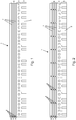
- Fig. 1 shows a schematic representation of a first embodiment of the scale according to the invention.
- the scale 1 comprises an absolute track 3 applied to an insulator substrate 2, a relative or incremental track 4 and a coding 5, which is also referred to as a coding track.
- the absolute track 3 and the relative track 4 are applied as conductive sections or conductor tracks on the insulator substrate 2 on the front side of the scale. But you can also on the back be upset.
- the absolute and relative tracks 3, 4 can also be designed as optical tracks with light and dark sections.
- the correspondingly marked sections can also have a different magnetic structure, ie magnetic and non-magnetic sections alternate. The two tracks 3 and 4 can thus be detected with a suitable sensor.
- the coding 5, which has three coding elements 6, is arranged above the absolute track 3 and the relative track 4.
- a coding element 6 has two electrodes 7 and a conductive connection 8 between the two electrodes 7.
- a first electrode 7 designed as a conductor track the second not in FIG Fig. 1
- the visible electrode is arranged, for example, as a reference electrode on the back of the printed circuit board (PCB).
- the second electrode can also be provided on the front side of the printed circuit board (PCB).
- the coding element 6 extends over the entire length of the scale 1.
- One electrode 7 is as in FIG Fig. 1 shown arranged on the front side of the circuit board substrate 2. Another arrangement, for example on different sides of the circuit board, is also possible.
- the conductive connection 8 of each coding element 6 in this embodiment is designed as a fuse between the electrodes 7, with all three conductive connections in the longitudinal direction at the same level (in Fig. 1 left) are trained.
- a possible configuration of the conductive connection 8 is exemplified below with reference to FIG Figures 5 and 6 explained.
- the arrangement of exactly three coding elements 6, each with a conductive connection 8, which can be irreversibly destroyed, results in a maximum number of 2 3 , that is to say eight different coding options. As a result, eight scales can be arranged next to one another, each with a different coding when it is ready for operation.
- Fig. 2 a second embodiment of the scale 1 according to the invention is shown.
- the absolute and relative tracks 3, 4 arranged on the insulator substrate 2 are identical to the first one, in FIG Fig. 1 illustrated embodiment.
- Coding 5 is also analogous to Fig. 1 formed by means of three coding elements 6.
- each coding element 6 in Fig. 2 not just one, but a plurality of, here nine, conductive connections 8, each of which is arranged between two electrodes, one of which is visible on the front side. All of the conductive connections 8 of a coding element 6 are accordingly connected to the electrodes 7 in an identical manner.
- a preferably executed scale 1 has, for. B. a length of 50 cm, the distances between the conductive connections 8 being about 22 mm, which has proven to be particularly advantageous for the measurement. Larger or smaller distances are also possible.
- a scale 1 according to the embodiment Fig. 2 takes place analogously to the embodiment according to Fig. 1 : an electrical current is applied to the electrodes 7 of each coding element 6 simultaneously or one after the other, whereby all conductive connections 8 of a coding element 6 are irreversibly destroyed.
- an electrical current is applied to the electrodes 7 of each coding element 6 simultaneously or one after the other, whereby all conductive connections 8 of a coding element 6 are irreversibly destroyed.
- FIG. 11 shows a schematic representation of a length measuring system 10 according to the first embodiment of the present invention, with three scales 1, which are identical to that in FIG Fig. 1 scale shown are arranged side by side.
- the transition between the scales must be as seamless and exact as possible, so that measurement inaccuracies are avoided as far as possible. It is also important that the rules are aligned as precisely as possible in the longitudinal direction. Due to the manufacturing techniques that are possible today, especially for printed circuit boards (PCBs), this is usually guaranteed without great effort.
- PCBs printed circuit boards
- a first sensor unit 11 and a second sensor unit 12 are arranged in the vicinity of the length measuring system 10 in such a way that they can detect the absolute and relative track 3, 4 or the coding 5.
- the sensor units 11, 12 are arranged next to the length measuring system 10 for reasons of clarity. It goes without saying that in the case of a perpendicular detection angle, that is to say perpendicular to the plane of the drawing and to the plane of the scales, the sensor units are arranged above the scales in order to enable optimal detection.
- Sensors in the two sensor units 11, 12 work, for example, according to the optical principle, in which the sequence of dark and light areas is detected by means of appropriate optical transmitters and receivers. There are other designs for the sensors are also possible, ie a magnetic, inductive, electromagnetic or capacitive measurement or a combination thereof.
- the sensor or the sensors of the first and second sensor units 11, 12 detect the coding 5, for example according to a capacitive measuring method by means of a capacitive distance sensor, in which the sensor and a conductive counter surface form an electrical capacitor, the conductive counter surface, ie the Conductor tracks on the scale, and the distance determines the capacitance.
- a capacitive distance sensor in which the sensor and a conductive counter surface form an electrical capacitor, the conductive counter surface, ie the Conductor tracks on the scale, and the distance determines the capacitance.
- the coding 5 for example by means of an inductive sensor.
- a control unit 13 detects the measurement signals from the first and second sensor units 11, 12 and evaluates them. In order to be able to precisely record the transitions between the scales, the control unit 13 uses the signals from the sensor units 11 and 12 to identify whether a transition is present. Accordingly, a switch is made to the sensor unit not positioned at the transition, and the signals are received and evaluated from there in order to be able to output the recorded length information on the length scale directly or indirectly.
- Fig. 4 is a too Fig. 3 analog representation, where in Fig. 4 schematically three scales 1 according to Fig. 2 are arranged side by side.
- the arrangement of the sensor units 11, 12 and the control unit 13 and the function of the elements are identical to those with reference to Fig. 3 described embodiment.
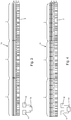
- Fig. 5 shows a schematic representation of the front of a third embodiment of the scale according to the invention.
- the scale 1 according to the invention has an absolute track 3, a relative track 4 and a coding or coding track 5 on a printed circuit board (PCB) 2.
- the coding 5 comprises five coding elements 6, each of which is divided into a plurality of coding segments in the longitudinal direction.
- the individual coding segments of each coding element 6 represent on the in Fig. 5
- the front side shown represents an electrode that is not conductively connected to the longitudinally adjacent electrodes of the next coding segment.
- the scale 1 has a reference electrode 9 on the front side, which represents the second electrode for each electrode pair.
- the conductive connections 8 of each coding element 6 are shown in FIG Fig. 5 not shown since they are not visible in this view in the embodiment shown, as is explained below.
- Fig. 6 shows a schematic representation of a section of the back of the third embodiment of the scale according to the invention with two coding segments.
- the images indicate FIGS. 5 and 6 different orders of magnitude and are therefore to be regarded as purely schematic.
- the scale 1 on the back of the printed circuit board 2 has a large area of conductive area 14, which is through-contacted with the reference electrode 9 on the front, ie is conductively connected, and is therefore at the potential of the reference electrode 9.
- the conductive area 14 is provided at the level of each of the five coding elements 6 present on the front side with a number of non-conductive surfaces 15 corresponding to the number of coding elements 6.
- Each non-conductive surface 15 is assigned to a coding element 6 and surrounds an electrode 16 which has a conductive connection 8 on one side, which is designed to be irreversibly destructible for the purpose of coding.
- the conductive connection 8 is a connection between the electrode 16 on the rear side and the associated electrode of the coding element 6 on the front side of the scale 1.
- Such vias vertical interconnect access; VIA
- VIA vertical interconnect access
- Breaking or destroying the conductive connection (s) 8 can occur in the Figures 5 and 6 shown embodiment from both sides of the scale 1, since both electrodes 6, 9 on the front and the conductive area 14 and the electrodes 16 on the back are present and accessible. It is also possible on different Contacting sites to bring about the destruction and thus the coding.
- a particularly suitable contacting or coding device is used, which, for example, can have several contact elements for simultaneous contacting of a plurality of electrodes.
- the contacting or coding device is programmed accordingly and automatically encodes each scale. It is possible that the coding is carried out before or after the final arrangement of the scales in a measuring system.
- Breaking or destroying the conductive connection 8 in each coding element 6 or in each coding segment makes use of the properties and functionality of a PCB fuse in the preferred embodiments. It must be ensured that the potential differences and currents are sufficiently dimensioned when the contacting or coding device is applied, so that a reliable and permanent destruction of the conductive connection 8 is guaranteed.
- the present invention is applicable not only to length measuring systems in a straight alignment, but also to angle measuring systems with corresponding circle segment scales.
- a measuring system which can be produced inexpensively, in mass production, with sophisticated technologies and without complex production techniques. It guarantees reliable measurement and can be used flexibly and variably.
Landscapes
- Physics & Mathematics (AREA)
- General Physics & Mathematics (AREA)
- Engineering & Computer Science (AREA)
- Power Engineering (AREA)
- Microelectronics & Electronic Packaging (AREA)
- Transmission And Conversion Of Sensor Element Output (AREA)
Description
- Die vorliegende Erfindung liegt auf dem Gebiet der Messtechnik und Automatisierungstechnik und betrifft ein Messsystem zur Absolutwerterfassung von Winkeln oder Wegen, auch Messgeber, Längengeber oder Winkelencoder genannt.
- Bekannte Längen- oder Winkelmesssysteme weisen eine Mehrzahl von gleichartigen Maßstäben und eine Sensoreinheit auf, die entlang der Maßstäbe bewegt wird und die darauf gespeicherten Informationen erfasst. Jeder Maßstab umfasst dabei mindestens eine Absolut- oder Relativspur, auch Inkrementalspur genannt, sowie eine Elementcodierung. Die Elementcodierung dient der Kennzeichnung bzw. Identifizierung der ansonsten identischen Maßstäbe und somit der Positionsbestimmung für die Sensoreinheit.
- Ein bekanntes Messsystem ist beispielsweise aus der
DE 101 17 193 A1 bekannt. Dort ist ein Messsystem mit mehreren nebeneinander angeordneten Maßstäben offenbart, die eine Absolutspur, eine Inkrementalspur und eine Codierspur aufweisen. Die Absolut- und Inkrementalspuren der einzelnen Maßstäbe sind identisch, nur die Codierspur unterscheidet sich jeweils von Maßstab zu Maßstab. - Nachteilig an dem Messsystem aus der
DE 101 17 193 A1 ist, dass jeder einzelne Maßstab zwar identische Merkmale wie Absolut- und Inkrementalspur aufweist, die Codierspur jedoch individuell auf jeden einzelnen Maßstab aufgebracht werden muss. Dies ist insbesondere bei optischen Systemen sehr aufwendig. - Ein Messsystem nach dem kapazitiven Messprinzip mit als Elektroden auf einer Leiterplatte aufgebrachten Absolut- und Inkrementalspuren ist in der
EP 0 836 076 A1 offenbart. -
EP2 357 451 A1 ,JP 2006 170790 A EP 1 770 374 A2 undJP 2012 149891 A - Eine Gerätecodierung durch Leiterplattensicherungen und ein Verfahren zur Kennzeichnung von Leiterplatten sind in der
DE 10 2007 036 836 A1 bzw. derEP 0 986 289 A2 offenbart. - Es ist daher die Aufgabe der vorliegenden Erfindung, ein Messsystem bereitzustellen, das zumindest einige der oben genannten Nachteile überwindet und kostengünstig, in Massenfertigung, mit ausgereiften Technologien und ohne komplexe Fertigungstechniken hergestellt werden kann.
- Diese Aufgabe wird durch den Gegenstand mit den Merkmalen des Anspruchs 1 erfüllt. Vorteilhafte Ausführungsformen sind in den abhängigen Ansprüchen beschrieben.
- Erfindungsgemäß ist ein Maßstab für ein Längenmesssystem zur Absolutwerterfassung von Winkeln oder Wegen, der auf einer Leiterplatte (PCB) mindestens eine Spur zur Kennzeichnung von Längen- bzw. Winkelinformationen sowie eine Codierung zur Kennzeichnung des Maßstabs aufweist, wobei die Codierung mindestens ein Codierelement aufweist, das mindestens zwei Elektroden und eine elektrisch leitende Verbindung zwischen den Elektroden auf einem Isolatorsubstrat umfasst, wobei die leitende Verbindung dazu eingerichtet ist, zur Kennzeichnung des Maßstabs durch wahlweises Anlegen eines elektrischen Stroms an mindestens ein Codierelement irreversibel zerstört zu werden. Der entscheidende Vorteil des erfindungsgemäßen Maßstabs liegt darin, dass mehrere Maßstäbe identischen Typs auf dieselbe Art und Weise hergestellt werden können, und diese nach der Herstellung und vor der Montage oder nach dem Einbau in ein entsprechendes Messsystem codiert werden können. Die irreversible Zerstörung der leitenden Verbindung zwischen den entsprechenden Elektroden auf dem Isolatorsubstrat erfolgt ähnlich wie bei einer Schmelzsicherung, wobei die entsprechende thermische Leitfähigkeit des Substratmaterials und das Leitermaterial berücksichtigt werden müssen, damit die entsprechende Leistung zur Verfügung gestellt wird, um die elektrische Verbindung bis zum Durchschmelzen aufzuheizen. Derartige Maßstäbe eignen sich hervorragend für die massenhafte Herstellung, da die Strukturen für die Codierung auf der Leiterplatte für die Verarbeitung großer Stückzahlen hervorragend geeignet sind. Das Anlegen eines entsprechenden Stroms an die Elektroden erfolgt dediziert für jedes Codierelement durch Anschließen der entsprechenden Elektroden an eine Stromquelle, deren Leistung auf die Materialien wie oben beschrieben abgestimmt ist.
- Mit besonderem Vorteil ist das mindestens eine Codierelement in eine Mehrzahl von Codiersegmenten segmentiert, wobei jedes Codiersegment zwei Elektroden mit einer leitenden Verbindung dazwischen aufweist. Dadurch ergibt sich eine genauere Messung, weil parasitäre Kapazitäten wegfallen. Jedes Codierelement weist dann zwar mehr leitende Verbindungen auf, die entsprechend irreversibel zu zerstören sind, die Längen- bzw. Winkelmessung am Maßstab kann jedoch weniger fehleranfällig erfolgen. Die Anordnung der Codiersegmente mit der leitenden Verbindung kann z.B. gleichmäßig über die Ausdehnung des Codierelements bzw. des Maßstabs sein. Bevorzugt sind jeweils die aneinander grenzenden oder auf einer gemeinsamen Seite der Leiterplatte vorhandenen Elektroden jedes Codiersegments als Referenzelektrode bzw. Groundelektrode ausgebildet.
- Dabei ist zumindest eine Elektrode jedes Codiersegments potentialmäßig von der entsprechenden angrenzenden Elektrode getrennt. Das Anlegen des elektrischen Stroms zur irreversiblen Zerstörung erfolgt deshalb bei mehreren Codiersegmenten mehrfach, d.h. einmal pro Codiersegment. Dadurch, dass für die Codierung, also den Vorgang der irreversiblen Zerstörung, eine Hilfsvorrichtung mit einer der Anzahl der zu zerstörenden leitenden Verbindungen entsprechenden Anzahl von Kontaktelementen verwendet wird, ergibt sich kein wesentlicher Mehraufwand.
- Bevorzugt weist der Maßstab eine Absolutspur und eine Inkrementalspur auf, wobei vorzugsweise die Absolutspur und/oder die Inkrementalspur als Leiterbahn, magnetische Bahn oder aufgedruckte Bahn ausgebildet sind. Wenn Absolut- und Inkrementalspur als Leiterbahn ausgebildet sind, dann ergibt sich der Vorteil, dass die Spuren einschließlich der Codierung bzw. der Codierspur auf dem Maßstab mit derselben Herstellungstechnik gefertigt werden können, was zu Einsparungen beim Fertigungsprozess führt.
- Mit weiterem Vorteil ist die Leiterplatte fotochemisch, mittels Stanz- oder Drahtlegetechnik, mittels Siebdruck oder mittel Frästechnik herstellbar. Die genannten Technologien sind ausgereifte geeignete Verfahren zur Herstellung von Leiterplatten und bieten sich für die Massenherstellung des erfindungsgemäßen Maßstabs an. Bevorzugt ist das in der Halbleitertechnik meist eingesetzte fotochemische Herstellungsverfahren.
- Damit die Zerstörung der leitenden Verbindung durch das Anlegen des Stroms auch tatsächlich irreversibel ist, weist die leitende Verbindung vorzugsweise eine Sollbruchstelle auf. Damit ist im besonderen Maße gewährleistet, dass die Codierung des Maßstabs präzise erfolgen kann.
- Besonders bevorzugt ist es, dass sowohl eine intakte als auch eine irreversibel zerstörte leitende Verbindung von einer Person visuell überprüfbar ist. Damit lässt sich nicht nur anhand eines Sensors überprüfen, ob die richtige Codierung für jeden einzelnen Maßstab korrekt durchgeführt worden ist, sondern auch von einem menschlichen Auge, mit oder ohne optische Hilfsmittel wie einer Lupe oder dergleichen. Dies bietet Vorteile beim Einbau der entsprechenden Maßstäbe.
- Weiterhin erfindungsgemäß ist ein Längenmesssystem zur Absolutwerterfassung von Winkeln oder Wegen mit einer Mehrzahl von nebeneinander angeordneten Maßstäben, die wie oben definiert aufgebaut sind, einer ersten Sensoreinheit mit mindestens einem Sensor zur Erfassung der Längen- bzw. Winkelinformationen und der Codierung jedes der Mehrzahl von Maßstäben, wobei die Längen- bzw. Winkelinformationen auf der mindestens einen Spur jedes Maßstabs identisch sind, und wobei die Codierung jedes Maßstabs des Längenmesssystems derart ausgebildet ist, dass sie sich in mindestens einem Codierelement von einem anderen Maßstab unterscheidet. Die Bildung eines solchen Längenmesssystems mit einer Mehrzahl von besonders codierten Maßstäben kann damit einfach erfolgen, weil das Codierungsverfahren für jeden einzelnen Maßstab dieselbe Infrastruktur nutzen kann und ebenfalls einfach aufgebaut ist. Die Codierung der einzelnen Maßstäbe kann flexibel entweder vor dem Anordnen der einzelnen Maßstäbe zu einem Gesamtmesssystem erfolgen oder auch danach, wenn die einzelnen Maßstäbe schon nebeneinander angeordnet sind.
- Vorteilhafterweise umfasst das Längenmesssystem eine zweite Sensoreinheit mit mindestens einem Sensor zur Erfassung der Längen- bzw. Winkelinformationen und der Codierung und eine Steuereinheit. Damit können beim Übergang von nebeneinander angeordneten Maßstäben sämtliche Spuren sicher erfasst werden. Die Steuereinheit schaltet dabei zwischen der ersten und der zweiten Sensoreinheit je nach Vollständigkeit des erfassten Signals hin und her. Die erste und zweite Sensoreinheit sind dabei vorzugsweise identisch ausgebildet, um zusätzlichen Aufwand zu sparen. Mit anderen Worten wird dabei durch die identische zweite Sensoreinheit eine Redundanz geschaffen, die speziell für die Erfassung der Übergänge der Maßstäbe wichtig ist.
- Das Messprinzip der Sensoren in der ersten bzw. zweiten Sensoreinheit beruht vorzugsweise auf einem optischen, magnetischen, induktiven, elektromagnetischen oder kapazitiven Messverfahren oder aus einer Kombination davon. Derartige Sensoren sind im Prinzip bekannt, sie basieren auf physikalischen Messverfahren bzw. Parametern, z. B. einer variablen Induktivität oder einer variablen Kapazität.
- Weiterhin erfindungsgemäß ist ein Verfahren zur Herstellung eines Längenmesssystems zur Absolutwerterfassung von Winkeln oder Wegen, das folgende Schritte umfasst: a) Bereitstellen einer Mehrzahl von zunächst identischen Maßstäben wie oben beschrieben, wobei die Längen- bzw. Winkelinformationen auf der mindestens einen Spur jedes Maßstabs und die Codierelemente jedes Maßstabs des Längenmesssystems zunächst identisch sind, b) Anordnen der Mehrzahl von Maßstäben nebeneinander, c) Kennzeichnen jedes der Mehrzahl von Maßstäben durch wahlweises Anlegen eines Stroms an mindestens ein Codierelement, wobei die leitenden Verbindungen irreversibel zerstört werden, so dass jeder der Mehrzahl von Maßstäben nunmehr eine unterschiedliche Codierung aufweist, wobei die Schritte b) und c) auch in umgekehrter Reihenfolge durchführbar sind.
- Die vorliegende Erfindung wird nachfolgend anhand von bevorzugten Ausführungsformen unter Bezugnahme auf die Zeichnungen beschrieben, in denen:
- Fig. 1
- eine schematische Darstellung einer ersten Ausführungsform des erfindungsgemäßen Maßstabs zeigt,
- Fig. 2
- eine schematische Darstellung einer zweiten Ausführungsform des erfindungsgemäßen Maßstabs zeigt,
- Fig. 3
- eine schematische Darstellung eines Längenmesssystems gemäß der ersten Ausführungsform zeigt,
- Fig. 4
- eine schematische Darstellung eines Längenmesssystems gemäß der zweiten Ausführungsform des erfindungsgemäßen Maßstabs zeigt,
- Fig. 5
- eine schematische Darstellung der Vorderseite einer dritten Ausführungsform des erfindungsgemäßen Maßstabs zeigt, und
- Fig. 6
- eine schematische Darstellung eines Ausschnitts der Rückseite der dritten Ausführungsform des erfindungsgemäßen Maßstabs zeigt.
-
Fig. 1 zeigt eine schematische Darstellung einer ersten Ausführungsform des erfindungsgemäßen Maßstabs. Der Maßstab 1 umfasst eine auf einem Isolatorsubstrat 2 aufgebrachte Absolutspur 3, eine Relativ- oder Inkrementalspur 4 und eine Codierung 5, die auch als Codierspur bezeichnet wird. Die Absolutspur 3 und die Relativspur 4 sind in der dargestellten Ausführungsform als leitende Abschnitte bzw. Leiterbahnen auf dem Isolatorsubstrat 2 auf der Vorderseite des Maßstabs aufgebracht. Sie können aber auch auf der Rückseite aufgebracht sein. Alternativ können Absolut- und Relativspur 3, 4 auch als optische Spuren mit hellen und dunklen Abschnitten ausgebildet sein. In ähnlicher Weise können die entsprechend markierten Abschnitte auch eine unterschiedliche magnetische Struktur aufweisen, d.h. es wechseln sich magnetische und nichtmagnetische Abschnitte ab. Die beiden Spuren 3 und 4 sind damit mit einem geeigneten Sensor erfassbar. - Oberhalb der Absolutspur 3 und der Relativspur 4 ist die drei Codierelemente 6 aufweisende Codierung 5 angeordnet. Ein Codierelement 6 weist zwei Elektroden 7 und eine leitende Verbindung 8 zwischen den beiden Elektroden 7 auf. In
Fig. 1 erkennt man eine als Leiterbahn ausgebildete erste Elektrode 7, die zweite, nicht inFig. 1 sichtbare Elektrode ist beispielsweise als Referenzelektrode auf der Rückseite der Leiterplatte (PCB) angeordnet. Die zweite Elektrode kann auch auf der Vorderseite der Leiterplatte (PCB) vorgesehen sein. Das Codierelement 6 erstreckt sich in der dargestellten Ausführungsform über die gesamte Länge des Maßstabs 1. Die eine Elektrode 7 ist wie inFig. 1 dargestellt auf der Vorderseite des Leiterplattensubstrats 2 angeordnet. Es ist auch eine andere Anordnung, beispielsweise auf unterschiedlichen Seiten der Leiterplatte möglich. - Die leitende Verbindung 8 jedes Codierelements 6 ist in dieser Ausführungsform als Schmelzsicherung zwischen den Elektroden 7 ausgebildet, wobei alle drei leitenden Verbindungen in Längsrichtung auf einer Höhe (in
Fig. 1 links) ausgebildet sind. Eine mögliche Ausgestaltung der leitenden Verbindung 8 wird weiter unten beispielhaft unter Bezugnahme auf dieFig. 5 und 6 erläutert. Durch die Anordnung von genau drei Codierelementen 6 mit jeweils einer leitenden Verbindung 8, die irreversibel zerstörbar ist, ergibt sich eine maximale Anzahl von 23, also acht unterschiedlichen Codierungsmöglichkeiten. Es können folglich acht Maßstäbe nebeneinander angeordnet werden, wobei jeder im funktionsbereiten Zustand eine unterschiedliche Codierung aufweist. - In
Fig. 2 ist eine zweite Ausführungsform des erfindungsgemäßen Maßstabs 1 dargestellt. Die auf dem Isolatorsubstrat 2 angeordneten Absolut- und Relativspuren 3, 4 sind identisch zur ersten, inFig. 1 dargestellten Ausführungsform. Die Codierung 5 ist ebenfalls analog zuFig. 1 mittels dreier Codierelemente 6 ausgebildet. Allerdings weist jedes Codierelement 6 inFig. 2 nicht nur eine, sondern eine Mehrzahl von, hier neun, leitenden Verbindungen 8 auf, die jeweils zwischen zwei Elektroden angeordnet sind, von denen eine auf der Vorderseite sichtbar ist. Sämtliche leitenden Verbindungen 8 eines Codierelements 6 sind demnach auf identische Weise mit den Elektroden 7 verbunden. Da die neun leitenden Verbindungen 8 hier in im Wesentlichen gleichen Abständen über die Länge des Codierelements 6 und damit den Maßstab 1 verteilt sind, sind die Eigenkapazitäten der Elektroden 7, also der Leitungsbahnen kleiner und haben beispielsweise bei der kapazitiven Erfassung der Codierung einen geringeren negativen Einfluss. Ein bevorzugt ausgeführter Maßstab 1 weist z. B. eine Länge von 50 cm auf, wobei die Abstände der leitenden Verbindungen 8 etwa 22 mm betragen, was sich als besonders vorteilhaft für die Messung erwiesen hat. Es sind auch größere oder kleinere Abstände möglich. - Die Individualisierung eines Maßstabs 1 nach der Ausführungsform aus
Fig. 2 erfolgt analog zur Ausführungsform nachFig. 1 : an die Elektroden 7 jedes Codierelements 6 wird gleichzeitig oder auch nacheinander ein elektrischer Strom angelegt, wodurch jeweils alle leitenden Verbindungen 8 eines Codierelements 6 irreversibel zerstört werden. Für die wirksame Codierung jedes Codierelements 6 muss z. B. mindestens jede Elektrode des entsprechenden Codiersegments und die Ground- bzw. Referenzelektrode kontaktiert werden. -
Fig. 3 zeigt eine schematische Darstellung eines Längenmesssystems 10 gemäß der ersten Ausführungsform der vorliegenden Erfindung, wobei beispielhaft drei Maßstäbe 1, die identisch mit dem inFig. 1 dargestellten Maßstab sind, nebeneinander angeordnet sind. Der Übergang zwischen den Maßstäben muss möglichst nahtlos und exakt sein, so dass Messungenauigkeiten so weit wie möglich vermieden werden. Auch eine möglichst exakte Ausrichtung der Maßstäbe in Längsrichtung ist wichtig. Durch die heute möglichen Fertigungstechniken, insbesondere für Leiterplatten (PCBs), ist dies in aller Regel ohne großen Aufwand gewährleistet. - Eine erste Sensoreinheit 11 und eine zweite Sensoreinheit 12 sind derart in der Nähe des Längenmesssystems 10 angeordnet, dass sie die Absolut- und Relativspur 3, 4 bzw. die Codierung 5 erfassen können. In der Darstellung der
Fig. 3 sind die Sensoreinheiten 11, 12 aus Anschaulichkeitsgründen neben dem Längenmesssystem 10 angeordnet. Es versteht sich, dass bei einem senkrechten Erfassungswinkel, d.h. senkrecht zur Zeichenebene und zur Ebene der Maßstäbe, die Sensoreinheiten über den Maßstäben angeordnet sind, um eine optimale Erfassung zu ermöglichen. Sensoren in den beiden Sensoreinheiten 11, 12 arbeiten beispielsweise nach dem optischen Prinzip, bei dem die Abfolge von dunklen und hellen Stellen mittels entsprechender optischer Sender und Empfänger erfasst wird. Es sind auch andere Ausführungen für die Sensoren möglich, d.h. eine magnetische, induktive, elektromagnetische oder kapazitive Messung oder eine Kombination daraus. - In der in den
Fig. 3 und 4 dargestellten Ausführungsform erfassen der Sensor bzw. die Sensoren der ersten und zweiten Sensoreinheit 11, 12 die Codierung 5 beispielsweise nach einem kapazitiven Messverfahren mittels eines kapazitiven Abstandssensors, bei dem der Sensor und eine leitende Gegenfläche einen elektrischen Kondensator bilden, wobei die leitende Gegenfläche, d.h. die Leiterbahnen auf dem Maßstab, und der Abstand die Kapazität bestimmt. Es ist aber auch möglich, die Codierung 5 mit anderen Sensoren zu erfassen, beispielsweise mittels eines induktiven Sensors. - Eine Steuereinheit 13 erfasst die Messsignale der ersten und zweiten Sensoreinheiten 11, 12 und wertet diese aus. Um die Übergänge zwischen den Maßstäben exakt erfassen zu können, erkennt die Steuereinheit 13 anhand der Signale der Sensoreinheiten 11 bzw. 12, ob ein Übergang vorhanden ist. Dementsprechend wird dann auf die jeweils nicht am Übergang positionierte Sensoreinheit geschaltet und die Signale werden von dort empfangen und ausgewertet, um die erfasste Längeninformation auf dem Längenmassstab direkt oder indirekt ausgeben zu können.
-
Fig. 4 ist eine zuFig. 3 analoge Darstellung, wobei inFig. 4 schematisch drei Maßstäbe 1 gemäßFig. 2 nebeneinander angeordnet sind. Die Anordnung der Sensoreinheiten 11, 12 sowie der Steuereinheit 13 und die Funktion der Elemente sind identisch zur mit Bezug aufFig. 3 beschriebenen Ausführungsform. -
Fig. 5 zeigt eine schematische Darstellung der Vorderseite einer dritten Ausführungsform des erfindungsgemäßen Maßstabs. Wie in den oben beschriebenen ersten und zweiten Ausführungsformen weist der erfindungsgemäße Maßstab 1 auf einer Leiterplatte (PCB) 2 eine Absolutspur 3, eine Relativspur 4 und eine Codierung bzw. Codierspur 5 auf. In dieser dritten Ausführungsform umfasst die Codierung 5 fünf Codierelemente 6, die in Längsrichtung jeweils in eine Mehrzahl von Codiersegmenten aufgeteilt sind. Die einzelnen Codiersegmente jedes Codierelements 6 stellen auf der inFig. 5 dargestellten Vorderseite eine Elektrode dar, die jeweils nicht mit den in Längsrichtung angrenzenden Elektroden des nächsten Codiersegments leitend verbunden. Jeweils an den Rändern weist der Maßstab 1 auf der Vorderseite eine Referenzelektrode 9 auf, die die zweite Elektrode für jedes Elektrodenpaar darstellt. Die leitenden Verbindungen 8 jedes Codierelements 6 sind inFig. 5 nicht abgebildet, da sie in der dargestellten Ausführungsform nicht in dieser Ansicht sichtbar sind, wie im Folgenden erläutert ist. -
Fig. 6 zeigt eine schematische Darstellung eines Ausschnitts der Rückseite der dritten Ausführungsform des erfindungsgemäßen Maßstabs mit zwei Codiersegmenten. Aus Darstellungsgründen weisen die Abbildungen ausFig. 5 und Fig. 6 unterschiedliche Größenordnungen auf und sind deshalb als rein schematisch anzusehen. InFig. 6 weist der Maßstab 1 auf der Rückseite der Leiterplatte 2 großflächig einen leitenden Bereich 14 auf, der mit der Referenzelektrode 9 auf der Vorderseite durchkontaktiert, d.h. leitend verbunden, ist und deshalb auf dem Potential der Referenzelektrode 9 liegt. - Der leitende Bereich 14 ist auf Höhe jeder der fünf auf der Vorderseite vorhandenen Codierelemente 6 mit einer der Anzahl von Codierelementen 6 entsprechenden Anzahl von nichtleitenden Flächen 15 versehen. Jede nichtleitende Fläche 15 ist einem Codierelement 6 zugeordnet und umgibt eine Elektrode 16, die auf einer Seite eine leitende Verbindung 8 aufweist, die zum Zwecke der Codierung als irreversibel zerstörbar ausgebildet ist. Die leitende Verbindung 8 ist in dieser Ausführungsform eine Verbindung zwischen der Elektrode 16 auf der Rückseite und der zugehörigen Elektrode des Codierelements 6 auf der Vorderseite des Maßstabs 1. Derartige Durchkontaktierungen (engl. vertical interconnect access; VIA) sind bei integrierten Schaltungen seit langem üblich und dienen hauptsächlich dazu, bei Platzmangel auf einer Seite sowohl Vorder- als auch Rückseite einer Leiterplatte (PCB) mit Bauelementen zu bestücken. Da in den
Fig. 5 und 6 Draufsichten auf die Vorder- bzw. Rückseite eines Maßstabs 1 dargestellt sind, sind die Durchkontaktierungen nicht abgebildet. Auch bei der Ausführungsform der vorliegenden Erfindung wurde aus Platzgründen eine Elektrode 16 eines Codierelements 6 auf der Rückseite des Maßstabs 1 angeordnet. Weil die auf der Rückseite des Maßstabs 1 vorhandenen Elemente, d.h. die nichtleitenden Flächen 15, die Elektroden 16 und die leitende Verbindung 8, nicht alle direkt untereinander angeordnet werden können, sind sie seitlich versetzt positioniert. Bei einer entsprechenden Größe des Maßstabs können sie jedoch auch untereinander angeordnet sein, wie in den ersten und zweiten Ausführungsformen dargestellt. - Das Aufbrechen bzw. Zerstören der leitenden Verbindung(en) 8 kann bei der in den
Fig. 5 und 6 gezeigten Ausführungsform von beiden Seiten des Maßstabs 1 her erfolgen, da beide Elektroden 6, 9 auf der Vorderseite sowie der leitende Bereich 14 und die Elektroden 16 auf der Rückseite vorhanden und zugänglich sind. Es ist auch möglich, auf unterschiedlichen Seiten zu kontaktieren, um die Zerstörung und damit die Codierung herbeizuführen. Dazu wird eine besonders geeignete Kontaktier- oder Codiervorrichtung eingesetzt, die z.B. mehrere Kontaktelemente zur gleichzeitigen Kontaktierung einer Mehrzahl von Elektroden aufweisen kann. Die Kontaktier- oder Codiereinrichtung wird entsprechend programmiert und führt automatisch die Codierung jedes Maßstabs durch. Dabei ist es möglich, dass vor oder nach der finalen Anordnung der Maßstäbe in einem Messsystem die Codierung durchgeführt wird. - Das Durchbrechen bzw. Zerstören der leitenden Verbindung 8 bei jedem Codierelement 6 bzw. in jedem Codiersegment bedient sich in den bevorzugten Ausführungsformen der Eigenschaften und der Funktionalität einer PCB Schmelzsicherung. Dabei ist sicherzustellen, dass die Potentialunterschiede und Ströme bei Anlegen der Kontaktier- oder Codiereinrichtung ausreichend dimensioniert sind, damit eine zuverlässige und dauerhafte Zerstörung der leitenden Verbindung 8 gewährleistet ist.
- Die vorliegende Erfindung ist nicht nur auf Längenmesssysteme in einer geraden Ausrichtung, sondern auch auf Winkelmesssysteme mit entsprechenden Kreissegment-Maßstäben anwendbar.
- Mit dem erfindungsgemäßen Gegenstand wird ein Messsystem bereitgestellt, das kostengünstig, in Massenfertigung, mit ausgereiften Technologien und ohne komplexe Fertigungstechniken hergestellt werden kann. Es gewährleistet eine zuverlässige Messung und ist flexibel und variabel einsetzbar.
Claims (12)
- Maßstab (1) für ein Längenmesssystem zur Absolutwerterfassung von Winkeln oder Wegen, der eine Leiterplatte (2) und auf der Leiterplatte (2) mindestens eine Spur (3, 4) zur Kennzeichnung von Längen- bzw. Winkelinformationen sowie eine Codierung (5) zur Kennzeichnung des Maßstabs (1) aufweist,
dadurch gekennzeichnet, dass
die Codierung (5) mindestens ein Codierelement (6) aufweist, das mindestens zwei Elektroden (7, 9, 14) und eine elektrisch leitende Verbindung (8) zwischen den Elektroden (7, 9, 14) auf einem Isolatorsubstrat umfasst, wobei die leitende Verbindung (8) dazu eingerichtet ist, zur Kennzeichnung des Maßstabs (1) durch wahlweises Anlegen eines elektrischen Stroms an mindestens ein Codierelement (6) irreversibel zerstört zu werden. - Maßstab (1) nach Anspruch 1, dadurch gekennzeichnet, dass das mindestens eine Codierelement (6) in eine Mehrzahl von Codiersegmenten segmentiert ist, wobei jedes Codiersegment zwei Elektroden (7, 9, 14) mit einer leitenden Verbindung (8) dazwischen aufweist.
- Maßstab (1) nach Anspruch 2, dadurch gekennzeichnet, dass die Elektroden (7, 9, 14) jedes Codiersegments potentialmäßig getrennt sind.
- Maßstab (1) nach einem der vorhergehenden Ansprüche, dadurch gekennzeichnet, dass er eine Absolutspur (3) und eine Inkrementalspur (4) aufweist.
- Maßstab (1) nach Anspruch 4, dadurch gekennzeichnet, dass die Absolutspur (3) und/oder die Inkrementalspur (4) als Leiterbahn, magnetische Bahn oder aufgedruckte Bahn ausgebildet sind.
- Maßstab (1) nach einem der vorhergehenden Ansprüche, dadurch gekennzeichnet, dass die Leiterplatte (2) fotochemisch, mittels Stanz- oder Drahtlegetechnik, mittels Siebdruck oder mittels Frästechnik herstellbar ist.
- Maßstab (1) nach einem der vorhergehenden Ansprüche, dadurch gekennzeichnet, dass die leitende Verbindung (8) eine Sollbruchstelle aufweist.
- Maßstab (1) nach einem der vorhergehenden Ansprüche, dadurch gekennzeichnet, dass sowohl eine intakte als auch eine irreversibel zerstörte leitende Verbindung (8) von einer Person visuell überprüfbar ist.
- Längenmesssystem (10) zur Absolutwerterfassung von Winkeln oder Wegen mit
einer Mehrzahl von nebeneinander angeordneten Maßstäben (1) nach einem der vorhergehenden Ansprüche,
einer ersten Sensoreinheit (11) mit mindestens einem Sensor zur Erfassung der Längen- bzw. Winkelinformationen und der Codierung (5) jedes der Mehrzahl von Maßstäben (1),
wobei die Längen- bzw. Winkelinformationen auf der mindestens einen Spur (3, 4) jedes Maßstabs (1) identisch sind, und
wobei die Codierung (5) jedes Maßstabs (1) des Längenmesssystems (10) derart ausgebildet ist, dass sie sich in mindestens einem Codierelement (6) von einem anderen Maßstab (1) unterscheidet. - Längenmesssystem (10) nach Anspruch 9, dadurch gekennzeichnet, dass es eine zweite Sensoreinheit (12) mit mindestens einem Sensor zur Erfassung der Längen- bzw. Winkelinformationen und der Codierung (5) jedes der Mehrzahl von Maßstäben (1) und eine Steuereinheit (13) aufweist.
- Längenmesssystem (10) nach einem der Ansprüche 9 bis 10, dadurch gekennzeichnet, dass das Messprinzip der Sensoren der ersten und/oder zweiten Sensoreinheit (11, 12) auf einem optischen, magnetischen, induktiven, elektromagnetischen oder kapazitiven Messverfahren oder aus einer Kombination dieser Messverfahren beruht.
- Verfahren zur Herstellung eines Längenmesssystems (10) zur Absolutwerterfassung von Winkeln oder Wegen, das folgende Schritte umfasst:a) Bereitstellen einer Mehrzahl von zunächst identischen Maßstäben (1) nach einem der Ansprüche 1 bis 8, wobei die Längen- bzw. Winkelinformationen auf der mindestens einen Spur (3, 4) jedes Maßstabs (1) und die Codierelemente (6) jedes Maßstabs (1) des Längenmesssystems (10) zunächst identisch sind,b) Anordnen der Mehrzahl von Maßstäben (1) nebeneinander,c) Kennzeichnen jedes der Mehrzahl von Maßstäben (1) durch wahlweises Anlegen eines Stroms an mindestens ein Codierelement (6), wobei die leitenden Verbindungen (8) irreversibel zerstört werden,
so dass jeder der Mehrzahl von Maßstäben (1) nunmehr eine unterschiedliche Codierung (5) aufweist,
wobei die Schritte b) und c) auch in umgekehrter Reihenfolge durchführbar sind.
Applications Claiming Priority (2)
| Application Number | Priority Date | Filing Date | Title |
|---|---|---|---|
| DE102013104782.3A DE102013104782A1 (de) | 2013-05-08 | 2013-05-08 | Messsystem |
| PCT/EP2014/057063 WO2014180614A1 (de) | 2013-05-08 | 2014-04-08 | Massstab für ein längenmesssystem, längenmesssystem und verfahren zur herstellung eines längenmesssystems |
Publications (2)
| Publication Number | Publication Date |
|---|---|
| EP2994722A1 EP2994722A1 (de) | 2016-03-16 |
| EP2994722B1 true EP2994722B1 (de) | 2020-09-30 |
Family
ID=50442526
Family Applications (1)
| Application Number | Title | Priority Date | Filing Date |
|---|---|---|---|
| EP14715927.1A Active EP2994722B1 (de) | 2013-05-08 | 2014-04-08 | Massstab für ein längenmesssystem, längenmesssystem und verfahren zur herstellung eines längenmesssystems |
Country Status (4)
| Country | Link |
|---|---|
| US (1) | US10113887B2 (de) |
| EP (1) | EP2994722B1 (de) |
| DE (1) | DE102013104782A1 (de) |
| WO (1) | WO2014180614A1 (de) |
Families Citing this family (3)
| Publication number | Priority date | Publication date | Assignee | Title |
|---|---|---|---|---|
| DE102015121474A1 (de) * | 2015-12-09 | 2017-06-14 | Balluff Gmbh | Absolut messendes Längenmesssystem und Verfahren zu seinem Betrieb |
| CA3043829A1 (en) * | 2018-05-22 | 2019-11-22 | Chad Unterschultz | Capacitive position sensing |
| EP4239296A1 (de) * | 2022-03-04 | 2023-09-06 | KappaSense Ltd | Kapazitiver codierer mit codierter skala |
Citations (2)
| Publication number | Priority date | Publication date | Assignee | Title |
|---|---|---|---|---|
| EP0986289A2 (de) * | 1998-09-09 | 2000-03-15 | Siemens Aktiengesellschaft | Schaltungsanordnung und Verfahren zur Kennzeichnung von Leiterplatten |
| DE102007036836A1 (de) * | 2007-08-02 | 2009-02-05 | Siemens Ag | Gerätecodierung durch Leiterplattensicherungen sowie Verfahren zur Speicherung von Konfigurationsdaten |
Family Cites Families (8)
| Publication number | Priority date | Publication date | Assignee | Title |
|---|---|---|---|---|
| DE4237652A1 (de) * | 1992-11-07 | 1994-05-11 | Peter Dr Bauer | Absolutes kapazitives Wegmeßsystem |
| EP0836076B1 (de) | 1996-10-11 | 2002-05-22 | Brown & Sharpe Tesa S.A. | Kapazitive Dimensionsmesseinrichtung |
| DE10117193B4 (de) | 2001-04-05 | 2013-04-04 | Anton Rodi | Messsystem zur Absolutwerterfassung von Winkeln oder Wegen |
| JP4533121B2 (ja) | 2004-12-15 | 2010-09-01 | 株式会社ミツトヨ | 変位検出装置、メインスケール |
| US7432497B2 (en) * | 2005-09-29 | 2008-10-07 | Mitutoyo Corporation | Absolute linear encoder |
| JP2010210351A (ja) * | 2009-03-09 | 2010-09-24 | Fanuc Ltd | 励振位相検出方式静電容量型位置検出器 |
| ATE534017T1 (de) * | 2010-02-09 | 2011-12-15 | Sick Stegmann Gmbh | Messvorrichtung zur absolutwertbestimmung von längen oder winkeln mit aus einzelnen teilstücken zusammengesetzter aktiver massverkörperung |
| JP2012149891A (ja) * | 2011-01-14 | 2012-08-09 | Minebea Co Ltd | リニアセンサ |
-
2013
- 2013-05-08 DE DE102013104782.3A patent/DE102013104782A1/de not_active Withdrawn
-
2014
- 2014-04-08 WO PCT/EP2014/057063 patent/WO2014180614A1/de not_active Ceased
- 2014-04-08 US US14/889,317 patent/US10113887B2/en active Active
- 2014-04-08 EP EP14715927.1A patent/EP2994722B1/de active Active
Patent Citations (2)
| Publication number | Priority date | Publication date | Assignee | Title |
|---|---|---|---|---|
| EP0986289A2 (de) * | 1998-09-09 | 2000-03-15 | Siemens Aktiengesellschaft | Schaltungsanordnung und Verfahren zur Kennzeichnung von Leiterplatten |
| DE102007036836A1 (de) * | 2007-08-02 | 2009-02-05 | Siemens Ag | Gerätecodierung durch Leiterplattensicherungen sowie Verfahren zur Speicherung von Konfigurationsdaten |
Also Published As
| Publication number | Publication date |
|---|---|
| DE102013104782A1 (de) | 2014-11-13 |
| EP2994722A1 (de) | 2016-03-16 |
| WO2014180614A1 (de) | 2014-11-13 |
| US20160102998A1 (en) | 2016-04-14 |
| US10113887B2 (en) | 2018-10-30 |
Similar Documents
| Publication | Publication Date | Title |
|---|---|---|
| EP2470920B1 (de) | Magnetfeldsensor | |
| EP3355032B1 (de) | Sensor zur positionsmessung | |
| EP1222471B1 (de) | Gebersystem mit einem beschleunigungsgeber und einem positionsgeber | |
| EP3227162B1 (de) | Sensorsystem für ein lenkrad eines kraftfahrzeugs, lenkrad mit einem solchen sensorsystem und verfahren zum betrieb eines solchen sensorsystems | |
| DE3722890C2 (de) | Manuell zu betätigender Positionsgeber | |
| WO2007017014A1 (de) | Einklemmsensor | |
| EP2149784B1 (de) | Magnetisches Wegsensorsystem | |
| WO2014180614A1 (de) | Massstab für ein längenmesssystem, längenmesssystem und verfahren zur herstellung eines längenmesssystems | |
| EP2869031B1 (de) | Positionsmesseinrichtung | |
| DE69033386T2 (de) | Elektrisches Verfahren, um Positionsfehler an den Kontaktöffnungen in einer Halbleitervorrichtung zu erkennen | |
| EP1804557A1 (de) | Elektronik-Sicherheits-Modul | |
| DE102006016334A1 (de) | Verfahren und Vorrichtung zur Detektion magnetisierbarer Partikel | |
| EP4068913B1 (de) | Additiv-gefertigte struktur und verfahren zu deren herstellung | |
| EP1804559A2 (de) | Elektronik-Sicherheits-Modul | |
| AT11108U1 (de) | Markierung zum markieren bzw. codieren eines gegenstands sowie verfahren zur herstellung einer derartigen markierung und verwendung | |
| DE60034471T2 (de) | Elektronisches lenksäulenmodul | |
| EP3263471B1 (de) | Etikettensensor zum abtasten von etiketten auf einem trägerband | |
| DE102015115445B3 (de) | Sensor zum Erfassen des Überschreitens eines Beschleunigungsgrenzwertes | |
| EP2368837B1 (de) | Leiterplattensensor und Verfahren zur Herstellung desselben | |
| DE3727854C2 (de) | ||
| EP4567381B1 (de) | Induktive positionsmesseinrichtung | |
| EP3970273B1 (de) | Sensormodul, -system und verfahren zum betreiben des sensormoduls und -systems | |
| WO2012016953A1 (de) | Passiver magnetschalter und verfahren zur bestimmung eines magnetfeldes | |
| WO1997011590A2 (de) | Verfahren zur erfassung von position und versatz von lagen an multilayerplatinen | |
| DE102023109399A1 (de) | Anordung von anreihbaren elektrischen Geräten |
Legal Events
| Date | Code | Title | Description |
|---|---|---|---|
| PUAI | Public reference made under article 153(3) epc to a published international application that has entered the european phase |
Free format text: ORIGINAL CODE: 0009012 |
|
| 17P | Request for examination filed |
Effective date: 20151130 |
|
| AK | Designated contracting states |
Kind code of ref document: A1 Designated state(s): AL AT BE BG CH CY CZ DE DK EE ES FI FR GB GR HR HU IE IS IT LI LT LU LV MC MK MT NL NO PL PT RO RS SE SI SK SM TR |
|
| AX | Request for extension of the european patent |
Extension state: BA ME |
|
| DAX | Request for extension of the european patent (deleted) | ||
| STAA | Information on the status of an ep patent application or granted ep patent |
Free format text: STATUS: EXAMINATION IS IN PROGRESS |
|
| 17Q | First examination report despatched |
Effective date: 20161122 |
|
| GRAP | Despatch of communication of intention to grant a patent |
Free format text: ORIGINAL CODE: EPIDOSNIGR1 |
|
| STAA | Information on the status of an ep patent application or granted ep patent |
Free format text: STATUS: GRANT OF PATENT IS INTENDED |
|
| RIC1 | Information provided on ipc code assigned before grant |
Ipc: G01D 5/241 20060101ALI20200402BHEP Ipc: G01D 5/245 20060101AFI20200402BHEP Ipc: G01D 5/347 20060101ALI20200402BHEP Ipc: H05K 1/02 20060101ALI20200402BHEP |
|
| INTG | Intention to grant announced |
Effective date: 20200416 |
|
| GRAS | Grant fee paid |
Free format text: ORIGINAL CODE: EPIDOSNIGR3 |
|
| GRAA | (expected) grant |
Free format text: ORIGINAL CODE: 0009210 |
|
| STAA | Information on the status of an ep patent application or granted ep patent |
Free format text: STATUS: THE PATENT HAS BEEN GRANTED |
|
| AK | Designated contracting states |
Kind code of ref document: B1 Designated state(s): AL AT BE BG CH CY CZ DE DK EE ES FI FR GB GR HR HU IE IS IT LI LT LU LV MC MK MT NL NO PL PT RO RS SE SI SK SM TR |
|
| REG | Reference to a national code |
Ref country code: CH Ref legal event code: EP Ref country code: GB Ref legal event code: FG4D Free format text: NOT ENGLISH |
|
| REG | Reference to a national code |
Ref country code: AT Ref legal event code: REF Ref document number: 1319266 Country of ref document: AT Kind code of ref document: T Effective date: 20201015 |
|
| REG | Reference to a national code |
Ref country code: DE Ref legal event code: R096 Ref document number: 502014014814 Country of ref document: DE |
|
| REG | Reference to a national code |
Ref country code: IE Ref legal event code: FG4D Free format text: LANGUAGE OF EP DOCUMENT: GERMAN |
|
| PG25 | Lapsed in a contracting state [announced via postgrant information from national office to epo] |
Ref country code: FI Free format text: LAPSE BECAUSE OF FAILURE TO SUBMIT A TRANSLATION OF THE DESCRIPTION OR TO PAY THE FEE WITHIN THE PRESCRIBED TIME-LIMIT Effective date: 20200930 Ref country code: BG Free format text: LAPSE BECAUSE OF FAILURE TO SUBMIT A TRANSLATION OF THE DESCRIPTION OR TO PAY THE FEE WITHIN THE PRESCRIBED TIME-LIMIT Effective date: 20201230 Ref country code: NO Free format text: LAPSE BECAUSE OF FAILURE TO SUBMIT A TRANSLATION OF THE DESCRIPTION OR TO PAY THE FEE WITHIN THE PRESCRIBED TIME-LIMIT Effective date: 20201230 Ref country code: GR Free format text: LAPSE BECAUSE OF FAILURE TO SUBMIT A TRANSLATION OF THE DESCRIPTION OR TO PAY THE FEE WITHIN THE PRESCRIBED TIME-LIMIT Effective date: 20201231 Ref country code: HR Free format text: LAPSE BECAUSE OF FAILURE TO SUBMIT A TRANSLATION OF THE DESCRIPTION OR TO PAY THE FEE WITHIN THE PRESCRIBED TIME-LIMIT Effective date: 20200930 Ref country code: SE Free format text: LAPSE BECAUSE OF FAILURE TO SUBMIT A TRANSLATION OF THE DESCRIPTION OR TO PAY THE FEE WITHIN THE PRESCRIBED TIME-LIMIT Effective date: 20200930 |
|
| PG25 | Lapsed in a contracting state [announced via postgrant information from national office to epo] |
Ref country code: RS Free format text: LAPSE BECAUSE OF FAILURE TO SUBMIT A TRANSLATION OF THE DESCRIPTION OR TO PAY THE FEE WITHIN THE PRESCRIBED TIME-LIMIT Effective date: 20200930 Ref country code: LV Free format text: LAPSE BECAUSE OF FAILURE TO SUBMIT A TRANSLATION OF THE DESCRIPTION OR TO PAY THE FEE WITHIN THE PRESCRIBED TIME-LIMIT Effective date: 20200930 |
|
| REG | Reference to a national code |
Ref country code: NL Ref legal event code: MP Effective date: 20200930 |
|
| REG | Reference to a national code |
Ref country code: LT Ref legal event code: MG4D |
|
| PG25 | Lapsed in a contracting state [announced via postgrant information from national office to epo] |
Ref country code: EE Free format text: LAPSE BECAUSE OF FAILURE TO SUBMIT A TRANSLATION OF THE DESCRIPTION OR TO PAY THE FEE WITHIN THE PRESCRIBED TIME-LIMIT Effective date: 20200930 Ref country code: CZ Free format text: LAPSE BECAUSE OF FAILURE TO SUBMIT A TRANSLATION OF THE DESCRIPTION OR TO PAY THE FEE WITHIN THE PRESCRIBED TIME-LIMIT Effective date: 20200930 Ref country code: PT Free format text: LAPSE BECAUSE OF FAILURE TO SUBMIT A TRANSLATION OF THE DESCRIPTION OR TO PAY THE FEE WITHIN THE PRESCRIBED TIME-LIMIT Effective date: 20210201 Ref country code: NL Free format text: LAPSE BECAUSE OF FAILURE TO SUBMIT A TRANSLATION OF THE DESCRIPTION OR TO PAY THE FEE WITHIN THE PRESCRIBED TIME-LIMIT Effective date: 20200930 Ref country code: LT Free format text: LAPSE BECAUSE OF FAILURE TO SUBMIT A TRANSLATION OF THE DESCRIPTION OR TO PAY THE FEE WITHIN THE PRESCRIBED TIME-LIMIT Effective date: 20200930 Ref country code: RO Free format text: LAPSE BECAUSE OF FAILURE TO SUBMIT A TRANSLATION OF THE DESCRIPTION OR TO PAY THE FEE WITHIN THE PRESCRIBED TIME-LIMIT Effective date: 20200930 Ref country code: SM Free format text: LAPSE BECAUSE OF FAILURE TO SUBMIT A TRANSLATION OF THE DESCRIPTION OR TO PAY THE FEE WITHIN THE PRESCRIBED TIME-LIMIT Effective date: 20200930 |
|
| PG25 | Lapsed in a contracting state [announced via postgrant information from national office to epo] |
Ref country code: ES Free format text: LAPSE BECAUSE OF FAILURE TO SUBMIT A TRANSLATION OF THE DESCRIPTION OR TO PAY THE FEE WITHIN THE PRESCRIBED TIME-LIMIT Effective date: 20200930 Ref country code: AL Free format text: LAPSE BECAUSE OF FAILURE TO SUBMIT A TRANSLATION OF THE DESCRIPTION OR TO PAY THE FEE WITHIN THE PRESCRIBED TIME-LIMIT Effective date: 20200930 Ref country code: PL Free format text: LAPSE BECAUSE OF FAILURE TO SUBMIT A TRANSLATION OF THE DESCRIPTION OR TO PAY THE FEE WITHIN THE PRESCRIBED TIME-LIMIT Effective date: 20200930 Ref country code: IS Free format text: LAPSE BECAUSE OF FAILURE TO SUBMIT A TRANSLATION OF THE DESCRIPTION OR TO PAY THE FEE WITHIN THE PRESCRIBED TIME-LIMIT Effective date: 20210130 |
|
| REG | Reference to a national code |
Ref country code: DE Ref legal event code: R082 Ref document number: 502014014814 Country of ref document: DE Representative=s name: KROHER STROBEL RECHTS- UND PATENTANWAELTE PART, DE |
|
| PG25 | Lapsed in a contracting state [announced via postgrant information from national office to epo] |
Ref country code: SK Free format text: LAPSE BECAUSE OF FAILURE TO SUBMIT A TRANSLATION OF THE DESCRIPTION OR TO PAY THE FEE WITHIN THE PRESCRIBED TIME-LIMIT Effective date: 20200930 |
|
| REG | Reference to a national code |
Ref country code: DE Ref legal event code: R097 Ref document number: 502014014814 Country of ref document: DE |
|
| PLBE | No opposition filed within time limit |
Free format text: ORIGINAL CODE: 0009261 |
|
| STAA | Information on the status of an ep patent application or granted ep patent |
Free format text: STATUS: NO OPPOSITION FILED WITHIN TIME LIMIT |
|
| PG25 | Lapsed in a contracting state [announced via postgrant information from national office to epo] |
Ref country code: DK Free format text: LAPSE BECAUSE OF FAILURE TO SUBMIT A TRANSLATION OF THE DESCRIPTION OR TO PAY THE FEE WITHIN THE PRESCRIBED TIME-LIMIT Effective date: 20200930 |
|
| 26N | No opposition filed |
Effective date: 20210701 |
|
| PG25 | Lapsed in a contracting state [announced via postgrant information from national office to epo] |
Ref country code: IT Free format text: LAPSE BECAUSE OF FAILURE TO SUBMIT A TRANSLATION OF THE DESCRIPTION OR TO PAY THE FEE WITHIN THE PRESCRIBED TIME-LIMIT Effective date: 20200930 |
|
| PG25 | Lapsed in a contracting state [announced via postgrant information from national office to epo] |
Ref country code: SI Free format text: LAPSE BECAUSE OF FAILURE TO SUBMIT A TRANSLATION OF THE DESCRIPTION OR TO PAY THE FEE WITHIN THE PRESCRIBED TIME-LIMIT Effective date: 20200930 Ref country code: MC Free format text: LAPSE BECAUSE OF FAILURE TO SUBMIT A TRANSLATION OF THE DESCRIPTION OR TO PAY THE FEE WITHIN THE PRESCRIBED TIME-LIMIT Effective date: 20200930 |
|
| PG25 | Lapsed in a contracting state [announced via postgrant information from national office to epo] |
Ref country code: LU Free format text: LAPSE BECAUSE OF NON-PAYMENT OF DUE FEES Effective date: 20210408 |
|
| REG | Reference to a national code |
Ref country code: BE Ref legal event code: MM Effective date: 20210430 |
|
| PG25 | Lapsed in a contracting state [announced via postgrant information from national office to epo] |
Ref country code: IE Free format text: LAPSE BECAUSE OF NON-PAYMENT OF DUE FEES Effective date: 20210408 |
|
| PG25 | Lapsed in a contracting state [announced via postgrant information from national office to epo] |
Ref country code: IS Free format text: LAPSE BECAUSE OF FAILURE TO SUBMIT A TRANSLATION OF THE DESCRIPTION OR TO PAY THE FEE WITHIN THE PRESCRIBED TIME-LIMIT Effective date: 20210130 |
|
| REG | Reference to a national code |
Ref country code: AT Ref legal event code: MM01 Ref document number: 1319266 Country of ref document: AT Kind code of ref document: T Effective date: 20210408 |
|
| PG25 | Lapsed in a contracting state [announced via postgrant information from national office to epo] |
Ref country code: BE Free format text: LAPSE BECAUSE OF NON-PAYMENT OF DUE FEES Effective date: 20210430 |
|
| PG25 | Lapsed in a contracting state [announced via postgrant information from national office to epo] |
Ref country code: AT Free format text: LAPSE BECAUSE OF NON-PAYMENT OF DUE FEES Effective date: 20210408 |
|
| PG25 | Lapsed in a contracting state [announced via postgrant information from national office to epo] |
Ref country code: HU Free format text: LAPSE BECAUSE OF FAILURE TO SUBMIT A TRANSLATION OF THE DESCRIPTION OR TO PAY THE FEE WITHIN THE PRESCRIBED TIME-LIMIT; INVALID AB INITIO Effective date: 20140408 |
|
| P01 | Opt-out of the competence of the unified patent court (upc) registered |
Effective date: 20230521 |
|
| PG25 | Lapsed in a contracting state [announced via postgrant information from national office to epo] |
Ref country code: CY Free format text: LAPSE BECAUSE OF FAILURE TO SUBMIT A TRANSLATION OF THE DESCRIPTION OR TO PAY THE FEE WITHIN THE PRESCRIBED TIME-LIMIT Effective date: 20200930 |
|
| PG25 | Lapsed in a contracting state [announced via postgrant information from national office to epo] |
Ref country code: MK Free format text: LAPSE BECAUSE OF FAILURE TO SUBMIT A TRANSLATION OF THE DESCRIPTION OR TO PAY THE FEE WITHIN THE PRESCRIBED TIME-LIMIT Effective date: 20200930 |
|
| PG25 | Lapsed in a contracting state [announced via postgrant information from national office to epo] |
Ref country code: MT Free format text: LAPSE BECAUSE OF FAILURE TO SUBMIT A TRANSLATION OF THE DESCRIPTION OR TO PAY THE FEE WITHIN THE PRESCRIBED TIME-LIMIT Effective date: 20200930 |
|
| PGFP | Annual fee paid to national office [announced via postgrant information from national office to epo] |
Ref country code: DE Payment date: 20250319 Year of fee payment: 12 |
|
| PGFP | Annual fee paid to national office [announced via postgrant information from national office to epo] |
Ref country code: CH Payment date: 20250501 Year of fee payment: 12 |
|
| PG25 | Lapsed in a contracting state [announced via postgrant information from national office to epo] |
Ref country code: TR Free format text: LAPSE BECAUSE OF FAILURE TO SUBMIT A TRANSLATION OF THE DESCRIPTION OR TO PAY THE FEE WITHIN THE PRESCRIBED TIME-LIMIT Effective date: 20200930 |
|
| PGFP | Annual fee paid to national office [announced via postgrant information from national office to epo] |
Ref country code: GB Payment date: 20260319 Year of fee payment: 13 |
|
| PGFP | Annual fee paid to national office [announced via postgrant information from national office to epo] |
Ref country code: FR Payment date: 20260319 Year of fee payment: 13 |
|
| REG | Reference to a national code |
Ref country code: CH Ref legal event code: U11 Free format text: ST27 STATUS EVENT CODE: U-0-0-U10-U11 (AS PROVIDED BY THE NATIONAL OFFICE) Effective date: 20260501 |