EP2994232B1 - Drehbare mikrofluidische vorrichtung mit auflösbarem ablassventil und steuerventil - Google Patents
Drehbare mikrofluidische vorrichtung mit auflösbarem ablassventil und steuerventil Download PDFInfo
- Publication number
- EP2994232B1 EP2994232B1 EP14730523.9A EP14730523A EP2994232B1 EP 2994232 B1 EP2994232 B1 EP 2994232B1 EP 14730523 A EP14730523 A EP 14730523A EP 2994232 B1 EP2994232 B1 EP 2994232B1
- Authority
- EP
- European Patent Office
- Prior art keywords
- valve
- liquid
- fluid
- membrane
- release valve
- Prior art date
- Legal status (The legal status is an assumption and is not a legal conclusion. Google has not performed a legal analysis and makes no representation as to the accuracy of the status listed.)
- Active
Links
Images














Classifications
-
- B—PERFORMING OPERATIONS; TRANSPORTING
- B01—PHYSICAL OR CHEMICAL PROCESSES OR APPARATUS IN GENERAL
- B01L—CHEMICAL OR PHYSICAL LABORATORY APPARATUS FOR GENERAL USE
- B01L3/00—Containers or dishes for laboratory use, e.g. laboratory glassware; Droppers
- B01L3/50—Containers for the purpose of retaining a material to be analysed, e.g. test tubes
- B01L3/502—Containers for the purpose of retaining a material to be analysed, e.g. test tubes with fluid transport, e.g. in multi-compartment structures
- B01L3/5027—Containers for the purpose of retaining a material to be analysed, e.g. test tubes with fluid transport, e.g. in multi-compartment structures by integrated microfluidic structures, i.e. dimensions of channels and chambers are such that surface tension forces are important, e.g. lab-on-a-chip
- B01L3/502738—Containers for the purpose of retaining a material to be analysed, e.g. test tubes with fluid transport, e.g. in multi-compartment structures by integrated microfluidic structures, i.e. dimensions of channels and chambers are such that surface tension forces are important, e.g. lab-on-a-chip characterised by integrated valves
-
- B—PERFORMING OPERATIONS; TRANSPORTING
- B01—PHYSICAL OR CHEMICAL PROCESSES OR APPARATUS IN GENERAL
- B01L—CHEMICAL OR PHYSICAL LABORATORY APPARATUS FOR GENERAL USE
- B01L3/00—Containers or dishes for laboratory use, e.g. laboratory glassware; Droppers
- B01L3/50—Containers for the purpose of retaining a material to be analysed, e.g. test tubes
- B01L3/502—Containers for the purpose of retaining a material to be analysed, e.g. test tubes with fluid transport, e.g. in multi-compartment structures
- B01L3/5027—Containers for the purpose of retaining a material to be analysed, e.g. test tubes with fluid transport, e.g. in multi-compartment structures by integrated microfluidic structures, i.e. dimensions of channels and chambers are such that surface tension forces are important, e.g. lab-on-a-chip
-
- B—PERFORMING OPERATIONS; TRANSPORTING
- B01—PHYSICAL OR CHEMICAL PROCESSES OR APPARATUS IN GENERAL
- B01L—CHEMICAL OR PHYSICAL LABORATORY APPARATUS FOR GENERAL USE
- B01L3/00—Containers or dishes for laboratory use, e.g. laboratory glassware; Droppers
- B01L3/50—Containers for the purpose of retaining a material to be analysed, e.g. test tubes
- B01L3/502—Containers for the purpose of retaining a material to be analysed, e.g. test tubes with fluid transport, e.g. in multi-compartment structures
- B01L3/5027—Containers for the purpose of retaining a material to be analysed, e.g. test tubes with fluid transport, e.g. in multi-compartment structures by integrated microfluidic structures, i.e. dimensions of channels and chambers are such that surface tension forces are important, e.g. lab-on-a-chip
- B01L3/50273—Containers for the purpose of retaining a material to be analysed, e.g. test tubes with fluid transport, e.g. in multi-compartment structures by integrated microfluidic structures, i.e. dimensions of channels and chambers are such that surface tension forces are important, e.g. lab-on-a-chip characterised by the means or forces applied to move the fluids
-
- F—MECHANICAL ENGINEERING; LIGHTING; HEATING; WEAPONS; BLASTING
- F16—ENGINEERING ELEMENTS AND UNITS; GENERAL MEASURES FOR PRODUCING AND MAINTAINING EFFECTIVE FUNCTIONING OF MACHINES OR INSTALLATIONS; THERMAL INSULATION IN GENERAL
- F16K—VALVES; TAPS; COCKS; ACTUATING-FLOATS; DEVICES FOR VENTING OR AERATING
- F16K99/00—Subject matter not provided for in other groups of this subclass
- F16K99/0001—Microvalves
- F16K99/0003—Constructional types of microvalves; Details of the cutting-off member
- F16K99/0017—Capillary or surface tension valves, e.g. using electro-wetting or electro-capillarity effects
-
- F—MECHANICAL ENGINEERING; LIGHTING; HEATING; WEAPONS; BLASTING
- F16—ENGINEERING ELEMENTS AND UNITS; GENERAL MEASURES FOR PRODUCING AND MAINTAINING EFFECTIVE FUNCTIONING OF MACHINES OR INSTALLATIONS; THERMAL INSULATION IN GENERAL
- F16K—VALVES; TAPS; COCKS; ACTUATING-FLOATS; DEVICES FOR VENTING OR AERATING
- F16K99/00—Subject matter not provided for in other groups of this subclass
- F16K99/0001—Microvalves
- F16K99/0003—Constructional types of microvalves; Details of the cutting-off member
- F16K99/003—Valves for single use only
-
- F—MECHANICAL ENGINEERING; LIGHTING; HEATING; WEAPONS; BLASTING
- F16—ENGINEERING ELEMENTS AND UNITS; GENERAL MEASURES FOR PRODUCING AND MAINTAINING EFFECTIVE FUNCTIONING OF MACHINES OR INSTALLATIONS; THERMAL INSULATION IN GENERAL
- F16K—VALVES; TAPS; COCKS; ACTUATING-FLOATS; DEVICES FOR VENTING OR AERATING
- F16K99/00—Subject matter not provided for in other groups of this subclass
- F16K99/0001—Microvalves
- F16K99/0034—Operating means specially adapted for microvalves
- F16K99/0063—Operating means specially adapted for microvalves using centrifugal forces
-
- B—PERFORMING OPERATIONS; TRANSPORTING
- B01—PHYSICAL OR CHEMICAL PROCESSES OR APPARATUS IN GENERAL
- B01L—CHEMICAL OR PHYSICAL LABORATORY APPARATUS FOR GENERAL USE
- B01L2200/00—Solutions for specific problems relating to chemical or physical laboratory apparatus
- B01L2200/06—Fluid handling related problems
- B01L2200/0605—Metering of fluids
-
- B—PERFORMING OPERATIONS; TRANSPORTING
- B01—PHYSICAL OR CHEMICAL PROCESSES OR APPARATUS IN GENERAL
- B01L—CHEMICAL OR PHYSICAL LABORATORY APPARATUS FOR GENERAL USE
- B01L2200/00—Solutions for specific problems relating to chemical or physical laboratory apparatus
- B01L2200/06—Fluid handling related problems
- B01L2200/0621—Control of the sequence of chambers filled or emptied
-
- B—PERFORMING OPERATIONS; TRANSPORTING
- B01—PHYSICAL OR CHEMICAL PROCESSES OR APPARATUS IN GENERAL
- B01L—CHEMICAL OR PHYSICAL LABORATORY APPARATUS FOR GENERAL USE
- B01L2200/00—Solutions for specific problems relating to chemical or physical laboratory apparatus
- B01L2200/06—Fluid handling related problems
- B01L2200/0684—Venting, avoiding backpressure, avoid gas bubbles
-
- B—PERFORMING OPERATIONS; TRANSPORTING
- B01—PHYSICAL OR CHEMICAL PROCESSES OR APPARATUS IN GENERAL
- B01L—CHEMICAL OR PHYSICAL LABORATORY APPARATUS FOR GENERAL USE
- B01L2300/00—Additional constructional details
- B01L2300/04—Closures and closing means
- B01L2300/046—Function or devices integrated in the closure
- B01L2300/049—Valves integrated in closure
-
- B—PERFORMING OPERATIONS; TRANSPORTING
- B01—PHYSICAL OR CHEMICAL PROCESSES OR APPARATUS IN GENERAL
- B01L—CHEMICAL OR PHYSICAL LABORATORY APPARATUS FOR GENERAL USE
- B01L2300/00—Additional constructional details
- B01L2300/08—Geometry, shape and general structure
- B01L2300/0803—Disc shape
-
- B—PERFORMING OPERATIONS; TRANSPORTING
- B01—PHYSICAL OR CHEMICAL PROCESSES OR APPARATUS IN GENERAL
- B01L—CHEMICAL OR PHYSICAL LABORATORY APPARATUS FOR GENERAL USE
- B01L2300/00—Additional constructional details
- B01L2300/08—Geometry, shape and general structure
- B01L2300/0861—Configuration of multiple channels and/or chambers in a single devices
-
- B—PERFORMING OPERATIONS; TRANSPORTING
- B01—PHYSICAL OR CHEMICAL PROCESSES OR APPARATUS IN GENERAL
- B01L—CHEMICAL OR PHYSICAL LABORATORY APPARATUS FOR GENERAL USE
- B01L2300/00—Additional constructional details
- B01L2300/08—Geometry, shape and general structure
- B01L2300/0861—Configuration of multiple channels and/or chambers in a single devices
- B01L2300/0874—Three dimensional network
-
- B—PERFORMING OPERATIONS; TRANSPORTING
- B01—PHYSICAL OR CHEMICAL PROCESSES OR APPARATUS IN GENERAL
- B01L—CHEMICAL OR PHYSICAL LABORATORY APPARATUS FOR GENERAL USE
- B01L2300/00—Additional constructional details
- B01L2300/08—Geometry, shape and general structure
- B01L2300/0861—Configuration of multiple channels and/or chambers in a single devices
- B01L2300/0883—Serpentine channels
-
- B—PERFORMING OPERATIONS; TRANSPORTING
- B01—PHYSICAL OR CHEMICAL PROCESSES OR APPARATUS IN GENERAL
- B01L—CHEMICAL OR PHYSICAL LABORATORY APPARATUS FOR GENERAL USE
- B01L2400/00—Moving or stopping fluids
- B01L2400/04—Moving fluids with specific forces or mechanical means
- B01L2400/0403—Moving fluids with specific forces or mechanical means specific forces
- B01L2400/0406—Moving fluids with specific forces or mechanical means specific forces capillary forces
-
- B—PERFORMING OPERATIONS; TRANSPORTING
- B01—PHYSICAL OR CHEMICAL PROCESSES OR APPARATUS IN GENERAL
- B01L—CHEMICAL OR PHYSICAL LABORATORY APPARATUS FOR GENERAL USE
- B01L2400/00—Moving or stopping fluids
- B01L2400/04—Moving fluids with specific forces or mechanical means
- B01L2400/0403—Moving fluids with specific forces or mechanical means specific forces
- B01L2400/0409—Moving fluids with specific forces or mechanical means specific forces centrifugal forces
-
- B—PERFORMING OPERATIONS; TRANSPORTING
- B01—PHYSICAL OR CHEMICAL PROCESSES OR APPARATUS IN GENERAL
- B01L—CHEMICAL OR PHYSICAL LABORATORY APPARATUS FOR GENERAL USE
- B01L2400/00—Moving or stopping fluids
- B01L2400/04—Moving fluids with specific forces or mechanical means
- B01L2400/0403—Moving fluids with specific forces or mechanical means specific forces
- B01L2400/046—Chemical or electrochemical formation of bubbles
-
- B—PERFORMING OPERATIONS; TRANSPORTING
- B01—PHYSICAL OR CHEMICAL PROCESSES OR APPARATUS IN GENERAL
- B01L—CHEMICAL OR PHYSICAL LABORATORY APPARATUS FOR GENERAL USE
- B01L2400/00—Moving or stopping fluids
- B01L2400/04—Moving fluids with specific forces or mechanical means
- B01L2400/0475—Moving fluids with specific forces or mechanical means specific mechanical means and fluid pressure
- B01L2400/0487—Moving fluids with specific forces or mechanical means specific mechanical means and fluid pressure fluid pressure, pneumatics
-
- B—PERFORMING OPERATIONS; TRANSPORTING
- B01—PHYSICAL OR CHEMICAL PROCESSES OR APPARATUS IN GENERAL
- B01L—CHEMICAL OR PHYSICAL LABORATORY APPARATUS FOR GENERAL USE
- B01L2400/00—Moving or stopping fluids
- B01L2400/06—Valves, specific forms thereof
- B01L2400/0633—Valves, specific forms thereof with moving parts
- B01L2400/0638—Valves, specific forms thereof with moving parts membrane valves, flap valves
-
- B—PERFORMING OPERATIONS; TRANSPORTING
- B01—PHYSICAL OR CHEMICAL PROCESSES OR APPARATUS IN GENERAL
- B01L—CHEMICAL OR PHYSICAL LABORATORY APPARATUS FOR GENERAL USE
- B01L2400/00—Moving or stopping fluids
- B01L2400/06—Valves, specific forms thereof
- B01L2400/0677—Valves, specific forms thereof phase change valves; Meltable, freezing, dissolvable plugs; Destructible barriers
-
- F—MECHANICAL ENGINEERING; LIGHTING; HEATING; WEAPONS; BLASTING
- F16—ENGINEERING ELEMENTS AND UNITS; GENERAL MEASURES FOR PRODUCING AND MAINTAINING EFFECTIVE FUNCTIONING OF MACHINES OR INSTALLATIONS; THERMAL INSULATION IN GENERAL
- F16K—VALVES; TAPS; COCKS; ACTUATING-FLOATS; DEVICES FOR VENTING OR AERATING
- F16K99/00—Subject matter not provided for in other groups of this subclass
- F16K2099/0082—Microvalves adapted for a particular use
- F16K2099/0084—Chemistry or biology, e.g. "lab-on-a-chip" technology
Definitions
- the present application relates to a microfluidic device and in particular to a rotatable microfluidic device provided on a centrifugal platform and configured to selectively direct fluids through a predetermined path using one or more valves.
- the device comprises a first valve in fluid communication with an actuation member, and configured such that actuation of the actuation member effects a retraction of a fluid spacer provided in front of or upstream of the first valve to allow a liquid come into contact with and dissolve the first valve.
- this actuation of the actuation member and the subsequent dissolution and opening of the first valve can be event triggered so as to allow for cascading events which mirror a predetermined number of steps in an assay.
- This sequential opening provides for a selective control of the flow of a fluid within the microfluidic device.
- the present teaching provides a valving arrangement comprising a selective actuation mechanism facilitated by the sequential passing of different fluids passed the valve.
- the present teaching provides a multilayer microfluidic device comprising first and second fluid channels provided in different layers of the device, each of the first and second channels leading a common destination and providing an integrated metering and aliquoting arrangement.
- one of the known valving techniques using a sacrificial material is wax valving, where small quantities of wax are embedded in a microchannel until actuated by a heat source which melts the wax and can allow for liquid to pass.
- the valving requires multiple pieces of equipment/processes to manufacture and actuate, i.e., a dispenser, which can melt the wax for initial placement during fabrication and a heat source (resistive heater, laser, etc.) to melt the waxes during operation.
- a dispenser which can melt the wax for initial placement during fabrication and a heat source (resistive heater, laser, etc.) to melt the waxes during operation.
- a heat source resistive heater, laser, etc.
- Another sacrificial valving scheme is based on melting polymer films by a laser, typically aided by absorptive properties of the sacrificial material.
- Another sacrificial valving mechanism uses variances in the speed of rotation of the microfluidic device to selectively open individual valves. By changing the rotational speed the pressure experience by the valve can be increased until it reaches a burst pressure which then bursts and ruptures the valve. Manufacturing tolerances and the limited practical spin-rates which may be used can limit the number of valves which can be discretely and/or simply incorporated on a microfluidic device.
- microfluidic device incorporating a sacrificial valve for selectively controlling the flow of a fluid within the microfluidic device is described in WO2012164086 co-assigned to the present assignee. There continues to exist a need for controlling the flow of fluid within a microfluidic device.
- fluid is intended to define a substance that continually deforms (flows) under an applied shear stress. Fluids are a super set of the phases of matter and include liquids, gases, plasmas and, to some extent, plastic solids. It will be appreciated therefore that while all liquids are fluids, not all fluids are liquids.
- the present teaching provides a rotatable device in accordance with the claims that follow.
- the present teaching provides a microfluidic device comprising a first valve in fluid communication with an actuation member, which may be provided by a second valve.
- the first valve is provided with a fluid spacer provided upstream of the first valve, the fluid spacer separating a dissolvable membrane of the first valve from a liquid.
- Actuation of the actuation member causes a retraction of the fluid spacer and allows the liquid to come into contact with the dissolvable membrane which effects an opening of the first valve.
- actuation of the first valve is controlled by actuation of the actuation member which is in fluid communication with the first valve.
- a valve provided in accordance with the present teaching and also comprising a sacrificial membrane will also mechanically or pneumatically burst above a certain frequency of rotation of the device.
- the normal operating frequencies of a rotatable microfluidic device provided in accordance with the present teaching will be well below these "destructive" frequencies and in accordance with the present teaching an increasing of the frequency of rotation in itself is not used to effect the dissolving of the sacrificial membrane.
- the membrane dissolves due to at least contact with a liquid as opposed to simply increasing the burst pressure on the membrane by increasing the frequency of rotation of the device.
- the actuation of the actuation member can be used to change the conditions experienced by the first valve such that the frequency of rotation of the device can be maintained at a preset frequency but by actuating the actuation member the burst frequency of the first valve is reduced. In this way the first valve will open after actuation of the actuation member without changing the frequency of rotation of the device.
- the second valve may also comprise a dissolvable membrane which selectively dissolves on contact with a predetermined liquid.
- the present teaching provides a sequential opening of individual fluid channels within the microfluidic device and the selective control of the flow of a liquid within the microfluidic device.
- this opening of a first valve is effected without any additional third party or external stimulus.
- a passive control of sequential valve operation is achieved; the actuation of the actuation member serving to trigger the subsequent opening of additional valves within a microfluidic network.
- the first valve, or release valve desirably comprises a gas tight, liquid dissolvable film and this valve is connected to an outflow.
- the actuation member which may be provided in the form of a second valve of the system or a control valve, comprises a gas-tight barrier.
- an opening of the control valve changes the normal working conditions to create a vent to the pneumatic chamber and the reduced pressure allows the working liquid to reach the release valve.
- the vent opens the system to atmosphere. The bringing of the working liquid into contact with the release valve dissolves this valve and opens a path for the working liquid into another microchannel of the microfluidic network.
- a channel defining a fluid communication path between the first and second valves is shaped such that the liquid cannot travel out the control valve. This effect can also be incorporated through blocking the channel defining the fluid communication path between the first and second valves using a gas permeable, but liquid impermeable membrane.
- the actuation mechanism for the actuation member or control valve may vary and may comprise one or more different mechanisms cooperating with each other to provide an opening of the control valve.
- the actuation member may be opened through external stimulus such as mechanical, pressure, acoustic, chemical, thermal and irradiation or through contact with some liquid or gas.
- control valve comprises a dissolvable film which can be opened through contact with a liquid. It will be appreciated that dissolving is different to disintegration, the latter resultant typically from an increase in pressure applied to a valve and a subsequent bursting of the valve whereas the former relates to the incorporation of a portion of the valve into the liquid to form a solution.
- control valve comprises a deformable membrane which is deformed through external stimulus (such as a mechanical, electrical or pneumatic stimuli which serves to reduce pressure on other side of membrane to effect a retraction of the fluid spacer.
- external stimulus such as a mechanical, electrical or pneumatic stimuli which serves to reduce pressure on other side of membrane to effect a retraction of the fluid spacer.
- an external stimulus could trigger a chemical reaction which reduces the pressure and effects a removal of the fluid spacer element to allow the liquid come into contact with and dissolve the sacrificial membrane.
- the present teaching allows active valving that provides the strength of a physical barrier in a way that well integrates with production techniques and eliminates the need for peripheral actuation mechanisms.
- a microfluidic device comprises a channel separated into first and second regions by presence of a first valve comprising a sacrificial membrane within the channel.
- a liquid is provided in a first region of the channel upstream of the valve, the membrane providing a barrier to the liquid flowing into the second region downstream of the valve.
- a fluid spacer is provided between the membrane and the liquid and prevents contact between the two.
- a second valve provided in fluid communication with the first valve and in the normally closed configuration serves to maintain the volume of the fluid spacer upstream of the first valve. By opening the second valve, the fluid spacer dissipates away from the region upstream of the membrane and allows the liquid to operably advance and come into contact with the membrane thereby effecting a dissolving of the membrane.
- the opening of the second valve initiates contact of the liquid with the sacrificial membrane with the result that the sacrificial membrane dissolves and the liquid may then pass from the first to the second region previously sealed by the first valve.
- the device is primed to include a fluid spacer in the form for example of a gas pocket provided between the liquid and the sacrificial member of the valve.
- a fluid spacer in the form for example of a gas pocket provided between the liquid and the sacrificial member of the valve.
- the gas pocket prevents liquid contact with the sacrificial member, i.e. the gas pocket provides a plug or buffer between the liquid and the sacrificial member.
- the gas pocket is bordered at a first side by the meniscus of the liquid from the first region and at a second side by the gas-tight, sacrificial membrane.
- the time delay between activation of the second valve and the opening of the first valve is typically dependent on the time it takes the second valve to open, a rate of breakdown of the gas pocket and the subsequent dissolution rate of the sacrificial membrane. It will be appreciated that other factors which may effect the time delay from actuation to release will include the dissolution of both films and the rate of venting. Additionally the time between sequential releases is also dependent on the time for the dissolving fluid to reach the first valve.
- the second valve functions as a control valve which is arranged relative to the first valve, a release valve, such that, following activation of the control valve, sequential release of the first valve may be effected without any external intervention such as changes in disk rotation frequency , use of laser ablation techniques etc.
- This makes this structure highly flexible and highly suitable to a wide variety of biomedical assays where sequential release of reagents is desirable
- Furthermore in the context of fluid networking it is possible to provide multiple valves in fluid communication with one another to provide a variety of AND/OR relationships. Effectively, a liquid released from activation of one valve can act as activation fluid for effecting opening of a second valve.
- valves can be networked in a manner such that the valves can be triggered in a defined sequence.
- This can be particularly useful for bioanalytical methods such as immunoassays where sample and reagent wash steps are conducted in defined sequences.
- the valves can also be integrated into structures representing laboratory unit operations such as metering, mixing and decanting.
- Network relationship can also be implemented by defining the location of the control valves in fluid reservoirs. Parallel and almost simultaneous triggering of two valves can be achieved by positioning the two control valves so that they can each be triggered to open at the same time Similarly, an AND relationship can be implemented by locating a control valve relative to two or more valves provided upstream of the control valve, activation of the control valve requiring activation of each of the two or more upstream valves.
- the control or second valve may also comprise a sacrificial membrane.
- the device may comprise two or more valves comprising sacrificial membranes.
- the device desirably comprises drive means which are configured to provide centrifugally / rotationally induced artificial gravity conditions to induce flow of a liquid within the device.
- the actuation of the actuation member serves to trigger an opening of the first valve.
- the time taken to actually effect an opening of the first valve is governed by the time for the gas pocket to dissipate away from the sacrificial membrane of the first valve and the dissolution time of the valve itself.
- the present teaching provides a multilayer microfluidic device comprising first and second channels provided in first and second layers of the multilayer microfluidic device.
- Each of the first and second channels are in fluid communication with one another through a vertical through hole.
- a sacrificial valve is provided within or adjacent to the through-hole and in a normally closed configuration serves to prevent passage of a liquid through the through-hole. By selectively opening the sacrificial valve it is possible to allow the flow of a liquid from the first channel to the second channel.
- the first and second channels are desirably configured within the microfluidic device such that on opening the sacrificial valve, a liquid travelling in the first channel will preferentially go through the through-hole and into the second channel.
- the sacrificial valve comprises a sacrificial membrane and is desirably configured to selectively dissolve dependent on the specifics of the liquid contacting the valve.
- a liquid specific membrane it is possible to sequentially flow different liquids passed the valve and the valve will only open when exposed to a specific liquid which targets the specific sacrificial membrane utilised.
- certain membranes may have hydrophobic properties which do not dissolve on exposure to an aqueous solution.
- Other membranes may be selected for the hydrophilic properties such that they will dissolve on contact with an aqueous solution.
- the sacrificial valve comprises a thin film structure. This may be provided as a single layer of a dissolvable film.
- the dissolvable film may be provided as an aqueous polymer matrix comprising one or more of various cellulose derivatives, hydrocolloids, acrylate copolymers, gums, polysaccharides, plasticizers or the like.
- a multi-layer functional film configuration may be utilised to fabricate a valve.
- Such a multi-layer construct may incorporate individual layers with different properties.
- a first layer may be hydrophobic whereas a second layer is hydrophilic.
- the hydrophobic layer may resist dissolution by water and as such will retain the integrity of the valve despite passage of an aqueous solution passed the valve.
- individual layers of the valve may be dissolved dependent on the nature of the solvent in the liquid passing the valve.
- the timing of the opening of the valve may then be controlled by judiciously selecting a valve whose individual layers match the sequence of fluid flows desired for a particular assay.
- Such a multi-layer construct may comprise a first layer comprising a pressure sensitive adhesives film (PSA films) and a second layer of a dissolvable film which may be adhered to or otherwise provided on the PSA.
- PSA films pressure sensitive adhesives film
- the PSA film may be provided as a single sheet which is outlined with through holes cut using a cutter-plotter machine.
- the secondary layer consisting of a specialized dissolvable film may then be pressed on the PSA. These tabs are then cut from the complete assembly.
- valves Embedding the assembly within the channel of the microfluidic device creates the valves; the tacky nature of the PSAs allows for closing off microchannels by simply sticking the assembly into the system features.
- the valves remain isolated; the valve is essentially in a "closed state” until liquids come into contact with the dissolvable film surface. Once liquids are pumped to the interface, after a determined period of time the film liquefies and the valve is in an "open state", further pumping will propel liquids through the valve site.
- the use of the hybrid films for valving has applications for a range of microfluidic designs including both stationary and centrifugal arrangements.
- centrifugal based systems are notably improved by dissolvable-film based valving; for example mixing, blood separation, metering, aliquoting, phase separation, dilution, on-board liquid storage, etc.
- valve comprising dissolvable films to form efficient barriers for liquid flow; until the films are in direct contact with liquid reagents the fluidic seals between regions of the device are fully maintained. No separate actuation of the valve is required as the same pumping mechanism driving the flow also actuates the valve.
- the sacrificial valves described here are of particular interest for a range of applications; for example as programmable flow control elements and as vapour barriers for on-board liquid reagent storage.
- Such a valving arrangement is particularly advantageous for stop-go liquid-based assay devices which use a plurality of liquids in a predetermined sequence of steps to achieve a particular analysis.
- a solvent based routing arrangement may be used in a variety of applications.
- use of such valves provides for a redirection and separation of consecutive aqueous, organic and/or mix flows. In one arrangement this may be used to facilitate nucleotide purification (total RNA) from whole blood using a centrifugal microfluidic platform, on which the two valving systems are integrated
- the present teaching provides a valving arrangement which is configured to provide a combined metering and aliquoting of a liquid from a metering chamber to a sample chamber.
- the metering chamber is provided immediately upstream of a valve provided in a fluid sample channel.
- the fluid sample channel may be provided as a branch off a fluid channel. In this way a liquid passing in the fluid channel will collect in the metering chamber and will be retained therein until such time as the valve is opened.
- the dimensions of the metering chamber will define the ultimate volume of liquid that is subsequently aliquoted from the metering chamber to the sample chamber.
- this configuration of the present teaching provides a valving arrangement which may incorporate a cellulose/ paper-based or membrane-based metering structure for use on a centrifugal microfluidic lab-on-a-disc platform.
- a valving arrangement which may incorporate a cellulose/ paper-based or membrane-based metering structure for use on a centrifugal microfluidic lab-on-a-disc platform.
- a finite volume of liquid may be allowed collect in a metering chamber upstream of the valve. Opening the valve allows the flow of this metered volume to a sample or mixing chamber located downstream.
- a membrane such as paper or a hydrophobic membrane which absorbs and holds back the liquid up to a certain pressure barrier
- the properties of the membrane it is possible to use the properties of the membrane to determine the time of opening of the valve. For example, by increasing the spinning rate the disk is subjected to, the liquid can be forced through the paper/membrane and into a mixing chamber. In this way the hydrophobic membrane can be usefully employed to increase the hydrophobicity of a rupturable valve.
- the metering chamber is located closer to the axis of rotation of the disc than the mixing chamber such that when the valve is opened the rotation of the disc induces a fluid flow from the metering chamber to the mixing chamber.
- the device is provided as a multi-layer microfluidic device comprising first and second fluid channels provided in different layers of the device.
- the fluid channels are configured relative to one another to provide a combined metering and aliquoting arrangement such that a first and second metered sample provided from each of the first and second fluid channels may be directed to a common mixing chamber for use in an assay.
- microfluidic device and particularly to centrifugal systems comprising a microfluidic device provided with different valving arrangements to control the flow of liquid within the device. It will be appreciated that these arrangements are provided purely to assist in an understanding of the present teaching and should not be construed as limiting in any fashion. Where one or more elements are described with reference to one or more figures it will be appreciated that such elements may be replaced or interchanged with other elements without departing from the present teaching.
- FIG. 1A and 1B shows an exemplary construct of a sacrificial valve 100 provided in accordance with the present teaching.
- a sacrificial valve comprises a sacrificial layer 105 - desirably one that is dissolvable on contact with a liquid- the layer 105 typically being provided in the form of a thin film.
- the film is desirably of the type that prior to contact with a film will provide a barrier and once a liquid is introduced to the surface, the film will begin to dissolve, and a liquid can then pass through an aperture that was previously blocked by the film.
- the film or membrane requires actual contact with a liquid to cause it to dissolve and allow a fluid pass through the valve.
- the time delay between contact with a liquid and disintegration of the film may be controlled depending on the physical construct or makeup of the film and judicious selection of appropriate films can therefore be used to selectively control the time at which liquids can continue throughout a device comprising such a valve subsequent to initial contact with the valve.
- the films are typically derived from an aqueous polymer matrix consisting of various cellulose derivatives, hydrocolloids, acrylate copolymers, gums, polysaccharides, plasticizers, etc., and the rate of dissolution depends on the mixture, a range of film dissolution times can be created and utilized.
- Figure 1C describes a modification to this dissolvable film valve.
- a combination valve is provided which includes elements of a dissolvable film valve- such as described above- but in this configuration comprises one or more additional layers.
- the valve comprises five layers: one adhesive layer 101, a water dissolvable film 102, another adhesive layer 101, a hydrophobic membrane 103, and a second adhesive layer 101.
- PSA pressure sensitive adhesive
- the PSA film may be provided as a single sheet which is outlined with through holes 115 cut using for example a cutter-plotter machine.
- the first layer consisting of the specialized dissolvable film may then be pressed on the PSA, as shown in Figure 1 .
- the combined assembly forms a tab which may then be cut from the complete sheet of multiple such tabs.
- Figure 1B shows how contact of a liquid 120 with the dissolvable layer 105 causes the layer to disintegrate thereby allowing the liquid to pass through the valve structure.
- the sacrificial layer 105 of the valve 100 provides a barrier to the through hole 115 that is formed in the PSA layer.
- the present teaching may provide a valving arrangement whereby the wicking of a fluid through an imbibition membrane such as paper or cellulose media dissolves a dissolvable film.
- an imbibition membrane such as paper or cellulose media dissolves a dissolvable film.
- This may be used to cause a pneumatic chamber to vent and release of liquid (e.g. reagent liquid) from a reservoir and into a waste chamber without the reagent fluid coming in contact with wicking fluid/paper strip.
- liquid e.g. reagent liquid
- Such a wicking arrangement may be used as part of a combination valve such as that described above with reference to Figure 1C .
- a wicking arrangement it is possible to delay the dissolving of the dissolvable membrane as the cellulose layer serves to delay the actual contact of the liquid with the layer which dissolves in that liquid.
- valves may be used in a microfluidic device which uses the venting of a pneumatic chamber to allow a liquid progress and come into contact with a dissolvable membrane and effect an opening of a valve.
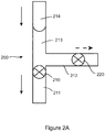
- Figure 2 shows such an example of a portion of a microfluidic device 200 comprising a first valve 210 in fluid communication with an actuation member 220, which may be provided by a second valve.
- Each of the first and second valves is located in a fluid channel 211, 212.
- the first fluid channel 211 provides a fluid spacer 213 provided upstream of the first valve 210.
- the fluid spacer in this configuration may be provided by a gas pocket and it serves to separate a dissolvable membrane of the first valve 210 from a liquid 214.
- Actuation of the actuation member 220 causes a retraction of the fluid spacer 213 by allowing a venting of the fluid (in this example a gas) through the now open actuation member 220 and away from the first valve 210.
- a venting of the fluid in this example a gas
- the volume of the fluid spacer was preventing the liquid contacting the valve 210
- a retraction of the spacer allows the liquid 214 to come into contact with the dissolvable membrane which effects an opening of the first valve.
- actuation of the first valve is controlled by actuation of the actuation member which is in fluid communication with the first valve.
- first valve may be fabricated in any one of a number of different ways such as those described with reference to Figure 1 above.
- the second valve may also comprise a dissolvable membrane which selectively dissolves on contact with a predetermined liquid.
- the present teaching provides a sequential opening of individual fluid channels within the microfluidic device and the selective control of the flow of a liquid within the microfluidic device.
- this opening of a first valve is effected without any additional third party or external stimulus.
- a passive control of sequential valve operation is achieved; the actuation of the actuation member serving to trigger the subsequent opening of additional valves within a microfluidic network.
- valves in fluid communication with one another to provide a variety of AND/OR relationships.
- a liquid released from activation of one valve can act as activation fluid for effecting opening of a second valve.
- This cascading behaviour can allow the valves to be networked in a manner such that the valves can be triggered in a defined sequence.
- bio-analytical methods such as immunoassays where sample and reagent wash steps are conducted in defined sequences.
- the valves can also be integrated into structures representing laboratory unit operations such as metering, mixing and decanting.
- Network relationship can also be implemented by defining the location of the control valves in fluid reservoirs. Parallel and almost simultaneous triggering of two valves can be achieved by positioning the two control valves so that they can each be triggered to open at the same time Similarly, an AND relationship can be implemented by locating a control valve relative to two or more valves provided upstream of the control valve, activation of the control valve requiring activation of each of the two or more upstream valves- an example of which is shown in Figure 2E .
- FIG 3 shows how a series of cascading valves, in this example two valves 300, 301, may be implemented in accordance with the present teaching.
- the valves 300, 301 are provided as part of a microfluidic device 302 which is incorporated on a rotatable substrate- not shown- which may be coupled to drive means which provide centrifugally induced artificial gravity conditions.
- the first valve 300 corresponds to the first valve 210 of Figure 2 whereas the 2nd valve 301 corresponds with the actuation member 220 of Figure 2 .
- the first valve 300 is provided within a channel 305 and serves to seal the channel when closed.
- the location of the valve defines an upstream 310 and a downstream 311 part of the channel; upstream and downstream being defined relative to the location of the valve within the channel 305.
- the upstream part of the channel comprises first 310a and second 310b branches.
- the first valve is desirably provided as a gas tight, liquid dissolvable film such as described above with reference to Figures 1 and 2 and may be considered a sacrificial valve.
- This valve 300 is connected to an outflow or receiving chamber 320. This may also be referred to as a release valve or outlet valve.
- the second valve 301 which serves as the actuation member is also provided initially as a gas-tight barrier and may be considered the control valve.
- this second valve also comprises a sacrificial membrane which dissolves on contact with a liquid but it will be appreciated that this type of sacrificial valve is not necessary for the control valve.
- Other actuation techniques could also be employed-for example the valve could simply rupture on increasing the pressure applied to the valve.
- a gas pocket 327 is provided immediately upstream from the first valve 300 and prevents liquid 325 from a fluid reservoir 326 coming into contact with the sacrificial membrane of the first valve 300.
- the gas pocket 327 extends through the first and second branches 310A, 310B and as such is in intimate contact with each of the first and second valves.
- the liquid termed in this example working liquid
- the working liquid cannot reach and thus dissolve and open the release valve 300 due to the counteracting pressure of the gas volume forming the fluid spacer.
- the working liquid cannot reach the release valve 300 through the presence of the pressurized gas in the gas pocket 327.
- a vent 312 to a large, unpressurized reservoir 313 or atmosphere is generated.
- the opening of the control valve 301 thereby changes the dynamic of the previous equilibrium between the fluid spacer and the liquid 326. Without changing any other variables in the system, this venting removes the counteracting force that was previously serving to prevent the working fluid progressing forwardly towards the valve 300 and actually allows the working fluid to reach the release valve 300.
- the opening of the release valve 300 there are two time constants governing the opening of the release valve 300.
- the first one can be freely programmed by selecting when the control valve 301 is opened which serves to effect a movement of the fluid spacer away from the release valve 300 and allow the liquid come into contact with the release valve 300. This then serves to trigger the opening of the release valve 300 and any delay is determined by the time taken to allow the liquid 325 move into contact with the sacrificial membrane of the release valve 300 and the dissolution time of the valve itself. As was discussed above with regard to the use of cellulose based wicking effect, by incorporating cellulose or some other wicking material this time delay can be increased.
- FIG. 5A shows another example where the control valve also incorporates a sacrificial membrane 501.
- This implementation may be considered an ancillary liquid activated valving mechanism.
- an ancillary liquid 525 is provided in a chamber 500 in fluid communication with the control valve 501.
- the rotation of the microfluidic device causes the ancillary liquid 525 to come in contact with the control valve 301 and opens it (from the backside).
- FIG. 5B shows an alternative configuration whereby the control valve 501 and release valve 300 are co-located and the ancillary fluid 525 is can flow through a channel 530 provided in a second layer of the device.
- the sacrificial membrane of the control valve 501 is located so as to face that 2 nd layer 530 such that flow of the ancillary fluid 525 through the second channel 530 effects a dissolving of the membrane and subsequent opening of the release valve 300.
- the ancillary liquid can also flow upstream through the control valve 501 where it may come into contact with the working fluid 325.
- mixing fluids may be useful. While not shown in the simplified schematic of Figure 6 , the mixing of two or more fluids could advantageously be provided by providing a receiving chamber 320 in fluid communication with a plurality of fluid paths provided upstream of the receiving chamber, each being selectively controlled by a control valve arrangement.
- the receiving chamber could also be provided in fluid communication with one or more fluid paths downstream of the receiving chamber 320 to allow the controlled release of a liquid (or mixture of liquids) within the receiving chamber to another mixing chamber downstream.
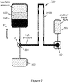
- a flow barrier 700 between the first 300 and second 501 valves In the event that it is not desired to mix the ancillary liquid with the working fluid such that only the working fluid 325 will flow into the receiving chamber 320 it is possible to provide, in accordance with the present teaching, a flow barrier 700 between the first 300 and second 501 valves.
- Figure 7 shows such an example where the second branch 310B is configured to define a flow barrier between the two valves. This flow barrier prevents liquid to pass from one side to another. The barrier is arranged to allow an exchange of gases so as to equalise the pressure within any open micro-channel.
- the orientation of the second branch 310B is configured to define a tortuous path.
- a tortuous path is a siphon shape which extends radially inwards on a centrifugal disk.
- the pressure exerted by the liquid upstream of the branch 310B is not sufficient to overcome the necessary head pressure to travel around the siphon and mixing is prevented.
- the barrier is a membrane which is gas-permeable but impermeable to the working liquid.
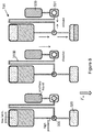
- Figure 8 shows a sequence that will follow the opening of the control valve.
- the ancillary liquid comes in contact with the control valve.
- the control valve is dissolved which permits the working fluid to reach the release valve.
- the release valve is opened and opens a path for the fluid to the receiving chamber.
- the barrier 700 prevents the working liquid from exiting through the control valve or mixing with the ancillary liquid.
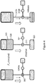
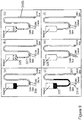
- Figure 9 shows another schematic illustrating operation of a microfluidic device incorporating cascading valves in accordance with the present teaching.
- a fluid is loaded in reservoir 326.
- centrifugal force are generated and as shown in Figure 9b , under the influence of this centrifugation, the fluid is compressed into the pneumatic chamber until equilibrium is reached. Below a certain threshold frequency, the gas will not be sufficiently compressed to allow the fluid to reach the sacrificial or release valve.
- Figure 9c illustrates the result of an opening of the control valve, either to atmosphere or a large reservoir.
- the liquid can advance to contact the sacrificial release valve, shown in Figure 9e .
- the release valve dissolves and allows the fluid to drain through the outlet channel 311 and as shown in Figure 9f , the reservoir 326 is fully emptied through the outlet channel.
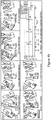
- Figure 10 shows a system schematic of a how the previously described exemplary arrangement of two cascading valves may be extended to a system comprising more than two valves sequentially arranged to allow actuation of a first valve effect a triggering of a second valve to open.
- a microfluidic structure showing two reservoirs 1001, 1002 and two collection chambers 1003, 1004 each separated by valves 1005, 1006, 1007, 1008.
- liquid is loaded into each of the two reservoirs 1001, 1002.
- Figure 10c liquid is loaded into the chamber containing the first control valve 1005 and the disk is centrifuged.
- a liquid path to the first collection chamber 1003 is now open.
- the first collection chamber 1003 starts to fill.
- the second control valve 1006 can then be opened as shown in Figure 10h with the result show in Figure 10i that the liquid in the second reservoir 1002 has an open path and comes in contact with the second release valve 1008.
- the contact causes this valve 1008 to dissolve ( Figure 10j ) with the result that the liquid has a free path to enter the second collection chamber 1003 ( Figure 10k ).
- Figure 10i in the absence of any restriction in the fluid paths, the fluid will now drain completely into the second collection chamber 1004.
- devices comprising two or more valves may be provided with each of the valves having different operating characteristics.
- valve actuation of a specific valve may be judiciously related to a frequency of rotation of the device, it is possible in accordance with the present teaching to provide multiple valving arrangements with actuation of specific valves being controlled by the spin frequency of the disc / rotor. In this way frequency thresholds can be introduced, and one or more reagents stored within the device can be slated to enter the reaction at a later stage and can be held back even through vigorous, high-frequency rotation and acceleration of the device as a whole.
- a valving system provided in accordance with the present teaching addresses many problems associated with providing point-of-care bio-assays in an on-chip implementation. There is a desire within the context of providing such devices for a system that will allow for a storage and sequential release of sample and liquid reagents (the equivalent of multiple pipetting steps at the benchtop).
- Typical implementations are cell-based assays, dilution series and immunoassay protocols.
- these assays are implemented based on valving techniques which can be divided into those actuated off disk - such as thermally activated phase-change valves - and those which are actuated by changing the centrifugal forces on the disk (by changing the velocity of rotation).
- valves examples include burst valves, capillary siphons, pneumatic siphons and dissolvable film valves.
- burst valves In order to open these valves in the correct centrifugal force profile is required by implemented a predefined velocity profile.
- the limitations on the upper and lower velocity profiles can limit the number and location of valves. For example serial siphons - actuated through a decrease and then increase in disk RPM - can take up significant space on a disk.
- opening of a first valve triggers the opening of a second valve without any other changes in the system dynamic required.
- first and second valves arranged in a cascade sequence can be expanded to more complex arrangements.
- a sequential release valve may be opened through fluid being absorbed and then transported from a location away from the sacrificial valve to a location near the sacrificial valve through use of an integrated absorbing material provided within the microfluidic network.
- This material could be one of a number of different types of material- for example it could be paper or another cellulose based material and could be affixed to the actual valve or alternatively provided in fluid communication with the valve.
- the material may be used to transport fluid to a reservoir near the valve and then allow a subsequent opening of the valve. In this way the absorptive material may be used to place a significant time delay between the wetting of the absorptive material and the opening of the valve through a dissolving of the sacrificial membrane.
- a second principle that may be considered is a method whereby a sequential release valve is used to hold fluid (called pumping fluid) in a reservoir at a point on a disk.
- pumping fluid fluid
- working fluid fluid
- the pumping fluid flows radially outward due to centrifugal force and through displacement of the working fluid (or gas which subsequently displaces the working fluid) causes some part/all of the working fluid to be displaced significantly radially inward.
- the microfluidic network will incorporate fluid paths that direct fluid flowing outwardly from an axis of rotation of the device-in accordance with the induced centrifugal force.
- This pumping fluid may be immiscible with the working fluid and/or have a greater density than the working fluid.
- a centripetal displacement of the fluid may be used to prime a siphon valve
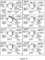
- FIG. 11 An example of how fluid paths that direct flow contrary to an induced centrifugal force is shown in Figure 11 which will be appreciated is a specific example of an general technique that can be provided in accordance with the present teaching.
- Figure 11 details four different panels, each showing the fluid location at different times.
- a reservoir 1100 is provided and used to retain a material/substance/apparatus 1105 which, when coming in contact with a fluid, results in an increase in the material/structures volume such that the net volume of the fluid/apparatus increases.
- the material is baking powder but other alternative materials such as for example non-oxidised metal particles, for example Boron could also be used.
- a liquid reservoir 1110 comprising a liquid 1115 is provided in fluid communication with the reservoir 1100 and also with first 1120 and second 1125 valves.
- a series of chambers may be provided and arranged relative to one another such that different sources of fluid expansion may be provided which can then occur at different rates resulting in actuation of the valves/pumping processes in sequence.
- different sources of fluid expansion may be provided which can then occur at different rates resulting in actuation of the valves/pumping processes in sequence.
- stagger the timing of the fluid coming in contact with the material/apparatus in order to stagger the activation of the valves (i.e. material located behind a dissolvable film).
- the generated gas may be trapped behind a deformable membrane and used to displace a secondary fluid.
- the material chosen within the reservoir may determine the timing of the actuation of the valve and the actual volume of gas that may be generated with the resultant pressure increase.
- the volume of the reservoir 1105 is used to determine the timing of the actuation of the valve.
- actuation of the valve is triggered through increasing/decreasing the speed of the disk rotation such that fluid comes in contact with the material. It will be appreciated that all or none of these actuation techniques may be implemented together.
- sacrificial valves may be initially provided within the microfluidic device having a gas pocket provided between the liquid and the valve.
- the presence of the gas pocket defines a fluid barrier preventing liquid contact with the valve.
- the retention of a gas pocket is advantageously enabled within the context of the present teaching as the channels of the device are microfluidic in nature.
- the present teaching does not require the frequency of rotation of the rotatable substrate to be increased to effect the opening of these valves.
- the present teaching provides an opening of a valve based on parameters related to both the time required to dissipate the gas pocket away from the sacrificial membrane and the dissolution rate of the membrane on contact with the liquid. This redaction of the fluid spacer provided by the gas pocket is not effected by increasing the rotation frequency of the rotatable substrate but rather by actuation of another actuation member in fluid communication with the sacrificial membrane valve.
- the time required to dissipate the gas pocket will depend on the volume of gas in the gas pocket which is related to the dimensions of the channel housing said pocket. It will be understood that within the context of the present teaching that it is the micro-dimensions of the microfluidic device that allows the creation of a stable gas pocket in the first place.
- the first region of the channel in the location upstream of the sacrificial membrane it is possible to ensure that once the device is primed a gas pocket will be formed between the sacrificial membrane and the advancing fluid within the first region. Effectively the introduction of a liquid into an entry port of the first region allows the liquid to advance within the first region. The advancing liquid migrates through the first region forcing gas forwardly of fluid.
- the gas will migrate towards the sacrificial membrane.
- the nature of the sacrificial membrane is such as to provide at least a time delay in gas migration through the membrane.
- the membrane will be gas impermeable preventing the passage of any gas through the fabric of the membrane.
- the membrane will provide a flow resistance whereby gas may over time percolate through the fabric of the membrane. In both circumstances, the membrane retards or stops completely the progression of the gas past the valve so as to ultimately form the gas pocket between the sacrificial membrane and the advancing fluid within the first region.
- the volume of the gas pocket will have an effect on the time duration that will ultimately be required to dissipate the gas away from the sacrificial membrane and allow liquid contact the membrane.
- the principle in use by which the gas pocket dissipates may vary dependent on the configuration employed but in accordance with the present teaching in all circumstances is triggered by the actuation of a valve provided in fluid communication with the sacrificial valve.
- a valve provided in fluid communication with the sacrificial valve.
- the time of actuation is dependent on the actuation time of the actuation member, the rate of breakdown of the gas pocket and the subsequent dissolving rate of the valve. It will be appreciated that such a configuration is particularly useful for on-board reagent storage.
- the sacrificial membrane is selected to have specific vapour resistant properties. The significance of this resistance will however depend on the specifics of the intended storage conditions.
- a valving arrangement in accordance with the present teaching it is possible to provide a liquid-gas interface within the device by the retained gas pocket and the liquid within the first region of the channel. It will be understood that this interface is effectively stable and will remain in-situ in the absence of an applied force to disrupt that stability.
- the stability is governed at least partially by the geometry and surface tension between the two adjacent fluid (liquid and gas) phases and is triggered by actuation of an actuation member, typically formed by a second valve, in fluid communication with the sacrificial valve.
- an actuation member typically formed by a second valve
- the gas pocket is operably retained in place between the advancing fluid and the valve and will remain in place until such time as the pressure pressing the liquid plug against the gas pocket supersedes a certain critical value.
- operably destabilizing the meniscus such as for example by providing elevated pumping pressures and reducing the pressure downstream of the valve it is possible to bring the fluid into contact with the valve, effectuate the wetting and following dissolution of the valve.
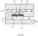
- the present teaching provides a multilayer microfluidic device comprising first 201 and second 202 channels provided in first 201A and second 202A layers of the multilayer microfluidic device 205.
- Each of the first and second channels is in fluid communication with one another through a vertical through-hole 203.
- a sacrificial valve 100 is provided within or adjacent to the through-hole and in a normally closed configuration serves to prevent passage of a liquid through the through-hole. By selectively opening the sacrificial valve it is possible to allow the flow of a liquid from the first channel to the second channel.
- the first and second channels are desirably configured within the microfluidic device such that on opening the sacrificial valve, a liquid travelling in the first channel 201 will preferentially go through the through-hole 203 and into the second channel 202.
- the sacrificial valve 100 is desirably of a type such as described above with reference to Figure 1C and comprises a sacrificial membrane 102 and is desirably configured to selectively dissolve dependent on the specifics of the liquid contacting the valve.
- a liquid specific membrane it is possible to sequentially flow different liquids passed the valve and the valve will only open when exposed to a specific liquid which targets the specific sacrificial membrane utilised.
- certain membranes may have hydrophobic properties which do not dissolve on exposure to an aqueous solution.
- Other membranes may be selected for the hydrophilic properties such that they will dissolve on contact with an aqueous solution.
- the sacrificial valve 100 comprises a thin film structure. This may be provided as a single layer of a dissolvable film.
- the dissolvable film may be provided as an aqueous polymer matrix comprising one or more of various cellulose derivatives, hydrocolloids, acrylate copolymers, gums, polysaccharides, plasticizers or the like.
- a multi-layer functional film configuration may be utilised to fabricate a valve.
- Such a multi-layer contract may incorporate individual layers with different properties.
- a first layer may be hydrophobic whereas a second layer is hydrophilic.
- the hydrophobic layer may resist dissolution by water and as such will retain the integrity of the valve despite passage of an aqueous solution passed the valve.
- individual layers of the valve may be dissolved dependent on the nature of the solvent in the liquid passing the valve.
- the timing of the opening of the valve may then be controlled by judiciously selecting a valve whose individual layers match the sequence of fluid flows desired for a particular assay.
- Such a multi-layer construct may comprise a first layer comprising a pressure sensitive adhesives film (PSA films) 101 and a second layer of a dissolvable film 102 which may be adhered to or otherwise provided on the PSA.
- PSA films pressure sensitive adhesives film
- the PSA film may be provided as a single sheet which is outlined with through holes cut using a cutter-plotter machine.
- the secondary layer consisting of a specialized dissolvable film may then be pressed on the PSA. These tabs are then cut from the complete assembly.
- valves Embedding the assembly within the channel of the microfluidic device creates the valves; the tacky nature of the PSAs allows for closing off microchannels by simply sticking the assembly into the system features.
- the valves remain isolated; the valve is essentially in a "closed state” until liquids come into contact with the dissolvable film surface. Once liquids are pumped to the interface, after a determined period of time the film liquefies and the valve is in an "open state", further pumping will propel liquids through the valve site.
- the use of the hybrid films for valving has applications for a range of microfluidic designs including both stationary and centrifugal arrangements.
- centrifugal based systems are notably improved by dissolvable-film based valving; for example mixing, blood separation, metering, aliquoting, phase separation, dilution, on-board liquid storage, etc.
- valve comprising dissolvable films to form efficient barriers for liquid flow; until the films are in direct contact with liquid reagents the fluidic seals between regions of the device are fully maintained. No separate actuation of the valve is required as the same pumping mechanism driving the flow also actuates the valve.
- the sacrificial valves described here are of particular interest for a range of applications; for example as programmable flow control elements and as vapour barriers for on-board liquid reagent storage.
- a first fluid flow of an aqueous solution will have no effect on the integrity of the valve- the aqueous solution not effecting dissolving of the top layer of the valve.
- an organic solution such as IPA/EtOH it is possible to then effect a dissolving of the valve such that the liquid flow will pass through the through-hole 203 and into the second channel 202.
- Such a valving arrangement is particularly advantageous for stop-go liquid-based assay devices which use a plurality of liquids in a predetermined sequence of steps to achieve a particular analysis.
- a solvent based routing arrangement may be used in a variety of applications.
- use of such valves provides for a redirection and separation of consecutive aqueous, organic and/or mix flows. In one arrangement this may be used to facilitate nucleotide purification (total RNA) from whole blood using a centrifugal microfluidic platform, on which the two valving systems are integrated
- valve 100 In a first configuration the valve 100 is located within a valve seat 204 and is connected through a channel 203 which has a cross-sectional area greater than the cross sectional area of the first 201 region.
- a fluid is provided in a first region of the channel 201 upstream of the valve 100, the valve providing a barrier to fluid flowing into the second channel.
- the microfluidic device may be coupled to a drive mechanism configured to induce fluid flow in the fluid which operably drives the fluid towards the valve. On contact of a specific fluid with the valve, the valve dissolves and the fluid may then pass from the first to the second region.
- a layering of hydrophobic membranes and dissolvable films within a multi-layered valve provides a tuneable valve whereby the flow of a specific fluid type over the valve can be used to change the properties of the valve.
- the layering is:
- an initially aqueous solution will flow over the valve primarily because the membrane is hydrophobic and only secondarily because there is gas trapped in the pockets (the ⁇ 0.3 ⁇ m pits in the track etch membrane).
- the second fluid to pass over - IPA - will wet the membrane and changes its surface properties. Due to the changed properties a third fluid - aqueous - will also wet the membrane and come in contact with the dissolvable film. This will result in the fluid dissolving the dissolvable film and routing through the fluid.
- the valve may typically be provided below a step 204 to ensure that the valve 100 does not stand too high as this can deviate or block the flows to the lower channel 202.
- a hydrophobic (PTFE) 103 membrane on the top side of the PSA layer 101 lies a hydrophobic (PTFE) 103 membrane.
- the membrane is covered with a second PSA layer 101 and a water soluble film 102 on the top of this stack.
- Figure 12B shows an example of another complex analysis that may be achieved using cascading valves including at least one multi-layer valve in accordance with the present teaching, specifically a system configured to provide for solid phase nucleotide extraction on glass beads from cell homogenate and crude extract from whole blood.
- a microfluidic network 1200 of channels may be fabricated on a rotatable substrate 1201.
- the substrate has an axis of rotation 1202 and as will be appreciated by those of skill in the art, a rotation of the disc will causes fluid located proximal to the axis of rotation 1201 outwardly towards a perimeter 1203 of the substrate in a direction following the arrow.
- a reservoir 1205 of glass beads is provided.
- the reservoir is coupled to four different fluid inlets: 1206, 1207, 1208, and 1209. These four inlets allow for the sequential introduction of an aqueous solution comprising RNA, IPA, EtOH and water through each of channels 1206, 1207, 1208, 1209 respectively.
- a first valve 1210 is provided downstream of the reservoir 1205.
- This valve is desirably provided of the type described above as a combo-valve and shown in detail in Figure 1C .
- the combo-valve is provided in fluid communication with a second valve 1211 via a flow restrictor 1213- the flow restrictor is provided by a tortuous fluid path generating a siphon similarly to that described above with reference to Figure 7 .
- the second valve 1211 desirably also comprises a sacrificial film.
- the two valves are provided in a closed configuration.
- the aqueous RNA solution is introduced through fluid path 1206 into the chamber 1205 with the glass beads.
- the aqueous phase is pressure driven over the combo-valve 1210- see Figure 1C for detail.
- the water in this fraction dissolves the first layer of the valve and stays on top of the PTFE membrane.
- Above a certain angular velocity the pressure exerted by the siphon 1213 against the flow of liquid is overcome by the centrifugal forces and the liquid flows into and comes into contact with the second valve 1211, thereby dissolving the soluble sacrificial membrane of this valve.
- a configuration incorporating a vertical stacking arrangement whereby the sacrificial membrane is located in a plane substantially perpendicular to the direction of the induced centrifugal force facilitates manufacture of complex valve arrangements.
- Using such a stack arrangement it is possible to include other materials within the valve structure. Examples include functional membranes which may be integrated in the same way without significantly increasing the complexity of manufacture.
- the destruction of dissolvable layer occurs at a frequency of rotation of the device- herein referred to as the burst frequency.
- Such features are an improvement on the centrifugal platform as valving technologies that can withstand very vigorous hydrodynamic conditions enable processing (radially) above the valve while preserving downstream functionality.
- the retention of the valves at such high-speeds shows potential for storing and withholding reagents throughout a series of spin protocols and opening on-demand at key operational times. This would be useful in such applications like clinical diagnostics where high-speed centrifugation is necessary for plasma separation from whole blood or vigorous mixing and homogenization steps.
- Valves retaining the regents/buffers required to analyse or process the components remaining in the supernatant would be capable of holding until after the blood components are separated.
- Microfluidic devices incorporating valves within the context of the present teaching are also useful for bioassays, e.g. immunoassays in clinical applications.
- the mixing reservoir may be provided with a phase change material such as a material which is solid at room temperatures and becomes a fluid (lighter than water) at elevated temperatures.
- a suitable material is paraffin or a wax.
- the use of the sacrificial layer valve represents a significant improvement on prior art efforts to provide mixing on a centrifugal platform as high-speed rotation can be performed without hindering other processes (as opposed to traditional passive valving techniques which can only withstand up to ⁇ 1000 RPM).
- the dissolvable film technology could be used in blood separation.
- whole blood is introduced in a chamber on the disc.
- a valve provided within the context of the present teaching is placed at the end of an exit channel connected to the blood separation chamber.
- a "slowly dissolving" film layer which takes minutes to liquefy, will be in contact with whole blood during centrifugal sedimentation (under high speed sedimentation the process takes about 3 min).
- the pure, separated plasma which would have been in contact with the valve, liquefies and thus opens the valve. Further pumping will propel the pure plasma through the valve site for further processing on the disc.
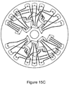
- Figure 12C shows a further arrangement provided in accordance with the present teaching.
- HMV Hydrophobic Membrane Valve
- DV dissolvable film
- the device illustrated in Figure 12C displays four distinct chambers: for loading of the solid phase and reagents (chamber L), for the aqueous waste (W aq ) in the first, for collecting the organic waste (W org ) in the second and third and for eluting the extracted RNA (E aq ) in the final step of the solid-phase extraction protocol.
- chamber L for loading of the solid phase and reagents
- W aq aqueous waste
- W org organic waste
- E aq eluting the extracted RNA
- valves were assembled into a tab structure using two pieces of PSA - as was previously described with reference to Figure 1 .
- the first was a Dissolvable Film Valve (DFV), which resists organic solvents, i.e. it would not dissolve during two of the four extraction steps, i.e. in the presence the IPA and EtOH.
- the second valve was a Hydrophobic Membrane Valve (HMV), which permitted the passage of the organic phase but remained impermeable to water. This single-use DFV opened once in contact with water whereas the HMV remained intact preventing water from passing through.
- DFV Dissolvable Film Valve
- HMV Hydrophobic Membrane Valve
- the router utilizes four valves (HMV, siphon valve, DFV and HM) with different functionalities.
- the Hydrophobic Membrane (HM) at the outlet of the aqueous waste serves two roles; first, it acts as a selective barrier to prevent the solution from flowing out of chamber 4, and secondly it acts as a vent.
- the frequency actuated siphon valve permits the aqueous fraction to pass and to restrict the IPA and EtOH, minimizing the risk of contamination with organic solvents.
- RNA depleted fraction was directed through a siphon valve into an aqueous waste chamber (W aq ).
- RNA aqueous elution reservoir E aq .
- the solvent specific valves permitted a separate collection of the purified RNA containing a fraction from the aqueous and organic waste. It will be appreciated that this is an example of a stop-go assay that may be provided in accordance with the present teaching.
- Figure 12D shows an example of how the present teaching may provide routing of different fluids.
- a simple, "inverse-Y” structure comprising a loading chamber connected via a bifurcation to two outlet chambers is provided.
- the 3-dimensional (3D) architecture of these multi-layer discs allows different channels to be provided in separate layers and be connected via a vertical through hole sealed using one of the solvent-selective valves; in this case a HMV.
- HMV solvent-selective valves
- the liquid would preferentially travel to the left collection chamber due to the lower flow resistance of this pathway.
- the HMV remained impermeable to aqueous solutions, thereby routing the flows to the right collection chamber.
- the valve technology of the present teaching can also be used for implementing a dilution function.
- the valve is placed in a pneumatic chamber connected to the dilution chamber. After adding dilution buffer to the sample in the dilution chamber, the diluted sample is propelled into the pneumatic chamber where it liquefies and opens the valve. Further pumping thus propels the liquid through the valve site for further processing.
- the valve is used to carry out a complete assay on a centrifugal microfluidic platform.
- the valves are sequentially placed at different positions on the disc where it is first used for blood separation, then mixing of reagent buffer and plasma extracted from whole blood.
- the reagent buffer and plasma are allowed to incubate. After incubation, they are propelled to the optical detection region, where incubation with capture antibody and optical detection occurs.
- valve placed in a pneumatic chamber connected to the liquid storage chamber provides both liquid and vapour barrier to the stored liquid.
- the liquid is stored in this chamber for as long as necessary, e.g. during shelf life.
- the disc is spun at the burst frequency of the pneumatic chamber; this releases the liquid into the pneumatic chamber where it liquefies the valve membrane. Further pumping propels it through the valve site for further processing.
- DF valves in accordance with the present teaching can be configured to yield at a geometrically well-defined burst frequency which can be tailored over a wide range of spin rates by the radial position of the valve on the disc, the volume of the entrapped air in the pneumatic compression chamber and the length of their inlet channel.
- burst frequencies Due to the broad range and sharp definition of burst frequencies, the present inventors have integrated and automated a comprehensive multi-step, assay protocol including the sequential release of 4 reagents by merely rotationally actuated dissolvable-film (DF) based centrifugo-pneumatic valving scheme.
- DF dissolvable-film
- valve comprising dissolvable films to form efficient barriers for liquid flow; until the films are in direct contact with liquid reagents the seals between regions of the device are fully maintained. No separate actuation of the valve is required as the same pumping mechanism driving the flow also actuates the valve.
- the sacrificial valves described here are of particular interest for a range of applications; for example as programmable flow control elements and as vapour barriers for on-board liquid reagent storage. Within the context of the present teaching it will be appreciated that it is the direct contact of the liquid with the membrane that causes the rupturing of the membrane. The liquid does not flow through an already opened valve; the liquid causes an opening of the valve.
- the gas pocket which is initially provided between the liquid and the membrane delays the contact of the liquid with the membrane.
- the increase in pressure of the gas during the actuation process may cause a stretching of the membrane, but it does not necessarily effect a breaking of the membrane.
- the device is configured such that before the membrane is stretched to a breaking point, the gas is displaced away from the membrane allowing the liquid to come into contact with the membrane and effect the opening of the fluid passage way between the two sides of the valve.
- the stretching of the membrane may shorten the time period which the liquid needs to be in contact with the membrane to effect a dissolving of the membrane, but liquid contact is required.
- the valving tabs can be premade and placed into the system at multiple points along the fabrication/assembly of a device. As opposed to methods like wax valving no special machinery is needed to keep waxes at liquid temperature for dispensing. Also (moderate) heating of the device, e.g. for running thermally controlled reactions, would be possible without compromising the integrity of the valves.
- the rotational control of the sample liquid itself is the mechanism for actuation.
- no special machinery e.g. to heat the waxes for actuation.
- the actuation is implemented by the same actuator which propels the liquid through the microfluidic chip, e.g. a pump or a centrifugal field.
- a valving arrangement which can be usefully employed to provide an arrangement of metering valves and microchannels which can be used to assay m*n sample/reagents on a disk.
- Such applications may be advantageously used in the context of biomedical applications such as genotyping and drug discovery.
- a microfluidic network is provided on a substrate which is arranged to be rotated.
- a substrate may be provided in the form of a cartridge or disk and, as a result of the induced forces arising from a rotation of the substrate, a fluid is pumped radially outward and may become trapped and metered in structures with an outlet at the base.
- This method may be implemented in arrangements whereby the mixing reservoir is vented to atmosphere or closed to atmosphere. It also can be provided in scenarios where multiple mixing reservoirs are present on a chip. In such an implementation each mixing chamber may be fed by at-least two metering/valving structures.
- Figure 13 An example of such a configuration is shown in Figure 13 which exemplifies a valving arrangement which is configured to provide a combined metering and aliquoting of a liquid from a metering chamber 1300 to a sample chamber 1301.
- the metering chamber is provided immediately upstream of a valve or some other flow control 1303 provided in a fluid sample channel 1302.
- the fluid sample channel 1302 may be provided as a branch off a main fluid channel 1304. In this way a liquid passing in the fluid channel will collect in the metering chamber 1300 and will be retained therein until such time as the valve is opened.
- the dimensions of the metering chamber will define the ultimate volume of liquid that is subsequently aliquoted from the metering chamber to the sample chamber.
- this configuration of the present teaching provides a valving arrangement which may incorporate a cellulose/ paper-based or membrane-based metering structure for use on a centrifugal microfluidic lab-on-a-disc platform.
- a valving arrangement which may incorporate a cellulose/ paper-based or membrane-based metering structure for use on a centrifugal microfluidic lab-on-a-disc platform.
- a finite volume of liquid may be allowed collect in a metering chamber upstream of the valve. Opening the valve allows the flow of this metered volume to a sample or mixing chamber located downstream.
- a sacrificial membrane such as paper or a hydrophobic membrane which absorbs and holds back the liquid up to a certain pressure barrier
- the properties of the membrane can be used to determine the time of opening of the valve. For example, by increasing the spinning rate the disk is subjected to, the liquid can be forced through the paper/membrane and into a mixing chamber.
- the metering chamber is located closer to the axis of rotation of the disc than the mixing chamber such that when the valve is opened the rotation of the disc induces a fluid flow from the metering chamber to the mixing chamber.
- the device is provided as a multi-layer microfluidic device comprising first 1304A and second 1304B fluid channels provided in different layers of the device.
- the fluid channels are configured relative to one another to provide a combined metering and aliquoting arrangement such that a first and second metered sample provided from each of the first and second fluid channels may be directed to a common mixing chamber 1301 for use in an assay.
- FIG. 13 illustrates the example of how a microchannel 1304 connects two reservoirs- not shown. Fluid is pumped from one reservoir to the other via centrifugal force. At a given point in the microchannel the fluid comes in contact with a paper tab 1303. This paper tab has been partially exposed to the fluid. A certain amount of liquid is absorbed (as a function of the paper's absorbance, the fluid's time in contact with the paper, the surface area of the paper which is exposed and the entire size/volume of the paper tab) and then retained in the tab. The remaining volume of fluid continues to the lower reservoir leaving a defined volume of fluid in the tab.
- the rate of spin rate is increased such that the paper tab can no longer retain the volume of fluid through absorbance.
- the fluid wicks from the paper into a shaped microchannel and then into a container 1301.
- microchannels/paper tabs in multiple layers are configured such that two or more paper tabs interface with a mixing reservoir with liquid under centrifugation conditions. Therefore a liquid sample or reagents can be discretised such that elements of M fluid samples can be mixed with N reagent elements to make M*N sample-reagent mixtures.
- the microchannels contain small catchment structures 1300 which retain a specific volume of fluid.
- a porous membrane (hydrophobic or hydrophilic) or absorptive material such as paper
- the centrifugal force is insufficient to force the fluid through these membranes.
- the fluid is driven through these membranes or absorptive material such that a substantial portion of the fluids enter a mixing chamber 1301
- the metering volume 1300 may be pre-loaded with a (possibly immiscible) liquid which is less dense than the mixing liquids. At low centrifugation rates surface tension is sufficient to prevent the assay liquid entering the mixing chamber. However at higher rates the density difference between the sample/reagent liquids and the pre-loaded fluid results in the fluids inverting and the sample/assay re-agents entering the mixing chamber.
- one or more of the individual mixing chambers can be pre-loaded with a material which undergoes a phase change (sold to liquid) at low temperatures ( ⁇ 60 C), e.g. a paraffin.
- This material can be used to prevent fluids entering the metering structure but upon a phase change inverts with the fluids and allows them to mix.
- dissolvable solid or gel which substantially occupies the mixing chamber and prevents the liquids from meeting. This dissolvable solid/gel can also be part of the reaction - a jellified PCR reagent for example.
- microchannels may follow paths that do not run parallel to or are synced with the direction of rotation of the substrate.
- the microchannels may be formed in a spiral/reverse spiral format.
- the microchannels are provided in a microwell plate based configuration. Using a 96 Well format could allow 48*48, 24*72 etc. A 384 well format could allow 192*192; 2 by 96*96. This could also be configured into the same form factor as a conventional microwell plate by rotating from different axes.
- microfluidic device such as that shown and described above in a multilayer arrangement it is possible to fabricate a microchannel which moves between layers to avoid intersection.
- a complex network of individual microchannels and controlling the flow of a fluid through this network through a use of a cascading valve structure it is possible to provide an accurate metering system for controllably metering individual volumes of a fluid to a desired location at a desired time.
- Such an assembly may be implemented using a metering structure which is fed by valves which allows a controlled flow of a liquid through the device.
- a fluid may be bifurcated/discretised, bifurcated again and once in small enough elements mixed per predefined assay protocols.
- Such a complex network may include a plurality of mixing reservoirs. Each of the reservoirs may be fed by one or more single sources.
- a mixing arrangement on a single rotatable substrate may be provided for m-samples, n-primer/probes and a single source of Taq polymerase master-mix).
- loading cartridges or inlets for the chambers are arrayed at a pitch similar/identical to commonly used micro-titre plates (9mm or 3.5mm pitch).
- a cellulose material may be incorporated into one or more of the individual microchannels and then used as a metering structure.
- a fluid flows over the cellulose material and a discrete volume is absorbed.
- the excess fluid flows on to the next metering structure/waste. Increasing the rate of centrifugation forces the fluid downwards through the paper and into the mixing reservoirs.
- the membrane may be formed from a variety of materials such as cellulose or paper based material. Any other absorptive material could also be used. It is also possible to utilise the properties of a hydrophobic or hydrophilic membrane.
- the small pore sizes of these membranes (typically in the range 0.1 um-5um or 5um-50um) provide the valve with a well- defined, and increased, flow resistance compared to an open channel or typical capillary burst valve used on conventional centrifugal microfluidics. These increased burst frequencies mean the valves will not burst until the centrifugal force is increased significantly. This large step-change ensures that the typical dependency of capillary burst valves on radial location on a disk is mitigated.
- a dissolvable film separating it from the mixing reservoir.
- a pneumatic pocket may be provided which functions to prevent the dissolvable film from coming into contact with the fluid at specific RPMs. By increasing the RPM it is possible to force the fluid into contact with the dissolvable film valve, removing it and allowing the liquid to flow into the mixing reservoir ( Figure 14 ).
- the metering structure as an overflow structure with a dissolvable film separating it from the mixing reservoir.
- the dimensions of the chambers are selected such that the fluid has sufficient time to fill the metering structure and overflow before the dissolvable film dissolves and allows the fluids to enter the mixing reservoir.
- Such an arrangement may be provided without any change in the dynamic forces applied to the device- for example without any increase in RPM of the disk.
- the present teaching also provides an arrangement where no membrane is used and the mixing chamber is pre-loaded/filled with an immiscible fluid/material.
- an immiscible fluid/material is lighter than aqueous/water.
- Choices for such an immiscible fluid include an oil.
- the oil advantageously prevents evaporation of the sample fluids once in the mixing chamber or results in improved mixing of the reagents due to the merging of aqueous droplets in an oil background. This may be particularly advantageously employed in techniques such as PCR genotyping or qPCR for screening.
- the above disclosure provides exemplary arrangements of a rotatable microfluidic device provided on a centrifugal platform and configured to selectively direct liquids through a predetermined path using one or more valves.
- the device comprises a first valve in pneumatic communication with an actuation member that functions as a control valve of the device.
- the device is configured such that actuation of the actuation member effects a retraction of a gas spacer provided in front of, or, upstream of the first valve to allow a liquid come into contact with and dissolve the first valve.
- this actuation of the actuation member and the subsequent dissolution and opening of the first valve can be event triggered so as to allow for cascading events which mirror a predetermined number of steps in an assay.
- This sequential opening provides for a selective control of the flow of a liquid within the microfluidic device.
- a plurality of individual valves may be provided on the same device and individually actuated dependent on certain parameters or conditions being met.
- valves are pulse actuated in response to changes to the rotation frequency of the rotatable device or disc.
- timing of the valve actuations is governed by the nature of the valve, i.e. the materials from which they are made and their orientation within the overall disc architecture, while the time at which the valves actuate is governed by changes in disc spin rate.
- disc spin rate By placing a plurality of valves in series, it is possible to use the disc spin rate to trigger valves.
- a valving arrangement comprising a pneumatic chamber sealed by both a control valve and a release valve.
- the release valve could comprise a dissolvable membrane - similar to that described previously.
- the membrane may be recessed in a dead-end chamber and with the control valve provided in an initially closed configuration, liquid cannot enter the pneumatic chamber sufficiently to wet and dissolve the membrane.
- the valve in effect becomes a burst valve where the membrane will not be wetted unless the spin rate increases above a critical frequency.
- opening the control valve puts the release valve in an openable state, or at least primes the release valve. Unless these two parameters are met (control valve opened and the disc rotating above a critical spin rate) the release valve will not open. In this way rotating the disc at a pulsed rotation rate can be used to selectively actuate individual ones of the valves.
- Figure 19 shows in schematic form such an example whereby a plurality (three) valving arrangements are provided - each of the three valving arrangements featuring a control valve and a release valve. With both valves sealed the liquid will not contact and open the dissolvable films of the valves at any typical disc spin rate. When the control valve is opened below a typical spin rate the release valve will not open. However, with the control valve opened, increasing the disc spin rate will effect opening of this release valve. It is clear from the timing sequence of Figure 19 that by pulsing the rotation rate of the disc individual valves can be actuated.
- the rotatable disc is configured to implement event-triggered flow control.
- Such an arrangement may include a pneumatic chamber provided between a restrained liquid and a release valve incorporating a dissolvable film, in the form for example of a classical siphon geometry. With a control valve sealed, the liquid cannot enter the pneumatic chamber and dissolve the dissolvable film at any spin rates. Similarly, with the control valve opened and the disc spinning above a critical frequency, the centrifugal force is sufficiently strong to prevent siphon priming. Similarly to that described above with respect to the high-pass configuration by reducing the spin rate at this point it is possible to prime the siphon-based valve where the control valve opened but any siphon valve with an intact control valve will not be primed.
- the actuation of the valves may be timed to be coincident with rising and falling edges of a pulse signal which changes the rotation rate of the disc on which the valves are provided.
- the increase in rotation or spin rate of the disc can be considered as being achieved by increasing the spin rate from a low level to a high level, analogous to a rising edge.
- the present teaching provides a valving arrangement comprising a selective actuation mechanism facilitated by the sequential passing of different liquids passed the valve.
- the present teaching provides a multilayer microfluidic device comprising first and second channels provided in different layers of the device, each of the first and second channels leading a common destination and providing an integrated metering and aliquoting arrangement.
Landscapes
- Chemical & Material Sciences (AREA)
- Engineering & Computer Science (AREA)
- General Engineering & Computer Science (AREA)
- Dispersion Chemistry (AREA)
- Health & Medical Sciences (AREA)
- Mechanical Engineering (AREA)
- Analytical Chemistry (AREA)
- General Health & Medical Sciences (AREA)
- Hematology (AREA)
- Clinical Laboratory Science (AREA)
- Chemical Kinetics & Catalysis (AREA)
- Automatic Analysis And Handling Materials Therefor (AREA)
- Micromachines (AREA)
- Physical Or Chemical Processes And Apparatus (AREA)
Claims (15)
- Drehbare Vorrichtung, umfassend ein Mikrofluidnetz einer Vielzahl von Mikrokanälen, wobei das Netz ein erstes Ablassventil (210, 300) umfasst, umfassend eine auflösbare Membran, wobei die auflösbare Membran bei Kontakt mit einer Arbeitsflüssigkeit (214, 325) auflösbar ist, um eine Öffnung des ersten Ablassventils zu bewirken, und gekennzeichnet dadurch, dass das erste Ablassventil über einen Mikrokanal (305) mit einem Betätigungselement (220, 301) in Fluidverbindung steht, wobei das Betätigungselement ein Steuerventil der Vorrichtung definiert, wobei die Vorrichtung weiterhin einen Flüssigkeitsabstandhalter (213) umfasst, der stromaufwärts (310) vom ersten Ablassventil vorgesehen ist, und wobei der Flüssigkeitsabstandhalter die auflösbare Membran des ersten Ablassventils (210, 300) von der Arbeitsflüssigkeit (214, 325) trennt, und wobei die operable Betätigung des Betätigungselements eine Gegenkraft entfernt, die vorher dazu diente, zu verhindern, dass die Arbeitsflüssigkeit (214, 325) zum ersten Ablassventil (300) hin weiterfließt, und sie ermöglicht, dass die Arbeitsflüssigkeit (214, 325) das Ablassventil (300) erreicht, indem sie ein Zurückziehen des Flüssigkeitsabstandhalters (213) weg von der auflösbaren Membran verursacht und ermöglicht, dass die Arbeitsflüssigkeit (214, 325) in Kontakt mit der auflösbaren Membran kommt und diese auflöst, was eine Öffnung des ersten Ablassventils (210, 300) bewirkt.
- Vorrichtung nach Anspruch 1, die eine Vielzahl von Betätigungselementen in Fluidverbindung mit dem ersten Ablassventil umfasst und zur Bereitstellung einer ODER-Leitweganordnung konfiguriert ist.
- Vorrichtung nach einem der vorhergehenden Ansprüche, die ein zweites Ablassventil umfasst, wobei das erste Ablassventil und das zweite Ablassventil jeweils in Fluidverbindung mit einem einzigen Betätigungselement stehen, und die so konfiguriert ist, dass sie einen parallelen Ablass von Flüssigkeit aus mehreren Flüssigkeitsbehältern (326) bereitstellt; und wobei vorzugsweise das Betätigungselement in Fluidverbindung mit einer Vielzahl von Ventilen steht, die stromaufwärts des Betätigungselements vorgesehen sind, wobei die Betätigung des Betätigungselements operabel durch einen Ablass von Flüssigkeit aus der Vielzahl von stromaufwärts gelegenen Ventilen bewirkt wird.
- Vorrichtung nach einem der vorhergehenden Ansprüche, die eine Vielzahl von Ablassventilen und eine Vielzahl von Steuerventilen umfasst, wobei die Vielzahl von Ablass- und Steuerventilen so konfiguriert ist, um auf Änderungen einer Drehgeschwindigkeit der Vorrichtung zu reagieren, wobei die selektive Betätigung einzelner der Vielzahl von Ablass- und Steuerventilen durch Änderung der Drehgeschwindigkeit der Vorrichtung bewirkt wird.
- Vorrichtung nach einem der vorhergehenden Ansprüche, so konfiguriert, dass die Betätigung des Betätigungselements eine Öffnung des ersten Ablassventils bewirkt, um eine sequentielle Öffnung einzelner Fluidkanäle innerhalb der Mikrofluidvorrichtung sowie selektive Steuerung des Flusses der Arbeitsflüssigkeit innerhalb der Mikrofluidvorrichtung bereitzustellen; und wobei vorzugsweise das Betätigungselement eine auflösbare Membran umfasst, die sich selektiv bei Kontakt mit einer vorgegebenen Flüssigkeit auflöst.
- Vorrichtung nach einem der vorhergehenden Ansprüche, wobei das erste Ablassventil einen flüssigkeitslöslichen Film umfasst, und wobei sich das Ventil innerhalb eines Mikrokanals in Fluidverbindung mit einem Ausfluss (320) befindet; wobei das Betätigungselement eine gasdichte Barriere umfasst und der Flüssigkeitsabstandhalter ein Druckgas umfasst und wobei das operable Inkontaktbringen der Flüssigkeit mit dem ersten Ablassventil dieses Ventil auflöst und einen Weg für die Arbeitsflüssigkeit in einen anderen Mikrokanal des Mikrofluidnetzes öffnet.
- Vorrichtung nach einem der vorhergehenden Ansprüche, wobei das Betätigungselement eine gasdichte Barriere umfasst und der Flüssigkeitsabstandhalter ein Druckgas umfasst und die Vorrichtung so konfiguriert ist, dass, wenn das erste Ablassventil und das Betätigungselement in einer normalerweise geschlossenen Konfiguration bereitgestellt sind, die Arbeitsflüssigkeit operabel in eine pneumatische Kammer stromaufwärts vom ersten Ablassventil komprimiert werden kann und vom ersten Ablassventil durch das Druckgas getrennt ist; wobei das Druckgas eine Gastasche (327) zwischen einer Opfermembran des ersten Ablassventils und der Arbeitsflüssigkeit bereitstellt und verhindert, dass die Arbeitsflüssigkeit mit der Opfermembran in Kontakt kommt; und die weiterhin so konfiguriert ist, dass eine Öffnung des Betätigungselements eine Entlüftung zur pneumatischen Kammer schafft und der reduzierte Druck ermöglicht, dass die Arbeitsflüssigkeit das erste Ablassventil erreicht.
- Vorrichtung nach einem der vorhergehenden Ansprüche, die eine Vielzahl von Fluidbahnen, die ein Netz definieren, umfasst, und wobei das Netz einen Kanal umfasst, der einen Fluidverbindungsweg zwischen dem ersten Ablassventil und Betätigungselement definiert, wobei der Kanal so dimensioniert ist, dass er den Fluss einer Flüssigkeit durch das Betätigungselement einschränkt; und wobei der Kanal weiterhin eine Barriere definiert, wobei die Barriere mindestens eines ist von einer physischen Barriere;
resultierend aus der Form einer Fluidbahn zwischen dem ersten Ablassventil und dem Betätigungselement;
einer Oberflächenbehandlung einer Fluidbahn zwischen dem ersten Ablassventil und dem Betätigungselement;
einer gasdurchlässigen, flüssigkeitsundurchlässigen Membran; oder
einer gewundenen Bahn;
und wobei der Kanal radial nach innen verläuft, relativ zu einer Rotationsachse (1202) der Vorrichtung, um eine geometrische Barriere bereitzustellen, um zu verhindern, dass eine Flüssigkeit zentrifugal durch das Betätigungselement gepumpt wird; und wobei der Kanal einen Saugheber definiert; und wobei vorzugsweise der Kanal eine U-förmigen Bahn annimmt, wobei die Biegung definiert ist durch die proximale Lage des U zur Rotationsachse (1202) der Vorrichtung; und wobei das Netz einen Kanal umfasst, der einen Fluidverbindungsweg zwischen dem ersten Ablassventil und dem Betätigungselement umfasst, wobei der Kanal eine gasdurchlässige, jedoch flüssigkeitsundurchlässige Membran umfasst. - Vorrichtung nach einem der vorhergehenden Ansprüche, wobei das Betätigungselement operabel ist durch einen externen Stimulus, wie zum Beispiel mechanisch, Druck, akustisch, chemisch, thermisch und Bestrahlung oder durch Inkontaktkommen mit einer Flüssigkeit oder einem Gas.
- Vorrichtung nach einem der vorhergehenden Ansprüche, wobei das Betätigungselement einen auflösbaren Film umfasst, der durch Kontakt mit einer Flüssigkeit oder einer deformierbaren Membran öffenbar ist, die durch einen externen Stimulus verformt wird.
- Vorrichtung nach einem der vorhergehenden Ansprüche, wobei eine Abbaugeschwindigkeit des Flüssigkeitsabstandhalters gesteuert wird, indem die Belüftung in Fluidverbindung mit dem Flüssigkeitsabstandhalter bereitgestellt wird, wobei die Belüftung eine gasdurchlässige feste Matrix ist.
- Vorrichtung nach einem der vorhergehenden Ansprüche, gerüstet zum Einschluss des Flüssigkeitsabstandhalters, der zwischen der Arbeitsflüssigkeit und dem Opferelement des Ventils vorgesehen ist; und wobei vorzugsweise eine zeitliche Verzögerung zwischen der Betätigung des Betätigungselements und einer Öffnung des ersten Ablassventils abhängig ist von der Abbaugeschwindigkeit des Flüssigkeitsabstandhalters und der anschließenden Auflösungsgeschwindigkeit der Opfermembran; und wobei Eigenschaften der Arbeitsflüssigkeit auf die Eigenschaften der Opfermembran abgestimmt sind, um eine Auflösungsgeschwindigkeit der Membran zu steuern.
- Vorrichtung nach einem der vorhergehenden Ansprüche, konfiguriert zur operablen Kopplung mit einem Antriebsmittel, um zentrifugal oder rotatorisch induzierte künstliche Schwerkraftbedingungen bereitzustellen, um den Fluss der Flüssigkeit innerhalb der Vorrichtung auszulösen.
- Vorrichtung nach einem der vorhergehenden Ansprüche, umfassend eine gasdurchlässige, flüssigkeitsundurchlässige Membran zwischen dem ersten Ablassventil und dem Betätigungselement.
- Vorrichtung nach einem der vorhergehenden Ansprüche, wobei die Flüssigkeit eine Arbeitsflüssigkeit der Vorrichtung ist, und die Vorrichtung weiterhin eine zusätzliche Flüssigkeit (525) umfasst, die operabel zur Bewirkung einer Betätigung des Betätigungselements verwendet wird.
Applications Claiming Priority (2)
| Application Number | Priority Date | Filing Date | Title |
|---|---|---|---|
| GB1310683.6A GB2515116A (en) | 2013-06-14 | 2013-06-14 | Microfluidic Device |
| PCT/EP2014/062453 WO2014198939A1 (en) | 2013-06-14 | 2014-06-13 | Microfluidic device |
Publications (2)
| Publication Number | Publication Date |
|---|---|
| EP2994232A1 EP2994232A1 (de) | 2016-03-16 |
| EP2994232B1 true EP2994232B1 (de) | 2018-05-02 |
Family
ID=48914614
Family Applications (1)
| Application Number | Title | Priority Date | Filing Date |
|---|---|---|---|
| EP14730523.9A Active EP2994232B1 (de) | 2013-06-14 | 2014-06-13 | Drehbare mikrofluidische vorrichtung mit auflösbarem ablassventil und steuerventil |
Country Status (9)
| Country | Link |
|---|---|
| US (1) | US20160121329A1 (de) |
| EP (1) | EP2994232B1 (de) |
| JP (1) | JP6360164B2 (de) |
| KR (1) | KR102039515B1 (de) |
| AU (1) | AU2014280043B2 (de) |
| ES (1) | ES2677569T3 (de) |
| GB (1) | GB2515116A (de) |
| WO (1) | WO2014198939A1 (de) |
| ZA (1) | ZA201600315B (de) |
Cited By (1)
| Publication number | Priority date | Publication date | Assignee | Title |
|---|---|---|---|---|
| EP3052234B1 (de) * | 2013-09-30 | 2024-05-01 | Capitainer AB | Mikrofluidische vorrichtung und verfahren |
Families Citing this family (16)
| Publication number | Priority date | Publication date | Assignee | Title |
|---|---|---|---|---|
| US20140093980A1 (en) * | 2012-10-01 | 2014-04-03 | University Of Washington Through Its Center For Commercialization | Dissolvable bridges for manipulating fluid volumes and associated devices, systems and methods |
| CN105050720A (zh) | 2013-01-22 | 2015-11-11 | 华盛顿大学商业化中心 | 顺序递送流体体积和相关的设备、系统和方法 |
| EP3142796A4 (de) | 2014-05-16 | 2017-12-20 | Qvella Corporation | Vorrichtung, system und verfahren zur durchführung einer automatischen zentrifugaltrennung |
| GB2546424A (en) | 2014-07-14 | 2017-07-19 | Harvard College | Systems and methods for improved performance of fluidic and microfluidic systems |
| US10330218B2 (en) | 2015-02-09 | 2019-06-25 | President And Fellows Of Harvard College | Fluid-based gating mechanism with tunable multiphase selectivity and antifouling behavior |
| GB2553100A (en) * | 2016-08-19 | 2018-02-28 | Univ Dublin City | A microfluidic device |
| US10639635B2 (en) * | 2016-10-07 | 2020-05-05 | Biosurfit, SA | Device and method for handling liquid |
| KR102318501B1 (ko) * | 2018-08-21 | 2021-10-28 | 주식회사 엘지화학 | 마이크로 디바이스를 이용한 고상 추출 방법 |
| EP3843900A4 (de) | 2018-08-27 | 2022-05-11 | Novel Microdevices, Inc. | Mikrofluidisches sample-to-answer-system und verfahren mit senkrechter mikrofluidischer vorrichtung und automatisierten betätigungsmechanismen |
| CN113617399B (zh) * | 2020-05-06 | 2025-03-04 | 苏州国科均豪生物科技有限公司 | 一次性注入的高效微流控检测芯片 |
| CN112808336B (zh) * | 2021-02-09 | 2024-11-05 | 深圳市亚辉龙生物科技股份有限公司 | 微流控芯片 |
| DE102021207014A1 (de) * | 2021-07-05 | 2023-01-05 | Robert Bosch Gesellschaft mit beschränkter Haftung | Mikrofluidische Vorrichtung und Verfahren zum Betreiben einer mikrofluidischen Vorrichtung |
| CN114505106B (zh) * | 2022-01-29 | 2023-02-03 | 南京岚煜生物科技有限公司 | 优化磁性混匀效果的主动微流控芯片及其使用方法 |
| JP2024029792A (ja) * | 2022-08-23 | 2024-03-07 | 東洋製罐グループホールディングス株式会社 | マイクロ流体デバイス、検査システム、及び検査方法 |
| DE102023109715A1 (de) | 2023-04-18 | 2024-10-24 | Technische Universität Dresden, Körperschaft des öffentlichen Rechts | Mikrofluidische Vorrichtung und Verfahren zum Aktivieren dieser |
| WO2025003467A1 (en) | 2023-06-29 | 2025-01-02 | Katholieke Universiteit Leuven | Timed valve |
Family Cites Families (15)
| Publication number | Priority date | Publication date | Assignee | Title |
|---|---|---|---|---|
| US6632399B1 (en) * | 1998-05-22 | 2003-10-14 | Tecan Trading Ag | Devices and methods for using centripetal acceleration to drive fluid movement in a microfluidics system for performing biological fluid assays |
| US7156117B2 (en) * | 2004-03-31 | 2007-01-02 | Lifescan Scotland Limited | Method of controlling the movement of fluid through a microfluidic circuit using an array of triggerable passive valves |
| WO2006044841A2 (en) * | 2004-10-18 | 2006-04-27 | Applera Corporation | Fluid processing device including size-changing barrier |
| WO2008002483A2 (en) * | 2006-06-23 | 2008-01-03 | Mcneely Michael R | Reagent preparation and valving design for liquid testing |
| US8097450B2 (en) * | 2006-08-02 | 2012-01-17 | Samsung Electronics Co., Ltd. | Thin film chemical analysis apparatus and analysis method using the same |
| KR100846501B1 (ko) * | 2006-11-09 | 2008-07-17 | 삼성전자주식회사 | 밸브 유닛 및 이를 구비한 유체 처리 장치 |
| US7857141B2 (en) * | 2006-12-11 | 2010-12-28 | Samsung Electronics Co., Ltd. | Apparatus and method for separating components |
| EP2135069A4 (de) * | 2007-03-02 | 2011-03-09 | Univ Laval | In reihe geschaltete heberventile für fluidik- oder mikrofluidik-vorrichtungen |
| EP3869205B1 (de) * | 2008-01-21 | 2023-11-22 | Nexus Dx, Inc. | Mit dünnfilm beschichtete zentrifugenvorrichtung und analysevorrichtung mit verwendung davon |
| EP2329276A4 (de) * | 2008-10-01 | 2012-07-04 | Samsung Electronics Co Ltd | Mikrofluidische vorrichtung auf zentrifugalkraftbasis, verfahren zu ihrer herstellung sowie verfahren zum testen von proben mithilfe der mikrofluidischen vorrichtung |
| KR101722548B1 (ko) * | 2010-01-29 | 2017-04-03 | 삼성전자주식회사 | 원심력기반의 미세유동장치 및 이를 이용한 유체시료 내 분석대상물질 검출방법 |
| US8562911B2 (en) * | 2010-02-05 | 2013-10-22 | Medi Medical Engineering Corp. | Centrifugal rotor and method for using the same for delivering biological sample |
| KR20120093636A (ko) * | 2011-02-15 | 2012-08-23 | 삼성전자주식회사 | 미세유동장치 |
| GB2491813A (en) * | 2011-06-03 | 2012-12-19 | Univ Dublin City | A microfluidic device with sacrificial valve |
| KR101325724B1 (ko) * | 2011-08-03 | 2013-11-08 | 국립대학법인 울산과학기술대학교 산학협력단 | 분석 신뢰도 검증이 가능한 원심력 기반 미세 유동장치 및 이를 이용한 분석 방법 |
-
2013
- 2013-06-14 GB GB1310683.6A patent/GB2515116A/en not_active Withdrawn
-
2014
- 2014-06-13 WO PCT/EP2014/062453 patent/WO2014198939A1/en not_active Ceased
- 2014-06-13 JP JP2016518520A patent/JP6360164B2/ja not_active Expired - Fee Related
- 2014-06-13 ES ES14730523.9T patent/ES2677569T3/es active Active
- 2014-06-13 AU AU2014280043A patent/AU2014280043B2/en not_active Ceased
- 2014-06-13 EP EP14730523.9A patent/EP2994232B1/de active Active
- 2014-06-13 US US14/898,428 patent/US20160121329A1/en not_active Abandoned
- 2014-06-13 KR KR1020167001118A patent/KR102039515B1/ko active Active
-
2016
- 2016-01-14 ZA ZA2016/00315A patent/ZA201600315B/en unknown
Non-Patent Citations (1)
| Title |
|---|
| None * |
Cited By (1)
| Publication number | Priority date | Publication date | Assignee | Title |
|---|---|---|---|---|
| EP3052234B1 (de) * | 2013-09-30 | 2024-05-01 | Capitainer AB | Mikrofluidische vorrichtung und verfahren |
Also Published As
| Publication number | Publication date |
|---|---|
| US20160121329A1 (en) | 2016-05-05 |
| KR102039515B1 (ko) | 2019-11-26 |
| ZA201600315B (en) | 2017-04-26 |
| GB2515116A (en) | 2014-12-17 |
| ES2677569T3 (es) | 2018-08-03 |
| JP2016524145A (ja) | 2016-08-12 |
| KR20160020541A (ko) | 2016-02-23 |
| AU2014280043B2 (en) | 2017-12-14 |
| EP2994232A1 (de) | 2016-03-16 |
| JP6360164B2 (ja) | 2018-07-18 |
| AU2014280043A1 (en) | 2016-01-07 |
| WO2014198939A1 (en) | 2014-12-18 |
| GB201310683D0 (en) | 2013-07-31 |
Similar Documents
| Publication | Publication Date | Title |
|---|---|---|
| AU2014280043B2 (en) | Microfluidic device | |
| US9295990B2 (en) | Microfluidic valve | |
| Kinahan et al. | Event-triggered logical flow control for comprehensive process integration of multi-step assays on centrifugal microfluidic platforms | |
| EP1828746B1 (de) | Vorrichtung zur behandlung von flüssigkeiten mit flussmodulator aus verbundmaterial | |
| JP4996248B2 (ja) | 粒子含有サンプルの処理 | |
| EP3052234B1 (de) | Mikrofluidische vorrichtung und verfahren | |
| US20080254468A1 (en) | Micro-Fluidic Temperature Driven Valve | |
| US8534319B2 (en) | Serial siphon valves for fluidic or microfluidic devices | |
| US20120230887A1 (en) | Devices and methods for interfacing microfluidic devices with macrofluidic devices | |
| KR20140138302A (ko) | 미세유체 시스템을 위한 열 전달 방법 및 구조체 | |
| JP2008145420A (ja) | 成分分離装置及び成分分離方法 | |
| WO2001088525A1 (en) | Structurally programmable microfluidic systems | |
| CN101291736A (zh) | 用于流体的可编程微量操作的剂量计 | |
| US7935318B2 (en) | Microfluidic centrifugation systems | |
| WO2018033609A1 (en) | A microfluidic device | |
| Julius et al. | Programmable fluidic networks on centrifugal microfluidic discs | |
| US20250128257A1 (en) | Fluidic apparatus and method for sample preparation by means of a fluidic apparatus | |
| Kinahan et al. | Nucleic acid purification on a Lab-on-a-Disc with time-controlled incubation | |
| US20140144514A1 (en) | Dispensing and metering system, in particular of substances in microfluidic systems, and also method and cartridge having the dispensing and metering system | |
| Zehnle | Pneumatic operations in centrifugal microfluidics-an enabling technology for assay automation | |
| HK1123841A (en) | Micro-fluidic temperature driven valve |
Legal Events
| Date | Code | Title | Description |
|---|---|---|---|
| PUAI | Public reference made under article 153(3) epc to a published international application that has entered the european phase |
Free format text: ORIGINAL CODE: 0009012 |
|
| 17P | Request for examination filed |
Effective date: 20151207 |
|
| AK | Designated contracting states |
Kind code of ref document: A1 Designated state(s): AL AT BE BG CH CY CZ DE DK EE ES FI FR GB GR HR HU IE IS IT LI LT LU LV MC MK MT NL NO PL PT RO RS SE SI SK SM TR |
|
| AX | Request for extension of the european patent |
Extension state: BA ME |
|
| RIN1 | Information on inventor provided before grant (corrected) |
Inventor name: VERESHCHAGINA, ELIZAVETA Inventor name: KINAHAN, DAVID Inventor name: DIMOV, NIKOLAY Inventor name: KEARNEY, SINEAD Inventor name: GAUGHRAN, JENNIFER Inventor name: DUCREE, JENS Inventor name: BURGER, ROBERT Inventor name: BARRETT, LOUISE |
|
| DAX | Request for extension of the european patent (deleted) | ||
| 17Q | First examination report despatched |
Effective date: 20170127 |
|
| GRAP | Despatch of communication of intention to grant a patent |
Free format text: ORIGINAL CODE: EPIDOSNIGR1 |
|
| INTG | Intention to grant announced |
Effective date: 20171122 |
|
| GRAS | Grant fee paid |
Free format text: ORIGINAL CODE: EPIDOSNIGR3 |
|
| GRAA | (expected) grant |
Free format text: ORIGINAL CODE: 0009210 |
|
| AK | Designated contracting states |
Kind code of ref document: B1 Designated state(s): AL AT BE BG CH CY CZ DE DK EE ES FI FR GB GR HR HU IE IS IT LI LT LU LV MC MK MT NL NO PL PT RO RS SE SI SK SM TR |
|
| REG | Reference to a national code |
Ref country code: GB Ref legal event code: FG4D |
|
| REG | Reference to a national code |
Ref country code: CH Ref legal event code: EP Ref country code: AT Ref legal event code: REF Ref document number: 994622 Country of ref document: AT Kind code of ref document: T Effective date: 20180515 |
|
| REG | Reference to a national code |
Ref country code: DE Ref legal event code: R096 Ref document number: 602014024853 Country of ref document: DE Ref country code: IE Ref legal event code: FG4D |
|
| REG | Reference to a national code |
Ref country code: DE Ref legal event code: R096 Ref document number: 602014024853 Country of ref document: DE |
|
| REG | Reference to a national code |
Ref country code: FR Ref legal event code: PLFP Year of fee payment: 5 |
|
| REG | Reference to a national code |
Ref country code: ES Ref legal event code: FG2A Ref document number: 2677569 Country of ref document: ES Kind code of ref document: T3 Effective date: 20180803 |
|
| REG | Reference to a national code |
Ref country code: NL Ref legal event code: MP Effective date: 20180502 |
|
| REG | Reference to a national code |
Ref country code: LT Ref legal event code: MG4D |
|
| PG25 | Lapsed in a contracting state [announced via postgrant information from national office to epo] |
Ref country code: BG Free format text: LAPSE BECAUSE OF FAILURE TO SUBMIT A TRANSLATION OF THE DESCRIPTION OR TO PAY THE FEE WITHIN THE PRESCRIBED TIME-LIMIT Effective date: 20180802 Ref country code: LT Free format text: LAPSE BECAUSE OF FAILURE TO SUBMIT A TRANSLATION OF THE DESCRIPTION OR TO PAY THE FEE WITHIN THE PRESCRIBED TIME-LIMIT Effective date: 20180502 Ref country code: NO Free format text: LAPSE BECAUSE OF FAILURE TO SUBMIT A TRANSLATION OF THE DESCRIPTION OR TO PAY THE FEE WITHIN THE PRESCRIBED TIME-LIMIT Effective date: 20180802 Ref country code: FI Free format text: LAPSE BECAUSE OF FAILURE TO SUBMIT A TRANSLATION OF THE DESCRIPTION OR TO PAY THE FEE WITHIN THE PRESCRIBED TIME-LIMIT Effective date: 20180502 Ref country code: SE Free format text: LAPSE BECAUSE OF FAILURE TO SUBMIT A TRANSLATION OF THE DESCRIPTION OR TO PAY THE FEE WITHIN THE PRESCRIBED TIME-LIMIT Effective date: 20180502 |
|
| PG25 | Lapsed in a contracting state [announced via postgrant information from national office to epo] |
Ref country code: HR Free format text: LAPSE BECAUSE OF FAILURE TO SUBMIT A TRANSLATION OF THE DESCRIPTION OR TO PAY THE FEE WITHIN THE PRESCRIBED TIME-LIMIT Effective date: 20180502 Ref country code: RS Free format text: LAPSE BECAUSE OF FAILURE TO SUBMIT A TRANSLATION OF THE DESCRIPTION OR TO PAY THE FEE WITHIN THE PRESCRIBED TIME-LIMIT Effective date: 20180502 Ref country code: GR Free format text: LAPSE BECAUSE OF FAILURE TO SUBMIT A TRANSLATION OF THE DESCRIPTION OR TO PAY THE FEE WITHIN THE PRESCRIBED TIME-LIMIT Effective date: 20180803 Ref country code: LV Free format text: LAPSE BECAUSE OF FAILURE TO SUBMIT A TRANSLATION OF THE DESCRIPTION OR TO PAY THE FEE WITHIN THE PRESCRIBED TIME-LIMIT Effective date: 20180502 Ref country code: NL Free format text: LAPSE BECAUSE OF FAILURE TO SUBMIT A TRANSLATION OF THE DESCRIPTION OR TO PAY THE FEE WITHIN THE PRESCRIBED TIME-LIMIT Effective date: 20180502 |
|
| REG | Reference to a national code |
Ref country code: AT Ref legal event code: MK05 Ref document number: 994622 Country of ref document: AT Kind code of ref document: T Effective date: 20180502 |
|
| PG25 | Lapsed in a contracting state [announced via postgrant information from national office to epo] |
Ref country code: SK Free format text: LAPSE BECAUSE OF FAILURE TO SUBMIT A TRANSLATION OF THE DESCRIPTION OR TO PAY THE FEE WITHIN THE PRESCRIBED TIME-LIMIT Effective date: 20180502 Ref country code: RO Free format text: LAPSE BECAUSE OF FAILURE TO SUBMIT A TRANSLATION OF THE DESCRIPTION OR TO PAY THE FEE WITHIN THE PRESCRIBED TIME-LIMIT Effective date: 20180502 Ref country code: CZ Free format text: LAPSE BECAUSE OF FAILURE TO SUBMIT A TRANSLATION OF THE DESCRIPTION OR TO PAY THE FEE WITHIN THE PRESCRIBED TIME-LIMIT Effective date: 20180502 Ref country code: PL Free format text: LAPSE BECAUSE OF FAILURE TO SUBMIT A TRANSLATION OF THE DESCRIPTION OR TO PAY THE FEE WITHIN THE PRESCRIBED TIME-LIMIT Effective date: 20180502 Ref country code: DK Free format text: LAPSE BECAUSE OF FAILURE TO SUBMIT A TRANSLATION OF THE DESCRIPTION OR TO PAY THE FEE WITHIN THE PRESCRIBED TIME-LIMIT Effective date: 20180502 Ref country code: AT Free format text: LAPSE BECAUSE OF FAILURE TO SUBMIT A TRANSLATION OF THE DESCRIPTION OR TO PAY THE FEE WITHIN THE PRESCRIBED TIME-LIMIT Effective date: 20180502 Ref country code: EE Free format text: LAPSE BECAUSE OF FAILURE TO SUBMIT A TRANSLATION OF THE DESCRIPTION OR TO PAY THE FEE WITHIN THE PRESCRIBED TIME-LIMIT Effective date: 20180502 |
|
| REG | Reference to a national code |
Ref country code: CH Ref legal event code: PL |
|
| REG | Reference to a national code |
Ref country code: DE Ref legal event code: R097 Ref document number: 602014024853 Country of ref document: DE |
|
| PG25 | Lapsed in a contracting state [announced via postgrant information from national office to epo] |
Ref country code: SM Free format text: LAPSE BECAUSE OF FAILURE TO SUBMIT A TRANSLATION OF THE DESCRIPTION OR TO PAY THE FEE WITHIN THE PRESCRIBED TIME-LIMIT Effective date: 20180502 |
|
| REG | Reference to a national code |
Ref country code: BE Ref legal event code: MM Effective date: 20180630 |
|
| PLBE | No opposition filed within time limit |
Free format text: ORIGINAL CODE: 0009261 |
|
| STAA | Information on the status of an ep patent application or granted ep patent |
Free format text: STATUS: NO OPPOSITION FILED WITHIN TIME LIMIT |
|
| REG | Reference to a national code |
Ref country code: IE Ref legal event code: MM4A |
|
| PG25 | Lapsed in a contracting state [announced via postgrant information from national office to epo] |
Ref country code: MC Free format text: LAPSE BECAUSE OF FAILURE TO SUBMIT A TRANSLATION OF THE DESCRIPTION OR TO PAY THE FEE WITHIN THE PRESCRIBED TIME-LIMIT Effective date: 20180502 Ref country code: LU Free format text: LAPSE BECAUSE OF NON-PAYMENT OF DUE FEES Effective date: 20180613 |
|
| 26N | No opposition filed |
Effective date: 20190205 |
|
| PG25 | Lapsed in a contracting state [announced via postgrant information from national office to epo] |
Ref country code: IE Free format text: LAPSE BECAUSE OF NON-PAYMENT OF DUE FEES Effective date: 20180613 Ref country code: LI Free format text: LAPSE BECAUSE OF NON-PAYMENT OF DUE FEES Effective date: 20180630 Ref country code: CH Free format text: LAPSE BECAUSE OF NON-PAYMENT OF DUE FEES Effective date: 20180630 |
|
| PG25 | Lapsed in a contracting state [announced via postgrant information from national office to epo] |
Ref country code: BE Free format text: LAPSE BECAUSE OF NON-PAYMENT OF DUE FEES Effective date: 20180630 Ref country code: SI Free format text: LAPSE BECAUSE OF FAILURE TO SUBMIT A TRANSLATION OF THE DESCRIPTION OR TO PAY THE FEE WITHIN THE PRESCRIBED TIME-LIMIT Effective date: 20180502 |
|
| PG25 | Lapsed in a contracting state [announced via postgrant information from national office to epo] |
Ref country code: AL Free format text: LAPSE BECAUSE OF FAILURE TO SUBMIT A TRANSLATION OF THE DESCRIPTION OR TO PAY THE FEE WITHIN THE PRESCRIBED TIME-LIMIT Effective date: 20180502 |
|
| PG25 | Lapsed in a contracting state [announced via postgrant information from national office to epo] |
Ref country code: MT Free format text: LAPSE BECAUSE OF NON-PAYMENT OF DUE FEES Effective date: 20180613 |
|
| PG25 | Lapsed in a contracting state [announced via postgrant information from national office to epo] |
Ref country code: TR Free format text: LAPSE BECAUSE OF FAILURE TO SUBMIT A TRANSLATION OF THE DESCRIPTION OR TO PAY THE FEE WITHIN THE PRESCRIBED TIME-LIMIT Effective date: 20180502 |
|
| PG25 | Lapsed in a contracting state [announced via postgrant information from national office to epo] |
Ref country code: PT Free format text: LAPSE BECAUSE OF FAILURE TO SUBMIT A TRANSLATION OF THE DESCRIPTION OR TO PAY THE FEE WITHIN THE PRESCRIBED TIME-LIMIT Effective date: 20180502 |
|
| PG25 | Lapsed in a contracting state [announced via postgrant information from national office to epo] |
Ref country code: HU Free format text: LAPSE BECAUSE OF FAILURE TO SUBMIT A TRANSLATION OF THE DESCRIPTION OR TO PAY THE FEE WITHIN THE PRESCRIBED TIME-LIMIT; INVALID AB INITIO Effective date: 20140613 Ref country code: MK Free format text: LAPSE BECAUSE OF NON-PAYMENT OF DUE FEES Effective date: 20180502 Ref country code: CY Free format text: LAPSE BECAUSE OF FAILURE TO SUBMIT A TRANSLATION OF THE DESCRIPTION OR TO PAY THE FEE WITHIN THE PRESCRIBED TIME-LIMIT Effective date: 20180502 |
|
| PG25 | Lapsed in a contracting state [announced via postgrant information from national office to epo] |
Ref country code: IS Free format text: LAPSE BECAUSE OF FAILURE TO SUBMIT A TRANSLATION OF THE DESCRIPTION OR TO PAY THE FEE WITHIN THE PRESCRIBED TIME-LIMIT Effective date: 20180902 |
|
| PGFP | Annual fee paid to national office [announced via postgrant information from national office to epo] |
Ref country code: ES Payment date: 20200825 Year of fee payment: 7 |
|
| PGFP | Annual fee paid to national office [announced via postgrant information from national office to epo] |
Ref country code: IT Payment date: 20200625 Year of fee payment: 7 |
|
| PG25 | Lapsed in a contracting state [announced via postgrant information from national office to epo] |
Ref country code: IT Free format text: LAPSE BECAUSE OF NON-PAYMENT OF DUE FEES Effective date: 20210613 |
|
| REG | Reference to a national code |
Ref country code: ES Ref legal event code: FD2A Effective date: 20220829 |
|
| PG25 | Lapsed in a contracting state [announced via postgrant information from national office to epo] |
Ref country code: ES Free format text: LAPSE BECAUSE OF NON-PAYMENT OF DUE FEES Effective date: 20210614 |
|
| PGFP | Annual fee paid to national office [announced via postgrant information from national office to epo] |
Ref country code: DE Payment date: 20250722 Year of fee payment: 12 |
|
| PGFP | Annual fee paid to national office [announced via postgrant information from national office to epo] |
Ref country code: GB Payment date: 20250702 Year of fee payment: 12 |
|
| PGFP | Annual fee paid to national office [announced via postgrant information from national office to epo] |
Ref country code: FR Payment date: 20250718 Year of fee payment: 12 |