EP2994053B1 - 3d ultrasound imaging system - Google Patents
3d ultrasound imaging system Download PDFInfo
- Publication number
- EP2994053B1 EP2994053B1 EP14715698.8A EP14715698A EP2994053B1 EP 2994053 B1 EP2994053 B1 EP 2994053B1 EP 14715698 A EP14715698 A EP 14715698A EP 2994053 B1 EP2994053 B1 EP 2994053B1
- Authority
- EP
- European Patent Office
- Prior art keywords
- dimensional
- volume data
- slices
- interest
- anatomical object
- Prior art date
- Legal status (The legal status is an assumption and is not a legal conclusion. Google has not performed a legal analysis and makes no representation as to the accuracy of the status listed.)
- Active
Links
- 238000012285 ultrasound imaging Methods 0.000 title claims description 30
- 238000002604 ultrasonography Methods 0.000 claims description 76
- 238000000034 method Methods 0.000 claims description 27
- 230000011218 segmentation Effects 0.000 claims description 17
- 210000003484 anatomy Anatomy 0.000 claims description 14
- 238000011156 evaluation Methods 0.000 claims description 13
- 238000004590 computer program Methods 0.000 claims description 6
- 238000013175 transesophageal echocardiography Methods 0.000 description 31
- 239000000523 sample Substances 0.000 description 18
- 210000002216 heart Anatomy 0.000 description 15
- 230000009466 transformation Effects 0.000 description 5
- 238000010586 diagram Methods 0.000 description 4
- 230000008901 benefit Effects 0.000 description 3
- 230000001419 dependent effect Effects 0.000 description 3
- 230000006872 improvement Effects 0.000 description 3
- 210000005241 right ventricle Anatomy 0.000 description 3
- 238000003745 diagnosis Methods 0.000 description 2
- 238000002592 echocardiography Methods 0.000 description 2
- 238000001914 filtration Methods 0.000 description 2
- 210000005240 left ventricle Anatomy 0.000 description 2
- 210000004115 mitral valve Anatomy 0.000 description 2
- 210000000591 tricuspid valve Anatomy 0.000 description 2
- 102100030540 Gap junction alpha-5 protein Human genes 0.000 description 1
- 241000282412 Homo Species 0.000 description 1
- 241001465754 Metazoa Species 0.000 description 1
- 210000001765 aortic valve Anatomy 0.000 description 1
- 210000005242 cardiac chamber Anatomy 0.000 description 1
- 230000006835 compression Effects 0.000 description 1
- 238000007906 compression Methods 0.000 description 1
- 238000001514 detection method Methods 0.000 description 1
- 238000002059 diagnostic imaging Methods 0.000 description 1
- 210000003238 esophagus Anatomy 0.000 description 1
- 230000001605 fetal effect Effects 0.000 description 1
- 210000002458 fetal heart Anatomy 0.000 description 1
- 230000006870 function Effects 0.000 description 1
- 210000003709 heart valve Anatomy 0.000 description 1
- 238000003384 imaging method Methods 0.000 description 1
- 210000004185 liver Anatomy 0.000 description 1
- 239000011159 matrix material Substances 0.000 description 1
- 230000003287 optical effect Effects 0.000 description 1
- 210000000056 organ Anatomy 0.000 description 1
- 230000008569 process Effects 0.000 description 1
- 230000009467 reduction Effects 0.000 description 1
- 238000000844 transformation Methods 0.000 description 1
- 239000013598 vector Substances 0.000 description 1
Images


Classifications
-
- G—PHYSICS
- G06—COMPUTING; CALCULATING OR COUNTING
- G06F—ELECTRIC DIGITAL DATA PROCESSING
- G06F16/00—Information retrieval; Database structures therefor; File system structures therefor
- G06F16/50—Information retrieval; Database structures therefor; File system structures therefor of still image data
- G06F16/51—Indexing; Data structures therefor; Storage structures
-
- A—HUMAN NECESSITIES
- A61—MEDICAL OR VETERINARY SCIENCE; HYGIENE
- A61B—DIAGNOSIS; SURGERY; IDENTIFICATION
- A61B8/00—Diagnosis using ultrasonic, sonic or infrasonic waves
- A61B8/52—Devices using data or image processing specially adapted for diagnosis using ultrasonic, sonic or infrasonic waves
- A61B8/5215—Devices using data or image processing specially adapted for diagnosis using ultrasonic, sonic or infrasonic waves involving processing of medical diagnostic data
- A61B8/523—Devices using data or image processing specially adapted for diagnosis using ultrasonic, sonic or infrasonic waves involving processing of medical diagnostic data for generating planar views from image data in a user selectable plane not corresponding to the acquisition plane
-
- A—HUMAN NECESSITIES
- A61—MEDICAL OR VETERINARY SCIENCE; HYGIENE
- A61B—DIAGNOSIS; SURGERY; IDENTIFICATION
- A61B8/00—Diagnosis using ultrasonic, sonic or infrasonic waves
- A61B8/08—Detecting organic movements or changes, e.g. tumours, cysts, swellings
- A61B8/0833—Detecting organic movements or changes, e.g. tumours, cysts, swellings involving detecting or locating foreign bodies or organic structures
- A61B8/085—Detecting organic movements or changes, e.g. tumours, cysts, swellings involving detecting or locating foreign bodies or organic structures for locating body or organic structures, e.g. tumours, calculi, blood vessels, nodules
-
- A—HUMAN NECESSITIES
- A61—MEDICAL OR VETERINARY SCIENCE; HYGIENE
- A61B—DIAGNOSIS; SURGERY; IDENTIFICATION
- A61B8/00—Diagnosis using ultrasonic, sonic or infrasonic waves
- A61B8/08—Detecting organic movements or changes, e.g. tumours, cysts, swellings
- A61B8/0883—Detecting organic movements or changes, e.g. tumours, cysts, swellings for diagnosis of the heart
-
- A—HUMAN NECESSITIES
- A61—MEDICAL OR VETERINARY SCIENCE; HYGIENE
- A61B—DIAGNOSIS; SURGERY; IDENTIFICATION
- A61B8/00—Diagnosis using ultrasonic, sonic or infrasonic waves
- A61B8/13—Tomography
- A61B8/14—Echo-tomography
-
- A—HUMAN NECESSITIES
- A61—MEDICAL OR VETERINARY SCIENCE; HYGIENE
- A61B—DIAGNOSIS; SURGERY; IDENTIFICATION
- A61B8/00—Diagnosis using ultrasonic, sonic or infrasonic waves
- A61B8/46—Ultrasonic, sonic or infrasonic diagnostic devices with special arrangements for interfacing with the operator or the patient
- A61B8/461—Displaying means of special interest
- A61B8/463—Displaying means of special interest characterised by displaying multiple images or images and diagnostic data on one display
-
- A—HUMAN NECESSITIES
- A61—MEDICAL OR VETERINARY SCIENCE; HYGIENE
- A61B—DIAGNOSIS; SURGERY; IDENTIFICATION
- A61B8/00—Diagnosis using ultrasonic, sonic or infrasonic waves
- A61B8/48—Diagnostic techniques
- A61B8/483—Diagnostic techniques involving the acquisition of a 3D volume of data
-
- G—PHYSICS
- G01—MEASURING; TESTING
- G01S—RADIO DIRECTION-FINDING; RADIO NAVIGATION; DETERMINING DISTANCE OR VELOCITY BY USE OF RADIO WAVES; LOCATING OR PRESENCE-DETECTING BY USE OF THE REFLECTION OR RERADIATION OF RADIO WAVES; ANALOGOUS ARRANGEMENTS USING OTHER WAVES
- G01S15/00—Systems using the reflection or reradiation of acoustic waves, e.g. sonar systems
- G01S15/88—Sonar systems specially adapted for specific applications
- G01S15/89—Sonar systems specially adapted for specific applications for mapping or imaging
- G01S15/8906—Short-range imaging systems; Acoustic microscope systems using pulse-echo techniques
- G01S15/8993—Three dimensional imaging systems
-
- G—PHYSICS
- G06—COMPUTING; CALCULATING OR COUNTING
- G06F—ELECTRIC DIGITAL DATA PROCESSING
- G06F18/00—Pattern recognition
- G06F18/20—Analysing
- G06F18/22—Matching criteria, e.g. proximity measures
-
- G—PHYSICS
- G06—COMPUTING; CALCULATING OR COUNTING
- G06T—IMAGE DATA PROCESSING OR GENERATION, IN GENERAL
- G06T15/00—3D [Three Dimensional] image rendering
- G06T15/005—General purpose rendering architectures
-
- G—PHYSICS
- G06—COMPUTING; CALCULATING OR COUNTING
- G06T—IMAGE DATA PROCESSING OR GENERATION, IN GENERAL
- G06T7/00—Image analysis
- G06T7/0002—Inspection of images, e.g. flaw detection
- G06T7/0012—Biomedical image inspection
- G06T7/0014—Biomedical image inspection using an image reference approach
-
- G—PHYSICS
- G06—COMPUTING; CALCULATING OR COUNTING
- G06T—IMAGE DATA PROCESSING OR GENERATION, IN GENERAL
- G06T7/00—Image analysis
- G06T7/10—Segmentation; Edge detection
-
- G—PHYSICS
- G06—COMPUTING; CALCULATING OR COUNTING
- G06T—IMAGE DATA PROCESSING OR GENERATION, IN GENERAL
- G06T7/00—Image analysis
- G06T7/60—Analysis of geometric attributes
-
- G—PHYSICS
- G06—COMPUTING; CALCULATING OR COUNTING
- G06T—IMAGE DATA PROCESSING OR GENERATION, IN GENERAL
- G06T7/00—Image analysis
- G06T7/70—Determining position or orientation of objects or cameras
-
- G—PHYSICS
- G06—COMPUTING; CALCULATING OR COUNTING
- G06V—IMAGE OR VIDEO RECOGNITION OR UNDERSTANDING
- G06V10/00—Arrangements for image or video recognition or understanding
- G06V10/40—Extraction of image or video features
- G06V10/42—Global feature extraction by analysis of the whole pattern, e.g. using frequency domain transformations or autocorrelation
-
- A—HUMAN NECESSITIES
- A61—MEDICAL OR VETERINARY SCIENCE; HYGIENE
- A61B—DIAGNOSIS; SURGERY; IDENTIFICATION
- A61B8/00—Diagnosis using ultrasonic, sonic or infrasonic waves
- A61B8/12—Diagnosis using ultrasonic, sonic or infrasonic waves in body cavities or body tracts, e.g. by using catheters
-
- G—PHYSICS
- G06—COMPUTING; CALCULATING OR COUNTING
- G06T—IMAGE DATA PROCESSING OR GENERATION, IN GENERAL
- G06T2207/00—Indexing scheme for image analysis or image enhancement
- G06T2207/10—Image acquisition modality
- G06T2207/10132—Ultrasound image
- G06T2207/10136—3D ultrasound image
-
- G—PHYSICS
- G06—COMPUTING; CALCULATING OR COUNTING
- G06T—IMAGE DATA PROCESSING OR GENERATION, IN GENERAL
- G06T2207/00—Indexing scheme for image analysis or image enhancement
- G06T2207/30—Subject of image; Context of image processing
- G06T2207/30004—Biomedical image processing
- G06T2207/30048—Heart; Cardiac
-
- G—PHYSICS
- G06—COMPUTING; CALCULATING OR COUNTING
- G06T—IMAGE DATA PROCESSING OR GENERATION, IN GENERAL
- G06T2207/00—Indexing scheme for image analysis or image enhancement
- G06T2207/30—Subject of image; Context of image processing
- G06T2207/30168—Image quality inspection
Definitions
- the present invention relates to three-dimensional ultrasound imaging.
- the present invention relates to the generation and evaluation of two-dimensional standard views from three-dimensional ultrasonic volume data.
- An exemplary technical application of the present invention is the generation of two-dimensional transesophageal echocardiography (TEE) images based on one or more obtained three-dimensional TEE scans.
- TEE transesophageal echocardiography
- a transesophageal echocardiogram is an alternative way to perform an echocardiogram.
- a specialized probe containing an ultrasound transducer at its tip is passed into the patient's esophagus. This allows to record precise ultrasound images of different components of the human heart.
- 2D TEE views For a full transesophageal echocardiography (TEE) examination 20 different 2D TEE views have to be acquired. These 2D TEE views are predefined views (e.g. ME four chamber, ME two chamber, TG basal SAX,...), which are in practice also referred to as the 2D TEE standard views.
- the sonographer In order to acquire these images, the sonographer has to reposition and reorient the ultrasound probe relative to the patient according to a very elaborated protocol for each of the 20 2D TEE standard views. This is a tedious and long procedure, which may take about 20 to 30 minutes.
- US 2011/0201935 A1 proposes for the similar field of fetal heart examinations the usage of 3D ultrasound scanning technology.
- the therein proposed ultrasound imaging system comprises an ultrasound scanning assembly that provides volume data resulting from a three-dimensional scan of a body. It further comprises a feature extractor that searches for a best match between the volume data and a geometrical model of an anatomical entity.
- the geometrical model comprises respective segments representing respective anatomic features.
- the feature extractor provides an anatomy-related description of the volume data, which identifies respective geometrical locations of respective anatomic features in the volume data. Standard views may therefore be automatically obtained from the volume data, which is of course less operator-dependent and allows a more reliable diagnosis. Compared to manually acquiring each 2D standard view separately, this is of major advantage.
- an ultrasound imaging system that comprises:
- a method of generating and evaluating two-dimensional standard views from three-dimensional ultrasonic volume data comprises the steps of:
- a computer program comprising program code means for causing a computer to carry out the steps of the above-mentioned method when said computer program is carried out on the computer.
- An evaluation unit may then evaluate a quality factor for each of the generated plurality of 2D slices by comparing each of the slices with the anatomical features expected for the respective 2D standard view.
- each generated two-dimensional slice (2D standard view) it is computed how good the 2D standard view is covered within the received set of 3D ultrasound volume data.
- a received set of 3D ultrasound volume data is useful to generate one or a plurality of 2D standard views, while it is less useful to generate other standard views.
- a received 3D ultrasound volume data set may, for example, cover most or all parts of the left ventricle of the human heart, while it does not cover or only covers few parts of the right ventricle of the human heart.
- the presented ultrasound imaging system would automatically identify that the received volume data set is only useful for the 2D standard views of the left ventricle, but less useful for the 2D standard views of the right ventricle.
- the evaluated quality factor for each of the generated 2D slices may e.g. be a numerical value that results from the comparison of each of the generated slices with the anatomical features expected for the respective 2D standard view.
- the coverage of a 2D standard view by the received set of 3D volume data may be determined by determining the overlap of the structures that should be covered (expected anatomical features) and the field of view of the performed 3D ultrasound scan.
- the anatomy detector is configured to conduct a model-based segmentation of the at least one set of volume data by finding a best match between the at least one set of volume data and a geometrical model of the anatomical object of interest in order to detect the position and orientation of the anatomical object of interest.
- the slice generator may be configured to define the respective slice locations of the anatomical object of interest based on said geometrical model.
- a geometrical mesh model of an anatomical object of interest may be used for a model-based segmentation of the 3D ultrasound image (also referred to as volume data).
- the plurality of 2D slices may be generated based on said geometrical mesh model so as to automatically obtain a set of 2D standard views of the anatomical object of interest.
- landmarks may be encoded in the model. These landmarks encoded in the geometrical model may be identified and mapped onto the 3D ultrasonic volume data. For example, a set of three or more landmarks can represent a plane that leads to or corresponds to a 2D standard view. For example to compute the four chamber view of the heart, this plane is given by the center of the mitral valve, the center of the tricuspid valve and the apex.
- the position and orientation of the anatomical object of interest may also be determined (directly) by identifying landmarks or specific anatomical features within the 3D ultrasound image.
- the quality factor that is evaluated within the evaluation unit for each of the generated plurality of two-dimensional slices is a quantitative factor that includes a ratio to which extent the expected anatomical features are included in the respective two-dimensional slice.
- the evaluation unit is configured to evaluate the quality factor for each of the generated plurality of two-dimensional slices by comparing a field of view of each of the two-dimensional slices to the geometrical model of the anatomical object.
- the ultrasound imaging system further comprises a display, wherein the image processor is configured to generate display data for simultaneously illustrating graphical representations of a plurality of two-dimensional slices corresponding to different standard views of the anatomical object of interest on the display.
- the generated 2D slices may be simultaneously presented on the display. This allows a doctor an easy comparison of the different standard views.
- the image processor is furthermore configured to generate display data for illustrating a graphical representation of the quality factor for each of the two-dimensional slices on the display.
- the graphical representation of the quality factor preferably comprises an icon and/or a percentage.
- the quality factor may, for example, be presented as a traffic light to the user.
- a green light e.g. shows a good/sufficient coverage of the respective 2D standard view by the 2D slice generated from the 3D ultrasound volume data.
- a yellow light e.g. shows a coverage of the respective 2D standard view by the generated 2D slice that could still be sufficient.
- a red light e.g. indicates that the field of view of the generated 2D slice does not cover enough anatomical features that should be included in the respective 2D standard view.
- the user receives a very easy indication about the quality of the computed 2D slices.
- the ultrasound imaging system further comprises:
- This embodiment leads to a further significant improvement. It allows to compare 2D slices with each other that correspond to the same 2D standard views but were generated from different 3D ultrasound scans (different sets of volume data).
- the different 3D ultrasound scans may e.g. result from scans at different positions or orientations of the ultrasound probe.
- the ultrasound imaging system may, for example, comprise an initialization unit that initializes the acquisition of a 3D ultrasound scan and the above-mentioned subsequent procedure of generating the 2D slices therefrom each time the position or orientation of the ultrasound probe is changed.
- the selector may then select for each of the 2D standard views the 2D slice having the highest quality factor. This means that if more than one 3D ultrasound scan is performed, the system itself automatically selects the best version out of all generated 2D slices for each 2D standard view. Only these best versions may then be illustrated on the display for each 2D standard view. Thus, only the best examples are illustrated to the user.
- the quality factor on the display e.g.
- the user therefore receives a direct feedback, whether all standard views are covered by the combination of all performed 3D ultrasound scans, or whether he/she has to acquire a further set of 3D volume data by performing an additional ultrasound scan.
- the presented ultrasound imaging system may also be used for generating and evaluating 2D standard views of other organs or other anatomical objects of humans and/or animals. It could be used in a similar way e.g. for an analysis of the liver or an unborn baby (fetal ultrasound).
- the ultrasound imaging system may further include:
- said controller may be configured to control the beam former to control the transducer array to perform an additional two-dimensional scan for a two-dimensional standard view of the anatomical object of interest if the quality factor of one of the plurality of two-dimensional slices generated by the slice generator is above a predetermined threshold.
- the ultrasound imaging system is configured to automatically perform an additional 2D ultrasound scan if it is found in the above-mentioned analysis that one of the slices generated from the 3D ultrasound volume data covers the respective 2D standard view in a sufficiently good manner.
- the system would then recognize that the acquired field of view at the position and orientation of the ultrasound probe is meaningful for acquiring the 2D standard view in a direct manner (by an extra 2D ultrasound scan at this position and orientation).
- This additional 2D scan would then be taken in the further image processing as 2D standard view instead of generating said 2D standard view by an interpolation from the 3D volume data as mentioned above. In this case the local image resolution may even be increased for said standard view.
- the position and orientation of the anatomical object of interest are detected by conducting a model-based segmentation of the at least one set of volume data and finding a best match between the at least one set of volume data and a geometrical model of the anatomical object of interest, and wherein the respective slice locations are defined based on said geometrical model.
- the claimed method comprises the steps of:
- the claimed method comprises the steps of simultaneously illustrating graphical representations of a plurality of two-dimensional slices corresponding to different standard views of the anatomical object of interest on a display.
- the claimed method comprises the step of illustrating a graphical representation of the quality factor for each of the two-dimensional slices on a display.
- the claimed method comprises the step of performing an additional two-dimensional scan for a two-dimensional standard view of the anatomical object of interest if the quality factor of one of the generated plurality of two-dimensional slices is above a predetermined threshold.
- Fig. 1 shows a schematic illustration of an ultrasound system 10 according to an embodiment, in particular a medical three-dimensional (3D) ultrasound imaging system.
- the ultrasound imaging system 10 is applied to inspect a volume of an anatomical site, in particular an anatomical site of a patient 12.
- the ultrasound system comprises an ultrasound probe 14 having at least one transducer array having a multitude of transducer elements for transmitting and/or receiving ultrasound waves.
- the transducer elements each can transmit ultrasound waves in form of at least one transmit impulse of a specific pulse duration, in particular a plurality of subsequent transmit pulses.
- the transducer elements are preferably arranged in a two-dimensional array, in particular for providing a multi-planar or three-dimensional image.
- a particular example for a three-dimensional ultrasound system which may be applied for the current invention is the CX40 Compact Xtreme ultrasound system sold by the applicant, in particular together with a X6-1 or X7-2t TEE transducer of the applicant or another transducer using the xMatrix technology of the applicant.
- matrix transducer systems as found on Philips iE33 systems or mechanical 3D/4D transducer technology as found, for example, on the Philips iU22 and HD15 systems may be applied for the current invention.
- a 3D ultrasound scan typically involves emitting ultrasound waves that illuminate a particular volume within a body, which may be designated as target volume. This can be achieved by emitting ultrasound waves at multiple different angles.
- a set of volume data is then obtained by receiving and processing reflected waves.
- the set of volume data is a representation of the target volume within the body.
- the ultrasound probe 14 may either be used in a non-invasive manner (as shown in Fig. 1 ) or in an invasive manner as this is usually done in TEE (not explicitly shown).
- the ultrasound probe 14 may be hand-held by the user of the system, for example medical staff or a doctor.
- the ultrasound probe 14 is applied to the body of the patient 12 so that an image of an anatomical site, in particular an anatomical object of the patient 12 is provided.
- the ultrasound system 10 may comprise a controlling unit 16 that controls the provision of a 3D image via the ultrasound system 10.
- the controlling unit 16 controls not only the acquisition of data via the transducer array of the ultrasound probe 14, but also signal and image processing that form the 3D images out of the echoes of the ultrasound beams received by the transducer array of the ultrasound probe 14.
- the ultrasound system 10 may further comprise a display 18 for displaying the 3D images to the user.
- an input device 20 may be provided that may comprise keys or a keyboard 22 and further inputting devices, for example a trackball 24.
- the input device 20 might be connected to the display 18 or directly to the controlling unit 16.
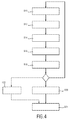
- Fig. 2 shows a schematic block diagram of the ultrasound system 10.
- the ultrasound system 10 comprises an ultrasound probe (PR) 14, the controlling unit (CU) 16, the display (DI) 18 and the input device (ID) 20.
- the probe (PR) 14 comprises a phased two-dimensional transducer array (TR) 26.
- the controlling unit (CU) 16 may comprise a central processing unit (CPU) 28 that may include analog and/or digital electronic circuits, a processor, microprocessor or the like to coordinate the whole image acquisition and provision.
- the central processing unit (CPU) 28 does not need to be a separate entity or unit within the ultrasound system 10. It can be a part of the controlling unit 16 and generally be hardware or software implemented.
- the central processing unit (CPU) 28 as a part of the controlling unit (CU) 16 may control a beam former (BF) 30 and, by this, what images of the volume 40 are taken and how these images are taken.
- the beam former (BF) 30 generates the voltages that drive the transducer array (TR) 26, determines repetition frequencies, it may scan, focus and apodize the transmitted beam and the reception of receive beam(s) and may further amplify filter and digitize the echo voltage stream returned by the transducer array (TR) 26.
- the central processing unit (CPU) 28 of the controlling unit (CU) 16 may determine general scanning strategies.
- Such general strategies may include a desired volume acquisition rate, lateral extent of the volume, an elevation extent of the volume, maximum and minimum line densities and scanning line times.
- the beam former (BF) 30 further receives the ultrasound signals from the transducer array (TR) 26 and forwards them as image signals.
- the ultrasound system 10 comprises a signal processor (SP) 32 that receives the image signals.
- the signal processor (SP) 32 is generally provided for analog-to-digital-converting, digital filtering, for example, bandpass filtering, as well as the detection and compression, for example a dynamic range reduction, of the received ultrasound echoes or image signals.
- the signal processor 32 forwards image data.
- the ultrasound system 10 comprises an image processor (IP) 34 that converts image data received from the signal processor 32 into display data.
- IP image processor
- the image processor 34 receives the image data, preprocesses the image data and may store it in a memory (MEM) 36. This image data is then further post-processed to provide images to the user via the display 18.
- MEM memory
- the image processor 34 may form the three-dimensional images out of a multitude of two-dimensional images.
- the ultrasound system 10 may in the current case further comprise an anatomy detector (AD) 38, a slice generator (SLG) 40 and an evaluation unit (EU) 42. It shall be noted that the latter mentioned components may either be realized as separate entities, but may also be included in the image processor 34. All these components may be hardware and/or software implemented.
- AD anatomy detector
- SLG slice generator
- EU evaluation unit
- the anatomy detector (AD) 38 identifies the orientation and position of the anatomical object of interest within the acquired 3D volume data.
- the anatomy detector (AD) may thereto be configured to conduct a model-based segmentation of the acquired 3D volume data. This may be done by finding a best match between the at least one set of volume data and a geometrical mesh model of the anatomical object of interest.
- the model-based segmentation may, for example, be conducted in a similar manner as this is described for a model-based segmentation of CT images in Ecabert, O. et al.: "Automatic Model-based Segmentation of the Heart in CT Images", IEEE Transactions on Medical Imaging, Vol. 27(9), p. 1189-1291, 2008 .
- the geometrical mesh model of the anatomical object of interest may comprise respective segments representing respective anatomic features. Accordingly, the anatomy detector 38 may provide an anatomy-related description of the volume data, which identifies respective geometrical locations of respective anatomic features in the volume data.
- Such a model-based segmentation usually starts with the identification of the orientation of the anatomical object of interest (e.g. the heart) within the 3D ultrasonic volume data. This may, for example, be done using a three-dimensional implementation of the Generalized Hough Transform. Pose misalignment may be corrected by matching the geometrical model to the image making use of a global similarity transformation.
- the segmentation comprises an initial model that roughly represents the shape of the anatomical object of interest.
- Said model may be a multi-compartment mesh model. This initial model will be deformed by a transformation.
- This transformation is decomposed into two transformations of different kinds: A global transformation that can translate, rotate or rescale the initial shape of the geometrical model, if needed, and a local deformation that will actually deform the geometrical model so that it matches more precisely to the anatomical object of interest. This is usually done by defining the normal vectors of the surface of the geometrical model to match the image gradient; that is to say, the segmentation will look in the received ultrasonic image for bright-to-dark edges (or dark-to-bright), which usually represent the tissue borders in ultrasound images, i.e. the boundaries of the anatomical object of interest.
- the segmented 3D volume data may then be further post-processed.
- the slice generator (SLG) 40 generates a plurality of two-dimensional slices from the 3D volume data. Landmarks are thereto encoded within the geometrical model that defines the planes of said 2D slices. A set of three or more landmarks can represent a plane. These encoded landmarks may be mapped onto the segmented 3D volume data so as to obtain a set of 2D standard views of the anatomical object of interest generated from the 3D volume data.
- the slice generator 40 may be furthermore configured to define for each 2D standard view which anatomical features of the anatomical object of interest are expected to be contained within said view. This may be done using the geometrical model that is encoded with the anatomic features of the anatomical object of interest. It should thus be known which anatomical features should occur in which 2D standard view.
- the evaluation unit (EU) 42 may then evaluate a quality factor for each of the generated plurality of 2D slices by comparing each of said generated slices with the anatomical features expected for the respective 2D standard view. In other words, the evaluation unit 42 computes the coverage of each of the 2D standard views by the 3D volume data. This may be done by computing the overlap of the structure that should be covered and the field of view of the 3D ultrasound scan.
- the quality factor that is evaluated within the evaluation unit 42 for each of the generated plurality of 2D slices may thus be a quantitative factor that includes a ratio to which extent the expected anatomical features are included in the respective 2D slice. This may be done by comparing the field of view of each of the 2D slices to the geometrical model of the anatomical object.
- This information can be presented as a graphical icon, e.g. as a traffic light, and/or as a percentage on the display 18.
- the generated 2D slices of the anatomical object of interest are preferably illustrated on the display 18 simultaneously, wherein each illustrated 2D slice is illustrated together with a graphical representation of the quality factor (icon and/or percentage) that indicates the quality of the respective 2D slice.
- a single 3D ultrasound scan of the anatomical object of interest there is usually not only performed a single 3D ultrasound scan of the anatomical object of interest.
- a plurality of 3D ultrasound scans of the anatomical object of interest are performed.
- the above-mentioned processing is performed by the ultrasound system 10.
- the plurality of sets of volume data resulting from the different 3D scans and the 2D slices that are generated in the above-mentioned way from said sets of volume data may be stored within the memory (MEM) 36 together with the evaluated quality factors of each of the 2D slices.
- MEM memory
- a selector (SEL) 44 is configured to select for each 2D standard view a 2D slice that has the highest quality factor. This may be done by comparing the evaluated quality factors of corresponding 2D slices that are generated from each of the plurality of 3D sets of volume data which are stored in the memory 36. In other words, the selector 44 selects for each standard view the best 2D slice out of all 2D slices that have been generated from the different sets of 3D volume data (different ultrasound scans). This means that the different 2D standard views that are simultaneously illustrated on the display 18 may result from different 3D ultrasound scans, wherein the selector 44 automatically determines from which 3D volume data set a specific 2D standard view may be generated best.
- TEE transesophageal echocardiography
- Fig. 3a e.g. illustrates the ME four chamber view
- Fig. 3b the ME two chamber view
- Fig. 3c the ME LAX view and so on.
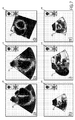
- Fig. 4 shows a schematic block diagram for illustrating the method according to an embodiment of the present invention.
- a set of volume data resulting from a 3D ultrasound scan of a body is received.
- a position and orientation of an anatomical object of interest e.g. the human heart
- a model-based segmentation of the at least one set of volume data may be conducted. As already mentioned above, this is done by finding a best match between the at least one set of volume data and a geometrical model of the human heart.
- said model is used to compute the planes of all 20 TEE standard views.
- step S14 by generating a plurality of 2D slices from the at least one set of 3D volume data.
- the respective slice locations are defined based on the geometrical model of the heart. Due to the segmentation that has been performed in advance (in step S12), these respective slice locations may be mapped onto the 3D volume data, such that it is possible to compute the 2D slices from the 3D volume data set by interpolating the 3D image.
- the plane is given by the center of the mitral valve, the center of the tricuspid valve and the apex.
- step S16 it is defined for each 2D standard view which anatomical features of the heart are expected to be contained in said standard view. This may be done by encoding the geometrical model with an anatomy-related description that identifies segments of the heart within each 2D standard view that correspond to respective anatomic features, for example, the heart chambers, the main vessels, the septa, the heart valves, etc. If the geometrical model is encoded with this anatomy-related information, it is easier in the further procedure to evaluate whether the generated 2D slices cover all information that should be included within the respective 2D standard view.
- step S18 it is then evaluated for each of the generated 2D slices how good the 2D standard view is covered.
- a quality factor is computed for each of the generated 2D slices, wherein said quality factor may be a quantitative factor that includes a ratio to which extent the expected anatomical features are included in the respective 2D slice. This may be done by comparing the field of view of each of the generated 2D slices to the geometrical model of the heart.
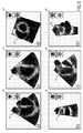
- Fig. 5 shows six 2D slices that have been generated in the above-mentioned way based on a single 3D TEE image (herein referred to as a single set of volume data). The results of the performed segmentation are therein illustrated by border lines 46.
- Fig. 5a shows the 2D slice that corresponds to the ME four chamber standard view (compare to Fig. 3a ).
- Fig. 5B therein shows the 2D slice that corresponds to the ME two chamber standard view (compare to Fig. 3b).
- Fig. 3d shows the generated 2D slice that corresponds to the TE mid SAX standard view (compare to Fig. 3d ).
- Fig. 5h shows the generated 2D slice that corresponds to the ME AV SAX standard view (compare to Fig.
- Fig. 5i shows the generated 2D slice that corresponds to the ME AV LAX standard view (compare to Fig. 3i ).
- Fig. 5m shows the generated 2D slice that corresponds to the ME RV inflow-outflow standard view (compare to Fig. 3m ).
- the generated slices 5h and i are still acceptable, because the main anatomical features of interest, e.g. the aortic valve within Fig. 5h , is still within the field of view.
- the traffic light 48' therefore shows a yellow light for these slices.
- most of the border lines 46 are however out of the field of view, meaning that the anatomical features of interest, i.e. the in and outflow of the right ventricle, are not fully covered.
- the quality of this generated 2D slice is thus evaluated to be rather low, which is indicated in Fig. 5m with a traffic light 48" that shows a red light.
- step S10-S18 the method steps S10-S18 are repeated for every new 3D TEE image.
- 3D TEE image very 3D volume data set
- all 20 2D slices are generated and evaluated that correspond to the 20 different 2D TEE standard views illustrated in Fig. 3 .
- For every 2D slice it is defined, which anatomical features are to be expected therein, i.e. which border lines 46 should occur in these 2D slices (step S16). And for every 2D slice it is evaluated, whether the expected border lines are within the field of view, or to which extend this is the case (step S18).
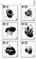
- Fig. 6 illustrates 2D slices that have been generated (and evaluated) based on a second 3D TEE image (second set of volume data) with a different field of view. From Fig. 6 it may be seen that the generated slices 6a, b and d are compared to the slices shown in Fig. 5a, b and d rather unsuitable (indicated by red traffic light 48"). However, the generated 2D slices corresponding to the ME AV SAX standard view ( Fig. 6h ), the ME AV LAX standard view ( Fig. 6i ) and to the ME RV inflow-outflow standard view (see Fig. 6m ) have a rather good quality, since the anatomical features of interest (border lines 46) are this time within the field of view.
- the 2D standard views a, b and d are best covered within the 2D slices that were generated from the first 3D volume data set (illustrated in Fig. 5a, b and d ), while the 2D standard views h, i and m are best covered within the 2D slices that were generated from the second 3D volume data set (illustrated in Fig. 6h, i and m ).
- step S20 the best version for each 2D standard view is then automatically selected. For each 2D standard view one generated 2D slice is selected that has the highest quality factor. This may be done by comparing the evaluated quality factors of corresponding 2D slices generated from each of the received sets of volume data (from each of the received 3D TEE images). This "best selection" is finally illustrated on the display in step S24.
- Fig. 7 The result is shown in Fig. 7 .
- the system 10 automatically selected the more suitable 2D slices that were generated from the first 3D TEE image as 2D standard views a, b and d, while it automatically selected the 2D slices that were generated from the second 3D TEE image as 2D standard views h, i and m.
- the further significant advantage is that the system selects the best 2D slices by itself. The presented method is thus less error-prone and faster compared to the conventional TEE procedure.
- step S22 A still further improvement of the method schematically illustrated in Fig. 4 is shown by step S22.
- the 2D slices may also be generated by performing an additional 2D scan as soon as the system recognizes that a quality factor of a 2D slice that is generated in steps S10-S18 is above a predetermined threshold value. This means that as soon as the system recognizes that the field of view of the taken 3D image is suitable for a specific 2D standard view, the imaging parameters for this 2D standard view from the current location of the transducer probe 14 are computed and the transducer probe 14 automatically performs an additional 2D scan to directly receive the 2D standard view. This "extra" acquisition should however only be done if it has been found in step S18 that the quality of the generated 2D slice is rather high, meaning that the position and orientation of the transducer probe 14 is suitable for acquiring the respective 2D standard view.
- step S22 is not a mandatory, but an optional method step.
- generating the 2D slices from the 3D volume data set and generating the 2D slices directly by performing an additional 2D scan is possible as well.
- a computer program may be stored/distributed on a suitable medium, such as an optical storage medium or a solid-state medium supplied together with or as part of other hardware, but may also be distributed in other forms, such as via the Internet or other wired or wireless telecommunication systems.
- a suitable medium such as an optical storage medium or a solid-state medium supplied together with or as part of other hardware, but may also be distributed in other forms, such as via the Internet or other wired or wireless telecommunication systems.
Landscapes
- Engineering & Computer Science (AREA)
- Health & Medical Sciences (AREA)
- Life Sciences & Earth Sciences (AREA)
- Physics & Mathematics (AREA)
- Theoretical Computer Science (AREA)
- General Health & Medical Sciences (AREA)
- Medical Informatics (AREA)
- Radiology & Medical Imaging (AREA)
- Nuclear Medicine, Radiotherapy & Molecular Imaging (AREA)
- General Physics & Mathematics (AREA)
- Public Health (AREA)
- Molecular Biology (AREA)
- Veterinary Medicine (AREA)
- Animal Behavior & Ethology (AREA)
- Surgery (AREA)
- Heart & Thoracic Surgery (AREA)
- Biomedical Technology (AREA)
- Pathology (AREA)
- Biophysics (AREA)
- Computer Vision & Pattern Recognition (AREA)
- Remote Sensing (AREA)
- Radar, Positioning & Navigation (AREA)
- Data Mining & Analysis (AREA)
- Acoustics & Sound (AREA)
- General Engineering & Computer Science (AREA)
- Vascular Medicine (AREA)
- Databases & Information Systems (AREA)
- Software Systems (AREA)
- Geometry (AREA)
- Cardiology (AREA)
- Computer Networks & Wireless Communication (AREA)
- Quality & Reliability (AREA)
- Computer Graphics (AREA)
- Multimedia (AREA)
- Evolutionary Biology (AREA)
- Artificial Intelligence (AREA)
- Bioinformatics & Cheminformatics (AREA)
- Bioinformatics & Computational Biology (AREA)
- Evolutionary Computation (AREA)
- Ultra Sonic Daignosis Equipment (AREA)
Applications Claiming Priority (2)
| Application Number | Priority Date | Filing Date | Title |
|---|---|---|---|
| US201361807885P | 2013-04-03 | 2013-04-03 | |
| PCT/IB2014/060004 WO2014162232A1 (en) | 2013-04-03 | 2014-03-20 | 3d ultrasound imaging system |
Publications (2)
| Publication Number | Publication Date |
|---|---|
| EP2994053A1 EP2994053A1 (en) | 2016-03-16 |
| EP2994053B1 true EP2994053B1 (en) | 2016-09-28 |
Family
ID=50440725
Family Applications (1)
| Application Number | Title | Priority Date | Filing Date |
|---|---|---|---|
| EP14715698.8A Active EP2994053B1 (en) | 2013-04-03 | 2014-03-20 | 3d ultrasound imaging system |
Country Status (7)
| Country | Link |
|---|---|
| US (3) | US10709425B2 (ja) |
| EP (1) | EP2994053B1 (ja) |
| JP (1) | JP6396420B2 (ja) |
| CN (1) | CN105263420B (ja) |
| BR (1) | BR112015025074B1 (ja) |
| RU (1) | RU2657855C2 (ja) |
| WO (1) | WO2014162232A1 (ja) |
Families Citing this family (40)
| Publication number | Priority date | Publication date | Assignee | Title |
|---|---|---|---|---|
| KR20150068162A (ko) * | 2013-12-11 | 2015-06-19 | 삼성전자주식회사 | 3차원 초음파 영상 통합 장치 및 방법 |
| EP3108456B1 (en) * | 2014-02-19 | 2020-06-24 | Koninklijke Philips N.V. | Motion adaptive visualization in medical 4d imaging |
| US10835210B2 (en) * | 2015-03-30 | 2020-11-17 | Siemens Medical Solutions Usa, Inc. | Three-dimensional volume of interest in ultrasound imaging |
| US11311270B2 (en) * | 2015-07-02 | 2022-04-26 | Siemens Healthcare Gmbh | Intervolume lesion detection and image preparation |
| EP3118576B1 (en) * | 2015-07-15 | 2018-09-12 | Hand Held Products, Inc. | Mobile dimensioning device with dynamic accuracy compatible with nist standard |
| CN108463174B (zh) * | 2015-12-18 | 2021-06-08 | 皇家飞利浦有限公司 | 用于表征对象的组织的装置和方法 |
| AU2017230722B2 (en) | 2016-03-09 | 2022-08-11 | EchoNous, Inc. | Ultrasound image recognition systems and methods utilizing an artificial intelligence network |
| US10891776B2 (en) * | 2016-04-04 | 2021-01-12 | Koninklijke Philips N.V. | Imaging system and method |
| US20190142383A1 (en) * | 2016-05-06 | 2019-05-16 | Koninklijke Philips N.V. | Ultrasonic imaging system with simplified 3d imaging controls |
| EP3471624B1 (en) * | 2016-06-17 | 2022-08-10 | Koninklijke Philips N.V. | System for determining hemodynamic parameters of a patient |
| EP3291175B1 (en) * | 2016-09-05 | 2018-12-12 | RaySearch Laboratories AB | Image processing system and method for interactive contouring of three-dimensional medical data |
| EP3300021B1 (en) * | 2016-09-22 | 2018-12-05 | RaySearch Laboratories AB | Image processing system and method for interactive contouring of three-dimensional medical data |
| EP3533031B1 (en) * | 2016-10-25 | 2023-08-16 | Koninklijke Philips N.V. | A method and apparatus for segmenting a two-dimensional image of an anatomical structure |
| US11452004B2 (en) * | 2016-11-08 | 2022-09-20 | Koninklijke Philips N.V. | Method for wireless data transmission range extension |
| CN110073408B (zh) * | 2016-12-12 | 2023-07-14 | 皇家飞利浦有限公司 | 用于分割解剖结构的二维图像的方法和装置 |
| EP3366221A1 (en) * | 2017-02-28 | 2018-08-29 | Koninklijke Philips N.V. | An intelligent ultrasound system |
| EP3381512A1 (en) | 2017-03-30 | 2018-10-03 | Koninklijke Philips N.V. | Determining at least one final two-dimensional image for visualizing an object of interest in a three-dimensional ultrasound volume |
| EP3422048A1 (en) * | 2017-06-26 | 2019-01-02 | Koninklijke Philips N.V. | Ultrasound imaging method and system |
| EP3668408A1 (en) * | 2017-08-17 | 2020-06-24 | Koninklijke Philips N.V. | Ultrasound system with extraction of image planes from volume data using touch interaction with an image |
| US11382601B2 (en) * | 2018-03-01 | 2022-07-12 | Fujifilm Sonosite, Inc. | Method and apparatus for annotating ultrasound examinations |
| EP3549528A1 (en) | 2018-04-05 | 2019-10-09 | Koninklijke Philips N.V. | Ultrasound imaging system and method |
| EP3569154A1 (en) * | 2018-05-15 | 2019-11-20 | Koninklijke Philips N.V. | Ultrasound processing unit and method, and imaging system |
| KR20210011005A (ko) * | 2018-05-15 | 2021-01-29 | 뉴욕 유니버시티 | 초음파 영상 촬영을 안내하기 위한 시스템 및 방법 |
| JP2021526886A (ja) * | 2018-06-08 | 2021-10-11 | コーニンクレッカ フィリップス エヌ ヴェKoninklijke Philips N.V. | インタラクティブツールを用いてスキャンプロトコルを作成し、及び/又はプロトコルに対する遵守を評価する装置 |
| CN112512434B (zh) * | 2018-08-22 | 2023-08-22 | 深圳迈瑞生物医疗电子股份有限公司 | 一种超声成像的方法及相关设备 |
| US20200178934A1 (en) * | 2018-12-10 | 2020-06-11 | General Electric Company | Ultrasound imaging system and method for displaying a target object quality level |
| CN110604592B (zh) * | 2019-03-04 | 2024-04-02 | 北京大学第三医院 | 一种髋关节的成像方法以及髋关节成像系统 |
| CN110613482A (zh) * | 2019-03-04 | 2019-12-27 | 深圳迈瑞生物医疗电子股份有限公司 | 一种髋关节的成像方法以及髋关节成像系统 |
| CN110613481A (zh) * | 2019-03-04 | 2019-12-27 | 深圳迈瑞生物医疗电子股份有限公司 | 一种髋关节的成像方法以及髋关节成像系统 |
| EP3711673A1 (en) * | 2019-03-18 | 2020-09-23 | Koninklijke Philips N.V. | Methods and systems for adjusting the field of view of an ultrasound probe |
| EP3953863A4 (en) * | 2019-04-10 | 2023-01-11 | The Board of Trustees of the Leland Stanford Junior University | HIGH RESOLUTION 3D IMAGING ALIGNMENT WITH 2D IMAGING |
| CN110604596A (zh) * | 2019-07-30 | 2019-12-24 | 深圳迈瑞生物医疗电子股份有限公司 | 一种髋关节的超声成像方法以及髋关节成像系统 |
| JP7277345B2 (ja) | 2019-11-29 | 2023-05-18 | キヤノンメディカルシステムズ株式会社 | 画像処理装置及び画像処理プログラム |
| KR20210117844A (ko) * | 2020-03-20 | 2021-09-29 | 삼성메디슨 주식회사 | 초음파 영상 장치 및 그 동작 방법 |
| US20220071595A1 (en) * | 2020-09-10 | 2022-03-10 | GE Precision Healthcare LLC | Method and system for adapting user interface elements based on real-time anatomical structure recognition in acquired ultrasound image views |
| CN112381777A (zh) * | 2020-11-09 | 2021-02-19 | 深圳开立生物医疗科技股份有限公司 | 一种图像处理方法、装置及电子设备和存储介质 |
| US20240074738A1 (en) | 2020-12-18 | 2024-03-07 | Koninklijke Philips N.V. | Ultrasound image-based identification of anatomical scan window, probe orientation, and/or patient position |
| US20220317294A1 (en) * | 2021-03-30 | 2022-10-06 | GE Precision Healthcare LLC | System And Method For Anatomically Aligned Multi-Planar Reconstruction Views For Ultrasound Imaging |
| EP4337097A1 (en) * | 2021-05-11 | 2024-03-20 | The Regents Of The University Of California | Wearable ultrasound imaging device for imaging the heart and other internal tissue |
| EP4311499A1 (en) | 2022-07-26 | 2024-01-31 | Koninklijke Philips N.V. | Ultrasound image acquisition |
Family Cites Families (19)
| Publication number | Priority date | Publication date | Assignee | Title |
|---|---|---|---|---|
| US5315512A (en) | 1989-09-01 | 1994-05-24 | Montefiore Medical Center | Apparatus and method for generating image representations of a body utilizing an ultrasonic imaging subsystem and a three-dimensional digitizer subsystem |
| US5207225A (en) * | 1990-11-14 | 1993-05-04 | Advanced Technology Laboratories, Inc. | Transesophageal ultrasonic scanhead |
| US6106466A (en) * | 1997-04-24 | 2000-08-22 | University Of Washington | Automated delineation of heart contours from images using reconstruction-based modeling |
| RU2125836C1 (ru) * | 1997-07-04 | 1999-02-10 | Научно-исследовательский институт точных приборов | Ультразвуковой диагностический комплекс для формирования и визуализации трехмерных изображений |
| JP3802508B2 (ja) * | 2003-04-21 | 2006-07-26 | アロカ株式会社 | 超音波診断装置 |
| US7672491B2 (en) * | 2004-03-23 | 2010-03-02 | Siemens Medical Solutions Usa, Inc. | Systems and methods providing automated decision support and medical imaging |
| JP4563788B2 (ja) * | 2004-12-15 | 2010-10-13 | アロカ株式会社 | 超音波診断装置 |
| WO2006106335A1 (en) * | 2005-04-06 | 2006-10-12 | Depuy International Ltd | Registration system and method |
| CN101331525B (zh) | 2005-12-14 | 2013-03-27 | 皇家飞利浦电子股份有限公司 | 用于使医学3d数据图像观察平面彼此相关联的方法和设备 |
| JP4843357B2 (ja) * | 2006-04-19 | 2011-12-21 | 株式会社東芝 | 画像処理装置 |
| WO2009081318A1 (en) * | 2007-12-18 | 2009-07-02 | Koninklijke Philips Electronics, N.V. | System for multimodality fusion of imaging data based on statistical models of anatomy |
| JP2012506283A (ja) | 2008-10-22 | 2012-03-15 | コーニンクレッカ フィリップス エレクトロニクス エヌ ヴィ | 3次元超音波画像化 |
| US8317705B2 (en) * | 2008-12-10 | 2012-11-27 | Tomtec Imaging Systems Gmbh | Method for generating a motion-corrected 3D image of a cyclically moving object |
| US8265363B2 (en) | 2009-02-04 | 2012-09-11 | General Electric Company | Method and apparatus for automatically identifying image views in a 3D dataset |
| US20120031644A1 (en) * | 2010-04-15 | 2012-02-09 | Los Alamos National Security, Llc | Ultraconducting articles |
| US20120065510A1 (en) * | 2010-09-09 | 2012-03-15 | General Electric Company | Ultrasound system and method for calculating quality-of-fit |
| CN102639063B (zh) * | 2010-09-30 | 2015-03-18 | 柯尼卡美能达株式会社 | 超声波诊断装置 |
| EP2656790A4 (en) * | 2010-12-24 | 2017-07-05 | Konica Minolta, Inc. | Ultrasound image-generating apparatus and image-generating method |
| KR101805619B1 (ko) * | 2011-01-25 | 2017-12-07 | 삼성전자주식회사 | 3차원 의료 영상으로부터 최적의 2차원 의료 영상을 자동으로 생성하는 방법 및 장치 |
-
2014
- 2014-03-20 WO PCT/IB2014/060004 patent/WO2014162232A1/en active Application Filing
- 2014-03-20 JP JP2016505904A patent/JP6396420B2/ja active Active
- 2014-03-20 RU RU2015147174A patent/RU2657855C2/ru active
- 2014-03-20 EP EP14715698.8A patent/EP2994053B1/en active Active
- 2014-03-20 CN CN201480031020.3A patent/CN105263420B/zh active Active
- 2014-03-20 BR BR112015025074-2A patent/BR112015025074B1/pt active IP Right Grant
- 2014-03-20 US US14/781,059 patent/US10709425B2/en active Active
-
2020
- 2020-06-05 US US16/894,398 patent/US20200297321A1/en not_active Abandoned
-
2022
- 2022-11-08 US US17/982,709 patent/US11986355B2/en active Active
Also Published As
| Publication number | Publication date |
|---|---|
| US20200297321A1 (en) | 2020-09-24 |
| WO2014162232A1 (en) | 2014-10-09 |
| US10709425B2 (en) | 2020-07-14 |
| US20160038121A1 (en) | 2016-02-11 |
| EP2994053A1 (en) | 2016-03-16 |
| RU2015147174A (ru) | 2017-05-05 |
| US20230068399A1 (en) | 2023-03-02 |
| JP2016514564A (ja) | 2016-05-23 |
| CN105263420B (zh) | 2018-01-05 |
| JP6396420B2 (ja) | 2018-09-26 |
| BR112015025074A2 (pt) | 2017-07-18 |
| US11986355B2 (en) | 2024-05-21 |
| BR112015025074B1 (pt) | 2022-03-22 |
| RU2657855C2 (ru) | 2018-06-15 |
| CN105263420A (zh) | 2016-01-20 |
Similar Documents
| Publication | Publication Date | Title |
|---|---|---|
| US11986355B2 (en) | 3D ultrasound imaging system | |
| CN106037797B (zh) | 超声成像中感兴趣的三维容积 | |
| US8805047B2 (en) | Systems and methods for adaptive volume imaging | |
| RU2667617C2 (ru) | Система и способ эластографических измерений | |
| CN109310399B (zh) | 医学超声图像处理设备 | |
| US20180008232A1 (en) | Ultrasonic diagnostic apparatus, scan support method, and medical image processing apparatus | |
| EP3742973B1 (en) | Device and method for obtaining anatomical measurements from an ultrasound image | |
| US9877698B2 (en) | Ultrasonic diagnosis apparatus and ultrasonic image processing apparatus | |
| CN111971688A (zh) | 具有用于检索复发患者的成像参数设置的人工神经网络的超声系统 | |
| US11607200B2 (en) | Methods and system for camera-aided ultrasound scan setup and control | |
| US10398411B2 (en) | Automatic alignment of ultrasound volumes | |
| US20130150718A1 (en) | Ultrasound imaging system and method for imaging an endometrium | |
| CN115426954A (zh) | 用于生成路线图图像的双平面和三维超声图像采集以及相关联的系统和设备 | |
| CN112867444B (zh) | 用于引导对超声图像的采集的系统和方法 | |
| US11717268B2 (en) | Ultrasound imaging system and method for compounding 3D images via stitching based on point distances | |
| JP7427002B2 (ja) | フレームのインデックス付け及び画像レビューのためのシステム及び方法 | |
| CN113573645B (zh) | 用于调整超声探头的视场的方法和系统 |
Legal Events
| Date | Code | Title | Description |
|---|---|---|---|
| PUAI | Public reference made under article 153(3) epc to a published international application that has entered the european phase |
Free format text: ORIGINAL CODE: 0009012 |
|
| 17P | Request for examination filed |
Effective date: 20151104 |
|
| AK | Designated contracting states |
Kind code of ref document: A1 Designated state(s): AL AT BE BG CH CY CZ DE DK EE ES FI FR GB GR HR HU IE IS IT LI LT LU LV MC MK MT NL NO PL PT RO RS SE SI SK SM TR |
|
| AX | Request for extension of the european patent |
Extension state: BA ME |
|
| RIC1 | Information provided on ipc code assigned before grant |
Ipc: A61B 8/12 20060101ALN20160301BHEP Ipc: A61B 8/00 20060101ALI20160301BHEP Ipc: G01S 15/89 20060101ALI20160301BHEP Ipc: A61B 8/14 20060101ALI20160301BHEP Ipc: G06T 7/00 20060101ALI20160301BHEP Ipc: A61B 8/08 20060101AFI20160301BHEP |
|
| GRAP | Despatch of communication of intention to grant a patent |
Free format text: ORIGINAL CODE: EPIDOSNIGR1 |
|
| DAX | Request for extension of the european patent (deleted) | ||
| INTG | Intention to grant announced |
Effective date: 20160425 |
|
| GRAS | Grant fee paid |
Free format text: ORIGINAL CODE: EPIDOSNIGR3 |
|
| GRAA | (expected) grant |
Free format text: ORIGINAL CODE: 0009210 |
|
| AK | Designated contracting states |
Kind code of ref document: B1 Designated state(s): AL AT BE BG CH CY CZ DE DK EE ES FI FR GB GR HR HU IE IS IT LI LT LU LV MC MK MT NL NO PL PT RO RS SE SI SK SM TR |
|
| REG | Reference to a national code |
Ref country code: GB Ref legal event code: FG4D |
|
| REG | Reference to a national code |
Ref country code: CH Ref legal event code: EP |
|
| REG | Reference to a national code |
Ref country code: AT Ref legal event code: REF Ref document number: 832058 Country of ref document: AT Kind code of ref document: T Effective date: 20161015 |
|
| REG | Reference to a national code |
Ref country code: IE Ref legal event code: FG4D |
|
| REG | Reference to a national code |
Ref country code: DE Ref legal event code: R096 Ref document number: 602014003996 Country of ref document: DE |
|
| REG | Reference to a national code |
Ref country code: LT Ref legal event code: MG4D |
|
| PG25 | Lapsed in a contracting state [announced via postgrant information from national office to epo] |
Ref country code: NO Free format text: LAPSE BECAUSE OF FAILURE TO SUBMIT A TRANSLATION OF THE DESCRIPTION OR TO PAY THE FEE WITHIN THE PRESCRIBED TIME-LIMIT Effective date: 20161228 Ref country code: RS Free format text: LAPSE BECAUSE OF FAILURE TO SUBMIT A TRANSLATION OF THE DESCRIPTION OR TO PAY THE FEE WITHIN THE PRESCRIBED TIME-LIMIT Effective date: 20160928 Ref country code: LT Free format text: LAPSE BECAUSE OF FAILURE TO SUBMIT A TRANSLATION OF THE DESCRIPTION OR TO PAY THE FEE WITHIN THE PRESCRIBED TIME-LIMIT Effective date: 20160928 Ref country code: HR Free format text: LAPSE BECAUSE OF FAILURE TO SUBMIT A TRANSLATION OF THE DESCRIPTION OR TO PAY THE FEE WITHIN THE PRESCRIBED TIME-LIMIT Effective date: 20160928 Ref country code: FI Free format text: LAPSE BECAUSE OF FAILURE TO SUBMIT A TRANSLATION OF THE DESCRIPTION OR TO PAY THE FEE WITHIN THE PRESCRIBED TIME-LIMIT Effective date: 20160928 |
|
| REG | Reference to a national code |
Ref country code: NL Ref legal event code: MP Effective date: 20160928 |
|
| REG | Reference to a national code |
Ref country code: AT Ref legal event code: MK05 Ref document number: 832058 Country of ref document: AT Kind code of ref document: T Effective date: 20160928 |
|
| PG25 | Lapsed in a contracting state [announced via postgrant information from national office to epo] |
Ref country code: GR Free format text: LAPSE BECAUSE OF FAILURE TO SUBMIT A TRANSLATION OF THE DESCRIPTION OR TO PAY THE FEE WITHIN THE PRESCRIBED TIME-LIMIT Effective date: 20161229 Ref country code: LV Free format text: LAPSE BECAUSE OF FAILURE TO SUBMIT A TRANSLATION OF THE DESCRIPTION OR TO PAY THE FEE WITHIN THE PRESCRIBED TIME-LIMIT Effective date: 20160928 Ref country code: NL Free format text: LAPSE BECAUSE OF FAILURE TO SUBMIT A TRANSLATION OF THE DESCRIPTION OR TO PAY THE FEE WITHIN THE PRESCRIBED TIME-LIMIT Effective date: 20160928 Ref country code: SE Free format text: LAPSE BECAUSE OF FAILURE TO SUBMIT A TRANSLATION OF THE DESCRIPTION OR TO PAY THE FEE WITHIN THE PRESCRIBED TIME-LIMIT Effective date: 20160928 |
|
| REG | Reference to a national code |
Ref country code: FR Ref legal event code: PLFP Year of fee payment: 4 |
|
| PG25 | Lapsed in a contracting state [announced via postgrant information from national office to epo] |
Ref country code: RO Free format text: LAPSE BECAUSE OF FAILURE TO SUBMIT A TRANSLATION OF THE DESCRIPTION OR TO PAY THE FEE WITHIN THE PRESCRIBED TIME-LIMIT Effective date: 20160928 Ref country code: EE Free format text: LAPSE BECAUSE OF FAILURE TO SUBMIT A TRANSLATION OF THE DESCRIPTION OR TO PAY THE FEE WITHIN THE PRESCRIBED TIME-LIMIT Effective date: 20160928 |
|
| PG25 | Lapsed in a contracting state [announced via postgrant information from national office to epo] |
Ref country code: ES Free format text: LAPSE BECAUSE OF FAILURE TO SUBMIT A TRANSLATION OF THE DESCRIPTION OR TO PAY THE FEE WITHIN THE PRESCRIBED TIME-LIMIT Effective date: 20160928 Ref country code: AT Free format text: LAPSE BECAUSE OF FAILURE TO SUBMIT A TRANSLATION OF THE DESCRIPTION OR TO PAY THE FEE WITHIN THE PRESCRIBED TIME-LIMIT Effective date: 20160928 Ref country code: SM Free format text: LAPSE BECAUSE OF FAILURE TO SUBMIT A TRANSLATION OF THE DESCRIPTION OR TO PAY THE FEE WITHIN THE PRESCRIBED TIME-LIMIT Effective date: 20160928 Ref country code: PT Free format text: LAPSE BECAUSE OF FAILURE TO SUBMIT A TRANSLATION OF THE DESCRIPTION OR TO PAY THE FEE WITHIN THE PRESCRIBED TIME-LIMIT Effective date: 20170130 Ref country code: PL Free format text: LAPSE BECAUSE OF FAILURE TO SUBMIT A TRANSLATION OF THE DESCRIPTION OR TO PAY THE FEE WITHIN THE PRESCRIBED TIME-LIMIT Effective date: 20160928 Ref country code: SK Free format text: LAPSE BECAUSE OF FAILURE TO SUBMIT A TRANSLATION OF THE DESCRIPTION OR TO PAY THE FEE WITHIN THE PRESCRIBED TIME-LIMIT Effective date: 20160928 Ref country code: BG Free format text: LAPSE BECAUSE OF FAILURE TO SUBMIT A TRANSLATION OF THE DESCRIPTION OR TO PAY THE FEE WITHIN THE PRESCRIBED TIME-LIMIT Effective date: 20161228 Ref country code: IS Free format text: LAPSE BECAUSE OF FAILURE TO SUBMIT A TRANSLATION OF THE DESCRIPTION OR TO PAY THE FEE WITHIN THE PRESCRIBED TIME-LIMIT Effective date: 20170128 Ref country code: BE Free format text: LAPSE BECAUSE OF FAILURE TO SUBMIT A TRANSLATION OF THE DESCRIPTION OR TO PAY THE FEE WITHIN THE PRESCRIBED TIME-LIMIT Effective date: 20160928 Ref country code: CZ Free format text: LAPSE BECAUSE OF FAILURE TO SUBMIT A TRANSLATION OF THE DESCRIPTION OR TO PAY THE FEE WITHIN THE PRESCRIBED TIME-LIMIT Effective date: 20160928 |
|
| REG | Reference to a national code |
Ref country code: DE Ref legal event code: R097 Ref document number: 602014003996 Country of ref document: DE |
|
| PG25 | Lapsed in a contracting state [announced via postgrant information from national office to epo] |
Ref country code: DK Free format text: LAPSE BECAUSE OF FAILURE TO SUBMIT A TRANSLATION OF THE DESCRIPTION OR TO PAY THE FEE WITHIN THE PRESCRIBED TIME-LIMIT Effective date: 20160928 |
|
| PLBE | No opposition filed within time limit |
Free format text: ORIGINAL CODE: 0009261 |
|
| STAA | Information on the status of an ep patent application or granted ep patent |
Free format text: STATUS: NO OPPOSITION FILED WITHIN TIME LIMIT |
|
| 26N | No opposition filed |
Effective date: 20170629 |
|
| REG | Reference to a national code |
Ref country code: CH Ref legal event code: PL |
|
| PG25 | Lapsed in a contracting state [announced via postgrant information from national office to epo] |
Ref country code: SI Free format text: LAPSE BECAUSE OF FAILURE TO SUBMIT A TRANSLATION OF THE DESCRIPTION OR TO PAY THE FEE WITHIN THE PRESCRIBED TIME-LIMIT Effective date: 20160928 Ref country code: MC Free format text: LAPSE BECAUSE OF FAILURE TO SUBMIT A TRANSLATION OF THE DESCRIPTION OR TO PAY THE FEE WITHIN THE PRESCRIBED TIME-LIMIT Effective date: 20160928 |
|
| PG25 | Lapsed in a contracting state [announced via postgrant information from national office to epo] |
Ref country code: LU Free format text: LAPSE BECAUSE OF NON-PAYMENT OF DUE FEES Effective date: 20170320 |
|
| PG25 | Lapsed in a contracting state [announced via postgrant information from national office to epo] |
Ref country code: CH Free format text: LAPSE BECAUSE OF NON-PAYMENT OF DUE FEES Effective date: 20170331 Ref country code: LI Free format text: LAPSE BECAUSE OF NON-PAYMENT OF DUE FEES Effective date: 20170331 Ref country code: IE Free format text: LAPSE BECAUSE OF NON-PAYMENT OF DUE FEES Effective date: 20170320 |
|
| REG | Reference to a national code |
Ref country code: FR Ref legal event code: PLFP Year of fee payment: 5 |
|
| REG | Reference to a national code |
Ref country code: DE Ref legal event code: R084 Ref document number: 602014003996 Country of ref document: DE |
|
| PG25 | Lapsed in a contracting state [announced via postgrant information from national office to epo] |
Ref country code: MT Free format text: LAPSE BECAUSE OF NON-PAYMENT OF DUE FEES Effective date: 20170320 |
|
| PG25 | Lapsed in a contracting state [announced via postgrant information from national office to epo] |
Ref country code: AL Free format text: LAPSE BECAUSE OF FAILURE TO SUBMIT A TRANSLATION OF THE DESCRIPTION OR TO PAY THE FEE WITHIN THE PRESCRIBED TIME-LIMIT Effective date: 20160928 |
|
| GBPC | Gb: european patent ceased through non-payment of renewal fee |
Effective date: 20180320 |
|
| PG25 | Lapsed in a contracting state [announced via postgrant information from national office to epo] |
Ref country code: GB Free format text: LAPSE BECAUSE OF NON-PAYMENT OF DUE FEES Effective date: 20180320 |
|
| PG25 | Lapsed in a contracting state [announced via postgrant information from national office to epo] |
Ref country code: HU Free format text: LAPSE BECAUSE OF FAILURE TO SUBMIT A TRANSLATION OF THE DESCRIPTION OR TO PAY THE FEE WITHIN THE PRESCRIBED TIME-LIMIT; INVALID AB INITIO Effective date: 20140320 |
|
| PG25 | Lapsed in a contracting state [announced via postgrant information from national office to epo] |
Ref country code: CY Free format text: LAPSE BECAUSE OF FAILURE TO SUBMIT A TRANSLATION OF THE DESCRIPTION OR TO PAY THE FEE WITHIN THE PRESCRIBED TIME-LIMIT Effective date: 20160928 |
|
| PG25 | Lapsed in a contracting state [announced via postgrant information from national office to epo] |
Ref country code: MK Free format text: LAPSE BECAUSE OF FAILURE TO SUBMIT A TRANSLATION OF THE DESCRIPTION OR TO PAY THE FEE WITHIN THE PRESCRIBED TIME-LIMIT Effective date: 20160928 |
|
| PG25 | Lapsed in a contracting state [announced via postgrant information from national office to epo] |
Ref country code: TR Free format text: LAPSE BECAUSE OF FAILURE TO SUBMIT A TRANSLATION OF THE DESCRIPTION OR TO PAY THE FEE WITHIN THE PRESCRIBED TIME-LIMIT Effective date: 20160928 |
|
| REG | Reference to a national code |
Ref country code: DE Ref legal event code: R082 Ref document number: 602014003996 Country of ref document: DE Representative=s name: MEISSNER BOLTE PATENTANWAELTE RECHTSANWAELTE P, DE Ref country code: DE Ref legal event code: R081 Ref document number: 602014003996 Country of ref document: DE Owner name: PHILIPS GMBH, DE Free format text: FORMER OWNER: PHILIPS GMBH, 20099 HAMBURG, DE |
|
| PGFP | Annual fee paid to national office [announced via postgrant information from national office to epo] |
Ref country code: FR Payment date: 20230323 Year of fee payment: 10 |
|
| PGFP | Annual fee paid to national office [announced via postgrant information from national office to epo] |
Ref country code: IT Payment date: 20230321 Year of fee payment: 10 |
|
| PGFP | Annual fee paid to national office [announced via postgrant information from national office to epo] |
Ref country code: DE Payment date: 20240328 Year of fee payment: 11 |