EP2993789A1 - Efficient analog to digital converter - Google Patents
Efficient analog to digital converter Download PDFInfo
- Publication number
- EP2993789A1 EP2993789A1 EP15180900.1A EP15180900A EP2993789A1 EP 2993789 A1 EP2993789 A1 EP 2993789A1 EP 15180900 A EP15180900 A EP 15180900A EP 2993789 A1 EP2993789 A1 EP 2993789A1
- Authority
- EP
- European Patent Office
- Prior art keywords
- analog
- digital converter
- digital
- converter
- coarse
- Prior art date
- Legal status (The legal status is an assumption and is not a legal conclusion. Google has not performed a legal analysis and makes no representation as to the accuracy of the status listed.)
- Withdrawn
Links
Images

Classifications
-
- H—ELECTRICITY
- H03—ELECTRONIC CIRCUITRY
- H03M—CODING; DECODING; CODE CONVERSION IN GENERAL
- H03M1/00—Analogue/digital conversion; Digital/analogue conversion
- H03M1/12—Analogue/digital converters
- H03M1/14—Conversion in steps with each step involving the same or a different conversion means and delivering more than one bit
-
- H—ELECTRICITY
- H03—ELECTRONIC CIRCUITRY
- H03M—CODING; DECODING; CODE CONVERSION IN GENERAL
- H03M3/00—Conversion of analogue values to or from differential modulation
- H03M3/30—Delta-sigma modulation
- H03M3/458—Analogue/digital converters using delta-sigma modulation as an intermediate step
-
- H—ELECTRICITY
- H03—ELECTRONIC CIRCUITRY
- H03M—CODING; DECODING; CODE CONVERSION IN GENERAL
- H03M1/00—Analogue/digital conversion; Digital/analogue conversion
- H03M1/12—Analogue/digital converters
- H03M1/34—Analogue value compared with reference values
- H03M1/38—Analogue value compared with reference values sequentially only, e.g. successive approximation type
- H03M1/42—Sequential comparisons in series-connected stages with no change in value of analogue signal
-
- H—ELECTRICITY
- H03—ELECTRONIC CIRCUITRY
- H03M—CODING; DECODING; CODE CONVERSION IN GENERAL
- H03M1/00—Analogue/digital conversion; Digital/analogue conversion
- H03M1/06—Continuously compensating for, or preventing, undesired influence of physical parameters
- H03M1/0617—Continuously compensating for, or preventing, undesired influence of physical parameters characterised by the use of methods or means not specific to a particular type of detrimental influence
- H03M1/0634—Continuously compensating for, or preventing, undesired influence of physical parameters characterised by the use of methods or means not specific to a particular type of detrimental influence by averaging out the errors, e.g. using sliding scale
- H03M1/0656—Continuously compensating for, or preventing, undesired influence of physical parameters characterised by the use of methods or means not specific to a particular type of detrimental influence by averaging out the errors, e.g. using sliding scale in the time domain, e.g. using intended jitter as a dither signal
- H03M1/066—Continuously compensating for, or preventing, undesired influence of physical parameters characterised by the use of methods or means not specific to a particular type of detrimental influence by averaging out the errors, e.g. using sliding scale in the time domain, e.g. using intended jitter as a dither signal by continuously permuting the elements used, i.e. dynamic element matching
Definitions
- ADC Analog-to-Digital Converters
- sensors such as temperature sensors, humidity sensors, pressure sensors, microphones, baseband of radio receivers and digital instrumentation tools.
- ADC The energy or the power available for the ADC is limited in several applications, for example in battery-powered systems.
- ADC architectures with the highest energy efficiency are preferred.
- Successive-Approximation ADCs (SAR ADC) exhibit the best energy efficiency but their resolution is typically below 12 bits, thus making them not suitable for applications requiring higher resolution.
- Sigma Delta ADCs are preferred. Even if Sigma Delta ADCs show lower energy efficiency than SAR ADCs, Sigma Delta ADCs can offer higher resolution, typically up to 20 bits or more. Circuit designers choose either SAR ADC or Sigma Delta ADC for a particular application based on the suitability parameters.
- An ADC is defined by its bandwidth that is, the range of frequencies it can measure, and its signal to noise ratio that is, how accurately it can measure a signal relative to the noise it introduces.
- the actual bandwidth of an ADC is characterized primarily by its sampling rate, and to a lesser extent by how it handles errors such as aliasing.
- the dynamic range of an ADC is influenced by many factors, including the resolution (the number of output levels it can quantize a signal to), linearity and accuracy (how well the quantization levels match the true analog signal) and jitter (small timing errors that introduce additional noise).
- One of the main performance parameter of an ADC is its resolution, usually expressed in bits.
- a lower noise can be achieved by increasing the ADC resolution (n) or by decreasing the ADC input range (V min -V max ).
- an analog to digital converter in one embodiment, includes a coarse analog to digital converter coupled to an input analog signal.
- the coarse analog to digital converter is configured to provide an approximate digital representation of the input analog signal.
- the analog to digital converter also includes a fine analog to digital converter coupled to the input analog signal.
- the output of the coarse analog to digital converter is coupled to the fine analog to digital converter.
- the fine analog to digital converter is configured to set input range of the fine analog to digital converter as a function of the output of the coarse analog to digital converter.
- an analog to digital converter in another embodiment, includes an input terminal for receiving an analog input signal, an input reference signal terminal for receiving a digital reference signal that is an approximate digital representation of the analog input signal, a digital to analog converter coupled to the input reference signal terminal and a feedback loop including a quantizer that is couples to the digital to analog converter.
- the output of the digital to analog converter is coupled to the input of the quantizer.
- analog to digital converter may further comprise a dynamic element matching module placed between the output of the quantizer and the input of the digital to analog converter.
- analog to digital converter may further comprise an additional digital to analog converter to generate a reference for the digital to analog converter as a function of the digital reference signal.
- Figure 1 illustrates the input and output voltage ranges 100 of an efficient Analog-to-Digital Converter (eADC).
- eADC Analog-to-Digital Converter
- the eADC architecture combines the principles of two different types of analog to digital converters such as a SAR ADC and a Sigma Delta ADC, in a particular manner, as described in various embodiments herein.
- the two analog to digital converters may be of same type but designed differently in that one is optimized for energy efficiency and another for resolution.
- SAR ADC and Sigma Delta ADC
- SAR ADC Sigma Delta ADC
- a SAR ADC performs a first conversion of the analog input and a Sigma Delta ADC performs a second more accurate conversion by using the result of the SAR conversion.
- the input range 102 of the SAR ADC is equal to the input range of the eADC.
- the output of the SAR ADC is used as a coarse approximation of the analog input signal and this information is used to adjust the input range 104 of a Sigma Delta ADC to include the analog input. Because of this adjustment, the Sigma Delta input range does not need to cover the full input range of the eADC in that the input range of the Sigma Delta ADC can be smaller than the input range of the eADC.
- the input range of the eADC is defined by the SAR ADC 202
- the noise introduced in the analog-to-digital conversion is defined by the Sigma Delta ADC 204.
- the energy required by an analog-to-converter mainly depends on its resolution, i.e., the energy requirements depend on the ratio between the input range and the noise introduced by an analog-to-converter.
- the eADC described herein requires less energy because 1) the Sigma Delta ADC can have a lower resolution than the eADC due to a lower input range being used by the eADC and 2) because of the limited requirements on the coarse ADC, the coarse ADC can be implemented with an efficient architecture (such as a SAR) with negligible energy contribution.
- an efficient architecture such as a SAR
- FIG. 2 illustrates an efficient Analog-to-Digital Converter (eADC) 200.
- eADC Analog-to-Digital Converter
- a coarse ADC 202 with sampling rate f coarse and a fine ADC 204 with sampling rate f fine ⁇ f coarse run in parallel.
- Inputs to the coarse ADC 202 and the fine ADC 204 are coupled to a same input source 210.
- the output 206 of the coarse ADC 202 is also inputted to the fine ADC 204 as a reference signal.
- the output 206 of the coarse ADC provides an approximation of the input signal 210.
- the input range of the fine ADC is adapted to include the approximate position found by the coarse ADC.
- a digital processing block 208 combines the digital output D coarse (composed of N bits) of the coarse ADC 202 with the digital output word D fine (composed of M bits) of the fine ADC to generate the digital output of the whole converter (composed of P ⁇ N + M bits).
- the reference signal 206 is used to adjust the effective input range of the fine ADC 204.
- the references of the fine ADC 204 are chosen as a function of the output D coarse of the coarse ADC 202.
- V max ⁇ f coarse - 1 D coarse ⁇ V min where f coarse ( ⁇ ) is the input-output transfer function of the coarse ADC 202 and f coarse - 1 ⁇ is its inverse. If the input-output transfer function of the coarse ADC f coarse ( ⁇ ) is exactly known, the input range of the fine ADC can be chosen to include the ADC input voltage, i.e., V max ⁇ V in ⁇ V min .
- the accuracy and the noise of the eADC 200 only depends on the accuracy of the Sigma Delta ADC (i.e., the fine ADC 204) and the accuracy of its references. It should be noted that references do not necessarily be voltages. In some embodiments, the term "reference" may indicate any other type of analog reference such as current reference, resistive reference, charge reference or capacitance reference.
- the coarse ADC 202 can be implemented using any ADC architecture, such as a Flash converter, a Sigma Delta converter or a SAR converter
- the fine ADC 204 is implemented as an integrating converter, such as a Sigma Delta converter, a slope converter or a dual-slope converter.
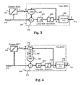
- FIG 3 is a schematic of the eADC 200 illustrating the use of a Sigma Delta ADC as a fine ADC 204.
- the fine ADC 204 includes a digital-to-analog converter (DAC) 302 and a loop filter 304.
- the loop filter 304 is an analog filter (either discrete time or continuous time or in some cases a hybrid of both) which determines the noise shaping behavior of a sigma delta modulator 310.
- the loop filter 304 allows the signal through but suppresses the quantizer's error in the band of interest.
- the fine ADC 204 also includes a quantizer 306.
- the quantizer 306, in one example, is an analog-to-digital converter (1 to N bits) which gets the analog output at the end of the loop filter and converts it to digital form which is a digital representation of the signal at the input.
- a decimation filter 308 is also used.
- the decimation filter 308 is a digital low-pass filter.
- the decimation filter 308 suppresses the high frequency components of the sigma-delta modulator 310 output and generates a 20-bit (for example) code at a lower frequency output rate.
- the DAC 302 is coupled to the reference signal D coarse from the coarse ADC 202.
- the output of the quantizer 306 is inputted into the DAC 302 that in turn provides an output to the subtraction node of the sigma delta modulator 310.
- the output of the feedback DAC 302 is a function of the output of the coarse converter D coarse and the output bitstream of the quantizer 306 b s .
- the DAC 302 references are adjusted as a function of D coarse , as discussed above.
- the value of S can be between 2 to 100.
- the coarse ADC 202 runs at a lower frequency than the frequency of the fine ADC 204.
- the sampling frequency of the fine ADC 204 may be set to equal to the operating frequency of the coarse ADC 202.
- the frequency f coarse can be dynamically set based on the frequency of the analog input signal 210.
- input D coarse may be processed prior to reaching the DAC 302.
- the processing of the signal D coarse may include setting the references of the DAC 302 as a function of the output of the coarse converter.
- the DAC 302 references determine the output range of the DAC 302, and, consequently, the input range of the fine ADC 204.
- the accuracy of the DAC 302 references determines the accuracy of the eADC 200.
- FIG. 4 illustrates a schematic of the eADC 200 with dynamic element matching.
- the eADC 200 may further include a dynamic element matching module (DEM) 312.
- DEM dynamic element matching module
- Dynamic element matching is a digital algorithm that scrambles the unit elements of the DAC 302 on each sample to linearize the DAC transfer function.
- a digital block 314 (OR block) is also used in conjunction with the DEM 312. The digital block 314 combines the bitstream b s and the output of the coarse ADC 202.
- Dynamic Element Matching techniques are described in details in " Dynamic Element Matching Techniques for Data Converters" by Jerry Wyne Bruce II, 1993 .
- the upper and lower references of the DAC 302 are fixed to V P and V N , independent from D coarse .
- ⁇ , ⁇ and D offset are real numbers which depend on the choice of the references of the coarse ADC 202, the references of the fine ADC 204, the number of bits of the coarse ADC 202, the number of bits of the bitstream b s and the amount of over-ranging.
- increasing ⁇ increases the amount of over-ranging and allows larger errors to be introduced by the coarse converter.
- the digital signal D DAC is converted into a thermometer code and randomized by the DEM 312, which drives the DAC 302.
- the signal D DAC can be equal either to D coarse +2 or D coarse -2.
- the analog output levels of the DAC 302 corresponding to those digital values (D coarse ⁇ 2) are the equivalent references of the fine ADC 204 in this example. Because of the DEM operation, any mismatch in the unitary DAC elements are averaged out and those equivalent references are generated very accurately.
- the coarse ADC 202 is a 3-bit ADC, which divides this range into four steps. This results in coarse quantization steps of 0.25V, 0.75V, 1.25V, 1.75V, 2.25V, 2.75V, 3.25V and 3.75V, (for digital code outputs of 0, 1, 2, 3, 4, 5, 6, 7). If the signal is 1.4V, the coarse ADC 202 outputs digital 2.
- the references of the fine ADC 204 will be set to 0.75V for V N and 1.75V as V P . Consequently, the DAC 302 toggles between 0.75V and 1.75V instead of 0V and 4V of a classical 1-bit case. This means that, after the subtraction node 310 (V signal -V dac ) the absolute value of the residual voltage will always smaller than 0.75V (assuming no errors in the coarse converter) which reduces the signal swings of the loop filter 304.
Abstract
Description
- Analog-to-Digital Converters (ADC) are basic building blocks used in several electronic systems to convert analog signals into the digital domain, thus enabling further digital processing on the converted signals. Typical applications include sensors, such as temperature sensors, humidity sensors, pressure sensors, microphones, baseband of radio receivers and digital instrumentation tools.
- The energy or the power available for the ADC is limited in several applications, for example in battery-powered systems. Thus, ADC architectures with the highest energy efficiency are preferred. Successive-Approximation ADCs (SAR ADC) exhibit the best energy efficiency but their resolution is typically below 12 bits, thus making them not suitable for applications requiring higher resolution. If higher resolutions are required, Sigma Delta ADCs are preferred. Even if Sigma Delta ADCs show lower energy efficiency than SAR ADCs, Sigma Delta ADCs can offer higher resolution, typically up to 20 bits or more. Circuit designers choose either SAR ADC or Sigma Delta ADC for a particular application based on the suitability parameters.
- An ADC is defined by its bandwidth that is, the range of frequencies it can measure, and its signal to noise ratio that is, how accurately it can measure a signal relative to the noise it introduces. The actual bandwidth of an ADC is characterized primarily by its sampling rate, and to a lesser extent by how it handles errors such as aliasing. The dynamic range of an ADC is influenced by many factors, including the resolution (the number of output levels it can quantize a signal to), linearity and accuracy (how well the quantization levels match the true analog signal) and jitter (small timing errors that introduce additional noise).
- One of the main performance parameter of an ADC is its resolution, usually expressed in bits. For an ADC with a resolution of n bits and with input range between Vmin and Vmax, i.e., an ADC whose allowed input signal Vin must be Vmin ≤ Vin ≤Vmax, the standard deviation of the noise introduced in the analog-to-digital conversion can be represented by the equation:

- Thus, a lower noise can be achieved by increasing the ADC resolution (n) or by decreasing the ADC input range (Vmin-Vmax).
- This Summary is provided to introduce a selection of concepts in a simplified form that are further described below in the Detailed Description. This Summary is not intended to identify key features or essential features of the claimed subject matter, nor is it intended to be used to limit the scope of the claimed subject matter.
- In one embodiment, an analog to digital converter is disclosed. The analog to digital converter includes a coarse analog to digital converter coupled to an input analog signal. The coarse analog to digital converter is configured to provide an approximate digital representation of the input analog signal. The analog to digital converter also includes a fine analog to digital converter coupled to the input analog signal. The output of the coarse analog to digital converter is coupled to the fine analog to digital converter. The fine analog to digital converter is configured to set input range of the fine analog to digital converter as a function of the output of the coarse analog to digital converter.
- In another embodiment, an analog to digital converter is disclosed. The analog to digital converter includes an input terminal for receiving an analog input signal, an input reference signal terminal for receiving a digital reference signal that is an approximate digital representation of the analog input signal, a digital to analog converter coupled to the input reference signal terminal and a feedback loop including a quantizer that is couples to the digital to analog converter. The output of the digital to analog converter is coupled to the input of the quantizer.
- In embodiments the analog to digital converter may further comprise a dynamic element matching module placed between the output of the quantizer and the input of the digital to analog converter.
- In embodiments the analog to digital converter may further comprise an additional digital to analog converter to generate a reference for the digital to analog converter as a function of the digital reference signal.
- So that the manner in which the above recited features of the present invention can be understood in detail, a more particular description of the invention, briefly summarized above, may be had by reference to embodiments, some of which are illustrated in the appended drawings. It is to be noted, however, that the appended drawings illustrate only typical embodiments of this invention and are therefore not to be considered limiting of its scope, for the invention may admit to other equally effective embodiments. Advantages of the subject matter claimed will become apparent to those skilled in the art upon reading this description in conjunction with the accompanying drawings, in which like reference numerals have been used to designate like elements, and in which:
-
FIG. 1 illustrates operating principles of the efficient Analog-to-Digital Converter (eADC); -
FIG. 2 a schematic of the eADC in accordance with one or more embodiments; -
FIG. 3 is a schematic of the eADC in which a sigma delta ADC is used as a fine ADC in accordance with one or more embodiments; and -
FIG. 4 is a schematic of the eADC with dynamic element matching in accordance with one or more embodiments. -
Figure 1 illustrates the input andoutput voltage ranges 100 of an efficient Analog-to-Digital Converter (eADC). In order to obtain ADC with both high resolution and high power efficiency, the eADC architecture combines the principles of two different types of analog to digital converters such as a SAR ADC and a Sigma Delta ADC, in a particular manner, as described in various embodiments herein. In other embodiments, the two analog to digital converters may be of same type but designed differently in that one is optimized for energy efficiency and another for resolution. The terms "SAR ADC" and "Sigma Delta ADC" are being used herein merely for easy explanation. In the eADC architecture described herein, a SAR ADC performs a first conversion of the analog input and a Sigma Delta ADC performs a second more accurate conversion by using the result of the SAR conversion. Theinput range 102 of the SAR ADC is equal to the input range of the eADC. The output of the SAR ADC is used as a coarse approximation of the analog input signal and this information is used to adjust theinput range 104 of a Sigma Delta ADC to include the analog input. Because of this adjustment, the Sigma Delta input range does not need to cover the full input range of the eADC in that the input range of the Sigma Delta ADC can be smaller than the input range of the eADC. By combining the output of the SAR ADC and the Sigma Delta ADC, an accurate digital representation of the input signal is produced. Since the SAR ADC is only used for adjusting the input range of the Sigma Delta ADC, the accuracy and noise of the converter is determined only by the accuracy and noise of the Sigma Delta ADC. - Thus, the input range of the eADC is defined by the
SAR ADC 202, while the noise introduced in the analog-to-digital conversion is defined by the Sigma Delta ADC 204. A person skilled in the art would appreciate that the energy required by an analog-to-converter mainly depends on its resolution, i.e., the energy requirements depend on the ratio between the input range and the noise introduced by an analog-to-converter. Thus, compared to a standard analog-to-converter with the same resolution, the eADC described herein requires less energy because 1) the Sigma Delta ADC can have a lower resolution than the eADC due to a lower input range being used by the eADC and 2) because of the limited requirements on the coarse ADC, the coarse ADC can be implemented with an efficient architecture (such as a SAR) with negligible energy contribution. -
Figure 2 illustrates an efficient Analog-to-Digital Converter (eADC) 200. As depicted, acoarse ADC 202 with sampling rate f coarse and afine ADC 204 with sampling rate f fine ≥ f coarse run in parallel. Inputs to thecoarse ADC 202 and thefine ADC 204 are coupled to asame input source 210. Theoutput 206 of thecoarse ADC 202 is also inputted to thefine ADC 204 as a reference signal. Theoutput 206 of the coarse ADC provides an approximation of theinput signal 210. The input range of the fine ADC is adapted to include the approximate position found by the coarse ADC. Since the input range of the fine ADC is smaller than the input range of theinput signal 210, thefine ADC 204 can consume less energy than a standard ADC with the same resolution and input range of theADC 200. Adigital processing block 208 combines the digital output Dcoarse (composed of N bits) of thecoarse ADC 202 with the digital output word Dfine (composed of M bits) of the fine ADC to generate the digital output of the whole converter (composed of P ≥ N + M bits). - In one embodiment, the
reference signal 206 is used to adjust the effective input range of thefine ADC 204. For example, if the fine ADC uses references VP and VN, the input range of thefine ADC 204 is between Vmax = αVP and Vmin = βVN, i.e., Vin is in the input range of thefine ADC 204 if Vp ≥ Vmax ≥ Vin ≥ Vn. Thus, to properly adapt its input range, the references of thefine ADC 204 are chosen as a function of the output D coarse of thecoarse ADC 202. In particular, they are chosen so that the following inequality holds:
where f coarse(·) is the input-output transfer function of thecoarse ADC 202 and
- For example, the references of the
fine ADC 204 can be chosen according to the following expressions:

Where Vover-range ,P and Vover-range ,N are positive numbers. Any additional error of the coarse ADC (such as non-linearity or noise) can be tolerated by increasing Vover-range ,P and Vover-range ,N, i.e., by implementing over-ranging. In this way the input range of thefine ADC 204 is enlarged in such a way that the previous inequality is always fulfilled and the input signal always lies inside the input range of thefine ADC 204. Under this condition, the accuracy and the noise of theeADC 200 only depends on the accuracy of the Sigma Delta ADC (i.e., the fine ADC 204) and the accuracy of its references. It should be noted that references do not necessarily be voltages. In some embodiments, the term "reference" may indicate any other type of analog reference such as current reference, resistive reference, charge reference or capacitance reference. - In some examples, while the
coarse ADC 202 can be implemented using any ADC architecture, such as a Flash converter, a Sigma Delta converter or a SAR converter, thefine ADC 204 is implemented as an integrating converter, such as a Sigma Delta converter, a slope converter or a dual-slope converter. These terms and corresponding architectures are well known in the art. Therefore, further description is being omitted so as not to obfuscate the embodiments of the present disclosure as described here. -
Figure 3 is a schematic of theeADC 200 illustrating the use of a Sigma Delta ADC as afine ADC 204. Thefine ADC 204 includes a digital-to-analog converter (DAC) 302 and aloop filter 304. In one embodiment, theloop filter 304 is an analog filter (either discrete time or continuous time or in some cases a hybrid of both) which determines the noise shaping behavior of asigma delta modulator 310. In summary, theloop filter 304 allows the signal through but suppresses the quantizer's error in the band of interest. In this embodiment, thefine ADC 204 also includes aquantizer 306. Thequantizer 306, in one example, is an analog-to-digital converter (1 to N bits) which gets the analog output at the end of the loop filter and converts it to digital form which is a digital representation of the signal at the input. As illustrated, adecimation filter 308 is also used. Thedecimation filter 308 is a digital low-pass filter. In one example, thedecimation filter 308 suppresses the high frequency components of the sigma-delta modulator 310 output and generates a 20-bit (for example) code at a lower frequency output rate. - The
DAC 302 is coupled to the reference signal Dcoarse from thecoarse ADC 202. The output of thequantizer 306 is inputted into theDAC 302 that in turn provides an output to the subtraction node of thesigma delta modulator 310. The output of thefeedback DAC 302 is a function of the output of the coarse converter Dcoarse and the output bitstream of the quantizer 306 bs. In one implementation, theDAC 302 references are adjusted as a function of Dcoarse, as discussed above. In some embodiments, thecoarse ADC 202 runs at a sampling or operating frequency f coarse=f fine/S, where f fine is the sampling or operating frequency of thefine ADC 204 and S is a configurable integer. In some embodiments, the value of S can be between 2 to 100. In other words, in some embodiments, thecoarse ADC 202 runs at a lower frequency than the frequency of thefine ADC 204. However, in other embodiments, the sampling frequency of thefine ADC 204 may be set to equal to the operating frequency of thecoarse ADC 202. In some embodiments, the frequency f coarse can be dynamically set based on the frequency of theanalog input signal 210. - In one embodiment, input Dcoarse may be processed prior to reaching the
DAC 302. The processing of the signal Dcoarse may include setting the references of theDAC 302 as a function of the output of the coarse converter. TheDAC 302 references determine the output range of theDAC 302, and, consequently, the input range of thefine ADC 204. Moreover, the accuracy of theDAC 302 references determines the accuracy of theeADC 200. -
Figure 4 illustrates a schematic of theeADC 200 with dynamic element matching. In the embodiment illustrated infigure 4 , theeADC 200 may further include a dynamic element matching module (DEM) 312. Dynamic element matching is a digital algorithm that scrambles the unit elements of theDAC 302 on each sample to linearize the DAC transfer function. A digital block 314 (OR block) is also used in conjunction with theDEM 312. Thedigital block 314 combines the bitstream bs and the output of thecoarse ADC 202. Dynamic Element Matching techniques are described in details in "Dynamic Element Matching Techniques for Data Converters" by Jerry Wyne Bruce II, 1993. - In one example, the upper and lower references of the
DAC 302 are fixed to VP and VN, independent from Dcoarse. The output of thecoarse ADC 202 and the output bitstream bs are processed by thedigital block 314 that produces the following output:
- Where α, β and Doffset are real numbers which depend on the choice of the references of the
coarse ADC 202, the references of thefine ADC 204, the number of bits of thecoarse ADC 202, the number of bits of the bitstream bs and the amount of over-ranging. In particular, increasing β increases the amount of over-ranging and allows larger errors to be introduced by the coarse converter. The digital signal D DAC is converted into a thermometer code and randomized by theDEM 312, which drives theDAC 302. - In one example, if the references of the
coarse ADC 202 are the same references (VP and VN) of theDAC 302 and the bitstream bs is either 0 or 1, the following parameter values may be used: α = 1,β =4 ,Doffset = -2. The signal DDAC can be equal either to Dcoarse+2 or Dcoarse-2. The analog output levels of theDAC 302 corresponding to those digital values (Dcoarse±2) are the equivalent references of thefine ADC 204 in this example. Because of the DEM operation, any mismatch in the unitary DAC elements are averaged out and those equivalent references are generated very accurately. - In order to understand the zoom-in effect through an example, assume for example that the input range is between 0V and 4V and the
coarse ADC 202 is a 3-bit ADC, which divides this range into four steps. This results in coarse quantization steps of 0.25V, 0.75V, 1.25V, 1.75V, 2.25V, 2.75V, 3.25V and 3.75V, (for digital code outputs of 0, 1, 2, 3, 4, 5, 6, 7). If the signal is 1.4V, thecoarse ADC 202 outputs digital 2. The references of thefine ADC 204 will be set to 0.75V for VN and 1.75V as VP. Consequently, theDAC 302 toggles between 0.75V and 1.75V instead of 0V and 4V of a classical 1-bit case. This means that, after the subtraction node 310 (Vsignal-Vdac) the absolute value of the residual voltage will always smaller than 0.75V (assuming no errors in the coarse converter) which reduces the signal swings of theloop filter 304. - The use of the terms "a" and "an" and "the" and similar referents in the context of describing the subject matter (particularly in the context of the following claims) are to be construed to cover both the singular and the plural, unless otherwise indicated herein or clearly contradicted by context. Recitation of ranges of values herein are merely intended to serve as a shorthand method of referring individually to each separate value falling within the range, unless otherwise indicated herein, and each separate value is incorporated into the specification as if it were individually recited herein. Furthermore, the foregoing description is for the purpose of illustration only, and not for the purpose of limitation, as the scope of protection sought is defined by the claims as set forth hereinafter together with any equivalents thereof entitled to. The use of any and all examples, or exemplary language (e.g., "such as") provided herein, is intended merely to better illustrate the subject matter and does not pose a limitation on the scope of the subject matter unless otherwise claimed. The use of the term "based on" and other like phrases indicating a condition for bringing about a result, both in the claims and in the written description, is not intended to foreclose any other conditions that bring about that result. No language in the specification should be construed as indicating any non-claimed element as essential to the practice of the invention as claimed.
- Preferred embodiments are described herein, including the best mode known to the inventor for carrying out the claimed subject matter. Of course, variations of those preferred embodiments will become apparent to those of ordinary skill in the art upon reading the foregoing description. The inventor expects skilled artisans to employ such variations as appropriate, and the inventor intends for the claimed subject matter to be practiced otherwise than as specifically described herein. Accordingly, this claimed subject matter includes all modifications and equivalents of the subject matter recited in the claims appended hereto as permitted by applicable law. Moreover, any combination of the above-described elements in all possible variations thereof is encompassed unless otherwise indicated herein or otherwise clearly contradicted by context.
Claims (13)
- An analog to digital converter, comprising:a coarse analog to digital converter coupled to an input analog signal, the coarse analog to digital converter configured to provide an approximate digital representation of the input analog signal,a fine analog to digital converter coupled to the input analog signal, wherein the output of the coarse analog to digital converter is coupled to the fine analog to digital converter, wherein the fine analog to digital converter is configured to set input range of the fine analog to digital converter as a function of the output of the coarse analog to digital converter.
- The analog to digital converter of claim 1, wherein the coarse analog to digital converter is of type Successive Approximation Analog to Digital Converter (SAR ADC).
- The analog to digital converter of claim 1, wherein the fine analog to digital converter is of type Sigma Delta Analog to Digital Converter (Sigma Delta ADC).
- The analog to digital converter of claim 1, wherein the input range of the fine analog to digital converter is set by adjusting the references of the fine analog to digital converter.
- The analog to digital converter of claim 1, wherein the fine analog to digital converter is configured to run at a higher sampling frequency than a sampling frequency of the coarse analog to digital converter.
- The analog to digital converter of claim 5, wherein the sampling frequency of the fine analog to digital converter is an integer multiple of the sampling frequency of the coarse analog to digital converter.
- The analog to digital converter of claim 1, wherein a sampling frequency of the fine analog to digital converter is equal to a sampling frequency of the coarse analog to digital converter.
- The analog to digital converter of claim 1, wherein the fine analog to digital converter is a slope Analog to Digital Converter or a dual-slope analog to digital converter.
- The analog to digital converter of claim 1, wherein the fine analog to digital converter includes a quantizer, a loop filter and a digital to analog converter.
- The analog to digital converter of claim 9, wherein in output of the quantizer is coupled to the digital to analog converter and the output of the digital to analog converter is coupled to an input of the quantizer via a loop filter.
- The analog to digital converter of claim 9, wherein the output of the quantizer is coupled to the digital to analog converter via a dynamic element matching module.
- The analog to digital converter of claim 1, wherein a sampling frequency of the coarse analog to digital converter is dynamically set based on a frequency of the input analog signal.
- An analog to digital converter, comprising:an input terminal for receiving an analog input signal;an input reference signal terminal for receiving a digital reference signal that is an approximate digital representation of the analog input signal;a digital to analog converter coupled to the input reference signal terminal; anda feedback loop including a quantizer that is coupled to the digital to analog converter, wherein the output of the digital to analog converter is coupled to the input of the quantizer via a loop filter.
Applications Claiming Priority (1)
| Application Number | Priority Date | Filing Date | Title |
|---|---|---|---|
| US14/475,180 US9325340B2 (en) | 2014-09-02 | 2014-09-02 | Efficient analog to digital converter |
Publications (1)
| Publication Number | Publication Date |
|---|---|
| EP2993789A1 true EP2993789A1 (en) | 2016-03-09 |
Family
ID=53835972
Family Applications (1)
| Application Number | Title | Priority Date | Filing Date |
|---|---|---|---|
| EP15180900.1A Withdrawn EP2993789A1 (en) | 2014-09-02 | 2015-08-13 | Efficient analog to digital converter |
Country Status (3)
| Country | Link |
|---|---|
| US (1) | US9325340B2 (en) |
| EP (1) | EP2993789A1 (en) |
| CN (1) | CN105391450A (en) |
Cited By (2)
| Publication number | Priority date | Publication date | Assignee | Title |
|---|---|---|---|---|
| CN105897273A (en) * | 2016-03-28 | 2016-08-24 | 烟台睿创微纳技术有限公司 | Analog-to-digital conversion circuit and method for main and secondary gradients |
| CN109217872A (en) * | 2018-08-13 | 2019-01-15 | 中国科学院微电子研究所 | Analog-digital converter and D conversion method |
Families Citing this family (19)
| Publication number | Priority date | Publication date | Assignee | Title |
|---|---|---|---|---|
| US9590590B2 (en) * | 2014-11-10 | 2017-03-07 | Analog Devices Global | Delta-sigma modulator having transconductor network for dynamically tuning loop filter coefficients |
| KR101645571B1 (en) * | 2015-08-18 | 2016-08-04 | 연세대학교 산학협력단 | Sigma-Delta Zoom ADC by using Slope ADC with Asynchronous Reference Generation |
| JP6699305B2 (en) * | 2016-04-07 | 2020-05-27 | 株式会社リコー | Signal processing device, photoelectric conversion element, image reading device, image forming device, and signal processing method |
| DE102016112037B4 (en) * | 2016-06-30 | 2022-05-12 | Infineon Technologies Ag | Method and device for analog to digital conversion |
| KR102597604B1 (en) * | 2016-10-19 | 2023-11-10 | 삼성전자주식회사 | Analog Digital Converter and Image Sensor Having The Same |
| US10212500B2 (en) * | 2017-01-27 | 2019-02-19 | Apple Inc. | Digital transducer circuit |
| CN106921392B (en) * | 2017-03-29 | 2018-09-25 | 中国电子科技集团公司第二十四研究所 | Compare the production line analog-digital converter with charge redistribution in advance with input signal |
| US9960785B1 (en) * | 2017-04-06 | 2018-05-01 | Analog Devices Global | Dual-input analog-to-digital converter for improved receiver gain control |
| US10256834B1 (en) * | 2017-09-29 | 2019-04-09 | Taiwan Semiconductor Manufacturing Company, Ltd. | Analog to digital converter |
| KR102441025B1 (en) * | 2017-12-06 | 2022-09-05 | 삼성전자주식회사 | Semiconductor device and operating method thereof |
| CN108459201B (en) * | 2018-03-09 | 2021-01-19 | 中国科学院上海微系统与信息技术研究所 | Mixed sampling system and method for transient signal |
| US10541706B2 (en) * | 2018-05-25 | 2020-01-21 | Arizona Board Of Regents On Behalf Of Arizona State University | Dynamic-zoom analog to digital converter (ADC) having a coarse flash ADC and a fine passive single-bit modulator |
| EP3700092B1 (en) * | 2019-02-25 | 2023-08-30 | ams International AG | Analog-to-digital converter system, electronic device and analog-to-digital conversion method |
| JPWO2020195754A1 (en) * | 2019-03-28 | 2020-10-01 | ||
| JP7417906B2 (en) * | 2019-03-28 | 2024-01-19 | パナソニックIpマネジメント株式会社 | AD converter, sensor processing circuit, and sensor system |
| EP3840228A1 (en) | 2019-12-20 | 2021-06-23 | IMEC vzw | An analog-to-digital converter circuitry, a sensor unit, a neural probe, a micro-electrode array and a method for analog-to-digital conversion |
| US11569826B2 (en) * | 2020-02-16 | 2023-01-31 | Board Of Regents, The University Of Texas System | Time-domain incremental two-step capacitance-to-digital converter |
| US10931299B1 (en) * | 2020-03-31 | 2021-02-23 | Taiwan Semiconductor Manufacturing Company, Ltd. | Analog to digital converter with VCO-based and pipelined quantizers |
| JP2022130998A (en) | 2021-02-26 | 2022-09-07 | セイコーエプソン株式会社 | A/d converter, digital output temperature sensor, circuit arrangement, and oscillator |
Citations (4)
| Publication number | Priority date | Publication date | Assignee | Title |
|---|---|---|---|---|
| US20070024484A1 (en) * | 2005-07-29 | 2007-02-01 | Song Liu | Reference voltage pre-charge in a multi-step sub-ranging analog-to-digital converter |
| US20080143576A1 (en) * | 2006-12-18 | 2008-06-19 | Industrial Technology Research Institute | Analog-to-digital converting system |
| US20100182175A1 (en) * | 2009-01-20 | 2010-07-22 | Kenneth Thet Zin Oo | Current Sensing and Background Calibration to Match Two Resistor Ladders |
| EP2629430A2 (en) * | 2012-02-16 | 2013-08-21 | Stichting voor de Technische Wetenschappen | Two-stage phase digitizer |
Family Cites Families (7)
| Publication number | Priority date | Publication date | Assignee | Title |
|---|---|---|---|---|
| US5006853A (en) * | 1990-02-12 | 1991-04-09 | Texas Instruments Incorporated | Hysteresis insensitive analog to digital converter system using a coarse comparator and a fine comparator |
| US7324036B2 (en) * | 2003-05-12 | 2008-01-29 | Hrl Laboratories, Llc | Adaptive, intelligent transform-based analog to information converter method and system |
| US6999019B2 (en) * | 2004-04-08 | 2006-02-14 | The Boeing Company | Subranging analog-to-digital converter with integrating sample-and-hold |
| US7176819B1 (en) * | 2005-09-08 | 2007-02-13 | Agilent Technologies, Inc. | Precision low noise-delta-sigma ADC with AC feed forward and merged coarse and fine results |
| EP2355358A1 (en) | 2010-02-04 | 2011-08-10 | Nxp B.V. | An ADC, a temperature sensor, a non-contact transponder, and a method of converting analog signals to digital signals |
| CN102270990B (en) * | 2010-06-01 | 2013-09-25 | 北京大学深圳研究生院 | Modulator and designing method thereof |
| CN102832948B (en) * | 2012-09-07 | 2016-03-30 | 复旦大学 | Reconfigurable continuous time type high-speed low-power-consumption sigma-delta modulator |
-
2014
- 2014-09-02 US US14/475,180 patent/US9325340B2/en active Active
-
2015
- 2015-08-13 EP EP15180900.1A patent/EP2993789A1/en not_active Withdrawn
- 2015-09-01 CN CN201510552276.5A patent/CN105391450A/en active Pending
Patent Citations (4)
| Publication number | Priority date | Publication date | Assignee | Title |
|---|---|---|---|---|
| US20070024484A1 (en) * | 2005-07-29 | 2007-02-01 | Song Liu | Reference voltage pre-charge in a multi-step sub-ranging analog-to-digital converter |
| US20080143576A1 (en) * | 2006-12-18 | 2008-06-19 | Industrial Technology Research Institute | Analog-to-digital converting system |
| US20100182175A1 (en) * | 2009-01-20 | 2010-07-22 | Kenneth Thet Zin Oo | Current Sensing and Background Calibration to Match Two Resistor Ladders |
| EP2629430A2 (en) * | 2012-02-16 | 2013-08-21 | Stichting voor de Technische Wetenschappen | Two-stage phase digitizer |
Cited By (3)
| Publication number | Priority date | Publication date | Assignee | Title |
|---|---|---|---|---|
| CN105897273A (en) * | 2016-03-28 | 2016-08-24 | 烟台睿创微纳技术有限公司 | Analog-to-digital conversion circuit and method for main and secondary gradients |
| CN105897273B (en) * | 2016-03-28 | 2019-01-04 | 烟台睿创微纳技术股份有限公司 | A kind of primary and secondary slope analog to digital conversion circuit and method |
| CN109217872A (en) * | 2018-08-13 | 2019-01-15 | 中国科学院微电子研究所 | Analog-digital converter and D conversion method |
Also Published As
| Publication number | Publication date |
|---|---|
| CN105391450A (en) | 2016-03-09 |
| US9325340B2 (en) | 2016-04-26 |
| US20160065231A1 (en) | 2016-03-03 |
Similar Documents
| Publication | Publication Date | Title |
|---|---|---|
| US9325340B2 (en) | Efficient analog to digital converter | |
| CN104980154B (en) | The estimation of digital analog converter static state mistake mismatch error | |
| CN106888018B (en) | Digital measurement of DAC timing mismatch error | |
| CN106888020B (en) | Digital measurement of DAC switch mismatch error | |
| EP2930850B1 (en) | Cancellation of feedback digital-to-analog converter errors in multi-stage delta-sigma analog-to-digital converters | |
| US8803715B2 (en) | Sigma delta modulator including digital to analog coverter (DAC) calibration | |
| US7501965B2 (en) | Correcting for errors that cause generated digital codes to deviate from expected values in an ADC | |
| US10158369B2 (en) | A/D converter | |
| US8212700B2 (en) | Delta-sigma-delta modulator | |
| US7710300B2 (en) | Segmented data shuffler apparatus for a digital to analog converter (DAC) | |
| US9160359B2 (en) | Analog-to-digital converter and analog-to-digital conversion method | |
| US20050280566A1 (en) | Analog-to-digital conversion system, correction circuit, and correction method | |
| US9118340B2 (en) | Analog-to-digital converter and analog-to-digital conversion method | |
| CN106899301B (en) | Protection circuit for adjustable resistance at continuous input ADC | |
| US10404270B2 (en) | Semiconductor device and operating method thereof | |
| EP2811654B1 (en) | Resolution-boosted sigma delta analog-to-digital converter | |
| EP3245740B1 (en) | Efficient dithering technique for sigma-delta analog-to-digital converters | |
| US8102291B2 (en) | Sigma delta modulator and quantizer and quantization method thereof | |
| Wei et al. | Limit Cycle Suppression Technique Using Random Signal In Delta-Sigma DA Modulator | |
| US10873338B1 (en) | Calibration method for precision signal chain linearity | |
| Lin et al. | Analog-to-digital conversion | |
| RU2550591C1 (en) | Integrating voltage analogue-to-digital conversion method | |
| Amanzhol et al. | Analog to digital converter for GNSS signals | |
| Björsell | AD and DA conversion | |
| WO2009019902A1 (en) | Analog/digital conversion cell and analog/digital converter |
Legal Events
| Date | Code | Title | Description |
|---|---|---|---|
| PUAI | Public reference made under article 153(3) epc to a published international application that has entered the european phase |
Free format text: ORIGINAL CODE: 0009012 |
|
| AK | Designated contracting states |
Kind code of ref document: A1 Designated state(s): AL AT BE BG CH CY CZ DE DK EE ES FI FR GB GR HR HU IE IS IT LI LT LU LV MC MK MT NL NO PL PT RO RS SE SI SK SM TR |
|
| AX | Request for extension of the european patent |
Extension state: BA ME |
|
| 17P | Request for examination filed |
Effective date: 20160909 |
|
| RBV | Designated contracting states (corrected) |
Designated state(s): AL AT BE BG CH CY CZ DE DK EE ES FI FR GB GR HR HU IE IS IT LI LT LU LV MC MK MT NL NO PL PT RO RS SE SI SK SM TR |
|
| STAA | Information on the status of an ep patent application or granted ep patent |
Free format text: STATUS: THE APPLICATION IS DEEMED TO BE WITHDRAWN |
|
| 18D | Application deemed to be withdrawn |
Effective date: 20160910 |