EP2993664A2 - Display apparatus, display control method, and display method - Google Patents
Display apparatus, display control method, and display method Download PDFInfo
- Publication number
- EP2993664A2 EP2993664A2 EP15183794.5A EP15183794A EP2993664A2 EP 2993664 A2 EP2993664 A2 EP 2993664A2 EP 15183794 A EP15183794 A EP 15183794A EP 2993664 A2 EP2993664 A2 EP 2993664A2
- Authority
- EP
- European Patent Office
- Prior art keywords
- data
- dyschromatopsia
- correction
- gray scale
- user
- Prior art date
- Legal status (The legal status is an assumption and is not a legal conclusion. Google has not performed a legal analysis and makes no representation as to the accuracy of the status listed.)
- Granted
Links
Images


Classifications
-
- G—PHYSICS
- G09—EDUCATION; CRYPTOGRAPHY; DISPLAY; ADVERTISING; SEALS
- G09G—ARRANGEMENTS OR CIRCUITS FOR CONTROL OF INDICATING DEVICES USING STATIC MEANS TO PRESENT VARIABLE INFORMATION
- G09G3/00—Control arrangements or circuits, of interest only in connection with visual indicators other than cathode-ray tubes
- G09G3/20—Control arrangements or circuits, of interest only in connection with visual indicators other than cathode-ray tubes for presentation of an assembly of a number of characters, e.g. a page, by composing the assembly by combination of individual elements arranged in a matrix no fixed position being assigned to or needed to be assigned to the individual characters or partial characters
- G09G3/34—Control arrangements or circuits, of interest only in connection with visual indicators other than cathode-ray tubes for presentation of an assembly of a number of characters, e.g. a page, by composing the assembly by combination of individual elements arranged in a matrix no fixed position being assigned to or needed to be assigned to the individual characters or partial characters by control of light from an independent source
- G09G3/36—Control arrangements or circuits, of interest only in connection with visual indicators other than cathode-ray tubes for presentation of an assembly of a number of characters, e.g. a page, by composing the assembly by combination of individual elements arranged in a matrix no fixed position being assigned to or needed to be assigned to the individual characters or partial characters by control of light from an independent source using liquid crystals
- G09G3/3607—Control arrangements or circuits, of interest only in connection with visual indicators other than cathode-ray tubes for presentation of an assembly of a number of characters, e.g. a page, by composing the assembly by combination of individual elements arranged in a matrix no fixed position being assigned to or needed to be assigned to the individual characters or partial characters by control of light from an independent source using liquid crystals for displaying colours or for displaying grey scales with a specific pixel layout, e.g. using sub-pixels
-
- G—PHYSICS
- G09—EDUCATION; CRYPTOGRAPHY; DISPLAY; ADVERTISING; SEALS
- G09G—ARRANGEMENTS OR CIRCUITS FOR CONTROL OF INDICATING DEVICES USING STATIC MEANS TO PRESENT VARIABLE INFORMATION
- G09G5/00—Control arrangements or circuits for visual indicators common to cathode-ray tube indicators and other visual indicators
- G09G5/02—Control arrangements or circuits for visual indicators common to cathode-ray tube indicators and other visual indicators characterised by the way in which colour is displayed
-
- G—PHYSICS
- G09—EDUCATION; CRYPTOGRAPHY; DISPLAY; ADVERTISING; SEALS
- G09G—ARRANGEMENTS OR CIRCUITS FOR CONTROL OF INDICATING DEVICES USING STATIC MEANS TO PRESENT VARIABLE INFORMATION
- G09G5/00—Control arrangements or circuits for visual indicators common to cathode-ray tube indicators and other visual indicators
- G09G5/10—Intensity circuits
-
- G—PHYSICS
- G09—EDUCATION; CRYPTOGRAPHY; DISPLAY; ADVERTISING; SEALS
- G09G—ARRANGEMENTS OR CIRCUITS FOR CONTROL OF INDICATING DEVICES USING STATIC MEANS TO PRESENT VARIABLE INFORMATION
- G09G2320/00—Control of display operating conditions
- G09G2320/02—Improving the quality of display appearance
- G09G2320/0242—Compensation of deficiencies in the appearance of colours
-
- G—PHYSICS
- G09—EDUCATION; CRYPTOGRAPHY; DISPLAY; ADVERTISING; SEALS
- G09G—ARRANGEMENTS OR CIRCUITS FOR CONTROL OF INDICATING DEVICES USING STATIC MEANS TO PRESENT VARIABLE INFORMATION
- G09G2320/00—Control of display operating conditions
- G09G2320/06—Adjustment of display parameters
- G09G2320/0613—The adjustment depending on the type of the information to be displayed
-
- G—PHYSICS
- G09—EDUCATION; CRYPTOGRAPHY; DISPLAY; ADVERTISING; SEALS
- G09G—ARRANGEMENTS OR CIRCUITS FOR CONTROL OF INDICATING DEVICES USING STATIC MEANS TO PRESENT VARIABLE INFORMATION
- G09G2320/00—Control of display operating conditions
- G09G2320/06—Adjustment of display parameters
- G09G2320/0626—Adjustment of display parameters for control of overall brightness
-
- G—PHYSICS
- G09—EDUCATION; CRYPTOGRAPHY; DISPLAY; ADVERTISING; SEALS
- G09G—ARRANGEMENTS OR CIRCUITS FOR CONTROL OF INDICATING DEVICES USING STATIC MEANS TO PRESENT VARIABLE INFORMATION
- G09G2320/00—Control of display operating conditions
- G09G2320/06—Adjustment of display parameters
- G09G2320/0666—Adjustment of display parameters for control of colour parameters, e.g. colour temperature
-
- G—PHYSICS
- G09—EDUCATION; CRYPTOGRAPHY; DISPLAY; ADVERTISING; SEALS
- G09G—ARRANGEMENTS OR CIRCUITS FOR CONTROL OF INDICATING DEVICES USING STATIC MEANS TO PRESENT VARIABLE INFORMATION
- G09G2320/00—Control of display operating conditions
- G09G2320/06—Adjustment of display parameters
- G09G2320/0673—Adjustment of display parameters for control of gamma adjustment, e.g. selecting another gamma curve
-
- G—PHYSICS
- G09—EDUCATION; CRYPTOGRAPHY; DISPLAY; ADVERTISING; SEALS
- G09G—ARRANGEMENTS OR CIRCUITS FOR CONTROL OF INDICATING DEVICES USING STATIC MEANS TO PRESENT VARIABLE INFORMATION
- G09G2340/00—Aspects of display data processing
- G09G2340/06—Colour space transformation
-
- G—PHYSICS
- G09—EDUCATION; CRYPTOGRAPHY; DISPLAY; ADVERTISING; SEALS
- G09G—ARRANGEMENTS OR CIRCUITS FOR CONTROL OF INDICATING DEVICES USING STATIC MEANS TO PRESENT VARIABLE INFORMATION
- G09G2354/00—Aspects of interface with display user
Definitions
- One or more exemplary embodiments relate to a display apparatus, a display control apparatus, and a display method, and more particularly to a display apparatus, a display control apparatus, and a display method that use a self-emission device.
- color blindness is the inability to perceive color differences due to inherited deficiencies of cone cells in the retina or acquired damage of the cone cells or vision path deficiencies.
- Trichromats people with normal vision
- Dyschromatopsia refers to a disorder when one of three cone pigments of red, green, and blue is incomplete.
- Achromatopsia refers to a disorder when only two of the three cone pigments are present.
- Protanomaly has a greatly reduced ability of discriminating red and green and perceives a darkening red rather than normal.
- Deuteranomaly has a slightly reduced ability of discriminating red and green but is known to have a same perception level of brightness as that of trichromats.
- Complete achromatopsia refers to a disorder when all cone cells are abnormal and inability to distinguish any colors.
- dyschromatopsia When dyschromatopsia is weak, the ability to discriminate red and green may increase by changing colors perceived by dyschromatopsia individuals. Research into applying such method to a display apparatus that displays an image or a video has continued.
- One or more exemplary embodiments include a display apparatus, a display control apparatus, and a display method capable of displaying an image for dyschromatopsia individuals using a self-emission device without reducing brightness of a display screen.
- a display apparatus includes a data receiving unit for receiving data of an image that is to be displayed; a driving mode determining unit for receiving dyschromatopsia characteristic information of a user and determining a general driving mode or a dyschromatopsia correction driving mode as a driving mode in correspondence to the dyschromatopsia characteristic information of the user; a data converting unit for converting the data in correspondence to the dyschromatopsia characteristic information of the user to generate corrected data; a memory for storing a reference gray scale used in the general driving mode and one or more correction gray scales used in the dyschromatopsia correction driving mode; a data signal output unit for selecting a gray scale corresponding to the dyschromatopsia characteristic information of the user from among the reference gray scale or the one or more correction gray scales and outputting a data signal corresponding to the data or the corrected data based on the selected gray scale; and a light emissive device for receiving the data signal and emitting light of brightness corresponding to the data signal.
- the one or more correction gray scales may have higher brightness values than that of the reference gray scale.
- the data converting unit may store one or more correction matrixes for converting the data and generate the corrected data from the data by using a correction matrix corresponding to the dyschromatopsia characteristic information of the user among the one or more correction matrixes.
- the correction matrix may be an inverse matrix of a Daltonize matrix.
- the dyschromatopsia characteristic information of the user may include information regarding whether the user is a protanomaly user or a deuteranomaly user and a dyschromatopsia degree.
- a display control apparatus includes a data storing unit for storing data of an image to be displayed; a driving mode determining unit for receiving dyschromatopsia characteristic information of a user and determining a general driving mode or a dyschromatopsia correction driving mode as a driving mode in correspondence to the dyschromatopsia characteristic information of the user; a corrected data converting and output unit for generating corrected data by converting the data in correspondence to the dyschromatopsia characteristic information of the user and outputting the corrected data; and a gray scale selection signal output unit for outputting a gray scale selection signal used to select a gray scale corresponding to the dyschromatopsia characteristic information of the user from among a reference gray scale used in the general driving mode and one or more correction gray scales used in the dyschromatopsia correction driving mode.
- the corrected data converting and output unit may store a plurality of correction matrixes for converting the data and generate the corrected data from the data by using a correction matrix corresponding to the dyschromatopsia characteristic information of the user among the plurality of correction matrixes.
- a display apparatus includes the display control apparatus and a display panel for receiving corrected data and a gray scale selection signal from the display control apparatus and displaying an image corresponding to the corrected data according to the gray scale selection signal, wherein the display panel includes a memory for storing a reference gray level scale used in the general driving mode and one or more correction gray scales used in the dyschromatopsia correction driving mode; a data signal output unit for selecting a gray scale corresponding to the dyschromatopsia characteristic information of the user from among the reference gray scale or the one or more correction gray scales and outputting a data signal corresponding to the corrected data based on the selected gray scale; and a light emissive device for receiving the data signal and emitting light of brightness corresponding to the data signal.
- a display apparatus includes a data receiving unit for receiving data of an image that is to be displayed; a correction matrix storing unit for storing a plurality of correction matrixes determined based on an inverse matrix of a Daltonize matrix; a corrected data generating unit for receiving dyschromatopsia characteristic information of a user and converting the data by using a correction matrix in correspondence to the dyschromatopsia characteristic information of the user among the plurality of correction matrixes to generate corrected data; a data signal output unit for outputting a data signal corresponding to the corrected data by using a high brightness mode gray scale; and a light emissive device for receiving the data signal and emitting light of brightness corresponding to the data signal.
- a display method includes receiving data of an image that is to be displayed; receiving dyschromatopsia characteristic information of a user and determining a general driving mode or a dyschromatopsia correction driving mode as a driving mode in correspondence to the dyschromatopsia characteristic information of the user; if the driving mode is determined to be the dyschromatopsia correction driving mode, converting the data in correspondence to the dyschromatopsia characteristic information of the user to generate corrected data; selecting a gray scale corresponding to the dyschromatopsia characteristic information of the user from among a plurality of gray scales including a reference gray scale used in the general driving mode and one or more correction gray scales used in the dyschromatopsia correction driving mode and outputting a data signal corresponding to the data or the corrected data based on the selected gray scale; and displaying a general image or a dyschromatopsia image by using a light emissive device that emits light of brightness corresponding to the data signal.
- the one or more correction gray scales may have higher brightness values than that of the reference gray scale.
- the corrected data may be generated from the data by using a correction matrix corresponding to the dyschromatopsia characteristic information of the user among a plurality of correction matrixes for converting the data.
- the correction matrix may be an inverse matrix of a Daltonize matrix.
- the dyschromatopsia characteristic information of the user may include information regarding whether the user is a protanomaly user or a deuteranomaly user and a dyschromatopsia degree.
- FIG. 1 is a schematic block diagram of a display apparatus 100 according to an exemplary embodiment.
- the display apparatus 100 includes a data receiving unit 110, a driving mode determining unit 120, a data converting unit 130, a data signal output unit 140, a light emissive device 150, and a memory 160.
- the data receiving unit 110 may receive data of an image that is to be displayed.
- the data may include RGB date and the RGB data may be a RGB color coordinate.
- the data receiving unit 110 may receive original data of the image that is to be displayed.
- the driving mode determining unit 120 may receive dyschromatopsia characteristic information of a user and determine a general driving mode or a dyschromatopsia correction driving mode as a driving mode in correspondence to the dyschromatopsia characteristic information of the user.
- Dyschromatopsia individuals may weakly perceive any colors and have a high stimulus threshold value of a color perception, compared to normal individuals.
- Dyschromatopsia is classified into three types: red-green dyschromatopsia, blue-yellow dyschromatopsia, and complete dyschromatopsia. Red-green dyschromatopsia is weak in perceiving red and green and makes it easy to confuse red and green.
- Dyschromatopsia individuals may not exactly determine colors when illumination of a pale face becomes weaker, chroma becomes lower, and size becomes smaller.
- Protanomaly has a greatly reduced ability of discriminating red and green and perceives a dark red rather than normal.
- Deuteranomaly has a slightly reduced ability of discriminating red and green but has a same perception level of brightness as that of normal.
- complete achromatopsia refers to a disorder when all cone cells are abnormal and inability to distinguish any colors.
- the display apparatus 100, a display control apparatus, and a display method according to exemplary embodiments may be provided for dyschromatopsia individuals, and thus, original image data is appropriately converted so that dyschromatopsia individuals may perceive normal colors.
- dyschromatopsia largely includes protanomaly and deuteranomaly will be described by way of example in the present specification.
- the display apparatus 100 may determine driving in the general driving mode or the dyschromatopsia correction driving mode according to the dyschromatopsia characteristic information of the user received by the driving mode determining unit 120.
- the mode when the user is a trichromat (normal) individual, the mode may be determined to be the general driving mode, and when the user is a dyschromatopsia individual, the mode may be determined to be the dyschromatopsia correction driving mode.
- the data converting unit 130 may convert the data in correspondence to the dyschromatopsia characteristic information of the user to generate corrected data.
- the data converting unit 130 may generate corrected RGB data, when the data receiving unit 110 receives RGB data.
- the data converting unit 130 may convert the data received by the data receiving unit 110 by reflecting the dyschromatopsia characteristic information of the user.
- the memory 160 may store a reference gray scale used in the general driving mode and one or more correction gray scales used in the dyschromatopsia correction driving mode.
- the data signal output unit 140 may select a gray scale corresponding to the dyschromatopsia characteristic information of the user from among the reference gray scale or the one or more correction gray scales and output a data signal corresponding to the data or the corrected data based on the selected gray scale.
- the data signal output unit 140 may select the reference gray scale when the user is a trichromat (normal) individual, and select the gray scale corresponding to the dyschromatopsia characteristic information of the user among the one or more correction gray scales when the user is a dyschromatopsia individual.
- the data converting unit 130 may not convert the data or may generate same data as the data received by the data receiving unit 110.
- the data converting unit 130 may store one or more correction matrixes for converting the data and generate the corrected data from the data using a correction matrix corresponding to the dyschromatopsia characteristic information of the user among the one or more correction matrixes.
- the data converting unit 130 may generate the corrected data from the RGB data using an equation below.
- R o G o B o X 255 ⁇ T ⁇ R i G i B i
- X denotes a correction coefficient.
- T denotes a correction matrix.
- R i , G i , and B i denote the RGB data.
- R o , G o , and B o denote the corrected RGB data.
- the correction matrix T may convert the RGB data received by the data receiving unit 110 to emphasize differences between a weakly perceived color and other colors and allow dyschromatopsia individuals to perceive the weakly perceived color and other colors as colors that are perceived by trichromats (normal) individuals.
- the corrected RGB data generated by the data converting unit 130 may have a different value from that of the RGB data and that may exceed 255 gray levels.
- the value exceeds a range that may be displayed by a display apparatus that uses a general 8-bit driving method, and thus it is necessary to reduce the value of the correction RGB data at a predetermined rate.
- Equation 1 X/255 acts to reduce a RGB data value generated by a product of the correction matrix T and the RGB data at a predetermined rate.
- the gray scale may be the correction gray scale.
- the one or more correction gray scales stored in the memory 160 may have different maximum brightness.
- the data signal output unit 140 may select a suitable correction gray scale among the correction gray scales according to the dyschromatopsia characteristic information of the user.
- a dyschromatopsia degree of the first user when among first and second protanomaly users, a dyschromatopsia degree of the first user is greater than that of the second user, brightness of a color displayed to the first user may be greater than that of a color displayed to the second user.
- the light emissive device 150 may receive the data signal and emit light at brightness corresponding to the data signal, thereby displaying an image corresponding to the RGB data or the corrected RGB data.
- FIG. 2 is a table illustrating the correction matrix T according to an exemplary embodiment.
- the data converting unit 130 may provide dyschromatopsia individuals with colors perceived by trichromats using the correction matrix T.
- the correction matrix T may be an inverse matrix of a Daltonize matrix.
- the Daltonize matrix converts the colors perceived by trichromats into colors perceived by dyschromatopsia individuals so that trichromats may indirectly experience colors similar to those seen by dyschromatopsia individuals.
- the correction matrix T shown in FIG. 2 is the inverse matrix of the Daltonize matrix in which a left matrix is applied to protanomaly, and a right matrix is applied to deuteranomaly.
- a leftmost column indicates a dyschromatopsia degree that increases from 0.
- the dyschromatopsia degree of 0 means a trichromat.
- the correction matrix T is used, the data received by the data receiving unit 110 is not changed.
- the dyschromatopsia degree is closer to 1, it may be closer to achromatopsia.
- protanomaly individuals have a lower ability of discriminating red and green than that of trichromats individuals.
- the left matrix applied to protanomaly in the correction matrix T of FIG. 2 changes input RGB data in such a way that protanomaly individuals may easily discriminate red and green.
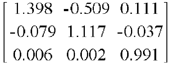
- the following correction matrix T is applied. 1.176 - 0.224 0.048 - 0.036 1.054 - 0.018 0.003 0.001 0.996
- a difference of R and G values is 50.
- a difference of R and G values is 59.94.
- the protanomaly user may easily discriminate red and green on an image displayed through the corrected RGB data.
- the following correction matrix T is applied. 1.176 - 0.224 0.048 - 0.036 1.054 - 0.018 0.003 0.001 0.996
- the corrected RGB data generated by the correction matrix T includes 83.04, 183.96, and 120.
- a difference of R and G values is 80.
- a difference of R and G values is 100.92.
- a color difference of red and green in the corrected RGB data is greater than that of red and green in the RGB data, and thus the protanomaly user may easily discriminate red and green on an image displayed through the corrected RGB data.
- the correction matrix T of FIG. 2 exemplarily illustrates a plurality of matrixes differently applied according to dyschromatopsia degrees.
- the dyschromatopsia degrees may be subdivided more than shown in FIG. 2 .
- protanomaly degrees from 0 to 6 in the correction matrix T of FIG. 2 are expressed in the polynomial.
- a variable r may have a value from 0 to 6 as protanomaly degrees.
- deuteranomaly may be expressed in the following polynomial.
- equation 3 deuteranomaly degrees from 0 to 5 in the correction matrix T of FIG. 2 are expressed in the polynomial.
- a variable g may have a value from 0 to 5 as deuteranomaly degrees.
- the data converting unit 130 may convert the RGB data received by the data receiving unit 110 using the plurality of correction matrix T corresponding to dyschromatopsia degrees, thereby generating correction RGB data.
- the RGB data may be converted by using the polynomials of equations 2 and 3 above, thereby reducing memory consumption necessary for storing the plurality of correction matrix T.
- FIG. 3 is a graph illustrating a brightness characteristic of gray levels of a reference gray scale and a correction gray scale according to an exemplary embodiment.
- a curve A indicates the reference gray scale
- a curve B indicates the correction gray scale.
- a horizontal axis of the graph of FIG. 3 indicates a gray level
- a vertical axis indicates brightness.
- the reference gray scale A and the correction gray scale B present gray levels from 0 to 255, and respectively have 300 nit and 432 nit as brightness at a maximum gray level of 255, i.e. a maximum brightness of each gray level.
- the reference gray scale A may be used in a general driving mode when a user is a trichromat (normal).
- the correction gray scale B may be used in a dyschromatopsia correction driving mode when a user is a dyschromatopsia individual.
- the maximum brightness of the correction gray scale B is 432 nit in FIG. 3 , this is an example for describing the exemplary embodiment.
- the maximum brightness of the correction gray scale B may have a different value according to a dyschromatopsia degree.
- the maximum brightness of the reference gray scale A is 300 nit in FIG. 3 , it may have a different value other than 300 nit as necessary.
- the reference gray scale A is used in the general driving mode and the correction gray scale B is used in the dyschromatopsia correction driving mode.
- the maximum brightness of the correction gray scale B may have a different value according to a dyschromatopsia degree. As described above, the higher the dyschromatopsia degree, the greater value of the maximum brightness of the correction gray scale B has.
- the maximum brightness of the correction gray scale B of FIG. 3 is about 432 nit.
- the correction gray scale B is applied when the dyschromatopsia degree is 0.1.
- the maximum brightness of the correction gray scale B may be obtained by multiplying a dyschromatopsia correction degree value to the maximum brightness of the reference gray scale A.
- the dyschromatopsia correction degree value may be the same as a maximum correction value for an R value.
- the maximum correction value for the R value may be determined as a value having a greatest change rate by comparing input RGB data with its corresponding changed RGB data.
- a difference of R and G values further increases in corrected RGB data generated by converting RGB data by applying the correction matrix T.
- the corrected RGB data may have a value exceeding a displayable maximum gray level of 255.
- the RGB data includes 255, 180, and 100, and a dyschromatopsia degree of the protanomaly user is 0.1
- 264.36, 182.34, and 100.54 are generated as the corrected RGB data
- the difference of R and G values further increases, thereby allowing the protanomaly user to more easily discriminate red and green.
- X in equation 1 above denotes the correction coefficient.
- the correction coefficient X denotes a gray scale having a maximum brightness value of the reference gray scale A in the correction gray scale B and is obtained through the following equation 4.
- X 255 ⁇ L ext L max 1 / ⁇
- L ext denotes the maximum brightness value of the reference gray scale A.
- L max denotes a maximum brightness value of the correction gray scale B.
- corrected RGB data finally generated by the RGB data converting unit 130 is 223.98, 154.49, and 85.19.
- the corrected RGB data (223.98, 154.49, and 85.19) has a smaller value than that of the initially input RGB data (255, 180, and 100). Because of a characteristic of a gray scale that brightness increases as a gray level value increases, if the corrected RGB data (223.98, 154.49, and 85.19) is used, a color may not be displayed at the originally intended brightness, i.e., brightness corresponding to RGB data converted through the correction matrix T.
- the data signal output unit 140 may select a correction gray scale corresponding to a dyschromatopsia degree from the memory 160 to apply the correction gray scale to the corrected RGB data such that the color may be displayed at the originally intended brightness even if the corrected RGB data is used.
- correction gray scale B shown in FIG. 3 is applied to the corrected RGB data, a color that may be perceived by the dyschromatopsia individual may be displayed without deteriorating brightness.
- a display apparatus such as a liquid crystal display apparatus, for adjusting brightness using backlight having an invariable maximum brightness uses a method of reducing brightness of colors except for a color having a weak perception, i.e., a method of emphasizing a color having a relatively weak perception, and thus a display screen is problematically dark overall.
- the display apparatus 100 may flexibly select brightness applied to RGB data converted by a display apparatus that uses a self-emission device such as an organic light-emitting diode (OLED), thereby providing an effect of allowing a dyschromatopsia individual to perceive a color in the same manner as perceived by a trichromat individual without deteriorating brightness.
- a self-emission device such as an organic light-emitting diode (OLED)
- FIG. 4 is a schematic block diagram of a display control apparatus 200 according to an exemplary embodiment.
- the display control apparatus 200 includes a data storing unit 210, a driving mode determining unit 220, a corrected data output unit 230, and a gray scale selection signal output unit 240.
- the data storing unit 210 may store data of an image that is to be displayed.
- the data may comprise RGB data and the RGB data may be a RGB color coordinate.
- the data storing unit 210 may store original data of the image that is to be displayed.
- the driving mode determining unit 220 may receive dyschromatopsia characteristic information of a user and determine a general driving mode or a dyschromatopsia correction driving mode as a driving mode in correspondence to the dyschromatopsia characteristic information of the user.
- the driving mode determining unit 220 may determine the general driving mode when the user is a trichromat (normal) individual and the dyschromatopsia correction driving mode when the user is a dyschromatopsia individual according to the dyschromatopsia characteristic information of the user.
- the corrected data output unit 230 may convert the data in correspondence to the dyschromatopsia characteristic information of the user to generate and output corrected data.
- the gray scale selection signal output unit 240 may output a gray scale selection signal used to select a gray scale corresponding to the dyschromatopsia characteristic information of the user among a reference gray scale used in the general driving mode and one or more correction gray scales used in the dyschromatopsia correction driving mode.
- the display control apparatus 200 may perform a function of controlling a display apparatus provided separately from the display control apparatus 200.
- the display control apparatus 200 may convert the stored data according to the dyschromatopsia characteristic information of the user in the dyschromatopsia correction driving mode for the dyschromatopsia individual, thereby providing an effect of allowing the user to perceive a color in the same manner as perceived by the trichromat (normal) individual.
- the corrected data output unit 230 of the display control apparatus 200 may convert the stored data according to the dyschromatopsia characteristic information of the user to output corrected data.
- the corrected data may be generated through the data and calculation of a correction matrix.
- the correction matrix may be an inverse matrix of a Daltonize matrix as described with reference to FIG. 2 above.
- Different correction matrixes may be used according to the dyschromatopsia characteristic information of the user, i.e. whether the user is a protanomaly user or a deuteranomaly user, and a dyschromatopsia degree.
- the corrected data output unit 230 may store a plurality of correction matrixes for converting the data and generate the corrected data from the Data by using a correction matrix corresponding to the dyschromatopsia characteristic information of the user among the plurality of correction matrixes.
- the corrected data output unit 230 may further include a storage unit for storing the plurality of correction matrixes.
- the gray scale selection signal output by the gray scale selection signal output unit 240 may be a signal that may be recognized by a display apparatus for displaying an image by receiving a signal output from the display control apparatus 200.
- the display apparatus may store the reference gray scale used in the general driving mode and the one or more correction gray scales used in the dyschromatopsia correction driving mode.
- the display apparatus may receive the gray scale selection signal to select the gray scale corresponding to the dyschromatopsia characteristic information of the user among the reference gray scale and the one or more correction gray scales.
- the display apparatus may receive the corrected data from the display control apparatus 200 and display an image corresponding to the corrected data based on the gray scale selected by the gray scale selection signal.
- the display control apparatus 200 may output the corrected data that may be received and recognized by the display apparatus for displaying the image corresponding to the data by using the data, and the gray scale selection signal.
- FIG. 5 is a schematic block diagram of a display apparatus 400 according to another exemplary embodiment.
- the display apparatus 400 includes the display control apparatus 200 described with reference to FIG. 4 above and a display panel 300.
- the display panel 300 may receive corrected data and a gray scale selection signal from the display control apparatus 200 and display an image corresponding to the corrected data according to the gray scale selection signal.
- the display panel 300 includes a memory 310, a data signal output unit 320, and a light emissive device 330.
- the memory 310 may store a reference gray scale used in a general driving mode and one or more correction gray scales used in a dyschromatopsia correction driving mode.
- the display control apparatus 200 may include a driving mode determining unit 220 that receives dyschromatopsia characteristic information of a user and determines a general driving mode or a dyschromatopsia correction driving mode as a driving mode in correspondence to the dyschromatopsia characteristic information of the user.
- a used gray scale may differ according to the determined driving mode.
- the memory 310 may store a reference gray scale or one or more correction gray scales corresponding to the general driving mode or the dyschromatopsia correction driving mode.
- the data signal output unit 320 may output a data signal corresponding to the corrected data based on a gray scale selected from among the reference gray scale or the one or more correction gray scales.
- the light emissive device 330 may receive the data signal and emit light of brightness corresponding to the data signal.
- the display control apparatus 200 may output the corrected data and the gray scale selection signal.
- the display panel 300 may receive the corrected data and the gray scale selection signal.
- the corrected data is converted from data of an image that is to be displayed according to the dyschromatopsia characteristic information of the user, and, as described with reference to FIG. 2 above, may be generated according to a correction matrix corresponding to the dyschromatopsia characteristic information of the user or a polynomial corresponding to the correction matrix.
- the gray scale selection signal is used to select a gray scale corresponding to the dyschromatopsia characteristic information of the user among the reference gray scale or the one or more correction gray scales.
- the corrected data and the gray scale selection signal commonly correspond to the dyschromatopsia characteristic information of the user.
- the corrected data and the gray scale selection signal are generated by the same dyschromatopsia characteristic information, and thus the display panel 300 may output the data signal corresponding to the corrected data based on the gray scale selected by the gray scale selection signal, thereby allowing a dyschromatopsia individual in the dyschromatopsia correction driving mode to perceive a same color as that perceived by a trichromat (normal) individual.
- FIG. 6 is a schematic block diagram of a display apparatus 500 according to another exemplary embodiment.
- the display apparatus 500 includes a data receiving unit 510, a correction matrix storing unit 520, a corrected data generating unit 530, a data signal output unit 540, and a light emissive device 550.
- the data receiving unit 510 may receive data of an image that is to be displayed.
- the data may comprise RGB data and the RGB data may be a RGB color coordinate.
- the RGB data may be the original image data of the image that is to be displayed.
- the correction matrix storing unit 520 may store a plurality of correction matrixes determined based on an inverse matrix of a Daltonize matrix.
- the Daltonize matrix converts a color perceived by a trichromat (normal) individual into a color perceived by a dyschromatopsia individual, and thus, the trichromat individual may indirectly experience a color in a similar way as seen by the dyschromatopsia individual.
- the correction matrixes may be used to generate RGB data converted to allow the dyschromatopsia individual to perceive a similar color to that seen by the trichromat individual.
- the corrected data generating unit 530 may receive dyschromatopsia characteristic information of a user and convert the data by using a correction matrix selected from among the plurality of correction matrixes in correspondence to the dyschromatopsia characteristic information of the user to generate corrected data.
- the dyschromatopsia characteristic information may include information regarding whether the user is a protanomaly user or a deuteranomaly user and a dyschromatopsia degree.
- the corrected data generating unit 530 may select a correction matrix in correspondence to the dyschromatopsia characteristic information and convert the data by the selected correction matrix to generate the corrected data.
- the data signal output unit 540 may output a data signal corresponding to the corrected data by using a high brightness mode gray scale.
- the light emissive device 550 may receive the data signal and emit light of brightness corresponding to the data signal to display an image.
- FIG. 7 is a graph illustrating a high brightness mode gray scale C used by the display apparatus 500 according to another exemplary embodiment.
- the high brightness mode gray scale C used by the display apparatus 500 may display 500 nit maximum within a gray level range from 0 to 255, and may be applied when a dyschromatopsia degree is 0.142.
- the display apparatuses 100 and 400 and the display control apparatus 200 described with reference to FIGS. 1 through 5 above may use a plurality of correction gray scales corresponding to dyschromatopsia characteristic information of a user, whereas the display apparatus 500 may use only the high brightness mode gray scale C.
- the high brightness mode gray scale C as shown in FIG. 7 may be used to a user having the dyschromatopsia degree below 0.142.
- a different gray scale may not be applied according to the dyschromatopsia degree, and thus a data signal corresponding to the correction RGB data may be output by differentiating a gray level range used according to dyschromatopsia degrees in the high brightness mode gray scale C.
- a gray level X in the high brightness mode gray scale C indicates brightness of 300 nit and indicates a maximum brightness of the reference gray scale A used in the display apparatuses 100 and 400 according to exemplary embodiments.
- the display apparatus 500 output the data signal corresponding to the corrected RGB data within a gray level range from 0 to X.
- the gray level X corresponds to brightness of 300 nit in FIG. 7 but is not limited thereto.
- L ext denotes a maximum brightness value according to the dyschromatopsia characteristic information.
- L max denotes a maximum brightness value of the high brightness mode gray scale C.
- the maximum brightness value according to the dyschromatopsia characteristic information is 300 nit, and the maximum brightness value of the high brightness mode gray scale C is 500 nit, and thus the gray level X is about 202.
- the data signal output unit 540 may output a data signal corresponding to the corrected RGB data within a gray level range from 0 to 202.
- the corrected data generating unit 530 may convert RGB data by using the following equation.
- R o G o B o X 255 ⁇ T ⁇ R i G i B i
- X denotes a correction coefficient.
- T denotes an inverse matrix of a Daltonize matrix according to the dyschromatopsia characteristic information.
- R i , G i , and B i denote the RGB data.
- R o , G o , and B o denote the corrected RGB data.
- the inverse matrix of the Daltonize matrix may be a correction matrix stored in the correction matrix storing unit 520 and may be used to convert the RGB data in correspondence to the dyschromatopsia characteristic information of the user.
- the correction coefficient X may be a gray level having a maximum brightness value according to the dyschromatopsia characteristic information in the high brightness mode gray scale C and may have a same value as that of the gray level X calculated using equation 5 above.
- the correction coefficient X is 202
- the correction matrix selected according to the dyschromatopsia characteristic information of the user is a unit matrix, and thus RGB data converted by the correction matrix have a same value as that of the RGB data.
- the corrected RGB data generated by the corrected RGB data generating unit 530 has a value by multiplying (202/255) to the RGB data.
- a maximum gray level that may be displayed by an 8 bit driving display apparatus is 255, and thus a maximum value of the corrected RGB data does not exceed 202.
- the data signal output unit 540 may output a data signal corresponding to the corrected RGB data within a gray level range from 0 to 202.
- the gray level X is about 239.
- the corrected data generating unit 530 may select a matrix corresponding to the dyschromatopsia degree of 0.1 and generate the corrected RGB data according to equation 6 above.
- the data signal output unit 540 may output a data signal corresponding to the corrected RGB data within a gray level range from 0 to 239.
- FIG. 8 is a flowchart illustrating a display method according to an exemplary embodiment.
- the display method may include a data preparing operation (S110), a driving mode determining operation (S120), a corrected data generating operation (S130), a data signal output operation (S140), and an image display operation (S150).
- the data may comprise RGB data.
- the data preparing operation (S110) that is an operation of preparing data of an image that is to be displayed may receive original data for displaying a specific image or convert stored data into a state in which the data may be utilized.
- the driving mode determining operation (S120) may receive dyschromatopsia characteristic information of a user and determine a general driving mode or a dyschromatopsia correction driving mode as a driving mode in correspondence to the dyschromatopsia characteristic information of the user.
- the corrected data generating operation may convert the data in correspondence to the dyschromatopsia characteristic information of the user and generate corrected data.
- the data signal output operation may select one gray scale corresponding to the dyschromatopsia characteristic information of the user from among a plurality of gray scales including a reference gray scale used in the general driving mode and one or more correction gray scales used in the dyschromatopsia correction driving mode, and may output a data signal corresponding to the data or the corrected data based on the selected gray scale.
- the corrected data may be generated from the data by using a correction matrix corresponding to the dyschromatopsia characteristic information of the user.
- the corrected data generating operation (S130) may be omitted, and the data signal corresponding to the data may be output based on the selected gray scale in the data signal output operation (S140).
- the image display operation (S150) may display an image for a general image dyschromatopsia by using a light emissive device that emits light of brightness corresponding to the data signal.
- a general image corresponding to the data and the data signal output based on the reference gray scale may be displayed, and when the dyschromatopsia correction driving mode is determined, a dyschromatopsia image corresponding to the corrected data and the data signal output based on the correction gray scale corresponding to the dyschromatopsia characteristic information of the user may be displayed.
- a display apparatus capable of displaying an image for dyschromatopsia individuals using a self-emission device without reducing brightness of a display screen may be provided.
Landscapes
- Engineering & Computer Science (AREA)
- Physics & Mathematics (AREA)
- Computer Hardware Design (AREA)
- General Physics & Mathematics (AREA)
- Theoretical Computer Science (AREA)
- Chemical & Material Sciences (AREA)
- Crystallography & Structural Chemistry (AREA)
- Control Of Indicators Other Than Cathode Ray Tubes (AREA)
- Controls And Circuits For Display Device (AREA)
- Processing Of Color Television Signals (AREA)
Abstract
Description
- One or more exemplary embodiments relate to a display apparatus, a display control apparatus, and a display method, and more particularly to a display apparatus, a display control apparatus, and a display method that use a self-emission device.
- In general, color blindness is the inability to perceive color differences due to inherited deficiencies of cone cells in the retina or acquired damage of the cone cells or vision path deficiencies. Trichromats (people with normal vision) perceive combinations of the three primary colors (red, green, and blue). Dyschromatopsia refers to a disorder when one of three cone pigments of red, green, and blue is incomplete. Achromatopsia refers to a disorder when only two of the three cone pigments are present.
- Protanomaly has a greatly reduced ability of discriminating red and green and perceives a darkening red rather than normal. Deuteranomaly has a slightly reduced ability of discriminating red and green but is known to have a same perception level of brightness as that of trichromats. Complete achromatopsia refers to a disorder when all cone cells are abnormal and inability to distinguish any colors.
- When dyschromatopsia is weak, the ability to discriminate red and green may increase by changing colors perceived by dyschromatopsia individuals. Research into applying such method to a display apparatus that displays an image or a video has continued.
- One or more exemplary embodiments include a display apparatus, a display control apparatus, and a display method capable of displaying an image for dyschromatopsia individuals using a self-emission device without reducing brightness of a display screen.
- Additional aspects will be set forth in part in the description which follows and, in part, will be apparent from the description, or may be learned by practice of the presented embodiments.
- According to one or more exemplary embodiments, a display apparatus includes a data receiving unit for receiving data of an image that is to be displayed; a driving mode determining unit for receiving dyschromatopsia characteristic information of a user and determining a general driving mode or a dyschromatopsia correction driving mode as a driving mode in correspondence to the dyschromatopsia characteristic information of the user; a data converting unit for converting the data in correspondence to the dyschromatopsia characteristic information of the user to generate corrected data; a memory for storing a reference gray scale used in the general driving mode and one or more correction gray scales used in the dyschromatopsia correction driving mode; a data signal output unit for selecting a gray scale corresponding to the dyschromatopsia characteristic information of the user from among the reference gray scale or the one or more correction gray scales and outputting a data signal corresponding to the data or the corrected data based on the selected gray scale; and a light emissive device for receiving the data signal and emitting light of brightness corresponding to the data signal.
- The one or more correction gray scales may have higher brightness values than that of the reference gray scale. The data converting unit may store one or more correction matrixes for converting the data and generate the corrected data from the data by using a correction matrix corresponding to the dyschromatopsia characteristic information of the user among the one or more correction matrixes.
- The correction matrix may be an inverse matrix of a Daltonize matrix. The data may comprise RGB data and the data converting unit may generate the corrected data from the RGB data by using the following equation:

- The correction coefficient X may be calculated through the following equation:

- The dyschromatopsia characteristic information of the user may include information regarding whether the user is a protanomaly user or a deuteranomaly user and a dyschromatopsia degree.
- According to one or more exemplary embodiments, a display control apparatus includes a data storing unit for storing data of an image to be displayed; a driving mode determining unit for receiving dyschromatopsia characteristic information of a user and determining a general driving mode or a dyschromatopsia correction driving mode as a driving mode in correspondence to the dyschromatopsia characteristic information of the user; a corrected data converting and output unit for generating corrected data by converting the data in correspondence to the dyschromatopsia characteristic information of the user and outputting the corrected data; and a gray scale selection signal output unit for outputting a gray scale selection signal used to select a gray scale corresponding to the dyschromatopsia characteristic information of the user from among a reference gray scale used in the general driving mode and one or more correction gray scales used in the dyschromatopsia correction driving mode.
- The corrected data converting and output unit may store a plurality of correction matrixes for converting the data and generate the corrected data from the data by using a correction matrix corresponding to the dyschromatopsia characteristic information of the user among the plurality of correction matrixes.
- According to one or more exemplary embodiments, a display apparatus includes the display control apparatus and a display panel for receiving corrected data and a gray scale selection signal from the display control apparatus and displaying an image corresponding to the corrected data according to the gray scale selection signal, wherein the display panel includes a memory for storing a reference gray level scale used in the general driving mode and one or more correction gray scales used in the dyschromatopsia correction driving mode; a data signal output unit for selecting a gray scale corresponding to the dyschromatopsia characteristic information of the user from among the reference gray scale or the one or more correction gray scales and outputting a data signal corresponding to the corrected data based on the selected gray scale; and a light emissive device for receiving the data signal and emitting light of brightness corresponding to the data signal.
- According to one or more exemplary embodiments, a display apparatus includes a data receiving unit for receiving data of an image that is to be displayed; a correction matrix storing unit for storing a plurality of correction matrixes determined based on an inverse matrix of a Daltonize matrix; a corrected data generating unit for receiving dyschromatopsia characteristic information of a user and converting the data by using a correction matrix in correspondence to the dyschromatopsia characteristic information of the user among the plurality of correction matrixes to generate corrected data; a data signal output unit for outputting a data signal corresponding to the corrected data by using a high brightness mode gray scale; and a light emissive device for receiving the data signal and emitting light of brightness corresponding to the data signal.
- The data may comprise RGB data and the corrected data generating unit may convert the RGB data by using the following equation:

- The correction coefficient X may be calculated through the following equation:

- According to one or more exemplary embodiments, a display method includes receiving data of an image that is to be displayed; receiving dyschromatopsia characteristic information of a user and determining a general driving mode or a dyschromatopsia correction driving mode as a driving mode in correspondence to the dyschromatopsia characteristic information of the user; if the driving mode is determined to be the dyschromatopsia correction driving mode, converting the data in correspondence to the dyschromatopsia characteristic information of the user to generate corrected data; selecting a gray scale corresponding to the dyschromatopsia characteristic information of the user from among a plurality of gray scales including a reference gray scale used in the general driving mode and one or more correction gray scales used in the dyschromatopsia correction driving mode and outputting a data signal corresponding to the data or the corrected data based on the selected gray scale; and displaying a general image or a dyschromatopsia image by using a light emissive device that emits light of brightness corresponding to the data signal.
- The one or more correction gray scales may have higher brightness values than that of the reference gray scale. The corrected data may be generated from the data by using a correction matrix corresponding to the dyschromatopsia characteristic information of the user among a plurality of correction matrixes for converting the data.
- The data may comprise RGB data and corrected RGB data may be generated from the RGB data by using the following equation:

- The correction coefficient X may be calculated through the following equation:

- The correction matrix may be an inverse matrix of a Daltonize matrix. The dyschromatopsia characteristic information of the user may include information regarding whether the user is a protanomaly user or a deuteranomaly user and a dyschromatopsia degree.
- A more complete appreciation of the invention, and many of the attendant advantages thereof, will be readily apparent as the same becomes better understood by reference to the following detailed description when considered in conjunction with the accompanying drawings, in which like reference symbols indicate the same or similar components, wherein:
-
FIG. 1 is a schematic block diagram of a display apparatus according to an exemplary embodiment; -
FIG. 2 is a table illustrating a correction matrix according to an exemplary embodiment; -
FIG. 3 is a graph illustrating a brightness characteristic of gray levels of a reference gray scale and a correction gray scale according to an exemplary embodiment; -
FIG. 4 is a schematic block diagram of a display control apparatus according to an exemplary embodiment; -
FIG. 5 is a schematic block diagram of a display apparatus according to another exemplary embodiment; -
FIG. 6 is a schematic block diagram of a display apparatus according to another exemplary embodiment; -
FIG. 7 is a graph illustrating a high brightness mode gray scale used by a display apparatus according to another exemplary embodiment; and -
FIG. 8 is a flowchart illustrating a display method according to an exemplary embodiment. - Reference will now be made in detail to exemplary embodiments, examples of which are illustrated in the accompanying drawings, wherein like reference numerals refer to like elements throughout. In this regard, the present exemplary embodiments may have different forms and should not be construed as being limited to the descriptions set forth herein. Accordingly, the exemplary embodiments are merely described below, by referring to the figures, to explain aspects of the present description.
- Hereinafter, embodiments of the inventive concept will be described in detail with reference to the accompanying drawings. In addition, in the present specification and drawings, like reference numerals refer to like elements throughout, and thus, redundant descriptions are omitted.
- It will be understood that when an element, such as a layer, a region, or a substrate, is referred to as being "on", "connected to" or "coupled to" another element, it may be directly on, connected or coupled to the other element or intervening elements may be present. In contrast, when an element is referred to as being "directly on," "directly connected to" or "directly coupled to" another element or layer, there are no intervening elements or layers present. Other words used to describe the relationship between elements or layers should be interpreted in a like fashion (e.g., "between," versus "directly between," "adjacent," versus "directly adjacent," etc.).
- It will be understood that although the terms "first", "second", etc. may be used herein to describe various components, these components should not be limited by these terms. These components are only used to distinguish one component from another. As used herein, the singular forms "a," "an" and "the" are intended to include the plural forms as well, unless the context clearly indicates otherwise. It will be further understood that the terms "comprises" and/or "comprising" used herein specify the presence of stated features or components, but do not preclude the presence or addition of one or more other features or components.
-
FIG. 1 is a schematic block diagram of adisplay apparatus 100 according to an exemplary embodiment. - Referring to
FIG. 1 , thedisplay apparatus 100 according to an exemplary embodiment includes adata receiving unit 110, a drivingmode determining unit 120, adata converting unit 130, a datasignal output unit 140, a lightemissive device 150, and amemory 160. - The
data receiving unit 110 may receive data of an image that is to be displayed. The data may include RGB date and the RGB data may be a RGB color coordinate. - That is, the
data receiving unit 110 may receive original data of the image that is to be displayed. - The driving
mode determining unit 120 may receive dyschromatopsia characteristic information of a user and determine a general driving mode or a dyschromatopsia correction driving mode as a driving mode in correspondence to the dyschromatopsia characteristic information of the user. - Dyschromatopsia individuals may weakly perceive any colors and have a high stimulus threshold value of a color perception, compared to normal individuals. Dyschromatopsia is classified into three types: red-green dyschromatopsia, blue-yellow dyschromatopsia, and complete dyschromatopsia. Red-green dyschromatopsia is weak in perceiving red and green and makes it easy to confuse red and green.
- Dyschromatopsia individuals may not exactly determine colors when illumination of a pale face becomes weaker, chroma becomes lower, and size becomes smaller. Protanomaly has a greatly reduced ability of discriminating red and green and perceives a dark red rather than normal. Deuteranomaly has a slightly reduced ability of discriminating red and green but has a same perception level of brightness as that of normal.
- Meanwhile, complete achromatopsia refers to a disorder when all cone cells are abnormal and inability to distinguish any colors.
- The
display apparatus 100, a display control apparatus, and a display method according to exemplary embodiments may be provided for dyschromatopsia individuals, and thus, original image data is appropriately converted so that dyschromatopsia individuals may perceive normal colors. - In particular, a case where dyschromatopsia largely includes protanomaly and deuteranomaly will be described by way of example in the present specification.
- The
display apparatus 100 may determine driving in the general driving mode or the dyschromatopsia correction driving mode according to the dyschromatopsia characteristic information of the user received by the drivingmode determining unit 120. - That is, when the user is a trichromat (normal) individual, the mode may be determined to be the general driving mode, and when the user is a dyschromatopsia individual, the mode may be determined to be the dyschromatopsia correction driving mode.
- Meanwhile, the
data converting unit 130 may convert the data in correspondence to the dyschromatopsia characteristic information of the user to generate corrected data. Thedata converting unit 130 may generate corrected RGB data, when thedata receiving unit 110 receives RGB data. - If the driving
mode determining unit 120 determines driving in the dyschromatopsia correction driving mode, thedata converting unit 130 may convert the data received by thedata receiving unit 110 by reflecting the dyschromatopsia characteristic information of the user. - The
memory 160 may store a reference gray scale used in the general driving mode and one or more correction gray scales used in the dyschromatopsia correction driving mode. The data signaloutput unit 140 may select a gray scale corresponding to the dyschromatopsia characteristic information of the user from among the reference gray scale or the one or more correction gray scales and output a data signal corresponding to the data or the corrected data based on the selected gray scale. - Therefore, as a result of analyzing the dyschromatopsia characteristic information of the user, the data
signal output unit 140 may select the reference gray scale when the user is a trichromat (normal) individual, and select the gray scale corresponding to the dyschromatopsia characteristic information of the user among the one or more correction gray scales when the user is a dyschromatopsia individual. - If the driving
mode determining unit 120 determines the general driving mode, thedata converting unit 130 may not convert the data or may generate same data as the data received by thedata receiving unit 110. - Meanwhile, the
data converting unit 130 may store one or more correction matrixes for converting the data and generate the corrected data from the data using a correction matrix corresponding to the dyschromatopsia characteristic information of the user among the one or more correction matrixes. - In particular, the
data converting unit 130 may generate the corrected data from the RGB data using an equation below.
- X denotes a correction coefficient. T denotes a correction matrix. Ri, Gi, and Bi denote the RGB data. Ro, Go, and Bo denote the corrected RGB data.
- The correction matrix T may convert the RGB data received by the
data receiving unit 110 to emphasize differences between a weakly perceived color and other colors and allow dyschromatopsia individuals to perceive the weakly perceived color and other colors as colors that are perceived by trichromats (normal) individuals. - The corrected RGB data generated by the
data converting unit 130 may have a different value from that of the RGB data and that may exceed 255 gray levels. In this case, the value exceeds a range that may be displayed by a display apparatus that uses a general 8-bit driving method, and thus it is necessary to reduce the value of the correction RGB data at a predetermined rate. - In Equation 1, X/255 acts to reduce a RGB data value generated by a product of the correction matrix T and the RGB data at a predetermined rate.
- Because of a characteristic of a gray scale that brightness increases as gray level increases, if the value of the corrected RGB data is reduced, since the corrected RGB data may not be displayed at the originally intended brightness, a gray scale capable of displaying the reduced corrected RGB data at the originally intended brightness may be used. In this regard, the gray scale may be the correction gray scale.
- The one or more correction gray scales stored in the
memory 160 may have different maximum brightness. The data signaloutput unit 140 may select a suitable correction gray scale among the correction gray scales according to the dyschromatopsia characteristic information of the user. - That is, when among first and second protanomaly users, a dyschromatopsia degree of the first user is greater than that of the second user, brightness of a color displayed to the first user may be greater than that of a color displayed to the second user.
- Meanwhile, the light
emissive device 150 may receive the data signal and emit light at brightness corresponding to the data signal, thereby displaying an image corresponding to the RGB data or the corrected RGB data. -
FIG. 2 is a table illustrating the correction matrix T according to an exemplary embodiment. - As described with reference to
FIG. 1 and Equation 1 above, thedata converting unit 130 may provide dyschromatopsia individuals with colors perceived by trichromats using the correction matrix T. - The correction matrix T may be an inverse matrix of a Daltonize matrix. The Daltonize matrix converts the colors perceived by trichromats into colors perceived by dyschromatopsia individuals so that trichromats may indirectly experience colors similar to those seen by dyschromatopsia individuals.
- That is, if the Daltonize matrix is applied to color data of an original image, an image converted to a same color as the color perceived by dyschromatopsia individuals may be seen.
- The correction matrix T shown in
FIG. 2 is the inverse matrix of the Daltonize matrix in which a left matrix is applied to protanomaly, and a right matrix is applied to deuteranomaly. A leftmost column indicates a dyschromatopsia degree that increases from 0. - Thus, the dyschromatopsia degree of 0 means a trichromat. In this regard, although the correction matrix T is used, the data received by the
data receiving unit 110 is not changed. As the dyschromatopsia degree is closer to 1, it may be closer to achromatopsia. - As described above, protanomaly individuals have a lower ability of discriminating red and green than that of trichromats individuals. The left matrix applied to protanomaly in the correction matrix T of
FIG. 2 changes input RGB data in such a way that protanomaly individuals may easily discriminate red and green. - For example, if it is assumed that the RGB data includes 160, 110, and 100, and the dyschromatopsia degree of a protanomaly user is 0.1, the following correction matrix T is applied.

- In this case, corrected RGB data generated by the correction matrix T includes 168.32, 108.38, and 100.19.

- In the RGB data, a difference of R and G values is 50. In the corrected RGB data, a difference of R and G values is 59.94.
- Meanwhile, when the RGB data includes 160, 110, and 100, and the dyschromatopsia degree of the protanomaly user is 0.2, the following correction matrix T is applied.
- In this regard, the corrected RGB data generated by the correction matrix T includes 178.79, 106.53, and 100.28.

- In this case, in the corrected RGB data, a difference of R and G values is 72.26.
- As a protanomaly degree becomes greater, the ability of discriminating red and green further deteriorates. It is necessary to increase a difference of red and green through the correction matrix T. When in the RGB data, the difference of R and G values is 50, and the dyschromatopsia degrees of the protanomaly user are 0.1 and 0.2 above, in the corrected RGB data, the difference of R and G values respectively increase to 59.94 and 72.26.
- Thus, the protanomaly user may easily discriminate red and green on an image displayed through the corrected RGB data.
- Although a case where an R value is greater than a G value in the RGB data is described above, a case where the G value is greater than the R value may be applied.
- For example, if it is assumed that the RGB data includes 100, 180, and 120, and the dyschromatopsia degree of the protanomaly user is 0.1, the following correction matrix T is applied.

- In this case, the corrected RGB data generated by the correction matrix T includes 83.04, 183.96, and 120.
- In the RGB data, a difference of R and G values is 80. In the corrected RGB data, a difference of R and G values is 100.92. Thus, a color difference of red and green in the corrected RGB data is greater than that of red and green in the RGB data, and thus the protanomaly user may easily discriminate red and green on an image displayed through the corrected RGB data.
- Meanwhile, the correction matrix T of
FIG. 2 exemplarily illustrates a plurality of matrixes differently applied according to dyschromatopsia degrees. The dyschromatopsia degrees may be subdivided more than shown inFIG. 2 . - Meanwhile, storing different matrixes according to dyschromatopsia degrees may increase memory consumption, and thus a method of reducing the memory consumption may be used by expressing the correction matrix T of
FIG. 2 in the following polynomial.
- In equation 2 above, protanomaly degrees from 0 to 6 in the correction matrix T of
FIG. 2 are expressed in the polynomial. A variable r may have a value from 0 to 6 as protanomaly degrees. - Meanwhile, deuteranomaly may be expressed in the following polynomial. In equation 3 below, deuteranomaly degrees from 0 to 5 in the correction matrix T of
FIG. 2 are expressed in the polynomial. A variable g may have a value from 0 to 5 as deuteranomaly degrees.
- The
data converting unit 130, as described with reference toFIG. 2 above, may convert the RGB data received by thedata receiving unit 110 using the plurality of correction matrix T corresponding to dyschromatopsia degrees, thereby generating correction RGB data. - The RGB data may be converted by using the polynomials of equations 2 and 3 above, thereby reducing memory consumption necessary for storing the plurality of correction matrix T.
-
FIG. 3 is a graph illustrating a brightness characteristic of gray levels of a reference gray scale and a correction gray scale according to an exemplary embodiment. - Referring to
FIG. 3 , a curve A indicates the reference gray scale, and a curve B indicates the correction gray scale. A horizontal axis of the graph ofFIG. 3 indicates a gray level, and a vertical axis indicates brightness. - The reference gray scale A and the correction gray scale B present gray levels from 0 to 255, and respectively have 300 nit and 432 nit as brightness at a maximum gray level of 255, i.e. a maximum brightness of each gray level.
- The reference gray scale A may be used in a general driving mode when a user is a trichromat (normal). The correction gray scale B may be used in a dyschromatopsia correction driving mode when a user is a dyschromatopsia individual.
- Although the maximum brightness of the correction gray scale B is 432 nit in
FIG. 3 , this is an example for describing the exemplary embodiment. The maximum brightness of the correction gray scale B may have a different value according to a dyschromatopsia degree. - Although the maximum brightness of the reference gray scale A is 300 nit in
FIG. 3 , it may have a different value other than 300 nit as necessary. - In the present specification, an operation of data signal
output unit 140 is described with reference toFIG. 3 . As described above, the reference gray scale A is used in the general driving mode and the correction gray scale B is used in the dyschromatopsia correction driving mode. - The maximum brightness of the correction gray scale B may have a different value according to a dyschromatopsia degree. As described above, the higher the dyschromatopsia degree, the greater value of the maximum brightness of the correction gray scale B has.
- The maximum brightness of the correction gray scale B of
FIG. 3 is about 432 nit. The correction gray scale B is applied when the dyschromatopsia degree is 0.1. - The maximum brightness of the correction gray scale B may be obtained by multiplying a dyschromatopsia correction degree value to the maximum brightness of the reference gray scale A. The dyschromatopsia correction degree value may be the same as a maximum correction value for an R value. The maximum correction value for the R value may be determined as a value having a greatest change rate by comparing input RGB data with its corresponding changed RGB data.
- As described with reference to
FIG. 2 above, with respect to a protanomaly user, a difference of R and G values further increases in corrected RGB data generated by converting RGB data by applying the correction matrix T. - Thus, according to a value of the RGB data, the corrected RGB data may have a value exceeding a displayable maximum gray level of 255.
- For example, when the RGB data includes 255, 180, and 100, and a dyschromatopsia degree of the protanomaly user is 0.1, since 264.36, 182.34, and 100.54 are generated as the corrected RGB data, the difference of R and G values further increases, thereby allowing the protanomaly user to more easily discriminate red and green.
- However, since the R value of the corrected RGB data is 264.36 exceeding 255, a correction coefficient for correcting the R value of the corrected RGB data as a value below 255 is necessary.
- X in equation 1 above denotes the correction coefficient. The correction coefficient X denotes a gray scale having a maximum brightness value of the reference gray scale A in the correction gray scale B and is obtained through the following equation 4.

- Lext denotes the maximum brightness value of the reference gray scale A. Lmax denotes a maximum brightness value of the correction gray scale B. γ denotes a gamma value. A case where γ=2.2 in the present specification will be described below.
- The maximum brightness values of the reference gray scale A and the correction gray scale B of
FIG. 3 are respectively 300 nit and 432 nit, γ=2.2, and X is about 216, and thus brightness applied to a gray level of 216 is 300 nit in the correction gray level line B. - If 264.36, 182.34, and 100.54 that are the corrected RGB data described by way of example is applied to equation 1 above, corrected RGB data finally generated by the RGB
data converting unit 130 is 223.98, 154.49, and 85.19. - The corrected RGB data (223.98, 154.49, and 85.19) has a smaller value than that of the initially input RGB data (255, 180, and 100). Because of a characteristic of a gray scale that brightness increases as a gray level value increases, if the corrected RGB data (223.98, 154.49, and 85.19) is used, a color may not be displayed at the originally intended brightness, i.e., brightness corresponding to RGB data converted through the correction matrix T.
- Therefore, the data
signal output unit 140 may select a correction gray scale corresponding to a dyschromatopsia degree from thememory 160 to apply the correction gray scale to the corrected RGB data such that the color may be displayed at the originally intended brightness even if the corrected RGB data is used. - If the correction gray scale B shown in
FIG. 3 is applied to the corrected RGB data, a color that may be perceived by the dyschromatopsia individual may be displayed without deteriorating brightness. - A display apparatus, such as a liquid crystal display apparatus, for adjusting brightness using backlight having an invariable maximum brightness uses a method of reducing brightness of colors except for a color having a weak perception, i.e., a method of emphasizing a color having a relatively weak perception, and thus a display screen is problematically dark overall.
- The
display apparatus 100 according to an exemplary embodiment may flexibly select brightness applied to RGB data converted by a display apparatus that uses a self-emission device such as an organic light-emitting diode (OLED), thereby providing an effect of allowing a dyschromatopsia individual to perceive a color in the same manner as perceived by a trichromat individual without deteriorating brightness. -
FIG. 4 is a schematic block diagram of adisplay control apparatus 200 according to an exemplary embodiment. - Referring to
FIG. 4 , thedisplay control apparatus 200 according to an exemplary embodiment includes adata storing unit 210, a drivingmode determining unit 220, a correcteddata output unit 230, and a gray scale selectionsignal output unit 240. - The
data storing unit 210 may store data of an image that is to be displayed. The data may comprise RGB data and the RGB data may be a RGB color coordinate. - That is, the
data storing unit 210 may store original data of the image that is to be displayed. - The driving
mode determining unit 220 may receive dyschromatopsia characteristic information of a user and determine a general driving mode or a dyschromatopsia correction driving mode as a driving mode in correspondence to the dyschromatopsia characteristic information of the user. - Therefore, the driving
mode determining unit 220 may determine the general driving mode when the user is a trichromat (normal) individual and the dyschromatopsia correction driving mode when the user is a dyschromatopsia individual according to the dyschromatopsia characteristic information of the user. - The corrected
data output unit 230 may convert the data in correspondence to the dyschromatopsia characteristic information of the user to generate and output corrected data. - The gray scale selection
signal output unit 240 may output a gray scale selection signal used to select a gray scale corresponding to the dyschromatopsia characteristic information of the user among a reference gray scale used in the general driving mode and one or more correction gray scales used in the dyschromatopsia correction driving mode. - The
display control apparatus 200 may perform a function of controlling a display apparatus provided separately from thedisplay control apparatus 200. In particular, thedisplay control apparatus 200 may convert the stored data according to the dyschromatopsia characteristic information of the user in the dyschromatopsia correction driving mode for the dyschromatopsia individual, thereby providing an effect of allowing the user to perceive a color in the same manner as perceived by the trichromat (normal) individual. - To provide the effect, the corrected
data output unit 230 of thedisplay control apparatus 200 may convert the stored data according to the dyschromatopsia characteristic information of the user to output corrected data. - The corrected data may be generated through the data and calculation of a correction matrix. The correction matrix may be an inverse matrix of a Daltonize matrix as described with reference to
FIG. 2 above. - Different correction matrixes may be used according to the dyschromatopsia characteristic information of the user, i.e. whether the user is a protanomaly user or a deuteranomaly user, and a dyschromatopsia degree.
- Therefore, the corrected
data output unit 230 may store a plurality of correction matrixes for converting the data and generate the corrected data from the Data by using a correction matrix corresponding to the dyschromatopsia characteristic information of the user among the plurality of correction matrixes. - The corrected
data output unit 230 may further include a storage unit for storing the plurality of correction matrixes. - The gray scale selection signal output by the gray scale selection
signal output unit 240 may be a signal that may be recognized by a display apparatus for displaying an image by receiving a signal output from thedisplay control apparatus 200. - The display apparatus may store the reference gray scale used in the general driving mode and the one or more correction gray scales used in the dyschromatopsia correction driving mode. The display apparatus may receive the gray scale selection signal to select the gray scale corresponding to the dyschromatopsia characteristic information of the user among the reference gray scale and the one or more correction gray scales.
- The display apparatus may receive the corrected data from the
display control apparatus 200 and display an image corresponding to the corrected data based on the gray scale selected by the gray scale selection signal. - Therefore, the
display control apparatus 200 may output the corrected data that may be received and recognized by the display apparatus for displaying the image corresponding to the data by using the data, and the gray scale selection signal. -
FIG. 5 is a schematic block diagram of adisplay apparatus 400 according to another exemplary embodiment. - Referring to
FIG. 5 , thedisplay apparatus 400 according to another exemplary embodiment includes thedisplay control apparatus 200 described with reference toFIG. 4 above and adisplay panel 300. - The
display panel 300 may receive corrected data and a gray scale selection signal from thedisplay control apparatus 200 and display an image corresponding to the corrected data according to the gray scale selection signal. - The
display panel 300 includes amemory 310, a datasignal output unit 320, and a lightemissive device 330. - The
memory 310 may store a reference gray scale used in a general driving mode and one or more correction gray scales used in a dyschromatopsia correction driving mode. - As described with reference to
FIG. 4 above, thedisplay control apparatus 200 may include a drivingmode determining unit 220 that receives dyschromatopsia characteristic information of a user and determines a general driving mode or a dyschromatopsia correction driving mode as a driving mode in correspondence to the dyschromatopsia characteristic information of the user. - If the driving mode is determined as the general driving mode or the dyschromatopsia correction driving mode, a used gray scale may differ according to the determined driving mode. The
memory 310 may store a reference gray scale or one or more correction gray scales corresponding to the general driving mode or the dyschromatopsia correction driving mode. - The data signal
output unit 320 may output a data signal corresponding to the corrected data based on a gray scale selected from among the reference gray scale or the one or more correction gray scales. - The light
emissive device 330 may receive the data signal and emit light of brightness corresponding to the data signal. - The
display control apparatus 200 may output the corrected data and the gray scale selection signal. Thedisplay panel 300 may receive the corrected data and the gray scale selection signal. - The corrected data is converted from data of an image that is to be displayed according to the dyschromatopsia characteristic information of the user, and, as described with reference to
FIG. 2 above, may be generated according to a correction matrix corresponding to the dyschromatopsia characteristic information of the user or a polynomial corresponding to the correction matrix. - The gray scale selection signal is used to select a gray scale corresponding to the dyschromatopsia characteristic information of the user among the reference gray scale or the one or more correction gray scales. The corrected data and the gray scale selection signal commonly correspond to the dyschromatopsia characteristic information of the user.
- The corrected data and the gray scale selection signal are generated by the same dyschromatopsia characteristic information, and thus the
display panel 300 may output the data signal corresponding to the corrected data based on the gray scale selected by the gray scale selection signal, thereby allowing a dyschromatopsia individual in the dyschromatopsia correction driving mode to perceive a same color as that perceived by a trichromat (normal) individual. -
FIG. 6 is a schematic block diagram of adisplay apparatus 500 according to another exemplary embodiment. - Referring to
FIG. 6 , thedisplay apparatus 500 according to another exemplary embodiment includes adata receiving unit 510, a correctionmatrix storing unit 520, a correcteddata generating unit 530, a datasignal output unit 540, and a lightemissive device 550. - The
data receiving unit 510 may receive data of an image that is to be displayed. The data may comprise RGB data and the RGB data may be a RGB color coordinate. - The RGB data may be the original image data of the image that is to be displayed.
- The correction
matrix storing unit 520 may store a plurality of correction matrixes determined based on an inverse matrix of a Daltonize matrix. The Daltonize matrix converts a color perceived by a trichromat (normal) individual into a color perceived by a dyschromatopsia individual, and thus, the trichromat individual may indirectly experience a color in a similar way as seen by the dyschromatopsia individual. - Therefore, the correction matrixes may be used to generate RGB data converted to allow the dyschromatopsia individual to perceive a similar color to that seen by the trichromat individual.
- The corrected
data generating unit 530 may receive dyschromatopsia characteristic information of a user and convert the data by using a correction matrix selected from among the plurality of correction matrixes in correspondence to the dyschromatopsia characteristic information of the user to generate corrected data. - The dyschromatopsia characteristic information may include information regarding whether the user is a protanomaly user or a deuteranomaly user and a dyschromatopsia degree. The corrected
data generating unit 530 may select a correction matrix in correspondence to the dyschromatopsia characteristic information and convert the data by the selected correction matrix to generate the corrected data. - The data signal
output unit 540 may output a data signal corresponding to the corrected data by using a high brightness mode gray scale. The lightemissive device 550 may receive the data signal and emit light of brightness corresponding to the data signal to display an image. -
FIG. 7 is a graph illustrating a high brightness mode gray scale C used by thedisplay apparatus 500 according to another exemplary embodiment. - Referring to
FIG. 7 , the high brightness mode gray scale C used by thedisplay apparatus 500 may display 500 nit maximum within a gray level range from 0 to 255, and may be applied when a dyschromatopsia degree is 0.142. - The display apparatuses 100 and 400 and the
display control apparatus 200 described with reference toFIGS. 1 through 5 above may use a plurality of correction gray scales corresponding to dyschromatopsia characteristic information of a user, whereas thedisplay apparatus 500 may use only the high brightness mode gray scale C. - Therefore, the high brightness mode gray scale C as shown in
FIG. 7 may be used to a user having the dyschromatopsia degree below 0.142. - A different gray scale may not be applied according to the dyschromatopsia degree, and thus a data signal corresponding to the correction RGB data may be output by differentiating a gray level range used according to dyschromatopsia degrees in the high brightness mode gray scale C.
- Meanwhile, a gray level X in the high brightness mode gray scale C indicates brightness of 300 nit and indicates a maximum brightness of the reference gray scale A used in the
display apparatuses - Therefore, when the user is determined as a trichromat according to the dyschromatopsia characteristic information of the user, the
display apparatus 500 output the data signal corresponding to the corrected RGB data within a gray level range from 0 to X. - The gray level X corresponds to brightness of 300 nit in
FIG. 7 but is not limited thereto. - The gray level X may be calculated using the following equation.

- Lext denotes a maximum brightness value according to the dyschromatopsia characteristic information. Lmax denotes a maximum brightness value of the high brightness mode gray scale C. γ denotes a gamma value. A case where γ=2.2 in the present specification will be described below.
- Referring to
FIG. 7 , the maximum brightness value according to the dyschromatopsia characteristic information is 300 nit, and the maximum brightness value of the high brightness mode gray scale C is 500 nit, and thus the gray level X is about 202. - Therefore, when the user is the trichromat, the data
signal output unit 540 may output a data signal corresponding to the corrected RGB data within a gray level range from 0 to 202. - Meanwhile, the corrected
data generating unit 530 may convert RGB data by using the following equation.
- X denotes a correction coefficient. T denotes an inverse matrix of a Daltonize matrix according to the dyschromatopsia characteristic information. Ri, Gi, and Bi denote the RGB data. Ro, Go, and Bo denote the corrected RGB data.
- The inverse matrix of the Daltonize matrix may be a correction matrix stored in the correction
matrix storing unit 520 and may be used to convert the RGB data in correspondence to the dyschromatopsia characteristic information of the user. - The correction coefficient X may be a gray level having a maximum brightness value according to the dyschromatopsia characteristic information in the high brightness mode gray scale C and may have a same value as that of the gray level X calculated using equation 5 above.
- Therefore, when the user is a trichromat, the correction coefficient X is 202, and the correction matrix selected according to the dyschromatopsia characteristic information of the user is a unit matrix, and thus RGB data converted by the correction matrix have a same value as that of the RGB data.
- Therefore, the corrected RGB data generated by the corrected RGB
data generating unit 530 has a value by multiplying (202/255) to the RGB data. - A maximum gray level that may be displayed by an 8 bit driving display apparatus is 255, and thus a maximum value of the corrected RGB data does not exceed 202. The data signal
output unit 540 may output a data signal corresponding to the corrected RGB data within a gray level range from 0 to 202. - Meanwhile, if the user is a dyschromatopsia individual and a dyschromatopsia degree is 0.1, as described with reference to
FIG. 3 above, the gray level X is about 239. - In this case, the corrected
data generating unit 530, as described with reference toFIG. 2 above, may select a matrix corresponding to the dyschromatopsia degree of 0.1 and generate the corrected RGB data according to equation 6 above. - In this regard, the data
signal output unit 540 may output a data signal corresponding to the corrected RGB data within a gray level range from 0 to 239. -
FIG. 8 is a flowchart illustrating a display method according to an exemplary embodiment. - Referring to
FIG. 8 , the display method according to an exemplary embodiment may include a data preparing operation (S110), a driving mode determining operation (S120), a corrected data generating operation (S130), a data signal output operation (S140), and an image display operation (S150). The data may comprise RGB data. - The data preparing operation (S110) that is an operation of preparing data of an image that is to be displayed may receive original data for displaying a specific image or convert stored data into a state in which the data may be utilized.
- The driving mode determining operation (S120) may receive dyschromatopsia characteristic information of a user and determine a general driving mode or a dyschromatopsia correction driving mode as a driving mode in correspondence to the dyschromatopsia characteristic information of the user.
- When the dyschromatopsia correction driving mode is determined as the driving mode in the driving mode determining operation (S120), the corrected data generating operation (S130) may convert the data in correspondence to the dyschromatopsia characteristic information of the user and generate corrected data.
- The data signal output operation (S140) may select one gray scale corresponding to the dyschromatopsia characteristic information of the user from among a plurality of gray scales including a reference gray scale used in the general driving mode and one or more correction gray scales used in the dyschromatopsia correction driving mode, and may output a data signal corresponding to the data or the corrected data based on the selected gray scale.
- When the dyschromatopsia correction driving mode is determined as the driving mode in the driving mode determining operation (S120), as described above, the corrected data may be generated from the data by using a correction matrix corresponding to the dyschromatopsia characteristic information of the user.
- To the contrary, when the general driving mode is determined as the driving mode in the driving mode determining operation (S120), since the data is used as it is, the corrected data generating operation (S130) may be omitted, and the data signal corresponding to the data may be output based on the selected gray scale in the data signal output operation (S140).
- Finally, the image display operation (S150) may display an image for a general image dyschromatopsia by using a light emissive device that emits light of brightness corresponding to the data signal.
- Therefore, when the general driving mode is determined, a general image corresponding to the data and the data signal output based on the reference gray scale may be displayed, and when the dyschromatopsia correction driving mode is determined, a dyschromatopsia image corresponding to the corrected data and the data signal output based on the correction gray scale corresponding to the dyschromatopsia characteristic information of the user may be displayed.
- As described above, according to the one or more of the above exemplary embodiments, a display apparatus, a display control apparatus, and a display method capable of displaying an image for dyschromatopsia individuals using a self-emission device without reducing brightness of a display screen may be provided.
- It should be understood that the exemplary embodiments described therein should be considered in a descriptive sense only and not for purposes of limitation. Descriptions of features or aspects within each exemplary embodiment should typically be considered as available for other similar features or aspects in other exemplary embodiments.
- While one or more exemplary embodiments have been described with reference to the figures, it will be understood by those of ordinary skill in the art that various changes in form and details may be made therein without departing from the scope of the invention as defined by the following claims.
Claims (15)
- A display apparatus (100, 400, 500) comprising:a data receiving unit (110, 510) adapted to receive data of an image to be displayed;a driving mode determining unit (120, 220) adapted to receive dyschromatopsia characteristic information of a user and to determine one of a general driving mode and a dyschromatopsia correction driving mode based on the dyschromatopsia characteristic information of the user;a data converting unit (130, 230, 530) adapted to generate corrected data by converting the data based on the dyschromatopsia characteristic information of the user;a memory (160, 310) adapted to store a reference gray scale used in the general driving mode and at least one correction gray scale used in the dyschromatopsia correction driving mode;a data signal output unit (140, 230, 540) adapted to select a gray scale, based on the dyschromatopsia characteristic information of the user, from among the reference gray scale and the at least one correction gray scale and to output a data signal corresponding to one of the data and the corrected data based on the selected gray scale; anda light emissive device (150, 330, 550) adapted to receive the data signal and to emit light of brightness corresponding to the data signal.
- The display apparatus of claim 1, wherein the at least one correction gray scale has brightness values higher than those of the reference gray scale.
- The display apparatus of one of the preceding claims, wherein:the data converting unit (130, 230, 530) is adapted to store at least one correction matrix for converting the data and to generate the corrected data from the data by using a correction matrix corresponding to the dyschromatopsia characteristic information of the user.
- The display apparatus of claim 3, wherein the correction matrix is an inverse matrix of a Daltonize matrix.
- The display apparatus of claim 3, wherein:the data comprises RGB data and the data converting unit (130, 230, 530) is adapted to generate the corrected data from the RGB data by using the following equation:

whereinX denotes a correction coefficient,T denotes a correction matrix,Ri, Gi, and Bi denote the RGB data, andRo, Go, and Bo denote the corrected RGB data. - The display apparatus of claim 5, wherein the correction coefficient X is calculated through the following equation:

wherein
Lext denotes a maximum brightness value of the reference gray scale,
Lmax denotes a maximum brightness value of the selected correction gray scale, and
γ denotes a gamma value. - The display apparatus of one of the preceding claims, wherein the dyschromatopsia characteristic information of the user comprises information regarding whether the user is a protanomaly user or a deuteranomaly user and a dyschromatopsia degree.
- The display apparatus of one of the preceding claims, further comprising:a data storing unit (210) adapted to store data of an image to be displayed;a correction data output unit (230) including the data converting unit for generating corrected data by converting the data based on the dyschromatopsia characteristic information of the user and further adapted to output the corrected data; anda gray scale selection signal output unit (240) adapted to output a gray scale selection signal used to select a gray scale corresponding to the dyschromatopsia characteristic information of the user from among a reference gray scale used in the general driving mode and at least one correction gray scale used in the dyschromatopsia correction driving mode.
- The display apparatus of claim 8, wherein the correction data output unit (230) is adapted to store a plurality of correction matrixes for converting the data and to generate the corrected data from the data by using a correction matrix corresponding to the dyschromatopsia characteristic information of the user among the plurality of correction matrixes.
- A driving method for a display apparatus comprising:receiving data of an image to be displayed;receiving dyschromatopsia characteristic information of a user anddetermining one of a general driving mode and a dyschromatopsia correction driving mode based on the dyschromatopsia characteristic information of the user;converting the data based on the dyschromatopsia characteristic information of the user to generate corrected data, when the dyschromatopsia correction driving mode is determined;selecting a gray scale corresponding to the dyschromatopsia characteristic information of the user from among a plurality of gray scales comprising a reference gray scale used in the general driving mode and at least one correction gray scale used in the dyschromatopsia correction driving mode, and outputting a data signal corresponding to one of the data and the corrected data based on the selected gray scale; anddisplaying one of a general image and a dyschromatopsia image by using a light emissive device that emits light of brightness corresponding to the data signal.
- The display method of claim 10, wherein the at least one correction gray scale has brightness values higher than those of the reference gray scale.
- The display method of one of claims 10 and 11, wherein the corrected data is generated from the data by using a correction matrix corresponding to the dyschromatopsia characteristic information of the user among a plurality of correction matrixes for converting the data.
- The display method of claim 12, wherein:the data comprises RGB data and the corrected data are generated from the RGB data by using the following equation:

whereinX denotes a correction coefficient,T denotes a correction matrix,Ri, Gi, and Bi denote the RGB data, andRo, Go, and Bo denote the corrected RGB data. - The display method of claim 13, wherein the correction coefficient X is calculated through the following equation:

wherein
Lext denotes a maximum brightness value of the reference gray scale,
Lmax denotes a maximum brightness value of the selected correction gray scale, and
γ denotes a gamma value. - The display method of claim 12, wherein the correction matrix is an inverse matrix of a Daltonize matrix.
Applications Claiming Priority (1)
| Application Number | Priority Date | Filing Date | Title |
|---|---|---|---|
| KR1020140119382A KR102199218B1 (en) | 2014-09-05 | 2014-09-05 | Display apparatus, Display control apparatus and Display method |
Publications (3)
| Publication Number | Publication Date |
|---|---|
| EP2993664A2 true EP2993664A2 (en) | 2016-03-09 |
| EP2993664A3 EP2993664A3 (en) | 2016-03-30 |
| EP2993664B1 EP2993664B1 (en) | 2019-11-20 |
Family
ID=54151074
Family Applications (1)
| Application Number | Title | Priority Date | Filing Date |
|---|---|---|---|
| EP15183794.5A Active EP2993664B1 (en) | 2014-09-05 | 2015-09-04 | Display apparatus, display control method, and display method |
Country Status (6)
| Country | Link |
|---|---|
| US (1) | US10078988B2 (en) |
| EP (1) | EP2993664B1 (en) |
| JP (1) | JP6592312B2 (en) |
| KR (1) | KR102199218B1 (en) |
| CN (1) | CN105405380B (en) |
| TW (1) | TWI682383B (en) |
Families Citing this family (38)
| Publication number | Priority date | Publication date | Assignee | Title |
|---|---|---|---|---|
| US10269102B2 (en) * | 2013-07-08 | 2019-04-23 | Spectral Edge Limited | Image processing method and system |
| US10102763B2 (en) * | 2014-11-28 | 2018-10-16 | D2L Corporation | Methods and systems for modifying content of an electronic learning system for vision deficient users |
| KR102261422B1 (en) | 2015-01-26 | 2021-06-09 | 삼성디스플레이 주식회사 | A display apparatus |
| US10388053B1 (en) | 2015-03-27 | 2019-08-20 | Electronic Arts Inc. | System for seamless animation transition |
| US10792566B1 (en) | 2015-09-30 | 2020-10-06 | Electronic Arts Inc. | System for streaming content within a game application environment |
| KR102510393B1 (en) | 2015-12-31 | 2023-03-16 | 삼성디스플레이 주식회사 | Display apparatus and method of driving the same |
| KR102690986B1 (en) * | 2016-03-23 | 2024-08-02 | 삼성디스플레이 주식회사 | Head-mounted device and display device |
| US10403018B1 (en) | 2016-07-12 | 2019-09-03 | Electronic Arts Inc. | Swarm crowd rendering system |
| US10118097B2 (en) * | 2016-08-09 | 2018-11-06 | Electronic Arts Inc. | Systems and methods for automated image processing for images with similar luminosities |
| US10726611B1 (en) | 2016-08-24 | 2020-07-28 | Electronic Arts Inc. | Dynamic texture mapping using megatextures |
| US10096133B1 (en) | 2017-03-31 | 2018-10-09 | Electronic Arts Inc. | Blendshape compression system |
| US10878540B1 (en) | 2017-08-15 | 2020-12-29 | Electronic Arts Inc. | Contrast ratio detection and rendering system |
| US10535174B1 (en) | 2017-09-14 | 2020-01-14 | Electronic Arts Inc. | Particle-based inverse kinematic rendering system |
| US10860838B1 (en) | 2018-01-16 | 2020-12-08 | Electronic Arts Inc. | Universal facial expression translation and character rendering system |
| US10902618B2 (en) | 2019-06-14 | 2021-01-26 | Electronic Arts Inc. | Universal body movement translation and character rendering system |
| CN114762026B (en) * | 2019-11-29 | 2025-08-12 | 佳能株式会社 | Display device and apparatus |
| JP7669133B2 (en) * | 2019-11-29 | 2025-04-28 | キヤノン株式会社 | Display devices and equipment |
| US12138543B1 (en) | 2020-01-21 | 2024-11-12 | Electronic Arts Inc. | Enhanced animation generation based on generative control |
| US11972353B2 (en) | 2020-01-22 | 2024-04-30 | Electronic Arts Inc. | Character controllers using motion variational autoencoders (MVAEs) |
| US11504625B2 (en) | 2020-02-14 | 2022-11-22 | Electronic Arts Inc. | Color blindness diagnostic system |
| US11232621B2 (en) | 2020-04-06 | 2022-01-25 | Electronic Arts Inc. | Enhanced animation generation based on conditional modeling |
| US11648480B2 (en) | 2020-04-06 | 2023-05-16 | Electronic Arts Inc. | Enhanced pose generation based on generative modeling |
| US11830121B1 (en) | 2021-01-26 | 2023-11-28 | Electronic Arts Inc. | Neural animation layering for synthesizing martial arts movements |
| CN112957003A (en) * | 2021-02-01 | 2021-06-15 | 深圳创维-Rgb电子有限公司 | Dyschromatopsia detection method, device, equipment and computer readable storage medium |
| US12236510B2 (en) | 2021-06-10 | 2025-02-25 | Electronic Arts Inc. | Enhanced system for generation of facial models and animation |
| US11887232B2 (en) | 2021-06-10 | 2024-01-30 | Electronic Arts Inc. | Enhanced system for generation of facial models and animation |
| US12169889B2 (en) | 2021-06-10 | 2024-12-17 | Electronic Arts Inc. | Enhanced system for generation of facial models and animation |
| US11670030B2 (en) | 2021-07-01 | 2023-06-06 | Electronic Arts Inc. | Enhanced animation generation based on video with local phase |
| US11562523B1 (en) | 2021-08-02 | 2023-01-24 | Electronic Arts Inc. | Enhanced animation generation based on motion matching using local bone phases |
| US12374014B2 (en) | 2021-12-07 | 2025-07-29 | Electronic Arts Inc. | Predicting facial expressions using character motion states |
| US12322015B2 (en) | 2021-12-14 | 2025-06-03 | Electronic Arts Inc. | Dynamic locomotion adaptation in runtime generated environments |
| US12205214B2 (en) | 2022-02-23 | 2025-01-21 | Electronic Arts Inc. | Joint twist generation for animation |
| US12403400B2 (en) | 2022-03-31 | 2025-09-02 | Electronic Arts Inc. | Learning character motion alignment with periodic autoencoders |
| US12387409B2 (en) | 2022-10-21 | 2025-08-12 | Electronic Arts Inc. | Automated system for generation of facial animation rigs |
| CN117116176A (en) * | 2022-11-01 | 2023-11-24 | 深圳市Tcl云创科技有限公司 | Content display method, apparatus, electronic device, and computer-readable storage medium |
| US12569761B2 (en) | 2023-06-01 | 2026-03-10 | Electronic Arts Inc. | System for generating visual content within a game application environment |
| US12508508B2 (en) | 2023-09-21 | 2025-12-30 | Electronic Arts Inc. | Motion-inferred player characteristics |
| US12456245B2 (en) | 2023-09-29 | 2025-10-28 | Electronic Arts Inc. | Enhanced system for generation and optimization of facial models and animation |
Family Cites Families (28)
| Publication number | Priority date | Publication date | Assignee | Title |
|---|---|---|---|---|
| NL1007531C2 (en) * | 1997-11-12 | 1999-06-02 | Tno | Method and device for displaying a color image. |
| JP4615100B2 (en) * | 2000-07-18 | 2011-01-19 | 富士通セミコンダクター株式会社 | Data driver and display device using the same |
| CN1323374C (en) * | 2002-04-26 | 2007-06-27 | 韩国电子通信研究院 | Method and system for transforming adaptively visual contents according to terminal user's color vision characteristics |
| EP1453006A1 (en) * | 2003-02-28 | 2004-09-01 | Océ-Technologies B.V. | Converted digital colour image with improved colour distinction for colour-blinds |
| KR100587333B1 (en) | 2003-11-07 | 2006-06-08 | 엘지전자 주식회사 | Color correction method and device for visual display considering visual characteristics of color weak people |
| JP4390061B2 (en) * | 2004-06-25 | 2009-12-24 | 船井電機株式会社 | Television and image display device |
| US7502032B2 (en) * | 2004-10-06 | 2009-03-10 | Microsoft Corporation | Integrating color discrimination assessment into operating system color selection |
| CN1758770A (en) * | 2004-10-09 | 2006-04-12 | 南京Lg同创彩色显示系统有限责任公司 | Image display equipment with weak color selection function and its control method |
| JP4635572B2 (en) * | 2004-11-09 | 2011-02-23 | コニカミノルタホールディングス株式会社 | Video display device |
| KR100707952B1 (en) * | 2005-05-10 | 2007-04-16 | 삼성전자주식회사 | Display device and control method |
| KR100710258B1 (en) | 2005-06-01 | 2007-04-20 | 엘지전자 주식회사 | Gradation control device and method of display device |
| KR100810268B1 (en) * | 2006-04-06 | 2008-03-06 | 삼성전자주식회사 | Implementation Method for Color Weaknesses in Mobile Display Devices |
| US8530534B2 (en) * | 2006-05-04 | 2013-09-10 | Air Products And Chemicals, Inc. | Trimerization catalysts from sterically hindered salts |
| JP2008185688A (en) * | 2007-01-29 | 2008-08-14 | Sanyo Electric Co Ltd | Color display device |
| US20080278521A1 (en) * | 2007-05-09 | 2008-11-13 | Hyun-Chang Kang | Display device and driving method thereof |
| WO2009020115A1 (en) * | 2007-08-07 | 2009-02-12 | Konica Minolta Holdings, Inc. | Information converting method, information converting device, and information converting program |
| TW200913957A (en) * | 2007-09-17 | 2009-04-01 | Liao Li Shi | System for detecting and compensating vision defect and method thereof |
| JP5152084B2 (en) * | 2009-04-15 | 2013-02-27 | ソニー株式会社 | Image display device |
| WO2011039811A1 (en) * | 2009-09-30 | 2011-04-07 | Necディスプレイソリューションズ株式会社 | Image signal processing device and image signal processing method |
| JP2011191620A (en) | 2010-03-16 | 2011-09-29 | Sony Corp | Display device and display driving method |
| US20120147163A1 (en) * | 2010-11-08 | 2012-06-14 | DAN KAMINSKY HOLDINGS LLC, a corporation of the State of Delaware | Methods and systems for creating augmented reality for color blindness |
| CN102289789B (en) * | 2011-06-17 | 2014-03-26 | 中山大学 | Color-blind image conversion system based on mobile phones and application method thereof |
| KR101930314B1 (en) | 2012-03-16 | 2018-12-19 | 삼성디스플레이 주식회사 | Display device and method for driving thereof |
| US9398844B2 (en) * | 2012-06-18 | 2016-07-26 | Microsoft Technology Licensing, Llc | Color vision deficit correction |
| US20130342562A1 (en) * | 2012-06-26 | 2013-12-26 | Peter Rae Shintani | Visual Accessibility for Vision Impaired |
| KR101917776B1 (en) | 2012-07-11 | 2018-11-13 | 고려대학교 산학협력단 | Method and apparatus of converting color for color vision defectives |
| US20140015850A1 (en) * | 2012-07-11 | 2014-01-16 | Korea University Research And Business Foundation | Color transformation method and apparatus for person with color vision defect |
| US20150348503A1 (en) * | 2014-05-28 | 2015-12-03 | Korea Advanced Institute Of Science And Technology | Apparatus and method for color adjustment of content |
-
2014
- 2014-09-05 KR KR1020140119382A patent/KR102199218B1/en active Active
-
2015
- 2015-07-17 US US14/802,610 patent/US10078988B2/en active Active
- 2015-09-04 CN CN201510558204.1A patent/CN105405380B/en active Active
- 2015-09-04 JP JP2015174716A patent/JP6592312B2/en active Active
- 2015-09-04 EP EP15183794.5A patent/EP2993664B1/en active Active
- 2015-09-04 TW TW104129313A patent/TWI682383B/en active
Non-Patent Citations (1)
| Title |
|---|
| None |
Also Published As
| Publication number | Publication date |
|---|---|
| CN105405380B (en) | 2021-04-23 |
| TW201610976A (en) | 2016-03-16 |
| US20160071470A1 (en) | 2016-03-10 |
| TWI682383B (en) | 2020-01-11 |
| KR102199218B1 (en) | 2021-01-07 |
| EP2993664A3 (en) | 2016-03-30 |
| US10078988B2 (en) | 2018-09-18 |
| KR20160030005A (en) | 2016-03-16 |
| EP2993664B1 (en) | 2019-11-20 |
| JP6592312B2 (en) | 2019-10-16 |
| CN105405380A (en) | 2016-03-16 |
| JP2016057621A (en) | 2016-04-21 |
Similar Documents
| Publication | Publication Date | Title |
|---|---|---|
| EP2993664B1 (en) | Display apparatus, display control method, and display method | |
| JP6086393B2 (en) | Control signal generation circuit, video display device, control signal generation method, and program thereof | |
| US10629140B2 (en) | Partitioned backlight display method of red, green, blue, and white (RGBW) display device | |
| EP2267690A1 (en) | Compensation technique for color shift in displays | |
| CN110036436A (en) | Light source control device, display device, image processing device, control method of light source control device, and control program | |
| CN108962126A (en) | A display panel driving method, a driving system and a display device including the same | |
| US20120139974A1 (en) | Image Display Device And Image Display Method | |
| JP5814966B2 (en) | Image display apparatus and control method thereof | |
| KR20150139014A (en) | Methods of correcting gamma and display device employing the same | |
| KR102208302B1 (en) | Display apparatus and calibration method thereof | |
| KR101856928B1 (en) | Operating apparatus and method for self light emitting display device | |
| WO2014139266A1 (en) | Method and apparatus for converting rgb data signals to rgbw data signals in an oled display | |
| US9569998B2 (en) | Display device and method of driving the same | |
| US20200035194A1 (en) | Display device and image processing method thereof | |
| KR102261759B1 (en) | Display device | |
| KR101611907B1 (en) | Method and apparatus for correcting color of display device | |
| US20160035289A1 (en) | Image processing device and liquid crystal display device | |
| KR102510393B1 (en) | Display apparatus and method of driving the same | |
| JP6566663B2 (en) | Image display apparatus and control method thereof | |
| KR20160092125A (en) | Display apparatus | |
| KR20160092335A (en) | Method and device for image processing and display device using the method thereof | |
| US20110096098A1 (en) | Low luminance readability improvement system and method for liquid crystal displays | |
| US9805480B2 (en) | Method of correcting color brightness of image, of display apparatus, and apparatus for correcting color brightness in the display of image | |
| KR102511636B1 (en) | Display apparatus and driving method thereof | |
| JP2016029487A (en) | Image display device and control method of the same |
Legal Events
| Date | Code | Title | Description |
|---|---|---|---|
| PUAL | Search report despatched |
Free format text: ORIGINAL CODE: 0009013 |
|
| PUAI | Public reference made under article 153(3) epc to a published international application that has entered the european phase |
Free format text: ORIGINAL CODE: 0009012 |
|
| AK | Designated contracting states |
Kind code of ref document: A2 Designated state(s): AL AT BE BG CH CY CZ DE DK EE ES FI FR GB GR HR HU IE IS IT LI LT LU LV MC MK MT NL NO PL PT RO RS SE SI SK SM TR |
|
| AX | Request for extension of the european patent |
Extension state: BA ME |
|
| AK | Designated contracting states |
Kind code of ref document: A3 Designated state(s): AL AT BE BG CH CY CZ DE DK EE ES FI FR GB GR HR HU IE IS IT LI LT LU LV MC MK MT NL NO PL PT RO RS SE SI SK SM TR |
|
| AX | Request for extension of the european patent |
Extension state: BA ME |
|
| RIC1 | Information provided on ipc code assigned before grant |
Ipc: G09G 5/02 20060101AFI20160219BHEP |
|
| 17P | Request for examination filed |
Effective date: 20160804 |
|
| RBV | Designated contracting states (corrected) |
Designated state(s): AL AT BE BG CH CY CZ DE DK EE ES FI FR GB GR HR HU IE IS IT LI LT LU LV MC MK MT NL NO PL PT RO RS SE SI SK SM TR |
|
| STAA | Information on the status of an ep patent application or granted ep patent |
Free format text: STATUS: EXAMINATION IS IN PROGRESS |
|
| 17Q | First examination report despatched |
Effective date: 20161109 |
|
| GRAP | Despatch of communication of intention to grant a patent |
Free format text: ORIGINAL CODE: EPIDOSNIGR1 |
|
| STAA | Information on the status of an ep patent application or granted ep patent |
Free format text: STATUS: GRANT OF PATENT IS INTENDED |
|
| INTG | Intention to grant announced |
Effective date: 20190613 |
|
| RAP1 | Party data changed (applicant data changed or rights of an application transferred) |
Owner name: SAMSUNG DISPLAY CO., LTD. |
|
| GRAS | Grant fee paid |
Free format text: ORIGINAL CODE: EPIDOSNIGR3 |
|
| GRAA | (expected) grant |
Free format text: ORIGINAL CODE: 0009210 |
|
| STAA | Information on the status of an ep patent application or granted ep patent |
Free format text: STATUS: THE PATENT HAS BEEN GRANTED |
|
| AK | Designated contracting states |
Kind code of ref document: B1 Designated state(s): AL AT BE BG CH CY CZ DE DK EE ES FI FR GB GR HR HU IE IS IT LI LT LU LV MC MK MT NL NO PL PT RO RS SE SI SK SM TR |
|
| REG | Reference to a national code |
Ref country code: GB Ref legal event code: FG4D |
|
| REG | Reference to a national code |
Ref country code: CH Ref legal event code: EP |
|
| REG | Reference to a national code |
Ref country code: IE Ref legal event code: FG4D |
|
| REG | Reference to a national code |
Ref country code: DE Ref legal event code: R096 Ref document number: 602015041948 Country of ref document: DE |
|
| REG | Reference to a national code |
Ref country code: AT Ref legal event code: REF Ref document number: 1205071 Country of ref document: AT Kind code of ref document: T Effective date: 20191215 |
|
| REG | Reference to a national code |
Ref country code: NL Ref legal event code: MP Effective date: 20191120 |
|
| REG | Reference to a national code |
Ref country code: LT Ref legal event code: MG4D |
|
| PG25 | Lapsed in a contracting state [announced via postgrant information from national office to epo] |
Ref country code: GR Free format text: LAPSE BECAUSE OF FAILURE TO SUBMIT A TRANSLATION OF THE DESCRIPTION OR TO PAY THE FEE WITHIN THE PRESCRIBED TIME-LIMIT Effective date: 20200221 Ref country code: BG Free format text: LAPSE BECAUSE OF FAILURE TO SUBMIT A TRANSLATION OF THE DESCRIPTION OR TO PAY THE FEE WITHIN THE PRESCRIBED TIME-LIMIT Effective date: 20200220 Ref country code: NL Free format text: LAPSE BECAUSE OF FAILURE TO SUBMIT A TRANSLATION OF THE DESCRIPTION OR TO PAY THE FEE WITHIN THE PRESCRIBED TIME-LIMIT Effective date: 20191120 Ref country code: LT Free format text: LAPSE BECAUSE OF FAILURE TO SUBMIT A TRANSLATION OF THE DESCRIPTION OR TO PAY THE FEE WITHIN THE PRESCRIBED TIME-LIMIT Effective date: 20191120 Ref country code: FI Free format text: LAPSE BECAUSE OF FAILURE TO SUBMIT A TRANSLATION OF THE DESCRIPTION OR TO PAY THE FEE WITHIN THE PRESCRIBED TIME-LIMIT Effective date: 20191120 Ref country code: LV Free format text: LAPSE BECAUSE OF FAILURE TO SUBMIT A TRANSLATION OF THE DESCRIPTION OR TO PAY THE FEE WITHIN THE PRESCRIBED TIME-LIMIT Effective date: 20191120 Ref country code: SE Free format text: LAPSE BECAUSE OF FAILURE TO SUBMIT A TRANSLATION OF THE DESCRIPTION OR TO PAY THE FEE WITHIN THE PRESCRIBED TIME-LIMIT Effective date: 20191120 Ref country code: NO Free format text: LAPSE BECAUSE OF FAILURE TO SUBMIT A TRANSLATION OF THE DESCRIPTION OR TO PAY THE FEE WITHIN THE PRESCRIBED TIME-LIMIT Effective date: 20200220 |
|
| PG25 | Lapsed in a contracting state [announced via postgrant information from national office to epo] |
Ref country code: IS Free format text: LAPSE BECAUSE OF FAILURE TO SUBMIT A TRANSLATION OF THE DESCRIPTION OR TO PAY THE FEE WITHIN THE PRESCRIBED TIME-LIMIT Effective date: 20200320 Ref country code: RS Free format text: LAPSE BECAUSE OF FAILURE TO SUBMIT A TRANSLATION OF THE DESCRIPTION OR TO PAY THE FEE WITHIN THE PRESCRIBED TIME-LIMIT Effective date: 20191120 Ref country code: HR Free format text: LAPSE BECAUSE OF FAILURE TO SUBMIT A TRANSLATION OF THE DESCRIPTION OR TO PAY THE FEE WITHIN THE PRESCRIBED TIME-LIMIT Effective date: 20191120 |
|
| PG25 | Lapsed in a contracting state [announced via postgrant information from national office to epo] |
Ref country code: AL Free format text: LAPSE BECAUSE OF FAILURE TO SUBMIT A TRANSLATION OF THE DESCRIPTION OR TO PAY THE FEE WITHIN THE PRESCRIBED TIME-LIMIT Effective date: 20191120 |
|
| PG25 | Lapsed in a contracting state [announced via postgrant information from national office to epo] |
Ref country code: ES Free format text: LAPSE BECAUSE OF FAILURE TO SUBMIT A TRANSLATION OF THE DESCRIPTION OR TO PAY THE FEE WITHIN THE PRESCRIBED TIME-LIMIT Effective date: 20191120 Ref country code: DK Free format text: LAPSE BECAUSE OF FAILURE TO SUBMIT A TRANSLATION OF THE DESCRIPTION OR TO PAY THE FEE WITHIN THE PRESCRIBED TIME-LIMIT Effective date: 20191120 Ref country code: PT Free format text: LAPSE BECAUSE OF FAILURE TO SUBMIT A TRANSLATION OF THE DESCRIPTION OR TO PAY THE FEE WITHIN THE PRESCRIBED TIME-LIMIT Effective date: 20200412 Ref country code: EE Free format text: LAPSE BECAUSE OF FAILURE TO SUBMIT A TRANSLATION OF THE DESCRIPTION OR TO PAY THE FEE WITHIN THE PRESCRIBED TIME-LIMIT Effective date: 20191120 Ref country code: RO Free format text: LAPSE BECAUSE OF FAILURE TO SUBMIT A TRANSLATION OF THE DESCRIPTION OR TO PAY THE FEE WITHIN THE PRESCRIBED TIME-LIMIT Effective date: 20191120 Ref country code: CZ Free format text: LAPSE BECAUSE OF FAILURE TO SUBMIT A TRANSLATION OF THE DESCRIPTION OR TO PAY THE FEE WITHIN THE PRESCRIBED TIME-LIMIT Effective date: 20191120 |
|
| REG | Reference to a national code |
Ref country code: AT Ref legal event code: MK05 Ref document number: 1205071 Country of ref document: AT Kind code of ref document: T Effective date: 20191120 |
|
| REG | Reference to a national code |
Ref country code: DE Ref legal event code: R097 Ref document number: 602015041948 Country of ref document: DE |
|
| PG25 | Lapsed in a contracting state [announced via postgrant information from national office to epo] |
Ref country code: SM Free format text: LAPSE BECAUSE OF FAILURE TO SUBMIT A TRANSLATION OF THE DESCRIPTION OR TO PAY THE FEE WITHIN THE PRESCRIBED TIME-LIMIT Effective date: 20191120 Ref country code: SK Free format text: LAPSE BECAUSE OF FAILURE TO SUBMIT A TRANSLATION OF THE DESCRIPTION OR TO PAY THE FEE WITHIN THE PRESCRIBED TIME-LIMIT Effective date: 20191120 |
|
| PLBE | No opposition filed within time limit |
Free format text: ORIGINAL CODE: 0009261 |
|
| STAA | Information on the status of an ep patent application or granted ep patent |
Free format text: STATUS: NO OPPOSITION FILED WITHIN TIME LIMIT |
|
| 26N | No opposition filed |
Effective date: 20200821 |
|
| PG25 | Lapsed in a contracting state [announced via postgrant information from national office to epo] |
Ref country code: AT Free format text: LAPSE BECAUSE OF FAILURE TO SUBMIT A TRANSLATION OF THE DESCRIPTION OR TO PAY THE FEE WITHIN THE PRESCRIBED TIME-LIMIT Effective date: 20191120 Ref country code: PL Free format text: LAPSE BECAUSE OF FAILURE TO SUBMIT A TRANSLATION OF THE DESCRIPTION OR TO PAY THE FEE WITHIN THE PRESCRIBED TIME-LIMIT Effective date: 20191120 Ref country code: SI Free format text: LAPSE BECAUSE OF FAILURE TO SUBMIT A TRANSLATION OF THE DESCRIPTION OR TO PAY THE FEE WITHIN THE PRESCRIBED TIME-LIMIT Effective date: 20191120 |
|
| PG25 | Lapsed in a contracting state [announced via postgrant information from national office to epo] |
Ref country code: IT Free format text: LAPSE BECAUSE OF FAILURE TO SUBMIT A TRANSLATION OF THE DESCRIPTION OR TO PAY THE FEE WITHIN THE PRESCRIBED TIME-LIMIT Effective date: 20191120 |
|
| PG25 | Lapsed in a contracting state [announced via postgrant information from national office to epo] |
Ref country code: MC Free format text: LAPSE BECAUSE OF FAILURE TO SUBMIT A TRANSLATION OF THE DESCRIPTION OR TO PAY THE FEE WITHIN THE PRESCRIBED TIME-LIMIT Effective date: 20191120 |
|
| REG | Reference to a national code |
Ref country code: CH Ref legal event code: PL |
|
| REG | Reference to a national code |
Ref country code: BE Ref legal event code: MM Effective date: 20200930 |
|
| PG25 | Lapsed in a contracting state [announced via postgrant information from national office to epo] |
Ref country code: LU Free format text: LAPSE BECAUSE OF NON-PAYMENT OF DUE FEES Effective date: 20200904 |
|
| PG25 | Lapsed in a contracting state [announced via postgrant information from national office to epo] |
Ref country code: BE Free format text: LAPSE BECAUSE OF NON-PAYMENT OF DUE FEES Effective date: 20200930 Ref country code: CH Free format text: LAPSE BECAUSE OF NON-PAYMENT OF DUE FEES Effective date: 20200930 Ref country code: IE Free format text: LAPSE BECAUSE OF NON-PAYMENT OF DUE FEES Effective date: 20200904 Ref country code: LI Free format text: LAPSE BECAUSE OF NON-PAYMENT OF DUE FEES Effective date: 20200930 |
|
| PG25 | Lapsed in a contracting state [announced via postgrant information from national office to epo] |
Ref country code: TR Free format text: LAPSE BECAUSE OF FAILURE TO SUBMIT A TRANSLATION OF THE DESCRIPTION OR TO PAY THE FEE WITHIN THE PRESCRIBED TIME-LIMIT Effective date: 20191120 Ref country code: MT Free format text: LAPSE BECAUSE OF FAILURE TO SUBMIT A TRANSLATION OF THE DESCRIPTION OR TO PAY THE FEE WITHIN THE PRESCRIBED TIME-LIMIT Effective date: 20191120 Ref country code: CY Free format text: LAPSE BECAUSE OF FAILURE TO SUBMIT A TRANSLATION OF THE DESCRIPTION OR TO PAY THE FEE WITHIN THE PRESCRIBED TIME-LIMIT Effective date: 20191120 |
|
| PG25 | Lapsed in a contracting state [announced via postgrant information from national office to epo] |
Ref country code: MK Free format text: LAPSE BECAUSE OF FAILURE TO SUBMIT A TRANSLATION OF THE DESCRIPTION OR TO PAY THE FEE WITHIN THE PRESCRIBED TIME-LIMIT Effective date: 20191120 |
|
| P01 | Opt-out of the competence of the unified patent court (upc) registered |
Effective date: 20230515 |
|
| PGFP | Annual fee paid to national office [announced via postgrant information from national office to epo] |
Ref country code: DE Payment date: 20250820 Year of fee payment: 11 |
|
| PGFP | Annual fee paid to national office [announced via postgrant information from national office to epo] |
Ref country code: GB Payment date: 20250820 Year of fee payment: 11 |
|
| PGFP | Annual fee paid to national office [announced via postgrant information from national office to epo] |
Ref country code: FR Payment date: 20250821 Year of fee payment: 11 |