EP2993317A1 - Soupape de derivation - Google Patents
Soupape de derivation Download PDFInfo
- Publication number
- EP2993317A1 EP2993317A1 EP15185521.0A EP15185521A EP2993317A1 EP 2993317 A1 EP2993317 A1 EP 2993317A1 EP 15185521 A EP15185521 A EP 15185521A EP 2993317 A1 EP2993317 A1 EP 2993317A1
- Authority
- EP
- European Patent Office
- Prior art keywords
- valve
- fluid
- expander
- bypass
- flow
- Prior art date
- Legal status (The legal status is an assumption and is not a legal conclusion. Google has not performed a legal analysis and makes no representation as to the accuracy of the status listed.)
- Withdrawn
Links
Images


Classifications
-
- F—MECHANICAL ENGINEERING; LIGHTING; HEATING; WEAPONS; BLASTING
- F16—ENGINEERING ELEMENTS AND UNITS; GENERAL MEASURES FOR PRODUCING AND MAINTAINING EFFECTIVE FUNCTIONING OF MACHINES OR INSTALLATIONS; THERMAL INSULATION IN GENERAL
- F16K—VALVES; TAPS; COCKS; ACTUATING-FLOATS; DEVICES FOR VENTING OR AERATING
- F16K31/00—Actuating devices; Operating means; Releasing devices
- F16K31/12—Actuating devices; Operating means; Releasing devices actuated by fluid
- F16K31/122—Actuating devices; Operating means; Releasing devices actuated by fluid the fluid acting on a piston
- F16K31/1221—Actuating devices; Operating means; Releasing devices actuated by fluid the fluid acting on a piston one side of the piston being spring-loaded
-
- F—MECHANICAL ENGINEERING; LIGHTING; HEATING; WEAPONS; BLASTING
- F01—MACHINES OR ENGINES IN GENERAL; ENGINE PLANTS IN GENERAL; STEAM ENGINES
- F01K—STEAM ENGINE PLANTS; STEAM ACCUMULATORS; ENGINE PLANTS NOT OTHERWISE PROVIDED FOR; ENGINES USING SPECIAL WORKING FLUIDS OR CYCLES
- F01K23/00—Plants characterised by more than one engine delivering power external to the plant, the engines being driven by different fluids
- F01K23/02—Plants characterised by more than one engine delivering power external to the plant, the engines being driven by different fluids the engine cycles being thermally coupled
- F01K23/06—Plants characterised by more than one engine delivering power external to the plant, the engines being driven by different fluids the engine cycles being thermally coupled combustion heat from one cycle heating the fluid in another cycle
- F01K23/065—Plants characterised by more than one engine delivering power external to the plant, the engines being driven by different fluids the engine cycles being thermally coupled combustion heat from one cycle heating the fluid in another cycle the combustion taking place in an internal combustion piston engine, e.g. a diesel engine
-
- F—MECHANICAL ENGINEERING; LIGHTING; HEATING; WEAPONS; BLASTING
- F01—MACHINES OR ENGINES IN GENERAL; ENGINE PLANTS IN GENERAL; STEAM ENGINES
- F01K—STEAM ENGINE PLANTS; STEAM ACCUMULATORS; ENGINE PLANTS NOT OTHERWISE PROVIDED FOR; ENGINES USING SPECIAL WORKING FLUIDS OR CYCLES
- F01K23/00—Plants characterised by more than one engine delivering power external to the plant, the engines being driven by different fluids
- F01K23/02—Plants characterised by more than one engine delivering power external to the plant, the engines being driven by different fluids the engine cycles being thermally coupled
- F01K23/06—Plants characterised by more than one engine delivering power external to the plant, the engines being driven by different fluids the engine cycles being thermally coupled combustion heat from one cycle heating the fluid in another cycle
- F01K23/10—Plants characterised by more than one engine delivering power external to the plant, the engines being driven by different fluids the engine cycles being thermally coupled combustion heat from one cycle heating the fluid in another cycle with exhaust fluid of one cycle heating the fluid in another cycle
-
- F—MECHANICAL ENGINEERING; LIGHTING; HEATING; WEAPONS; BLASTING
- F16—ENGINEERING ELEMENTS AND UNITS; GENERAL MEASURES FOR PRODUCING AND MAINTAINING EFFECTIVE FUNCTIONING OF MACHINES OR INSTALLATIONS; THERMAL INSULATION IN GENERAL
- F16K—VALVES; TAPS; COCKS; ACTUATING-FLOATS; DEVICES FOR VENTING OR AERATING
- F16K11/00—Multiple-way valves, e.g. mixing valves; Pipe fittings incorporating such valves
- F16K11/10—Multiple-way valves, e.g. mixing valves; Pipe fittings incorporating such valves with two or more closure members not moving as a unit
- F16K11/14—Multiple-way valves, e.g. mixing valves; Pipe fittings incorporating such valves with two or more closure members not moving as a unit operated by one actuating member, e.g. a handle
- F16K11/16—Multiple-way valves, e.g. mixing valves; Pipe fittings incorporating such valves with two or more closure members not moving as a unit operated by one actuating member, e.g. a handle which only slides, or only turns, or only swings in one plane
- F16K11/161—Multiple-way valves, e.g. mixing valves; Pipe fittings incorporating such valves with two or more closure members not moving as a unit operated by one actuating member, e.g. a handle which only slides, or only turns, or only swings in one plane only slides
-
- Y—GENERAL TAGGING OF NEW TECHNOLOGICAL DEVELOPMENTS; GENERAL TAGGING OF CROSS-SECTIONAL TECHNOLOGIES SPANNING OVER SEVERAL SECTIONS OF THE IPC; TECHNICAL SUBJECTS COVERED BY FORMER USPC CROSS-REFERENCE ART COLLECTIONS [XRACs] AND DIGESTS
- Y10—TECHNICAL SUBJECTS COVERED BY FORMER USPC
- Y10T—TECHNICAL SUBJECTS COVERED BY FORMER US CLASSIFICATION
- Y10T137/00—Fluid handling
- Y10T137/0318—Processes
- Y10T137/0402—Cleaning, repairing, or assembling
- Y10T137/0491—Valve or valve element assembling, disassembling, or replacing
- Y10T137/0497—Fluid actuated or retarded
-
- Y—GENERAL TAGGING OF NEW TECHNOLOGICAL DEVELOPMENTS; GENERAL TAGGING OF CROSS-SECTIONAL TECHNOLOGIES SPANNING OVER SEVERAL SECTIONS OF THE IPC; TECHNICAL SUBJECTS COVERED BY FORMER USPC CROSS-REFERENCE ART COLLECTIONS [XRACs] AND DIGESTS
- Y10—TECHNICAL SUBJECTS COVERED BY FORMER USPC
- Y10T—TECHNICAL SUBJECTS COVERED BY FORMER US CLASSIFICATION
- Y10T137/00—Fluid handling
- Y10T137/6416—With heating or cooling of the system
-
- Y—GENERAL TAGGING OF NEW TECHNOLOGICAL DEVELOPMENTS; GENERAL TAGGING OF CROSS-SECTIONAL TECHNOLOGIES SPANNING OVER SEVERAL SECTIONS OF THE IPC; TECHNICAL SUBJECTS COVERED BY FORMER USPC CROSS-REFERENCE ART COLLECTIONS [XRACs] AND DIGESTS
- Y10—TECHNICAL SUBJECTS COVERED BY FORMER USPC
- Y10T—TECHNICAL SUBJECTS COVERED BY FORMER US CLASSIFICATION
- Y10T137/00—Fluid handling
- Y10T137/7722—Line condition change responsive valves
- Y10T137/7837—Direct response valves [i.e., check valve type]
- Y10T137/7904—Reciprocating valves
- Y10T137/7922—Spring biased
- Y10T137/7925—Piston-type valves
Definitions
- the embodiments described below relate to components in fluid systems, and more particularly, to bypass valves.
- IC engines Internal combustion (IC) engines are used throughout the world and mainly for motor vehicles. IC engines account for one of the largest consumers of petroleum products known. Due to the large amount of petroleum products consumed by IC engines and the gases exhausted from IC engines, numerous regulatory agencies have implemented regulations or are in the process of implementing regulations that require minimum average fuel economy of vehicles as well as limit the amount of pollutants that are exhausted from vehicles.
- United States Patent 4,031,705 discloses a heat recovery system that heats the working fluid using heat from the IC engine's exhaust and the IC engine's cooling circuit, i.e., the IC engine's radiator.
- a problem with the '705 patent is that the bypass circuit directs vapor directly into a condenser. Although this is typically not a problem for lower temperature and/or pressure vapors, as the temperature and/or pressure increases, the shock to the condenser caused by receiving superheated vapor can reduce the life expectancy of the condenser.
- the vapor may also reduce the life of the '705 expander (i.e., vapor engine). For example, if the fluid entering the expander has too much liquid content, the expander may be damaged by the liquid entering a high speed expander due to, for example, wear caused by the liquid. The expander may also be damaged if the vapor fluid flow rate or temperature is too high.
- the '705 expander i.e., vapor engine
- bypass valve in waste heat recovery systems.
- bypass valve to regulate a flow of a heated fluid in a waste heat recovery system.
- forming a bypass valve that regulates a flow of a fluid in a waste heat recovery system comprises forming a valve housing, forming an expander poppet and coupling the expander poppet to the valve housing to prevent the flow of the fluid to an expander, and forming and positioning a valve stem with at least a portion disposed in the valve housing and adapting the valve stem to displace the expander poppet to allow the fluid to flow to the expander and regulate the flow of the fluid.
- a method of regulating a flow of a fluid in a waste heat recovery system comprises preventing the flow of the fluid to an expander with an expander poppet, and moving a valve stem in the valve housing to and from the expander poppet to regulate the flow of the fluid.
- a bypass valve (130) that regulates a flow of a fluid in a waste heat recovery system (100) comprises a valve housing (220); an expander poppet (250) coupled to the valve housing (220) and adapted to prevent the flow of the fluid to an expander (140); and a valve stem (230) with at least a portion disposed in the valve housing (220) wherein the valve stem (230) is adapted to displace the expander poppet (250) to allow the fluid to flow to the expander (140), and regulate the flow of the fluid.
- valve stem (230) is further adapted to prevent the flow of the fluid to a bypass outlet (224).
- valve stem (230) is further adapted to move to and from the expander poppet (250) to regulate the flow of the fluid.
- the bypass valve (130) wherein the valve housing (220) further comprises a bypass outlet (224) and the valve stem (230) is further adapted to allow the fluid to flow to the bypass outlet (224) and the expander (140) simultaneously.
- valve stem (230) further comprises a meter profile (232) that changes a flow control orifice (244) when the valve stem (230) moves in the valve housing (220) to regulate the flow of the fluid.
- the flow control orifice (244) comprises a space between valve stem (230) and the valve housing (220).
- valve housing (220) further comprises a bypass outlet (224) and a valve seat (242) that interfaces with the valve stem (230) to form a fluid seal that prevents the flow of the fluid to the bypass outlet (224).
- the bypass valve (130) further comprises a stem spring (234) and a stem spring retainer (236) adapted to press the valve stem (230) to a bypass flow position.
- bypass valve (130) further comprises an actuation piston (238) that is adapted to move the valve stem (230) towards the expander poppet (250).
- bypass valve (130) further comprises a poppet spring (254) that is adapted to press the expander poppet (250) into the valve housing (220) to form a fluid seal that prevents the flow of the fluid to the expander (140).
- a poppet spring 254 that is adapted to press the expander poppet (250) into the valve housing (220) to form a fluid seal that prevents the flow of the fluid to the expander (140).
- valve stem (230) further adapted to regulate the flow of the fluid to a bypass outlet (224) while preventing fluid flow to the expander (140).
- bypass valve (130) further comprising an actuator housing (210) that is coupled to the valve housing (220) with a thermal isolation gasket (218).
- bypass valve (130) further comprising a bushing (240) adapted to guide the valve stem (230) in a substantially linear direction.
- forming a bypass valve (130) that regulates a flow of a fluid in a waste heat recovery system (100) comprises forming a valve housing (220), forming an expander poppet (250) and coupling the expander poppet (250) to the valve housing (220) to prevent the flow of the fluid to an expander (140), and forming and positioning a valve stem (230) with at least a portion disposed in the valve housing (220) and adapting the valve stem (230) to displace the expander poppet (250) to allow the fluid to flow to the expander (140), and regulate the flow of the fluid.
- the forming the valve stem (230) further comprises adapting the valve stem (230) to prevent the flow of the fluid to a bypass outlet (224).
- the forming the valve stem (230) further comprising adapting the valve stem (230) to move in a direction to and from the expander poppet (250) to regulate the flow of the fluid.
- the forming the valve stem (230) further comprises forming a meter profile (232) and forming a flow control orifice (244) and adapting the meter profile to change a flow control orifice (244) by moving the valve stem (230) in the valve housing (220) to regulate the flow of the fluid.
- the flow control orifice (244) comprises forming a space between valve stem (230) and the valve housing (220).
- the forming the valve housing (220) further comprises a bypass outlet (224) and a valve seat (242) that interfaces with the valve stem (230) to guide the valve stem (230) in a substantially linear direction.
- the forming the bypass valve (130) further comprises forming and adapting a stem spring (234) and a stem spring retainer (236) to press the valve stem (230) to a bypass flow position.
- the forming the bypass valve (130) further comprises forming and adapting an actuation piston (238) to move the valve stem (230) towards the expander poppet (250).
- the forming the bypass valve (130) wherein the forming and adapting the actuation piston (238) further comprises forming and adapting the actuation piston (238) to press the valve stem (230) towards the poppet (250).
- the forming the bypass valve (130) further comprises forming and adapting a poppet spring (254) to press the expander poppet (250) into the valve housing (220) to form a fluid seal that prevents the flow of the fluid to the expander (140).
- a poppet spring 254 to press the expander poppet (250) into the valve housing (220) to form a fluid seal that prevents the flow of the fluid to the expander (140).
- the forming the valve stem (230) further comprises adapting the bypass valve (230) to regulate the flow of the fluid to a bypass outlet (224) while preventing fluid flow to the expander (140).
- the forming the bypass valve (130) further comprises forming and coupling an actuator housing (210) to the valve housing (220) with a thermal isolation gasket (218).
- the forming the bypass valve (130) further comprises forming a bushing (240) to guide the valve stem (230) in a substantially linear direction.
- a method of regulating a flow of a fluid in a waste heat recovery system comprises preventing the flow of the fluid to an expander (140) with an expander poppet (250), and moving a valve stem (230) in the valve housing (220) to and from the expander poppet (250) to regulate the flow of the fluid.
- the method further comprising flowing the fluid past a meter profile (232) on the valve stem (230) to regulate the flow of the fluid.
- the method further comprising displacing the expander poppet (250) with the valve stem (230).
- a waste heat recovery system (100) for an engine comprises:
- the static seal comprises a membrane.
- the static seal comprises a flexible bellows (217;722).
- the bypass valve comprises:
- the flexible bellows is tubular with an internal and an external surface.
- the external surface is in fluid communication with the fluid communication path.
- the external surface is in fluid communication with the fluid communication path downstream of the valve member.
- the fluid communication path downstream of the valve member comprises a convergent-divergent section and wherein the external surface is in fluid communication with the fluid communication path downstream of the convergent-divergent section.
- the bypass valve comprises a valve housing , the valve housing and valve member together defining the fluid communication path, wherein the valve housing and actuator housing are sealingly engaged at a first location and the second part of the flexible bellows is sealed to the actuator housing at a second location, offset along the axis of movement of the valve stem from the first location.
- a bypass valve (130) for regulating a flow of a fluid in a waste heat recovery system (100) comprises:
- the static seal comprises a membrane.
- the static seal comprises a flexible bellows (217;722).
- the bypass valve comprises:
- the flexible bellows is tubular with an internal and an external surface.
- the external surface is in fluid communication with that portion of the valve housing accommodating the valve stem.
- the external surface is in fluid communication with that portion of the valve housing downstream of the valve stem.
- That portion of the valve housing downstream of the valve member comprises a convergent-divergent section and wherein the external surface is in fluid communication with that portion of the valve housing downstream of the convergent-divergent section.
- valve housing and actuator housing are sealingly engaged at a first location and the second part of the flexible bellows is sealed to the actuator housing at a second location, offset along the axis of movement of the valve stem from the first location.
- FIGS. 1 - 5 and the following description depict specific examples to teach those skilled in the art how to make and use the best mode of embodiments of a waste heat recovery system. For the purpose of teaching inventive principles, some conventional aspects have been simplified or omitted. Those skilled in the art will appreciate variations from these examples that fall within the scope of the present description. Those skilled in the art will appreciate that the features described below can be combined in various ways to form multiple variations of the waste heat recovery system. As a result, the embodiments described below are not limited to the specific examples described below, but only by the claims and their equivalents.
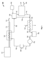
- FIG. 1 shows a schematic of a waste heat recovery system 100 for an engine 110 according to an embodiment.
- the waste heat recovery system 100 may be implemented for an engine 110 mounted on a motor vehicle (not shown) to drive that vehicle, for example. Therefore, the engine 101 may comprise an IC engine, in particular a reciprocating piston engine.
- the vehicle may be an on-road truck, the operation of which is set out in the standard 'highway cycle' or World Harmonised Test Cycle (WHTC).
- WHTC World Harmonised Test Cycle
- the waste heat recovery system 100 may employ a fluid, such as water, an organofluorine such as Freon®, or a hydrocarbon such as ethanol, or the like as a working fluid.
- the fluid may change into different states such as liquid and gas as it recovers and converts waste heat from the engine 110 into work.
- a Rankine cycle may be employed to convert heat into work.
- the particular fluid used may vary from one application to another.
- the waste heat recovery system 100 may include at least one evaporator 120, a bypass valve 130, and an expander 140 to recover and convert heat from the engine 110 into work.
- the waste heat recovery system 100 may also include a condenser 150 and a reservoir 160 to cool the fluid for reuse in the waste heat recovery system 100.
- the waste heat recovery system 100 may also include a fluid pump 170 and a flow control module 180 to provide and control the flow of the fluid to the evaporator 120 and through the waste heat recovery system 100 as will be described in the following prior to discussing the bypass valve 130 in more detail.
- the engine 110 may be coupled to an exhaust pipe 112 which carries a vehicle exhaust 114.
- the vehicle exhaust 114 may have waste heat generated by the engine 110.
- the engine 110 may be any source of waste heat such as a turbine, electrical motor, etc.
- the engine 110 may be an IC engine.
- an exhaust pipe 112 carries the vehicle exhaust 114 which may have the waste heat.
- the evaporator 120 is depicted as recovering the waste heat from the vehicle exhaust 114 flowing through the exhaust pipe 112, any suitable source of waste heat generated by the engine 110 may be recovered by the waste heat recovery system 100. For example, heat may be recovered from the engine 110's exhaust gas recirculation system (EGR).
- EGR exhaust gas recirculation system
- the evaporator 120 may use the waste heat from the engine 110 to convert the fluid to a superheated vapor although the fluid may be converted into any suitable form.
- the evaporator 120 may be any device suitable to convert the fluid.
- the evaporator 120 is in fluid communication with the bypass valve 130 via a fluid line 122.
- the evaporator outlet 122 fluid may be a superheated vapor entering the bypass valve 130 at approximately 400°C (752°F) and 40 bar (580 psi) although any suitable temperature and pressure may be employed.
- the foregoing temperatures and pressures are exemplary embodiments and do not limit the scope of this and other embodiments.
- the bypass valve 130 may provide a fluid flow from the evaporator 120 to the condenser 150 and/or the expander 140.
- the expander inlet 132 fluid enters the expander 140 which converts heat energy in the fluid into work 144.
- the bypass valve 130 is described in more detail with reference to FIGS. 2a-4b .
- the expander inlet 132 fluid flows into the expander 140 where it may reduce in enthalpy while expanding. Therefore, the expander 140 can convert at least some of the energy of the fluid to the work 144.
- the work 144 may be in the form of a mechanical motion.
- the expander 140 may comprise a variety of devices, such as a turbine, a piston, a vapor engine, such as a rotary vane type vapor engine, etc. In the depicted embodiment the expander 140 may comprise the vapor engine.
- the expander 140 can be mechanically coupled to the crankshaft or other suitable component of the engine 110 in order to add power to the engine 110.
- the engine 110 may or may not be mechanically decoupled from the expander 140.
- the fluid may flow from the expander 140 via the expander outlet 142 and combine with the bypass condenser outlet 134 fluid before flowing into the condenser 150.
- the bypass condenser outlet 134 and the expander outlet 142 fluids are depicted as combining before entering the condenser 150, the bypass condenser outlet 134 and the expander outlet 142 fluids may flow into the condenser 150 separately.
- the bypass condenser outlet 134 may be coupled to the condenser 150 via a different port than the expander outlet 142.
- the condenser 150 may cool the bypass condenser outlet 134 and/or the expander outlet 142 fluids to a temperature suitable for the reservoir 160, the fluid pump 170 and/or the flow control module 180.
- the condenser 150 may cool the bypass condenser outlet 134 and/or the expander outlet 142 fluids to room temperature.
- the condenser 150 employs a coolant 154 to cool the bypass condenser outlet 134 and/or the expander outlet 142 fluids. Heat may be transferred out of the condenser 150 to the coolant 154 to cool the fluid.
- the cooled fluid may flow from the condenser 150 to the reservoir 160 via the condenser outlet 152.
- the fluid pump 170 may draw the fluid out of the reservoir 160.
- the fluid pump 170 can elevate the pressure of the fluid from the reservoir 160 to a higher threshold pressure.
- the fluid pump 170 may raise the pressure of the fluid to a threshold pressure of approximately 40 bar (580 psi) above the reservoir pressure, which may be at atmospheric pressure.
- a threshold pressure of approximately 40 bar (580 psi) above the reservoir pressure, which may be at atmospheric pressure.
- the fluid pump 170 may be driven by any suitable means.
- the fluid pump 170 may be driven by the engine 110 or may be driven by a separate electric motor.
- the fluid pump 170 may provide the pressurized fluid to the evaporator 120 via the flow control outlet 182.
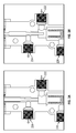
- FIG. 2a shows a perspective view of the bypass valve 130 provided according to an embodiment.
- the bypass valve 130 may bypass, regulate, and/or direct flow of the fluid to the expander 140.
- the bypass valve 130 may also regulate the fluid flows to the condenser 150.
- the bypass valve 130 may include an actuator housing 210 coupled to a valve housing 220 via a thermal isolation gasket 218.
- the actuator housing 210 may have one or more actuator ports 212 although two actuator ports 212 are depicted.
- the actuator housing 210 may also have a position sensor 214 coupled to the side of the actuator housing 210.
- the valve housing 220 may have a valve inlet 222, a bypass outlet 224, and an expander outlet 226.
- the bypass valve 130 may be coupled to something else, such as the engine 110, via the one or more bolt holes 228.
- FIG. 2b shows a cross-section view of the bypass valve 130 provided according to an embodiment.
- the bypass valve 130 includes a valve stem 230.
- the valve stem 230 includes a meter profile 232.
- the valve stem 230 may be coupled to a stem spring retainer 236.
- the stem spring 234 and stem spring retainer 236 are depicted as disposed in an actuation piston 238.
- the bypass valve 130 also includes a position sensor flag 270.
- the position sensor flag 270 may be comprised of a magnetic material that may be sensed by the position sensor 214.
- the valve stem 230 is slidably coupled to a bushing 240.
- the bushing 240 may be coupled to an inner surface of the valve housing 220.
- the bypass valve 130 also includes a valve seat 242 and a flow control orifice 244 on the valve housing 220.
- the bypass valve 130 may also include an expander poppet 250.
- the expander poppet 250 may be slidably coupled to a poppet retainer 260.
- a poppet shaft 252 may linearly move in a guide 262.
- the expander poppet 250 may also be coupled to the poppet retainer 260 via the expander poppet spring 254.
- the actuator housing 210 and the valve housing 220 are depicted as coupled together to form an outer housing of the bypass valve 130.
- the outer housing may be comprised of more or fewer parts in alternative embodiments.
- the valve housing 220 may be in two pieces where the two parts are mated between the valve inlet 222 and the expander outlet 226.
- the actuator housing 210 and the valve housing 220 may be made of stainless steel (e.g., 316 stainless steel) for corrosion and heat resistance properties although any suitable material may be employed.
- a ceramic material may be employed for high temperature waste heat recovery systems.
- the one or more actuator port 212 may be a fluid port that is fluidly coupled with a valve controller 136 described with reference to FIG. 1 .
- the one or more actuator port 212 are depicted as a fluid port that is fluidly coupled with the valve controller 136 any suitable means of coupling the bypass valve 130 to the valve controller 136 may be employed.
- the valve controller 136 may be a stepper driver/controller instead of a controller.
- the one or more actuator ports 212 may be electrical ports that receive stepper motor drive currents to move the valve stem 230.
- the valve controller 136 may be a proportional valve that regulates the flow of the fluid from the waste heat recovery system 100 to the bypass valve to move the piston 238 and/or valve stem 230. That is, the fluid in the waste heat recovery system 100 may actuate the bypass valve 130.
- the position sensor 214 may be a magnetic position sensor although any sensor may be employed.
- an optical position sensor may be employed although this may require that the actuator housing 210 include a transparent view port such as a quartz window.
- the position sensor 214 may sense the position of the valve stem 230 by sensing the position of the position flag 270.
- the valve inlet 222 may be in fluid communication with the evaporator 120.
- the bypass outlet 224 may be in fluid communication with the condenser 150.
- the expander outlet 226 may be in fluid communication with the expander 140.
- the valve inlet 222, the bypass outlet 224, and the expander outlet 226 are threaded fitting ports although any suitable means of fluidly coupling the bypass valve 130 with the expander 140 and the condenser 150 may be employed.
- the valve stem 230 may be adapted to displace the expander poppet 250.
- the valve stem 230 may also be adapted to regulate a bypass fluid flow.
- the bushing 240 may be adapted to guide the valve stem 230 in a substantially linear direction.
- the bushing 240 may be removable. That is, the bushing 240 may be replaced by separating the actuator housing 210 from the valve housing 220.
- the expander poppet 250 may be adapted to prevent the flow of the fluid to the expander 140.
- the expander poppet 250 may be adapted to prevent the flow of the fluid to the expander 140 when pressed against a portion of the valve housing 220.
- the valve stem 230, the bushing 240, and the expander poppet 250 may be comprised of stainless steel although any suitable material may be employed.
- the valve stem 230 may be comprised of a material with corrosion and wear resistance properties such as 420 stainless steel with a polished surface or other suitable wear resistant material or coating.
- the stem spring 234 and the stem spring retainer 236 may be adapted to press the valve stem 230 to a bypass flow position that is described in more detail below with reference to FIGS. 3a-3b .
- the stem spring 234 and the stem spring retainer 236 may be comprised of any suitable material such as stainless steel. Since, as will be explained in the following, the stem spring 234 and the stem spring retainer 236 may be isolated (e.g., thermally) from the fluid. Accordingly, the stem spring 234 and the stem spring retainer 236 may be selected for their mechanical properties.
- the actuation piston 238 may be adapted to press the valve stem 230 towards the expander poppet 250. In the embodiment shown, the actuation piston 238 surrounds the stem spring 234 and the stem spring retainer 236. The operation of the actuation piston 238 is described in more detail with reference to FIGS. 3a and 3b .
- bypass valve 130 may regulate the flow of fluid from the evaporator 120 by moving the valve stem 230.
- the bypass valve 130 may also regulate the flow of the fluid to the expander 140 and the condenser 150.
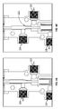
- FIG. 3a shows the bypass valve 130 in a bypass flow state according to an embodiment, the reference numbers below referring to the corresponding features shown in figures 2a and 2b .
- the valve stem 230 is positioned to maximize a bypass fluid flow.
- the maximized bypass fluid flow maximizes the flow to the condenser 150 via the bypass outlet 224.
- the valve stem 230 is depicted as fully withdrawn from the expander poppet 250.
- the flow control orifice 244 may be maximized.
- the expander poppet 250 is depicted as pressed into the actuator housing 210 by the expander poppet spring 254 to create a seal that may prevent the fluid from flowing through the expander outlet 226 towards the expander 140.
- the evaporator outlet 122 fluid may enter the valve inlet 222 and flow through the flow control orifice 244 past the meter profile 232.
- the bypass flow state may correspond to a maximum bypass flow rate. That is, the valve stem 230 is maximally displaced towards the actuator housing 210.
- the valve seat 242 may be configured such that when the valve stem 230 is in the depicted position, obstruction of the flow from the valve inlet 222 to the bypass outlet 224 is minimized.
- a different flow control orifice 244 may be used where the maximal flow through the bypass outlet 224 is at different valve stem 230 positions. For example, it may be desirable to have a maximal bypass flow when the valve stem 230 is positioned to switch the bypass valve 130 out flow from the valve inlet 222 to the bypass outlet 224.
- the valve stem 230 may move in the bypass valve 130 to regulate the flow of the fluid in the bypass valve 130, which is described in the following.
- FIG. 3b shows the bypass valve 130 in a regulated bypass flow state according to an embodiment, the reference numbers below referring to the corresponding features shown in figures 2a and 2b .
- the valve stem 230 is closer to the expander poppet 250. In this position, the flow control orifice 244 may be smaller than the flow control orifice 244 depicted in FIG. 3a .
- the valve stem 230 may be moved by the valve controller 136 which provides a pressurized fluid to the actuator housing 210. The pressurized fluid presses against the actuation piston 238 to compress the stem spring 234. By compressing the stem spring 234, the valve stem 230 is moved towards the expander poppet 250.
- the fluid flowing through the bypass outlet 224 may be regulated by the flow control orifice 244.
- the expander poppet 250 is depicted in FIG. 3b pressed against the valve housing 220 by the expander poppet spring 254.
- the fluid may not flow through the expander outlet 226 towards the expander 140.
- the fluid flowing through the bypass outlet 224 may be regulated by moving the valve stem 230 about the position depicted in FIG. 3b .
- the valve stem 230 may continue moving towards the expander poppet 250 to decrease the size of the flow control orifice 244 until the valve stem 230 seats on the expander poppet 250 as will be described in the following.
- FIG. 4a shows the bypass valve 130 in a seated regulated bypass flow state according to an embodiment, the reference numbers below referring to the corresponding features shown in figures 2a and 2b .
- the valve stem 230 is depicted as seated on the expander poppet 250.
- the expander poppet 250 is still pressed against the valve housing 220 by the expander poppet spring 254.
- the flow control orifice 244 may be smaller than depicted in FIGS. 3a and 3b .
- the seated regulated bypass flow state may therefore be a minimal bypass flow rate state. That is, the fluid flow rate from the evaporator 120 to the condenser 150 via the bypass outlet 224 may be at a minimum where there is also no fluid flowing to the expander 140.
- the valve seat 242 may be different in alternative embodiments and, therefore, the seated regulated bypass flow state may not be a minimal bypass flow rate state.
- FIG. 4b shows the bypass valve 130 in an expander flow state according to an embodiment, the reference numbers below referring to the corresponding features shown in figures 2a and 2b .
- the valve stem 230 is pressed into the valve housing 220 which may provide a fluid seal.
- the fluid seal may prevent the fluid from flowing from the valve inlet 222 towards the bypass outlet 224. Accordingly, fluid may not flow through the bypass outlet 224 towards the condenser 150.
- the expander poppet 250 is depicted as pressed by the valve stem 230 towards the poppet retainer 260.
- the guide 262 in the poppet retainer 260 may limit the lateral or rotational movement of the expander poppet 250 as it is pressed by the valve stem 230.
- the expander poppet spring 254 may press the expander poppet 250 towards the valve stem 230 which may cause the valve stem 230 to remain in contact with the expander poppet 250 as the valve stem 230 moves the expander poppet 250.
- the bypass valve 130 may cycle between the states depicted in FIGS. 3a - 4b .
- the bypass valve 130 may regulate the fluid flow from the evaporator 120 to the condenser 150 without fluid flow to the expander 140 by moving the valve stem 230 between the positions depicted in FIG. 3a and FIG. 4a .
- the flow control orifice 244 may change size thereby reducing or increasing the flow and/or pressure of the fluid to the condenser 150 via the bypass condenser outlet 134.
- flow through the bypass condenser outlet 134 may be regulated while fluid is flowing towards the expander 140.
- the valve stem 230 may be in a position that is between the position depicted in FIGS. 4a and 4b .
- the regulation of the flow through the bypass outlet 224 towards the condenser 150 may also regulate the flow towards the expander 140. That is, reducing the flow through the bypass outlet 224 may increase the flow through the expander outlet 226 towards the expander 140.
- the distance the valve stem 230 moves may be selected to provide the foregoing described states.
- the distance from the bypass state depicted in FIG. 3a and the expander flow state depicted in FIG. 4b may be selected along with the distance that the valve stem 230 travels before it touches the expander poppet 250.
- the distance the valve stem 230 moves between the bypass flow state and the expander flow state may be 25mm.
- the distance that the valve stem 230 can displace the expander poppet 250 may be 5 mm. Accordingly, the valve stem 230 may move within a 20 mm range to regulate the flow of the fluid to the bypass outlet 224 without flow to the expander 140.
- valve stem 230 While the valve stem 230 may be moved within the 5 mm displacement of the poppet 250 to regulate the flow of the fluid to the condenser 150 and the expander 140. When the valve stem 230 has displaced the expander poppet 250 the 5 mm towards the poppet retainer 260, the valve stem 230 may form a seal with the valve seat 242 as shown in FIG. 4b . Other lengths may be selected.
- the bypass valve 130 may allow the fluid to flow through the bypass valve 130.
- the fluid may flow to the condenser 150 through the bypass outlet 224 and/or to the expander 140 through the expander outlet 226.
- the valve stem 230 may never prevent the fluid from flowing through the bypass outlet 224 and the expander outlet 226.
- the valve stem 230 may always allow the fluid to flow from the evaporator 120 which may prevent pressure buildup in the evaporator 120 as the fluid converts from a fluid to a gas.
- the fluid may flow even though the bypass valve 130 may experience a failure.
- the valve controller 136 may unexpectedly fail and, therefore, is unable to move the valve stem 230. Even in such a situation, the fluid may still flow through the bypass valve 130 thereby preventing a pressure buildup in the evaporator 120. In effect, the bypass valve 130 may be considered fail safe.
- bypass valve 130 With the operation of the bypass valve 130 described in the foregoing, attention is now directed to the bypass valve 130's use in the waste heat recovery system 100.
- the waste heat recovery system 100 can be used in the waste heat recovery system 100 that, for example, is part of motor vehicles that include IC engines.
- the waste heat recovery system 100 can be controlled by the motor vehicle's electronics and therefore the waste heat recovery system 100 may not include its own separate electronics.
- a waste heat recovery system may employ its own controls.
- These control systems may control the position of the valve stem 230 in the bypass valve 130.
- the motor vehicle's control system may communicate (e.g., electronically) with the valve controller 136 to move the valve stem 230 between the positions depicted in FIGS. 3a - 4b to, for example, provide more work 144 to the engine 100.
- the bypass valve 130 may remain in the bypass flow state depicted in FIG. 3a when the work 144 is not desired or when the temperature of the fluid in the evaporator 120 has not reached the threshold temperature.
- the work 144 may not be desired when the vehicle is braking or stopped.
- a brake signal may automatically de-actuate the valve controller 136 thereby allowing the stem spring 234 to press the valve stem 230 to the bypass flow state or the regulated bypass flow state.
- the valve stem 230 may be moved to press the expander poppet 250 towards the poppet retainer 260 to allow heated fluid (e.g., superheated vapor) to flow to the expander 140.
- heated fluid e.g., superheated vapor
- the position of the valve stem 230 may be controlled by the valve controller 136 as described in the foregoing.
- the expander 140 may convert the fluid's heat energy into the work 144.
- the amount of work 144 that is produced may be controlled by the position of the valve stem 230. For example, if more work 144 is desired the valve stem 250 may fully depress the expander poppet 250 to prevent heated fluid from flowing through the bypass outlet 224. Therefore, the bypass valve 130 may direct fluid flow to the expander 140 to convert waste heat from the engine 110 into work 144.
- the work 144 may be employed by the vehicle or any other suitable system, apparatus, etc.
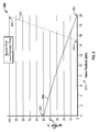
- FIG. 5 shows a graph 500 depicting exemplary flows through the bypass valve 130 according to an embodiment.
- the graph 500 includes a valve position 510 and a percentage of full flow 520 axes.
- the valve position 510 is depicted in mm units although any suitable measurement system may be employed. Also, the position ranges from 0 to 25 mm which corresponds to the valve stem 230 positions described with respect to FIGS. 3a-4b .
- the percentage of full flow refers to the percentage of flow possible through the bypass valve 130 which may correspond to the expander flow state depicted in FIG. 4b .
- the graph 500 also includes an expander flow rate line 540 and a bypass flow rate line 550.
- the expander flow rate line 540 includes a poppet open transition 542 and a 100% expander flow 544 regions.
- the poppet open transition 542 may correspond to the seated regulated bypass flow state depicted in FIG. 4a .
- the 100% expander flow 544 region may correspond to the expander flow state depicted in FIG. 4b .
- the bypass flow rate line 550 includes a 50% flow rate 552 and a 0% flow rate 554 regions. The 50% flow rate 552 region corresponds to when the valve stem 230 is in the position depicted in FIG. 3a .
- the expander flow rate line 540 corresponds with fluid flow through the expander outlet 226.
- the bypass flow rate line 550 corresponds with fluid flow through the bypass outlet 224.
- the fluid flow through the bypass valve 130 is through bypass outlet 224 and/or the expander outlet 226.
- the expander flow rate line 540 and the bypass flow rate line 550 shows that the expander outlet 226 flow rate increases relatively faster than the bypass outlet 224 flow rate.
- the expander flow rate line 540 is flat until the poppet open transition 542 occurs.
- the bypass flow rate line 550 decreases from about the 50% flow rate 552 to about 0% flow rate 554. This is also the same position on the valve position 510 axis where the expander flow rate line 540 reaches 100% fluid flow.
- bypass valve 130 there may always be fluid flow through the bypass valve 130 which may be intrinsically or fail safe.
- the fluid flow through the bypass valve 130 is also regulated as can be observed by the linear fluid flow rates. Although linear fluid flow rates are depicted in the graph 500, other fluid flow rates may be employed. For example, it may be desirable to have curvilinear fluid flow rates.
- the position of the valve stem 230 may be determined on the basis of a variety of other parameters.
- the valve stem 230 position may also be controlled to regulate the temperature and pressure of the evaporator outlet 122 fluid. While the valve stem 230 is being positioned to regulate the temperature and pressure of the fluid in the evaporator 120, the heated fluid may not be flowing to the expander 140. Accordingly, the fluid in the evaporator 120 may reach a temperature and pressure that utilizes the expander 140 at a desired efficiency.
- the efficiency of the expander 140 may depend on the temperature and pressure of the fluid that enters the expander 140.
- the position of the valve stem 230 may also be controlled to utilize the condenser 150 in a desired manner (e.g., to extend the life of the condenser 150, maintain a desired fluid temperature in the condenser 150, etc.)
- the bypass valve 130 may regulate a flow of the heated fluid in a waste heat recovery system.
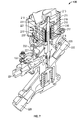
- FIGS. 6A and 6B show a bypass valve 700 according to another embodiment.
- the bypass valve 700 may include a valve housing 710 with an actuator port 712, an inlet 714, a bypass outlet 716, and an expander outlet 718.
- the valve housing 710 may also include a two way breather 719 to allow fluid to flow to and from valve housing 710.
- the bypass valve 700 may include an actuator seal 720 that separates an actuator portion 710a from the regulating portion 710b of the valve housing 710.
- the fluid in the actuator portion 710a of the valve housing 710 may be pressurized fluid to actuate the bypass valve 700.
- the fluid in the actuator portion 710a may be pressurized air.
- the valve housing 710 may also include a two way breather 719.
- the fluid in the regulating portion 710b of the valve housing 710 may be the working fluid that is regulated by a stem 730.
- the stem 730 may be slidably coupled to the valve housing 710 and coupled to the actuator seal 720 at the stem seal 732.
- the bypass valve 700 may also include a piston 740 that is coupled to the stem 730 and a return spring 750.
- the return spring 750 may provide a biasing force to oppose the pressurized fluid in the actuator portion 710a of the valve housing 710.
- the bypass valve 700 may also comprise a poppet 760 that is slidably coupled to the valve housing 710.
- the valve housing 710 may be fluidly coupled to the evaporator(s) 120 and to the expander 140 and the condenser 150.
- the inlet 714 may be fluidly coupled to the evaporator(s) 120.
- the bypass outlet 716 may be fluidly coupled to the condenser 150 and the expander outlet 718 may be fluidly coupled to the expander 140.
- the expander 140 and the condenser 150 may therefore be in selective and proportional fluid communication with the evaporator(s) 120 via the bypass valve 700.
- the valve housing 710 may also enclose pressurized fluid in the actuator portion 710a to actuate the bypass valve 700 to regulate fluid flow to the expander 140 and the condenser 150.
- the pressurized fluid in the actuator portion 710a of the valve housing 710 and the working fluid in the regulating portion 710b of the valve housing 710 may be separated by the actuator seal 720.
- the actuator seal 720 may be a static fluid seal that separates fluid in the actuator portion 710a from the fluid in the regulating portion 710b of the valve housing 710.
- the actuator seal 720 may include a membrane, which may comprise a bellows 722 that allows the stem 730 to move to regulate the fluid in the bypass valve 700. That is, even though the bellows of the actuator seal 720 is coupled to the stem 730 to form a static seal at the stem seal 732, the stem 730 may still move linearly in the valve housing 710 to regulate the flow of the fluid.
- the movement of the stem 730 may be seen in the difference between the figures shown in FIGS. 6A and 6B .
- the movement stretches the bellows 722. During this movement, fluid under the piston 740 may pass through the two way breather 719 to prevent buildup of undesirable fluid pressure under the piston 740.
- the stem 730 may be a proportional flow stem that regulates the flow of the fluid to the expander 140 and/or the condenser 150.
- the stem 730 may include a profile that is adapted to change the size of an opening between the stem 730 and the valve housing 710 to regulate the flow of the fluid by moving the stem 730 in the bypass valve 700.
- the piston 740 may be coupled to the stem 730 with a screw 742 although any suitable means of coupling may be employed.
- the piston 740 may include seals 744 that allow the pressurized fluid to press the piston 740 towards the poppet 760.
- the stem 730 may be returned to position shown in FIG. 6A by the return spring 750.
- the stem 730 may also be adapted to displace the poppet 760.
- the poppet 760 may prevent the flow of the working fluid to the expander 140 to ensure that the working fluid does not have conditions that are unsuitable when the working fluid is supplied to the expander 150.
- the poppet 760 may be closed if the working fluid is not fully vaporized (e.g., has liquid droplets.)
- the poppet 760 may be opened by the stem 730 when the working fluid is fully vaporized and at a desirable temperature.
- the poppet 760 may be pressed against the valve housing 710 or the stem 730 by the poppet spring 752.
- the bypass valve 700 may regulate the flow of the working fluid in the waste heat recovery system 100 without an atmospheric dynamic seal.
- the actuator seal 720 separates the working fluid in the regulating portion 710b from the actuator portion 710a. Accordingly, the stem 730 may be moved by means other than the working fluid, such as pressurized air, without an atmospheric dynamic seal. For example, pressurized air may enter the inlet 712 and press against the piston 740 to move the stem 730 towards the poppet 760. This may reduce the flow of the fluid to the condenser 150.
- the return spring 750 may press against the pressurized fluid.
- the pressure in the pressurized fluid may be varied by, for example, a controller (not shown) that moves the stem 730 in the bypass valve 700.
- the actuator portion 710a may include, for example, an electric actuator utilizing a linear drive motor instead of the piston 740.
- the stem 730 may be moved by a linear drive motor.
- An alternative embodiment may employ a hydraulic actuation mechanism, which may employ as the hydraulic fluid the working fluid of the waste heat recovery cycle or a different fluid from a separate hydraulic circuit to the waste heat recovery cycle.
- the bypass valve 700 may regulate the flow of the working fluid in the waste heat recovery system 100 with no dynamic seals to atmosphere.
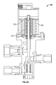
- FIG. 7 is a perspective sectional view of another embodiment of a bypass valve 130 according to the invention and including an actuator housing 210 sealingly coupled to a valve housing 220 via gasket 218.
- Actuator housing 210 and valve housing 220 are clamped together by a V-section band 233, which may be a simple deformed band.
- a clamp offers freedom of orientation between elements, a centralising effect for multiple elements being clamped, consistent clamping range over different temperature ranges of different clamp elements and avoidance of thread galling.
- Actuator housing 210 comprises a pneumatic cylinder 213 accommodating a piston 211 attached to one, upper end of a rod 215, the other, lower end of which engages the upper end of valve stem 230 by means of a blind bore 231.
- a tubular bellows 217 made from metal e.g. steel, is sealed between the lower end 215' of the rod 215 and the outside of the bore 219 through which the rod 215 passes into the cylinder 213.
- the metal bellows could be made from other materials.
- the bellows 217 is arranged such that the pressure of the working fluid acts on the outside of the bellows, which beneficially affects the life of the bellows.
- the bore is vertically offset from the lower end of the actuator housing (by means of tubular extension 221), with the result that the bellows also sit within the envelope of the actuator housing.
- valve housing 220 The arrangement of the valve housing 220 is similar to that of embodiments above, with a valve inlet 222, a bypass outlet 224, and an expander outlet 226 controlled by the valve stem 230.
- the valve housing 220 also includes a flow connection 227 that connects the region adjacent the upper portion 230of the valve stem 230 (and outside of the bellows) to a region of lower pressure downstream of the bypass outlet 224. This reduces the pressure of any working fluid at the upper region of the valve stem on the bellows 217. This eliminates high and variable pressures of working fluid that could limit the life of the bellows and improves control of the valve. As shown, conduit connects downstream of a convergent-divergent venturi 132 in the bypass outlet 224; however, this pressure relieving connection could be connected to alternative low pressure locations in the circuit.
- stem 230 has a specific control stem profile, with seats at both travel limits to limit the build-up of pressure from the working fluid on the bellows 217.
- the stem has a low leakage bushing and sealing at both ends.
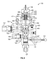
- FIG. 8 shows a cross-sectional view of the vapor control module 103 according to an embodiment.
- the vapor control module 103 when in a first position comprises a housing 403, which houses the bypass valve 128.
- the bypass valve 128 can include a biasing member 460, which can bias a valve member 461 towards a first position.
- the valve member 461 can open a fluid communication path between the inlet port 127 and the first outlet port 157 and close a fluid communication path between the inlet port 127 and the second outlet port 158.
- between the inlet port 127 and the outlet port 157 is a needle valve 131.
- the needle valve 131 can be provided to control the flow rate and pressure through the vapor control module 103.
- the needle valve 131 can be adjusted by actuating the adjustor 431. As shown, when the bypass valve 128 is in the first position, fluid can flow from the inlet port 127, through the needle valve 131 to a bypass fluid chamber 462.
- the valve member 461 includes a valve seal 463, which is located within the bypass fluid chamber 462 and is configured to seal against a valve seat 464. However, when the bypass valve 128 is actuated to the first position, the valve seal 463 is moved away from the valve seat 464.
- the superheated fluid flows into the venturi 132 downstream from the bypass fluid chamber 462.
- the venturi 132 can further reduce the pressure of the superheated fluid and increase the velocity of the superheated fluid before exiting the second outlet port 157 and flowing to the condenser 150.
- the superheated fluid may increase to a sonic velocity, for example.
- the vapor control module 103 can further include an injection port 465, which can receive cooling fluid from the fluid supply 104 via the cooling valve 133. When the cooling valve 133 is actuated, the cooling liquid can flow into the vapor control module 103 at the venturi 132 of the bypass circuit 130.
- the cooling liquid is better dispersed and therefore, the cooling efficiency is increased. Therefore, prior to the fluid leaving the outlet port 157, the superheated fluid cooled. This feature helps reduce the thermal shock experienced by the condenser 150.
- a flow control valve 142 may regulate the flow of the fluid from the cooling valve 133 to the injection port 465.
- the flow control valve 142 may control the flow based on parameters in the waste heat recovery system 100 and/or the engine 101.
- a temperature gauge 144 may provide a temperature of fluid in the bypass circuit 130.
- the flow control valve 142 may control the flow of the fluid to the injection port based on the temperature of the fluid in the bypass circuit 130.
- the flow control valve 142 may also control the flow based on the engine's 101 power output.
- the flow control valve 142 may increase the flow to the bypass circuit 130 when the engine's 101 power output drops due to the vehicle slowing due to the operator releasing the gas pedal.
- the cooling fluid may enter the bypass circuit 130 to cool the superheated fluid when the vapor control module 103 diverts the superheated fluid flow from the expander 140 to the bypass circuit 130.
- the bypass valve 128 can also be actuated to a second position. In the second position, fluid flows from the inlet port 127 to the second outlet port 158 towards the expander 140.
- the pilot supply valve 137 can be actuated from the default, first position, to a second position.
- the exhaust valve 138 can also be actuated to a second position to close the exhaust valve 138.
- the pilot supply valve 137 and the exhaust valve 138 can be replaced with a single 3/2-way valve or some other single valve configuration.
- fluid pressure is supplied to the pilot valve actuator 139.
- pressurized fluid supplied to the pilot valve actuator 139 acts on a piston member 439.
- the biasing force of the biasing member 460 and the fluid pressure acting on the valve member 461 is overcome to move the valve member 461 towards a second position (down according to the orientation shown).
- the valve seal 463 seals against the valve seat 464 and a second valve seal 466 unseats from a second valve seat 467.
- fluid can flow from the inlet port 127 towards the second outlet port 158 and towards the expander 140.
- the valve seal 463 sealed against the valve seat 464 fluid is substantially prevented from flowing directly to the condenser 150.
- the valve seal 463 ideally forms a completely fluid-tight seal, even if a small amount of fluid escapes past the valve seal 463, the fluid will simply flow to the condenser 150 and thus, a pressure will not build up in the bypass fluid chamber 462.
- the vapor control module 103 must be able to withstand the extreme pressures and temperatures of the superheated vapor flowing from the evaporator(s) 120. Therefore, a number of features are included in the vapor control module 103 to accommodate such extreme conditions.
- the sealing performed by the bypass valve 128 can be accomplished with metal-to-metal sealing. Therefore, the valve seals 463 and 466 along with the valve seats 464, 467 can all comprise a metal. Those skilled in the art will readily appreciate suitable metals. Furthermore, because of the poppet nature of the valve seals 463, 466 and valve seats 464, 467, little pressure drop is experienced through the bypass valve 128 when in the second position.
- the pilot valve actuator 139 is designed to limit the heat transferred to the elastomeric seal 468 and guide ring 469 used for the piston 439.
- the pilot valve actuator 139 can include a plurality of heat fins 470.
- heat fins can aid in dissipating heat by increasing the surface area of the component. Therefore, the heat fins 470 can remove some of the heat experienced by the contact between the housing 403 and the pilot valve actuator 139.
- the pilot valve actuator 139 can be coupled to the housing 403 using brackets 471.
- the brackets 471 can create an air gap 472 to further increase the surface area of the pilot valve actuator 139. This minimizes the surface area of contact between the pilot valve actuator 139 and the housing 403.
- the bypass valve 130 is described in the foregoing as being employed in the exemplary waste heat recovery system 100. However, the bypass valve 130 may be employed in a variety of waste heat recovery systems different from the waste heat recovery system 100 depicted in FIG. 1 . For example, the bypass valve 130 may regulate the flow of the heated fluid in another waste heat recovery system that employs additional valves that regulate the flow of fluids to the evaporator 120. That is, the bypass valve 130 may regulate the flow of the fluid in conjunction with other valves. The bypass valve 130 may also be employed in waste heat recovery systems that employ a variety of temperature sensors to control the position of the valve stem 230.
Landscapes
- Engineering & Computer Science (AREA)
- General Engineering & Computer Science (AREA)
- Chemical & Material Sciences (AREA)
- Combustion & Propulsion (AREA)
- Mechanical Engineering (AREA)
- Lift Valve (AREA)
- Engine Equipment That Uses Special Cycles (AREA)
- Fluid-Driven Valves (AREA)
Applications Claiming Priority (6)
| Application Number | Priority Date | Filing Date | Title |
|---|---|---|---|
| US201261714964P | 2012-10-17 | 2012-10-17 | |
| US201361823102P | 2013-05-14 | 2013-05-14 | |
| US201361828260P | 2013-05-29 | 2013-05-29 | |
| US201361844973P | 2013-07-11 | 2013-07-11 | |
| US201361846504P | 2013-07-15 | 2013-07-15 | |
| EP13795849.2A EP2917513A2 (fr) | 2012-10-17 | 2013-10-17 | Soupape de dérivation |
Related Parent Applications (1)
| Application Number | Title | Priority Date | Filing Date |
|---|---|---|---|
| EP13795849.2A Division EP2917513A2 (fr) | 2012-10-17 | 2013-10-17 | Soupape de dérivation |
Publications (1)
| Publication Number | Publication Date |
|---|---|
| EP2993317A1 true EP2993317A1 (fr) | 2016-03-09 |
Family
ID=49667513
Family Applications (2)
| Application Number | Title | Priority Date | Filing Date |
|---|---|---|---|
| EP13795849.2A Withdrawn EP2917513A2 (fr) | 2012-10-17 | 2013-10-17 | Soupape de dérivation |
| EP15185521.0A Withdrawn EP2993317A1 (fr) | 2012-10-17 | 2013-10-17 | Soupape de derivation |
Family Applications Before (1)
| Application Number | Title | Priority Date | Filing Date |
|---|---|---|---|
| EP13795849.2A Withdrawn EP2917513A2 (fr) | 2012-10-17 | 2013-10-17 | Soupape de dérivation |
Country Status (6)
| Country | Link |
|---|---|
| US (1) | US9964229B2 (fr) |
| EP (2) | EP2917513A2 (fr) |
| JP (1) | JP6314146B2 (fr) |
| BR (1) | BR112015008597A2 (fr) |
| CA (1) | CA2888113A1 (fr) |
| WO (1) | WO2014060760A2 (fr) |
Families Citing this family (21)
| Publication number | Priority date | Publication date | Assignee | Title |
|---|---|---|---|---|
| WO2013030397A1 (fr) * | 2011-09-02 | 2013-03-07 | Aurotec Gmbh | Conduite avec soupape de surpression |
| MX2016011024A (es) | 2014-02-28 | 2017-03-15 | Project Phoenix Llc | Bomba integrada con dos motores primarios impulsados de manera independiente. |
| EP3123029B1 (fr) | 2014-03-25 | 2024-03-20 | Project Phoenix, LLC | Système de pompage de fluide et commande associée |
| WO2015164453A2 (fr) | 2014-04-22 | 2015-10-29 | Afshari Thomas | Système de distribution de fluide doté d'un arbre ayant un passage traversant |
| EP3149343B1 (fr) | 2014-06-02 | 2020-06-17 | Project Phoenix LLC | Ensemble actionneur linéaire et système d'actionneur linéaire |
| US10544861B2 (en) | 2014-06-02 | 2020-01-28 | Project Phoenix, LLC | Hydrostatic transmission assembly and system |
| BR112017001234B1 (pt) | 2014-07-22 | 2022-09-06 | Project Phoenix, LLC | Bomba com invólucro de autoalinhamento e método de transferir fluido de uma porta de entrada para uma porta de saída de uma bomba incluindo um invólucro de bomba |
| US10072676B2 (en) | 2014-09-23 | 2018-09-11 | Project Phoenix, LLC | System to pump fluid and control thereof |
| US10539134B2 (en) | 2014-10-06 | 2020-01-21 | Project Phoenix, LLC | Linear actuator assembly and system |
| EP3209885A1 (fr) | 2014-10-20 | 2017-08-30 | Project Phoenix LLC | Ensemble et système de transmission hydrostatique |
| GB201505231D0 (en) * | 2015-03-27 | 2015-05-13 | Norgren Ltd C A | Heat energy recovery |
| TWI777234B (zh) | 2015-09-02 | 2022-09-11 | 美商鳳凰計劃股份有限公司 | 泵送流體之系統及其控制 |
| EP3344853B1 (fr) | 2015-09-02 | 2020-11-04 | Project Phoenix LLC | Système de pompage de fluide et commande associée |
| GB201603394D0 (en) * | 2016-02-26 | 2016-04-13 | Norgren Ltd C A | Improved vapour control valve |
| US10421478B2 (en) * | 2016-08-08 | 2019-09-24 | Deere & Company | Hydraulic bi-directional flow switches |
| WO2018035244A1 (fr) | 2016-08-17 | 2018-02-22 | Project Phoenix, LLC | Accumulateur actionné par un moteur |
| FR3067385B1 (fr) | 2017-06-13 | 2021-05-21 | Exoes | Machine de detente et procedes d'utilisation d'une telle machine |
| CN108644413B (zh) * | 2018-07-19 | 2024-04-26 | 宁波丽辰电器有限公司 | 一种分流阀 |
| US11808452B2 (en) | 2019-07-19 | 2023-11-07 | Robertshaw Controls Company | Intermittent pilot ignition gas valve having protection against negative pressure for internal diaphragms |
| CN114576391B (zh) * | 2022-03-22 | 2023-09-08 | 英特尔产品(成都)有限公司 | 用于对流体阀进行操作的方法及系统 |
| CN115875482B (zh) * | 2023-01-06 | 2023-05-02 | 山东益凯德液压股份有限公司 | 一种液压分流阀 |
Citations (9)
| Publication number | Priority date | Publication date | Assignee | Title |
|---|---|---|---|---|
| GB964194A (en) * | 1961-10-30 | 1964-07-15 | Concordia Masch & Elekt | Improvements in double beat lift valves |
| US4031705A (en) | 1974-11-15 | 1977-06-28 | Berg John W | Auxiliary power system and apparatus |
| DE29712083U1 (de) * | 1997-07-09 | 1997-09-11 | Kuhnke Gmbh Kg H | Mehrwegeventil |
| US20040255587A1 (en) * | 2003-06-17 | 2004-12-23 | Utc Power, Llc | Organic rankine cycle system for use with a reciprocating engine |
| US20060266960A1 (en) * | 2005-05-31 | 2006-11-30 | Fisher Controls International Llc | Pneumatic pilot valve |
| US20110203278A1 (en) * | 2010-02-25 | 2011-08-25 | General Electric Company | Auto optimizing control system for organic rankine cycle plants |
| WO2012018004A1 (fr) * | 2010-08-02 | 2012-02-09 | 三菱重工業株式会社 | Installations d'usine de production d'énergie et procédé de commande de ces installations |
| WO2012033010A1 (fr) * | 2010-09-06 | 2012-03-15 | 三菱重工業株式会社 | Ensemble centrale électrique, navire équipé de cet ensemble et procédé d'exploitation de l'ensemble de centrale électrique |
| EP2436888A1 (fr) * | 2010-09-24 | 2012-04-04 | Kabushiki Kaisha Toyota Jidoshokki | Système de cycle de Rankine |
Family Cites Families (9)
| Publication number | Priority date | Publication date | Assignee | Title |
|---|---|---|---|---|
| JPS5125834A (fr) * | 1974-08-28 | 1976-03-03 | Mitsubishi Motors Corp | |
| JPS6025020Y2 (ja) * | 1982-03-31 | 1985-07-26 | アイシン精機株式会社 | サ−モバルブ |
| JPS6138371A (ja) * | 1984-07-31 | 1986-02-24 | 株式会社 鷺宮製作所 | 電動式流量調節弁 |
| DE202005016372U1 (de) * | 2005-10-19 | 2006-01-12 | Jeuken, Dieter | Strömungsventil, insbesondere zum Einsatz in einem Heizungskreislauf |
| WO2009038777A1 (fr) * | 2007-09-18 | 2009-03-26 | Vast Power Portfolio, Llc | Récupération d'huiles lourdes avec de l'eau fluide et du dioxyde de carbone |
| JP2008038916A (ja) | 2007-09-28 | 2008-02-21 | Denso Corp | ランキンサイクル |
| AU2009282872B2 (en) * | 2008-08-19 | 2014-11-06 | Waste Heat Solutions Llc | Solar thermal power generation using multiple working fluids in a Rankine cycle |
| US20100326076A1 (en) * | 2009-06-30 | 2010-12-30 | General Electric Company | Optimized system for recovering waste heat |
| DE102011105709A1 (de) * | 2011-06-22 | 2012-12-27 | Man Truck & Bus Ag | Verfahren und Vorrichtung zur Rückgewinnung von Wärme und deren Umwandlung in mechanische Leistung in einem Antriebssystem für Kraftfahrzeuge |
-
2013
- 2013-10-17 WO PCT/GB2013/052713 patent/WO2014060760A2/fr active Application Filing
- 2013-10-17 EP EP13795849.2A patent/EP2917513A2/fr not_active Withdrawn
- 2013-10-17 BR BR112015008597A patent/BR112015008597A2/pt not_active IP Right Cessation
- 2013-10-17 EP EP15185521.0A patent/EP2993317A1/fr not_active Withdrawn
- 2013-10-17 US US14/435,033 patent/US9964229B2/en not_active Expired - Fee Related
- 2013-10-17 CA CA2888113A patent/CA2888113A1/fr not_active Abandoned
- 2013-10-17 JP JP2015537348A patent/JP6314146B2/ja active Active
Patent Citations (9)
| Publication number | Priority date | Publication date | Assignee | Title |
|---|---|---|---|---|
| GB964194A (en) * | 1961-10-30 | 1964-07-15 | Concordia Masch & Elekt | Improvements in double beat lift valves |
| US4031705A (en) | 1974-11-15 | 1977-06-28 | Berg John W | Auxiliary power system and apparatus |
| DE29712083U1 (de) * | 1997-07-09 | 1997-09-11 | Kuhnke Gmbh Kg H | Mehrwegeventil |
| US20040255587A1 (en) * | 2003-06-17 | 2004-12-23 | Utc Power, Llc | Organic rankine cycle system for use with a reciprocating engine |
| US20060266960A1 (en) * | 2005-05-31 | 2006-11-30 | Fisher Controls International Llc | Pneumatic pilot valve |
| US20110203278A1 (en) * | 2010-02-25 | 2011-08-25 | General Electric Company | Auto optimizing control system for organic rankine cycle plants |
| WO2012018004A1 (fr) * | 2010-08-02 | 2012-02-09 | 三菱重工業株式会社 | Installations d'usine de production d'énergie et procédé de commande de ces installations |
| WO2012033010A1 (fr) * | 2010-09-06 | 2012-03-15 | 三菱重工業株式会社 | Ensemble centrale électrique, navire équipé de cet ensemble et procédé d'exploitation de l'ensemble de centrale électrique |
| EP2436888A1 (fr) * | 2010-09-24 | 2012-04-04 | Kabushiki Kaisha Toyota Jidoshokki | Système de cycle de Rankine |
Also Published As
| Publication number | Publication date |
|---|---|
| CA2888113A1 (fr) | 2014-04-24 |
| JP2015533396A (ja) | 2015-11-24 |
| BR112015008597A2 (pt) | 2017-12-19 |
| EP2917513A2 (fr) | 2015-09-16 |
| US20150330530A1 (en) | 2015-11-19 |
| JP6314146B2 (ja) | 2018-04-18 |
| US9964229B2 (en) | 2018-05-08 |
| WO2014060760A2 (fr) | 2014-04-24 |
| WO2014060760A3 (fr) | 2015-06-11 |
Similar Documents
| Publication | Publication Date | Title |
|---|---|---|
| US9964229B2 (en) | Bypass valve | |
| US20150267638A1 (en) | Vehicle waste heat recovery system | |
| US20180119592A1 (en) | Fluid control module for waste heat recovery systems | |
| EP2232021B1 (fr) | Systeme pneumatique de commande des soupapes d'un moteur a combustion interne | |
| CA2917075A1 (fr) | Clapet d'aiguillage d'echappement a battant | |
| US8438848B2 (en) | Engine with turbocharger and EGR | |
| JP6473147B2 (ja) | 燃焼機関及びそのためのマントルアセンブリ | |
| US9932863B2 (en) | Vehicle waste heat recovery system | |
| WO2003102386A1 (fr) | Dispositif et procede pour produire des impulsions de pression | |
| US20190048749A1 (en) | Waste heat recovery system | |
| WO2017144857A1 (fr) | Soupape de commande de vapeur améliorée | |
| WO2017144860A1 (fr) | Soupape distributrice | |
| US10322705B2 (en) | Pressure tapping device and motor vehicle having a pressure tapping device, and pressure tapping method | |
| US20190219180A1 (en) | Bypass valve for expansion machine | |
| US10247048B2 (en) | Gate valve | |
| WO2017077318A1 (fr) | Vanne de fluide | |
| JP2007120403A (ja) | 高温流体噴射弁及びこれを備えた高温水噴射内燃機関 |
Legal Events
| Date | Code | Title | Description |
|---|---|---|---|
| PUAI | Public reference made under article 153(3) epc to a published international application that has entered the european phase |
Free format text: ORIGINAL CODE: 0009012 |
|
| AC | Divisional application: reference to earlier application |
Ref document number: 2917513 Country of ref document: EP Kind code of ref document: P |
|
| AK | Designated contracting states |
Kind code of ref document: A1 Designated state(s): AL AT BE BG CH CY CZ DE DK EE ES FI FR GB GR HR HU IE IS IT LI LT LU LV MC MK MT NL NO PL PT RO RS SE SI SK SM TR |
|
| AX | Request for extension of the european patent |
Extension state: BA ME |
|
| 17P | Request for examination filed |
Effective date: 20160720 |
|
| RBV | Designated contracting states (corrected) |
Designated state(s): AL AT BE BG CH CY CZ DE DK EE ES FI FR GB GR HR HU IE IS IT LI LT LU LV MC MK MT NL NO PL PT RO RS SE SI SK SM TR |
|
| STAA | Information on the status of an ep patent application or granted ep patent |
Free format text: STATUS: THE APPLICATION HAS BEEN WITHDRAWN |
|
| 18W | Application withdrawn |
Effective date: 20181018 |