EP2993131B1 - Ausfahrbarer mast mit autonomer spontaner ausfahrbewegung, und satellit, der mit mindestens einem solchen mast ausgestattet ist - Google Patents
Ausfahrbarer mast mit autonomer spontaner ausfahrbewegung, und satellit, der mit mindestens einem solchen mast ausgestattet ist Download PDFInfo
- Publication number
- EP2993131B1 EP2993131B1 EP15182588.2A EP15182588A EP2993131B1 EP 2993131 B1 EP2993131 B1 EP 2993131B1 EP 15182588 A EP15182588 A EP 15182588A EP 2993131 B1 EP2993131 B1 EP 2993131B1
- Authority
- EP
- European Patent Office
- Prior art keywords
- platform
- deployment
- deployable mast
- stages
- mast
- Prior art date
- Legal status (The legal status is an assumption and is not a legal conclusion. Google has not performed a legal analysis and makes no representation as to the accuracy of the status listed.)
- Active
Links
- 230000002269 spontaneous effect Effects 0.000 title claims description 6
- 230000001105 regulatory effect Effects 0.000 description 6
- 230000001360 synchronised effect Effects 0.000 description 6
- 238000004873 anchoring Methods 0.000 description 4
- YFXPPSKYMBTNAV-UHFFFAOYSA-N bensultap Chemical compound C=1C=CC=CC=1S(=O)(=O)SCC(N(C)C)CSS(=O)(=O)C1=CC=CC=C1 YFXPPSKYMBTNAV-UHFFFAOYSA-N 0.000 description 2
- 239000002131 composite material Substances 0.000 description 2
- 239000007769 metal material Substances 0.000 description 2
- OKTJSMMVPCPJKN-UHFFFAOYSA-N Carbon Chemical compound [C] OKTJSMMVPCPJKN-UHFFFAOYSA-N 0.000 description 1
- 229920000049 Carbon (fiber) Polymers 0.000 description 1
- 238000004026 adhesive bonding Methods 0.000 description 1
- 230000000903 blocking effect Effects 0.000 description 1
- 229910052799 carbon Inorganic materials 0.000 description 1
- 239000004917 carbon fiber Substances 0.000 description 1
- XLJMAIOERFSOGZ-UHFFFAOYSA-M cyanate Chemical compound [O-]C#N XLJMAIOERFSOGZ-UHFFFAOYSA-M 0.000 description 1
- 239000003822 epoxy resin Substances 0.000 description 1
- 230000002349 favourable effect Effects 0.000 description 1
- 239000000835 fiber Substances 0.000 description 1
- 238000012423 maintenance Methods 0.000 description 1
- 239000000463 material Substances 0.000 description 1
- 230000007935 neutral effect Effects 0.000 description 1
- 238000005457 optimization Methods 0.000 description 1
- 230000002093 peripheral effect Effects 0.000 description 1
- 229920000647 polyepoxide Polymers 0.000 description 1
- 230000000750 progressive effect Effects 0.000 description 1
- 238000011084 recovery Methods 0.000 description 1
- 229920005989 resin Polymers 0.000 description 1
- 239000011347 resin Substances 0.000 description 1
Images


Classifications
-
- B—PERFORMING OPERATIONS; TRANSPORTING
- B64—AIRCRAFT; AVIATION; COSMONAUTICS
- B64G—COSMONAUTICS; VEHICLES OR EQUIPMENT THEREFOR
- B64G1/00—Cosmonautic vehicles
- B64G1/22—Parts of, or equipment specially adapted for fitting in or to, cosmonautic vehicles
- B64G1/222—Parts of, or equipment specially adapted for fitting in or to, cosmonautic vehicles for deploying structures between a stowed and deployed state
- B64G1/2221—Parts of, or equipment specially adapted for fitting in or to, cosmonautic vehicles for deploying structures between a stowed and deployed state characterised by the manner of deployment
- B64G1/2222—Folding
- B64G1/2224—Folding about multiple axes
-
- B—PERFORMING OPERATIONS; TRANSPORTING
- B64—AIRCRAFT; AVIATION; COSMONAUTICS
- B64G—COSMONAUTICS; VEHICLES OR EQUIPMENT THEREFOR
- B64G1/00—Cosmonautic vehicles
- B64G1/22—Parts of, or equipment specially adapted for fitting in or to, cosmonautic vehicles
- B64G1/222—Parts of, or equipment specially adapted for fitting in or to, cosmonautic vehicles for deploying structures between a stowed and deployed state
- B64G1/2228—Parts of, or equipment specially adapted for fitting in or to, cosmonautic vehicles for deploying structures between a stowed and deployed state characterised by the hold-down or release mechanisms
-
- H—ELECTRICITY
- H01—ELECTRIC ELEMENTS
- H01Q—ANTENNAS, i.e. RADIO AERIALS
- H01Q1/00—Details of, or arrangements associated with, antennas
- H01Q1/12—Supports; Mounting means
- H01Q1/1235—Collapsible supports; Means for erecting a rigid antenna
Definitions
- the present invention relates to a deployable mast with autonomous spontaneous deployment and a satellite comprising at least one such mast. It applies in particular to the field of space equipment that must be deployed in orbit and more particularly to space equipment for satellites, such as sensors or antennas or instruments with long focal lengths such as telescopes for example.
- a deployable mast for connecting two spacecraft spaced several meters apart as disclosed in EP 1 676 776 generally consists of a plurality of mast segments stacked one above the other, hinged together and whose deployment is motorized. Each mast segment is generally composed of several rigid beams articulated by hinges and locked by bolts.
- This type of mast has the disadvantage of requiring the use of an engine for deployment and presents a significant mass problem and reliability of the joints.
- the beams being rigid, the mast occupies, in the stored position, a large space under the cap of a launcher.
- the space allocated to the deployable structures under the cap of a launcher being limited, it is important to reduce the size of the mast when it is in the stored position, so as to optimize the surface in the deployed position.
- the mast must have a ratio of the deployed length / stacked volume as high as possible while ensuring a low mass, stability and rigidity of the mast in the deployed position sufficiently high to be compatible space applications.
- the object of the invention is to provide a deployable mast not having the disadvantages of existing deployable masts, having the advantage of being compact, lightweight, simple to perform, having an optimization of the mast volume when stored under a launcher cap, enabling reliable long-orbit deployment and control of deployment without the use of an engine and allowing rigidity and stability of the mast when deployed.
- the invention relates to a self-expanding deployable mast autonomous comprising at least one elementary structural block having a longitudinal axis of deployment X, the elementary structural block having two platforms respectively lower and upper parallel to a YZ plane orthogonal to the axis X and N stages stacked one above the other parallel to the longitudinal deployment axis X, where N is greater than 1 and where i is between 1 and N-1.
- Each stage comprises at least six flexible longitudinal link arms articulated by tape-meters, which in the deployed position are in planes parallel to the X axis and are inclined on the X axis; the N stages are fixed together in pairs by means of connecting platforms parallel to the YZ plane, two contiguous lower and upper stages being angularly offset relative to one another by a rotation about the axis of Deployment X.
- the mast comprises means for regulating the speed of deployment of the mast, which comprise for example a motorized main pulley fixed to the lower platform, and non-motorized secondary pulleys adapted to be driven by the main pulley by means of least a cable or ribbon.
- the secondary pulleys can be attached to the upper platform and each connecting platform with the same cable or ribbon connecting secondary pulleys of the different platforms to the main pulley.
- the secondary pulleys are fixed to the lower platform, the main pulley is stepped and comprises as many stages as secondary pulleys, and the speed control means comprise as many cables or ribbons as secondary pulleys, respectively attached to the upper platform and to each connecting platform.
- the secondary pulleys are fixed to the lower platform, the main pulley is staggered and comprises as many stages as secondary pulleys, and the speed control means comprise as many cables or ribbons as secondary pulleys, respectively attached to the upper platform only.
- two adjacent lower and upper contiguous stages are fixed together by a common connecting platform to the two adjacent stages.
- each upper, lower and connecting platform comprises fixing lugs grouped in regularly distributed pairs, each fixing lug being dedicated to the attachment of an end of a connecting arm.
- the fixing lugs are oriented towards the outside of the mast and for each pair of fastening lugs, the connecting arms in the folded configuration are oriented at an angle of between 0 ° and 45 °. in the YZ plane, tangentially to the platform.
- the folding zones are typically located towards both ends of the link arm and at an intermediate zone, and the arcuate sections of the zones towards the ends can be reversed (diametrically opposite) with respect to the section of the intermediate zone.
- At least three pairs of fasteners are distributed around the lower and upper platforms, at least six pairs of fasteners are distributed around each connecting platform.
- the platforms are triangular the pairs of brackets are generally distributed at the vertices of the triangles but it is not essential.
- the deployable mast may have several identical structural blocks stacked one above the other.
- a deployment lock-release device is advantageously positioned on each connection platform for to allow, after the deployment of said platform, the release of the contiguous platform which is superior to it.
- connecting arms in the form of tape-meters have a profile varying according to the deployed or folded position of the connecting arms; according to a feature of the invention, the locking-release device comprises locking-releasing means according to said profile.
- the subject of the invention is also a satellite characterized in that it comprises at least one deployable mast with autonomous spontaneous deployment as described previously.
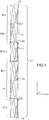
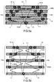
- the figure 1 illustrates an example of a deployable mast according to the invention, in the deployed position along a longitudinal deployment axis X, the mast comprising a multi-stage elementary structural block.
- An elementary structural block 10 is at least made up of a lower platform 13, an upper platform 12, one or more connecting platforms 15 and N stages E1, ..., Ei, Ei + 1, .. ., EN, where N is an integer greater than one and i is between 1 and N-1 inclusive, stacked one above the other parallel to the longitudinal deployment axis X and fixed rigidly between them two by two .
- Two adjacent stages E 1 and E 1 + 1 may be fixed to one another via a connecting platform 15 common to the two adjacent stages.
- the two lower platforms 13 and upper 12 and the connecting platforms 15 are parallel to a YZ plane orthogonal to the X axis; they are rigid and have a preferably symmetrical shape around the X axis such as for example a disk or ring shape, or may have a polygonal peripheral contour (triangular for example as shown in the figures) or circular.
- a stage of the elementary structural block 10 comprises at least six link arms equipped with tape-strips 11 which are deployed in planes parallel to the axis X and whose ends are respectively fixed. at an upper platform 12 or a lower platform 13 or a connecting platform 15.
- the tape measures are all identical, all have the same length and the same shape.
- Each connecting arm equipped with a tape measure has a lower end fixed rigidly to a platform of a lower floor Ei and one end upper fixed rigidly to a platform of an upper floor Ei + 1 contiguous to the lower floor Ei.
- each upper and lower platform and each connecting platform comprises fixing lugs 14 distributed on its periphery, each fixing lug being dedicated to the attachment of an end of a connecting arm equipped with tape measure.
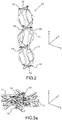
- the link arms articulated by tape-meters are in planes parallel to the X direction of deployment, but as illustrated figure 2 they do not deploy parallel to the X axis of the mast; deployed they are inclined with respect to X as can be seen on the figure 1 .
- This inclination allows the connecting arms equipped with tape measure to take the loads and moments applied to the platforms in the form of effort along their axis of deployment (that is to say according to their own neutral fiber) which is more favorable in terms of load recovery.
- the angle ⁇ is defined by the direction of a linking arm bent with respect to the tangent to a circle passing in a plane YZ by the anchoring zones of the fixing lugs. This angle ⁇ is typically determined as a function of the length of the mast, its volume in stored configuration and the desired rigidity.
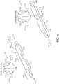
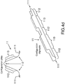
- the tape measures are known in the spatial field as flexible ribbons or strips having a convex first face 114, a concave second face 115 and having an arcuate section with a radius of curvature R, as represented for example in FIGS. Figures 4a and 4b .
- Tape meters have a natural tendency to extend longitudinally autonomously, mainly due to their own elastic energy without the use of an engine.
- connecting arms equipped with commercial tape-meters with a constant section along the entire length of the tape measure.
- ribbon meters which have an evolutionary section along their length in order to optimize the performances; typically the need for arcuate section is essential to the right folds.
- Each link arm has fold zones 112 articulated by tape-meters, which are located towards the two ends 111 and in an intermediate zone, and non-folding zones 113.
- the zones of non-folding 113 have a section with a circular arc longer than the arc of the folding zones 112 as shown figure 4d , and which can be maximal then forming a complete circle which then define tubular zones as shown figure 4c : This favors the buckling behavior.
- the arcuate sections of the end folding zones 111 can be inverted with respect to the section of the intermediate folding zone as shown. figure 4c This results in the same deployment force on all folded areas. When the arcuate sections are identical for all the folding zones, different deployment forces are obtained according to the folded zones.
- the connecting arm comprises a tape measure over its entire length.
- the tape measures can be oriented so as to have their concave face facing the outside of the mast, but it is also possible to orient them in the opposite direction so that they have their concave face oriented towards the inside of the mast.
- Each stage comprises at least six connecting arms 11 equipped with stretched tape-meters, in planes parallel to the longitudinal deployment axis X and inclined with respect to the X axis, the six connecting arms 11 equipped with tape measures 11 having two opposite ends respectively fixed on connecting platforms 15 or on the upper platform 12 or on the lower platform 13.
- the number of fastening lugs 14 of each connecting platform 15 is twice as large as the number of link arms 11 of a stage Ei of the elementary structural block 10.
- each connecting platform 15 comprises twelve fixing lugs grouped in six pairs, preferably evenly distributed around the platform three pairs on which are respectively fixed six link arms 11 of the lower stage Ei and three pairs on which are respectively fixed six link arms 11 of the upper contiguous stage Ei + 1.
- these six pairs are themselves grouped into three quadruplets 141 of fastening lugs that can be seen figure 3b .
- a stage comprising eight connecting arms will have twice four pairs of fixing lugs, preferably grouped into four quadruplets, etc.
- the fastening lugs 14 are oriented so that they extend outwardly of the elementary structural block 10 and thus towards the outside of the mast. They are integral with each link platform and are typically mounted on the outer periphery of each platform.
- the fastening lugs 14 secured to each connecting platform 15 may be located in the plane YZ of the connecting platform 15 corresponding or be inclined relative to the YZ plane of this platform, the inclination being oriented in opposite directions for the connecting arms of the upper stage Ei + 1 relative to the lower stage Ei.
- the fastening tabs of the connecting arms of the lower stage Ei may be inclined towards the top of the mast while the fixing lugs of the connecting arms of the upper stage Ei + 1 may be inclined towards the bottom of the mast, so as to create a longitudinal overlap zone 17 between two adjacent stages Ei and Ei + 1, which has the advantage of increasing the stiffness of the mast and of improving the compactness of the elementary structural block 10 when it is folded into position stored.
- Two consecutive connecting platforms 15, therefore belonging to the same stage Ei, and comprise fastening lugs oriented in opposite directions with respect to the YZ plane of the two connecting platforms.
- the fastening lugs 14 of a quadruplet are attached to the platform by means of an anchoring zone, for example with 5 branches distributed in a star, one in the extension of the periphery of the platform, the others dedicated to the four brackets as can be seen on the figure 3b , with two branches dedicated to the fixing of the tape-meters of the lower stage Ei, and the two other branches dedicated to the fixing of the tape-meters of the upper stage Ei + 1.
- the ends of the link arms 11 of each stage Ei can be fixed by embedding by means of flanges mounted on the attachment lugs 14 of the connecting platforms 15 or on the attachment lugs 14 of the upper or lower platforms 12 or 13, or can be fixed by riveting, screwing or gluing.
- the mast comprises several elementary structural blocks 10
- the lower platforms 13 and upper 12 located at the base and at the top of each elementary structural block 10 provide the connection between the connecting arms 11 of two consecutive elementary structural blocks.
- the fastening lugs 14 and the connecting arms 11 equipped with tape-meters 11 fixed thereto are regularly spaced around the longitudinal deployment axis X and for each connecting platform, the angles separating two quadruplets of fastening lugs may have identical values.
- Two contiguous stages are angularly offset relative to each other by a rotation about the deployment axis X so as to interpose the connecting arms equipped with tape-meters of a lower stage Ei between the connecting arms equipped with tape-meters of an upper contiguous stage Ei + 1, and inserting the fixing tabs of a lower stage Ei between the fastening tabs of an upper contiguous stage Ei + 1 and for between two consecutive platforms, the connecting arms equipped with tape-meters form inverted Vs and / or Vs figures.
- the elementary structural block 10 When an elementary structural block 10 is folded back into the stored position, it is in a compact state and all the upper, lower and connecting platforms 15 separating the different stages of the elementary structural block are stacked one above the other as shown on the views of figures 3a and 3b where we can see the connecting arms equipped with tape-meters folded towards the outside of the mast.
- the elementary structural block 10 comprises six stages with six connecting arms equipped with tape meters per stage, making a total of 36 connecting arms evenly distributed on the circumference of an annular ring consisting of a stack of all upper platforms , lower and bonding elementary structural block in the stacked state.
- the connecting arms 11 are folded in two on themselves in the direction of their length, the folding being carried outwardly of the mast with the fastening tabs extending towards the outside of the mast. as represented on the figures 3a and 3b .
- Two consecutive connecting platforms 15, therefore belonging to the same floor Ei, comprise anchoring zones whose spacing is determined so as to ensure maximum elastic folding of the connecting arms equipped with tape-meters. This spacing is identical for each pair of anchoring zones.
- the connecting arms 11 equipped with tape measures are made of a material compatible with a space environment and can be made of a metallic material or a composite material such as for example carbon fibers embedded in an epoxy resin or in a resin cyanate. Composite materials are preferred because they have a much lower coefficient of expansion than metal materials.
- the upper and lower platforms and the connecting platforms are preferably made of carbon.
- the mast has no hinge as such, nor hinge, nor pivot, nor deployment engine.
- all the link arms 11 equipped with tape measures 11 of all the elementary structural stages Ei store elastic energy due to the stresses that hold them in the folded position in two.
- the maintenance of the connecting arms 11 equipped with tape-meters in the folded position is provided by a stacking system maintaining the various platforms in stored configuration.
- the deployment of the mast is initiated by the release of the stacking system.
- the deployment is then carried out passively by loosening the stresses on the tape-meters during their unfolding and releasing the elastic energy stored by the tape-meters.
- speed control means are preferably used to control the deployment of the mast.
- the speed of the unfolding of the tape meters can be controlled by a progressive unfolding of a cable managed by a motor.
- Synchronous deployment speed control means are distinguished, all the stages being deployed synchronously and sequential deployment speed control means, the first stage then deploying before the second unfolding before the third etc.
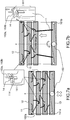
- a synchronized deployment means speed control device 16a or 16b which includes one or two secondary pulleys 161a, 161b attached to the upper platform 12 and to each connecting platform 15; the same cable or ribbon 162a, 162b connects the secondary pulleys of different platforms to the main pulley 160.
- This locking / release device shown Figures 7a and 7b in zoom comprises for each stage Ei a hook 163a, 163b linked to the upper platform 12 or to the upper connecting platform 15 of this stage Ei (except possibly the upper link platform of the stage E1, the deployment of this first stage being controlled by the release of the stacking system maintaining the structure in stored configuration during the launching phase, and then maintained and then regulated in speed by the main pulley according to whether it is stopped as symbolized by an X on the figures 7a and 7d , or running as symbolized by a rounded arrow on the figures 7b and 7c ).
- the other end of the hook is intended to be hooked during locking to the lower link platform of this stage Ei in the following manner.
- This other end has a "U” shape in the YZ plane of this lower platform, the branches of the "U” engaging in notches provided for this purpose in the upper end 111 of the link arm 11 (this end is in the form of a tape measure) itself attached to this lower platform.
- this end 111 is flattened and the branches of the "U” are engaged in the tape measure thus blocking its deployment: the lower platform is then hooked to its upper platform by the hook.
- the deployment of the connecting arm equipped with tape measures the deformation of these ends which resume their curvilinear shape (rest position).
- This locking-release device can also be installed on the mast independently of the other elements (pulleys, cables, etc.) of the speed regulation means.
- the mast can be used for example to move a device or an antenna from the body of a satellite.
- the lower platform 13 of the lower stage of the mast is fixed on the satellite box and the device to be removed is fixed to the upper platform 12 of the upper stage of the mast.
Claims (16)
- Ausfahrbarer Mast mit spontaner autonomer Ausfahrbewegung, der mindestens einen grundlegenden Strukturblock (10) mit einer Ausfahrlängsachse X aufweist, wobei der grundlegende Strukturblock zwei Plattformen, jeweils eine untere (13) und eine obere (12), die parallel zu einer Ebene YZ sind, die orthogonal zur Achse X verläuft, und N Stufen (E1,..., Ei, Ei+1,..., EN) aufweist, die parallel zur Ausfahrlängsachse X übereinander gestapelt sind, wobei N größer als 1 ist und wobei i zwischen 1 und N-1 liegt, wobei jede Stufe (Ei) mindestens sechs längliche, flexible Verbindungsarme (11) aufweist, die durch Maßbänder gelenkig verbunden sind, die sich in ausgefahrener Position in zur Achse X parallelen Ebenen befinden und in Bezug auf die Achse X geneigt sind, wobei die N Stufen untereinander jeweils paarweise mittels Verbindungsplattformen (15) befestigt sind, die parallel zur Ebene YZ verlaufen, wobei die beiden aneinander angrenzenden, jeweils oberen und unteren Stufen (Ei, Ei+1) in Bezug zueinander durch eine Drehung um die Ausfahrachse X winklig versetzt sind und Mittel zur Geschwindigkeitsregulierung des Ausfahrens des Masts aufweisen, die eine motorisierte Hauptlaufrolle (160) umfassen, die an der unteren Plattform (13) befestigt ist, und sekundäre, nicht motorisierte Laufrollen (161a, 161b), die fähig sind, durch die Hauptlaufrolle (160) mittels mindestens eines Kabels (162a, 162b) oder eines Bands angetrieben zu werden.
- Ausfahrbarer Mast nach dem vorhergehenden Anspruch, dadurch gekennzeichnet, dass mindestens eine sekundäre Laufrolle (161a, 161b) an der oberen Plattform (12) und an jeder Verbindungsplattform (15) befestigt ist, und dadurch, dass ein selbes Kabel (162a, 162b) oder Band die sekundären Laufrollen der verschiedenen Plattformen mit der Hauptlaufrolle (160) verbindet.
- Ausfahrbarer Mast nach Anspruch 1, dadurch gekennzeichnet, dass die sekundären Laufrollen (161a, 161b) an der unteren Plattform (13) befestigt sind, die Hauptlaufrolle (160) so viele Stufen wie sekundäre Laufrollen aufweist, und dadurch, dass die Mittel zur Geschwindigkeitsregulierung genauso viele Kabel (162a, 162b) oder Bänder wie sekundäre Laufrollen aufweisen, die jeweils an der oberen Plattform (12) und an jeder Verbindungsplattform (15) befestigt sind.
- Ausfahrbarer Mast nach Anspruch 1, dadurch gekennzeichnet, dass die sekundären Laufrollen (161a, 161b) an der unteren Plattform (13) befestigt sind, die Hauptlaufrolle (160) genauso viele Stufen wie sekundäre Laufrollen aufweist, und dadurch, dass die Mittel zur Geschwindigkeitsregulierung genauso viele Kabel (162a, 162b) oder Bänder wie Stufen der Hauptlaufrolle (160) und/oder mobile Plattformen (15) und die obere Plattform (12) aufweisen, wobei die Kabel oder Bänder an der oberen Plattform (12) befestigt sind.
- Ausfahrbarer Mast nach dem vorhergehenden Anspruch, dadurch gekennzeichnet, dass zwei aneinander angrenzende, jeweils untere und obere Stufen (Ei, Ei+1) untereinander durch eine Verbindungsplattform (15) befestigt sind, die den beiden aneinander angrenzenden Stufen (Ei, Ei+1) gemeinsam ist.
- Ausfahrbarer Mast nach einem der vorhergehenden Ansprüche, dadurch gekennzeichnet, dass jede obere Plattform (12), untere Plattform (13) und Verbindungsplattform (15) Befestigungslaschen (14) aufweist, die in regelmäßig verteilten Paaren gruppiert sind, wobei jede Befestigungslasche zur Befestigung eines Endes (111) eines Verbindungsarms dient.
- Ausfahrbarer Mast nach einem der vorhergehenden Ansprüche, dadurch gekennzeichnet, dass die Befestigungslaschen (14) zur Außenseite des Masts ausgerichtet sind, und dadurch, dass für jedes Paar von Befestigungslaschen die Verbindungsarme in gefalteter Konfiguration in einem Winkel zwischen 0° und 45° in der Ebene YZ tangential zur Plattform ausgerichtet sind.
- Ausfahrbarer Mast nach einem der vorhergehenden Ansprüche, dadurch gekennzeichnet, dass jedes Maßband (11) Faltzonen (112) mit Kreisbogenquerschnitt und Zonen ohne Faltung (113) mit Kreisbogenquerschnitt hat, und dadurch, dass der Kreisbogen der Zonen ohne Faltung länger als derjenige der Faltzonen ist.
- Ausfahrbarer Mast nach dem vorhergehenden Anspruch, dadurch gekennzeichnet, dass sich die Faltzonen (112) an den zwei Enden (111) des Verbindungsarms und in einer Zwischenzone befinden, und dadurch, dass die Kreisbogenquerschnitte der Zonen an den Enden diametral entgegengesetzt sind in Bezug auf den Querschnitt der Zwischenzone.
- Ausfahrbarer Mast nach Anspruch 8, dadurch gekennzeichnet, dass sich die Faltzonen (112) an den zwei Enden (111) und in einer Zwischenzone befinden und einen Kreisbogenquerschnitt haben, und dadurch, dass die Querschnitte der Zonen ohne Faltung (113) einen röhrenförmigen Querschnitt haben.
- Ausfahrbarer Mast nach einem der vorhergehenden Ansprüche, dadurch gekennzeichnet, dass die Verbindungsplattform (15) mindestens sechs Paare von Befestigungslaschen (14) aufweist.
- Ausfahrbarer Mast nach einem der vorhergehenden Ansprüche, dadurch gekennzeichnet, dass alle Befestigungsarme (11) identisch sind.
- Ausfahrbarer Mast nach einem der vorhergehenden Ansprüche, dadurch gekennzeichnet, dass er mehrere identische Strukturblöcke (10) aufweist, die übereinander gestapelt sind.
- Ausfahrbarer Mast nach einem der vorhergehenden Ansprüche, dadurch gekennzeichnet, dass eine Verriegelungs-Freigabe-Vorrichtung der Ausfahrbewegung (111, 114, 163a, 163b) auf jeder Verbindungsplattform (15) positioniert ist, um nach dem Ausfahren der Plattform die Freigabe der daran angrenzenden Plattform, die darüber liegt, zu gestatten.
- Ausfahrbarer Mast nach dem vorhergehenden Anspruch, dadurch gekennzeichnet, dass die Enden (111) der Verbindungsarme in Form von Maßbändern ein Profil haben, das je nach ausgefahrener oder gefalteter Position der Verbindungsarme unterschiedlich ist, und dadurch, dass die Verriegelungs-Freigabe-Vorrichtung Mittel zur Verrieglung-Freigabe in Abhängigkeit vom Profil aufweisen.
- Satellit, dadurch gekennzeichnet, dass er mindestens einen ausfahrbaren Mast mit spontaner autonomer Ausfahrbewegung nach einem der vorhergehenden Ansprüche aufweist.
Applications Claiming Priority (1)
| Application Number | Priority Date | Filing Date | Title |
|---|---|---|---|
| FR1401992A FR3025498B1 (fr) | 2014-09-05 | 2014-09-05 | Mat deployable a deploiement spontane autonome et satellite comportant au moins un tel mat |
Publications (2)
| Publication Number | Publication Date |
|---|---|
| EP2993131A1 EP2993131A1 (de) | 2016-03-09 |
| EP2993131B1 true EP2993131B1 (de) | 2017-03-29 |
Family
ID=52779675
Family Applications (1)
| Application Number | Title | Priority Date | Filing Date |
|---|---|---|---|
| EP15182588.2A Active EP2993131B1 (de) | 2014-09-05 | 2015-08-26 | Ausfahrbarer mast mit autonomer spontaner ausfahrbewegung, und satellit, der mit mindestens einem solchen mast ausgestattet ist |
Country Status (6)
| Country | Link |
|---|---|
| US (1) | US9764857B2 (de) |
| EP (1) | EP2993131B1 (de) |
| JP (1) | JP6623004B2 (de) |
| CA (1) | CA2902034C (de) |
| ES (1) | ES2628484T3 (de) |
| FR (1) | FR3025498B1 (de) |
Families Citing this family (11)
| Publication number | Priority date | Publication date | Assignee | Title |
|---|---|---|---|---|
| US10263316B2 (en) | 2013-09-06 | 2019-04-16 | MMA Design, LLC | Deployable reflectarray antenna structure |
| US9856039B2 (en) * | 2014-10-08 | 2018-01-02 | Analytical Mechanics Associates, Inc. | Extendable solar array for a spacecraft system |
| US10119292B1 (en) * | 2015-07-02 | 2018-11-06 | M.M.A. Design, LLC | Deployable boom and deployable boom with solar blanket |
| US10435182B1 (en) * | 2016-09-12 | 2019-10-08 | Space Systems/Loral, Llc | Articulation techniques for a spacecraft solar array |
| GB2555657A (en) * | 2016-11-08 | 2018-05-09 | Oxford Space Systems | Deployable mast structure |
| FR3087426B1 (fr) * | 2018-10-18 | 2022-03-11 | Thales Sa | Dispositif deployable a metre-ruban a section non constante |
| CN109616735B (zh) * | 2019-01-18 | 2023-09-22 | 燕山大学 | 基于剪式单元的太阳花形环形桁架可展开天线机构 |
| CN109616737B (zh) * | 2019-01-18 | 2023-12-01 | 燕山大学 | 单自由度剪铰联动式双环桁架可展开天线机构 |
| DE102019109810B4 (de) * | 2019-04-12 | 2023-01-19 | Deutsches Zentrum für Luft- und Raumfahrt e.V. | Vorrichtung und Verfahren zum Entfalten eines aufgerollten länglichen Hohlkörpers |
| CN110979742B (zh) * | 2019-11-29 | 2021-12-07 | 北京卫星制造厂有限公司 | 一种适用于空间环境的大展收比展开机构 |
| CN115817866B (zh) * | 2022-12-30 | 2023-07-11 | 中国科学院空间应用工程与技术中心 | 在线柜移动维修平台用旋转锁紧器、支撑件及维修平台 |
Family Cites Families (21)
| Publication number | Priority date | Publication date | Assignee | Title |
|---|---|---|---|---|
| US1360131A (en) * | 1916-03-28 | 1920-11-23 | Axel N Miller | Scaffold |
| US1511679A (en) * | 1922-06-23 | 1924-10-14 | Schwarz Carl | Extension tower |
| US2697845A (en) * | 1951-06-18 | 1954-12-28 | Paul E Broner | Link structure |
| US3593481A (en) * | 1969-03-19 | 1971-07-20 | Tom T Mikulin | Extensible structure |
| EP0408826B1 (de) * | 1989-07-19 | 1994-09-14 | Japan Aircraft Mfg. Co., Ltd | Ausziehbarer Mast |
| US5239793A (en) * | 1991-06-03 | 1993-08-31 | General Electric Company | Hinge element and deployable structures including hinge element |
| US5184444A (en) * | 1991-08-09 | 1993-02-09 | Aec-Able Engineering Co., Inc. | Survivable deployable/retractable mast |
| US5351062A (en) * | 1992-09-08 | 1994-09-27 | General Electric Company | Retractable distributed array antenna |
| US6374565B1 (en) * | 1999-11-09 | 2002-04-23 | Foster-Miller, Inc. | Foldable member |
| US6904722B2 (en) * | 2001-02-21 | 2005-06-14 | The United States Of America As Represented By The Secretary Of The Navy | Elongated truss boom structures for space applications |
| US7028442B2 (en) * | 2001-07-03 | 2006-04-18 | Merrifield Donald V | Deployable truss beam with orthogonally-hinged folding diagonals |
| JP4435579B2 (ja) * | 2004-01-05 | 2010-03-17 | 真一 中須賀 | 中空伸展ブーム |
| EP1676776B1 (de) * | 2004-12-28 | 2008-12-10 | Alcatel Lucent | Verbindungsvorrichtung für Elemente einer Raumfahrtausrüstung mit flexiblen ausbringbaren Blättern |
| US20070145195A1 (en) * | 2005-12-23 | 2007-06-28 | Northrop Grumman Space & Mission Systems Corporation | Deployable array support structure |
| US7617639B1 (en) * | 2006-08-08 | 2009-11-17 | The United States Of America As Represented By The Secretary Of The Air Force | Tape-spring deployable boom |
| US20080283670A1 (en) * | 2006-12-13 | 2008-11-20 | Thomas Jeffrey Harvey | K-truss deployable boom system |
| FR2933771B1 (fr) * | 2008-07-11 | 2010-08-13 | Thales Sa | Metre ruban a deploiement thermique et structure deployable comportant ledit metre ruban |
| EP2272761A1 (de) * | 2009-06-18 | 2011-01-12 | Astrium Limited | Ausziehbare Struktur |
| US8683755B1 (en) * | 2010-01-21 | 2014-04-01 | Deployable Space Systems, Inc. | Directionally controlled elastically deployable roll-out solar array |
| FR2974348B1 (fr) * | 2011-04-21 | 2014-01-24 | Thales Sa | Dispositif de protection d'un instrument optique d'un satellite |
| FR3003846B1 (fr) * | 2013-03-29 | 2017-01-27 | Thales Sa | Mat deployable a deploiement spontane autonome et satellite comportant au moins un tel mat |
-
2014
- 2014-09-05 FR FR1401992A patent/FR3025498B1/fr active Active
-
2015
- 2015-08-26 ES ES15182588.2T patent/ES2628484T3/es active Active
- 2015-08-26 EP EP15182588.2A patent/EP2993131B1/de active Active
- 2015-08-28 CA CA2902034A patent/CA2902034C/en active Active
- 2015-08-31 JP JP2015170065A patent/JP6623004B2/ja active Active
- 2015-09-04 US US14/846,242 patent/US9764857B2/en active Active
Non-Patent Citations (1)
| Title |
|---|
| None * |
Also Published As
| Publication number | Publication date |
|---|---|
| ES2628484T3 (es) | 2017-08-03 |
| US9764857B2 (en) | 2017-09-19 |
| CA2902034C (en) | 2023-03-14 |
| US20160068281A1 (en) | 2016-03-10 |
| FR3025498A1 (fr) | 2016-03-11 |
| JP6623004B2 (ja) | 2019-12-18 |
| CA2902034A1 (en) | 2016-03-05 |
| EP2993131A1 (de) | 2016-03-09 |
| FR3025498B1 (fr) | 2017-12-08 |
| JP2016056947A (ja) | 2016-04-21 |
Similar Documents
| Publication | Publication Date | Title |
|---|---|---|
| EP2993131B1 (de) | Ausfahrbarer mast mit autonomer spontaner ausfahrbewegung, und satellit, der mit mindestens einem solchen mast ausgestattet ist | |
| EP2783989B1 (de) | Ausfahrbarer Mast mit autonomer spontaner Ausfahrbewegung, und Satellit, der mit mindestens einem solchen Mast ausgestattet ist | |
| CA2834593C (fr) | Dispositif de deploiement et de reploiement d'une structure flexible, structure deployable flexible et satellite munis d'un tel dispositif | |
| EP2514674B1 (de) | Schutzvorrichtung für ein optisches Instrument eines Satelliten | |
| FR3024227A1 (fr) | Procede d'encastrement escamotable de metre-ruban pour une structure deployable et structure deployable a metre-ruban | |
| WO2006070156A1 (fr) | Dispositif de support d'elements d'un equipement spatial, a lames flexibles deployables | |
| FR2902763A1 (fr) | Articulation auto-motorisee pour ensemble articule tel qu'un panneau solaire de satellite | |
| EP3326920A1 (de) | Entfaltbare struktur mit spontaner entfaltung | |
| FR2778028A1 (fr) | Reflecteur et element de reflecteur pour des antennes d'application spatiales ainsi que procede pour deployer un reflecteur | |
| EP3732096A1 (de) | Entfaltbare unterwasservorrichtung | |
| CA2982070C (fr) | Faisceau torsible pour pale, un ensemble de faisceaux torsibles, un rotor et un aeronef | |
| EP2724943B1 (de) | Motorisierungssystem mit angepasstem drehmoment für ein gelenk mit gekreuzten aufrollmitteln | |
| EP2724944A2 (de) | Motorisierungssystem für Gelenk mit gekreuzten Aufrollmitteln mit zuverlässigem Rollverhalten | |
| EP2307277B1 (de) | Ausbringbarer mast mit einer selbstausbringbaren klappstruktur, der im ausgebrachten zustand starr ist | |
| EP2520494B1 (de) | Vorrichtung zum Schutz eines optischen Vielfachspiegelinstruments | |
| EP2461065B1 (de) | Gelenkeinrichtung mit einem Strängbündel aus Formgedächtnismaterial | |
| EP0239454B1 (de) | Bewegungsmechanismus für ein Teil und seine Bestimmung für einen entfaltbaren Solarzellengenerator | |
| FR2589982A1 (fr) | Structure pliable, notamment pour l'espace | |
| FR2973346A1 (fr) | Structure pliable/deployable a deploiement spontane et verrouillage spontane a l'etat deploye | |
| WO2021009072A1 (fr) | Structure pliable/déployable comportant un mât déployable | |
| FR3061246A1 (fr) | Dispositif de cerclage | |
| FR2655720A1 (fr) | Aile galbee deployable pour engin volant. | |
| WO2010004169A2 (fr) | Mât déployable à ossature repliée déployable se verrouillant par construction à l'état déployé | |
| FR2717207A1 (fr) | Mât porteur du type enroulable en matériau composite et son dispositif de mise en Óoeuvre. |
Legal Events
| Date | Code | Title | Description |
|---|---|---|---|
| PUAI | Public reference made under article 153(3) epc to a published international application that has entered the european phase |
Free format text: ORIGINAL CODE: 0009012 |
|
| AK | Designated contracting states |
Kind code of ref document: A1 Designated state(s): AL AT BE BG CH CY CZ DE DK EE ES FI FR GB GR HR HU IE IS IT LI LT LU LV MC MK MT NL NO PL PT RO RS SE SI SK SM TR |
|
| AX | Request for extension of the european patent |
Extension state: BA ME |
|
| 17P | Request for examination filed |
Effective date: 20160826 |
|
| RBV | Designated contracting states (corrected) |
Designated state(s): AL AT BE BG CH CY CZ DE DK EE ES FI FR GB GR HR HU IE IS IT LI LT LU LV MC MK MT NL NO PL PT RO RS SE SI SK SM TR |
|
| GRAP | Despatch of communication of intention to grant a patent |
Free format text: ORIGINAL CODE: EPIDOSNIGR1 |
|
| RIC1 | Information provided on ipc code assigned before grant |
Ipc: H01Q 1/12 20060101ALI20160916BHEP Ipc: B64G 1/22 20060101AFI20160916BHEP Ipc: F16M 11/38 20060101ALI20160916BHEP |
|
| INTG | Intention to grant announced |
Effective date: 20161025 |
|
| GRAS | Grant fee paid |
Free format text: ORIGINAL CODE: EPIDOSNIGR3 |
|
| GRAA | (expected) grant |
Free format text: ORIGINAL CODE: 0009210 |
|
| AK | Designated contracting states |
Kind code of ref document: B1 Designated state(s): AL AT BE BG CH CY CZ DE DK EE ES FI FR GB GR HR HU IE IS IT LI LT LU LV MC MK MT NL NO PL PT RO RS SE SI SK SM TR |
|
| REG | Reference to a national code |
Ref country code: GB Ref legal event code: FG4D Free format text: NOT ENGLISH |
|
| REG | Reference to a national code |
Ref country code: CH Ref legal event code: EP |
|
| REG | Reference to a national code |
Ref country code: AT Ref legal event code: REF Ref document number: 879508 Country of ref document: AT Kind code of ref document: T Effective date: 20170415 |
|
| REG | Reference to a national code |
Ref country code: IE Ref legal event code: FG4D Free format text: LANGUAGE OF EP DOCUMENT: FRENCH |
|
| REG | Reference to a national code |
Ref country code: CH Ref legal event code: NV Representative=s name: SERVOPATENT GMBH, CH |
|
| REG | Reference to a national code |
Ref country code: DE Ref legal event code: R096 Ref document number: 602015002011 Country of ref document: DE |
|
| REG | Reference to a national code |
Ref country code: NL Ref legal event code: FP |
|
| REG | Reference to a national code |
Ref country code: FR Ref legal event code: PLFP Year of fee payment: 3 |
|
| PG25 | Lapsed in a contracting state [announced via postgrant information from national office to epo] |
Ref country code: NO Free format text: LAPSE BECAUSE OF FAILURE TO SUBMIT A TRANSLATION OF THE DESCRIPTION OR TO PAY THE FEE WITHIN THE PRESCRIBED TIME-LIMIT Effective date: 20170629 Ref country code: LT Free format text: LAPSE BECAUSE OF FAILURE TO SUBMIT A TRANSLATION OF THE DESCRIPTION OR TO PAY THE FEE WITHIN THE PRESCRIBED TIME-LIMIT Effective date: 20170329 Ref country code: HR Free format text: LAPSE BECAUSE OF FAILURE TO SUBMIT A TRANSLATION OF THE DESCRIPTION OR TO PAY THE FEE WITHIN THE PRESCRIBED TIME-LIMIT Effective date: 20170329 Ref country code: GR Free format text: LAPSE BECAUSE OF FAILURE TO SUBMIT A TRANSLATION OF THE DESCRIPTION OR TO PAY THE FEE WITHIN THE PRESCRIBED TIME-LIMIT Effective date: 20170630 Ref country code: FI Free format text: LAPSE BECAUSE OF FAILURE TO SUBMIT A TRANSLATION OF THE DESCRIPTION OR TO PAY THE FEE WITHIN THE PRESCRIBED TIME-LIMIT Effective date: 20170329 |
|
| REG | Reference to a national code |
Ref country code: ES Ref legal event code: FG2A Ref document number: 2628484 Country of ref document: ES Kind code of ref document: T3 Effective date: 20170803 |
|
| REG | Reference to a national code |
Ref country code: AT Ref legal event code: MK05 Ref document number: 879508 Country of ref document: AT Kind code of ref document: T Effective date: 20170329 |
|
| PG25 | Lapsed in a contracting state [announced via postgrant information from national office to epo] |
Ref country code: BG Free format text: LAPSE BECAUSE OF FAILURE TO SUBMIT A TRANSLATION OF THE DESCRIPTION OR TO PAY THE FEE WITHIN THE PRESCRIBED TIME-LIMIT Effective date: 20170629 Ref country code: SE Free format text: LAPSE BECAUSE OF FAILURE TO SUBMIT A TRANSLATION OF THE DESCRIPTION OR TO PAY THE FEE WITHIN THE PRESCRIBED TIME-LIMIT Effective date: 20170329 Ref country code: LV Free format text: LAPSE BECAUSE OF FAILURE TO SUBMIT A TRANSLATION OF THE DESCRIPTION OR TO PAY THE FEE WITHIN THE PRESCRIBED TIME-LIMIT Effective date: 20170329 Ref country code: RS Free format text: LAPSE BECAUSE OF FAILURE TO SUBMIT A TRANSLATION OF THE DESCRIPTION OR TO PAY THE FEE WITHIN THE PRESCRIBED TIME-LIMIT Effective date: 20170329 |
|
| PG25 | Lapsed in a contracting state [announced via postgrant information from national office to epo] |
Ref country code: SK Free format text: LAPSE BECAUSE OF FAILURE TO SUBMIT A TRANSLATION OF THE DESCRIPTION OR TO PAY THE FEE WITHIN THE PRESCRIBED TIME-LIMIT Effective date: 20170329 Ref country code: RO Free format text: LAPSE BECAUSE OF FAILURE TO SUBMIT A TRANSLATION OF THE DESCRIPTION OR TO PAY THE FEE WITHIN THE PRESCRIBED TIME-LIMIT Effective date: 20170329 Ref country code: CZ Free format text: LAPSE BECAUSE OF FAILURE TO SUBMIT A TRANSLATION OF THE DESCRIPTION OR TO PAY THE FEE WITHIN THE PRESCRIBED TIME-LIMIT Effective date: 20170329 Ref country code: EE Free format text: LAPSE BECAUSE OF FAILURE TO SUBMIT A TRANSLATION OF THE DESCRIPTION OR TO PAY THE FEE WITHIN THE PRESCRIBED TIME-LIMIT Effective date: 20170329 Ref country code: AT Free format text: LAPSE BECAUSE OF FAILURE TO SUBMIT A TRANSLATION OF THE DESCRIPTION OR TO PAY THE FEE WITHIN THE PRESCRIBED TIME-LIMIT Effective date: 20170329 |
|
| PG25 | Lapsed in a contracting state [announced via postgrant information from national office to epo] |
Ref country code: PL Free format text: LAPSE BECAUSE OF FAILURE TO SUBMIT A TRANSLATION OF THE DESCRIPTION OR TO PAY THE FEE WITHIN THE PRESCRIBED TIME-LIMIT Effective date: 20170329 Ref country code: SM Free format text: LAPSE BECAUSE OF FAILURE TO SUBMIT A TRANSLATION OF THE DESCRIPTION OR TO PAY THE FEE WITHIN THE PRESCRIBED TIME-LIMIT Effective date: 20170329 Ref country code: IS Free format text: LAPSE BECAUSE OF FAILURE TO SUBMIT A TRANSLATION OF THE DESCRIPTION OR TO PAY THE FEE WITHIN THE PRESCRIBED TIME-LIMIT Effective date: 20170729 |
|
| REG | Reference to a national code |
Ref country code: DE Ref legal event code: R097 Ref document number: 602015002011 Country of ref document: DE |
|
| PG25 | Lapsed in a contracting state [announced via postgrant information from national office to epo] |
Ref country code: DK Free format text: LAPSE BECAUSE OF FAILURE TO SUBMIT A TRANSLATION OF THE DESCRIPTION OR TO PAY THE FEE WITHIN THE PRESCRIBED TIME-LIMIT Effective date: 20170329 |
|
| PLBE | No opposition filed within time limit |
Free format text: ORIGINAL CODE: 0009261 |
|
| STAA | Information on the status of an ep patent application or granted ep patent |
Free format text: STATUS: NO OPPOSITION FILED WITHIN TIME LIMIT |
|
| 26N | No opposition filed |
Effective date: 20180103 |
|
| PG25 | Lapsed in a contracting state [announced via postgrant information from national office to epo] |
Ref country code: MC Free format text: LAPSE BECAUSE OF FAILURE TO SUBMIT A TRANSLATION OF THE DESCRIPTION OR TO PAY THE FEE WITHIN THE PRESCRIBED TIME-LIMIT Effective date: 20170329 |
|
| REG | Reference to a national code |
Ref country code: BE Ref legal event code: MM Effective date: 20170831 |
|
| REG | Reference to a national code |
Ref country code: IE Ref legal event code: MM4A |
|
| PG25 | Lapsed in a contracting state [announced via postgrant information from national office to epo] |
Ref country code: SI Free format text: LAPSE BECAUSE OF FAILURE TO SUBMIT A TRANSLATION OF THE DESCRIPTION OR TO PAY THE FEE WITHIN THE PRESCRIBED TIME-LIMIT Effective date: 20170329 |
|
| PG25 | Lapsed in a contracting state [announced via postgrant information from national office to epo] |
Ref country code: LU Free format text: LAPSE BECAUSE OF NON-PAYMENT OF DUE FEES Effective date: 20170826 |
|
| REG | Reference to a national code |
Ref country code: FR Ref legal event code: PLFP Year of fee payment: 4 |
|
| PG25 | Lapsed in a contracting state [announced via postgrant information from national office to epo] |
Ref country code: IE Free format text: LAPSE BECAUSE OF NON-PAYMENT OF DUE FEES Effective date: 20170826 |
|
| PG25 | Lapsed in a contracting state [announced via postgrant information from national office to epo] |
Ref country code: BE Free format text: LAPSE BECAUSE OF NON-PAYMENT OF DUE FEES Effective date: 20170831 |
|
| PG25 | Lapsed in a contracting state [announced via postgrant information from national office to epo] |
Ref country code: MT Free format text: LAPSE BECAUSE OF FAILURE TO SUBMIT A TRANSLATION OF THE DESCRIPTION OR TO PAY THE FEE WITHIN THE PRESCRIBED TIME-LIMIT Effective date: 20170329 |
|
| PG25 | Lapsed in a contracting state [announced via postgrant information from national office to epo] |
Ref country code: HU Free format text: LAPSE BECAUSE OF FAILURE TO SUBMIT A TRANSLATION OF THE DESCRIPTION OR TO PAY THE FEE WITHIN THE PRESCRIBED TIME-LIMIT; INVALID AB INITIO Effective date: 20150826 |
|
| PG25 | Lapsed in a contracting state [announced via postgrant information from national office to epo] |
Ref country code: CY Free format text: LAPSE BECAUSE OF FAILURE TO SUBMIT A TRANSLATION OF THE DESCRIPTION OR TO PAY THE FEE WITHIN THE PRESCRIBED TIME-LIMIT Effective date: 20170329 |
|
| PG25 | Lapsed in a contracting state [announced via postgrant information from national office to epo] |
Ref country code: MK Free format text: LAPSE BECAUSE OF FAILURE TO SUBMIT A TRANSLATION OF THE DESCRIPTION OR TO PAY THE FEE WITHIN THE PRESCRIBED TIME-LIMIT Effective date: 20170329 |
|
| PG25 | Lapsed in a contracting state [announced via postgrant information from national office to epo] |
Ref country code: TR Free format text: LAPSE BECAUSE OF FAILURE TO SUBMIT A TRANSLATION OF THE DESCRIPTION OR TO PAY THE FEE WITHIN THE PRESCRIBED TIME-LIMIT Effective date: 20170329 |
|
| PG25 | Lapsed in a contracting state [announced via postgrant information from national office to epo] |
Ref country code: PT Free format text: LAPSE BECAUSE OF FAILURE TO SUBMIT A TRANSLATION OF THE DESCRIPTION OR TO PAY THE FEE WITHIN THE PRESCRIBED TIME-LIMIT Effective date: 20170329 |
|
| REG | Reference to a national code |
Ref country code: CH Ref legal event code: PCAR Free format text: NEW ADDRESS: WANNERSTRASSE 9/1, 8045 ZUERICH (CH) |
|
| PG25 | Lapsed in a contracting state [announced via postgrant information from national office to epo] |
Ref country code: AL Free format text: LAPSE BECAUSE OF FAILURE TO SUBMIT A TRANSLATION OF THE DESCRIPTION OR TO PAY THE FEE WITHIN THE PRESCRIBED TIME-LIMIT Effective date: 20170329 |
|
| PGFP | Annual fee paid to national office [announced via postgrant information from national office to epo] |
Ref country code: NL Payment date: 20230728 Year of fee payment: 9 |
|
| PGFP | Annual fee paid to national office [announced via postgrant information from national office to epo] |
Ref country code: IT Payment date: 20230726 Year of fee payment: 9 Ref country code: GB Payment date: 20230713 Year of fee payment: 9 Ref country code: ES Payment date: 20230905 Year of fee payment: 9 Ref country code: CH Payment date: 20230902 Year of fee payment: 9 |
|
| PGFP | Annual fee paid to national office [announced via postgrant information from national office to epo] |
Ref country code: FR Payment date: 20230721 Year of fee payment: 9 Ref country code: DE Payment date: 20230718 Year of fee payment: 9 |