EP2992848B1 - Device for contact coagulation of biological tissue - Google Patents
Device for contact coagulation of biological tissue Download PDFInfo
- Publication number
- EP2992848B1 EP2992848B1 EP14183771.6A EP14183771A EP2992848B1 EP 2992848 B1 EP2992848 B1 EP 2992848B1 EP 14183771 A EP14183771 A EP 14183771A EP 2992848 B1 EP2992848 B1 EP 2992848B1
- Authority
- EP
- European Patent Office
- Prior art keywords
- voltage
- tissue
- app
- tissue impedance
- value
- Prior art date
- Legal status (The legal status is an assumption and is not a legal conclusion. Google has not performed a legal analysis and makes no representation as to the accuracy of the status listed.)
- Active
Links
- 230000015271 coagulation Effects 0.000 title claims description 44
- 238000005345 coagulation Methods 0.000 title claims description 43
- 238000000034 method Methods 0.000 claims description 17
- 230000015572 biosynthetic process Effects 0.000 claims description 11
- 230000008569 process Effects 0.000 claims description 11
- 238000001514 detection method Methods 0.000 claims description 7
- 238000004393 prognosis Methods 0.000 claims description 6
- 230000010355 oscillation Effects 0.000 claims description 3
- 230000004044 response Effects 0.000 claims description 3
- 238000012544 monitoring process Methods 0.000 claims description 2
- 238000005070 sampling Methods 0.000 claims description 2
- 210000001519 tissue Anatomy 0.000 description 115
- 238000005259 measurement Methods 0.000 description 12
- 239000012530 fluid Substances 0.000 description 6
- 238000009835 boiling Methods 0.000 description 5
- 238000010586 diagram Methods 0.000 description 4
- 238000003763 carbonization Methods 0.000 description 3
- 230000000694 effects Effects 0.000 description 3
- 230000007935 neutral effect Effects 0.000 description 3
- 230000000712 assembly Effects 0.000 description 2
- 238000000429 assembly Methods 0.000 description 2
- 230000000740 bleeding effect Effects 0.000 description 2
- 230000009172 bursting Effects 0.000 description 2
- 238000004364 calculation method Methods 0.000 description 2
- 230000015556 catabolic process Effects 0.000 description 2
- 239000002800 charge carrier Substances 0.000 description 2
- 238000011109 contamination Methods 0.000 description 2
- 230000007423 decrease Effects 0.000 description 2
- 238000001035 drying Methods 0.000 description 2
- 239000000523 sample Substances 0.000 description 2
- 206010052428 Wound Diseases 0.000 description 1
- 230000004913 activation Effects 0.000 description 1
- 230000003321 amplification Effects 0.000 description 1
- 210000004204 blood vessel Anatomy 0.000 description 1
- 210000000170 cell membrane Anatomy 0.000 description 1
- 238000004925 denaturation Methods 0.000 description 1
- 230000036425 denaturation Effects 0.000 description 1
- 230000001419 dependent effect Effects 0.000 description 1
- 238000001704 evaporation Methods 0.000 description 1
- 230000008020 evaporation Effects 0.000 description 1
- 210000003722 extracellular fluid Anatomy 0.000 description 1
- 239000004744 fabric Substances 0.000 description 1
- 230000006870 function Effects 0.000 description 1
- 230000004927 fusion Effects 0.000 description 1
- 238000010438 heat treatment Methods 0.000 description 1
- 208000015181 infectious disease Diseases 0.000 description 1
- 210000001365 lymphatic vessel Anatomy 0.000 description 1
- 230000004048 modification Effects 0.000 description 1
- 238000012986 modification Methods 0.000 description 1
- 238000003199 nucleic acid amplification method Methods 0.000 description 1
- 230000001717 pathogenic effect Effects 0.000 description 1
- 238000012545 processing Methods 0.000 description 1
- 102000004169 proteins and genes Human genes 0.000 description 1
- 108090000623 proteins and genes Proteins 0.000 description 1
- 230000029663 wound healing Effects 0.000 description 1
Images

Classifications
-
- A—HUMAN NECESSITIES
- A61—MEDICAL OR VETERINARY SCIENCE; HYGIENE
- A61B—DIAGNOSIS; SURGERY; IDENTIFICATION
- A61B18/00—Surgical instruments, devices or methods for transferring non-mechanical forms of energy to or from the body
- A61B18/04—Surgical instruments, devices or methods for transferring non-mechanical forms of energy to or from the body by heating
- A61B18/12—Surgical instruments, devices or methods for transferring non-mechanical forms of energy to or from the body by heating by passing a current through the tissue to be heated, e.g. high-frequency current
- A61B18/1206—Generators therefor
- A61B18/1233—Generators therefor with circuits for assuring patient safety
-
- A—HUMAN NECESSITIES
- A61—MEDICAL OR VETERINARY SCIENCE; HYGIENE
- A61B—DIAGNOSIS; SURGERY; IDENTIFICATION
- A61B18/00—Surgical instruments, devices or methods for transferring non-mechanical forms of energy to or from the body
- A61B18/04—Surgical instruments, devices or methods for transferring non-mechanical forms of energy to or from the body by heating
- A61B18/12—Surgical instruments, devices or methods for transferring non-mechanical forms of energy to or from the body by heating by passing a current through the tissue to be heated, e.g. high-frequency current
- A61B18/14—Probes or electrodes therefor
-
- A—HUMAN NECESSITIES
- A61—MEDICAL OR VETERINARY SCIENCE; HYGIENE
- A61B—DIAGNOSIS; SURGERY; IDENTIFICATION
- A61B18/00—Surgical instruments, devices or methods for transferring non-mechanical forms of energy to or from the body
- A61B2018/00571—Surgical instruments, devices or methods for transferring non-mechanical forms of energy to or from the body for achieving a particular surgical effect
- A61B2018/00589—Coagulation
-
- A—HUMAN NECESSITIES
- A61—MEDICAL OR VETERINARY SCIENCE; HYGIENE
- A61B—DIAGNOSIS; SURGERY; IDENTIFICATION
- A61B18/00—Surgical instruments, devices or methods for transferring non-mechanical forms of energy to or from the body
- A61B2018/00636—Sensing and controlling the application of energy
- A61B2018/00642—Sensing and controlling the application of energy with feedback, i.e. closed loop control
-
- A—HUMAN NECESSITIES
- A61—MEDICAL OR VETERINARY SCIENCE; HYGIENE
- A61B—DIAGNOSIS; SURGERY; IDENTIFICATION
- A61B18/00—Surgical instruments, devices or methods for transferring non-mechanical forms of energy to or from the body
- A61B2018/00636—Sensing and controlling the application of energy
- A61B2018/00666—Sensing and controlling the application of energy using a threshold value
- A61B2018/00672—Sensing and controlling the application of energy using a threshold value lower
-
- A—HUMAN NECESSITIES
- A61—MEDICAL OR VETERINARY SCIENCE; HYGIENE
- A61B—DIAGNOSIS; SURGERY; IDENTIFICATION
- A61B18/00—Surgical instruments, devices or methods for transferring non-mechanical forms of energy to or from the body
- A61B2018/00636—Sensing and controlling the application of energy
- A61B2018/00666—Sensing and controlling the application of energy using a threshold value
- A61B2018/00678—Sensing and controlling the application of energy using a threshold value upper
-
- A—HUMAN NECESSITIES
- A61—MEDICAL OR VETERINARY SCIENCE; HYGIENE
- A61B—DIAGNOSIS; SURGERY; IDENTIFICATION
- A61B18/00—Surgical instruments, devices or methods for transferring non-mechanical forms of energy to or from the body
- A61B2018/00636—Sensing and controlling the application of energy
- A61B2018/00696—Controlled or regulated parameters
- A61B2018/00767—Voltage
-
- A—HUMAN NECESSITIES
- A61—MEDICAL OR VETERINARY SCIENCE; HYGIENE
- A61B—DIAGNOSIS; SURGERY; IDENTIFICATION
- A61B18/00—Surgical instruments, devices or methods for transferring non-mechanical forms of energy to or from the body
- A61B2018/00636—Sensing and controlling the application of energy
- A61B2018/00773—Sensed parameters
- A61B2018/00827—Current
-
- A—HUMAN NECESSITIES
- A61—MEDICAL OR VETERINARY SCIENCE; HYGIENE
- A61B—DIAGNOSIS; SURGERY; IDENTIFICATION
- A61B18/00—Surgical instruments, devices or methods for transferring non-mechanical forms of energy to or from the body
- A61B2018/00636—Sensing and controlling the application of energy
- A61B2018/00773—Sensed parameters
- A61B2018/00869—Phase
-
- A—HUMAN NECESSITIES
- A61—MEDICAL OR VETERINARY SCIENCE; HYGIENE
- A61B—DIAGNOSIS; SURGERY; IDENTIFICATION
- A61B18/00—Surgical instruments, devices or methods for transferring non-mechanical forms of energy to or from the body
- A61B2018/00636—Sensing and controlling the application of energy
- A61B2018/00773—Sensed parameters
- A61B2018/00875—Resistance or impedance
-
- A—HUMAN NECESSITIES
- A61—MEDICAL OR VETERINARY SCIENCE; HYGIENE
- A61B—DIAGNOSIS; SURGERY; IDENTIFICATION
- A61B18/00—Surgical instruments, devices or methods for transferring non-mechanical forms of energy to or from the body
- A61B2018/00988—Means for storing information, e.g. calibration constants, or for preventing excessive use, e.g. usage, service life counter
Definitions
- the invention relates to a device for contact coagulation of biological tissue under the influence of electric current.
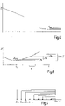
- phase I the tissue impedance Z decreases continuously. After some time, the boiling temperature of the tissue fluid is reached, causing the tissue resistance to rise again, which is referred to as "phase II". Usually the tissue impedance reaches Z in phase II values that are well above the minimum impedance of the tissue and often the initial impedance from phase I.
- a device and a method for the coagulation of tissue are known, in which the tissue impedance Z is queried and monitored. By continually adjusting the electrical energy delivered to the tissue, the impedance of the tissue follows a desired predetermined curve. This applies in particular to phase II.
- a coagulation device with monitoring of the tissue impedance is also known.
- the voltage applied to the tissue is gradually increased as the tissue impedance falls and passes through a minimum. Thereafter, when the tissue impedance reaches a certain value, the applied voltage is pulsed.
- the RU 2 294 171 C2 With increasing voltage during the fall of the tissue impedance and the passage through an impedance minimum, the RU 2 294 171 C2 .
- a high-frequency generator with automatic power control for high-frequency coagulation which has an arc indicator device for detecting an arc existing between the coagulation probe and the tissue.
- work is initially carried out with maximum output power. After the arc has been ignited, the maximum power continues to be delivered for a certain period of time. The output power is then reduced to zero for a predetermined second period of time. As long as the generator is activated, these cycles are repeated over and over again.
- a coagulation mode is achieved in which the coagulation initially begins with contact coagulation, after reaching the boiling point of the tissue fluid, an arc breaks through the vapor that forms, the current density at the point of breakdown at the arc being greatly increased, as a result of which a pronounced local coagulation effect occurs and the tissue becomes highly resistive.
- the arc ignites and jumps to different points until the entire tissue in the vicinity of the coagulation probe has become highly resistive, i.e. has been coagulated.
- Temporarily turning off the arc by setting the output power to zero prevents overburning, ie, over-carbonization of the tissue.
- tissue can stick to the instrument and, as a result, the instrument and the treatment personnel can be soiled, in some cases not inconsiderably so.
- the carbonization that occurs can complicate the wound healing process.
- an acoustically audible and visually perceptible tearing of the treated tissue can occur. This is caused by local tearing of tissue due to boiling tissue fluid and the associated increase in tissue pressure. The tearing of the tissue can cause previously stopped bleeding to start bleeding again.
- treated pathogenic tissue can spread to healthy tissue areas due to the tearing or can also be ingested by treatment personnel.
- the object of the invention is to specify a concept with which rapid tissue coagulation can be achieved with gentle treatment.
- tissue impedance Z In the impedance minimum, the tissue has reached its most conductive state. This occurs before the tissue fluid reaches its boiling point, ie before a temperature of 100°C is reached. When the HF voltage is applied, the tissue fluid then evaporates. Such evaporation leads to tissue pressure build-up and rupture and is avoided in the invention. This also avoids scattering of contaminated tissue, contamination of open wounds and instruments, and contamination or infection of surgical staff. In addition, tearing of already coagulated blood vessels, lymphatic vessels or other vessels is avoided. By continuing the coagulation with reduced tension, the coagulation can be continued without such effects until the desired tissue effect develops.
- the proposed new contact coagulation mode works with increased power input until the impedance minimum is reached.
- phase I the maximum possible HF energy is applied to the tissue by delivering a high HF voltage until the impedance minimum is reached.
- the coagulation begins when the instrument touches the tissue with the maximum power output of the generator, ie with an HF voltage which is preferably well above 200V, independently of the current.
- HF voltage which is preferably well above 200V
- a setting value for the voltage to be applied is stored in the generator control.
- the generator control is then set up to prompt the generator at the beginning of a coagulation program to provide the voltage to be applied at a value that is greater than the set value.
- the voltage to be applied at the beginning of a coagulation process is at least twice the set value. If the user sets the usual voltage suitable for contact coagulation (e.g. 200 V), he works with the system according to the invention at the beginning of a coagulation process with a voltage of at least 400 V.
- sparking does not occur because the voltage is reduced as soon as an impedance minimum has passed and vapor formation is imminent. By avoiding the formation of steam, the formation of sparks, the associated bursting of steam bubbles in the tissue and the associated disadvantages can also be avoided.
- the generator is prompted to provide the voltage to be applied with a value that is not greater than the set value.
- the setting value is set to a value that enables continued coagulation without sparking.
- the generator controller is preferably set up to cause the generator to react to the detection of a second or further minimum of the tissue impedance Z Reduce voltage to a value smaller than the setting value.
- this value is a predetermined percentage, for example 10%, lower than the previously supplied voltage.
- the generator controller can be set up to end the HF application of the generator when the voltage to be applied has reached a value that does not exceed or falls below a specified fraction of the set value.
- This fixed fraction can be, for example, 60% of the set voltage.
- the setting value of the voltage to be applied can be specified in steps or in an infinitely variable manner. Appropriate setting means are preferably provided for this purpose on the device feeding the instrument.
- the tissue impedance can be monitored continuously or in a quasi-continuous manner at points in time that follow one another in close succession.
- the time intervals between individual measurements of the tissue resistance are preferably less than 0.2 ms.
- the time intervals are preferably about 100 ps. This allows you to react very quickly to the changing tissue resistance.
- the applied voltage and the current flowing through the biological tissue, as well as their phase relationship to one another are preferably detected in time windows whose length is at least as long as one oscillation period, more preferably at least as long as several oscillation periods the HF voltage.
- at least one characteristic value of the applied Voltage and at least one characteristic of the flowing current detected may be the peak-to-peak voltage (double peak voltage), the crest voltage (single peak voltage), the average value of the voltage, the rectified value, the effective value, or the like. The same applies to the flowing current.
- a characteristic value of the current may be the peak-to-peak current (double peak current), the peak current (single peak current), the mean value of the magnitude of the current, the rectified value, the effective value, or the like.
- a parameter for the phase position can be the phase angle ⁇ between the two parameters mentioned, which describes the shift of the two parameters relative to one another.
- the tissue impedance Z can be taken as the quotient of a characteristic value of the voltage and a characteristic value of the current with reference to the phase position. In an advantageous embodiment, this quotient is compared with one or more previously determined quotients in order to recognize that a tissue resistance minimum has been reached and passed through.
- the minimum detector is set up to signal the tissue impedance minimum to the generator control.
- the minimum detector may be configured to detect the trend in tissue impedance based on measured tissue impedances in order to make a prognosis for the next tissue impedance to be measured, with reaching and passing through a tissue impedance minimum being signaled when the next measured tissue impedance Z is a predetermined value above the prognosis for the next tissue impedance to be measured. In this way, reaching the tissue impedance minimum can be detected before it rises again, and the formation of vapor bubbles can be suppressed even more quickly.
- FIG 1 Figure 10 illustrates an apparatus 10 for contact coagulation of biological tissue, which includes an instrument 11 and a powered device 12 .
- the instrument 11 and a neutral electrode 13 used to return current are each connected to the device 12 via cables 14, 15.
- Biological tissue 16 which is to be coagulated in sections by means of the instrument 11 and which closes the circuit between the instrument 11 and the neutral electrode 13, is in figure 1 symbolically indicated by a dashed block.
- the biological tissue 16 has a tissue impedance Z, which has an ohmic component R and more or less large reactive components jX, in particular a capacitive component.
- R Z ⁇ cos ⁇
- X Z ⁇ sin ⁇
- the device 12 contains a generator 17 for generating high-frequency electrical voltages and currents.
- the generator 17 is connected to an operating voltage that is provided by a power pack 18 .
- the operation of the generator 17 is determined by a generator control 19 which controls, for example, an electronic switching or amplification element 20 in order to excite an oscillating circuit belonging to the generator 17 .
- the generator control 19 can have one or more operating elements 21, by means of which specifications for the operation of the generator can be made and settings can be made by a user.
- the variables to be preset can include a setting value U Ein , with which the user sets voltage values for contact coagulation that he is familiar with (for example 200 V).
- the operating mode or other parameters include, for example, the desired coagulation volume or the desired coagulation time, the maximum energy to be applied or the like. Other parameters such as crest factor, maximum current, maximum power and the like can also be set.
- the generator 17 provides a voltage U App which is available at the electrode 22 of the instrument 11 and on the basis of which a current I App through the tissue 16 results.
- the voltage U App applied to the tissue and the current I App flowing through the tissue are recorded by a measuring device 23 and measured values are derived therefrom.
- the measuring device 23 determines the current tissue impedance Z from the measured value of the current I App and the measured value of the voltage U App .
- a minimum detector 24 is provided to detect whether or that the tissue impedance Z has reached or passed through an impedance minimum. In such a case, the minimum detector 24 signals this to the generator control 19.
- the generator control 19, the measuring device 23 and the minimum detector 24 are function blocks. They can be structurally integrated into a single assembly or divided into several individual assemblies. In particular, the measuring device 23 and the minimum detector 24 can be combined with the generator controller to form one assembly.
- the assemblies can be physical modules or also program modules or the like.
- the measuring device 23 can convert both the current I App to be measured and the voltage U App to be measured into data pairs using an analog/digital converter and then using a calculation block to determine the associated tissue impedance values.
- the tissue impedance values can be kept ready in a memory for further processing, for example.
- the minimum detector 24 can then be formed by a program routine which searches for an impedance minimum in the data pairs.
- the tissue impedance can be defined as the quotient of one of the characteristic values of the respectively measured voltage U App and one of the characteristic values of the measured current I App .
- figure 3 illustrates the measurement of the voltage U App .
- the voltage U App and the current I App ie at least one characteristic value in each case
- a time window t m is provided for this, which is somewhat shorter than the time interval ⁇ t.
- At least one suitable voltage value for example the peak value U p , the double peak value U pp , the mean value of the absolute value of the voltage Umean, the effective value Urms or a similar characteristic value for the voltage, is measured during the time window tm.
- a characteristic value for the current is measured accordingly. This can in turn be the peak current value I p , the average current value I mean or the effective current I rms .
- a characteristic value for the phase position is also measured. This can be the shift angle ⁇ between the voltage and the current.
- the tissue impedance is the quotient of one of the measured characteristic values for the voltage U App (e.g.
- U p , U pp , U mean or I rms a characteristic value for the current I App (e.g. I p , I pp , I mean or I rms ) with reference to the phasing of the measured characteristic values for the voltage and the current.
- the generator controller 19 is set up to use the measured or calculated values for the tissue impedance Z to specify different generator voltages U App , as is principally shown in figure 2 is illustrated.
- the biological tissue that has not yet been affected has an initial impedance Zo.
- the generator 17 works with a voltage U App , which is specified by the generator controller according to the set value U Ein . If the setting value U Ein is set, for example, to the value of 200 V that normally prevents spark formation, which is usual for contact coagulation, the generator controller 19 now specifies a significantly higher value, preferably at least twice as large, for example 400 V or more, as the application voltage U App . Accordingly, the generator 17 supplies a voltage U App of 400 V or more.
- the resulting high current I App leads to rapid heating of the tissue 16, with a steep drop in the tissue impedance Z occurring.
- the minimum detector 24 detects at a point in time t1 or shortly thereafter that the impedance minimum Z min has been passed through, it sends a corresponding signal to the generator controller 19 so that the latter reduces the voltage U App applied to the tissue 16 .
- the voltage U App is reduced to the set value U Ein . This prevents the formation of sparks, as would be possible after the minimum impedance Z min has been passed due to the onset of boiling processes and the corresponding electrical breakdowns of vapor bubbles. This also prevents a steeper rise in tissue impedance, which could result from tissue drying out prematurely. If, for example, another impedance minimum Z minII forms at time t2, this is again detected by the minimum detector 24 and reported to the generator controller 19, so that this reduces the applied voltage U App again and thus further, for example by 10%.
- the process can be continued until the applied voltage U App reaches a lower limit value, which can be 60% of the set value U Ein , for example. If this is the case, the generator control can cancel the activation by controlling the electronic switching element 20 . This ends the coagulation.
- a lower limit value which can be 60% of the set value U Ein , for example. If this is the case, the generator control can cancel the activation by controlling the electronic switching element 20 . This ends the coagulation.
- the minimum detector 24 can determine the impedance minimum using any suitable method for evaluating series of measurements.
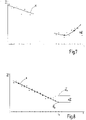
- Figure 4 and 5 illustrate the conditions in the vicinity of the impedance minimum.
- an ideal signal curve is initially assumed: After reaching an impedance minimum Z min at a point in time t1, the tissue impedance Z increases again, with the percentage increases from step to step being relatively small.
- a measurement uncertainty, ie noise can be superimposed on the measured values, so that the small individual impedance increases occurring from step to step are unsuitable for determining the minimum. This applies all the more, the smaller the time intervals ⁇ t between successive sampling processes.
- Such an increase in impedance is defined as a criterion for the increase in impedance again, which does not occur in normal signal noise, ie exceeds the signal noise.
- Such an impedance increase can be a threshold of 5%, for example, which thus does not occur in successive steps.
- the currently measured tissue impedance Z m+k according to figure 6 be compared to a series of previous impedance readings Zm, Zm+i, Zm +2 , etc.
- the minimum detector 24 can conclude that the tissue impedance has risen again, ie the passage of a minimum, if the impedance value Z m+k is at least 5% or another predetermined impedance increase threshold ⁇ Z greater than at least one of the preceding tissue impedance values. It can also be specified that the minimum detector 24 only detects a minimum Z min if the current value Z m+k is greater than at least two or more preceding impedance values.
- a modification of the minimum detection by the minimum detector 24 is in figure 7 illustrated.
- Individual impedance values are shown there as crosses, which have been determined by current and voltage measurement and subsequent impedance calculation based on this. These impedance values are subject to random fluctuations, which can result from the inhomogeneity of the biological tissue present on a microscopic scale and the denaturing processes taking place there.
- the impedance detector 24 and/or the measuring device 23 can be designed in such a way that, on the basis of the individual measured values, they determine a measuring curve K which approximates the course of the impedance Z over time t.
- the measurement curve K can be determined using splines of the nth degree or using best-fit algorithms, for example the least squares method or other suitable means.
- Polynomials, straight lines, parabolas and other curved curves and combinations of these can be used as the measurement curve K.
- essentially linear measured value curves are approximated by straight lines and non-linear measured value curves by parabolic sections.
- the exceeding of a maximum impedance rise ⁇ Z can then be determined using the course of the measurement curve K. This can be done by detecting that the slope of curve K is positive. In order to record this circumstance, it can be recorded whether and that there is a positive impedance increase ⁇ Z that exceeds a limit value of, for example, 5% of the lowest tissue impedance Z min .
- the methods mentioned above detect the impedance minimum after it has passed through the resulting renewed increase in impedance. However, it is also possible to determine that the minimum has been reached or passed through at an earlier point in time. this is in figure 8 illustrated.
- the small crosses in the diagram symbolize the tissue impedances determined at each point in time t.
- the measurement curve K is a regression line. Idealized impedance values lie on it, each of which is indicated by a small circle.
- the minimum detector determines these idealized impedance values, ie impedance values to be expected given ideal tissue behavior, and in each case compares the last idealized impedance value with the last measured impedance value.
- the tissue impedance Z x has been determined at a point in time t x .
- the impedance prognosis Z p results from the curve K.
- the difference ⁇ Z between the impedance prognosis Z p and the actual tissue impedance Z x reaches or exceeds a threshold of, for example, 5% of the prognosis value Z p again.
- the minimum detector may be configured to indicate the tissue impedance Z reaching and crossing the minimum Z min in response thereto. Instead of the 5% threshold mentioned above other thresholds and criteria may be set.
- the generator 12 presented detects a renewed increase in the tissue impedance Z, which indicates that the tissue 16 is starting to dry out and thus also the formation of steam. Spark formation is avoided by reducing the applied voltage U App .
- U App the applied voltage
- a device 10 comprises a device 12 for providing high-frequency voltage U App for contact coagulation of biological tissue 16.
- the device 12 is set up to start contact coagulation with a high voltage that is not normally suitable for contact coagulation but is otherwise used for spark coagulation Example to work more than 400V.
- the tissue impedance Z is monitored. This can be done by continuously measuring the voltage U App and the current I App flowing.
- the measuring device 23 continuously determines the tissue impedance Z from the two.
- a minimum detector 24 is provided to determine that an impedance minimum Zmin has been passed through and, if such is determined, to cause the generator control 19 to increase the voltage U App emitted by the device 12 to a value reduce, which avoids sparking and drying out of the fabric.
Description
Die Erfindung betrifft eine Einrichtung zur Kontaktkoagulation von biologischem Gewebe unter Einwirkung von elektrischem Strom.The invention relates to a device for contact coagulation of biological tissue under the influence of electric current.
Bei der Kontaktkoagulation von biologischem Gewebe laufen vorwiegend thermisch induzierte Vorgänge ab, die unter anderem zum Denaturieren des Gewebes führen, wobei vorhandene Hohlgefäße geschlossen werden sollen. Beim Anlegen einer HF-Spannung an ein biologisches Gewebe lässt sich zu Beginn des Vorgangs eine hohe elektrischer Impedanz des Gewebes beobachten. Die Stromleitung von elektrischen Ladungsträgern findet vorwiegend in extrazellularer Flüssigkeit statt, wodurch sich das Gewebe aufgrund der kinetischen Energie der bewegten elektrischen Ladungsträger zu erwärmen beginnt. Mit zunehmender Erwärmung des Gewebes sinkt die Impedanz bis sie ein Minimum erreicht. Die Erhöhung der elektrischen Leitfähigkeit tritt in einem Temperaturbereich von 60°C bis 100°C des biologischen Gewebes aufgrund seiner temperaturinduzierten strukturellen Veränderungen, die mit der Denaturierung des Gewebes einhergehen, auf. Das Gewebe wird devitalisiert, es verklumpen Eiweißmoleküle, die Zellmembran wird zerstört, wodurch Gewebsflüssigkeit freigesetzt wird. In dieser "Phase I" nimmt die Gewebeimpedanz Z fortwährend ab. Nach einiger Zeit wird die Siedetemperatur der Gewebsflüssigkeit erreicht, womit der Gewebewiderstand wieder ansteigt, was als "Phase II" bezeichnet wird. Üblicherweise erreicht die Gewebeimpedanz Z in der Phase II Werte, die deutlich über dem Impedanzminimum des Gewebes und oftmals der Anfangsimpedanz aus Phase I liegen.In the contact coagulation of biological tissue, predominantly thermally induced processes take place which, among other things, lead to the denaturing of the tissue, with existing hollow vessels being intended to be closed. When applying an HF voltage to a biological tissue, a high electrical impedance of the tissue can be observed at the beginning of the process. The current conduction of electrical charge carriers takes place predominantly in extracellular fluid, as a result of which the tissue begins to heat up due to the kinetic energy of the moving electrical charge carriers. As the tissue heats up, the impedance decreases until it reaches a minimum. The increase in electrical conductivity occurs in a temperature range of 60°C to 100°C of biological tissue due to its temperature-induced structural changes accompanying tissue denaturation. The tissue is devitalized, protein molecules clump together, the cell membrane is destroyed, which releases tissue fluid. In this "phase I" the tissue impedance Z decreases continuously. After some time, the boiling temperature of the tissue fluid is reached, causing the tissue resistance to rise again, which is referred to as "phase II". Usually the tissue impedance reaches Z in phase II values that are well above the minimum impedance of the tissue and often the initial impedance from phase I.
Aus der
Aus der
Aus der
Mit steigender Spannung während des Abfalls der Gewebeimpedanz und dem Durchlauf eines Impedanzminimums arbeitet auch die
Weiter ist aus der
Mit dem in
Bei einer schnellen Koagulation, die auf einer Funkenbildung beruht oder diese zulässt, kann es zum Ankleben von Gewebe am Instrument und damit einhergehend zu einer zum Teil nicht unerheblichen Verschmutzung des Instruments und auch des Behandlungspersonals kommen. Außerdem kann die auftretende Karbonisierung den Wundheilungsprozess erschweren.In the case of rapid coagulation, which is based on spark formation or allows for this, tissue can stick to the instrument and, as a result, the instrument and the treatment personnel can be soiled, in some cases not inconsiderably so. In addition, the carbonization that occurs can complicate the wound healing process.
Wird eine schnelle Koagulation ohne Lichtbogen durch reine Kontaktkoagulation in der Phase I mit erhöhter HF-Leistungsabgabe eines HF-Generators bewirkt, kann ein akustisch hörbares und visuell wahrnehmbares Zerreißen von behandeltem Gewebe auftreten. Dies wird durch lokales Zerreißen von Gewebe aufgrund von siedender Gewebeflüssigkeit und damit einhergehender Gewebedruckzunahme hervorgerufen. Durch das Zerreißen des Gewebes können zuvor gestillte Blutungen erneut zu bluten beginnen. Außerdem kann behandeltes pathogenes Gewebe durch das Zerreißen in gesunde Gewebeareale streuen oder auch von Behandlungspersonal aufgenommen werden.If rapid coagulation without an arc is brought about by pure contact coagulation in phase I with increased HF power output of an HF generator, an acoustically audible and visually perceptible tearing of the treated tissue can occur. This is caused by local tearing of tissue due to boiling tissue fluid and the associated increase in tissue pressure. The tearing of the tissue can cause previously stopped bleeding to start bleeding again. In addition, treated pathogenic tissue can spread to healthy tissue areas due to the tearing or can also be ingested by treatment personnel.
Es ist Aufgabe der Erfindung, ein Konzept anzugeben, mit dem sich eine schnelle Gewebekoagulation bei schonender Behandlung erreichen lässt.The object of the invention is to specify a concept with which rapid tissue coagulation can be achieved with gentle treatment.
Diese Aufgabe wird mit der Einrichtung nach Anspruch 1 gelöst. Weitere bevorzugte Ausführungsformen sind in den abhängigen Ansprüchen beschrieben.This object is achieved with the device according to
Es hat sich gezeigt, dass das Zerreißen von bereits teilweise oder ganz koaguliertem Gewebe mit dem Durchschreiten des Miniums der Gewebeimpedanz Z einhergeht. Im Impedanzminimum hat das Gewebe seinen leitfähigsten Zustand erreicht. Dies tritt bereits vor Erreichen des Siedepunkts der Gewebsflüssigkeit auf, d.h. bevor eine Temperatur von 100°C erreicht ist. Danach kommt es bei angelegter HF-Spannung zum Verdampfen der Gewebsflüssigkeit. Eine solche Verdampfung führt zu einem Druckanstieg im Gewebe und zum Zerreißen desselben und wird bei der Erfindung vermieden. Dadurch wird auch vermieden, dass kontaminiertes Gewebe verstreut, offene Wunden und Instrumente kontaminiert und OP-Personal verschmutzt oder infiziert wird. Außerdem wird ein Zerreißen von bereits koagulierten Blutgefäßen, Lymphgefäßen oder anderen Gefäßen vermieden. Durch das Fortsetzen der Koagulation mit verringerter Spannung kann die Koagulation ohne solche Effekte fortgesetzt werden, bis sich der gewünschte Gewebeeffekt ausbildet.It has been shown that the tearing of tissue that has already partially or completely coagulated is accompanied by the crossing of the minimum of the tissue impedance Z. In the impedance minimum, the tissue has reached its most conductive state. This occurs before the tissue fluid reaches its boiling point, ie before a temperature of 100°C is reached. When the HF voltage is applied, the tissue fluid then evaporates. Such evaporation leads to tissue pressure build-up and rupture and is avoided in the invention. This also avoids scattering of contaminated tissue, contamination of open wounds and instruments, and contamination or infection of surgical staff. In addition, tearing of already coagulated blood vessels, lymphatic vessels or other vessels is avoided. By continuing the coagulation with reduced tension, the coagulation can be continued without such effects until the desired tissue effect develops.
Der vorgeschlagene neue Kontaktkoagulationsmodus arbeitet solange mit erhöhtem Leistungseintrag, bis das Impedanzminimum erreicht wird. Hierbei wird in der Phase I bis zum Erreichen des Impedanzminimums die maximal mögliche HF-Energie durch Abgabe einer hohen HF-Spannung in das Gewebe eingetragen. Der Beginn der Koagulation erfolgt bei der Berührung des Instruments mit dem Gewebe mit maximaler Leistungsabgabe des Generators, d.h. mit einer HF-Spannung, die unabhängig vom Strom vorzugsweise deutlich über 200V liegt. Die Entstehung von Dampf im Gewebe und somit das Zerreißen von Gewebe wird jedoch verhindert, indem die Applikation erhöhter HF-Spannung abgebrochen wird, sobald ein Impedanzminimum detektiert wird. Es wird danach lediglich eine reduzierte HF-Spannung bereitgestellt.The proposed new contact coagulation mode works with increased power input until the impedance minimum is reached. In phase I, the maximum possible HF energy is applied to the tissue by delivering a high HF voltage until the impedance minimum is reached. The coagulation begins when the instrument touches the tissue with the maximum power output of the generator, ie with an HF voltage which is preferably well above 200V, independently of the current. However, the formation of vapor in the tissue and thus the tearing of tissue is prevented by stopping the application of increased HF voltage as soon as an impedance minimum is detected. Only a reduced HF voltage is then provided.
Bei der Erfindung ist in der Generatorsteuerung ein Einstellwert für die zu applizierende Spannung hinterlegt. Die Generatorsteuerung ist dann darauf eingerichtet, zu Beginn eines Koagulationsprogramms den Generator zu veranlassen, die zu applizierende Spannung mit einem Wert bereitzustellen, der größer ist als der Einstellwert. In der Erfindung ist die zu applizierende Spannung zu Beginn eines Koagulationsvorgangs mindestens doppelt so groß wie der Einstellwert. Wenn der Anwender die gewohnte, zur Kontaktkoagulation geeignete Spannung (z.B. 200 V) einstellt, arbeitet er bei dem erfindungsgemäßen System zu Beginn eines Koagulationsvorgangs mit einer Spannung von mindestens 400 V. Zur Funkenbildung kommt es jedoch deswegen nicht, weil die Spannung reduziert wird, sobald ein Impedanzminimum durchlaufen ist und Dampfbildung droht. Durch die Vermeidung von Dampfbildung kann auch die Funkenbildung, das damit einhergehende Platzen von Dampfblasen im Gewebe und damit einhergehende Nachteile vermieden werden.In the case of the invention, a setting value for the voltage to be applied is stored in the generator control. The generator control is then set up to prompt the generator at the beginning of a coagulation program to provide the voltage to be applied at a value that is greater than the set value. In the invention, the voltage to be applied at the beginning of a coagulation process is at least twice the set value. If the user sets the usual voltage suitable for contact coagulation (e.g. 200 V), he works with the system according to the invention at the beginning of a coagulation process with a voltage of at least 400 V. However, sparking does not occur because the voltage is reduced as soon as an impedance minimum has passed and vapor formation is imminent. By avoiding the formation of steam, the formation of sparks, the associated bursting of steam bubbles in the tissue and the associated disadvantages can also be avoided.
Bei der Erfindung wird nach Erkennung des ersten Minimums der Gewebeimpedanz der Generator veranlasst, die zu applizierende Spannung mit einem Wert bereitzustellen, der nicht größer als der Einstellwert ist. Der Einstellwert wird dabei auf einen Wert festgelegt, der eine fortgesetzte Koagulation ohne Funkenbildung ermöglicht. Vorzugsweise ist die Generatorsteuerung darauf eingerichtet, in Reaktion auf die Erkennung eines zweiten oder weiteren Minimums der Gewebeimpedanz Z den Generator zu veranlassen, die zu applizierende Spannung auf einen Wert zu reduzieren, der kleiner als der Einstellwert ist. Vorzugsweise ist dieser Wert um einen vorgegebenen Prozentsatz, beispielsweise 10%, kleiner als die zuvor gelieferte Spannung.In the case of the invention, after detection of the first minimum of the tissue impedance, the generator is prompted to provide the voltage to be applied with a value that is not greater than the set value. The setting value is set to a value that enables continued coagulation without sparking. The generator controller is preferably set up to cause the generator to react to the detection of a second or further minimum of the tissue impedance Z Reduce voltage to a value smaller than the setting value. Preferably, this value is a predetermined percentage, for example 10%, lower than the previously supplied voltage.
Weiter kann die Generatorsteuerung darauf eingerichtet sein, die HF-Applikation des Generators zu beenden, wenn die zu applizierende Spannung einen Wert erreicht hat, der einen festgelegten Bruchteil des eingestellten Werts nicht überschreitet bzw. unterschreitet. Dieser festgelegte Bruchteil kann beispielsweise 60% der eingestellten Spannung betragen. Mit einer solchen Einrichtung wird eine schnelle großvolumige Koagulation erreicht. Der Einstellwert der zu applizierenden Spannung kann in Stufen oder stufenlos variable vorgebbar sein. Vorzugsweise sind dazu entsprechende Einstellmittel an dem das Instrument speisenden Gerät vorgesehen. Die Überwachung der Gewebeimpedanz kann kontinuierlich oder in eng aufeinanderfolgenden Zeitpunkten quasi kontinuierlich erfolgen. Vorzugsweise sind die Zeitabstände zwischen einzelnen Messungen des Gewebewiderstands geringer als 0,2 ms. Vorzugsweise betragen die Zeitabstände etwa 100 ps. Damit kann sehr schnell auf den sich ändernden Gewebewiderstand reagiert werden.Furthermore, the generator controller can be set up to end the HF application of the generator when the voltage to be applied has reached a value that does not exceed or falls below a specified fraction of the set value. This fixed fraction can be, for example, 60% of the set voltage. With such a device, rapid, large-volume coagulation is achieved. The setting value of the voltage to be applied can be specified in steps or in an infinitely variable manner. Appropriate setting means are preferably provided for this purpose on the device feeding the instrument. The tissue impedance can be monitored continuously or in a quasi-continuous manner at points in time that follow one another in close succession. The time intervals between individual measurements of the tissue resistance are preferably less than 0.2 ms. The time intervals are preferably about 100 ps. This allows you to react very quickly to the changing tissue resistance.
Bei der Erfassung der aktuellen Gewebeimpedanz in kurzen Zeitabständen werden vorzugsweise die bereitgestellte applizierte Spannung und der durch das biologische Gewebe fließende Strom, sowie deren Phasenlage zueinander in Zeitfenstern erfasst, deren Länge mindestens so lang ist wie eine Schwingungsperiode, weiter vorzugsweise mindestens so lang wie mehrere Schwingungsperioden der HF-Spannung. Vorzugsweise werden dabei mindestens ein Kennwert der anliegenden Spannung und mindestens ein Kennwert des fließenden Stroms erfasst. Ein Kennwert der Spannung kann die Spitzen-Spitzen-Spannung (doppelte Spitzenspannung), die Scheitelspannung (einfache Spitzenspannung), der Mittelwert des Betrags der Spannung, der Gleichrichtwert, der Effektivwert oder dergleichen sein. Entsprechendes gilt für den fließenden Strom. Ein Kennwert des Stroms kann der Spitzen-Spitzen-Strom (doppelter Spitzenstrom), der Scheitelstrom (einfacher Spitzenstrom), der Mittelwert des Betrags des Stroms, der Gleichrichtwert, der Effektivwert oder dergleichen sein. Ein Kennwert für die Phasenlage kann der Phasenwinkel ϕ zwischen den beiden genannten Kennwerten sein, der die Verschiebung der beiden Kennwerte zueinander beschreibt.When detecting the current tissue impedance at short time intervals, the applied voltage and the current flowing through the biological tissue, as well as their phase relationship to one another, are preferably detected in time windows whose length is at least as long as one oscillation period, more preferably at least as long as several oscillation periods the HF voltage. Preferably, at least one characteristic value of the applied Voltage and at least one characteristic of the flowing current detected. A characteristic value of the voltage may be the peak-to-peak voltage (double peak voltage), the crest voltage (single peak voltage), the average value of the voltage, the rectified value, the effective value, or the like. The same applies to the flowing current. A characteristic value of the current may be the peak-to-peak current (double peak current), the peak current (single peak current), the mean value of the magnitude of the current, the rectified value, the effective value, or the like. A parameter for the phase position can be the phase angle φ between the two parameters mentioned, which describes the shift of the two parameters relative to one another.
Als Gewebeimpedanz Z kann der Quotient aus einem Kennwert der Spannung und einem Kennwert des Stroms mit Bezug auf die Phasenlage genommen werden. Bei einer vorteilhaften Ausführungsform wird dieser Quotient mit einer oder mehreren zuvor ermittelten Quotienten verglichen, um das Erreichen und Durchlaufen eines Gewebewiderstandsminimums zu erkennen. Der Minimumdetektor ist darauf eingerichtet, das Gewebeimpedanzminimum an die Generatorsteuerung zu signalisieren. 
![]()
![]()
In einer anderen Ausführungsform kann der Minimumdetektor darauf eingerichtet sein, den Trend der Gewebeimpedanz anhand gemessener Gewebeimpedanzen zu ermitteln, um eine Prognose für die nächsten zu messenden Gewebeimpedanz zu treffen, wobei das Erreichen und Durchlaufen eines Gewebeimpedanzminimums dann signalisiert wird, wenn die nächste gemessene Gewebeimpedanz Z um einen vorbestimmten Wert über der Prognose für die Nächste zu messende Gewebeimpedanz liegt. Damit kann das Erreichen des Gewebeimpedanzminimums vor dem Wiederanstieg derselben erfasst und die Bildung von Dampfblasen noch schneller unterdrückt werden.In another embodiment, the minimum detector may be configured to detect the trend in tissue impedance based on measured tissue impedances in order to make a prognosis for the next tissue impedance to be measured, with reaching and passing through a tissue impedance minimum being signaled when the next measured tissue impedance Z is a predetermined value above the prognosis for the next tissue impedance to be measured. In this way, reaching the tissue impedance minimum can be detected before it rises again, and the formation of vapor bubbles can be suppressed even more quickly.
Weitere Ausführungsformen und vorteilhafte Details sind Gegenstand der Zeichnung sowie der Beschreibung und/oder der Patentansprüche. Es zeigen:
-
Figur 1 -
Figur 2 -
Figur 3 ein Zeitdiagramm zur Veranschaulichung der Messung des Gewebewiderstands, -
Figur 4 bis 8 weitere Diagramme zur Veranschaulichung der Betriebsweise der Einrichtung in verschiedenen Ausführungsformen,
-
figure 1 the device according to the invention with a generator and an instrument in a schematic representation, -
figure 2 the operation of the generator in the diagram, -
figure 3 a time diagram to illustrate the measurement of tissue resistance, -
Figure 4 to 8 further diagrams to illustrate the operation of the device in different embodiments,
![]()
![]()
Das Gerät 12 enthält einen Generator 17 zur Erzeugung hochfrequenter elektrischer Spannungen und Ströme. Der Generator 17 ist an eine Betriebsspannung angeschlossen, die von einem Netzteil 18 bereitgestellt wird. Der Betrieb des Generators 17 wird von einer Generatorsteuerung 19 bestimmt, die zum Beispiel ein elektronisches Schalt- oder Verstärkungselement 20 steuert, um einen zu dem Generator 17 gehörigen Schwingkreis anzuregen. Die Generatorsteuerung 19 kann ein oder mehrere Bedienelemente 21 aufweisen, mittels derer Vorgaben für den Betrieb des Generators gemacht und Einstellungen durch einen Anwender vorgenommen werden können. Beispielsweise kann zu den voreinzustellenden Größen ein Einstellwert UEin gehören, mit dem der Anwender ihm geläufige Spannungswerte für die Kontaktkoagulation einstellt (zum Beispiel 200 V). Weiter können zu den Einstellwerten die Betriebsart oder sonstige Parameter gehören, beispielsweise, das gewünschte Koagulationsvolumen oder die gewünschte Koagulationszeit, die maximal zu applizierende Energie oder dergleichen. Weiter können sonstige Parameter wie Crestfaktor, Maximalstrom, maximale Leistung und dergleichen einstellbar sein. Der Generator 17 stellt eine Spannung UApp bereit, die an der Elektrode 22 des Instruments 11 bereitsteht und auf deren Grund sich ein Strom IApp durch das Gewebe 16 ergibt.The
Die an das Gewebe angelegte Spannung UApp und der durch das Gewebe fließende Strom IApp werden von einer Messeinrichtung 23 erfasst und daraus Messwerte abgeleitet. Die Messeinrichtung 23 bestimmt aus dem Messwert des Stroms IApp und dem Messwert der Spannung UApp die aktuelle Gewebeimpedanz Z. Ein Minimumdetektor 24 ist dabei dazu vorgesehen, zu erkennen, ob oder dass die Gewebeimpedanz Z ein Impedanzminimum erreicht oder durchlaufen hat. In einem solchen Fall signalisiert der Minimumdetektor 24 dies der Generatorsteuerung 19.The voltage U App applied to the tissue and the current I App flowing through the tissue are recorded by a measuring
Die Generatorsteuerung 19, die Messeinrichtung 23 und der Minimumdetektor 24 sind Funktionsblöcke. Sie können baulich zu einer einzigen Baugruppe integriert oder auf mehrere einzelne Baugruppen aufgeteilt sein. Insbesondere können die Messeinrichtung 23 und der Minimumdetektor 24 mit der Generatorsteuerung zu einer Baugruppe zusammengefasst sein. Die Baugruppen können physische Module oder auch Programmmodule oder dergleichen sein. Beispielsweise kann die Messeinrichtung 23. sowohl den zu messenden Strom IApp als auch die zu messende Spannung UApp mittels Analog/Digital-Wandler in Datenpaare umwandeln und dann mittels eines Rechenblocks die zugehörigen Gewebeimpedanzwerte bestimmen. Die Gewebeimpedanzwerte können zum Beispiel in einem Speicher zur weiteren Verarbeitung bereitgehalten werden.The
Der Minimumdetektor 24 kann dann durch eine Programmroutine gebildet sein, die in den Datenpaaren nach einem Impedanzminimum sucht. Die Gewebeimpedanz kann dabei als Quotient eines der Kennwerte der jeweils gemessenen Spannung UApp und eines der Kennwerte des gemessen Stroms IApp definiert sein.
Die Generatorsteuerung 19 ist darauf eingerichtet, anhand der Mess- bzw. Rechenwerte für die Gewebeimpedanz Z verschiedene Generatorspannungen UApp festzulegen, wie es prinzipiell in
Der Vorgang kann fortgesetzt werden bis die applizierte Spannung UApp einen unteren Grenzwert erreicht, der zum Beispiel 60 % des Einstellwerts UEin betragen kann. Ist dies der Fall kann die Generatorsteuerung die Aktivierung durch Steuerung des elektronischen Schaltelements 20 abbrechen. Die Koagulation ist damit beendet.The process can be continued until the applied voltage U App reaches a lower limit value, which can be 60% of the set value U Ein , for example. If this is the case, the generator control can cancel the activation by controlling the
Der Minimumdetektor 24 kann das Impedanzminimum nach jedem geeigneten Verfahren zur Auswertung von Messreihen bestimmen. ![]()
![]()
Zur Erkennung der Zunahme der Gewebeimpedanz kann die aktuell gemessene Gewebeimpedanz Z m+k gemäß
Eine Abwandlung der Minimumserfassung durch den Minimumdetektor 24 ist in
Die vorgenannten Verfahren erfassen das Impedanzminimum nach dessen Durchlaufen, durch den sich einstellenden Wiederanstieg der Impedanz. Es ist jedoch auch möglich, das Erreichen des Minimums bzw. das Durchlaufen desselben zu einem früheren Zeitpunkt festzustellen. Dies ist in
Der vorgestellte Generator 12 stellt einen Wiederanstieg der Gewebeimpedanz Z fest, der auf ein Beginnen des Austrocken des Gewebes 16 und somit auch Dampfbildung hindeutet. Durch Reduktion der angelegten Spannung UApp wird Funkenbildung vermieden. Andererseits wird zu Beginn der Bestromung des biologischen Gewebes 16 mit überhöhter Spannung (zum Beispiel UApp ≥ 2*UEin) gearbeitet, wodurch eine sehr schnelle Koagulation erfolgt. Die sonst bei überhöhter Spannung auftretenden nachteiligen Erscheinungen wie Zerreißen von Gewebe, Aufplatzen von Gefäßen, unerwünschte Funkenbildung und somit Karbonisierung werden vermieden.The
Eine erfindungsgemäße Einrichtung 10 umfasst ein Gerät 12 zur Bereitstellung von hochfrequenter Spannung UApp zur Kontaktkoagulation von biologischem Gewebe 16. Das Gerät 12 ist darauf eingerichtet, zu Beginn der Kontaktkoagulation mit einer hohen normalerweise zur Kontaktkoagulation nicht geeigneten, sondern sonst zur Funkenkoagulation verwendeten Spannung von zum Beispiel mehr als 400 V zu arbeiten. Während des Betriebs des Geräts 12 wird die Gewebeimpedanz Z überwacht. Dies kann durch fortwährendes Messen der Spannung UApp und des fließenden Stroms IApp geschehen. Aus beiden bestimmt die Messeinrichtung 23 fortwährend die Gewebeimpedanz Z. Ein Minimumdetektor 24 ist dazu vorgesehen, das Durchlaufen eines Impedanzminimums Zmin festzustellen und, falls solches festgestellt wird, die Generatorsteuerung 19 zu veranlassen, die von dem Gerät 12 abgegebene Spannung UApp auf einen Wert zu reduzieren, der Funkenbildung sowie Austrocknen des Gewebes vermeidet.
Claims (12)
- Arrangement (10) for contact coagulation of biological tissue (16), with:- a generator (17) for provision of HF voltage (UApp) and the emission of HF current (IApp),- a generator controller (19), by means of which the HF voltage (UApp) provided by the generator can be influenced,- an instrument (11) with at least one electrode (22) which is supplied with HF current by the generator (17),- a measuring device (23) for monitoring the tissue impedance (Z),- a minimum detector (24) for detecting a minimum (Z min) of the tissue impedance (Z),wherein the minimum detector (24) is connected to the generator controller (19) in order to induce the generator (17), on detection of a minimum (Z min) of the tissue impedance (Z), then to provide a reduced HF voltage (UApp) so as to avoid vapour formation,wherein a setting value (UEin) for the voltage (UApp) to be applied, which is suitable for spark-free contact coagulation, is stored in the generator controller (19) and the generator controller (19) is configured, at the start of a coagulation process during which the tissue has its initial impedance (Z o), to induce the generator (17) to provide the voltage (UApp) to be applied with a value which is greater than the setting value (UEin),wherein the voltage (UApp) to be applied at the start of a coagulation process is at least twice as great as the setting value (UEin) and not normally suitable for spark-free contact coagulation,and wherein the first voltage reduction reduces the voltage to the setting value (UEin).
- Arrangement according to claim 1, characterised in that the generator controller (19) is configured, in response to the detection of a second or further minimum (Z minII) of the tissue impedance (Z), to induce the generator (17) to provide the voltage (UApp) to be applied with a value which is lower than the setting value (UEin).
- Arrangement according to claim 2, characterised in that the generator controller (19) is configured, in response to the detection of a second or further minimum (Z minII) of the tissue impedance (Z), to induce the generator (17) to provide the voltage (UApp) to be applied with a value which is 10% lower than the previously supplied voltage (UApp).
- Arrangement according to claim 2 or 3, characterised in that the generator voltage (19) is configured to end the HF application of the generator when the voltage (UApp) to be applied has reached a value which does not exceed an established fraction of the set value (UEin).
- Arrangement according to any of the preceding claims, characterised in that the setting value (UEin) is variably predefinable by means of a setting means.
- Arrangement according to any of the preceding claims, characterised in that the actual tissue impedance (Z) is detected at time intervals (Δt) which are shorter than 0.2 ms, preferably at most 0.1 ms.
- Arrangement according to claim 6, characterised in that the measuring device (23) is configured to carry out the detection of tissue impedance (Z) in sampling windows (tm), the length of which is at least as great as the oscillation period of the voltage (UApp).
- Arrangement according to claim 7, characterised in that the measuring device (23) is configured, during the measuring period, to detect at least one characteristic value of the applied voltage (UApp), at least one characteristic value of the flowing current (IApp), and at least one characteristic value of the phase position (ϕ) between applied voltage and flowing current, and from these to form a quotient relating to the shift in phase position between applied voltage and flowing current which characterises the tissue impedance (Z).
- Arrangement according to any of claims 6 to 8, characterised in that the measuring device (23) is configured to form an ongoing mean value from several tissue resistances (Z) detected at time intervals (Δt).
- Arrangement according to claim 8, characterised in that the minimum detector (24) is configured to signal the reaching and passing of a tissue impedance minimum (Z min) on establishing a rise in tissue impedance (Z) in relation to a previously measured tissue impedance (Z).
- Arrangement according to claim 8, characterised in that the minimum detector (24) is configured to signal the reaching and passing of a tissue impedance minimum (Z min) on establishing a rise in tissue impedance (Z) or in a smoothed mean value of the tissue impedance in relation to the lowest tissue impedance of a group of tissue resistances previously measured.
- Arrangement according to any of the preceding claims, characterised in that the minimum detector (24) is configured to determine the trend of the development of tissue impedance (Z) in order to make a prognosis (Z p) for the next tissue impedance to be measured, wherein the reaching and passing of a tissue impedance minimum (Z min) is signalled when the next measured tissue impedance (Z) lies by a predefined value (ΔZ) above the next tissue impedance (Z) to be measured.
Priority Applications (7)
| Application Number | Priority Date | Filing Date | Title |
|---|---|---|---|
| EP14183771.6A EP2992848B1 (en) | 2014-09-05 | 2014-09-05 | Device for contact coagulation of biological tissue |
| PL14183771.6T PL2992848T3 (en) | 2014-09-05 | 2014-09-05 | Device for contact coagulation of biological tissue |
| US14/838,451 US10413348B2 (en) | 2014-09-05 | 2015-08-28 | Arrangement for contact coagulation of biological tissue |
| CN201510546994.1A CN105395247B (en) | 2014-09-05 | 2015-08-31 | A kind of device of the contact solidification for biological tissue |
| BR102015021329-8A BR102015021329B1 (en) | 2014-09-05 | 2015-09-02 | ARRANGEMENT FOR BIOLOGICAL TISSUE CONTACT COAGULATION |
| KR1020150125226A KR101787829B1 (en) | 2014-09-05 | 2015-09-04 | An arrangement for contact coagulation of biological tissue |
| JP2015174876A JP6097802B2 (en) | 2014-09-05 | 2015-09-04 | Device for contact coagulation of living tissue |
Applications Claiming Priority (1)
| Application Number | Priority Date | Filing Date | Title |
|---|---|---|---|
| EP14183771.6A EP2992848B1 (en) | 2014-09-05 | 2014-09-05 | Device for contact coagulation of biological tissue |
Publications (2)
| Publication Number | Publication Date |
|---|---|
| EP2992848A1 EP2992848A1 (en) | 2016-03-09 |
| EP2992848B1 true EP2992848B1 (en) | 2022-12-28 |
Family
ID=51564448
Family Applications (1)
| Application Number | Title | Priority Date | Filing Date |
|---|---|---|---|
| EP14183771.6A Active EP2992848B1 (en) | 2014-09-05 | 2014-09-05 | Device for contact coagulation of biological tissue |
Country Status (7)
| Country | Link |
|---|---|
| US (1) | US10413348B2 (en) |
| EP (1) | EP2992848B1 (en) |
| JP (1) | JP6097802B2 (en) |
| KR (1) | KR101787829B1 (en) |
| CN (1) | CN105395247B (en) |
| BR (1) | BR102015021329B1 (en) |
| PL (1) | PL2992848T3 (en) |
Families Citing this family (7)
| Publication number | Priority date | Publication date | Assignee | Title |
|---|---|---|---|---|
| JP6454211B2 (en) * | 2015-03-31 | 2019-01-16 | シスメックス株式会社 | Sample analyzer, blood coagulation analyzer, sample analysis method, and computer program |
| DE112016007214T5 (en) * | 2016-09-13 | 2019-06-06 | Olympus Corporation | Energy treatment system and output control method therefor |
| WO2018102376A1 (en) * | 2016-11-29 | 2018-06-07 | St. Jude Medical, Cardiology Division, Inc. | Electroporation systems and catheters for electroporation systems |
| WO2018167877A1 (en) | 2017-03-15 | 2018-09-20 | オリンパス株式会社 | Energy source device |
| US11744631B2 (en) * | 2017-09-22 | 2023-09-05 | Covidien Lp | Systems and methods for controlled electrosurgical coagulation |
| CN112842514B (en) * | 2020-12-31 | 2022-04-12 | 杭州堃博生物科技有限公司 | Ablation operation prompting method, electronic device and computer readable storage medium |
| KR20230125874A (en) * | 2022-02-22 | 2023-08-29 | 한양대학교 에리카산학협력단 | Electro-surgical apparatus, impedance measurement apparatus of the same, method for controlling of energy with regard to electrocoagulation and for determining of impedance by the same |
Family Cites Families (10)
| Publication number | Priority date | Publication date | Assignee | Title |
|---|---|---|---|---|
| DE3622337C2 (en) | 1986-07-03 | 1996-05-09 | Lindenmeier Heinz | High frequency generator with automatic power control for high frequency coagulation |
| US6843789B2 (en) * | 2000-10-31 | 2005-01-18 | Gyrus Medical Limited | Electrosurgical system |
| GB0026586D0 (en) * | 2000-10-31 | 2000-12-13 | Gyrus Medical Ltd | An electrosurgical system |
| JP2002306505A (en) * | 2001-04-13 | 2002-10-22 | Olympus Optical Co Ltd | Electrosurgery system |
| JP4656755B2 (en) | 2001-05-07 | 2011-03-23 | オリンパス株式会社 | Electrosurgical equipment |
| US6733498B2 (en) | 2002-02-19 | 2004-05-11 | Live Tissue Connect, Inc. | System and method for control of tissue welding |
| UA75342C2 (en) * | 2002-06-19 | 2006-04-17 | Borys Yevhenovych Paton | Technique for welding human and animal soft tissues |
| US20070282320A1 (en) | 2006-05-30 | 2007-12-06 | Sherwood Services Ag | System and method for controlling tissue heating rate prior to cellular vaporization |
| PL2520240T3 (en) | 2011-05-03 | 2017-05-31 | Erbe Elektromedizin Gmbh | Device for tissue fusion or coagulation by means of electric force with negative source impedance |
| PL2520241T3 (en) | 2011-05-03 | 2017-02-28 | Erbe Elektromedizin Gmbh | Device for tissue fusion or coagulation by means of tissue resistance-dependent voltage-controlled electric force |
-
2014
- 2014-09-05 EP EP14183771.6A patent/EP2992848B1/en active Active
- 2014-09-05 PL PL14183771.6T patent/PL2992848T3/en unknown
-
2015
- 2015-08-28 US US14/838,451 patent/US10413348B2/en active Active
- 2015-08-31 CN CN201510546994.1A patent/CN105395247B/en active Active
- 2015-09-02 BR BR102015021329-8A patent/BR102015021329B1/en active IP Right Grant
- 2015-09-04 KR KR1020150125226A patent/KR101787829B1/en active IP Right Grant
- 2015-09-04 JP JP2015174876A patent/JP6097802B2/en active Active
Also Published As
| Publication number | Publication date |
|---|---|
| BR102015021329A2 (en) | 2016-03-08 |
| CN105395247A (en) | 2016-03-16 |
| KR101787829B1 (en) | 2017-10-18 |
| JP6097802B2 (en) | 2017-03-15 |
| CN105395247B (en) | 2019-02-22 |
| US20160066978A1 (en) | 2016-03-10 |
| KR20160029706A (en) | 2016-03-15 |
| JP2016055172A (en) | 2016-04-21 |
| PL2992848T3 (en) | 2023-03-13 |
| BR102015021329B1 (en) | 2022-01-04 |
| EP2992848A1 (en) | 2016-03-09 |
| US10413348B2 (en) | 2019-09-17 |
Similar Documents
| Publication | Publication Date | Title |
|---|---|---|
| EP2992848B1 (en) | Device for contact coagulation of biological tissue | |
| EP2306918B1 (en) | Electrosurgical device for the treatment of a biological tissue | |
| DE69831525T2 (en) | Electrosurgical generator with adaptive power control | |
| EP1816969B1 (en) | Hf surgical instrument | |
| EP2367493B1 (en) | Electrosurgical device having a temperature measurement device for determining a temperature and/or a temperature change at a neutral electrode | |
| EP2540244B1 (en) | Device for optimised coagulation of biological tissue | |
| EP2574145A2 (en) | Method for preparing food by means of an induction heating device and induction heating device | |
| EP2805682A1 (en) | Power controlled coagulation device | |
| EP3569171B1 (en) | Device and method for setting parameters for creating plasma in an aqueous environment | |
| EP2520240B1 (en) | Device for tissue fusion or coagulation by means of electric force with negative source impedance | |
| EP3011923B1 (en) | Device for metal detection when acting on biological tissue by means of a spark-forming electrosurgical instrument | |
| EP2520241B1 (en) | Device for tissue fusion or coagulation by means of tissue resistance-dependent voltage-controlled electric force | |
| DE102008050635A1 (en) | Method and apparatus for controlling a cooled RF ablation probe | |
| EP3030181B1 (en) | Device for controlling a treatment process | |
| WO2018069533A1 (en) | High-frequency generator for connecting an instrument for treating body tissue | |
| CH680702A5 (en) | ||
| EP3884894A1 (en) | Electrosurgical generator, electrosurgical system and method for operating an electrosurgical generator | |
| EP3277212A1 (en) | Plasma-surgical device and method for operating a device of this type | |
| EP3339827B1 (en) | Core temperature sensor for a cooking device, method for detecting the setting of a core temperature sensor and method for determining the thermal conductivity of a cooking device | |
| WO2007000247A1 (en) | Measuring cell and method carried out using said measuring cell for determining the degree of dissociation of biological cells induced by electroporation | |
| DE102017110473A1 (en) | Electrosurgical system with a control and measuring device and method for operating the electrosurgical system | |
| WO2015158921A1 (en) | Apparatus and method for operating a light generator | |
| DE102012220665A1 (en) | Electrosurgical instrument for use with high frequency-surgical device for ablation and coagulation of biological tissue, has electrodes electrically controlled, where electrode pair is formed between electrodes separated from each other | |
| DE10054963A1 (en) | High frequency generator for performing high frequency surgery varies pulse duration and interval to maintain constant output voltage peak or spark intensity if maximum mean power is exceeded |
Legal Events
| Date | Code | Title | Description |
|---|---|---|---|
| PUAI | Public reference made under article 153(3) epc to a published international application that has entered the european phase |
Free format text: ORIGINAL CODE: 0009012 |
|
| AK | Designated contracting states |
Kind code of ref document: A1 Designated state(s): AL AT BE BG CH CY CZ DE DK EE ES FI FR GB GR HR HU IE IS IT LI LT LU LV MC MK MT NL NO PL PT RO RS SE SI SK SM TR |
|
| AX | Request for extension of the european patent |
Extension state: BA ME |
|
| 17P | Request for examination filed |
Effective date: 20160317 |
|
| RBV | Designated contracting states (corrected) |
Designated state(s): AL AT BE BG CH CY CZ DE DK EE ES FI FR GB GR HR HU IE IS IT LI LT LU LV MC MK MT NL NO PL PT RO RS SE SI SK SM TR |
|
| RAP1 | Party data changed (applicant data changed or rights of an application transferred) |
Owner name: ERBE ELEKTROMEDIZIN GMBH |
|
| STAA | Information on the status of an ep patent application or granted ep patent |
Free format text: STATUS: EXAMINATION IS IN PROGRESS |
|
| 17Q | First examination report despatched |
Effective date: 20170406 |
|
| STAA | Information on the status of an ep patent application or granted ep patent |
Free format text: STATUS: EXAMINATION IS IN PROGRESS |
|
| GRAJ | Information related to disapproval of communication of intention to grant by the applicant or resumption of examination proceedings by the epo deleted |
Free format text: ORIGINAL CODE: EPIDOSDIGR1 |
|
| INTG | Intention to grant announced |
Effective date: 20220530 |
|
| INTC | Intention to grant announced (deleted) | ||
| GRAP | Despatch of communication of intention to grant a patent |
Free format text: ORIGINAL CODE: EPIDOSNIGR1 |
|
| STAA | Information on the status of an ep patent application or granted ep patent |
Free format text: STATUS: GRANT OF PATENT IS INTENDED |
|
| INTG | Intention to grant announced |
Effective date: 20220718 |
|
| RIN1 | Information on inventor provided before grant (corrected) |
Inventor name: KEGREISS, MARC Inventor name: KELLER, SANDRA |
|
| GRAS | Grant fee paid |
Free format text: ORIGINAL CODE: EPIDOSNIGR3 |
|
| GRAA | (expected) grant |
Free format text: ORIGINAL CODE: 0009210 |
|
| STAA | Information on the status of an ep patent application or granted ep patent |
Free format text: STATUS: THE PATENT HAS BEEN GRANTED |
|
| AK | Designated contracting states |
Kind code of ref document: B1 Designated state(s): AL AT BE BG CH CY CZ DE DK EE ES FI FR GB GR HR HU IE IS IT LI LT LU LV MC MK MT NL NO PL PT RO RS SE SI SK SM TR |
|
| REG | Reference to a national code |
Ref country code: GB Ref legal event code: FG4D Free format text: NOT ENGLISH |
|
| REG | Reference to a national code |
Ref country code: CH Ref legal event code: EP |
|
| REG | Reference to a national code |
Ref country code: DE Ref legal event code: R096 Ref document number: 502014016463 Country of ref document: DE |
|
| REG | Reference to a national code |
Ref country code: AT Ref legal event code: REF Ref document number: 1539969 Country of ref document: AT Kind code of ref document: T Effective date: 20230115 |
|
| REG | Reference to a national code |
Ref country code: IE Ref legal event code: FG4D Free format text: LANGUAGE OF EP DOCUMENT: GERMAN |
|
| REG | Reference to a national code |
Ref country code: LT Ref legal event code: MG9D |
|
| PG25 | Lapsed in a contracting state [announced via postgrant information from national office to epo] |
Ref country code: SE Free format text: LAPSE BECAUSE OF FAILURE TO SUBMIT A TRANSLATION OF THE DESCRIPTION OR TO PAY THE FEE WITHIN THE PRESCRIBED TIME-LIMIT Effective date: 20221228 Ref country code: NO Free format text: LAPSE BECAUSE OF FAILURE TO SUBMIT A TRANSLATION OF THE DESCRIPTION OR TO PAY THE FEE WITHIN THE PRESCRIBED TIME-LIMIT Effective date: 20230328 Ref country code: LT Free format text: LAPSE BECAUSE OF FAILURE TO SUBMIT A TRANSLATION OF THE DESCRIPTION OR TO PAY THE FEE WITHIN THE PRESCRIBED TIME-LIMIT Effective date: 20221228 Ref country code: FI Free format text: LAPSE BECAUSE OF FAILURE TO SUBMIT A TRANSLATION OF THE DESCRIPTION OR TO PAY THE FEE WITHIN THE PRESCRIBED TIME-LIMIT Effective date: 20221228 |
|
| REG | Reference to a national code |
Ref country code: NL Ref legal event code: MP Effective date: 20221228 |
|
| PG25 | Lapsed in a contracting state [announced via postgrant information from national office to epo] |
Ref country code: RS Free format text: LAPSE BECAUSE OF FAILURE TO SUBMIT A TRANSLATION OF THE DESCRIPTION OR TO PAY THE FEE WITHIN THE PRESCRIBED TIME-LIMIT Effective date: 20221228 Ref country code: LV Free format text: LAPSE BECAUSE OF FAILURE TO SUBMIT A TRANSLATION OF THE DESCRIPTION OR TO PAY THE FEE WITHIN THE PRESCRIBED TIME-LIMIT Effective date: 20221228 Ref country code: HR Free format text: LAPSE BECAUSE OF FAILURE TO SUBMIT A TRANSLATION OF THE DESCRIPTION OR TO PAY THE FEE WITHIN THE PRESCRIBED TIME-LIMIT Effective date: 20221228 Ref country code: GR Free format text: LAPSE BECAUSE OF FAILURE TO SUBMIT A TRANSLATION OF THE DESCRIPTION OR TO PAY THE FEE WITHIN THE PRESCRIBED TIME-LIMIT Effective date: 20230329 |
|
| PG25 | Lapsed in a contracting state [announced via postgrant information from national office to epo] |
Ref country code: NL Free format text: LAPSE BECAUSE OF FAILURE TO SUBMIT A TRANSLATION OF THE DESCRIPTION OR TO PAY THE FEE WITHIN THE PRESCRIBED TIME-LIMIT Effective date: 20221228 |
|
| PG25 | Lapsed in a contracting state [announced via postgrant information from national office to epo] |
Ref country code: SM Free format text: LAPSE BECAUSE OF FAILURE TO SUBMIT A TRANSLATION OF THE DESCRIPTION OR TO PAY THE FEE WITHIN THE PRESCRIBED TIME-LIMIT Effective date: 20221228 Ref country code: RO Free format text: LAPSE BECAUSE OF FAILURE TO SUBMIT A TRANSLATION OF THE DESCRIPTION OR TO PAY THE FEE WITHIN THE PRESCRIBED TIME-LIMIT Effective date: 20221228 Ref country code: PT Free format text: LAPSE BECAUSE OF FAILURE TO SUBMIT A TRANSLATION OF THE DESCRIPTION OR TO PAY THE FEE WITHIN THE PRESCRIBED TIME-LIMIT Effective date: 20230428 Ref country code: ES Free format text: LAPSE BECAUSE OF FAILURE TO SUBMIT A TRANSLATION OF THE DESCRIPTION OR TO PAY THE FEE WITHIN THE PRESCRIBED TIME-LIMIT Effective date: 20221228 Ref country code: EE Free format text: LAPSE BECAUSE OF FAILURE TO SUBMIT A TRANSLATION OF THE DESCRIPTION OR TO PAY THE FEE WITHIN THE PRESCRIBED TIME-LIMIT Effective date: 20221228 Ref country code: CZ Free format text: LAPSE BECAUSE OF FAILURE TO SUBMIT A TRANSLATION OF THE DESCRIPTION OR TO PAY THE FEE WITHIN THE PRESCRIBED TIME-LIMIT Effective date: 20221228 |
|
| PG25 | Lapsed in a contracting state [announced via postgrant information from national office to epo] |
Ref country code: SK Free format text: LAPSE BECAUSE OF FAILURE TO SUBMIT A TRANSLATION OF THE DESCRIPTION OR TO PAY THE FEE WITHIN THE PRESCRIBED TIME-LIMIT Effective date: 20221228 Ref country code: IS Free format text: LAPSE BECAUSE OF FAILURE TO SUBMIT A TRANSLATION OF THE DESCRIPTION OR TO PAY THE FEE WITHIN THE PRESCRIBED TIME-LIMIT Effective date: 20230428 Ref country code: AL Free format text: LAPSE BECAUSE OF FAILURE TO SUBMIT A TRANSLATION OF THE DESCRIPTION OR TO PAY THE FEE WITHIN THE PRESCRIBED TIME-LIMIT Effective date: 20221228 |
|
| REG | Reference to a national code |
Ref country code: DE Ref legal event code: R097 Ref document number: 502014016463 Country of ref document: DE |
|
| PG25 | Lapsed in a contracting state [announced via postgrant information from national office to epo] |
Ref country code: DK Free format text: LAPSE BECAUSE OF FAILURE TO SUBMIT A TRANSLATION OF THE DESCRIPTION OR TO PAY THE FEE WITHIN THE PRESCRIBED TIME-LIMIT Effective date: 20221228 |
|
| PLBE | No opposition filed within time limit |
Free format text: ORIGINAL CODE: 0009261 |
|
| STAA | Information on the status of an ep patent application or granted ep patent |
Free format text: STATUS: NO OPPOSITION FILED WITHIN TIME LIMIT |
|
| 26N | No opposition filed |
Effective date: 20230929 |
|
| PG25 | Lapsed in a contracting state [announced via postgrant information from national office to epo] |
Ref country code: SI Free format text: LAPSE BECAUSE OF FAILURE TO SUBMIT A TRANSLATION OF THE DESCRIPTION OR TO PAY THE FEE WITHIN THE PRESCRIBED TIME-LIMIT Effective date: 20221228 |