EP2992292B1 - Adaptives maskierungsverfahren und vorrichtung - Google Patents
Adaptives maskierungsverfahren und vorrichtung Download PDFInfo
- Publication number
- EP2992292B1 EP2992292B1 EP14729394.8A EP14729394A EP2992292B1 EP 2992292 B1 EP2992292 B1 EP 2992292B1 EP 14729394 A EP14729394 A EP 14729394A EP 2992292 B1 EP2992292 B1 EP 2992292B1
- Authority
- EP
- European Patent Office
- Prior art keywords
- cover
- camera
- image
- background
- contrast
- Prior art date
- Legal status (The legal status is an assumption and is not a legal conclusion. Google has not performed a legal analysis and makes no representation as to the accuracy of the status listed.)
- Active
Links
Images

Classifications
-
- F—MECHANICAL ENGINEERING; LIGHTING; HEATING; WEAPONS; BLASTING
- F41—WEAPONS
- F41H—ARMOUR; ARMOURED TURRETS; ARMOURED OR ARMED VEHICLES; MEANS OF ATTACK OR DEFENCE, e.g. CAMOUFLAGE, IN GENERAL
- F41H3/00—Camouflage, i.e. means or methods for concealment or disguise
- F41H3/02—Flexible, e.g. fabric covers, e.g. screens, nets characterised by their material or structure
-
- F—MECHANICAL ENGINEERING; LIGHTING; HEATING; WEAPONS; BLASTING
- F41—WEAPONS
- F41H—ARMOUR; ARMOURED TURRETS; ARMOURED OR ARMED VEHICLES; MEANS OF ATTACK OR DEFENCE, e.g. CAMOUFLAGE, IN GENERAL
- F41H3/00—Camouflage, i.e. means or methods for concealment or disguise
-
- H—ELECTRICITY
- H04—ELECTRIC COMMUNICATION TECHNIQUE
- H04N—PICTORIAL COMMUNICATION, e.g. TELEVISION
- H04N5/00—Details of television systems
- H04N5/222—Studio circuitry; Studio devices; Studio equipment
- H04N5/262—Studio circuits, e.g. for mixing, switching-over, change of character of image, other special effects ; Cameras specially adapted for the electronic generation of special effects
- H04N5/265—Mixing
-
- H—ELECTRICITY
- H04—ELECTRIC COMMUNICATION TECHNIQUE
- H04N—PICTORIAL COMMUNICATION, e.g. TELEVISION
- H04N7/00—Television systems
- H04N7/18—Closed-circuit television [CCTV] systems, i.e. systems in which the video signal is not broadcast
Definitions
- the technical field of the invention is that of methods and devices for adaptive masking of elements on a field of operation.
- element an object, a vehicle or a person.
- Licences DE102008033464 and GB2369421 thus describe a flexible screen formed of organic light-emitting diodes (known by the acronym OLED). This screen is coupled to a camera that observes the background and controls the diodes so that an image of the background appears on the screen.
- OLED organic light-emitting diodes
- One of the disadvantages of this known device is that the image thus provided only provides masking in a direction that is substantially that of observation of the camera.
- the solution proposed is however very complex and uses multi-directional light sensors as well as emissive means in several directions and giving different images according to the different directions of observation.
- the aim of the invention is to propose a masking method and the associated device which implement means which are technically simple, a method and a device which however provides improved masking with respect to the background.
- the subject of the invention is an adaptive masking method of an element according to claim 1.
- the image synthesizer in order to minimize the contrast and possibly the frequency difference between the background and the coverage, it is possible to determine beforehand the outline of the cover, the image synthesizer continuously performing a comparison of the contrast and possibly the frequency on either side of the contour so as to control the images provided by the generator network or networks, in contrast and possibly frequency, within the contour.
- the images captured by the camera and generated by the synthesizer may be in the visible range and / or infra-red.
- the invention also relates to an adaptive masking device of an element according to claim 5.
- the camera may have a field of vision distributed over 360 ° around a vertical axis.
- the device may comprise an emissive image generating network in the visible and / or infra-red domain.
- the device may comprise a reflective image generator network in the visible and / or infra-red range.
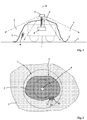
- an element 1 which is here a wheeled vehicle, positioned on the ground 2 of a field of operations.
- This vehicle 1 is equipped with a masking device according to the invention which comprises at least one flexible cover 3 having sufficient dimensions to cover the element 1.
- the cover 2 is made in the form of a multi-layered synthetic material fabric, for example a polyvinyl chloride (PVC) or polyethylene web, material comprising at least one R network of image generators at one of its layers, a network formed of a set of Reflecting or emitting points (or pixels) for a given radiation frequency, visible frequency (or color) or infrared frequency.
- a network of organic light-emitting diodes (OLEDs) may be deposited on a layer of the material.
- This OLED technology uses printing techniques and is particularly suitable for producing flexible emissive screens.
- the patent application US2012 / 0154196 describes by way of example such a flexible cover architecture for active camouflage. It is not necessary to describe it in more detail.
- An OLED network is an emissive image generator in the visible frequency domain.
- a network of thermal generators such as elements using the Peltier effect, that is to say that can be heated or cooled when they are traversed by a current of a given intensity.
- Patent applications US6927724 , WO2012169954 and WO2010093323 describe by way of example a masking device using a network of thermal generators.
- Such a network does not generate light but it reflects or absorbs light at certain frequencies (visible or infra red).
- the liquid crystals used to make such reflective gratings are well known in the field of electrophoretic displays and electronic inks. We can consider the patent application WO2004074911 which describes examples of materials.
- electrochromic grating technologies that are emissive or reflective in the infrared frequency domain.
- the patent application FR2969323 describes an example of a multilayer electrochromic device controllable in transmission or reflection.
- the resolution of the realized network will depend on the desired fineness for the masking. For example, a network comprising 2000 pixels per square meter may be provided.
- the network generating the cover 3 is connected to an image synthesizer 4 itself coupled to a camera 5.
- the camera 5 will be chosen according to the type or types of images generated by the network. If the coverage includes only one network operating in the visible range, the camera will operate in the visible frequency range. If the coverage includes a network operating in the infrared range, the camera used should be able to observe in the infrared range. Depending on the case it will be necessary to use several cameras, some for other visible frequencies for infrared frequencies. The cameras will be associated so that the same field of view is covered for all desired frequencies.
- the camera 5 is positioned so as to cover both a part of a background of the element (here a part of the ground 2) and all the cover 3.
- the camera 5 is here mounted on a vertical mat 6 secured to the element 1. It has a field of view 7 distributed 360 ° around a vertical axis 8.
- the field of vision 7 is delimited on the Figures 1 and 2 by dashed lines.
- Cameras with a 360 ° field of view are standard. They generally comprise several sensors regularly angularly distributed around the axis 8. Such a camera today has a relatively small size. It can be positioned above the cover 3 without constituting an object for the stealth camouflage achieved. To improve the camouflage, the housing enclosing the camera may also carry image generators connected to the image synthesizer 4.
- the synthesizer 4 is an electronic box that includes a computer that can analyze the images provided by the camera 5 and that can perform measurements on the images and in particular that can define, for different geometrical areas of the observed terrain, the contrast values (brightness differences or visible light intensity or thermal deviations) and possibly frequencies (visible or infrared).
- This calculator will include algorithms for comparing different parts of the received images and it will also include the means for controlling the image generators of the cover 3 (emissive, reflective or thermal generators).
- the synthesizer will control the image generators at a reference monochrome frequency value sufficiently contrasted with respect to the background. He will be able to order a white or black emission for example. Such a contrasting emission has been schematically figure 4a .
- the camera 5 which observes both the background (ground 2) and the cover 3 thus clearly marks the contour C of the cover 3.
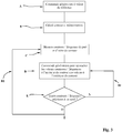
- the geometry of this contour C is then stored in the computer of the synthesizer 4 (FIG. step B). This will subsequently enable the synthesizer 4 to determine on the images that will be taken continuously by the camera 5 the frequency and contrast characteristics (thermal or visible) of the background 2 and those of the cover 3.
- the camera 5 supplies the synthesizer 4 with the images of the field 7 which is displayed ( figure 2 ).
- the computer of the synthesizer then goes (step C) to measure the parameters of contrast and possibly of frequencies on either side of the stored contour C.
- the calculator will measure the differences of colors (or frequencies) and also the differences of brightness (contrast between the colors on both sides of the contour).
- thermo contrast For the infrared range, a simple measure of brightness difference (thermal contrast) is generally sufficient to allow the control of thermal generators Peltier effect.
- This measurement is done with a certain resolution all along the contour C and on either side of the contour C on the whole of the field 7. It is shown schematically on the figure 2 three measurement intervals Z1, Z2 and Z3 along the contour C.
- the background 2 is indeed not necessarily identical all along the contour C. It is therefore necessary to define with some accuracy the contrast characteristics and possibly of necessary frequencies for the cover 3 all along the outline C.
- the device according to the invention can thus provide a masking which follows the characteristics of the ground.
- the cover can even adopt at a part of the contour the contrasts and possibly the frequencies associated with a vertical background, such as a wall or a building.
- the measurement resolution will be linked to that authorized by the camera 5 and to the dimensions of the element 1 (and the resolution of the network R carried by the cover 3).
- the synthesizer 4 controls (step D) the image generators of the cover 3 so that the contrasts (visible or thermal) and possibly the (visible) frequencies at each measurement zone Z1, Z2 ... Zi are, at the level of the coverage (thus inside the contour C), close to what is measured outside the contour C. It results schematized masking figure 4b .
- the synthesizer 4 thus works in differential mode and the adjustment is controlled by a test E for measuring the differences in contrast and possibly frequencies on either side of the contour C for each measurement zone Zi.
- a test E for measuring the differences in contrast and possibly frequencies on either side of the contour C for each measurement zone Zi.
- the control loop B1 drives the control until minimization of the deviations (output N of the test E).
- the loop B2 leads to a new measurement of contrast and possibly frequency on either side of the contour.
- the measurements can be carried out with a sampling frequency of 1 measurement per minute to 1 measurement per second according to the dynamic adaptation needs.
- the camouflage is thus fully adaptive and the appearance of the cover 3 follows over time the variations in brightness of the background 2.
- the camouflage can be fully operational at any time of the day by following in particular the variations in brightness and shadows due to the movement of the sun.
- the synthesizer 4 will control the image generators of the cover so as to give it an appearance in contrasts and possibly in frequencies having average values taking into account what is measured for the whole of the background 2 .
- the algorithm will, for example, be defined to minimize differences in contrast and possibly frequency when it is very close to the contour C, in order to reduce the differences at the edges of the cover.
- the algorithm will also be defined to take into account, at the level of the remainder of the coverage 3, and at a distance from the contour C, contrasts and possibly average frequencies calculated from the values measured on the background 2 at distances from the C contour more important.
- figure 4c an example of implementation in which the cover 3 partially covers a more contrasted area (bush or wall element).
- the camera detects during its analysis this contrast zone and the image generators of the cover 3 are controlled by the synthesizer so that they provide an image blurring the contour C and therefore corresponding to that of the zone 10.
- the synthesizer 4 will be programmed so that the image of the area 10 on the cover 3 extends over an average length of the same order as the length of this area viewed outside the outline C.
- the algorithm of The synthesizer calculates the average density of these points 9 in the background 2 and controls the generators of the cover 3 so that points 9 'of the same frequency (or color) are synthesized with an equivalent density.
- a coverage comprising several image generator networks: for example an active network in the visible domain and an active network in the infrared domain.
Landscapes
- Engineering & Computer Science (AREA)
- General Engineering & Computer Science (AREA)
- Multimedia (AREA)
- Signal Processing (AREA)
- Studio Devices (AREA)
- Transforming Light Signals Into Electric Signals (AREA)
- Closed-Circuit Television Systems (AREA)
- Image Analysis (AREA)
Claims (8)
- - Adaptatives Maskierungsverfahren für ein Element (1) in einem Einsatzgebiet (2), wobei man bei dem Verfahren mindestens eine Decke (3) benutzt, die es ermöglicht, das Element (1) zu bedecken, und die mindestens ein bilderzeugendes Netz (R) trägt, das mit einem Bildsynthetisiermittel (4) verbunden ist, das seinerseits an eine Kamera (5) gekoppelt ist, wobei das Verfahren dadurch gekennzeichnet ist, dass die Kamera (5) so positioniert ist, dass sie gleichzeitig einen Teil eines Hintergrunds (2) des Elements (1) und die gesamte Decke (3) abdeckt, wobei das Bildsynthetisiermittel (4) den Umriss der weichen Decke (3), die auf dem Element (1) abgelegt ist, im voraus bestimmt, und auf den Bildern, die kontinuierlich von der Kamera (5) aufgenommen werden, die Merkmale Frequenz und Kontrast des Hintergrunds (2) und diejenigen der Decke (3) bestimmt, wobei das Bildsynthetisiermittel (4) das oder die bilderzeugenden Netze (R) steuert, um den Kontrast zu minimalisieren und eventuell den Abstand von Frequenzen zwischen dem Hintergrund (2) und der Decke (3).
- - Adaptatives Maskierungsverfahren nach Anspruch 1, gekennzeichnet dadurch, dass, um den Kontrast und eventuell den Abstand von Frequenzen zwischen dem Hintergrund (2) und der Decke (3) zu minimalisieren, das Bildsynthetisiermittel (4) kontinuierlich einen Vergleich des Kontrasts und eventuell der Frequenz an beiden Seiten des Umrisses (C) verwirklicht, um die von dem oder den bilderzeugenden Netzen gelieferten Bilder zu steuern, in Kontrast und eventuell Frequenz, im Innern des Umrisses.
- - Adaptatives Maskierungsverfahren nach Anspruch 2, dadurch gekennzeichnet, dass man den Umriss (C) während der Platzierung der Decke (3) durch eine Steuerung aller Bildgeneratoren auf einen Bezugswert bestimmt.
- - Adaptatives Maskierungsverfahren nach einem der Ansprüche 1 bis 3, gekennzeichnet dadurch, dass die von der Kamera (5) aufgenommenen und von dem Synthesizer (4) erzeugten Bilder im sichtbaren und/oder Infrarot-Bereich liegen.
- - Adaptative Maskierungsvorrichtung für ein Element in einem Einsatzgebiet, wobei die Vorrichtung mindestens eine Decke (3) umfasst, die es ermöglicht, das Element (1) zu bedecken, und die mindestens ein bilderzeugendes Netz trägt, das mit einem Bildsynthetisiermittel (4) verbunden ist, das seinerseits an eine Kamera (5) gekoppelt ist, wobei die Vorrichtung dadurch gekennzeichnet ist, dass die Kamera (5) so positioniert ist, dass sie gleichzeitig einen Teil eines Hintergrunds (2) des Elements (1) und die gesamte Decke (3) abdeckt, wobei das Bildsynthetisiermittel (4) konfiguriert ist, um den Umriss der weichen Decke (3), die auf dem Element (1) abgelegt ist, im voraus zu bestimmen, und auf den Bildern, die kontinuierlich von der Kamera (5) aufgenommen werden, die Merkmale Frequenz und Kontrast des Hintergrunds (2) und diejenigen der Decke (3) zu bestimmen, wobei das Bildsynthetisiermittel (4) konfiguriert ist, um das oder die bilderzeugenden Netze zu steuern, um den Kontrast zu minimalisieren und eventuell den Abstand von Frequenzen zwischen dem Hintergrund (2) und der Decke (3).
- - Adaptative Maskierungsvorrichtung nach Anspruch 5, gekennzeichnet dadurch, dass die Kamera (5) ein 360°-Sichtfeld um eine senkrechte Achse (8) herum hat.
- - Adaptative Maskierungsvorrichtung nach einem der Ansprüche 5 oder 6, gekennzeichnet dadurch, dass sie ein im sichtbaren und/oder Infrarot-Bereich emittierendes bilderzeugendes Netz umfasst.
- - Adaptative Maskierungsvorrichtung nach einem der Ansprüche 5 bis 7, gekennzeichnet dadurch, dass sie ein im sichtbaren und/oder Infrarot-Bereich reflektierendes bilderzeugendes Netz umfasst.
Priority Applications (1)
| Application Number | Priority Date | Filing Date | Title |
|---|---|---|---|
| SI201430473T SI2992292T1 (en) | 2013-05-03 | 2014-05-02 | Adaptive masking process and device |
Applications Claiming Priority (2)
| Application Number | Priority Date | Filing Date | Title |
|---|---|---|---|
| FR1301053A FR3005350B1 (fr) | 2013-05-03 | 2013-05-03 | Procede et dispositif de masquage adaptatif. |
| PCT/FR2014/051049 WO2014177818A1 (fr) | 2013-05-03 | 2014-05-02 | Procede et dispositif de masquage adaptatif |
Publications (2)
| Publication Number | Publication Date |
|---|---|
| EP2992292A1 EP2992292A1 (de) | 2016-03-09 |
| EP2992292B1 true EP2992292B1 (de) | 2017-08-16 |
Family
ID=49510192
Family Applications (1)
| Application Number | Title | Priority Date | Filing Date |
|---|---|---|---|
| EP14729394.8A Active EP2992292B1 (de) | 2013-05-03 | 2014-05-02 | Adaptives maskierungsverfahren und vorrichtung |
Country Status (8)
| Country | Link |
|---|---|
| US (1) | US10048042B2 (de) |
| EP (1) | EP2992292B1 (de) |
| CA (1) | CA2908807C (de) |
| DK (1) | DK2992292T3 (de) |
| FR (1) | FR3005350B1 (de) |
| IL (1) | IL242338B (de) |
| SI (1) | SI2992292T1 (de) |
| WO (1) | WO2014177818A1 (de) |
Cited By (1)
| Publication number | Priority date | Publication date | Assignee | Title |
|---|---|---|---|---|
| RU224202U1 (ru) * | 2023-11-09 | 2024-03-19 | Федеральное Государственное Казенное Военное Образовательное Учреждение Высшего Образования "Военный Учебно-Научный Центр Сухопутных Войск "Общевойсковая Ордена Жукова Академия Вооруженных Сил Российской Федерации" | Комбинированное термостойкое радиопоглощающее покрытие |
Families Citing this family (5)
| Publication number | Priority date | Publication date | Assignee | Title |
|---|---|---|---|---|
| RU175328U1 (ru) * | 2016-10-28 | 2017-11-30 | Федеральное Государственное Казенное Военное Образовательное Учреждение Высшего Образования Военный Учебно-Научный Центр Сухопутных Войск "Общевойсковая Академия Вооруженных Сил Российской Федерации" | Индивидуальная деформирующая маска для подвижного объекта с адаптивной системой управления физическими параметрами маскировочного покрытия |
| RU189210U1 (ru) * | 2017-12-18 | 2019-05-16 | Федеральное государственное казенное военное образовательное учреждение высшего образования "ВОЕННАЯ АКАДЕМИЯ МАТЕРИАЛЬНО-ТЕХНИЧЕСКОГО ОБЕСПЕЧЕНИЯ имени генерала армии А.В. Хрулева" Министерства обороны Российской Федерации | Специальная система защиты полевого склада с потенциально опасными изделиями |
| RU193770U1 (ru) * | 2019-06-14 | 2019-11-14 | Федеральное Государственное Казенное Военное Образовательное Учреждение Высшего Образования Военный Учебно-Научный Центр Сухопутных Войск "Общевойсковая Академия Вооруженных Сил Российской Федерации" | Автоматизированная многоуровневая веерная деформирующая маска с имитацией силуэта подвижного объекта с видовыми признаками его неопределенности (энтропии) |
| FR3109219B1 (fr) | 2020-04-08 | 2024-03-29 | Nexter Systems | Dispositif de contrôle de la réflectivité infrarouge |
| RU206354U1 (ru) * | 2020-12-28 | 2021-09-07 | Федеральное Государственное Казенное Военное Образовательное Учреждение Высшего Образования "Военный Учебно-Научный Центр Сухопутных Войск "Общевойсковая Ордена Жукова Академия Вооруженных Сил Российской Федерации" | Маскировочное покрытие |
Family Cites Families (15)
| Publication number | Priority date | Publication date | Assignee | Title |
|---|---|---|---|---|
| US6466254B1 (en) * | 1997-05-08 | 2002-10-15 | Be Here Corporation | Method and apparatus for electronically distributing motion panoramic images |
| GB2362283B (en) * | 2000-04-07 | 2004-10-13 | Andrew James Hawke | Dynamically adaptive observability coatings (DAOC) system |
| GB2369421A (en) | 2000-11-10 | 2002-05-29 | Michael John Surtees | Camera-assisted camouflage device |
| US20020117605A1 (en) * | 2001-01-08 | 2002-08-29 | Alden Ray M. | Three-dimensional receiving and displaying process and apparatus with military application |
| US7038656B2 (en) | 2002-08-16 | 2006-05-02 | Sipix Imaging, Inc. | Electrophoretic display with dual-mode switching |
| US6927724B2 (en) | 2003-09-10 | 2005-08-09 | Alvin A. Snaper | Adaptive modification of surface properties to alter the perception of its underlying structure |
| DE102005044404A1 (de) * | 2005-09-21 | 2007-03-29 | Hörnicke, Christian | Aktiv adaptierendes visuelles Tarnsystem |
| US7999720B2 (en) * | 2006-02-13 | 2011-08-16 | The Invention Science Fund I, Llc | Camouflage positional elements |
| IL186320A (en) * | 2007-09-25 | 2014-09-30 | Eltics Ltd | Adjustable active thermal concealment system |
| US8077071B2 (en) | 2008-05-06 | 2011-12-13 | Military Wraps Research And Development, Inc. | Assemblies and systems for simultaneous multispectral adaptive camouflage, concealment, and deception |
| DE102008033464A1 (de) * | 2008-07-16 | 2010-01-21 | Heese, Werner, Dipl.-Ing. | Verfahren zum Unsichtbarmachen von Objekten |
| SE534185C2 (sv) | 2009-02-11 | 2011-05-24 | Bae Systems Haegglunds Ab | Anordning för termisk anpassning av en ytas temperaturfördelning |
| FR2969323B1 (fr) | 2010-12-15 | 2013-08-16 | Commissariat Energie Atomique | Dispositif electrochrome tout-solide, électrode bicouche pour ce dispositif, et procédé de préparation de ce dispositif. |
| SE536136C2 (sv) | 2011-06-07 | 2013-05-28 | Bae Systems Haegglunds Ab | Anordning och metod för signaturanpassning |
| US9175930B1 (en) | 2012-03-29 | 2015-11-03 | The United States Of America, As Represented By The Secretary Of The Navy | Adaptive electronic camouflage |
-
2013
- 2013-05-03 FR FR1301053A patent/FR3005350B1/fr not_active Expired - Fee Related
-
2014
- 2014-05-02 WO PCT/FR2014/051049 patent/WO2014177818A1/fr not_active Ceased
- 2014-05-02 DK DK14729394.8T patent/DK2992292T3/en active
- 2014-05-02 CA CA2908807A patent/CA2908807C/fr active Active
- 2014-05-02 SI SI201430473T patent/SI2992292T1/en unknown
- 2014-05-02 US US14/888,830 patent/US10048042B2/en active Active
- 2014-05-02 EP EP14729394.8A patent/EP2992292B1/de active Active
-
2015
- 2015-10-29 IL IL242338A patent/IL242338B/en active IP Right Grant
Non-Patent Citations (1)
| Title |
|---|
| None * |
Cited By (1)
| Publication number | Priority date | Publication date | Assignee | Title |
|---|---|---|---|---|
| RU224202U1 (ru) * | 2023-11-09 | 2024-03-19 | Федеральное Государственное Казенное Военное Образовательное Учреждение Высшего Образования "Военный Учебно-Научный Центр Сухопутных Войск "Общевойсковая Ордена Жукова Академия Вооруженных Сил Российской Федерации" | Комбинированное термостойкое радиопоглощающее покрытие |
Also Published As
| Publication number | Publication date |
|---|---|
| US10048042B2 (en) | 2018-08-14 |
| SI2992292T1 (en) | 2018-04-30 |
| EP2992292A1 (de) | 2016-03-09 |
| CA2908807A1 (fr) | 2014-11-06 |
| DK2992292T3 (en) | 2017-10-23 |
| FR3005350A1 (fr) | 2014-11-07 |
| WO2014177818A1 (fr) | 2014-11-06 |
| FR3005350B1 (fr) | 2015-04-17 |
| CA2908807C (fr) | 2019-06-11 |
| IL242338B (en) | 2019-06-30 |
| US20160076855A1 (en) | 2016-03-17 |
Similar Documents
| Publication | Publication Date | Title |
|---|---|---|
| EP2992292B1 (de) | Adaptives maskierungsverfahren und vorrichtung | |
| EP3206920B1 (de) | Vorrichtung zur aufnahme von bildern einer strassenszene für ein kraftfahrzeug | |
| EP3300942B1 (de) | Bildprojektionsverfahren mithilfe eines projektionssystems eines kraftfahrzeugs, und entsprechendes projektionssystem | |
| EP3049855B1 (de) | Datenanzeigebrillen mit blendschutzschild | |
| CA2793817C (en) | Method and apparatus for oil spill detection | |
| EP3049854B1 (de) | Datenanzeigebrillen mit blendschutzschild | |
| FR3100978A1 (fr) | Dispositif de fourniture d’informations de soudage | |
| FR3101002A1 (fr) | Appareil de fourniture d’informations de soudage ayant une fonction de détection d’environnement | |
| FR2908546A1 (fr) | Stereo camera intrusion detection system | |
| FR3007295A1 (fr) | Drone equipe d'un dispositif imageur et de moyens de protection du dispositif imageur | |
| WO2012127312A1 (fr) | Système de surveillance | |
| FR2982393A1 (fr) | Recherche d'une cible dans une image multispectrale | |
| KR200482197Y1 (ko) | 광학 박막 칼라 필터 및 오버랩을 통한 관찰 장치 | |
| FR2988334A1 (fr) | Procede et dispositif d'aide a la conduite diurne des vehicules automobiles | |
| FR3025323B1 (fr) | Systeme de finition active pour produire une image sur une surface | |
| WO2017068141A1 (fr) | Système adapté à fournir à un opérateur une visibilité augmentée et procédé associé | |
| WO2024052030A1 (fr) | Module lumineux à nappe de guidage flexible avec antenne intégrée | |
| FR3028051A1 (fr) | Systeme de visualisation stereoscopique a multiplexage de longueur d'onde actif | |
| FR2990279A1 (fr) | Systeme de visualisation porte par un mobile | |
| WO2022253587A1 (fr) | Capteur et procédé d'acquisition biométrique sans contact | |
| WO2015145032A1 (fr) | Dispositif d'imagerie et procede d'imagerie correspondant | |
| FR2772932A1 (fr) | Dispositif de selection de protections contre les rayonnements laser | |
| FR3011092A1 (fr) | Lunettes a affichage de donnees munies d'un ecran anti-eblouissement | |
| FR2924821A1 (fr) | Systeme d'imagerie. |
Legal Events
| Date | Code | Title | Description |
|---|---|---|---|
| PUAI | Public reference made under article 153(3) epc to a published international application that has entered the european phase |
Free format text: ORIGINAL CODE: 0009012 |
|
| 17P | Request for examination filed |
Effective date: 20151124 |
|
| AK | Designated contracting states |
Kind code of ref document: A1 Designated state(s): AL AT BE BG CH CY CZ DE DK EE ES FI FR GB GR HR HU IE IS IT LI LT LU LV MC MK MT NL NO PL PT RO RS SE SI SK SM TR |
|
| AX | Request for extension of the european patent |
Extension state: BA ME |
|
| DAX | Request for extension of the european patent (deleted) | ||
| GRAP | Despatch of communication of intention to grant a patent |
Free format text: ORIGINAL CODE: EPIDOSNIGR1 |
|
| INTG | Intention to grant announced |
Effective date: 20170307 |
|
| GRAS | Grant fee paid |
Free format text: ORIGINAL CODE: EPIDOSNIGR3 |
|
| GRAA | (expected) grant |
Free format text: ORIGINAL CODE: 0009210 |
|
| AK | Designated contracting states |
Kind code of ref document: B1 Designated state(s): AL AT BE BG CH CY CZ DE DK EE ES FI FR GB GR HR HU IE IS IT LI LT LU LV MC MK MT NL NO PL PT RO RS SE SI SK SM TR |
|
| REG | Reference to a national code |
Ref country code: GB Ref legal event code: FG4D Free format text: NOT ENGLISH |
|
| REG | Reference to a national code |
Ref country code: CH Ref legal event code: EP |
|
| REG | Reference to a national code |
Ref country code: IE Ref legal event code: FG4D Free format text: LANGUAGE OF EP DOCUMENT: FRENCH |
|
| REG | Reference to a national code |
Ref country code: AT Ref legal event code: REF Ref document number: 919482 Country of ref document: AT Kind code of ref document: T Effective date: 20170915 |
|
| REG | Reference to a national code |
Ref country code: DE Ref legal event code: R096 Ref document number: 602014013221 Country of ref document: DE |
|
| REG | Reference to a national code |
Ref country code: DK Ref legal event code: T3 Effective date: 20171016 |
|
| REG | Reference to a national code |
Ref country code: SE Ref legal event code: TRGR |
|
| REG | Reference to a national code |
Ref country code: NL Ref legal event code: MP Effective date: 20170816 |
|
| REG | Reference to a national code |
Ref country code: LT Ref legal event code: MG4D |
|
| REG | Reference to a national code |
Ref country code: AT Ref legal event code: MK05 Ref document number: 919482 Country of ref document: AT Kind code of ref document: T Effective date: 20170816 |
|
| PG25 | Lapsed in a contracting state [announced via postgrant information from national office to epo] |
Ref country code: FI Free format text: LAPSE BECAUSE OF FAILURE TO SUBMIT A TRANSLATION OF THE DESCRIPTION OR TO PAY THE FEE WITHIN THE PRESCRIBED TIME-LIMIT Effective date: 20170816 Ref country code: NL Free format text: LAPSE BECAUSE OF FAILURE TO SUBMIT A TRANSLATION OF THE DESCRIPTION OR TO PAY THE FEE WITHIN THE PRESCRIBED TIME-LIMIT Effective date: 20170816 Ref country code: AT Free format text: LAPSE BECAUSE OF FAILURE TO SUBMIT A TRANSLATION OF THE DESCRIPTION OR TO PAY THE FEE WITHIN THE PRESCRIBED TIME-LIMIT Effective date: 20170816 Ref country code: NO Free format text: LAPSE BECAUSE OF FAILURE TO SUBMIT A TRANSLATION OF THE DESCRIPTION OR TO PAY THE FEE WITHIN THE PRESCRIBED TIME-LIMIT Effective date: 20171116 Ref country code: LT Free format text: LAPSE BECAUSE OF FAILURE TO SUBMIT A TRANSLATION OF THE DESCRIPTION OR TO PAY THE FEE WITHIN THE PRESCRIBED TIME-LIMIT Effective date: 20170816 |
|
| PG25 | Lapsed in a contracting state [announced via postgrant information from national office to epo] |
Ref country code: IS Free format text: LAPSE BECAUSE OF FAILURE TO SUBMIT A TRANSLATION OF THE DESCRIPTION OR TO PAY THE FEE WITHIN THE PRESCRIBED TIME-LIMIT Effective date: 20171216 Ref country code: LV Free format text: LAPSE BECAUSE OF FAILURE TO SUBMIT A TRANSLATION OF THE DESCRIPTION OR TO PAY THE FEE WITHIN THE PRESCRIBED TIME-LIMIT Effective date: 20170816 Ref country code: GR Free format text: LAPSE BECAUSE OF FAILURE TO SUBMIT A TRANSLATION OF THE DESCRIPTION OR TO PAY THE FEE WITHIN THE PRESCRIBED TIME-LIMIT Effective date: 20171117 Ref country code: RS Free format text: LAPSE BECAUSE OF FAILURE TO SUBMIT A TRANSLATION OF THE DESCRIPTION OR TO PAY THE FEE WITHIN THE PRESCRIBED TIME-LIMIT Effective date: 20170816 Ref country code: BG Free format text: LAPSE BECAUSE OF FAILURE TO SUBMIT A TRANSLATION OF THE DESCRIPTION OR TO PAY THE FEE WITHIN THE PRESCRIBED TIME-LIMIT Effective date: 20171116 Ref country code: PL Free format text: LAPSE BECAUSE OF FAILURE TO SUBMIT A TRANSLATION OF THE DESCRIPTION OR TO PAY THE FEE WITHIN THE PRESCRIBED TIME-LIMIT Effective date: 20170816 Ref country code: ES Free format text: LAPSE BECAUSE OF FAILURE TO SUBMIT A TRANSLATION OF THE DESCRIPTION OR TO PAY THE FEE WITHIN THE PRESCRIBED TIME-LIMIT Effective date: 20170816 |
|
| REG | Reference to a national code |
Ref country code: FR Ref legal event code: PLFP Year of fee payment: 5 |
|
| PG25 | Lapsed in a contracting state [announced via postgrant information from national office to epo] |
Ref country code: CZ Free format text: LAPSE BECAUSE OF FAILURE TO SUBMIT A TRANSLATION OF THE DESCRIPTION OR TO PAY THE FEE WITHIN THE PRESCRIBED TIME-LIMIT Effective date: 20170816 Ref country code: RO Free format text: LAPSE BECAUSE OF FAILURE TO SUBMIT A TRANSLATION OF THE DESCRIPTION OR TO PAY THE FEE WITHIN THE PRESCRIBED TIME-LIMIT Effective date: 20170816 |
|
| REG | Reference to a national code |
Ref country code: DE Ref legal event code: R097 Ref document number: 602014013221 Country of ref document: DE |
|
| PG25 | Lapsed in a contracting state [announced via postgrant information from national office to epo] |
Ref country code: SK Free format text: LAPSE BECAUSE OF FAILURE TO SUBMIT A TRANSLATION OF THE DESCRIPTION OR TO PAY THE FEE WITHIN THE PRESCRIBED TIME-LIMIT Effective date: 20170816 Ref country code: EE Free format text: LAPSE BECAUSE OF FAILURE TO SUBMIT A TRANSLATION OF THE DESCRIPTION OR TO PAY THE FEE WITHIN THE PRESCRIBED TIME-LIMIT Effective date: 20170816 Ref country code: IT Free format text: LAPSE BECAUSE OF FAILURE TO SUBMIT A TRANSLATION OF THE DESCRIPTION OR TO PAY THE FEE WITHIN THE PRESCRIBED TIME-LIMIT Effective date: 20170816 Ref country code: SM Free format text: LAPSE BECAUSE OF FAILURE TO SUBMIT A TRANSLATION OF THE DESCRIPTION OR TO PAY THE FEE WITHIN THE PRESCRIBED TIME-LIMIT Effective date: 20170816 |
|
| PLBE | No opposition filed within time limit |
Free format text: ORIGINAL CODE: 0009261 |
|
| STAA | Information on the status of an ep patent application or granted ep patent |
Free format text: STATUS: NO OPPOSITION FILED WITHIN TIME LIMIT |
|
| 26N | No opposition filed |
Effective date: 20180517 |
|
| PG25 | Lapsed in a contracting state [announced via postgrant information from national office to epo] |
Ref country code: MT Free format text: LAPSE BECAUSE OF FAILURE TO SUBMIT A TRANSLATION OF THE DESCRIPTION OR TO PAY THE FEE WITHIN THE PRESCRIBED TIME-LIMIT Effective date: 20170816 |
|
| REG | Reference to a national code |
Ref country code: CH Ref legal event code: PL |
|
| REG | Reference to a national code |
Ref country code: BE Ref legal event code: MM Effective date: 20180531 |
|
| PG25 | Lapsed in a contracting state [announced via postgrant information from national office to epo] |
Ref country code: MC Free format text: LAPSE BECAUSE OF FAILURE TO SUBMIT A TRANSLATION OF THE DESCRIPTION OR TO PAY THE FEE WITHIN THE PRESCRIBED TIME-LIMIT Effective date: 20170816 |
|
| REG | Reference to a national code |
Ref country code: IE Ref legal event code: MM4A |
|
| PG25 | Lapsed in a contracting state [announced via postgrant information from national office to epo] |
Ref country code: LI Free format text: LAPSE BECAUSE OF NON-PAYMENT OF DUE FEES Effective date: 20180531 Ref country code: CH Free format text: LAPSE BECAUSE OF NON-PAYMENT OF DUE FEES Effective date: 20180531 |
|
| PG25 | Lapsed in a contracting state [announced via postgrant information from national office to epo] |
Ref country code: LU Free format text: LAPSE BECAUSE OF NON-PAYMENT OF DUE FEES Effective date: 20180502 |
|
| PG25 | Lapsed in a contracting state [announced via postgrant information from national office to epo] |
Ref country code: IE Free format text: LAPSE BECAUSE OF NON-PAYMENT OF DUE FEES Effective date: 20180502 |
|
| PG25 | Lapsed in a contracting state [announced via postgrant information from national office to epo] |
Ref country code: BE Free format text: LAPSE BECAUSE OF NON-PAYMENT OF DUE FEES Effective date: 20180531 |
|
| PG25 | Lapsed in a contracting state [announced via postgrant information from national office to epo] |
Ref country code: TR Free format text: LAPSE BECAUSE OF FAILURE TO SUBMIT A TRANSLATION OF THE DESCRIPTION OR TO PAY THE FEE WITHIN THE PRESCRIBED TIME-LIMIT Effective date: 20170816 |
|
| PG25 | Lapsed in a contracting state [announced via postgrant information from national office to epo] |
Ref country code: PT Free format text: LAPSE BECAUSE OF FAILURE TO SUBMIT A TRANSLATION OF THE DESCRIPTION OR TO PAY THE FEE WITHIN THE PRESCRIBED TIME-LIMIT Effective date: 20170816 |
|
| PG25 | Lapsed in a contracting state [announced via postgrant information from national office to epo] |
Ref country code: MK Free format text: LAPSE BECAUSE OF NON-PAYMENT OF DUE FEES Effective date: 20170816 Ref country code: HU Free format text: LAPSE BECAUSE OF FAILURE TO SUBMIT A TRANSLATION OF THE DESCRIPTION OR TO PAY THE FEE WITHIN THE PRESCRIBED TIME-LIMIT; INVALID AB INITIO Effective date: 20140502 Ref country code: CY Free format text: LAPSE BECAUSE OF FAILURE TO SUBMIT A TRANSLATION OF THE DESCRIPTION OR TO PAY THE FEE WITHIN THE PRESCRIBED TIME-LIMIT Effective date: 20170816 Ref country code: HR Free format text: LAPSE BECAUSE OF FAILURE TO SUBMIT A TRANSLATION OF THE DESCRIPTION OR TO PAY THE FEE WITHIN THE PRESCRIBED TIME-LIMIT Effective date: 20170816 |
|
| PG25 | Lapsed in a contracting state [announced via postgrant information from national office to epo] |
Ref country code: AL Free format text: LAPSE BECAUSE OF FAILURE TO SUBMIT A TRANSLATION OF THE DESCRIPTION OR TO PAY THE FEE WITHIN THE PRESCRIBED TIME-LIMIT Effective date: 20170816 |
|
| PGFP | Annual fee paid to national office [announced via postgrant information from national office to epo] |
Ref country code: DE Payment date: 20250423 Year of fee payment: 12 |
|
| PGFP | Annual fee paid to national office [announced via postgrant information from national office to epo] |
Ref country code: GB Payment date: 20250423 Year of fee payment: 12 Ref country code: DK Payment date: 20250423 Year of fee payment: 12 |
|
| PGFP | Annual fee paid to national office [announced via postgrant information from national office to epo] |
Ref country code: FR Payment date: 20250423 Year of fee payment: 12 |
|
| PGFP | Annual fee paid to national office [announced via postgrant information from national office to epo] |
Ref country code: SE Payment date: 20250423 Year of fee payment: 12 Ref country code: SI Payment date: 20250429 Year of fee payment: 12 |