EP2992268B1 - Process and plant for separating heavy metals from phosphorus-containing starting material - Google Patents
Process and plant for separating heavy metals from phosphorus-containing starting material Download PDFInfo
- Publication number
- EP2992268B1 EP2992268B1 EP13722355.8A EP13722355A EP2992268B1 EP 2992268 B1 EP2992268 B1 EP 2992268B1 EP 13722355 A EP13722355 A EP 13722355A EP 2992268 B1 EP2992268 B1 EP 2992268B1
- Authority
- EP
- European Patent Office
- Prior art keywords
- reactor
- starting material
- process according
- alkaline source
- heated
- Prior art date
- Legal status (The legal status is an assumption and is not a legal conclusion. Google has not performed a legal analysis and makes no representation as to the accuracy of the status listed.)
- Active
Links
- 238000000034 method Methods 0.000 title claims description 38
- 239000007858 starting material Substances 0.000 title claims description 36
- 229910001385 heavy metal Inorganic materials 0.000 title claims description 21
- 239000011574 phosphorus Substances 0.000 title description 20
- 229910052698 phosphorus Inorganic materials 0.000 title description 20
- OAICVXFJPJFONN-UHFFFAOYSA-N Phosphorus Chemical compound [P] OAICVXFJPJFONN-UHFFFAOYSA-N 0.000 title description 19
- 239000007789 gas Substances 0.000 claims description 22
- CDBYLPFSWZWCQE-UHFFFAOYSA-L sodium carbonate Substances [Na+].[Na+].[O-]C([O-])=O CDBYLPFSWZWCQE-UHFFFAOYSA-L 0.000 claims description 19
- 229910052799 carbon Inorganic materials 0.000 claims description 16
- 239000000567 combustion gas Substances 0.000 claims description 16
- 239000010801 sewage sludge Substances 0.000 claims description 16
- 238000010438 heat treatment Methods 0.000 claims description 15
- OKTJSMMVPCPJKN-UHFFFAOYSA-N Carbon Chemical compound [C] OKTJSMMVPCPJKN-UHFFFAOYSA-N 0.000 claims description 13
- 239000002028 Biomass Substances 0.000 claims description 7
- 229910000029 sodium carbonate Inorganic materials 0.000 claims description 7
- 235000017550 sodium carbonate Nutrition 0.000 claims description 5
- BWHMMNNQKKPAPP-UHFFFAOYSA-L potassium carbonate Substances [K+].[K+].[O-]C([O-])=O BWHMMNNQKKPAPP-UHFFFAOYSA-L 0.000 claims description 4
- 150000002736 metal compounds Chemical class 0.000 claims description 3
- KWYUFKZDYYNOTN-UHFFFAOYSA-M Potassium hydroxide Chemical class [OH-].[K+] KWYUFKZDYYNOTN-UHFFFAOYSA-M 0.000 claims description 2
- HEMHJVSKTPXQMS-UHFFFAOYSA-M Sodium hydroxide Chemical class [OH-].[Na+] HEMHJVSKTPXQMS-UHFFFAOYSA-M 0.000 claims description 2
- 239000003245 coal Substances 0.000 claims description 2
- 239000000571 coke Substances 0.000 claims description 2
- 238000009833 condensation Methods 0.000 claims description 2
- 230000005494 condensation Effects 0.000 claims description 2
- 239000003077 lignite Substances 0.000 claims description 2
- 235000011181 potassium carbonates Nutrition 0.000 claims description 2
- 235000011118 potassium hydroxide Nutrition 0.000 claims description 2
- 238000001556 precipitation Methods 0.000 claims description 2
- 235000011182 sodium carbonates Nutrition 0.000 claims description 2
- 235000011121 sodium hydroxide Nutrition 0.000 claims description 2
- 239000003337 fertilizer Substances 0.000 description 18
- 239000000047 product Substances 0.000 description 15
- 241000196324 Embryophyta Species 0.000 description 13
- 239000002956 ash Substances 0.000 description 11
- 239000007787 solid Substances 0.000 description 11
- 229910019142 PO4 Inorganic materials 0.000 description 6
- 239000000446 fuel Substances 0.000 description 6
- VNWKTOKETHGBQD-UHFFFAOYSA-N methane Chemical compound C VNWKTOKETHGBQD-UHFFFAOYSA-N 0.000 description 6
- 235000015097 nutrients Nutrition 0.000 description 6
- NBIIXXVUZAFLBC-UHFFFAOYSA-K phosphate Chemical compound [O-]P([O-])([O-])=O NBIIXXVUZAFLBC-UHFFFAOYSA-K 0.000 description 6
- 239000010452 phosphate Substances 0.000 description 6
- DLYUQMMRRRQYAE-UHFFFAOYSA-N tetraphosphorus decaoxide Chemical compound O1P(O2)(=O)OP3(=O)OP1(=O)OP2(=O)O3 DLYUQMMRRRQYAE-UHFFFAOYSA-N 0.000 description 6
- 239000000203 mixture Substances 0.000 description 5
- 235000002918 Fraxinus excelsior Nutrition 0.000 description 4
- 239000000428 dust Substances 0.000 description 4
- 238000004519 manufacturing process Methods 0.000 description 4
- 239000000463 material Substances 0.000 description 4
- VYPSYNLAJGMNEJ-UHFFFAOYSA-N Silicium dioxide Chemical compound O=[Si]=O VYPSYNLAJGMNEJ-UHFFFAOYSA-N 0.000 description 3
- 229910052793 cadmium Inorganic materials 0.000 description 3
- BDOSMKKIYDKNTQ-UHFFFAOYSA-N cadmium atom Chemical compound [Cd] BDOSMKKIYDKNTQ-UHFFFAOYSA-N 0.000 description 3
- 239000000969 carrier Substances 0.000 description 3
- 238000006243 chemical reaction Methods 0.000 description 3
- 239000003345 natural gas Substances 0.000 description 3
- 239000002686 phosphate fertilizer Substances 0.000 description 3
- 239000002367 phosphate rock Substances 0.000 description 3
- 150000003013 phosphoric acid derivatives Chemical class 0.000 description 3
- 239000002994 raw material Substances 0.000 description 3
- 239000011343 solid material Substances 0.000 description 3
- OYPRJOBELJOOCE-UHFFFAOYSA-N Calcium Chemical compound [Ca] OYPRJOBELJOOCE-UHFFFAOYSA-N 0.000 description 2
- VTYYLEPIZMXCLO-UHFFFAOYSA-L Calcium carbonate Chemical compound [Ca+2].[O-]C([O-])=O VTYYLEPIZMXCLO-UHFFFAOYSA-L 0.000 description 2
- XEEYBQQBJWHFJM-UHFFFAOYSA-N Iron Chemical compound [Fe] XEEYBQQBJWHFJM-UHFFFAOYSA-N 0.000 description 2
- PXHVJJICTQNCMI-UHFFFAOYSA-N Nickel Chemical compound [Ni] PXHVJJICTQNCMI-UHFFFAOYSA-N 0.000 description 2
- NBIIXXVUZAFLBC-UHFFFAOYSA-N Phosphoric acid Chemical compound OP(O)(O)=O NBIIXXVUZAFLBC-UHFFFAOYSA-N 0.000 description 2
- WCUXLLCKKVVCTQ-UHFFFAOYSA-M Potassium chloride Chemical compound [Cl-].[K+] WCUXLLCKKVVCTQ-UHFFFAOYSA-M 0.000 description 2
- UIIMBOGNXHQVGW-UHFFFAOYSA-M Sodium bicarbonate Chemical compound [Na+].OC([O-])=O UIIMBOGNXHQVGW-UHFFFAOYSA-M 0.000 description 2
- QAOWNCQODCNURD-UHFFFAOYSA-N Sulfuric acid Chemical compound OS(O)(=O)=O QAOWNCQODCNURD-UHFFFAOYSA-N 0.000 description 2
- 229910052770 Uranium Inorganic materials 0.000 description 2
- 239000011230 binding agent Substances 0.000 description 2
- 239000011575 calcium Substances 0.000 description 2
- 229910052791 calcium Inorganic materials 0.000 description 2
- 150000003841 chloride salts Chemical class 0.000 description 2
- 239000011248 coating agent Substances 0.000 description 2
- 150000001875 compounds Chemical class 0.000 description 2
- 239000012467 final product Substances 0.000 description 2
- 239000008187 granular material Substances 0.000 description 2
- BHEPBYXIRTUNPN-UHFFFAOYSA-N hydridophosphorus(.) (triplet) Chemical compound [PH] BHEPBYXIRTUNPN-UHFFFAOYSA-N 0.000 description 2
- 229910052500 inorganic mineral Inorganic materials 0.000 description 2
- 235000010755 mineral Nutrition 0.000 description 2
- 239000011707 mineral Substances 0.000 description 2
- 239000002245 particle Substances 0.000 description 2
- 238000011084 recovery Methods 0.000 description 2
- 238000000926 separation method Methods 0.000 description 2
- 239000000126 substance Substances 0.000 description 2
- 239000002426 superphosphate Substances 0.000 description 2
- DNYWZCXLKNTFFI-UHFFFAOYSA-N uranium Chemical compound [U][U][U][U][U][U][U][U][U][U][U][U][U][U][U][U][U][U][U][U][U][U][U][U][U][U][U][U][U][U][U][U][U][U][U][U][U][U][U][U][U][U][U][U][U][U][U][U][U][U][U][U][U][U][U][U][U][U][U][U][U][U][U][U][U][U][U][U][U][U][U][U][U][U][U][U][U][U][U][U][U][U][U][U][U][U][U][U][U][U][U][U][U][U][U][U][U][U][U][U][U][U][U][U][U][U][U][U][U][U][U][U][U][U] DNYWZCXLKNTFFI-UHFFFAOYSA-N 0.000 description 2
- 239000002699 waste material Substances 0.000 description 2
- XLYOFNOQVPJJNP-UHFFFAOYSA-N water Substances O XLYOFNOQVPJJNP-UHFFFAOYSA-N 0.000 description 2
- UGFAIRIUMAVXCW-UHFFFAOYSA-N Carbon monoxide Chemical compound [O+]#[C-] UGFAIRIUMAVXCW-UHFFFAOYSA-N 0.000 description 1
- BVKZGUZCCUSVTD-UHFFFAOYSA-L Carbonate Chemical compound [O-]C([O-])=O BVKZGUZCCUSVTD-UHFFFAOYSA-L 0.000 description 1
- VYZAMTAEIAYCRO-UHFFFAOYSA-N Chromium Chemical compound [Cr] VYZAMTAEIAYCRO-UHFFFAOYSA-N 0.000 description 1
- RYGMFSIKBFXOCR-UHFFFAOYSA-N Copper Chemical compound [Cu] RYGMFSIKBFXOCR-UHFFFAOYSA-N 0.000 description 1
- DGAQECJNVWCQMB-PUAWFVPOSA-M Ilexoside XXIX Chemical compound C[C@@H]1CC[C@@]2(CC[C@@]3(C(=CC[C@H]4[C@]3(CC[C@@H]5[C@@]4(CC[C@@H](C5(C)C)OS(=O)(=O)[O-])C)C)[C@@H]2[C@]1(C)O)C)C(=O)O[C@H]6[C@@H]([C@H]([C@@H]([C@H](O6)CO)O)O)O.[Na+] DGAQECJNVWCQMB-PUAWFVPOSA-M 0.000 description 1
- KKCBUQHMOMHUOY-UHFFFAOYSA-N Na2O Inorganic materials [O-2].[Na+].[Na+] KKCBUQHMOMHUOY-UHFFFAOYSA-N 0.000 description 1
- XUIMIQQOPSSXEZ-UHFFFAOYSA-N Silicon Chemical compound [Si] XUIMIQQOPSSXEZ-UHFFFAOYSA-N 0.000 description 1
- 240000008042 Zea mays Species 0.000 description 1
- 235000005824 Zea mays ssp. parviglumis Nutrition 0.000 description 1
- 235000002017 Zea mays subsp mays Nutrition 0.000 description 1
- HCHKCACWOHOZIP-UHFFFAOYSA-N Zinc Chemical compound [Zn] HCHKCACWOHOZIP-UHFFFAOYSA-N 0.000 description 1
- AZDRQVAHHNSJOQ-UHFFFAOYSA-N alumane Chemical class [AlH3] AZDRQVAHHNSJOQ-UHFFFAOYSA-N 0.000 description 1
- PNEYBMLMFCGWSK-UHFFFAOYSA-N aluminium oxide Inorganic materials [O-2].[O-2].[O-2].[Al+3].[Al+3] PNEYBMLMFCGWSK-UHFFFAOYSA-N 0.000 description 1
- 229910000147 aluminium phosphate Inorganic materials 0.000 description 1
- BFNBIHQBYMNNAN-UHFFFAOYSA-N ammonium sulfate Chemical compound N.N.OS(O)(=O)=O BFNBIHQBYMNNAN-UHFFFAOYSA-N 0.000 description 1
- 229910052921 ammonium sulfate Inorganic materials 0.000 description 1
- 235000011130 ammonium sulphate Nutrition 0.000 description 1
- 229910052785 arsenic Inorganic materials 0.000 description 1
- RQNWIZPPADIBDY-UHFFFAOYSA-N arsenic atom Chemical compound [As] RQNWIZPPADIBDY-UHFFFAOYSA-N 0.000 description 1
- 230000015572 biosynthetic process Effects 0.000 description 1
- 239000013590 bulk material Substances 0.000 description 1
- 239000006227 byproduct Substances 0.000 description 1
- 229910000019 calcium carbonate Inorganic materials 0.000 description 1
- 235000010216 calcium carbonate Nutrition 0.000 description 1
- AXCZMVOFGPJBDE-UHFFFAOYSA-L calcium dihydroxide Chemical compound [OH-].[OH-].[Ca+2] AXCZMVOFGPJBDE-UHFFFAOYSA-L 0.000 description 1
- 239000000920 calcium hydroxide Substances 0.000 description 1
- 235000011116 calcium hydroxide Nutrition 0.000 description 1
- ODINCKMPIJJUCX-UHFFFAOYSA-N calcium oxide Inorganic materials [Ca]=O ODINCKMPIJJUCX-UHFFFAOYSA-N 0.000 description 1
- 238000001311 chemical methods and process Methods 0.000 description 1
- 238000004140 cleaning Methods 0.000 description 1
- 229910052681 coesite Inorganic materials 0.000 description 1
- 238000002485 combustion reaction Methods 0.000 description 1
- 229910052802 copper Inorganic materials 0.000 description 1
- 239000010949 copper Substances 0.000 description 1
- 235000005822 corn Nutrition 0.000 description 1
- 229910052593 corundum Inorganic materials 0.000 description 1
- 229910052906 cristobalite Inorganic materials 0.000 description 1
- 238000000354 decomposition reaction Methods 0.000 description 1
- 238000010586 diagram Methods 0.000 description 1
- 238000009826 distribution Methods 0.000 description 1
- 238000005367 electrostatic precipitation Methods 0.000 description 1
- 239000012717 electrostatic precipitator Substances 0.000 description 1
- 230000008030 elimination Effects 0.000 description 1
- 238000003379 elimination reaction Methods 0.000 description 1
- 238000005516 engineering process Methods 0.000 description 1
- 210000003608 fece Anatomy 0.000 description 1
- 239000003546 flue gas Substances 0.000 description 1
- 235000013305 food Nutrition 0.000 description 1
- 229910052739 hydrogen Inorganic materials 0.000 description 1
- 239000001257 hydrogen Substances 0.000 description 1
- -1 hydrogen anion Chemical class 0.000 description 1
- 150000002500 ions Chemical class 0.000 description 1
- 229910052742 iron Inorganic materials 0.000 description 1
- JEIPFZHSYJVQDO-UHFFFAOYSA-N iron(III) oxide Inorganic materials O=[Fe]O[Fe]=O JEIPFZHSYJVQDO-UHFFFAOYSA-N 0.000 description 1
- 239000010871 livestock manure Substances 0.000 description 1
- 238000002844 melting Methods 0.000 description 1
- 230000008018 melting Effects 0.000 description 1
- QSHDDOUJBYECFT-UHFFFAOYSA-N mercury Chemical compound [Hg] QSHDDOUJBYECFT-UHFFFAOYSA-N 0.000 description 1
- 229910052753 mercury Inorganic materials 0.000 description 1
- 229910052751 metal Inorganic materials 0.000 description 1
- 239000002184 metal Substances 0.000 description 1
- 150000002739 metals Chemical class 0.000 description 1
- 238000002156 mixing Methods 0.000 description 1
- 229910052759 nickel Inorganic materials 0.000 description 1
- 235000016709 nutrition Nutrition 0.000 description 1
- 230000035764 nutrition Effects 0.000 description 1
- 238000009329 organic farming Methods 0.000 description 1
- 239000002957 persistent organic pollutant Substances 0.000 description 1
- 230000029553 photosynthesis Effects 0.000 description 1
- 238000010672 photosynthesis Methods 0.000 description 1
- 231100000614 poison Toxicity 0.000 description 1
- 239000001103 potassium chloride Substances 0.000 description 1
- 235000011164 potassium chloride Nutrition 0.000 description 1
- OTYBMLCTZGSZBG-UHFFFAOYSA-L potassium sulfate Chemical compound [K+].[K+].[O-]S([O-])(=O)=O OTYBMLCTZGSZBG-UHFFFAOYSA-L 0.000 description 1
- 229910052939 potassium sulfate Inorganic materials 0.000 description 1
- 235000011151 potassium sulphates Nutrition 0.000 description 1
- 239000000843 powder Substances 0.000 description 1
- 238000004064 recycling Methods 0.000 description 1
- 239000004576 sand Substances 0.000 description 1
- 239000010703 silicon Substances 0.000 description 1
- 229910052710 silicon Inorganic materials 0.000 description 1
- 239000000377 silicon dioxide Substances 0.000 description 1
- 239000002893 slag Substances 0.000 description 1
- 239000011734 sodium Substances 0.000 description 1
- 229910052708 sodium Inorganic materials 0.000 description 1
- 235000017557 sodium bicarbonate Nutrition 0.000 description 1
- 229910000030 sodium bicarbonate Inorganic materials 0.000 description 1
- 239000002594 sorbent Substances 0.000 description 1
- 238000001179 sorption measurement Methods 0.000 description 1
- 229910052682 stishovite Inorganic materials 0.000 description 1
- 238000003860 storage Methods 0.000 description 1
- 231100000331 toxic Toxicity 0.000 description 1
- 230000002588 toxic effect Effects 0.000 description 1
- 239000003440 toxic substance Substances 0.000 description 1
- 229910052905 tridymite Inorganic materials 0.000 description 1
- 229910001845 yogo sapphire Inorganic materials 0.000 description 1
- 229910052725 zinc Inorganic materials 0.000 description 1
- 239000011701 zinc Substances 0.000 description 1
Images
Classifications
-
- F—MECHANICAL ENGINEERING; LIGHTING; HEATING; WEAPONS; BLASTING
- F23—COMBUSTION APPARATUS; COMBUSTION PROCESSES
- F23G—CREMATION FURNACES; CONSUMING WASTE PRODUCTS BY COMBUSTION
- F23G5/00—Incineration of waste; Incinerator constructions; Details, accessories or control therefor
- F23G5/02—Incineration of waste; Incinerator constructions; Details, accessories or control therefor with pretreatment
-
- B—PERFORMING OPERATIONS; TRANSPORTING
- B01—PHYSICAL OR CHEMICAL PROCESSES OR APPARATUS IN GENERAL
- B01J—CHEMICAL OR PHYSICAL PROCESSES, e.g. CATALYSIS OR COLLOID CHEMISTRY; THEIR RELEVANT APPARATUS
- B01J8/00—Chemical or physical processes in general, conducted in the presence of fluids and solid particles; Apparatus for such processes
- B01J8/18—Chemical or physical processes in general, conducted in the presence of fluids and solid particles; Apparatus for such processes with fluidised particles
- B01J8/24—Chemical or physical processes in general, conducted in the presence of fluids and solid particles; Apparatus for such processes with fluidised particles according to "fluidised-bed" technique
-
- C—CHEMISTRY; METALLURGY
- C01—INORGANIC CHEMISTRY
- C01B—NON-METALLIC ELEMENTS; COMPOUNDS THEREOF; METALLOIDS OR COMPOUNDS THEREOF NOT COVERED BY SUBCLASS C01C
- C01B25/00—Phosphorus; Compounds thereof
- C01B25/16—Oxyacids of phosphorus; Salts thereof
- C01B25/26—Phosphates
- C01B25/265—General methods for obtaining phosphates
-
- C—CHEMISTRY; METALLURGY
- C05—FERTILISERS; MANUFACTURE THEREOF
- C05B—PHOSPHATIC FERTILISERS
- C05B17/00—Other phosphatic fertilisers, e.g. soft rock phosphates, bone meal
-
- F—MECHANICAL ENGINEERING; LIGHTING; HEATING; WEAPONS; BLASTING
- F23—COMBUSTION APPARATUS; COMBUSTION PROCESSES
- F23G—CREMATION FURNACES; CONSUMING WASTE PRODUCTS BY COMBUSTION
- F23G7/00—Incinerators or other apparatus for consuming industrial waste, e.g. chemicals
- F23G7/001—Incinerators or other apparatus for consuming industrial waste, e.g. chemicals for sludges or waste products from water treatment installations
-
- C—CHEMISTRY; METALLURGY
- C02—TREATMENT OF WATER, WASTE WATER, SEWAGE, OR SLUDGE
- C02F—TREATMENT OF WATER, WASTE WATER, SEWAGE, OR SLUDGE
- C02F11/00—Treatment of sludge; Devices therefor
- C02F11/004—Sludge detoxification
-
- C—CHEMISTRY; METALLURGY
- C02—TREATMENT OF WATER, WASTE WATER, SEWAGE, OR SLUDGE
- C02F—TREATMENT OF WATER, WASTE WATER, SEWAGE, OR SLUDGE
- C02F11/00—Treatment of sludge; Devices therefor
- C02F11/06—Treatment of sludge; Devices therefor by oxidation
-
- C—CHEMISTRY; METALLURGY
- C02—TREATMENT OF WATER, WASTE WATER, SEWAGE, OR SLUDGE
- C02F—TREATMENT OF WATER, WASTE WATER, SEWAGE, OR SLUDGE
- C02F2101/00—Nature of the contaminant
- C02F2101/10—Inorganic compounds
- C02F2101/20—Heavy metals or heavy metal compounds
-
- C—CHEMISTRY; METALLURGY
- C02—TREATMENT OF WATER, WASTE WATER, SEWAGE, OR SLUDGE
- C02F—TREATMENT OF WATER, WASTE WATER, SEWAGE, OR SLUDGE
- C02F9/00—Multistage treatment of water, waste water or sewage
-
- F—MECHANICAL ENGINEERING; LIGHTING; HEATING; WEAPONS; BLASTING
- F23—COMBUSTION APPARATUS; COMBUSTION PROCESSES
- F23G—CREMATION FURNACES; CONSUMING WASTE PRODUCTS BY COMBUSTION
- F23G2201/00—Pretreatment
- F23G2201/30—Pyrolysing
- F23G2201/302—Treating pyrosolids
-
- F—MECHANICAL ENGINEERING; LIGHTING; HEATING; WEAPONS; BLASTING
- F23—COMBUSTION APPARATUS; COMBUSTION PROCESSES
- F23G—CREMATION FURNACES; CONSUMING WASTE PRODUCTS BY COMBUSTION
- F23G2201/00—Pretreatment
- F23G2201/30—Pyrolysing
- F23G2201/303—Burning pyrogases
-
- F—MECHANICAL ENGINEERING; LIGHTING; HEATING; WEAPONS; BLASTING
- F23—COMBUSTION APPARATUS; COMBUSTION PROCESSES
- F23G—CREMATION FURNACES; CONSUMING WASTE PRODUCTS BY COMBUSTION
- F23G2209/00—Specific waste
- F23G2209/12—Sludge, slurries or mixtures of liquids
-
- Y—GENERAL TAGGING OF NEW TECHNOLOGICAL DEVELOPMENTS; GENERAL TAGGING OF CROSS-SECTIONAL TECHNOLOGIES SPANNING OVER SEVERAL SECTIONS OF THE IPC; TECHNICAL SUBJECTS COVERED BY FORMER USPC CROSS-REFERENCE ART COLLECTIONS [XRACs] AND DIGESTS
- Y02—TECHNOLOGIES OR APPLICATIONS FOR MITIGATION OR ADAPTATION AGAINST CLIMATE CHANGE
- Y02W—CLIMATE CHANGE MITIGATION TECHNOLOGIES RELATED TO WASTEWATER TREATMENT OR WASTE MANAGEMENT
- Y02W10/00—Technologies for wastewater treatment
- Y02W10/40—Valorisation of by-products of wastewater, sewage or sludge processing
Definitions
- the present invention is directed to a process and a plant for separating heavy metals from phosphoric starting material.
- Phosphate is a very important nutrient for the photosynthesis of plants so that more than 90 % of the global production of phosphate is processed to phosphorus fertilizers.
- the availability of phosphorus is limited.
- sewage sludge ash which often contains a considerable amount of phosphorus and which usually is disposed of in a landfill, as a source to recover phosphorus. It has been proposed to burn phosphorus containing sewage sludge to obtain a phosphorus containing ash with a phosphorus content of 8 to 20 wt.-%.
- the main chemical components of the resulting sewage sludge ashes are SiO 2 , CaO, Al 2 O 3 , Fe 2 O 3 and P 2 O 5 .
- the ashes also contain heavy metals, such as lead, cadmium, arsenic, chrome, copper, nickel, zinc or mercury. As the content of these elements exceeds the limits provided by official regulations and as the plant availability of its phosphate compounds is poor, the sewage sludge ash as such cannot be used as fertilizer and has to be processed beforehand.
- Application PCT/EP2012/061986 describes a process for the separation of heavy metals from phosphorus-containing sewage sludge ash, wherein the starting material is heated to a temperature of between 700°C and 1.100°C in a first reactor, combustion gases are withdrawn and the heated starting material is transferred to a second reactor where chlorides of alkaline and earth alkaline metals are added.
- thermochemical treatment of sewage sludge ashes for phosphorus recovery discloses a thermochemical treatment of sewage sludge ashes for phosphorus recovery is disclosed wherein chloride salts are added to remove heavy metals.
- the process according to the invention uses an alkaline source to convert the phosphorous contained in the starting material into soluble phosphate compounds.
- the alkaline source is selected from the group consisting of sodium carbonates, sodium hydroxides, potassium carbonates and potassium hydroxides.
- the alkaline source is Na 2 CO 3 (soda ash).
- the alkaline source is added in an amount of 2-80 wt.-%, preferably 10-50 wt.-% of the starting material.
- elemental carbon is used to reduce the heavy metal components of the starting material for subsequent elimination.
- the elemental carbon source is selected from the group consisting of pulverized lignites, dry sewage sludge or dry biomass.
- the elemental carbon source is pre-dried sewage sludge.
- the elemental carbon source is added in an amount of 1-40 wt.-%, preferably 3-15 wt.-% of the starting material.
- a mixture of air and fuel are supplied to said first reactor.
- any fuel capable of producing the required temperatures inside the first reactor can be used.
- Preferred fuels according to the invention are natural gas, sewage sludge and phosphorus containing biomass such as farmyard manure or animal by-products.
- the starting material is pre-heated to a temperature of 300 to 800°C, preferably 400 to 600 °C, and more preferably 520-580°C, prior to the heating in the first reactor of step (i).
- Said pre-heating is preferably done in multiple stages in order to cool down the combustion gas to a suitable temperature for the preheating of the alkaline source. If soda ash is used as alkaline source, its melting point is 851 °C, so that it should not be directly contacted with the hot combustion gas exiting the first reactor.
- the alkaline source is pre-heated in a second pre-heating stage preferably to a temperature of 200 to 500°C, preferably 300 to 400°C, prior to the introduction into the second reactor.
- the process according to the invention is advantageous compared to the state of the art in several aspects.
- step (iii) Since the major amount of flue gas is generated in the first reactor of step (i), the dimensions of the second reactor in step (iii) can be significantly reduced. Furthermore, there is no need to heat gaseous compounds in the second reactor in step (iii) that are not used in the reaction, thereby drastically reducing energy requirements compared to the state of the art processes.
- the pre-heating of the alkaline source in step (ii) of the process according to the invention further reduces the energy necessary to heat the second reactor in step (iii).
- the mixture of the alkaline source and the elemental carbon source in the second reactor in step (iii) enhances the decomposition of the alkaline source and therefore the formation of soluble phosphate compounds.
- step (iii) is cooled below the condensation temperature of the heavy metal compounds to allow for their precipitation and removal.
- the remaining, phosphorus rich solids leave the reactor and are conveyed to a finishing section to manufacture straight phosphorus or complex fertilizer.
- the phosphorus rich solids withdrawn from the second reactor in step (iii) may be mixed with a high grade straight phosphorus carrier and/or a nutrition carrier to obtain highly valuable phosphate fertilizer.
- the solids may be homogenized and granulated to facilitate the further handling.
- the combustion gases from step (i) are fed into a cyclone separator and subsequently into a Venturi section of the first preheating stage.
- combustion gases are withdrawn from the cyclone separator, enter a Venturi section of a second preheating section and are admixed with an alkaline source according to step (ii).
- the present invention is also directed to a plant for separating heavy metals from phosphoric starting material according to claim 12 which is adapted to perform the process as described above.
- the plant comprises a first reactor for heating the material having at least one line for withdrawing combustion gas, a first preheating stage for preheating the starting material, a second preheating stage for heating an alkaline source, and a second reactor for heating the heated starting material and the preheated alkaline source as well as an elemental carbon source having at least one line for withdrawing process gas and at least one line for withdrawing a product stream.
- the first reactor of step (i) is a fluidized bed reactor, operating with an expanded solids surface that ensures an ideal heat transfer.
- the second reactor in step (iii) preferably is a rotary kiln.
- the first and/or the second pre-heating stage each comprises a Venturi section and a cyclone separator.
- the Venturi section assists in mixing the added material with the hot gas while in the cyclone separator the solids are separated from the gas and then transferred to the first and second reactor, respectively.
- a phosphorous-containing raw or starting material such as sewage sludge or biomass ash or rock phosphate is pneumatically conveyed from non-illustrated storage silos to a first preheating stage 2 comprising a Venturi section 2a and a cyclone separator 2b.
- the starting material is intensively mixed with a hot combustion gas withdrawn from a first reactor 1 and heated to a temperature of 400 to 600°C, preferably about 575°C.
- the cyclone separator 2b the solid material is separated from the gas and transferred via line 3 into the first reactor 1, which preferably is a fluidized bed reactor.
- the preheated starting material is heated by the combustion of fuel, such as natural gas, biomass or sewage sludge supplied through fuel line 4 with air supplied through air line 5.
- fuel such as natural gas, biomass or sewage sludge supplied through fuel line 4 with air supplied through air line 5.
- the air may be introduced under elevated pressure via compressor 6.
- the starting material is heated to a temperature of 700 to 1.100°C, preferably 900 to 1.000°C and in particular about 950°C.
- the thus heated starting material is withdrawn from the first reactor 1 through line 7 and is fed to a second reactor 20, preferably a rotary kiln reactor.
- the level of the inventory in the first reactor 1 can be controlled by a seal pot 8 such as described in document WO 2008/104250 A , a dip leg seal or the like.
- the combustion gases are withdrawn from the first reactor 1 through line 9 into a cyclone separator 10 for separating the gas from the solid material.
- the solid material is withdrawn at the bottom of the cyclone separator 10 and transferred to the second reactor 20 through line 7.
- the hot combustion gases enter into the Venturi section 2a of the first preheating stage 2 for preheating the starting material.
- the gas is withdrawn at the top and enters a Venturi section 11a of a second preheating stage 11 where soda ash is added as a preferred alkaline source and mixed with the heating gas.
- the mixture then is transferred into a cyclone separator 11b for separating the solids from the gas.
- the alkaline source is preheated to 300 to 400°C, preferably about 360°C, and then transferred into the second reactor 20 through line 16.
- the gas is withdrawn at the top of cyclone separator 11b and transferred into separator 13 via line 12, where the solids are separated from the gas after a suitable, calcium or sodium based, sorbent such as calcium hydrate, calcium carbonate or sodium hydrogen carbonate has been added.
- a filter 14 preferably an electrostatic precipitator and other suitable cleaning device, for recovering additional solids that may be introduced into the second reactor 20 though line 15, the clean gas is removed from the plant.
- the starting material supplied from the first reactor 1 through line 7 and the alkaline source supplied through lines 15, 16 is introduced into the second reactor 20 and heated therein to a temperature of 700 to 1.100, preferably 900 to 1.000°C and in particular about 950°C.
- an elemental carbon source in particular pre-dried sewage sludge, biomass, pulverized lignite or coal and/or coke, is fed to the second reactor 20 through line 17.
- Air may be introduced through line 5.
- the compounds may be mixed before entering the second reactor 20 or supplied separately and mixed within reactor 20, preferably by rotation.
- the alkaline source decomposes into X + Y (where X is the alkaline ion and Y is a carbonate or hydrogen anion) and the elemental carbon source reduces the heavy metals to their elemental form.
- X is the alkaline ion and Y is a carbonate or hydrogen anion
- elemental carbon source reduces the heavy metals to their elemental form.
- soda ash the reaction is as follows: Na 2 CO 3 + C ⁇ Na 2 O + 2CO
- the heavy metals evaporate and leave the second reactor 20 with the process gas through line 21.
- the remaining, phosphorus rich solids leave the second reactor 20 through a gas-tight outlet and product line 22 and are cooled.
- the semi-product withdrawn through product line 22 is free from toxic heavy metals and conveyed to a finishing section (not shown) where it is manufactured to straight phosphorus or complex fertilizers.
- the process gas from the second reactor 20 contains the elemental heavy metals. Said process gas is transmitted via line 21 into separator 23 where it is quenched to about 200-400°C with fresh air or water to condensate the heavy metal compounds to solid particles. These particles are captured in a baghouse filter(not shown) as filter dust. Alternatively, the solids may be separated from the gas by electrostatic precipitation. Until heavy metal recycling will be commercially viable, the filter dust will be deposited as secondary waste. Finally, the purified process gas is fed back into first reactor 1 via line 24.
- the semi-product already complies with the requirements of the fertilizer act.
- concentration of toxic substances and particularly of cadmium and uranium is one to two orders of magnitude below the respective concentrations in phosphate rock based fertilizers.
- a measured amount of a high grade straight phosphorus (P) carrier may be added to the semi-product.
- the semi-product is analyzed online for its concentration of P 2 O 5 and one or several guiding heavy metals.
- a measured quantity of triple-superphosphate (TSP) or phosphoric acid is admixed and homogenized.
- TSP triple-superphosphate
- phosphate rock is used instead of TSP to adjust the P-concentration.
- the product is homogenized and granulated in a mixer-granulator and - depending on the final purpose - finished as dust free powder or as final granules. From this stage, the product has become the final product of the plant that either will be sold to the agricultural product distributors or to fertilizer manufacturers.
- the plant can be extended to manufacture complex fertilizers by admixture of additional nutrient carriers.
- This step requires additional silos/storing facilities and the corresponding design of the finishing section of the plant to handle the additional nutrient and fertilizer quantities.
- the product and additional nutrient carriers are conveyed and fed to the mixer-granulator in ratios determined by the target fertilizer type.
- complex fertilizer granules of homogenous composition and a determined corn size distribution are produced that comply with all requirements in terms of threshold values, tolerances and nutrient solubility.
- the raw material, ash does not contain combustible and halogenic-organic substances. It mainly consists of phosphate, calcium, silicon, iron and aluminum compounds.
- the starting material treatment capacity of the plant may be e.g. 4-10 tons per hour.
- Raw materials are heated by natural gas burners or by combusting sewage sludge or biomass, and energy is efficiently recycled within the plant.
- Process emissions are effectively controlled by a sequence of adsorption reactors and baghouse filters.
- the heavy metals are captured as dry filter dust and safely disposed of in a landfill.
- Additional nutrient carriers are exclusively licensed fertilizers as ammonium sulfate, potassium chloride (MOP), potassium sulfate (SOP) and converter slag.
- MOP potassium chloride
- SOP potassium sulfate
- Converter slag Tri-superphosphate and the finished products will be stored in silos or as bulk material in covered warehouses. Binders and coating agents and - on demand - phosphorus and sulfuric acid are stored in compliance with legal requirements.
Landscapes
- Engineering & Computer Science (AREA)
- Chemical & Material Sciences (AREA)
- Organic Chemistry (AREA)
- Mechanical Engineering (AREA)
- General Engineering & Computer Science (AREA)
- Environmental & Geological Engineering (AREA)
- Inorganic Chemistry (AREA)
- Water Supply & Treatment (AREA)
- Chemical Kinetics & Catalysis (AREA)
- Combustion & Propulsion (AREA)
- Fertilizers (AREA)
- Processing Of Solid Wastes (AREA)
- Life Sciences & Earth Sciences (AREA)
- Hydrology & Water Resources (AREA)
- Treatment Of Sludge (AREA)
- Manufacture And Refinement Of Metals (AREA)
Description
- The present invention is directed to a process and a plant for separating heavy metals from phosphoric starting material.
- Phosphate is a very important nutrient for the photosynthesis of plants so that more than 90 % of the global production of phosphate is processed to phosphorus fertilizers. The availability of phosphorus, however, is limited. In order to enhance the limited availability of phosphoric material there have been efforts to use sewage sludge ash, which often contains a considerable amount of phosphorus and which usually is disposed of in a landfill, as a source to recover phosphorus. It has been proposed to burn phosphorus containing sewage sludge to obtain a phosphorus containing ash with a phosphorus content of 8 to 20 wt.-%. The main chemical components of the resulting sewage sludge ashes are SiO2, CaO, Al2O3, Fe2O3 and P2O5. The ashes, however, also contain heavy metals, such as lead, cadmium, arsenic, chrome, copper, nickel, zinc or mercury. As the content of these elements exceeds the limits provided by official regulations and as the plant availability of its phosphate compounds is poor, the sewage sludge ash as such cannot be used as fertilizer and has to be processed beforehand.
- Application
PCT/EP2012/061986 - It is also known from the prior art (see Böhm, H., Werner W., "Entwicklung und Erprobung eines Verfahrens zur chemisch-thermischen Verarbeitung P-haltiger Klärschlammasche zu Düngerphosphaten", German Federal Ministry of Research and Technology, Research Report T 81-127, July 1981) to heat a mixture of soda, phosphate-containing sewage sludge ash and sand to a temperature of between 1.100°C and 1.250°C in a rotary kiln. There are numerous technical disadvantages to this process: firstly heavy metals that are present in the starting material will not be removed from the resulting fertilizer; secondly the process is very energy intensive because the air within the rotary kiln, although not used in the process, needs to be heated in order to retain the required reaction temperature.
- The document Adam C. et al, "Thermochemical treatment of sewage sludge ashes for phosphorus recovery", in Waste Management, 2009, pp 1122-1128, discloses a thermochemical treatment of sewage sludge ashes for phosphorus recovery is disclosed wherein chloride salts are added to remove heavy metals.
- It is the object of the present invention to provide for a reliable separation of heavy metals from phosphoric material in an energy efficient way which is also easier to operate and less cost intensive than the processes of the prior art. This problem is solved by the present invention in a process according to
claim 1 comprising the following steps: - (i) heating the starting material to a temperature of 600 to 1.200 °C, preferably 700 to 1.100°C, in a first reactor and withdrawing combustion gas;
- (ii) using the combustion gas of step (i) to preheat an alkaline source; and
- (iii) transferring the heated starting material of step (i) and the preheated alkaline source of step (ii) to a second reactor, adding an elemental carbon source, heating to a temperature of between 700 to 1.100 °C and withdrawing process gas and a product stream.
- The process according to the invention uses an alkaline source to convert the phosphorous contained in the starting material into soluble phosphate compounds. Preferably, the alkaline source is selected from the group consisting of sodium carbonates, sodium hydroxides, potassium carbonates and potassium hydroxides. Most preferably the alkaline source is Na2CO3 (soda ash). Preferably, the alkaline source is added in an amount of 2-80 wt.-%, preferably 10-50 wt.-% of the starting material.
- According to the invention, elemental carbon is used to reduce the heavy metal components of the starting material for subsequent elimination. Preferably, the elemental carbon source is selected from the group consisting of pulverized lignites, dry sewage sludge or dry biomass. Most preferably, the elemental carbon source is pre-dried sewage sludge. Preferably, the elemental carbon source is added in an amount of 1-40 wt.-%, preferably 3-15 wt.-% of the starting material.
- In order to reach the temperatures inside the first reactor of step (i), it is preferred that a mixture of air and fuel are supplied to said first reactor. Generally, any fuel capable of producing the required temperatures inside the first reactor can be used. Preferred fuels according to the invention are natural gas, sewage sludge and phosphorus containing biomass such as farmyard manure or animal by-products.
- It is preferred that the starting material is pre-heated to a temperature of 300 to 800°C, preferably 400 to 600 °C, and more preferably 520-580°C, prior to the heating in the first reactor of step (i). Said pre-heating is preferably done in multiple stages in order to cool down the combustion gas to a suitable temperature for the preheating of the alkaline source. If soda ash is used as alkaline source, its melting point is 851 °C, so that it should not be directly contacted with the hot combustion gas exiting the first reactor.
- According to the invention the alkaline source is pre-heated in a second pre-heating stage preferably to a temperature of 200 to 500°C, preferably 300 to 400°C, prior to the introduction into the second reactor.
- The process according to the invention is advantageous compared to the state of the art in several aspects.
- Since the major amount of flue gas is generated in the first reactor of step (i), the dimensions of the second reactor in step (iii) can be significantly reduced. Furthermore, there is no need to heat gaseous compounds in the second reactor in step (iii) that are not used in the reaction, thereby drastically reducing energy requirements compared to the state of the art processes.
- The pre-heating of the alkaline source in step (ii) of the process according to the invention further reduces the energy necessary to heat the second reactor in step (iii).
- The mixture of the alkaline source and the elemental carbon source in the second reactor in step (iii) enhances the decomposition of the alkaline source and therefore the formation of soluble phosphate compounds.
- It is preferred that the process gas in step (iii) is cooled below the condensation temperature of the heavy metal compounds to allow for their precipitation and removal.
- The remaining, phosphorus rich solids leave the reactor and are conveyed to a finishing section to manufacture straight phosphorus or complex fertilizer.
- The phosphorus rich solids withdrawn from the second reactor in step (iii) may be mixed with a high grade straight phosphorus carrier and/or a nutrition carrier to obtain highly valuable phosphate fertilizer. The solids may be homogenized and granulated to facilitate the further handling.
- According to an embodiment of the present invention the combustion gases from step (i) are fed into a cyclone separator and subsequently into a Venturi section of the first preheating stage.
- Subsequently, the combustion gases are withdrawn from the cyclone separator, enter a Venturi section of a second preheating section and are admixed with an alkaline source according to step (ii).
- The present invention is also directed to a plant for separating heavy metals from phosphoric starting material according to
claim 12 which is adapted to perform the process as described above. The plant comprises a first reactor for heating the material having at least one line for withdrawing combustion gas, a first preheating stage for preheating the starting material, a second preheating stage for heating an alkaline source, and a second reactor for heating the heated starting material and the preheated alkaline source as well as an elemental carbon source having at least one line for withdrawing process gas and at least one line for withdrawing a product stream. - Preferably, the first reactor of step (i) is a fluidized bed reactor, operating with an expanded solids surface that ensures an ideal heat transfer. The second reactor in step (iii) preferably is a rotary kiln.
- According to a preferred embodiment of the invention, the first and/or the second pre-heating stage each comprises a Venturi section and a cyclone separator. The Venturi section assists in mixing the added material with the hot gas while in the cyclone separator the solids are separated from the gas and then transferred to the first and second reactor, respectively.
- The invention will now be described in more detail on the basis of preferred embodiments and the drawings.
- In the drawings:
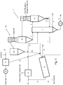
- Fig. 1
- is a simplified block diagram of a plant implementing the process of the present invention.
- In the plant shown in
Fig. 1 , a phosphorous-containing raw or starting material such as sewage sludge or biomass ash or rock phosphate is pneumatically conveyed from non-illustrated storage silos to afirst preheating stage 2 comprising a Venturisection 2a and acyclone separator 2b. Thereby, the starting material is intensively mixed with a hot combustion gas withdrawn from afirst reactor 1 and heated to a temperature of 400 to 600°C, preferably about 575°C. In thecyclone separator 2b the solid material is separated from the gas and transferred vialine 3 into thefirst reactor 1, which preferably is a fluidized bed reactor. In thefirst reactor 1, the preheated starting material is heated by the combustion of fuel, such as natural gas, biomass or sewage sludge supplied throughfuel line 4 with air supplied throughair line 5. The air may be introduced under elevated pressure viacompressor 6. In thefirst reactor 1 the starting material is heated to a temperature of 700 to 1.100°C, preferably 900 to 1.000°C and in particular about 950°C. - The thus heated starting material is withdrawn from the
first reactor 1 throughline 7 and is fed to asecond reactor 20, preferably a rotary kiln reactor. The level of the inventory in thefirst reactor 1 can be controlled by aseal pot 8 such as described in documentWO 2008/104250 A , a dip leg seal or the like. The combustion gases are withdrawn from thefirst reactor 1 throughline 9 into acyclone separator 10 for separating the gas from the solid material. The solid material is withdrawn at the bottom of thecyclone separator 10 and transferred to thesecond reactor 20 throughline 7. The hot combustion gases enter into the Venturisection 2a of thefirst preheating stage 2 for preheating the starting material. - From the
cyclone separator 2b of thefirst preheating stage 2 the gas is withdrawn at the top and enters a Venturisection 11a of asecond preheating stage 11 where soda ash is added as a preferred alkaline source and mixed with the heating gas. The mixture then is transferred into acyclone separator 11b for separating the solids from the gas. In thesecond preheating stage 11 the alkaline source is preheated to 300 to 400°C, preferably about 360°C, and then transferred into thesecond reactor 20 throughline 16. The gas is withdrawn at the top ofcyclone separator 11b and transferred intoseparator 13 vialine 12, where the solids are separated from the gas after a suitable, calcium or sodium based, sorbent such as calcium hydrate, calcium carbonate or sodium hydrogen carbonate has been added. Finally, after passing through afilter 14, preferably an electrostatic precipitator and other suitable cleaning device, for recovering additional solids that may be introduced into thesecond reactor 20 thoughline 15, the clean gas is removed from the plant. - The starting material supplied from the
first reactor 1 throughline 7 and the alkaline source supplied throughlines second reactor 20 and heated therein to a temperature of 700 to 1.100, preferably 900 to 1.000°C and in particular about 950°C. In addition to the starting material and the alkaline source an elemental carbon source, in particular pre-dried sewage sludge, biomass, pulverized lignite or coal and/or coke, is fed to thesecond reactor 20 throughline 17. Air may be introduced throughline 5. The compounds may be mixed before entering thesecond reactor 20 or supplied separately and mixed withinreactor 20, preferably by rotation. Thereby the alkaline source decomposes into X + Y (where X is the alkaline ion and Y is a carbonate or hydrogen anion) and the elemental carbon source reduces the heavy metals to their elemental form. For soda ash the reaction is as follows:
Na2CO3 + C → Na2O + 2CO
- The heavy metals evaporate and leave the
second reactor 20 with the process gas throughline 21. The remaining, phosphorus rich solids leave thesecond reactor 20 through a gas-tight outlet andproduct line 22 and are cooled. - The semi-product withdrawn through
product line 22 is free from toxic heavy metals and conveyed to a finishing section (not shown) where it is manufactured to straight phosphorus or complex fertilizers. - The process gas from the
second reactor 20 contains the elemental heavy metals. Said process gas is transmitted vialine 21 intoseparator 23 where it is quenched to about 200-400°C with fresh air or water to condensate the heavy metal compounds to solid particles. These particles are captured in a baghouse filter(not shown) as filter dust. Alternatively, the solids may be separated from the gas by electrostatic precipitation. Until heavy metal recycling will be commercially viable, the filter dust will be deposited as secondary waste. Finally, the purified process gas is fed back intofirst reactor 1 vialine 24. - At the point of leaving the thermo-chemical process, the semi-product already complies with the requirements of the fertilizer act. The concentration of toxic substances and particularly of cadmium and uranium is one to two orders of magnitude below the respective concentrations in phosphate rock based fertilizers.
- To comply with the phosphate concentration tolerances required by most fertilizer acts in the order of +/- 0.8 percentage points of total P2O5, a measured amount of a high grade straight phosphorus (P) carrier may be added to the semi-product. For this purpose, the semi-product is analyzed online for its concentration of P2O5 and one or several guiding heavy metals. Depending on the desired phosphate concentration in the final product, a measured quantity of triple-superphosphate (TSP) or phosphoric acid is admixed and homogenized. Alternatively and for the production of a phosphate fertilizer for organic farming, phosphate rock is used instead of TSP to adjust the P-concentration.
- As a first option the product is homogenized and granulated in a mixer-granulator and - depending on the final purpose - finished as dust free powder or as final granules. From this stage, the product has become the final product of the plant that either will be sold to the agricultural product distributors or to fertilizer manufacturers.
- As a second option, the plant can be extended to manufacture complex fertilizers by admixture of additional nutrient carriers. This step requires additional silos/storing facilities and the corresponding design of the finishing section of the plant to handle the additional nutrient and fertilizer quantities. In this case, the product and additional nutrient carriers are conveyed and fed to the mixer-granulator in ratios determined by the target fertilizer type. By adding small amounts of water and - depending on the requirements - binders and coating agents, complex fertilizer granules of homogenous composition and a determined corn size distribution are produced that comply with all requirements in terms of threshold values, tolerances and nutrient solubility.
- The raw material, ash, does not contain combustible and halogenic-organic substances. It mainly consists of phosphate, calcium, silicon, iron and aluminum compounds.
- The starting material treatment capacity of the plant may be e.g. 4-10 tons per hour. Raw materials are heated by natural gas burners or by combusting sewage sludge or biomass, and energy is efficiently recycled within the plant. Process emissions are effectively controlled by a sequence of adsorption reactors and baghouse filters. The heavy metals are captured as dry filter dust and safely disposed of in a landfill.
- Application of the product as a phosphate fertilizer is more environment friendly than using either conventional mineral fertilizers or recycled organic fertilizers. In comparison to conventional mineral fertilizers, concentrations of cadmium and uranium are 1-2 orders of magnitude lower. In comparison to organic fertilizers, no risk of transfer of organic pollutants to the food and feed chain exists.
- Additional nutrient carriers are exclusively licensed fertilizers as ammonium sulfate, potassium chloride (MOP), potassium sulfate (SOP) and converter slag. Triple-superphosphate and the finished products will be stored in silos or as bulk material in covered warehouses. Binders and coating agents and - on demand - phosphorus and sulfuric acid are stored in compliance with legal requirements.
-
- 1
- first reactor
- 2
- first preheating stage
- 2a
- Venturi section
- 2b
- cyclone separator
- 3
- line
- 4
- fuel line
- 5
- air line
- 6
- compressor
- 7
- line
- 8
- dip leg seal
- 9
- line
- 10
- cyclone separator
- 11
- first preheating stage
- 11a
- Venturi section
- 11b
- cyclone separator
- 12
- line
- 13
- separator
- 14
- filter
- 15
- line
- 16
- line
- 17
- line
- 20
- second reactor
- 21
- line
- 22
- product line
- 23
- separator
- 24
- line
Claims (15)
- A process for separating heavy metals from phosphoric starting material comprising the following steps:(i) heating the starting material to a temperature of 600 to 1.200°C in a first reactor (1) and withdrawing combustion gas;(ii) using the combustion gas of step (i) to preheat an alkaline source; and(iii) transferring the heated starting material of step (i) and the heated alkaline source of step (ii) to a second reactor (20), adding an elemental carbon source, heating to a temperature of 700 to 1.100°C and withdrawing process gas and a product stream.
- The process according to claim 1, characterized in that the starting material is pre-heated in at least a first preheating stage (2) to a temperature of 300 to 800°C prior to step (i).
- The process according to claim 1 or 2, characterized in that the starting material is pre-heated in multiple stages prior to step (i).
- The process according to any of the preceding claims, characterized in that the alkaline source is pre-heated in a second preheating stage (11) to a temperature of 200 to 500°C prior to the introduction into the second reactor (20).
- The process according to any of the preceding claims, characterized in that the alkaline source is selected from the group consisting of sodium carbonates, sodium hydroxides, potassium carbonates and potassium hydroxides or any combination thereof, wherein the alkaline source preferably is soda ash.
- The process according to any of the preceding claims, characterized in that the alkaline source is added in an amount of 2 to 80 wt.-%, preferably 10-50 wt.-%, of the starting material
- The process according to any of the preceding claims, characterized in that the elemental carbon source is selected from the group consisting of pulverized lignites, dry sewage sludge, dry biomass, pulverized lignite, coal and/or coke or any combination thereof, and wherein the elemental carbon source preferably is added in an amount of 1 to 40 wt.-%, more preferably 3 to 15 wt.- %, of the starting material.
- The process according to claim 2, characterized in that the combustion gases from step (i) are fed into a cyclone separator (10) and subsequently into a Venturi section (2a) of the first preheating stage (2).
- The process according to any of the preceding claims, characterized in that the combustion gases from step (i) are withdrawn from a cyclone separator (2b), enter a Venturi section (11a) and are admixed with an alkaline source according to step (ii).
- The process according to any of the preceding claims, characterized in that the process gas in step (iii) is cooled below the condensation temperature of the heavy metal compounds to allow for their precipitation and removal.
- The process according to claim 10, characterized in that the heavy metal-free process gas is recycled into the first reactor (1).
- A plant for separating heavy metals from phosphoric starting material adapted to perform a process as defined in any of the preceding claims, wherein the plant comprises a first reactor (1) adapted to heat the starting material to a temperature of 600 to 1.200°C, a first preheating stage (2) for preheating the starting material, a second preheating stage (11) for heating an alkaline source, and a second reactor (20) adapted to heat the heated starting material and the pre-heated alkaline source as well as an elemental carbon source to a temperature of 700 to 1.100°C and having at least one line (21) for withdrawing process gas and at least one product line (22) for withdrawing a product stream, and the first reactor (1) having at least one line for withdrawing combustion gas for preheating the alkaline source.
- The plant according to claim 12, characterized in that the first preheating stage (2) for preheating the starting material fed to the first reactor (1) comprises multiple stages.
- The plant according to claim 12 or 13, characterized in that the first and/or the second pre-heating stage (2; 11) each comprises a Venturi section (2a; 11a) and a cyclone separator (2b; 11b).
- The plant according to any of claims 12 to 14, characterized in that the first reactor (1) is a fluidized bed reactor and/or the second reactor (20) is a rotary kiln.
Applications Claiming Priority (1)
| Application Number | Priority Date | Filing Date | Title |
|---|---|---|---|
| PCT/EP2013/059285 WO2014177228A1 (en) | 2013-05-03 | 2013-05-03 | Process and plant for separating heavy metals from phosphoric starting material |
Publications (2)
| Publication Number | Publication Date |
|---|---|
| EP2992268A1 EP2992268A1 (en) | 2016-03-09 |
| EP2992268B1 true EP2992268B1 (en) | 2020-01-15 |
Family
ID=48430715
Family Applications (1)
| Application Number | Title | Priority Date | Filing Date |
|---|---|---|---|
| EP13722355.8A Active EP2992268B1 (en) | 2013-05-03 | 2013-05-03 | Process and plant for separating heavy metals from phosphorus-containing starting material |
Country Status (10)
| Country | Link |
|---|---|
| US (1) | US10081545B2 (en) |
| EP (1) | EP2992268B1 (en) |
| JP (1) | JP6174787B2 (en) |
| KR (1) | KR101782709B1 (en) |
| CN (1) | CN105324609B (en) |
| CA (1) | CA2910015A1 (en) |
| IL (1) | IL242276B (en) |
| MA (1) | MA38622B1 (en) |
| TN (1) | TN2015000478A1 (en) |
| WO (1) | WO2014177228A1 (en) |
Families Citing this family (2)
| Publication number | Priority date | Publication date | Assignee | Title |
|---|---|---|---|---|
| DE102016103349A1 (en) * | 2016-02-25 | 2017-08-31 | Outotec (Finland) Oy | Method and device for thermal treatment of a contaminated solid |
| JP7137223B2 (en) * | 2017-06-07 | 2022-09-14 | 国立大学法人 新潟大学 | Heavy metal separation method |
Family Cites Families (22)
| Publication number | Priority date | Publication date | Assignee | Title |
|---|---|---|---|---|
| DE2729277A1 (en) * | 1977-06-29 | 1979-01-04 | Saarberg Fernwaerme Gmbh | METHODS FOR TREATMENT OF SLUDGE OR ASH, IN PARTICULAR OF SEWING SLUDGE OR SEWING SLUDGE ASH |
| US4450146A (en) * | 1982-09-30 | 1984-05-22 | Stauffer Chemical Company | Heat recovery in P2 O5 production process |
| US4618483A (en) * | 1985-07-26 | 1986-10-21 | Stauffer Chemical Company | Heat recovery through oxidation of elemental phosphorus in a fluidized bed |
| EP0908673B1 (en) * | 1997-10-13 | 2002-05-15 | Alstom | Method for processing residues and/or ash from thermal treatment of refuse |
| US6022514A (en) * | 1998-05-18 | 2000-02-08 | Nkk Corporation | Method for recovering phosphorus from organic sludge |
| JP3917775B2 (en) * | 1999-03-30 | 2007-05-23 | 三菱重工業株式会社 | Recycling method of incineration ash |
| GB2359125A (en) * | 2000-02-08 | 2001-08-15 | Green Island Environmental Tec | Integrated cement production and waste disposal facility |
| KR20020009165A (en) | 2000-07-25 | 2002-02-01 | 김형벽ㅂ | Apparatus for treatment of wastewater containing heavy metals |
| JP2003112988A (en) * | 2001-10-01 | 2003-04-18 | Japan Sewage Works Agency | Method for manufacturing phosphorus fertilizer |
| DE10243840B4 (en) * | 2002-09-13 | 2004-07-22 | BAM Bundesanstalt für Materialforschung und -prüfung | Process for the separation of environmentally relevant heavy metals from sewage sludge ash |
| JP4040035B2 (en) | 2004-06-17 | 2008-01-30 | 住友重機械工業株式会社 | Sewage sludge treatment method and apparatus |
| EP1849755A4 (en) * | 2005-01-06 | 2011-05-11 | Sanki Eng Co Ltd | Process for producing phosphatic fertilizer and apparatus therefor |
| AT503073B1 (en) * | 2006-05-03 | 2009-08-15 | Ash Dec Umwelt Ag | METHOD FOR SEPARATING HEAVY METALS AND ASCHEAGGLOMERATE |
| CN101210281A (en) * | 2006-12-29 | 2008-07-02 | 铜陵有色设计研究院 | Comprehensive utilization method and device for copper-containing sulfuric acid cool baking slag |
| DE102007009758A1 (en) | 2007-02-27 | 2008-08-28 | Outotec Oyj | Solid container i.e. explosion-proof container, level and/or solid stock, regulating method, involves using level of solid flow or solid stock in solid container as controlled variable, and volume flow of gas as correcting variable of loop |
| JP5382679B2 (en) | 2008-03-31 | 2014-01-08 | 国立大学法人広島大学 | Phosphate recovery method |
| JP5478921B2 (en) | 2009-03-26 | 2014-04-23 | バブコック日立株式会社 | Smoke exhaust treatment apparatus and method |
| KR20120129879A (en) | 2009-12-09 | 2012-11-28 | 클로제, 잉게보르그 | Method for producing phosphates and compounds containing phosphate, in particular alkaline-earth phosphates, alkaline-earth silicophosphates or alkaline-earth oxides |
| AT509221B1 (en) * | 2009-12-28 | 2011-07-15 | Holcim Technology Ltd | METHOD FOR ASSESSING PHOSPHORUS-BASED ALTERNATIVE FUELS IN CEMENT MANUFACTURE |
| CN102277284A (en) * | 2010-06-09 | 2011-12-14 | 江苏丰山三栋保健食品有限责任公司 | Health-care snake wine and preparation method thereof |
| AT509593B1 (en) * | 2010-11-15 | 2011-10-15 | Sgl Carbon Se | METHOD FOR REPROCESSING ORGANIC WASTE MATERIALS |
| EA027805B1 (en) | 2012-06-21 | 2017-09-29 | Оутотек (Финлэнд) Ой | Process and plant for separating heavy metals from phosphoric starting material |
-
2013
- 2013-05-03 US US14/888,315 patent/US10081545B2/en active Active
- 2013-05-03 CN CN201380076311.XA patent/CN105324609B/en not_active Expired - Fee Related
- 2013-05-03 CA CA2910015A patent/CA2910015A1/en not_active Abandoned
- 2013-05-03 TN TN2015000478A patent/TN2015000478A1/en unknown
- 2013-05-03 JP JP2016510952A patent/JP6174787B2/en active Active
- 2013-05-03 MA MA38622A patent/MA38622B1/en unknown
- 2013-05-03 WO PCT/EP2013/059285 patent/WO2014177228A1/en active Application Filing
- 2013-05-03 EP EP13722355.8A patent/EP2992268B1/en active Active
- 2013-05-03 KR KR1020157034194A patent/KR101782709B1/en active IP Right Grant
-
2015
- 2015-10-26 IL IL242276A patent/IL242276B/en active IP Right Grant
Non-Patent Citations (1)
| Title |
|---|
| None * |
Also Published As
| Publication number | Publication date |
|---|---|
| KR101782709B1 (en) | 2017-09-27 |
| MA38622A1 (en) | 2016-08-31 |
| EP2992268A1 (en) | 2016-03-09 |
| MA38622B1 (en) | 2017-06-30 |
| KR20160003835A (en) | 2016-01-11 |
| CN105324609A (en) | 2016-02-10 |
| JP6174787B2 (en) | 2017-08-02 |
| US20160075555A1 (en) | 2016-03-17 |
| TN2015000478A1 (en) | 2017-04-06 |
| CA2910015A1 (en) | 2014-11-06 |
| IL242276B (en) | 2019-12-31 |
| CN105324609B (en) | 2018-03-30 |
| US10081545B2 (en) | 2018-09-25 |
| WO2014177228A1 (en) | 2014-11-06 |
| JP2016523790A (en) | 2016-08-12 |
Similar Documents
| Publication | Publication Date | Title |
|---|---|---|
| Masto et al. | PAHs and potentially toxic elements in the fly ash and bed ash of biomass fired power plants | |
| EP3681845B1 (en) | Nutrient and energy recovery from sewage sludge and animal manure | |
| US4503018A (en) | Desulfurization of phosphogypsum | |
| Gorazda et al. | Phosphorus cycle-possibilities for its rebuilding | |
| US10259752B2 (en) | Production of citrate soluble phosphates by calcination of secondary phosphate sources with a sodium-sulfuric compound | |
| US11167989B2 (en) | Method for recovering phosphorus | |
| US9840415B2 (en) | Process and plant for separating heavy metals from phosphoric starting material | |
| EP2992268B1 (en) | Process and plant for separating heavy metals from phosphorus-containing starting material | |
| Canziani et al. | Phosphorus recovery—recent developments and case studies | |
| WO2014158058A1 (en) | Method for producing phosphorus-containing fertiliser from silt deposits of municipal wastewater treatment plants and a fertiliser produced by this method | |
| US6051201A (en) | Preparation of phosphatic feedstock from phosphorus-containing waste | |
| EP2864511A1 (en) | Process and plant for separating heavy metals from phosphoric starting material | |
| Boniardi | Phosphorous recovery from sewage sludge ashes via wet chemical leaching |
Legal Events
| Date | Code | Title | Description |
|---|---|---|---|
| PUAI | Public reference made under article 153(3) epc to a published international application that has entered the european phase |
Free format text: ORIGINAL CODE: 0009012 |
|
| 17P | Request for examination filed |
Effective date: 20151022 |
|
| AK | Designated contracting states |
Kind code of ref document: A1 Designated state(s): AL AT BE BG CH CY CZ DE DK EE ES FI FR GB GR HR HU IE IS IT LI LT LU LV MC MK MT NL NO PL PT RO RS SE SI SK SM TR |
|
| AX | Request for extension of the european patent |
Extension state: BA ME |
|
| DAX | Request for extension of the european patent (deleted) | ||
| STAA | Information on the status of an ep patent application or granted ep patent |
Free format text: STATUS: EXAMINATION IS IN PROGRESS |
|
| 17Q | First examination report despatched |
Effective date: 20161115 |
|
| GRAP | Despatch of communication of intention to grant a patent |
Free format text: ORIGINAL CODE: EPIDOSNIGR1 |
|
| STAA | Information on the status of an ep patent application or granted ep patent |
Free format text: STATUS: GRANT OF PATENT IS INTENDED |
|
| INTG | Intention to grant announced |
Effective date: 20190902 |
|
| GRAS | Grant fee paid |
Free format text: ORIGINAL CODE: EPIDOSNIGR3 |
|
| GRAA | (expected) grant |
Free format text: ORIGINAL CODE: 0009210 |
|
| STAA | Information on the status of an ep patent application or granted ep patent |
Free format text: STATUS: THE PATENT HAS BEEN GRANTED |
|
| AK | Designated contracting states |
Kind code of ref document: B1 Designated state(s): AL AT BE BG CH CY CZ DE DK EE ES FI FR GB GR HR HU IE IS IT LI LT LU LV MC MK MT NL NO PL PT RO RS SE SI SK SM TR |
|
| REG | Reference to a national code |
Ref country code: CH Ref legal event code: EP Ref country code: GB Ref legal event code: FG4D |
|
| REG | Reference to a national code |
Ref country code: IE Ref legal event code: FG4D |
|
| REG | Reference to a national code |
Ref country code: DE Ref legal event code: R096 Ref document number: 602013065097 Country of ref document: DE |
|
| REG | Reference to a national code |
Ref country code: AT Ref legal event code: REF Ref document number: 1225472 Country of ref document: AT Kind code of ref document: T Effective date: 20200215 |
|
| REG | Reference to a national code |
Ref country code: NL Ref legal event code: FP |
|
| REG | Reference to a national code |
Ref country code: SE Ref legal event code: TRGR |
|
| REG | Reference to a national code |
Ref country code: NO Ref legal event code: T2 Effective date: 20200115 |
|
| REG | Reference to a national code |
Ref country code: LT Ref legal event code: MG4D |
|
| PG25 | Lapsed in a contracting state [announced via postgrant information from national office to epo] |
Ref country code: FI Free format text: LAPSE BECAUSE OF FAILURE TO SUBMIT A TRANSLATION OF THE DESCRIPTION OR TO PAY THE FEE WITHIN THE PRESCRIBED TIME-LIMIT Effective date: 20200115 Ref country code: PT Free format text: LAPSE BECAUSE OF FAILURE TO SUBMIT A TRANSLATION OF THE DESCRIPTION OR TO PAY THE FEE WITHIN THE PRESCRIBED TIME-LIMIT Effective date: 20200607 Ref country code: RS Free format text: LAPSE BECAUSE OF FAILURE TO SUBMIT A TRANSLATION OF THE DESCRIPTION OR TO PAY THE FEE WITHIN THE PRESCRIBED TIME-LIMIT Effective date: 20200115 |
|
| PG25 | Lapsed in a contracting state [announced via postgrant information from national office to epo] |
Ref country code: HR Free format text: LAPSE BECAUSE OF FAILURE TO SUBMIT A TRANSLATION OF THE DESCRIPTION OR TO PAY THE FEE WITHIN THE PRESCRIBED TIME-LIMIT Effective date: 20200115 Ref country code: GR Free format text: LAPSE BECAUSE OF FAILURE TO SUBMIT A TRANSLATION OF THE DESCRIPTION OR TO PAY THE FEE WITHIN THE PRESCRIBED TIME-LIMIT Effective date: 20200416 Ref country code: LV Free format text: LAPSE BECAUSE OF FAILURE TO SUBMIT A TRANSLATION OF THE DESCRIPTION OR TO PAY THE FEE WITHIN THE PRESCRIBED TIME-LIMIT Effective date: 20200115 Ref country code: IS Free format text: LAPSE BECAUSE OF FAILURE TO SUBMIT A TRANSLATION OF THE DESCRIPTION OR TO PAY THE FEE WITHIN THE PRESCRIBED TIME-LIMIT Effective date: 20200515 Ref country code: BG Free format text: LAPSE BECAUSE OF FAILURE TO SUBMIT A TRANSLATION OF THE DESCRIPTION OR TO PAY THE FEE WITHIN THE PRESCRIBED TIME-LIMIT Effective date: 20200415 |
|
| REG | Reference to a national code |
Ref country code: DE Ref legal event code: R097 Ref document number: 602013065097 Country of ref document: DE |
|
| PG25 | Lapsed in a contracting state [announced via postgrant information from national office to epo] |
Ref country code: ES Free format text: LAPSE BECAUSE OF FAILURE TO SUBMIT A TRANSLATION OF THE DESCRIPTION OR TO PAY THE FEE WITHIN THE PRESCRIBED TIME-LIMIT Effective date: 20200115 Ref country code: RO Free format text: LAPSE BECAUSE OF FAILURE TO SUBMIT A TRANSLATION OF THE DESCRIPTION OR TO PAY THE FEE WITHIN THE PRESCRIBED TIME-LIMIT Effective date: 20200115 Ref country code: CZ Free format text: LAPSE BECAUSE OF FAILURE TO SUBMIT A TRANSLATION OF THE DESCRIPTION OR TO PAY THE FEE WITHIN THE PRESCRIBED TIME-LIMIT Effective date: 20200115 Ref country code: LT Free format text: LAPSE BECAUSE OF FAILURE TO SUBMIT A TRANSLATION OF THE DESCRIPTION OR TO PAY THE FEE WITHIN THE PRESCRIBED TIME-LIMIT Effective date: 20200115 Ref country code: SM Free format text: LAPSE BECAUSE OF FAILURE TO SUBMIT A TRANSLATION OF THE DESCRIPTION OR TO PAY THE FEE WITHIN THE PRESCRIBED TIME-LIMIT Effective date: 20200115 Ref country code: EE Free format text: LAPSE BECAUSE OF FAILURE TO SUBMIT A TRANSLATION OF THE DESCRIPTION OR TO PAY THE FEE WITHIN THE PRESCRIBED TIME-LIMIT Effective date: 20200115 Ref country code: DK Free format text: LAPSE BECAUSE OF FAILURE TO SUBMIT A TRANSLATION OF THE DESCRIPTION OR TO PAY THE FEE WITHIN THE PRESCRIBED TIME-LIMIT Effective date: 20200115 Ref country code: SK Free format text: LAPSE BECAUSE OF FAILURE TO SUBMIT A TRANSLATION OF THE DESCRIPTION OR TO PAY THE FEE WITHIN THE PRESCRIBED TIME-LIMIT Effective date: 20200115 |
|
| REG | Reference to a national code |
Ref country code: AT Ref legal event code: MK05 Ref document number: 1225472 Country of ref document: AT Kind code of ref document: T Effective date: 20200115 |
|
| PLBE | No opposition filed within time limit |
Free format text: ORIGINAL CODE: 0009261 |
|
| STAA | Information on the status of an ep patent application or granted ep patent |
Free format text: STATUS: NO OPPOSITION FILED WITHIN TIME LIMIT |
|
| 26N | No opposition filed |
Effective date: 20201016 |
|
| PG25 | Lapsed in a contracting state [announced via postgrant information from national office to epo] |
Ref country code: AT Free format text: LAPSE BECAUSE OF FAILURE TO SUBMIT A TRANSLATION OF THE DESCRIPTION OR TO PAY THE FEE WITHIN THE PRESCRIBED TIME-LIMIT Effective date: 20200115 Ref country code: IT Free format text: LAPSE BECAUSE OF FAILURE TO SUBMIT A TRANSLATION OF THE DESCRIPTION OR TO PAY THE FEE WITHIN THE PRESCRIBED TIME-LIMIT Effective date: 20200115 Ref country code: MC Free format text: LAPSE BECAUSE OF FAILURE TO SUBMIT A TRANSLATION OF THE DESCRIPTION OR TO PAY THE FEE WITHIN THE PRESCRIBED TIME-LIMIT Effective date: 20200115 |
|
| PG25 | Lapsed in a contracting state [announced via postgrant information from national office to epo] |
Ref country code: PL Free format text: LAPSE BECAUSE OF FAILURE TO SUBMIT A TRANSLATION OF THE DESCRIPTION OR TO PAY THE FEE WITHIN THE PRESCRIBED TIME-LIMIT Effective date: 20200115 Ref country code: SI Free format text: LAPSE BECAUSE OF FAILURE TO SUBMIT A TRANSLATION OF THE DESCRIPTION OR TO PAY THE FEE WITHIN THE PRESCRIBED TIME-LIMIT Effective date: 20200115 |
|
| REG | Reference to a national code |
Ref country code: BE Ref legal event code: MM Effective date: 20200531 |
|
| GBPC | Gb: european patent ceased through non-payment of renewal fee |
Effective date: 20200503 |
|
| PG25 | Lapsed in a contracting state [announced via postgrant information from national office to epo] |
Ref country code: LU Free format text: LAPSE BECAUSE OF NON-PAYMENT OF DUE FEES Effective date: 20200503 |
|
| PG25 | Lapsed in a contracting state [announced via postgrant information from national office to epo] |
Ref country code: GB Free format text: LAPSE BECAUSE OF NON-PAYMENT OF DUE FEES Effective date: 20200503 Ref country code: FR Free format text: LAPSE BECAUSE OF NON-PAYMENT OF DUE FEES Effective date: 20200531 Ref country code: IE Free format text: LAPSE BECAUSE OF NON-PAYMENT OF DUE FEES Effective date: 20200503 |
|
| PG25 | Lapsed in a contracting state [announced via postgrant information from national office to epo] |
Ref country code: BE Free format text: LAPSE BECAUSE OF NON-PAYMENT OF DUE FEES Effective date: 20200531 |
|
| PG25 | Lapsed in a contracting state [announced via postgrant information from national office to epo] |
Ref country code: HR Free format text: LAPSE BECAUSE OF FAILURE TO SUBMIT A TRANSLATION OF THE DESCRIPTION OR TO PAY THE FEE WITHIN THE PRESCRIBED TIME-LIMIT Effective date: 20210323 |
|
| PG25 | Lapsed in a contracting state [announced via postgrant information from national office to epo] |
Ref country code: TR Free format text: LAPSE BECAUSE OF FAILURE TO SUBMIT A TRANSLATION OF THE DESCRIPTION OR TO PAY THE FEE WITHIN THE PRESCRIBED TIME-LIMIT Effective date: 20200115 Ref country code: MT Free format text: LAPSE BECAUSE OF FAILURE TO SUBMIT A TRANSLATION OF THE DESCRIPTION OR TO PAY THE FEE WITHIN THE PRESCRIBED TIME-LIMIT Effective date: 20200115 Ref country code: CY Free format text: LAPSE BECAUSE OF FAILURE TO SUBMIT A TRANSLATION OF THE DESCRIPTION OR TO PAY THE FEE WITHIN THE PRESCRIBED TIME-LIMIT Effective date: 20200115 |
|
| PG25 | Lapsed in a contracting state [announced via postgrant information from national office to epo] |
Ref country code: MK Free format text: LAPSE BECAUSE OF FAILURE TO SUBMIT A TRANSLATION OF THE DESCRIPTION OR TO PAY THE FEE WITHIN THE PRESCRIBED TIME-LIMIT Effective date: 20200115 Ref country code: AL Free format text: LAPSE BECAUSE OF FAILURE TO SUBMIT A TRANSLATION OF THE DESCRIPTION OR TO PAY THE FEE WITHIN THE PRESCRIBED TIME-LIMIT Effective date: 20200115 |
|
| REG | Reference to a national code |
Ref country code: NL Ref legal event code: PD Owner name: METSO MINERALS OY; FI Free format text: DETAILS ASSIGNMENT: CHANGE OF OWNER(S), MERGE; FORMER OWNER NAME: OUTOTEC (FINLAND) OY Effective date: 20230118 Ref country code: NL Ref legal event code: HC Owner name: METSO OUTOTEC FINLAND OY; FI Free format text: DETAILS ASSIGNMENT: CHANGE OF OWNER(S), CHANGE OF OWNER(S) NAME; FORMER OWNER NAME: METSO MINERALS OY Effective date: 20230118 |
|
| REG | Reference to a national code |
Ref country code: DE Ref legal event code: R081 Ref document number: 602013065097 Country of ref document: DE Owner name: METSO OUTOTEC FINLAND OY, FI Free format text: FORMER OWNER: OUTOTEC (FINLAND) OY, ESPOO, FI Ref country code: DE Ref legal event code: R081 Ref document number: 602013065097 Country of ref document: DE Owner name: METSO METALS OY, FI Free format text: FORMER OWNER: OUTOTEC (FINLAND) OY, ESPOO, FI |
|
| REG | Reference to a national code |
Ref country code: NO Ref legal event code: CHAD Owner name: METSO OUTOTEC FINLAND OY, FI |
|
| REG | Reference to a national code |
Ref country code: NL Ref legal event code: PD Owner name: METSO OUTOTEC METALS OY; FI Free format text: DETAILS ASSIGNMENT: CHANGE OF OWNER(S), ASSIGNMENT; FORMER OWNER NAME: OUTOTEC (FINLAND) OY Effective date: 20240403 Ref country code: NL Ref legal event code: HC Owner name: METSO METALS OY; FI Free format text: DETAILS ASSIGNMENT: CHANGE OF OWNER(S), CHANGE OF OWNER(S) NAME; FORMER OWNER NAME: METSO OUTOTEC METALS OY Effective date: 20240403 |
|
| PGFP | Annual fee paid to national office [announced via postgrant information from national office to epo] |
Ref country code: NL Payment date: 20240521 Year of fee payment: 12 |
|
| PGFP | Annual fee paid to national office [announced via postgrant information from national office to epo] |
Ref country code: DE Payment date: 20240521 Year of fee payment: 12 |
|
| PGFP | Annual fee paid to national office [announced via postgrant information from national office to epo] |
Ref country code: CH Payment date: 20240602 Year of fee payment: 12 |
|
| PGFP | Annual fee paid to national office [announced via postgrant information from national office to epo] |
Ref country code: NO Payment date: 20240528 Year of fee payment: 12 |
|
| REG | Reference to a national code |
Ref country code: DE Ref legal event code: R081 Ref document number: 602013065097 Country of ref document: DE Owner name: METSO METALS OY, FI Free format text: FORMER OWNER: METSO OUTOTEC FINLAND OY, HELSINKI, FI |
|
| PGFP | Annual fee paid to national office [announced via postgrant information from national office to epo] |
Ref country code: SE Payment date: 20240521 Year of fee payment: 12 |