EP2992255B1 - Electrical actuated valve for volume flow control in a heating or cooling system of a vehicle - Google Patents
Electrical actuated valve for volume flow control in a heating or cooling system of a vehicle Download PDFInfo
- Publication number
- EP2992255B1 EP2992255B1 EP14723740.8A EP14723740A EP2992255B1 EP 2992255 B1 EP2992255 B1 EP 2992255B1 EP 14723740 A EP14723740 A EP 14723740A EP 2992255 B1 EP2992255 B1 EP 2992255B1
- Authority
- EP
- European Patent Office
- Prior art keywords
- valve
- valve body
- housing
- valve according
- control contour
- Prior art date
- Legal status (The legal status is an assumption and is not a legal conclusion. Google has not performed a legal analysis and makes no representation as to the accuracy of the status listed.)
- Not-in-force
Links
Images


Classifications
-
- F—MECHANICAL ENGINEERING; LIGHTING; HEATING; WEAPONS; BLASTING
- F16—ENGINEERING ELEMENTS AND UNITS; GENERAL MEASURES FOR PRODUCING AND MAINTAINING EFFECTIVE FUNCTIONING OF MACHINES OR INSTALLATIONS; THERMAL INSULATION IN GENERAL
- F16K—VALVES; TAPS; COCKS; ACTUATING-FLOATS; DEVICES FOR VENTING OR AERATING
- F16K31/00—Actuating devices; Operating means; Releasing devices
- F16K31/02—Actuating devices; Operating means; Releasing devices electric; magnetic
-
- F—MECHANICAL ENGINEERING; LIGHTING; HEATING; WEAPONS; BLASTING
- F16—ENGINEERING ELEMENTS AND UNITS; GENERAL MEASURES FOR PRODUCING AND MAINTAINING EFFECTIVE FUNCTIONING OF MACHINES OR INSTALLATIONS; THERMAL INSULATION IN GENERAL
- F16K—VALVES; TAPS; COCKS; ACTUATING-FLOATS; DEVICES FOR VENTING OR AERATING
- F16K11/00—Multiple-way valves, e.g. mixing valves; Pipe fittings incorporating such valves
- F16K11/02—Multiple-way valves, e.g. mixing valves; Pipe fittings incorporating such valves with all movable sealing faces moving as one unit
- F16K11/06—Multiple-way valves, e.g. mixing valves; Pipe fittings incorporating such valves with all movable sealing faces moving as one unit comprising only sliding valves, i.e. sliding closure elements
- F16K11/072—Multiple-way valves, e.g. mixing valves; Pipe fittings incorporating such valves with all movable sealing faces moving as one unit comprising only sliding valves, i.e. sliding closure elements with pivoted closure members
- F16K11/074—Multiple-way valves, e.g. mixing valves; Pipe fittings incorporating such valves with all movable sealing faces moving as one unit comprising only sliding valves, i.e. sliding closure elements with pivoted closure members with flat sealing faces
Definitions
- the invention relates to an electrically drivable valve for controlling volume flows in a heating and / or cooling system of a motor vehicle according to the preamble of claim 1.
- Cooling systems of the motor vehicle consist of an internal combustion engine, a heat sink, a pump and a control valve.
- valve with disk-shaped valve body is disclosed in DE 10 2006 053 310 A1.
- the valve has a housing with at least one inlet channel and at least one outlet channel, wherein the disc-shaped valve body is rotatably mounted about the axis of a shaft.
- the valve body has a Drehwinkefablfitige opening characteristic for controlling the volume flows, wherein a plurality of discrete openings for connection of a single inlet channel to the one outlet channel are provided. This results in adjusting the valve body that the edges of the plurality of openings constantly slide over seals and thus a strong wear on the seal is caused. The inflow and outflow of the coolant takes place axially to the axis of rotation in the opposite direction.
- a disadvantage of the electrically driven valves that extensive sealing material for sealing the plurality of openings is necessary, whereby the valve is structurally complex and very expensive. At the same time, a heavy wear of the seals shortens the life of the valve.
- valves for controlling volume flows in heating or cooling systems of motor vehicles are out WO03 / 036145 .
- DE4324749 WO2011 / 086154 or DE19932313 known.
- a control contour of the valve body controls a short circuit and a radiator circuit of the heating and / or cooling system and the valve body is provided on its surface with a seal for sealing against the housing, or for sealing of the valve body relative to the housing, a seal is arranged in the housing.
- the only one control contour forms only one passage for the coolant on the valve body.
- Such a valve can be used both as an inlet controller and as outlet regulator for the coolant of an internal combustion engine.
- control contour is formed as an opening of the fully circular valve body.
- the constructive effort in the production of the valve is reduced, which reduces costs.
- control contour is formed by an outer shape of a circular segment-like, full-surface formed valve body.
- a passage for the volume flow is created by the non-circular outer shape of the disc-shaped valve body, which allows depending on the position of the valve body a corresponding control.
- control contour is formed as a backdrop on a lateral surface of the valve body.
- a backdrop which expands approximately parallel to the housing, thereby advantageously has the function to regulate an additional coolant circuit.
- valve body is pivotally formed against the axis.
- the valve body In addition to the rotation of the valve body about the axis of the pivoting of the valve body relative to the axis of rotation provides an additional degree of freedom in the movement of the disc-like valve body. This allows the trained as an electric motor drive the valve body to work with less force.
- the rotatably mounted on the axis valve body is simply fluctuate depending on the specifications of a control unit its angle of rotation.
- the valve body consists of metal or of a coolant-resistant plastic, wherein the plastic preferably contains glass fibers and / or slip-optimizing additives.
- the additions account for between 10% and 70%.
- slip-optimizing additives allows easy movement of the valve body with reduced friction.
- valve body is provided on its surface with a seal for sealing against the housing.
- the seal is arranged in the housing for sealing the valve body.
- the seals may be formed in particular as a form seals and form a positive connection for sufficient sealing.
- valve body arranged on a shaft together with the shaft or only the valve body is biased by means of at least one resilient element to an opening of at least one connecting piece. Due to this bias, it is possible that the Valve body executes an adjusting movement with the wear of the seal so as not to exceed a prescribed over the life of the valve leakage.
- a Dehnstoffthermostat is arranged as a fail-safe valve of the valve in the housing.
- the expansion thermostat ensures sufficient cooling of the engine when a critical temperature of the coolant is reached, thereby preventing thermal damage to the heating and / or cooling system.
- the position of the expansion thermostat in the housing is the same when using the valve as an inlet or outlet regulator.
- the housing has connections for hoses of a separate expansion thermostat.
- the thermostat can also be arranged outside of the valve, whereby it is easier to replace if necessary.
- a housing wall of the actuator, by which the valve is electrically driven at the same time a wall of the housing of the valve.
- a positional reset of the valve body takes place via a Hall sensor or a Hall switch.
- the reference points of the Hall switch are formed via one or more mechanically formed end positions or via magnets.
- the Fig. 1 shows a cooling circuit 1 of a motor vehicle with the valve 2 according to the invention as an inlet controller.
- the cooling circuit 1 in this case has an internal combustion engine 3, the engine outlet 4 is connected to a heat sink 5.
- the radiator return 6 is connected to the valve 2.
- the output of the valve 2 leads to the suction side 22 of a pump 7, which in turn is connected to an internal combustion engine 3.
- a bypass or a short circuit line 9 is provided, which the engine outlet 4 directly to the Valve 2 and thus again with the pump 7 and the internal combustion engine 3 connects.
- the heat sink 5 is cooled with air (arrow P). Behind the heat sink 5 is a fan 10th
- Fig. 2 differs from Fig. 1 merely to the effect that the valve 2 operates as an outlet regulator and is thus connected between the engine outlet 4 and the radiator feed 8. At the same time, the valve 2 controls the short-circuit 9, which connects the motor outlet 4 with the suction side 22 of the pump 7.
- valve outlet is directed onto the suction side 22 of the pump 7, the short circuit 9 and the radiator return 6 form the valve inlets.
- the engine outlet 4 forms the valve inlet, while the short circuit 9 and the radiator inlet 8 form the two valve outputs.
- Fig. 3 is the operating as inlet control valve 2 shown.
- the valve 2 comprises a housing 11, which has three connecting pieces 12, 13, 14.
- the connecting piece 12 in this case connects the valve 2 to the pump 7 and thus represents an outlet channel.
- the second connecting piece 13 connects the valve 2 to the short circuit 9, while the third connecting piece 14 connects the valve 2 to the radiator return 6.
- the connecting pieces 13 and 14 thus represent input channels.
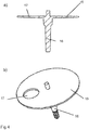
- the valve body 15 is, as in Fig. 4a and b shown formed as a fully circular, disc-shaped body, which has a decentralized opening 17 as a control contour.
- a control contour forms a single passage for the coolant within the inlet or outlet regulator 2, 3.
- Fig. 5 shows a control contour, which is designed as a gate 18 on the shell side 19 of the valve body 15.
- a control contour which is designed as a gate 18 on the shell side 19 of the valve body 15.
- an additional coolant circuit can be regulated.
- a heating circuit can be released in order, for example, to increase passenger comfort during winter operation.
- the gate 18 also allows an unregulated inflow / outflow of additional coolant circuits in the valve. 2
- Fig. 5b shows a circular segment similar valve body 20.
- this circular segment-like valve body 20 By means of this circular segment-like valve body 20, only the desired channel is closed, while the opening 17 of the embodiment of the valve body 15 after Fig. 5a the desired inlet or outlet nozzle 12, 13, 14 releases. In both cases, the flow passing through the valve 2 runs approximately parallel to the axis of rotation of the valve body 15, 20 and always in one direction.
- the valve body 15 or 20 is made of a metal or of a sprayable plastic. In the case of the execution of plastic, this preferably contains glass fibers in a proportion of between 10% and 70% and is resistant to the coolant.
- slip-optimizing additives such as PTFE (polytetrafluoroethylene) can be used in the plastic. These slip-optimizing additives reduce the friction of the Valve body 15, 20 on the housing 11.
- the valve body 15, 20 should have on an outer surface a flatness of less than +/- 0.5 mm.
- the disc-shaped valve body 15, 20 has one or more recesses or that it is coated on its outer surface and / or lateral surface 19 with a sealing material.
- the valve body 15, 20 may have on its surface elevations or the valve body 15, 20 non-penetrating recesses.
- the valve body 15, 20 and the shaft 16 may be a plastic component. Alternatively, however, the valve body 15, 20 can also be sprayed onto a shaft 16 made of, for example, steel. Alternatively, the shaft 16 may be formed at least partially continuous, on which the valve body 15, 20 is rotatably mounted and pivotable about the axis of the shaft 16. Alternatively, the disc-shaped valve body 15, 20 are axially slidably mounted on this shaft 16.
- an outer contour or an inner contour may be formed, which constitute a positive connection to an electric drive, not shown.
- the valve body 15 and 20 can be further characterized as a whole, ie together with the shaft 16 or only on the shaft 16 itself, when the valve body 15 and the shaft 16 are formed separately, by means of mechanical, preferably resilient elements under bias against one or more the openings of the connecting pieces 13, 14 are. By this bias an adjusting movement is carried out by the valve body 15 and 20 at closing seal and thus a prescribed leakage over the life of the valve 2 is not exceeded.
- the mechanical, in particular resilient element is designed so that with fully closed valve 2 (eg stationary coolant in warm-up) and simultaneously high speed of the pump 7 and thus high applied hydraulic differential pressure of the valve body 15 or 20 pushed away from the seal not shown and thus can flow coolant. This is especially helpful whenever the driver of the motor vehicle immediately sets a high speed during cold start, which can lead to critical temperatures or local temperature peaks in the internal combustion engine or cavitation on the suction side of the pump.
- the seal to the valve body 15, 20 can also be done by introduced into the housing 11 seals. These can be injected or mechanically inserted.
- the seals are elastomers, preferably EPDM (ethylene-propylene-diene rubber) or HNBR (hydrogenated acrylonitrile-butadiene rubber). These are advantageously coated with a friction-reducing material such as PTFE or parylene or they are contained in the outer layers of the elastomer.
- elastomers may also be used to form a friction-optimized sealing material, e.g. PTFE to press elastically against the valve body 15, 20.
- an expansion thermostat 21 is inserted into the valve 2, as it is in Fig. 6 is shown.
- the expansion thermostat works as a fail-safe mechanism.
- Such expansion thermostats 21 ensure that upon reaching a critical temperature with simultaneous failure of the normal operation of the valve sufficient cooling of the Internal combustion engine is adjusted.
- Such expansion thermostat 21 is directly dependent on its temperature and thus on the coolant temperature and the flow rate of the coolant around the thermostat around.
- the position of the expansion thermostat 21 in the housing 11 is independent of whether the valve is used as an inlet controller 2 or as outlet regulator 3.
- the expansion fluid thermostat 21 When inserted as an inlet regulator, the expansion fluid thermostat 21 connects the radiator return inlet to the pump 7 or the engine outlet 4 (FIG. Fig. 6a ). When used as an outlet regulator, the thermostat 21 connects the motor outlet 4 with the radiator run 8 of the valve 2 (FIG. Fig. 6b ).
- the drive of the valve body 15 or 20 takes place via an electric motor, which is arranged in an actuator unit together with a gear and a sensor for the feedback of the position of the valve body 15, 20.
- the electric motor is advantageously a DC motor.
- this actuator unit is attached to the valve 2 as an independent component. It is particularly advantageous if a housing outer wall of the actuator simultaneously forms an inner side of the housing 11 of the valve 2.
- the material expenditure for the valve housing can be reduced, on the other hand, however, the number of components of the valve 2 can also be reduced by e.g. Welienlager and shaft seal to the actuator not in the housing 11 of the valve 2 must be introduced, since these are usually already present in the actuator unit.
- a Hall switch a relative measurement of the position of the valve body 15, 20 to one or several end positions, but preferably by reference points represented by magnets, measures are used.
- the described valve 2 which due to its simple structure can be used both as an inlet regulator and as an outlet regulator in a cooling circuit, can be designed so that only the two switching states are realized open and closed. However, any intermediate state, in particular stepless, is also possible.
- the valve 2 is thus a control element that adjusts the temperature of the coolant by controlling the volume flow of the coolant depending on the desired operating temperature of one or more components, wherein the volume flow through one or more warmer circles (eg short circuit) and / or can flow over one or more colder circuits (eg radiator circuit).
- a temperature sensor can be arranged in the housing of the valve 2. Further, it is possible to arrange the valve together with a coolant pump in a common housing.
Description
Die Erfindung betrifft ein elektrisch antreibbares Ventil zur Regelung von Volumenströmen in einem Heiz- und/oder Kühlsystem eines Kraftfahrzeuges nach dem Oberbegriff von Anspruch 1.The invention relates to an electrically drivable valve for controlling volume flows in a heating and / or cooling system of a motor vehicle according to the preamble of
In Kühlsysteme von Kraftfahrzeugen wird heute ein Thermomanagement zur Verbrauchsreduktion, zur Verringerung der CO2-Emissionen und zur Komforterhöhung durchgeführt. Je nach thermischen Anforderungen wird dabei Kühlmittelstillstand im Warmlauf realisiert, die Kühlmitteltemperatur der Verbrennungskraftmaschine je nach Lastbedingungen geregelt sowie ein oder mehrere Nebenkreise wie Getriebeöl-, Motoröl- oder Heizkreis geregelt oder geschaltet. Kühlsysteme des Kraftfahrzeuges bestehen dabei aus einem Verbrennungsmotor, einem Kühlkörper, einer Pumpe und einem Regelventil.In motor vehicle cooling systems, thermal management is now being implemented to reduce fuel consumption, reduce CO 2 emissions and increase comfort. Depending on the thermal requirements while coolant standstill is realized during warm-up, controlled the coolant temperature of the internal combustion engine depending on the load conditions and regulated or switched one or more secondary circuits such as Getriebeöl-, engine oil or heating circuit. Cooling systems of the motor vehicle consist of an internal combustion engine, a heat sink, a pump and a control valve.
Aus der
Ebenfalls ein Ventil mit scheibenförmigem Ventilkörper ist in der DIE 10 2006 053 310 A1 offenbart. Das Ventil weist ein Gehäuse mit mindestens einem Einlasskanal und mindestens einem Auslasskanal auf, wobei der scheibenförmige Ventilkörper um die Achse einer Welle drehbar gelagert ist. Darüber hinaus weist der Ventilkörper eine drehwinkefablängige Öffnungscharakteristik zum Regeln der Volumenströme auf, wobei mehrere diskrete Öffnungen zur Verbindung eines einzelnen Einlasskanals mit dem einen Auslasskanal vorgesehen sind. Dies führt beim Verstellen des Ventilkörpers dazu, dass die Ränder der mehreren Öffnungen ständig über Dichtungen gleiten und somit ein starker Verschleiß an der Dichtung hervorgerufen wird. Die An- und Abströmung des Kühlmittels erfolgt axial zur Drehachse in entgegengesetzter Richtung.Likewise a valve with disk-shaped valve body is disclosed in
Nachteilig für die elektrisch angetriebenen Ventile ist, dass umfangreiches Dichtungsmaterial zur Abdichtung der Vielzahl der Öffnungen notwendig ist, wodurch das Ventil konstruktiv aufwändig und sehr kostenintensiv ist. Gleichzeitig verkürzt eine starke Abnutzung der Dichtungen die Lebensdauer des Ventils.A disadvantage of the electrically driven valves that extensive sealing material for sealing the plurality of openings is necessary, whereby the valve is structurally complex and very expensive. At the same time, a heavy wear of the seals shortens the life of the valve.
Andere Ventile zur Regelung von Volumenströmen in Heiz- oder Kühlsystemen der Kraftfahrzeuge, sind aus
Es ist die Aufgabe der Erfindung, ein elektrisch antreibbares Ventil zu schaffen, welches konstruktiv einfach gestaltet ist und eine lange Lebensdauer aufweist.It is the object of the invention to provide an electrically driven valve, which is structurally simple and has a long service life.
Dies wird erreicht mit den Merkmalen von Anspruch 1, wonach die nur eine Regelkontur des Ventilkörpers einen Kurzschlusskreislauf und einen Kühlerkreislauf des Heiz- und/oder Kühlsystems regelt und der Ventilkörper ist auf seiner Oberfläche mit einer Dichtung zur Abdichtung gegenüber dem Gehäuse versehen, oder zur Abdichtung des Ventilkörpers gegenüber dem Gehäuse ist eine Dichtung im Gehäuse angeordnet. Dies hat den Vorteil, dass durch Verwendung nur einer Regelkontur des Ventilkörpers sich der Dichtungsaufwand reduziert. Gleichzeitig wird der Dichtungsverschleiß gesenkt, wodurch sich die Lebensdauer des Ventils erhöht. Die nur eine Regelkontur bildet dabei nur einen Durchlass für das Kühlmittel am Ventilkörper. Ein solches Ventil kann sowohl als Eintrittsregler als auch als Austrittsregler für das Kühlmittel eines Verbrennungsmotors genutzt werden.This is achieved with the features of
Vorteilhafterweise ist die Regelkontur als Öffnung des vollkreisförmigen Ventilkörpers ausgebildet. Bei scheibenförmigen Ventilkörpern verringert sich der konstruktive Aufwand bei der Herstellung des Ventils, was die Kosten reduziert.Advantageously, the control contour is formed as an opening of the fully circular valve body. In the case of disk-shaped valve bodies, the constructive effort in the production of the valve is reduced, which reduces costs.
Alternativ ist die Regelkontur von einer Außenform eines kreissegmentähnlichen, vollflächig ausgebildeten Ventilkörpers gebildet. Dabei wird durch die nicht vollkreisförmige Außenform des scheibenförmigen Ventilkörpers ein Durchlass für den Volumenstrom geschaffen, welcher je nach Stellung des Ventilkörpers eine entsprechende Regelung zulässt.Alternatively, the control contour is formed by an outer shape of a circular segment-like, full-surface formed valve body. In this case, a passage for the volume flow is created by the non-circular outer shape of the disc-shaped valve body, which allows depending on the position of the valve body a corresponding control.
In einer weiteren Alternative ist die Regelkontur als Kulisse an einer Mantelfläche des Ventilkörpers ausgebildet. Eine solche Kulisse, welche sich annähernd parallel zum Gehäuse ausdehnt, hat dabei vorteilhafterweise die Funktion, einen zusätzlichen Kühlmittelkreislauf zu regeln. Durch diese einfach herstellbare Kulisse kann beispielsweise während des Warmlaufens bei noch geschlossenem Kurzschluss- und Kühlerkreislauf ein Heizkreislauf bereits freigegeben werden, um z.B. im Winterbetrieb einen entsprechenden Komfort im Fahrgastraum zu erhöhen.In a further alternative, the control contour is formed as a backdrop on a lateral surface of the valve body. Such a backdrop, which expands approximately parallel to the housing, thereby advantageously has the function to regulate an additional coolant circuit. Through this easy to produce backdrop, for example, during warm-up with still closed short circuit and cooler circuit a heating circuit can already be released to increase, for example, in winter operation a corresponding comfort in the passenger compartment.
In einer Variante ist der Ventilkörper schwenkbar gegen die Achse ausgebildet. Neben der Drehung des Ventilkörpers um die Achse stellt das Schwenken des Ventilkörpers gegenüber der Drehachse einen zusätzlichen Freiheitsgrad bei der Bewegung des scheibenähnlichen Ventilkörpers dar. Dies ermöglicht dem als Elektromotor ausgebildeten Antrieb des Ventilkörpers mit geringerer Kraft zu arbeiten. Der auf der Achse drehbar gelagerte Ventilkörper wird dabei einfach je nach Vorgaben eines Steuergerätes seinen Drehwinkel schwankend verändern.In a variant, the valve body is pivotally formed against the axis. In addition to the rotation of the valve body about the axis of the pivoting of the valve body relative to the axis of rotation provides an additional degree of freedom in the movement of the disc-like valve body. This allows the trained as an electric motor drive the valve body to work with less force. The rotatably mounted on the axis valve body is simply fluctuate depending on the specifications of a control unit its angle of rotation.
In einer Ausgestaltung besteht der Ventilkörper aus Metall oder aus einem kühlmittelbeständigem Kunststoff, wobei der Kunststoff vorzugsweise Glasfasern und/oder gleitoptimierende Zusätze enthält. Die Zusätze machen einen Anteil zwischen 10% und 70% aus. Die Verwendung gleitoptimierender Zusätze ermöglicht ein einfaches Bewegen des Ventilkörpers bei reduzierter Reibung.In one embodiment, the valve body consists of metal or of a coolant-resistant plastic, wherein the plastic preferably contains glass fibers and / or slip-optimizing additives. The additions account for between 10% and 70%. The use of slip-optimizing additives allows easy movement of the valve body with reduced friction.
In einer Variante ist der Ventilkörper auf seiner Oberfläche mit einer Dichtung zur Abdichtung gegenüber dem Gehäuse versehen. Mittels einer solchen Dichtung wird sichergestellt, dass der zu regelnde Volumenstrom nur durch die Regelkontur selbst beeinflusst wird und keine Leckage an dem Ventilkörper auftritt.In a variant, the valve body is provided on its surface with a seal for sealing against the housing. By means of such a seal it is ensured that the volume flow to be controlled is influenced only by the control contour itself and no leakage occurs on the valve body.
Alternativ ist zur Abdichtung des Ventilkörpers die Dichtung im Gehäuse angeordnet. Die Dichtungen können dabei insbesondere als Formdichtungen ausgebildet sein und einen Formschluss zur ausreichenden Abdichtung ausbilden.Alternatively, the seal is arranged in the housing for sealing the valve body. The seals may be formed in particular as a form seals and form a positive connection for sufficient sealing.
In einer Weiterbildung steht der auf einer Welle angeordnete Ventilkörper gemeinsam mit der Welle oder nur der Ventilkörper mittels mindestens eines federnden Elementes unter Vorspannung zu einer Öffnung mindestens eines Anschlussstutzens. Durch diese Vorspannung ist es möglich, dass der Ventilkörper eine Nachstellbewegung bei sich verschleißender Dichtung ausführt, um eine über die Lebensdauer des Ventils vorgeschriebene Leckage nicht zu überschreiten.In a further development, the valve body arranged on a shaft together with the shaft or only the valve body is biased by means of at least one resilient element to an opening of at least one connecting piece. Due to this bias, it is possible that the Valve body executes an adjusting movement with the wear of the seal so as not to exceed a prescribed over the life of the valve leakage.
In einer Variante ist in dem Gehäuse ein Dehnstoffthermostat als Ausfallsicherung des Ventils angeordnet. Das Dehnstoff-Thermostat gewährleistet bei Erreichung einer kritischen Temperatur des Kühlmittels eine ausreichende Kühlung des Verbrennungsmotors, wodurch thermische Schäden an dem Heiz- und/oder Kühlsystem unterbunden werden. Die Position des Dehnstoff-Thermostaten im Gehäuse ist beim Einsatz des Ventils als Eintritts- oder als Austrittsregler gleich.In one variant, a Dehnstoffthermostat is arranged as a fail-safe valve of the valve in the housing. The expansion thermostat ensures sufficient cooling of the engine when a critical temperature of the coolant is reached, thereby preventing thermal damage to the heating and / or cooling system. The position of the expansion thermostat in the housing is the same when using the valve as an inlet or outlet regulator.
Nach einer vorteilhaften Ausführungsform weist das Gehäuse Anschlüsse für Schläuche eines separaten Dehnstoff-Thermostats auf. Somit kann das Thermostat auch außerhalb des Ventils angeordnet sein, wodurch es bei Bedarf leichter austauschbar ist.According to an advantageous embodiment, the housing has connections for hoses of a separate expansion thermostat. Thus, the thermostat can also be arranged outside of the valve, whereby it is easier to replace if necessary.
Gemäß einer vorteilhaften Ausführungsform ist eine Gehäusewand des Aktuators, durch den das Ventil elektrisch antreibbar ist, zugleich eine Wand des Gehäuses des Ventils. Dadurch lässt sich Bauraum einsparen.According to an advantageous embodiment, a housing wall of the actuator, by which the valve is electrically driven, at the same time a wall of the housing of the valve. As a result, space can be saved.
Nach einer weiteren vorteilhaften Ausführungsform erfolgt eine Positionsrückstellung des Ventilkörpers über einen Hall-Sensor oder einen Hall-Schalter.According to a further advantageous embodiment, a positional reset of the valve body takes place via a Hall sensor or a Hall switch.
Nach einer anderen vorteilhaften Ausführungsform sind die Referenzpunkte des Hall-Schalters über einen oder mehrere mechanisch ausgebildete Endpositionen oder über Magnete ausgebildet.According to another advantageous embodiment, the reference points of the Hall switch are formed via one or more mechanically formed end positions or via magnets.
Weitere vorteilhafte Ausgestaltungen sind durch die nachfolgende Figurenbeschreibung und durch die Unteransprüche beschrieben.Further advantageous embodiments are described by the following description of the figures and by the subclaims.
Nachstehend wird die Erfindung auf der Grundlage zumindest eines Ausführungsbeispiels anhand der Zeichnungen näher erläutert. Es zeigen:
- Fig. 1
- einen Kühlkreislauf mit dem erfindungsgemäßen Ventil als Eintrittsregier,
- Fig. 2
- einen Kühlkreislauf mit dem erfindungsgemäßen Ventil als Austrittsregler,
- Fig. 3
- ein Ausführungsbeispiel des erfindungsgemäßen Ventils
- Fig. 4
- zwei Ausführungsbeispiele des Ventilkörpers,
- Fig. 5
- weitere Ausführungsbeispiele des Ventilkörpers,
- Fig. 6
- Einsatz eines Dehnstoff-Thermostats in dem Ventil.
- Fig. 1
- a cooling circuit with the valve according to the invention as an inlet regulator,
- Fig. 2
- a cooling circuit with the valve according to the invention as an outlet regulator,
- Fig. 3
- an embodiment of the valve according to the invention
- Fig. 4
- two embodiments of the valve body,
- Fig. 5
- further embodiments of the valve body,
- Fig. 6
- Use of an expansion thermostat in the valve.
Die
Bei dem als Eintrittsregler ausgebildeten Ventil 2 geht vereinfacht gesagt der Ventilausgang auf die Saugseite 22 der Pumpe 7, der Kurzschlusskreis 9 und der Kühlerrücklauf 6 bilden die Ventileingänge. Bei einem als Austrittsregler eingesetzten Ventil 2 bildet der Motoraustritt 4 den Ventileingang, während der Kurzschlusskreis 9 und der Kühlervorlauf 8 die beiden Ventilausgänge bilden.In the case of the
In
Der Ventilkörper 15 ist, wie in
Wie aus
Der Ventilkörper 15 bzw. 20 ist aus einem Metall oder aus einem spritzfähigen Kunststoff ausgeführt. Im Falle der Ausführung aus Kunststoff enthält dieser bevorzugt Glasfasern mit einem Anteil zwischen 10% und 70 % und ist beständig gegenüber dem Kühlmittel. Außerdem können in dem Kunststoff gleitoptimierende Zusätze wie PTFE (Polytetrafluorethylen) verwendet werden. Diese gleitoptimierenden Zusätze reduzieren die Reibung des Ventilkörpers 15, 20 am Gehäuse 11. Der Ventilkörper 15, 20 soll dabei an einer Außenfläche eine Ebenheit von kleiner +/- 0,5 mm aufweisen.The
Zusätzlich bestehen die Möglichkeiten, dass der scheibenförmige Ventilkörper 15, 20 eine oder mehrere Aussparungen aufweist oder dass er an seiner Außenfläche und/oder Mantelfläche 19 mit einem dichtenden Material beschichtet ist. Der Ventilkörper 15, 20 kann an seiner Oberfläche Erhebungen oder den Ventilkörper 15, 20 nicht durchdringende Aussparungen aufweisen.In addition, there are the possibilities that the disc-shaped
Bei dem Ventilkörper 15, 20 und der Welle 16 kann es sich um ein Bauteil aus Kunststoff handeln. Alternativ kann der Ventilkörper 15, 20 aber auch auf eine aus zum Beispiel Stahl bestehende Welle 16 aufgespritzt sein. Alternativ kann die Welle 16 zumindest teilweise durchgehend ausgebildet sein, auf welcher der Ventilkörper 15, 20 drehbar und zur Achse der Welle 16 schwenkbar gelagert ist. Alternativ kann der scheibenförmige Ventilkörper 15, 20 auf dieser Welle 16 axial verschiebbar aufgebracht werden.The
An einem oder an beiden Enden der Welle 16 des Ventilkörpers 15, 20 können eine Außenkontur oder eine Innenkontur ausgebildet sein, die eine formschlüssige Verbindung zu einem nicht weiter dargestellten elektrischen Antrieb darstellen.At one or both ends of the
Der Ventilkörper 15 bzw. 20 kann im Weiteren als Ganzes, d.h. zusammen mit der Welle 16 oder nur auf der Welle 16 selbst, wenn der Ventilkörper 15 und die Welle 16 getrennt ausgebildet sind, mittels mechanischer, vorzugsweise federnder Elemente unter Vorspannung gegen eine oder mehrere der Öffnungen der Anschlussstutzen 13, 14 stehen. Durch diese Vorspannung wird eine Nachstellbewegung durch den Ventilkörper 15 bzw. 20 bei sich verschließender Dichtung ausgeführt und somit eine vorgeschriebene Leckage über der Lebensdauer des Ventils 2 nicht überschritten. Vorteilhafterweise ist das mechanische, insbesondere federnde Element so ausgelegt, dass bei vollständig geschlossenem Ventil 2 (z.B. stehendes Kühlmittel im Warmlauf) und gleichzeitig hoher Drehzahl der Pumpe 7 und somit hohem anliegendem hydraulischen Differenzdruck der Ventilkörper 15 bzw. 20 von der nicht weiter dargestellten Dichtung weggedrückt wird und somit Kühlmittel strömen kann. Dies ist insbesondere immer dann hilfreich, wenn beim Kaltstart der Fahrer des Kraftfahrzeuges sofort eine hohe Drehzahl einstellt, wodurch es zu kritischen Temperaturen bzw. lokalen Temperaturspitzen im Verbrennungsmotor kommen kann bzw. auf der Saugseite der Pumpe 7 Kavitation entstehen kann.The
Die Abdichtung zum Ventilkörper 15, 20 kann auch durch in das Gehäuse 11 eingebrachte Dichtungen erfolgen. Diese können dabei eingespritzt oder mechanisch eingefügt sein. Bei den Dichtungen handelt es sich um Elastomere, vorzugsweise EPDM (Ethylen-Propylen-Dien-Kautschuk) oder HNBR (hydrierter Acrylnitrilbutadien-Kautschuk). Diese werden vorteilhafterweise mit einem, die Reibung reduzierenden Werkstoff wie PTFE oder Parylene beschichtet bzw. diese sind in den äußeren Schichten des Elastomers enthalten. Elastomere können aber auch dazu verwendet werden, um ein reibungsoptimiertes Dichtmaterial, z.B. PTFE, elastisch gegen den Ventilkörper 15, 20 zu drücken.The seal to the
Bevorzugt kann aber auch eine Kombination aus der Einstellung der Federvorspannung und einer nachstellenden Dichtung verwendet werden.Preferably, however, a combination of the adjustment of the spring preload and an adjusting seal can be used.
Um die Betriebssicherheit des Kühlkreislaufes 1 bei Ausfall des Ventils 2 zu gewährleisten, wird in das Ventil 2 ein Dehnstoff-Thermostat 21 eingesetzt, wie es in
Wie bereits erläutert, erfolgt der Antrieb des Ventilkörpers 15 bzw. 20 über einen Elektromotor, der in einer Aktuator-Einheit gemeinsam mit einem Getriebe und einem Sensor zur Rückmeldung der Position des Ventilkörpers 15, 20 angeordnet ist. Der Elektromotor ist dabei vorteilhafterweise ein DC-Motor. Bevorzugt ist diese Aktuator-Einheit als eigenständiges Bauteil an das Ventil 2 angebracht. Besonders vorteilhaft ist dabei, wenn eine Gehäuseaußenwand der Aktuatoreinheit gleichzeitig eine Innenseite des Gehäuses 11 des Ventils 2 bildet. Somit kann zum einen der Materialaufwand für das Ventilgehäuse reduziert werden, zum anderen kann aber auch die Bauteilanzahl des Ventils 2 reduziert werden, indem z.B. Welienlager und Wellenabdichtung bis zum Aktuator hin nicht im Gehäuse 11 des Ventils 2 eingebracht werden müssen, da diese üblicherweise in der Aktuatoreinheit bereits vorhanden sind.As already explained, the drive of the
Die Rückmeldung der Position des Ventilkörpers 15, 20 erfolgt über einen Hall-Sensor. Als kostengünstige Alternative kann auch ein Hall-Schalter, der eine Relativmessung der Position des Ventilkörpers 15, 20 zu einem oder mehreren Endpositionen, bevorzugt aber durch Magnete dargestellte Referenzpunkte, misst, verwendet werden.The feedback of the position of the
Das beschriebene Ventil 2, welches aufgrund seines einfachen Aufbaus sowohl als Eintrittsregler als auch als Austrittsregler in einem Kühlkreislauf verwendet werden kann, kann dabei so ausgelegt sein, dass nur die beiden Schaltzustände offen und geschlossen realisiert werden. Bevorzugt ist aber auch jeder beliebige Zwischenzustand, insbesondere stufenlos, realisierbar. Bei dem Ventil 2 handelt es sich also um ein Regelorgan, das abhängig von der gewünschten Betriebstemperatur einer oder mehrerer Bauteile die Temperatur des Kühlmittels durch Regelung des Volumenstromes des Kühlmittels einstellt, wobei der Volumenstrom über einen oder mehrere wärmere Kreise (z.B. Kurzschlusskreis) und/oder über einen oder mehrere kältere Kreise (z.B. Kühlerkreis) fließen kann.The described
In dem Gehäuse des Ventils 2 kann ein Temperatursensor angeordnet sein. Ferner ist es möglich, das Ventil zusammen mit einer Kühlmittelpumpe in einem gemeinsamen Gehäuse anzuordnen.In the housing of the
Claims (12)
- An electrically drivable valve for controlling volumetric flows in a heating and/or cooling system of a motor vehicle, comprising a housing (11), from which at least two channels, preferably an inlet channel and an outlet channel, branch off, wherein a disc-shaped valve body (15, 20), rotatable about an axis of a drive shaft (16) and having one single control contour (17), is disposed in the housing (11), wherein the control contour (17, 18) of the valve body (15, 20) controls a bypass circuit and a radiator circuit of the heating and/or cooling system, characterised in that the valve body (15, 20) on its surface is provided with a seal for sealing against the housing (11) or that a seal is disposed in the housing (11) for sealing the valve body (15, 20) against the housing.
- The valve according to claim 1, characterised in that the valve body (15) is shaped like a full circle and that the control contour is formed as an opening (17) of the valve body (15) shaped like a full circle.
- The valve according to claim 1, characterised in that the control contour is formed by an outer shape of a circle-segment-like, full-surface valve body (20).
- The valve according to one of claims 1, 2, or 3, characterised in that the control contour is formed as a baffle (18) on a lateral surface (19) of the valve body (15).
- The valve according to at least one of the preceding claims, characterised in that the valve body (15, 20) is formed pivotable relative to the axis.
- The valve according to at least one of the preceding claims, characterised in that the valve body (15, 20) consists of metal or of a coolant-resistant plastic, wherein the plastic preferably contains glass fibres and/or additives that optimise sliding.
- The valve according to at least one of the preceding claims, characterised in that the valve body (15, 20), disposed on the shaft (16), together with the shaft (16) or only the valve body (15, 20), is under a preload by means of at least one resilient element relative to an opening of at least one connecting piece (12, 13, 14).
- The valve according to at least one of the preceding claims, characterised in that an expanding wax thermostat (21) is disposed in the housing (11) as failure protection for the valve (2).
- The valve according to at least one of the preceding claims, characterised in that the housing has connections for tubes of a separate expanding wax thermostat (21).
- The valve according to at least one of the preceding claims, characterised in that an outer housing wall of an actuator, by which the valve (2) is electrically drivable, at the same time forms a wall of the housing (11) of the valve (2).
- The valve according to at least one of the preceding claims, characterised in that a position feedback of the valve body (15, 20) occurs via a Hall sensor or a Hall switch.
- The valve according to claim 11, characterised in that the reference points of the Hall switch are formed via one or more mechanically formed end positions or via magnets.
Applications Claiming Priority (2)
| Application Number | Priority Date | Filing Date | Title |
|---|---|---|---|
| DE201310208192 DE102013208192A1 (en) | 2013-05-03 | 2013-05-03 | Electrically driven valve for controlling volume flows in a heating and / or cooling system of a motor vehicle |
| PCT/EP2014/058383 WO2014177456A1 (en) | 2013-05-03 | 2014-04-24 | Electrically drivable valve for controlling volumetric flows in a heating and/or cooling system of a motor vehicle |
Publications (2)
| Publication Number | Publication Date |
|---|---|
| EP2992255A1 EP2992255A1 (en) | 2016-03-09 |
| EP2992255B1 true EP2992255B1 (en) | 2017-03-29 |
Family
ID=50721760
Family Applications (1)
| Application Number | Title | Priority Date | Filing Date |
|---|---|---|---|
| EP14723740.8A Not-in-force EP2992255B1 (en) | 2013-05-03 | 2014-04-24 | Electrical actuated valve for volume flow control in a heating or cooling system of a vehicle |
Country Status (5)
| Country | Link |
|---|---|
| US (1) | US10539249B2 (en) |
| EP (1) | EP2992255B1 (en) |
| CN (1) | CN205226469U (en) |
| DE (1) | DE102013208192A1 (en) |
| WO (1) | WO2014177456A1 (en) |
Cited By (1)
| Publication number | Priority date | Publication date | Assignee | Title |
|---|---|---|---|---|
| DE102021004439A1 (en) | 2021-09-01 | 2023-03-02 | Mahle International Gmbh | valve device |
Families Citing this family (5)
| Publication number | Priority date | Publication date | Assignee | Title |
|---|---|---|---|---|
| DE102015201366A1 (en) | 2015-01-27 | 2016-07-28 | Mahle International Gmbh | Valve device, in particular for adjusting a coolant flow in a cooling system for an internal combustion engine of a motor vehicle |
| JP6225931B2 (en) * | 2015-02-20 | 2017-11-08 | トヨタ自動車株式会社 | Cooling device for internal combustion engine |
| US9920828B2 (en) * | 2016-06-27 | 2018-03-20 | Ford Global Technologies, Llc | Differential with lubricant control |
| KR20200071439A (en) * | 2018-12-11 | 2020-06-19 | 현대자동차주식회사 | Thermostat for an engine cooling system |
| EP3767104A1 (en) * | 2019-07-15 | 2021-01-20 | ODE (HK) Company Limited | A fluid pump |
Family Cites Families (17)
| Publication number | Priority date | Publication date | Assignee | Title |
|---|---|---|---|---|
| DE4324749A1 (en) * | 1993-07-23 | 1995-01-26 | Freudenberg Carl Fa | Control valve |
| DE19632533C1 (en) * | 1996-08-13 | 1997-10-02 | Freudenberg Carl Fa | Cylindrical rotary valve |
| US5950576A (en) | 1998-06-30 | 1999-09-14 | Siemens Canada Limited | Proportional coolant valve |
| DE19932313A1 (en) * | 1999-07-10 | 2001-01-18 | Daimler Chrysler Ag | Controller for internal combustion engine cooling, heating circuit has rotary disc on valve housing, drive unit, cooling line openings in housing for delivery to supply pump and sub-circuits |
| WO2003036145A1 (en) * | 2001-10-22 | 2003-05-01 | Cooper Technology Services, Llc | Electric engine coolant control valve |
| DE10223362A1 (en) * | 2002-05-25 | 2003-12-04 | Bosch Gmbh Robert | Electromotive actuator |
| US6920845B2 (en) * | 2003-08-14 | 2005-07-26 | Visteon Global Technologies, Inc. | Engine cooling disc valve |
| US7412948B2 (en) * | 2006-04-07 | 2008-08-19 | Emp Advanced Development, Llc | Fluid valve |
| US7343882B2 (en) * | 2006-04-07 | 2008-03-18 | Emp Advanced Development, Inc. | Fluid valve |
| DE102006053310A1 (en) | 2006-11-13 | 2008-05-15 | Robert Bosch Gmbh | Volume flow controlling valve for heating and/or cooling system of motor vehicle, has valve body including passage openings with rotating angle-dependent opening characteristics, where openings are attached to inlet and outlet channels |
| DE102009009854B4 (en) * | 2009-02-20 | 2012-05-24 | Audi Ag | Coolant circuit for an internal combustion engine |
| DE102009024317A1 (en) | 2009-05-27 | 2010-12-02 | Illinois Tool Works Inc., Glenview | Valve arrangement for an internal combustion engine |
| DE102009025360A1 (en) * | 2009-06-18 | 2010-12-23 | Schaeffler Technologies Gmbh & Co. Kg | Control valve for controlling coolant circuit of internal combustion engine, has valve housing with hole provided as feed connection, and sealing element sealing coolant flow path in axial and/or radial direction and formed in nozzle shape |
| FR2955168B1 (en) * | 2010-01-14 | 2012-02-10 | Mann & Hummel Gmbh | CONTROL VALVE FOR LIQUID CIRCULATION CIRCUIT |
| DE202010002421U1 (en) * | 2010-02-17 | 2011-04-07 | Lanxess Deutschland Gmbh | Components in the motor vehicle cooling circuit |
| EP2549106B1 (en) * | 2010-03-16 | 2019-10-16 | Eagle Industry Co., Ltd. | Volume control valve |
| DE102011081183A1 (en) * | 2011-08-01 | 2013-02-07 | Robert Bosch Gmbh | Valve for controlling flow rate of coolant used in heating and cooling system of motor car, has inlet channel that is connected to discharge passage, and electronic unit that is provided to ensure safe opening of thermostat valve |
-
2013
- 2013-05-03 DE DE201310208192 patent/DE102013208192A1/en not_active Withdrawn
-
2014
- 2014-04-24 EP EP14723740.8A patent/EP2992255B1/en not_active Not-in-force
- 2014-04-24 CN CN201490000636.XU patent/CN205226469U/en not_active Expired - Fee Related
- 2014-04-24 WO PCT/EP2014/058383 patent/WO2014177456A1/en active Application Filing
-
2015
- 2015-11-02 US US14/929,691 patent/US10539249B2/en not_active Expired - Fee Related
Non-Patent Citations (1)
| Title |
|---|
| None * |
Cited By (1)
| Publication number | Priority date | Publication date | Assignee | Title |
|---|---|---|---|---|
| DE102021004439A1 (en) | 2021-09-01 | 2023-03-02 | Mahle International Gmbh | valve device |
Also Published As
| Publication number | Publication date |
|---|---|
| DE102013208192A1 (en) | 2014-11-06 |
| US10539249B2 (en) | 2020-01-21 |
| US20160053911A1 (en) | 2016-02-25 |
| CN205226469U (en) | 2016-05-11 |
| EP2992255A1 (en) | 2016-03-09 |
| WO2014177456A1 (en) | 2014-11-06 |
Similar Documents
| Publication | Publication Date | Title |
|---|---|---|
| EP2992255B1 (en) | Electrical actuated valve for volume flow control in a heating or cooling system of a vehicle | |
| EP1248925B1 (en) | Eccentric valve | |
| DE112005003846B4 (en) | valve device | |
| DE102007018504B4 (en) | Coolant and lubricant supply system of a transmission | |
| EP2997249B1 (en) | Egr valve for combustion engine | |
| WO2013079697A1 (en) | Ball valve with internal seal arrangement, in particular for use in motor vehicle refrigerant circuits | |
| DE102011008305B4 (en) | Device for actuating a control valve | |
| DE102010015152A1 (en) | Control valve for an oil-injected screw compressor | |
| DE202011002336U1 (en) | Coolant circuit for an internal combustion engine of a vehicle | |
| DE102016123623B4 (en) | ENGINE COOLING SYSTEM WITH A THERMOSTAT WITH A WAVE-LIKE VALVE PLATE | |
| WO2013079692A1 (en) | Ball valve having an external seal arrangement, particularly for use in motor vehicle refrigerant circuits | |
| DE4325975B4 (en) | thermostatic valve | |
| DE202016103160U1 (en) | Multi-way control valve with seal carrier | |
| DE102011120798A1 (en) | Thermostat valve in rotary disk configuration for controlling cooling circuit of internal combustion engine of vehicle, has rotary disk actuated by expanding material element and controlling valve flow rate, where element includes filling | |
| EP3147474A1 (en) | Electrically actuated valve | |
| DE102019128897A1 (en) | Multi-way valve, fluid circuit and cooling fluid circuit | |
| EP2406498B1 (en) | Controllable coolant pump | |
| DE102017201905B4 (en) | Control valve for nozzles and nozzle head with the control valve | |
| WO2016037921A1 (en) | Valve for controlling volumetric flows | |
| DE102015213857A1 (en) | Coolant distribution module for a coolant circuit | |
| EP2647805B1 (en) | Thermostatic valve for a combustion engine | |
| WO2014121986A1 (en) | Valve unit for a waste gate system and turbocharger | |
| DE102013019299B4 (en) | Electromotive coolant pump with arranged in the pump housing and actuated by the coolant Stellaktor | |
| EP1342907B1 (en) | Valve system | |
| DE102018111139A1 (en) | valve means |
Legal Events
| Date | Code | Title | Description |
|---|---|---|---|
| PUAI | Public reference made under article 153(3) epc to a published international application that has entered the european phase |
Free format text: ORIGINAL CODE: 0009012 |
|
| 17P | Request for examination filed |
Effective date: 20151203 |
|
| AK | Designated contracting states |
Kind code of ref document: A1 Designated state(s): AL AT BE BG CH CY CZ DE DK EE ES FI FR GB GR HR HU IE IS IT LI LT LU LV MC MK MT NL NO PL PT RO RS SE SI SK SM TR |
|
| AX | Request for extension of the european patent |
Extension state: BA ME |
|
| DAX | Request for extension of the european patent (deleted) | ||
| GRAP | Despatch of communication of intention to grant a patent |
Free format text: ORIGINAL CODE: EPIDOSNIGR1 |
|
| INTG | Intention to grant announced |
Effective date: 20161006 |
|
| GRAJ | Information related to disapproval of communication of intention to grant by the applicant or resumption of examination proceedings by the epo deleted |
Free format text: ORIGINAL CODE: EPIDOSDIGR1 |
|
| GRAR | Information related to intention to grant a patent recorded |
Free format text: ORIGINAL CODE: EPIDOSNIGR71 |
|
| GRAS | Grant fee paid |
Free format text: ORIGINAL CODE: EPIDOSNIGR3 |
|
| GRAA | (expected) grant |
Free format text: ORIGINAL CODE: 0009210 |
|
| INTC | Intention to grant announced (deleted) | ||
| AK | Designated contracting states |
Kind code of ref document: B1 Designated state(s): AL AT BE BG CH CY CZ DE DK EE ES FI FR GB GR HR HU IE IS IT LI LT LU LV MC MK MT NL NO PL PT RO RS SE SI SK SM TR |
|
| INTG | Intention to grant announced |
Effective date: 20170220 |
|
| REG | Reference to a national code |
Ref country code: GB Ref legal event code: FG4D Free format text: NOT ENGLISH |
|
| REG | Reference to a national code |
Ref country code: CH Ref legal event code: EP |
|
| REG | Reference to a national code |
Ref country code: AT Ref legal event code: REF Ref document number: 880104 Country of ref document: AT Kind code of ref document: T Effective date: 20170415 |
|
| REG | Reference to a national code |
Ref country code: IE Ref legal event code: FG4D Free format text: LANGUAGE OF EP DOCUMENT: GERMAN |
|
| REG | Reference to a national code |
Ref country code: FR Ref legal event code: PLFP Year of fee payment: 4 |
|
| REG | Reference to a national code |
Ref country code: DE Ref legal event code: R096 Ref document number: 502014003228 Country of ref document: DE |
|
| PG25 | Lapsed in a contracting state [announced via postgrant information from national office to epo] |
Ref country code: NO Free format text: LAPSE BECAUSE OF FAILURE TO SUBMIT A TRANSLATION OF THE DESCRIPTION OR TO PAY THE FEE WITHIN THE PRESCRIBED TIME-LIMIT Effective date: 20170629 Ref country code: LT Free format text: LAPSE BECAUSE OF FAILURE TO SUBMIT A TRANSLATION OF THE DESCRIPTION OR TO PAY THE FEE WITHIN THE PRESCRIBED TIME-LIMIT Effective date: 20170329 Ref country code: HR Free format text: LAPSE BECAUSE OF FAILURE TO SUBMIT A TRANSLATION OF THE DESCRIPTION OR TO PAY THE FEE WITHIN THE PRESCRIBED TIME-LIMIT Effective date: 20170329 Ref country code: FI Free format text: LAPSE BECAUSE OF FAILURE TO SUBMIT A TRANSLATION OF THE DESCRIPTION OR TO PAY THE FEE WITHIN THE PRESCRIBED TIME-LIMIT Effective date: 20170329 Ref country code: GR Free format text: LAPSE BECAUSE OF FAILURE TO SUBMIT A TRANSLATION OF THE DESCRIPTION OR TO PAY THE FEE WITHIN THE PRESCRIBED TIME-LIMIT Effective date: 20170630 |
|
| REG | Reference to a national code |
Ref country code: NL Ref legal event code: MP Effective date: 20170329 |
|
| PG25 | Lapsed in a contracting state [announced via postgrant information from national office to epo] |
Ref country code: SE Free format text: LAPSE BECAUSE OF FAILURE TO SUBMIT A TRANSLATION OF THE DESCRIPTION OR TO PAY THE FEE WITHIN THE PRESCRIBED TIME-LIMIT Effective date: 20170329 Ref country code: RS Free format text: LAPSE BECAUSE OF FAILURE TO SUBMIT A TRANSLATION OF THE DESCRIPTION OR TO PAY THE FEE WITHIN THE PRESCRIBED TIME-LIMIT Effective date: 20170329 Ref country code: BG Free format text: LAPSE BECAUSE OF FAILURE TO SUBMIT A TRANSLATION OF THE DESCRIPTION OR TO PAY THE FEE WITHIN THE PRESCRIBED TIME-LIMIT Effective date: 20170629 Ref country code: LV Free format text: LAPSE BECAUSE OF FAILURE TO SUBMIT A TRANSLATION OF THE DESCRIPTION OR TO PAY THE FEE WITHIN THE PRESCRIBED TIME-LIMIT Effective date: 20170329 |
|
| PG25 | Lapsed in a contracting state [announced via postgrant information from national office to epo] |
Ref country code: NL Free format text: LAPSE BECAUSE OF FAILURE TO SUBMIT A TRANSLATION OF THE DESCRIPTION OR TO PAY THE FEE WITHIN THE PRESCRIBED TIME-LIMIT Effective date: 20170329 |
|
| PG25 | Lapsed in a contracting state [announced via postgrant information from national office to epo] |
Ref country code: RO Free format text: LAPSE BECAUSE OF FAILURE TO SUBMIT A TRANSLATION OF THE DESCRIPTION OR TO PAY THE FEE WITHIN THE PRESCRIBED TIME-LIMIT Effective date: 20170329 Ref country code: IT Free format text: LAPSE BECAUSE OF FAILURE TO SUBMIT A TRANSLATION OF THE DESCRIPTION OR TO PAY THE FEE WITHIN THE PRESCRIBED TIME-LIMIT Effective date: 20170329 Ref country code: EE Free format text: LAPSE BECAUSE OF FAILURE TO SUBMIT A TRANSLATION OF THE DESCRIPTION OR TO PAY THE FEE WITHIN THE PRESCRIBED TIME-LIMIT Effective date: 20170329 Ref country code: SK Free format text: LAPSE BECAUSE OF FAILURE TO SUBMIT A TRANSLATION OF THE DESCRIPTION OR TO PAY THE FEE WITHIN THE PRESCRIBED TIME-LIMIT Effective date: 20170329 Ref country code: ES Free format text: LAPSE BECAUSE OF FAILURE TO SUBMIT A TRANSLATION OF THE DESCRIPTION OR TO PAY THE FEE WITHIN THE PRESCRIBED TIME-LIMIT Effective date: 20170329 Ref country code: CZ Free format text: LAPSE BECAUSE OF FAILURE TO SUBMIT A TRANSLATION OF THE DESCRIPTION OR TO PAY THE FEE WITHIN THE PRESCRIBED TIME-LIMIT Effective date: 20170329 |
|
| PG25 | Lapsed in a contracting state [announced via postgrant information from national office to epo] |
Ref country code: PL Free format text: LAPSE BECAUSE OF FAILURE TO SUBMIT A TRANSLATION OF THE DESCRIPTION OR TO PAY THE FEE WITHIN THE PRESCRIBED TIME-LIMIT Effective date: 20170329 Ref country code: IS Free format text: LAPSE BECAUSE OF FAILURE TO SUBMIT A TRANSLATION OF THE DESCRIPTION OR TO PAY THE FEE WITHIN THE PRESCRIBED TIME-LIMIT Effective date: 20170729 Ref country code: SM Free format text: LAPSE BECAUSE OF FAILURE TO SUBMIT A TRANSLATION OF THE DESCRIPTION OR TO PAY THE FEE WITHIN THE PRESCRIBED TIME-LIMIT Effective date: 20170329 |
|
| REG | Reference to a national code |
Ref country code: CH Ref legal event code: PL |
|
| REG | Reference to a national code |
Ref country code: DE Ref legal event code: R097 Ref document number: 502014003228 Country of ref document: DE |
|
| REG | Reference to a national code |
Ref country code: IE Ref legal event code: MM4A |
|
| PG25 | Lapsed in a contracting state [announced via postgrant information from national office to epo] |
Ref country code: DK Free format text: LAPSE BECAUSE OF FAILURE TO SUBMIT A TRANSLATION OF THE DESCRIPTION OR TO PAY THE FEE WITHIN THE PRESCRIBED TIME-LIMIT Effective date: 20170329 Ref country code: MC Free format text: LAPSE BECAUSE OF FAILURE TO SUBMIT A TRANSLATION OF THE DESCRIPTION OR TO PAY THE FEE WITHIN THE PRESCRIBED TIME-LIMIT Effective date: 20170329 |
|
| PLBE | No opposition filed within time limit |
Free format text: ORIGINAL CODE: 0009261 |
|
| STAA | Information on the status of an ep patent application or granted ep patent |
Free format text: STATUS: NO OPPOSITION FILED WITHIN TIME LIMIT |
|
| PG25 | Lapsed in a contracting state [announced via postgrant information from national office to epo] |
Ref country code: CH Free format text: LAPSE BECAUSE OF NON-PAYMENT OF DUE FEES Effective date: 20170430 Ref country code: LI Free format text: LAPSE BECAUSE OF NON-PAYMENT OF DUE FEES Effective date: 20170430 Ref country code: LU Free format text: LAPSE BECAUSE OF NON-PAYMENT OF DUE FEES Effective date: 20170424 |
|
| 26N | No opposition filed |
Effective date: 20180103 |
|
| REG | Reference to a national code |
Ref country code: BE Ref legal event code: MM Effective date: 20170430 |
|
| REG | Reference to a national code |
Ref country code: FR Ref legal event code: PLFP Year of fee payment: 5 |
|
| PG25 | Lapsed in a contracting state [announced via postgrant information from national office to epo] |
Ref country code: IE Free format text: LAPSE BECAUSE OF NON-PAYMENT OF DUE FEES Effective date: 20170424 |
|
| PG25 | Lapsed in a contracting state [announced via postgrant information from national office to epo] |
Ref country code: BE Free format text: LAPSE BECAUSE OF NON-PAYMENT OF DUE FEES Effective date: 20170430 Ref country code: SI Free format text: LAPSE BECAUSE OF FAILURE TO SUBMIT A TRANSLATION OF THE DESCRIPTION OR TO PAY THE FEE WITHIN THE PRESCRIBED TIME-LIMIT Effective date: 20170329 |
|
| PG25 | Lapsed in a contracting state [announced via postgrant information from national office to epo] |
Ref country code: MT Free format text: LAPSE BECAUSE OF FAILURE TO SUBMIT A TRANSLATION OF THE DESCRIPTION OR TO PAY THE FEE WITHIN THE PRESCRIBED TIME-LIMIT Effective date: 20170329 |
|
| GBPC | Gb: european patent ceased through non-payment of renewal fee |
Effective date: 20180424 |
|
| PG25 | Lapsed in a contracting state [announced via postgrant information from national office to epo] |
Ref country code: GB Free format text: LAPSE BECAUSE OF NON-PAYMENT OF DUE FEES Effective date: 20180424 |
|
| PG25 | Lapsed in a contracting state [announced via postgrant information from national office to epo] |
Ref country code: HU Free format text: LAPSE BECAUSE OF FAILURE TO SUBMIT A TRANSLATION OF THE DESCRIPTION OR TO PAY THE FEE WITHIN THE PRESCRIBED TIME-LIMIT; INVALID AB INITIO Effective date: 20140424 |
|
| PGFP | Annual fee paid to national office [announced via postgrant information from national office to epo] |
Ref country code: DE Payment date: 20190619 Year of fee payment: 6 |
|
| PGFP | Annual fee paid to national office [announced via postgrant information from national office to epo] |
Ref country code: FR Payment date: 20190423 Year of fee payment: 6 |
|
| PG25 | Lapsed in a contracting state [announced via postgrant information from national office to epo] |
Ref country code: CY Free format text: LAPSE BECAUSE OF FAILURE TO SUBMIT A TRANSLATION OF THE DESCRIPTION OR TO PAY THE FEE WITHIN THE PRESCRIBED TIME-LIMIT Effective date: 20170329 |
|
| PG25 | Lapsed in a contracting state [announced via postgrant information from national office to epo] |
Ref country code: MK Free format text: LAPSE BECAUSE OF FAILURE TO SUBMIT A TRANSLATION OF THE DESCRIPTION OR TO PAY THE FEE WITHIN THE PRESCRIBED TIME-LIMIT Effective date: 20170329 |
|
| PG25 | Lapsed in a contracting state [announced via postgrant information from national office to epo] |
Ref country code: TR Free format text: LAPSE BECAUSE OF FAILURE TO SUBMIT A TRANSLATION OF THE DESCRIPTION OR TO PAY THE FEE WITHIN THE PRESCRIBED TIME-LIMIT Effective date: 20170329 |
|
| PG25 | Lapsed in a contracting state [announced via postgrant information from national office to epo] |
Ref country code: PT Free format text: LAPSE BECAUSE OF FAILURE TO SUBMIT A TRANSLATION OF THE DESCRIPTION OR TO PAY THE FEE WITHIN THE PRESCRIBED TIME-LIMIT Effective date: 20170329 |
|
| PG25 | Lapsed in a contracting state [announced via postgrant information from national office to epo] |
Ref country code: AL Free format text: LAPSE BECAUSE OF FAILURE TO SUBMIT A TRANSLATION OF THE DESCRIPTION OR TO PAY THE FEE WITHIN THE PRESCRIBED TIME-LIMIT Effective date: 20170329 |
|
| REG | Reference to a national code |
Ref country code: AT Ref legal event code: MM01 Ref document number: 880104 Country of ref document: AT Kind code of ref document: T Effective date: 20190424 |
|
| REG | Reference to a national code |
Ref country code: DE Ref legal event code: R119 Ref document number: 502014003228 Country of ref document: DE |
|
| PG25 | Lapsed in a contracting state [announced via postgrant information from national office to epo] |
Ref country code: AT Free format text: LAPSE BECAUSE OF NON-PAYMENT OF DUE FEES Effective date: 20190424 |
|
| PG25 | Lapsed in a contracting state [announced via postgrant information from national office to epo] |
Ref country code: FR Free format text: LAPSE BECAUSE OF NON-PAYMENT OF DUE FEES Effective date: 20200430 Ref country code: DE Free format text: LAPSE BECAUSE OF NON-PAYMENT OF DUE FEES Effective date: 20201103 |