EP2991849B1 - Kraftstoffdampfübertragungssystem - Google Patents
Kraftstoffdampfübertragungssystem Download PDFInfo
- Publication number
- EP2991849B1 EP2991849B1 EP14791463.4A EP14791463A EP2991849B1 EP 2991849 B1 EP2991849 B1 EP 2991849B1 EP 14791463 A EP14791463 A EP 14791463A EP 2991849 B1 EP2991849 B1 EP 2991849B1
- Authority
- EP
- European Patent Office
- Prior art keywords
- fuel
- closure body
- closure
- filler neck
- valve
- Prior art date
- Legal status (The legal status is an assumption and is not a legal conclusion. Google has not performed a legal analysis and makes no representation as to the accuracy of the status listed.)
- Not-in-force
Links
Images




Classifications
-
- B—PERFORMING OPERATIONS; TRANSPORTING
- B60—VEHICLES IN GENERAL
- B60K—ARRANGEMENT OR MOUNTING OF PROPULSION UNITS OR OF TRANSMISSIONS IN VEHICLES; ARRANGEMENT OR MOUNTING OF PLURAL DIVERSE PRIME-MOVERS IN VEHICLES; AUXILIARY DRIVES FOR VEHICLES; INSTRUMENTATION OR DASHBOARDS FOR VEHICLES; ARRANGEMENTS IN CONNECTION WITH COOLING, AIR INTAKE, GAS EXHAUST OR FUEL SUPPLY OF PROPULSION UNITS IN VEHICLES
- B60K15/00—Arrangement in connection with fuel supply of combustion engines or other fuel consuming energy converters, e.g. fuel cells; Mounting or construction of fuel tanks
- B60K15/03—Fuel tanks
- B60K15/035—Fuel tanks characterised by venting means
- B60K15/03504—Fuel tanks characterised by venting means adapted to avoid loss of fuel or fuel vapour, e.g. with vapour recovery systems
-
- B—PERFORMING OPERATIONS; TRANSPORTING
- B60—VEHICLES IN GENERAL
- B60K—ARRANGEMENT OR MOUNTING OF PROPULSION UNITS OR OF TRANSMISSIONS IN VEHICLES; ARRANGEMENT OR MOUNTING OF PLURAL DIVERSE PRIME-MOVERS IN VEHICLES; AUXILIARY DRIVES FOR VEHICLES; INSTRUMENTATION OR DASHBOARDS FOR VEHICLES; ARRANGEMENTS IN CONNECTION WITH COOLING, AIR INTAKE, GAS EXHAUST OR FUEL SUPPLY OF PROPULSION UNITS IN VEHICLES
- B60K15/00—Arrangement in connection with fuel supply of combustion engines or other fuel consuming energy converters, e.g. fuel cells; Mounting or construction of fuel tanks
- B60K15/03—Fuel tanks
- B60K15/035—Fuel tanks characterised by venting means
- B60K15/03519—Valve arrangements in the vent line
-
- B—PERFORMING OPERATIONS; TRANSPORTING
- B60—VEHICLES IN GENERAL
- B60K—ARRANGEMENT OR MOUNTING OF PROPULSION UNITS OR OF TRANSMISSIONS IN VEHICLES; ARRANGEMENT OR MOUNTING OF PLURAL DIVERSE PRIME-MOVERS IN VEHICLES; AUXILIARY DRIVES FOR VEHICLES; INSTRUMENTATION OR DASHBOARDS FOR VEHICLES; ARRANGEMENTS IN CONNECTION WITH COOLING, AIR INTAKE, GAS EXHAUST OR FUEL SUPPLY OF PROPULSION UNITS IN VEHICLES
- B60K15/00—Arrangement in connection with fuel supply of combustion engines or other fuel consuming energy converters, e.g. fuel cells; Mounting or construction of fuel tanks
- B60K15/03—Fuel tanks
- B60K15/035—Fuel tanks characterised by venting means
- B60K15/03504—Fuel tanks characterised by venting means adapted to avoid loss of fuel or fuel vapour, e.g. with vapour recovery systems
- B60K2015/03514—Fuel tanks characterised by venting means adapted to avoid loss of fuel or fuel vapour, e.g. with vapour recovery systems with vapor recovery means
-
- B—PERFORMING OPERATIONS; TRANSPORTING
- B60—VEHICLES IN GENERAL
- B60Y—INDEXING SCHEME RELATING TO ASPECTS CROSS-CUTTING VEHICLE TECHNOLOGY
- B60Y2200/00—Type of vehicle
- B60Y2200/10—Road Vehicles
- B60Y2200/12—Motorcycles, Trikes; Quads; Scooters
Definitions
- the present disclosure relates to fuel systems, and particularly to systems for transferring fuel vapor discharged from a fuel tank. More particularly, the present disclosure relates to a fuel vapor transfer system for a vehicle fuel tank.
- US 5,108,001 teaches a pressure relief and venting closure cap for a filler neck of a vehicle gas or coolant system tank having an initial rotary drive which opens a vent valve in response to a differential movement between a cap shell and a vent valve actuator to vent the filler neck and wherein continued rotation of the cap shell causes disconnection of the cap shell and the filler neck.
- a fuel vapor transfer system in accordance with claim 1 inter alia includes a fuel cap having a filler-neck closure and a closure cover adapted to be gripped by a user.
- the filler-neck closure is adapted to engage and move relative to a fuel tank filler neck to close a mouth opening into a fuel-conducting passageway formed in the filler neck.
- a closure mover included in the fuel cap is coupled to the closure cover and to the filler-neck closure and is configured to transmit torque applied to the closure cover to the filler-neck closure to cause the filler-neck closure to turn in the fuel-conducting passageway formed in the filler neck during filler-neck closure installation in or removal from the fuel tank filler neck.
- the filler-neck closure includes a closure body adapted to be moved into and out of the fuel-conducting passageway formed in the filler neck and to mate with the filler neck.
- the filler-neck closure also includes a vacuum-relief valve coupled to the closure body and configured normally to dissipate vacuum in a fuel tank coupled to the filler neck by admitting atmosphere into the filler neck and fuel tank.
- a valve mover included in the filler-neck closure driven by the closure mover operates to move the vacuum-relief valve to an opened position each time the fuel cap is removed from the filler neck by a vehicle operator to vent pressurized fuel vapor from the fuel tank through the filler neck and through the fuel cap.
- the closure body is formed to include a vent aperture closed normally by the vacuum-relief valve and arranged to open into an interior chamber formed in the closure body.
- the vent aperture is formed to communicate with the fuel-conducting passageway of the filler neck when the fuel cap is coupled to the filler neck to close a mouth opening into the fuel-conducting passageway formed in the filler neck.
- the closure body is also formed to include a vent channel having a channel inlet formed in an interior wall of the closure body to open into the interior chamber formed in the closure body to communicate with any vented high-pressure fuel vapor present therein.
- the vent channel also has a channel outlet formed in an exterior wall of the closure body to communicate with regions surrounding the closure body so that pressurized fuel vapor present in the interior chamber of the closure body can flow into and through the vent channel to exit the closure body through the channel outlet.
- the fuel cap further includes a pair of O-ring seals that are mounted on the exterior wall of the closure body.
- the O-ring seals are arranged to engage the fuel-tank filler neck when the fuel cap is installed in the filler neck to create a sealed vapor-transfer chamber that is located in an annular space formed between the closure body and the fuel-tank filler neck to receive pressurized fuel vapor discharged from the vent channel through the channel outlet.
- the sealed vapor-transfer chamber created by the O-ring seals in cooperation with the closure body and filler neck is sealed off from the atmosphere around the fuel cap and filler neck but is connected by a vapor conduit to a fuel vapor recovery canister located away from the fuel-tank filler neck.
- the vacuum-relief valve is opened automatically by the valve mover.
- Pressurized fuel vapor flows from the fuel tank through the fuel-conducting passageway formed in the filler neck and then through the vent aperture, interior chamber, and vent channel formed in the closure body into the sealed vapor-transfer chamber.
- pressurized fuel vapor present in the sealed vapor-transfer chamber flows to the fuel vapor recover canister through the vapor conduit associated with the filler neck without discharging fuel vapor directly to the atmosphere through the mouth of the filler neck.
- valve mover is coupled to the closure cover via the closure mover to provide means for opening the vacuum-relief valve in response to rotation of the closure cover in a counterclockwise cap-removal direction by a user so that pressurized fuel vapor in the fuel tank filler neck is vented to the fuel vapor recovery canister, in sequence, through the interior chamber formed in the closure body, the sealed vapor-transfer chamber located between the fuel cap and the filler neck, and the vapor conduit associated with the filler neck prior to breaking a sealed connection established between the filler-neck closure and the fuel-tank filler neck.
- the valve mover is configured to convert rotary movement of the closure cover into downward movement of the vacuum-relief valve relative to the closure body.
- Application of a downward force by the valve mover to the vacuum-relief valve causes the vacuum-relief valve to move downwardly in the vent aperture formed in the closure body from a normally closed position to an opened position and act to provide pressure relief to vent pressurized fuel vapor from the fuel tank through the closure body to the sealed vapor-transfer chamber and to the fuel vapor recovery canister via the vapor conduit during removal of the fuel cap from the filler neck but before separation of the filler-neck closure from the filler neck so that this vented pressurized fuel vapor flows to the fuel vapor recovery canister instead of directly to the atmosphere.
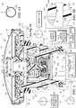
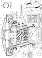
- a fuel cap 10 in accordance with the present disclosure includes a filler-neck closure 12 configured to mate with a fuel-tank filler neck 14 associated with a fuel tank 11 to form a sealed vapor-transfer chamber 16 therebetween as suggested in Figs. 1 , 4 , and 5 .
- Filler neck 14 is formed to include a vent port 18 arranged to open into sealed vapor-transfer chamber 16 and coupled in fluid communication with a fuel vapor recovery canister 22 via a vapor conduit 20 as suggested in Figs. 2 , 4 , and 5 .
- a fuel cap 110 in accordance with another embodiment of the present disclosure is illustrated in Figs. 6-10 .
- a valve mover 24 included in fuel cap 10 moves a vacuum-relief valve 26 also included in fuel cap 10 and mounted for movement in a flow path 34P, 34V, 341, 343 formed in filler-neck closure 12 from a normally closed position shown in Fig. 4 to an opened position shown in Fig. 5 in response to rotation of a closure cover 28 included in fuel cap 10 in a counterclockwise cap-removal direction as suggested in Figs. 4A and 5A .
- pressurized fuel vapor extant in a fuel tank 11 coupled to fuel-tank filler neck 14 can flow through a fuel-conducting passageway 13 formed in fuel-tank filler neck 14 and then, in sequence, through chambers and channels formed in filler-neck closure 12, sealed vapor-transfer chamber 16, vent port 18 formed in filler neck 14, and vapor conduit 20 to reach fuel vapor recovery canister 22 without being discharged through fuel cap 10 to the surrounding atmosphere.
- a fuel vapor transfer system 100 in accordance with the present disclosure comprises a fuel cap 10, a fuel-tank filler neck 14 formed to include a fuel-conducting passageway 13 sized to receive fuel cap 10 and a vent port 18 arranged to open into fuel-conducting passageway 13, a fuel vapor recovery canister 22, and a vapor conduit 20 arranged to interconnect vent port 18 and fuel vapor recovery canister 22 in fluid communication as suggested in Figs. 4 and 5 .
- any pressurized fuel vapor extant in fuel-conducting passageway 13 of filler neck 14 will flow through chambers and channels formed in fuel cap 10 into a sealed vapor-transfer chamber 16 formed between fuel cap 10 and fuel-tank filler neck 14 when fuel cap 10 is mounted in filler neck 14 to close a filler-neck mouth 14M opening into fuel-conducting passageway 13 and when vacuum-relief valve 26 in fuel cap 10 is moved to an opened position as suggested in Fig. 5 .
- the pressurized fuel vapor will exit sealed vapor-transfer chamber 16 through vent port 18 and flow to fuel vapor recovery canister 22 through vapor conduit 20.
- Vacuum-relief valve 26 is configured to provide means for regulating the flow of fuel vapor and air through fuel cap 10 and between fuel-tank filler neck 14 and a fuel vapor recovery canister 22 associated with fuel-tank filler neck 14 and exposed to the surrounding atmosphere. Vacuum-relief valve 26 moves in a flow path formed in fuel cap 10 from a closed position shown in Fig. 4 to block flow of fuel vapor or air between fuel vapor recovery canister 22 and fuel-tank filler neck 14 to an opened position shown in Fig. 5 to allow flow of fuel vapor or air between fuel vapor recovery canister 22 and fuel-tank filler neck 14 either when: (1) the level of negative tank pressure (i.e.
- closure cover 28 of fuel cap 10 is turned in a counterclockwise cap-removal direction by a user during a tank-refueling activity.
- a suction force is applied to the underside of vacuum-relief valve by negative pressure extant in fuel tank 11 and such a suction force pulls vacuum-relief valve 26 downwardly from a closed position shown in Fig.
- Fuel cap 10 illustratively comprises a filler-neck closure 12, a closure cover 28 arranged to rotate about an axis of rotation 28A relative to filler-neck closure 12, and a valve mover 24 coupled to closure cover 28 and filler-neck closure 12 as suggested in Figs. 3A , 4 , and 5 .
- a closure mover 70 is coupled to closure cover 28, filler-neck closure 12, and valve mover 24.
- closure mover 70 to cause filler-neck closure 12 to rotate relative to filler neck 14 about axis of rotation 28A to cause filler-neck closure 12 to mate with filler neck 14 and close the filler-neck mouth 14M opening into fuel-conducting passageway 13 formed in filler neck 12.
- valve mover 24 to cause valve mover 24 to rotate about axis of rotation 28A and move a vacuum-relief valve 26 to an opened position so that pressurized fuel vapor in fuel-tank filler neck 14 can flow in filler-neck closure 12 past the opened vacuum-relief valve 26 and then through sealed vapor-transfer chamber 16, vent port 18, vapor conduit 20, and fuel vapor recovery canister 22 and (2) to filler-neck closure 12 to cause filler-neck closure 12 to rotate about axis of rotation 28A relative to fuel-tank filler neck 14 and break a liquid fuel and fuel vapor seal formed therebetween so that filler-neck closure 12 is disengaged from fuel-tank filler neck 14 to open the filler-neck mouth 14M opening into fuel-conducting passageway 13.
- U.S. Patent No. 8,567,628 for disclosure relating to apparatus for rotating a filler-neck closure in clockwise direction relative to a filler neck during cap installation and for rotating a valve mover to move a vent valve to an opened position without rotating a filler-neck closure during an early stage of cap removal.
- U.S. Patent No. 5,108,001 for disclosure relating to apparatus for opening a vent valve in a fuel cap during removal of the fuel cap from a filler neck.
- fuel cap 10 includes components shown in Figs. 3A and 3B .
- fuel cap 10 comprises (from bottom to top): a lower O-ring seal 30, an upper O-ring seal 32, a closure body 34 configured to mate with fuel-tank filler neck 14 and carry lower and upper O-ring seals 30, 32, a vacuum-relief valve 26 comprising seven components, a valve-mover spring 38, valve mover 24, handgrip retainer ring 40, a body cap 42, a torque-transmission ring 44 associated with closure body 34, a torque converter 46 associated with valve mover 24 and with torque-transmission ring 44, a converter cap 48, a converter-drive plate 50, and a handgrip 52.
- handgrip 52, converter-drive plate 50, and handgrip-retainer ring 40 cooperate to form closure cover 28 as suggested in Fig. 3A .
- a vertical sleeve 461 included in torque converter 46, converter cap 48, and a base 34B configured to carry lower and upper O-ring seals 30, 32 cooperate to form closure body 34 as suggested in Fig. 3A .
- vacuum-relief valve 26 is configured to perform vacuum-relief and pressure-relief functions and comprises (from bottom to top) a first bottom spring-mount plate 260, a first spring 261, a second bottom spring-mount plate 262, a second spring 263, a first top spring-mount plate 264, a round first valve member 265 formed to include a central stem-receiving aperture 266 and associated with first spring 261, and a button 267 adapted to engage and be moved by valve mover 24 and formed to include a round second valve member 268 associated with second spring 263 and a guide stem 269 coupled to the underside of round second valve member 268 as suggested in Fig. 3A .
- Filler-neck closure 12 includes a closure body 34 adapted to be extended into a fuel-conducting passageway 13 formed in a fuel-tank filler neck 14 as suggested in Figs. 4 and 5 .
- Closure body 34 includes a base 34B formed to include a vent aperture 34V adapted to communicate with the fuel-conducting passageway 13 formed in fuel-tank filler neck 14 when closure body 34 is mounted on the fuel-tank filler neck 14.
- Closure body 34 is also formed to include an interior chamber 341 arranged to lie in fluid communication with the vent aperture 34V formed in closure body 34.
- base 34B of closure body 34 includes a lower sleeve 341 arranged to carry lower O-ring seal 30, a chamber floor 34F coupled to a top end of lower sleeve 341 and formed to include vent aperture 34V, an upper sleeve 342 arranged to extend upwardly from chamber floor 34F and in alignment with lower sleeve 341, and a chamber ceiling 34C coupled to a top end of lower sleeve 341.
- Chamber floor 34F, upper sleeve 342, and chamber ceiling 34C cooperate to define an interior chamber 341 formed in closure body 34 to communicate with vent aperture 34V and an open passageway 34P bounded by lower sleeve 341 and chamber floor 34F.
- Body cap 42, vertical sleeve 461 of torque converter 46, and converter cap 48 cooperate to define chamber ceiling 34C in an illustrative embodiment.
- Filler-neck closure 12 also includes an upper O-ring seal 32 arranged to surround and mate with closure body 34 and adapted to mate with fuel-tank filler neck 14 as suggested in Figs. 4 and 5 .
- Upper O-ring seal 32 cooperates with closure body 34 to close a filler-neck mouth 14M opening into a fuel-conducting passageway 13 formed in the fuel-tank filler neck 14.
- Filler-neck closure 12 also includes a vacuum-relief valve 26 mounted in the closure body 34 for movement relative to the closure body 34 from a normally closed position blocking flow of pressurized fuel vapor extant in the fuel-tank filler neck 14 through the vent aperture 34V into the interior chamber 341 of the closure body 34 as shown in Fig. 4 to an opened position shown, for example, in Fig. 5 .
- a vacuum-relief valve 26 mounted in the closure body 34 for movement relative to the closure body 34 from a normally closed position blocking flow of pressurized fuel vapor extant in the fuel-tank filler neck 14 through the vent aperture 34V into the interior chamber 341 of the closure body 34 as shown in Fig. 4 to an opened position shown, for example, in Fig. 5 .
- In the opened position air is allowed to flow from the atmosphere into the fuel-tank filler neck 14 via fuel vapor recovery canister 22, vapor conduit 20, vent port 18, sealed vapor-transfer chamber 16, vent channel 343, interior chamber 341, vent aperture 34V, and open passageway
- Closure cover 28 is arranged to overlie the filler-neck closure 12 and to be gripped by a user as suggested in Figs. 4 and 5 . Closure cover 28 is supported for rotational movement about axis of rotation 28A relative to the filler-neck closure 12.
- Valve mover 24 is coupled to the closure cover 28 using any suitable means (e.g. closure mover 70) and to the vacuum-relief valve 26 as suggested in Figs. 4 and 5 .
- Valve mover 24 is arranged to move the vacuum-relief valve 26 from the normally closed position shown in Fig. 4 to the opened position shown in Fig. 5 in response to movement of the closure cover 28 about axis of rotation 28A relative to the filler-neck closure 12.
- Closure body 34 also includes a side wall 341, 342 adapted to be surrounded by an interior surface of the fuel-tank filler neck 14 when the closure body 34 mates with the fuel-tank filler neck 14 and a portion 342 of the side wall 341, 342 of the closure body 34 is formed to include a vent channel 343 as suggested in Figs. 4 and 5 .
- Vent channel 343 has a channel inlet 344 opening into the interior chamber 341 formed in the closure body 34 and a channel outlet 345 adapted to open into the sealed vapor-transfer chamber 16 defined between filler-neck closure 12 and fuel-tank filler neck 14 when the closure body 34 and the upper O-ring seal 32 mate with the fuel-tank filler neck 14 to close the filler-neck mouth 14M opening into the fuel-conducting passageway 13 formed in the fuel-tank filler neck 14.
- Closure body 34 includes an upper portion 34U adjacent to the closure cover 28, a lower portion 34L arranged to lie in spaced-apart relation to the upper portion 34U, and a middle portion 34M located between the upper and lower portions as suggested in Figs. 3B , 4 , and 5 .
- Upper O-ring seal 32 is coupled to the middle portion 34M of the closure body 34.
- Filler-neck closure 12 further includes a lower O-ring seal 30 coupled to the lower portion 34L of the closure body 34 to locate the upper O-ring seal 32 between a top wall of the closure cover 38 and the lower O-ring seal 30.
- Lower O-ring seal 30 is configured to provide means for sealing against an interior surface of the fuel-tank filler neck 14 when the closure body 34 is mounted on the fuel-tank filler neck 14 to close the filler-neck mouth 14M to cooperate with the upper O-ring seal 32 to establish a sealed vapor-transfer chamber 16 bounded by a portion of the side wall included in the middle portion 34M of the closure body 34 and formed to include the channel outlet 345, the upper O-ring seal 32, a portion of the interior surface of the fuel-tank filler neck 14, and the lower O-ring seal 30 so that any pressurized fuel vapor that is discharged from the vent channel 343 formed in the closure body 34 through the channel outlet 345 flows into the sealed vapor-transfer chamber 16 provided outside the closure body 34 without flowing directly to the atmosphere
- Fuel-tank filler neck 14 is adapted to be coupled in fluid communication to a fuel tank 11 and formed to include a fuel-conducting passageway 13 as suggested in Figs. 4 and 5 .
- Upper and lower O-ring seals 32, 30 are mounted on the closure body 34 and arranged to engage an interior surface of the fuel-tank filler neck 14 when the closure body 34 and upper O-ring seal 32 mate with the fuel-tank filler neck 14 to establish a sealed vapor-transfer chamber 16 bounded by the portion of the side wall included in the middle portion 34M of the closure body 34 and formed to include the channel outlet 345, the upper O-ring seal 32, a portion of the interior surface of the fuel-tank filler neck 14, and the lower O-ring seal 30.
- Fuel-tank filler neck 14 is formed to include a vent port 18 opening into the sealed vapor-transfer chamber 16.
- a vapor conduit 20 is configured to conduct pressurized fuel vapor discharged from the sealed vapor-transfer chamber 16 into the vent port 18 formed in the fuel-tank filler neck 14 to a vapor-recovery canister 22.
- the sealed vapor-transfer chamber 16 has an annular shape and surrounds the closure body 34 of the filler-neck closure 12 in illustrative embodiments.
- Valve mover 24 is arranged to extend into the interior chamber 341 formed in the closure body 34 and to move in the interior chamber 341 relative to the closure body 34.
- Valve mover 24 includes a plate 241 mounted for up-and-down movement in the interior chamber 341 between the chamber ceiling 34C and the chamber floor 34F, a plunger 242 coupled to an underside of the plate 241 to move therewith and formed to include a distal tip 243 arranged to engage the vacuum-relief valve 26 when the vacuum-relief valve 26 occupies the normally closed position.
- Valve mover 24 also includes an upstanding sleeve 244 coupled to plate 241 and arranged to move up-and-down inside a chamber 461C provided in a sleeve 461 included in torque converter 46.
- valve mover 24 This up-and-down lost-motion movement of valve mover 24 relative to torque converter 46 allows upward movement of a second valve member 268 to an opened position separated from a first valve member 265 when exposed to pressurized fuel vapor extant in the open passageway 34P formed in closure body 34 to all pressurized fuel vapor from fuel tank 11 to pass through a central stem-receiving aperture 266 formed in second valve member 265 and flow through sealed vapor-transfer chamber 16 to reach fuel vapor recovery canister 22.
- Valve mover 24 also includes means for moving the plunger 242 downwardly relative to closure body 34 to move the vacuum-relief valve 26 from the normally closed position shown in Fig. 4 to an opened position shown in Fig. 5 in response to rotation of the closure cover 28 in a counterclockwise cap-removal direction about an axis of rotation 28A relative to the closure body 34 while the closure body 34 and the upper O-ring seal 32 mate with the fuel-tank filler neck 14 and the lower O-ring seal 30 mates with the fuel-tank filler neck 14 to form the sealed vapor-transfer chamber 16.
- any pressurized fuel vapor extant in the fuel-conducting passageway 13 formed in the fuel-tank filler neck 14 is vented through the vent aperture 34V formed in the closure body 34, past the opened vacuum-relief valve 26 and into the interior chamber 341, through the vent channel 343 formed in the closure body 34 and into the sealed vapor-transfer chamber 16 provided outside of the closure body 34, and then through the vent port 18 formed in the fuel-tank filler neck 14 and into the vapor conduit 20 for delivery to the vapor-recovery canister 22 without disrupting movement of the vacuum-relief valve 26 to the opened position in response to exposure of the vacuum-relief valve 26 to fuel vapor extant in the fuel-tank filler neck 1.
- Closure body 34 includes a chamber floor 34F formed to include the vent aperture 34V.
- the spring means 38 is arranged to engage an upwardly facing surface included in the chamber floor 34F and arranged to define a boundary of the interior chamber 341.
- the vacuum-relief valve 26 is arranged to engage a downwardly facing surface included in the chamber floor 34F upon movement of the vacuum-relief valve 26 to assume the normally closed position.
- the spring means 38 is formed to include open space through which pressurized fuel vapor flows as the pressurized fuel vapor flows through the interior chamber 341 from the vent aperture 18 formed in the chamber floor 34F to the channel inlet 344 formed in the side wall of the closure body 34 as suggested in Fig. 5 .
- Closure body 34 further includes an annular valve seat 34S arranged to surround the vent aperture 34V and lie outside the interior chamber 341 as suggested in Figs. 4 and 5 .
- Vacuum-relief valve 26 includes a first valve member 265 arranged to engage the annular valve seat 34S when the vacuum-relief valve 26 is moved to assume the closed position and formed to include a central stem-receiving aperture 266, a first position-control spring system 260, 261, 264 coupled to the closure body 34 and arranged to urge the first valve member 265 normally to engage the annular valve seat 34S, a second valve member 268 arranged to lie between the valve mover 24 and the first valve member 265, a guide stem 269 coupled to the second valve member 268 and arranged to extend through the central stem-receiving aperture 266 formed in the first valve member 265, and a second position-control spring system 262, 263 coupled to the second valve member 268 and the guide stem 264 and arranged to urge the second valve member 268 normally to engage the first valve
- the plunger 242 is arranged to move in the interior chamber 341 formed in the closure body 34 to engage the second valve member 268 of the vacuum-relief valve 26 to move the vacuum-relief valve 26 from the normally closed position shown in Fig. 4 to the opened position shown in Fig. 5 in response to rotation of the closure cover 28 in the counterclockwise cap-removal direction about the axis of rotation 28A.
- a coiled compression spring 38 is located in the interior chamber 341 of the closure body 34 as suggested in Figs. 4 and 5 .
- the coiled compression spring 38 is arranged to surround the plunger 242 of the valve mover 24 and engage the chamber floor 34F of the closure body 34 and the plate 241 of the valve mover 24.
- the coiled compression spring 38 is formed to include open space through which pressurized fuel vapor flows as pressurized fuel vapor flows through the interior chamber 341 from the vent aperture 34V formed in the chamber floor 34F to the channel inlet 343 formed in the side wall of the closure body 34 as suggested in Fig. 5 .
- Filler-neck closure 12 further includes an exterior thread coupled to an exterior surface of the portion of the side wall included in the middle portion 34M of the closure body 34 as suggested in Figs. 3A , 4 , and 5 .
- the channel outlet 345 is formed to lie in the exterior thread as suggested in Figs. 4 and 5 .
- the vacuum-relief valve 26 includes a large-diameter first valve member 265 formed to include a topside exterior surface facing upwardly toward the closure cover 28, an underside exterior surface facing downwardly away from the closure cover 28, and a central stem-receiving aperture 266 having an opening in each of the topside and underside exterior surfaces.
- the first position-control spring system 260, 261, 264 is coupled to the closure body 34 and arranged to engage the underside exterior surface of the large-diameter first valve member 265 yieldably to urge the large-diameter first valve member 265 to engage an annular valve seat 34S formed in the closure body 34 to surround the vent aperture 34V.
- a small-diameter second valve member 268 is arranged to lie between the large-diameter first valve member 265 and the valve mover 24.
- a guide stem 269 is coupled to an underside of the small-diameter second valve member 268 and to extend downwardly through the central stem-receiving aperture 266 formed in the large-diameter first valve member 265 to allow relative movement between the small-diameter and large-diameter valve members 268, 265.
- a second position-control spring system 262. 263 is coupled to the large-diameter valve member 265 and the guide stem 269.
- the second position-control spring system is configured yieldably to urge the small-diameter second valve member 268 to engage the topside exterior surface of the large-diameter first valve member 265 normally to block flow of pressurized fuel vapor into the interior chamber 341 formed in the closure body 34 through the vent aperture 34V until the underside of the small-diameter second valve member 268 is exposed to fuel vapor extant in the valve aperture 34V formed in the closure body 34 and characterized by positive pressure in excess of a predetermined positive pressure.
- Valve mover 24 includes a plunger 242 located in the interior chamber 341 formed in the closure body 34 as suggested in Figs. 4 and 5 .
- Valve mover 34 is arranged to engage a topside exterior surface of the small-diameter second valve member 268 when the large-diameter first valve member 265 occupies a normally closed position engaging the annular valve seat 34S to block flow of fuel vapor through the vent aperture 34V and to move downwardly in the interior chamber 341 away from the closure cover 28 to move the large-diameter first valve member 265 to disengage the annular valve seat 34S to cause the vacuum-relief valve 26 to move from the normally closed position shown in Fig. 4 to an opened position shown in Fig. 5 in response to movement of the closure cover 28 in a counterclockwise cap-removal direction relative to the closure body 34.
- Closure body 34 includes a chamber floor 34F formed to include the vent aperture 34V and define an annular valve seat 34S arranged to surround the vent aperture 34V and mate with the vacuum-relief valve 26 when the vacuum-relief valve 26 is in the normally closed position as suggested in Fig. 4 .
- Closure body 34 also includes a sleeve 342 arranged to extend upwardly from the chamber floor 34F to define a portion of the side wall included in the middle portion 34M of the closure body 34 and formed to include the vent channel 343.
- Closure body 34 also includes a chamber ceiling 34C coupled to the sleeve 342 and arranged to lie in spaced-apart relation to the chamber floor 34F to define the interior chamber 341 therebetween.
- Valve mover 24 is mounted for up-and-down movement in the interior chamber 341 formed in the closure body 34 (and in chamber 461C formed in sleeve 461 of torque converter 46) from a raised position arranged to lie in close proximity to the closure cover 28 in a downward direction away from the closure cover 28 toward the chamber floor 34F to a lowered position arranged to engage the vacuum-relief valve 26 and move the vacuum-relief valve 26 from the normally closed position to the opened position.
- the spring means 38 is located in the interior chamber 341 for yieldably urging the valve mover 24 from the opened position toward the normally closed position without blocking flow of pressurized fuel vapor entering the interior chamber 341 through the vent aperture 34V formed in the floor 34F from exiting the interior chamber 341 through the vent channel 343 formed in the side wall.
- the spring means 38 is a helically wound coiled compression spring formed to include a helically winding gap through which pressurized fuel vapor flows during passage through the interior chamber 341 from the vent aperture 34V formed in the chamber floor 34F to the vent channel 343 formed in the side wall.
- the valve mover 24 includes a horizontal plate 241 arranged for up-and-down movement in a region of the interior chamber 341 bounded by the sleeve 342, an upstanding sleeve 244 coupled to a topside of the horizontal plate 241 and arranged to extend upwardly toward a top wall of the closure cover 28, and a depending plunger 242 coupled to an underside of the horizontal plate 241 and arranged to extend downwardly toward the vacuum-relief valve 26 through a cavity formed in the spring means 38.
- Closure body 34 includes a side wall arranged to lie between the upper and lower O-ring seals 32, 30 and to be surrounded by a fuel-tank filler neck 14 when the filler-neck closure 12 is mounted on the fuel-tank filler neck 14 as suggested in Figs. 4 and 5 .
- Closure body 34 is formed to include an interior chamber 341, a vent aperture 34V opening into the interior chamber 341 and adapted to communicate with a fuel-conducting passageway 13 formed in a fuel-tank filler neck 14 when the filler-neck closure 12 is mounted on the fuel-tank filler neck 14, and an annular valve seat 34S located outside of the interior chamber 341 and arranged to surround the vent aperture 34V.
- Filler-neck closure also includes a vacuum-relief valve 26 mounted in the closure body 34 for movement relative to the closure body 34 from a normally closed position blocking flow of pressurized fuel vapor extant in the fuel-tank filler neck 14 through the vent aperture 34V into the interior chamber 341 of the closure body 34 to an opened position allowing flow of air into the fuel-tank filler neck 14 in response to exposure of the vacuum-relief valve 26 to fuel vapor extant in the fuel-tank filler neck 14.
- a vacuum-relief valve 26 mounted in the closure body 34 for movement relative to the closure body 34 from a normally closed position blocking flow of pressurized fuel vapor extant in the fuel-tank filler neck 14 through the vent aperture 34V into the interior chamber 341 of the closure body 34 to an opened position allowing flow of air into the fuel-tank filler neck 14 in response to exposure of the vacuum-relief valve 26 to fuel vapor extant in the fuel-tank filler neck 14.
- the upper O-ring seal 32, the lower O-ring seal 30, and the side wall 341, 342 therebetween cooperate to form means for cooperating with the fuel-tank filler neck 14 to form a sealed vapor-transfer chamber 16 when the filler-neck closure 12 is mounted on the fuel-tank filler neck 14.
- the side wall 341, 342 of the closure body 34 is formed to include a vent channel 343 to conduct pressurized fuel vapor that has been admitted into the interior chamber 341 through the vent aperture 34V when the vacuum-relief valve 26 is moved to the opened position into the sealed vapor-transfer chamber 16.
- Fuel-tank filler neck 14 is formed to include a vent port 18 opening into the sealed vapor-transfer chamber 16 to communicate with pressurized fuel vapor extant therein as suggested in Figs. 4 and 5 .
- a vapor conduit 20 is configured to conduct pressurized fuel vapor discharged from the sealed vapor-transfer chamber 16 into the vent port 18 to a vapor-recovery canister 22.
- Fuel-tank filler neck 14 includes a threaded section as suggested in Figs. 4 and 5 .
- Closure body 34 includes a threaded section configured to mate with the threaded section of the filler neck 14 to retain the filler-neck closure 12 in a mounted position in the fuel-conducting passageway 13 formed in the fuel-tank filler neck 14.
- the threaded section of the closure body 34 is formed to include a channel outlet 345 opening into the vent channel 343 and communicating with the sealed vapor-transfer chamber 16.
- Fuel-tank filler neck 14 is formed to include a filler-neck mouth 14M opening into the fuel-conducting passageway 13 as suggested in Figs. 4 and 5 .
- the vent port 18 is arranged to lie in spaced-apart relation to the filler-neck mouth 14M to locate the threaded section of the fuel-tank filler neck 14 therebetween.
- a closure mover 70 is included in fuel cap 10 to transmit torque applied to closure cover 28 to filler-neck closure 12 to cause filler-neck closure 12 to turn in fuel-conducting passageway 13 formed in fuel-tank filler neck 14 during filler-neck closure 12 installation in or removal from fuel-tank filler neck 14.
- Closure mover 70 comprises torque converter 46, torque-transmission ring 44, and a series of deflectable motion-control arms 43 coupled to an upper portion 34U of closure body 34 as shown, for example, in Figs. 3A and 4 .
- Converter-drive plate 50 in closure cover 28 includes a drive flange 501 formed to include post receiver 502 sized to receive upstanding first and second posts 462, 463 included in torque converter 46 along with upstanding sleeve 461 as suggested in Figs. 3A and 4 .
- Torque converter 46 is configured to mate with torque-transmission ring 44 so that ring 44 rotates about axis of rotation 28A in response to rotation of closure cover 28 about axis of rotation 28A.
- Torque-converter 46 is also configured to include a cam system for applying torque to valve mover 24 to cause valve mover 24 to rotate about axis of rotation 28 in response to rotation of torque-transmission ring 44 during an early stage of removal of fuel cap 10 from fuel-tank filler neck 14.
- a fuel cap 110 in accordance with a second embodiment of the present disclosure includes a filler-neck closure 112 adapted to move relative to a fuel-tank filler neck 14 and close a mouth 14M opening into a fuel-conducting passageway 13 formed in the filler neck 14, and a closure cover 128 adapted to be gripped by a user and rotated about a vertical axis of rotation 128A relative to the filler-tank fuel neck 14 as suggested in Figs. 6-10 .
- a closure mover 123 is coupled to the closure cover 128 and the filler-neck closure 112 and configured to transmit torque applied to the closure cover 128 to the filler-neck closure 12 using any suitable means.
- Filler-neck closure 112 includes a closure body 134 and a pressure-relief valve 60 coupled to the closure body 34 and configured to vent excessive pressurized fuel vapor from the fuel-tank filler neck 14 to atmosphere via a sealed vapor-transport chamber 116 described herein to a fuel vapor recovery canister 22.
- the filler-neck closure 112 also includes a vacuum-relief valve 126 coupled to the closure body 134 and configured normally to dissipate vacuum in the fuel tank 11 by admitting atmosphere that has passed through fuel vapor recovery canister 22 into the filler neck 14 and fuel tank 11.
- Fuel cap 110 further includes a pair of O-ring seals 30, 32 that are mounted on the closure body 134 and arranged to engage the fuel-tank filler neck 14 to create a sealed vapor-transfer chamber 116 that is located in an annular space formed between the closure body 134 of the filler-neck closure 112 and the fuel-tank filler neck 14.
- the sealed vapor-transfer chamber 116 created by the O-ring seals 30, 32 in cooperation with the closure body 134 and filler neck 14 is sealed off from the atmosphere around the fuel cap 10 and filler neck 14 but is connected to a fuel vapor recovery canister 22 spaced apart from the fuel-tank filler neck 14 by a vapor conduit 20.
- the sealed vapor-transfer chamber 116 receives pressurized fuel vapor from the fuel tank 11 and conducts pressurized fuel vapor to the fuel vapor recovery canister 20 through the vapor conduit 20 without discharging fuel vapor directly to the atmosphere through the mouth 14M of the filler neck 14.
- Fuel cap 110 further includes a valve mover 124 coupled to the closure cover 128 to provide means for opening the vacuum-relief valve 26 in response to rotation of the closure cover 128 in a counterclockwise cap-removal direction by a user so that pressurized fuel vapor in the fuel-tank filler neck 14 is vented to the fuel vapor recovery canister 22, in sequence, through the opened vacuum-relief valve 26, the sealed vapor-transfer chamber 116, and vapor conduit 20 prior to breaking a sealed connection established between the filler-neck closure 112 and the fuel-tank filler neck 14.
- a valve mover 124 coupled to the closure cover 128 to provide means for opening the vacuum-relief valve 26 in response to rotation of the closure cover 128 in a counterclockwise cap-removal direction by a user so that pressurized fuel vapor in the fuel-tank filler neck 14 is vented to the fuel vapor recovery canister 22, in sequence, through the opened vacuum-relief valve 26, the sealed vapor-transfer chamber 116, and
- the vacuum-relief valve 126 is positioned to lie in the closure body 134 to lie laterally alongside and in spaced-apart relation to the pressure-relief valve 60 and in spaced-apart relation to a vertical axis of rotation 128A associated with the rotatable closure cover 128.
- the valve mover 124 is configured to convert rotary movement of the closure cover 128 into downward movement of the vacuum-relief valve 126 relative to the closure body 134.
- Application of a downward force by the valve mover 124 to the vacuum-relief valve 126 causes the vacuum-relief valve 126 to move downwardly in a passageway formed in the closure body 134 from a normally closed position to an opened position and act to provide pressure relief to vent pressurized fuel vapor from the fuel tank 11 to the sealed vapor-transfer chamber 116 and the fuel vapor recovery canister 22 via the vapor conduit 20 during removal of the fuel cap 10 from the filler neck 14 but before separation of the filler-neck closure 112 from the filler neck 14 so that this vented pressurized fuel vapor flows to the fuel vapor recovery canister 22 instead of directly to the atmosphere.
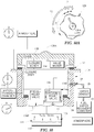
- Vacuum-relief valve 126 is mounted for movement in an interior chamber 1341 formed in closure body 134 also included in filler-neck closure 112 as shown diagrammatically in Fig. 9 and 10 .
- Vacuum-relief valve 126 moves in interior chamber 1341 from a closed position shown in Fig. 9 to block flow of fuel vapor or atmosphere between interior chamber 1341 and fuel tank 11 to an opened position shown in Fig. 10 to allow flow of fuel vapor or atmosphere between interior chamber 1341 and fuel tank 11 either when (1) the level of negative tank pressure (i.e. vacuum) in fuel tank 11 is too high or (2) fuel cap 110 is turned in a cap-removal direction by a user during a tank-refueling activity.
- negative tank pressure i.e. vacuum
- vacuum-relief valve 126 is opened automatically in response to negative pressure (i.e., vacuum conditions) extant in fuel tank 11 to admit atmosphere into filler neck 14 to relieve excess negative tank pressure in fuel tank 11. Atmosphere is introduced into fuel tank 11 after being pulled through a fuel vapor recovery canister 22 and a vapor conduit 20 coupled to the filler neck 14 via a sealed vapor-transfer chamber 16 provided between closure body 134 and filler neck 14.
- negative pressure i.e., vacuum conditions
- vacuum-relief valve 126 is opened automatically during cap removal as part of a tank refueling activity to vent excess pressurized fuel vapor in fuel tank 11 to the fuel vapor recovery canister 22 via sealed vapor-transfer chamber 16 and vapor conduit 20 as suggested in Fig. 10 .
- vacuum-relief valve 126 is configured to be opened automatically by exposure of vacuum-relief valve 126 to sufficient negative tank pressure extant in fuel tank 11 in a pull-down vacuum activation mode and, alternatively, opened automatically by exposure to a downward valve-moving force applied by a valve mover 124 to vacuum-relief valve 126 during rotation of cover 18 about axis of rotation 128A in a cap-removal direction by a user as suggested diagrammatically in Fig. 10 .
- Valve mover 124 is coupled to and positioned to lie between closure cover 128 and vacuum-relief valve 126 in a space provided between closure cover 128 and closure body 134 as shown diagrammatically in Figs. 9 and 10 .
- Valve mover 124 is configured to move (e.g., push) vacuum-relief valve 126 relative to closure body 134 in the interior chamber 1341 formed in closure body 134 from a normally closed position (shown in Fig. 9 ) downwardly to an opened position (shown in Fig.
- Fuel cap 110 also includes a pair of O-ring seals 30, 32 arranged to lie between the rest of the fuel cap 110 and the filler neck 14 to define a sealed vapor-transfer chamber 116 located radially in an annular space provided between the closure body 134 and the filler neck 14 when the fuel cap 110 is mounted on the filler neck 14 as shown in Fig. 9 .
- O-ring seals 30, 32 provide means for cooperating with closure body 134 and fuel-tank filler neck 14 to define and maintain sealed vapor-transfer chamber 116 between closure body 134 and filler neck 14 during a first stage of rotation of cover 128 (illustratively corresponding to arrow 71 in Fig. 9A ) relative to the filler neck 14.
- sealed vapor-transfer chamber 116 (i) receives pressurized vapor vented past the temporarily opened vacuum-relief valve 126 as suggested by the pressure gauges corresponding to filler neck 14 and vapor-transfer chamber 116 and (ii) conducts pressurized vapor from vapor-transfer chamber 116 into vapor conduit 20 extending from a vent port 18 formed in filler neck 14 before mouth 14M of filler neck 14 is reopened to atmosphere in response to a second stage of rotation of closure cover 128 relative to filler neck 14.
- vacuum-relief valve 126 is shown in a normally closed position in Fig. 9 . Any pressurized fuel vapor extant in fuel tank 11 and fuel-conducting passageway 13 of filler neck 14 is vented past the opened vacuum-relief valve 126 that is opened by valve mover 124 during a first stage of rotation in the cap-removal direction before closure body 134 begins to rotate in a second stage of rotation in the cap-removal direction in which the fuel cap 110 is decoupled from the filler neck 14.
Landscapes
- Engineering & Computer Science (AREA)
- Life Sciences & Earth Sciences (AREA)
- Sustainable Development (AREA)
- Sustainable Energy (AREA)
- Chemical & Material Sciences (AREA)
- Combustion & Propulsion (AREA)
- Transportation (AREA)
- Mechanical Engineering (AREA)
- Cooling, Air Intake And Gas Exhaust, And Fuel Tank Arrangements In Propulsion Units (AREA)
Claims (13)
- Kraftstoffdampfübertragungssystem, aufweisend
einen Einfüllstutzenverschluss (12), aufweisend einen Verschlusskörper (34), welcher ausgelegt ist, in einen kraftstoffleitenden Durchgang (13) erweitert zu sein, welcher in einem Kraftstofftank-Einfüllstutzen (14) ausgebildet ist, wobei der Verschlusskörper (34) ausgebildet ist, um eine Lüftungsöffnung (34V) aufzuweisen, welche ausgelegt ist, mit dem in dem Kraftstofftank-Einfüllstutzen (14) ausgebildeten kraftstoffleitenden Durchgang (13) zu kommunizieren, wenn der Verschlusskörper (34) an dem Kraftstofftank-Einfüllstutzen (14) montiert ist, wobei der Verschlusskörper (34) zudem ausgebildet ist, um eine Innenkammer (34I) aufzuweisen, welche angeordnet ist, um mit der in dem Verschlusskörper (34) ausgebildeten Lüftungsöffnung (34V) in Fluidverbindung zu stehen, wobei der Einfüllstutzenverschluss (12) zudem eine obere O-Ring-Dichtung (32), welche angeordnet ist, um den Verschlusskörper (34) zu umgeben und damit verbunden zu sein, und ausgelegt ist, mit dem Kraftstofftank-Einfüllstutzen (14) verbunden zu sein und mit dem Verschlusskörper (34) zusammenzuwirken, um eine Einfüllstutzen-Mündung zu verschließen, welche sich in den in dem Kraftstofftank-Einfüllstutzen (14) ausgebildeten kraftstoffleitenden Durchgang (13) öffnet, und ein Vakuumentlastungsventil (26) aufweist, welches in dem Verschlusskörper (34) montiert ist zur Bewegung relativ zu dem Verschlusskörper (34) von einer normalerweise verschlossenen Position, welche eine Strömung von in dem Kraftstofftank-Einfüllstutzen (14) verbleibendem unter Druck stehendem Kraftstoffdampf durch die Lüftungsöffnung (34V) in die Innenkammer (34I) des Verschlusskörpers (34) blockiert, zu einer geöffneten Position, welche eine Strömung von Luft aus der Umgebung in den Kraftstofftank-Einfüllstutzen (14) als Reaktion auf ein Aussetzen des Vakuumentlastungsventils (26) einem in dem Kraftstofftank-Einfüllstutzen (14) verbleibenden Kraftstoffdampf ermöglicht,
einen Verschlussdeckel (28), welcher angeordnet ist, um den Einfüllstutzenverschluss (12) zu überlagern und um von einem Nutzer gegriffen und zur Bewegung relativ zu dem Einfüllstutzenverschluss (12) gelagert zu sein, und
eine Ventilbewegungseinrichtung (24), welche mit dem Vakuumentlastungsventil (26) gekoppelt ist und angeordnet ist, um das Vakuumentlastungsventil (26) als Reaktion auf eine Bewegung des Verschlussdeckels (28) relativ zu dem Einfüllstutzenverschluss (12) von der normalerweise verschlossenen Position zu der geöffneten Position zu bewegen, wobei der Verschlusskörper (34) zudem eine Seitenwand aufweist, welche ausgelegt ist, von einer Innenfläche des Kraftstofftank-Einfüllstutzens (14) umgeben zu sein, wenn der Verschlusskörper (34) mit dem Kraftstofftank-Einfüllstutzen (14) verbunden ist, und die Seitenwand des Verschlusskörpers (34) ausgebildet ist, um aufzuweisen einen Lüftungskanal (343) mit einem Kanaleinlass (344), welcher sich in die in dem Verschlusskörper (34) ausgebildete Innenkammer (34I) öffnet, und einem Kanalauslass (345), welcher ausgelegt ist, sich in den in dem Kraftstofftank-Einfüllstutzen (14) ausgebildeten kraftstoffleitenden Durchgang (13) zu öffnen, wenn der Verschlusskörper (34) und die obere O-Ring-Dichtung mit dem Kraftstofftank-Einfüllstutzen (14) verbunden sind, um die Einfüllstutzen-Mündung zu verschließen, welche sich in den in dem Kraftstofftank-Einfüllstutzen (14) ausgebildeten kraftstoffleitenden Durchgang (13) öffnet. - Kraftstoffdampfübertragungssystem nach Anspruch 1, wobei der Verschlusskörper (34) einen zu dem Verschlussdeckel (28) benachbarten oberen Abschnitt, einen unteren Abschnitt, welcher angeordnet ist, um in einem beabstandeten Verhältnis zu dem oberen Abschnitt zu stehen, und einen mittleren Abschnitt aufweist, welcher sich zwischen dem oberen und dem unteren Abschnitt befindet, die obere O-Ring-Dichtung (32) mit dem mittleren Abschnitt des Verschlusskörpers (34) gekoppelt ist, der Einfüllstutzenverschluss (12) ferner eine untere O-Ring-Dichtung (30) aufweist, welche mit dem unteren Abschnitt des Verschlusskörpers (28) gekoppelt ist, um die obere O-Ring-Dichtung (32) zwischen einer oberen Wand des Verschlussdeckels (28) und der unteren O-Ring-Dichtung (30) zu platzieren, die untere O-Ring-Dichtung (30) eingerichtet ist, um Mittel zur Abdichtung gegen eine Innenfläche des Kraftstofftank-Einfüllstutzens bereitzustellen, wenn der Verschlusskörper (34) an dem Kraftstofftank-Einfüllstutzen (14) montiert ist, um die Einfüllstutzen-Mündung zu verschließen, um mit der oberen O-Ring-Dichtung (32) zusammenzuwirken, um eine abgedichtete Dampfübertragungskammer (16) herzustellen, welche durch einen Abschnitt der Seitenwand, welcher in dem mittleren Abschnitt des Verschlusskörpers (34) enthalten ist und ausgebildet ist, um den Kanalauslass (345) aufzuweisen, die obere O-Ring-Dichtung (30), einen Abschnitt der Innenfläche des Kraftstofftank-Einfüllstutzens (14) und die untere O-Ring-Dichtung (30) begrenzt ist, sodass jeglicher unter Druck stehende Kraftstoffdampf, welcher aus dem in dem Verschlusskörper (34) ausgebildeten Lüftungskanal (343) durch den Kanalauslass (345) abgeführt ist, in die außerhalb des Verschlusskörpers (34) bereitgestellte abgedichtete Dampfübertragungskammer (16) strömt.
- Kraftstoffdampfübertragungssystem nach Anspruch 1 oder 2, ferner aufweisend einen Kraftstofftank-Einfüllstutzen (14), welcher ausgelegt ist, um in Fluidverbindung mit einem Kraftstofftank gekoppelt zu sein und ausgebildet ist, um einen kraftstoffleitenden Durchgang (13) aufzuweisen, wobei die obere und die untere O-Ring-Dichtung, welche an dem Verschlusskörper (34) montiert sind, angeordnet sind, um mit einer Innenfläche des Kraftstofftank-Einfüllstutzens (14) in Wirkverbindung zu gelangen, wenn der Verschlusskörper (34) und die obere O-Ring-Dichtung mit dem Kraftstofftank-Einfüllstutzen (14) verbunden sind, um eine abgedichtete Dampfübertragungskammer (16) herzustellen, welche durch den Abschnitt der Seitenwand, welcher in dem mittleren Abschnitt des Verschlusskörpers (34) enthalten ist und ausgebildet ist, um den Kanalauslass (345) aufzuweisen, die obere O-Ring-Dichtung (32), einen Abschnitt der Innenfläche des Kraftstofftank-Einfüllstutzens und die untere O-Ring-Dichtung (30) begrenzt ist, und wobei der Kraftstofftank-Einfüllstutzen (14) ausgebildet ist, um einen Lüftungsanschluss aufzuweisen, welcher sich in die abgedichtete Dampfübertragungskammer (16) öffnet, und ferner aufweist eine Dampfleitung, welche eingerichtet ist, um aus der abgedichteten Dampfübertragungskammer (16) in den in dem Kraftstofftank-Einfüllstutzen (14) ausgebildeten Lüftungsanschluss abgeführten unter Druck stehenden Kraftstoffdampf zu einem Dampfrückgewinnungskanister zu leiten.
- Kraftstoffdampfübertragungssystem nach Anspruch 1, 2 oder 3, wobei die abgedichtete Dampfübertragungskammer (16) eine Ringform aufweist und den Verschlusskörper (34) des Einfüllstutzenverschlusses (12) umgibt.
- Kraftstoffdampfübertragungssystem nach Anspruch 2, 3 oder 4, wobei die Ventilbewegungseinrichtung (24) angeordnet ist, um sich in die in dem Verschlusskörper (34) ausgebildete Innenkammer (34I) zu erstrecken, und um sich in der Innenkammer (34I) relativ zu dem Verschlusskörper (34) zu bewegen, und die Ventilbewegungseinrichtung (24) eine Platte, welche zur Auf-und-Ab-Bewegung in der Innenkammer (34I) zwischen der Kammerdecke und dem Kammerboden montiert ist, einen Stift, welcher mit einer Unterseite der Platte gekoppelt ist, um sich damit zu bewegen, und ausgebildet ist, um eine distale Spitze aufzuweisen, welche angeordnet ist, um dem Vakuumentlastungsventil (26) zugewandt zu sein, wenn das Vakuumentlastungsventil (26) die normalerweise verschlossene Position besetzt, und Mittel zur Bewegung des Stifts in der Innenkammer (34I) nach unten weg von dem Verschlussdeckel (28) aufweist, um das Vakuumentlastungsventil (26) als Reaktion auf eine Drehung des Verschlussdeckels (28) in einer Kappenabnahmerichtung um eine Drehachse relativ zu dem Verschlusskörper (34) von der normalerweise verschlossenen Position zu einer geöffneten Position zu bewegen, während der Verschlusskörper (34) und die obere O-Ring-Dichtung mit dem Kraftstofftank-Einfüllstutzen (34) verbunden sind und die untere O-Ring-Dichtung mit dem Kraftstofftank-Einfüllstutzen (14) verbunden ist, um die abgedichtete Dampfübertragungskammer (16) zu bilden, um jeglichen in dem in dem Kraftstofftank-Einfüllstutzen (14) ausgebildeten kraftstoffleitenden Durchgang (13) verbleibenden unter Druck stehenden Kraftstoffdampf durch die in dem Verschlusskörper (34) ausgebildete Lüftungsöffnung (34V), über das Vakuumentlastungsventil (26) und in die Innenkammer (34I), durch den in dem Verschlusskörper (34) ausgebildeten Lüftungskanal (343) und in die außerhalb des Verschlusskörpers (34) bereitgestellte abgedichtete Dampfübertragungskammer (16), und durch den in dem Kraftstofftank-Einfüllstutzen (14) ausgebildeten Lüftungsanschluss und in die Dampfleitung zur Beförderung zu dem Dampfübertragungskanister abzulassen, ohne eine Bewegung des Vakuumentlastungsventils (26) zu der geöffneten Position als Reaktion auf ein Aussetzen des Vakuumentlastungsventils (26) einem in dem Kraftstofftank-Einfüllstutzen (14) verbleibenden Kraftstoffdampf zu behindern.
- Kraftstoffdampfübertragungssystem nach Anspruch 5, ferner aufweisend sich in der in dem Verschlusskörper (34) ausgebildeten Innenkammer (34I) befindende Mittel zum federnden Drücken der Ventilbewegungseinrichtung (24), um sich relativ zu dem Verschlusskörper (34) in einer Aufwärtsrichtung in Richtung des Verschlussdeckels (28) zu einer erhobenen inaktiven Position zu bewegen, welche von dem Vakuumentlastungsventil (26) getrennt ist; optional wobei der Verschlusskörper (34) einen Kammerboden aufweist, welcher ausgebildet ist, um die Lüftungsöffnung (34V) aufzuweisen, die Federmittel angeordnet sind, um mit einer nach oben weisenden Fläche in Wirkverbindung zu gelangen, welche in dem Kammerboden enthalten ist und angeordnet ist, um eine Grenze der Innenkammer (34I) zu definieren, und das Vakuumentlastungsventil (26) angeordnet ist, um bei einer Bewegung des Vakuumentlastungsventils (26) mit einer in dem Kammerboden enthaltenen nach unten weisenden Fläche in Wirkverbindung zu gelangen, um die normalerweise verschlossene Position einzunehmen, und die Federmittel ausgebildet sind, um offenen Raum aufzuweisen, durch welchen unter Druck stehender Kraftstoffdampf strömt, wenn der unter Druck stehende Kraftstoffdampf durch die Innenkammer (34I) von der in dem Kammerboden ausgebildeten Lüftungsöffnung (34V) zu dem in der Seitenwand des Verschlusskörpers (34) ausgebildeten Kanaleinlass (344) strömt.
- Kraftstoffdampfübertragungssystem nach Anspruch 5 oder 6, wobei der Verschlusskörper (34) ferner einen ringförmigen Ventilsitz aufweist, welcher angeordnet ist, um die Lüftungsöffnung (34V) zu umgeben und außerhalb der Innenkammer (34I) zu liegen, das Vakuumentlastungsventil (26) ein erstes Ventilelement, welches angeordnet ist, um mit dem ringförmigen Ventilsitz in Wirkverbindung zu gelangen, wenn das Vakuumentlastungsventil (26) bewegt ist, um die verschlossene Position einzunehmen, und ausgebildet ist, um eine mittlere Schaftaufnahmeöffnung aufzuweisen, ein erstes Positionssteuerfedersystem, welches mit dem Verschlusskörper (34) gekoppelt ist und angeordnet ist, um das erste Ventilelement normalerweise zu drücken, um mit dem ringförmigen Ventilsitz in Wirkverbindung zu gelangen, ein zweites Ventilelement, welches angeordnet ist, um zwischen der Ventilbewegungseinrichtung (24) und dem ersten Ventilelement zu liegen, einen Führungsschaft, welcher mit dem ersten Ventilelement gekoppelt ist und angeordnet ist, um sich durch die in dem ersten Ventilelement ausgebildete mittlere Schaftaufnahmeöffnung zu erstrecken, und ein zweites Positionssteuerfedersystem aufweist, welches mit dem ersten Ventilelement und dem Führungsschaft gekoppelt ist und angeordnet ist, um das zweite Ventilelement normalerweise zu drücken, um mit dem ersten Ventilelement in Wirkverbindung zu gelangen, um die mittlere Schaftaufnahmeöffnung zu verschließen, und wobei der Stift angeordnet ist, um sich in der in dem Verschlusskörper (34) ausgebildeten Innenkammer (34I) zu bewegen, um mit dem zweiten Ventilelement des Vakuumentlastungsventils (26) in Wirkverbindung zu gelangen, um das Vakuumentlastungsventil (26) als Reaktion auf eine Drehung des Verschlussdeckels (28) in der Kappenabnahmerichtung um die Drehachse von der normalerweise verschlossenen Position zu der geöffneten Position zu bewegen.
- Kraftstoffdampfübertragungssystem nach Anspruch 7, ferner aufweisend eine Schraubendruckfeder, welche sich in der Innenkammer (34I) des Verschlusskörpers (34) befindet und angeordnet ist, um den Stift der Ventilbewegungseinrichtung (24) zu umgeben und mit dem Kammerboden des Verschlusskörpers (34) und der Platte der Ventilbewegungseinrichtung (24) in Wirkverbindung zu gelangen, und die Schraubenfeder ausgebildet ist, um offenen Raum aufzuweisen, durch welchen unter Druck stehender Kraftstoffdampf strömt, wenn unter Druck stehender Kraftstoffdampf durch die Innenkammer (34I) von der in dem Kammerboden ausgebildeten Lüftungsöffnung (34V) zu dem in der Seitenwand des Verschlusskörpers (34) ausgebildeten Kanalauslass (344) strömt.
- Kraftstoffdampfübertragungssystem nach Anspruch 2, 3, 4, 5, 6, 7 oder 8, wobei der Einfüllstutzenverschluss (12) ferner ein Außengewinde aufweist, welches mit einer Außenfläche des in dem mittleren Abschnitt des Verschlusskörpers (34) enthaltenen Abschnitts der Seitenwand gekoppelt ist, und der Kanalauslass (345) ausgebildet ist, um zwischen der oberen O-Ring-Dichtung (32) und dem Außengewinde zu liegen.
- Kraftstoffdampfübertragungssystem nach Anspruch 2, 4, 5, 6, 7, 8 oder 9, wobei das Vakuumentlastungsventil (26) aufweist ein erstes Ventilelement mit hohem Durchmesser, welches ausgebildet ist, um aufzuweisen eine oberseitige Außenfläche, welche nach oben in Richtung des Verschlussdeckels (28) weist, eine unterseitige Außenfläche, welche nach unten weg von dem Verschlussdeckel (28) weist, und eine mittlere Schaftaufnahmeöffnung mit einer Öffnung sowohl in der oberseitigen als auch in der unterseitigen Außenfläche, ein erstes Positionssteuerfedersystem, welches mit dem Verschlusskörper (34) gekoppelt ist und angeordnet ist, um mit der unterseitigen Außenfläche des ersten Ventilelements mit hohem Durchmesser federnd in Wirkverbindung zu gelangen, um das erste Ventilelement mit hohem Durchmesser zu drücken, um mit einem ringförmigen Ventilsitz in Wirkverbindung zu gelangen, welcher in dem Verschlusskörper (34) ausgebildet ist, um die Lüftungsöffnung (34V) zu umgeben, ein zweites Ventilelement mit geringem Durchmesser, welches angeordnet ist, um zwischen dem ersten Ventilelement mit hohem Durchmesser und der Ventilbewegungseinrichtung (24) zu liegen, einen Führungsschaft, welcher mit einer Unterseite des zweiten Ventilelements mit geringem Durchmesser gekoppelt ist und sich nach unten durch die in dem ersten Ventilelement mit hohem Durchmesser ausgebildete mittlere Schaftaufnahmeöffnung erstreckt, um eine relative Bewegung zwischen den Ventilelementen mit hohem Durchmesser und mit geringem Durchmesser zu ermöglichen, und ein zweites Positionssteuerfedersystem, welches mit dem Ventilelement mit hohem Durchmesser und dem Führungsschaft gekoppelt ist und federnd eingerichtet ist, um das zweite Ventilelement mit geringem Durchmesser zu drücken, um mit der oberseitigen Außenfläche des ersten Ventilelements mit hohem Durchmesser normalerweise in Wirkverbindung zu gelangen, um eine Strömung von unter Druck stehendem Kraftstoffdampf in die in dem Verschlusskörper (34) ausgebildete Innenkammer (34I) durch die Lüftungsöffnung (34V) zu blockieren, bis die Unterseite des zweiten Ventilelements mit geringem Durchmesser Kraftstoffdampf ausgesetzt ist, welcher in der in dem Verschlusskörper (34) ausgebildeten Ventilöffnung verbleibt, und die Ventilbewegungseinrichtung (24) aufweist einen Stift, welcher sich in der in dem Verschlusskörper (34) ausgebildeten Innenkammer (34I) befindet und angeordnet ist, um einer oberseitigen Außenfläche des zweiten Ventilelements mit geringem Durchmesser zugewandt zu sein, wenn das erste Ventilelement mit hohem Durchmesser eine normalerweise verschlossene Position besetzt und somit mit dem ringförmigen Ventilsitz in Wirkverbindung gelangt, um eine Strömung von Kraftstoffdampf durch die Lüftungsöffnung (34V) zu blockieren und um sich in der Innenkammer (34I) nach unten weg von dem Verschlussdeckel (28) zu bewegen, um das erste Ventilelement mit hohem Durchmesser zu bewegen, um die Wirkverbindung mit dem ringförmigen Ventilsitz aufzuheben, um das Vakuumentlastungsventil (26) zu veranlassen, sich als Reaktion auf eine Bewegung des Verschlusskörpers (28) in einer Kappenabnahmerichtung relativ zu dem Verschlusskörper (34) von der normalerweise verschlossenen Position zu einer geöffneten Position zu bewegen.
- Kraftstoffdampfübertragungssystem nach einem der vorhergehenden Ansprüche, wobei der Verschlusskörper (34) einen Kammerboden aufweist, welcher ausgebildet ist, um die Lüftungsöffnung (34V) aufzuweisen und einen ringförmigen Ventilsitz zu definieren, welcher angeordnet ist, um die Lüftungsöffnung (34V) zu umgeben und mit dem Vakuumentlastungsventil (26) verbunden zu sein, wenn das Vakuumentlastungsventil (26) in der normalerweise verschlossenen Position ist, eine Hülse, welche angeordnet ist, um sich von dem Kammerboden aus nach oben zu erstrecken, um einen Abschnitt der Seitenwand zu definieren, welcher in dem mittleren Abschnitt des Verschlusskörpers (34) enthalten ist und ausgebildet ist, um den Lüftungskanal (343) aufzuweisen, und eine Kammerdecke, welche mit der Hülse gekoppelt ist und angeordnet ist, um in einem beabstandeten Verhältnis zu dem Kammerboden zu stehen, um die Innenkammer (34I) dazwischen zu definieren.
- Kraftstoffdampfübertragungssystem nach Anspruch 11, wobei die Ventilbewegungseinrichtung (24) montiert ist zur Auf-und-Ab-Bewegung in der in dem Verschlusskörper (34) ausgebildeten Innenkammer (34I) von einer erhobenen Position, welche angeordnet ist, um in naher Umgebung des Verschlussdeckels (28) zu liegen, in einer Abwärtsrichtung weg von dem Verschlussdeckel (28) in Richtung des Kammerbodens zu einer gesenkten Position, welche angeordnet ist, um das Vakuumentlastungsventil (26) von der normalerweise verschlossenen Position zu der geöffneten Position zu bewegen; optional wobei das Kraftstoffdampfübertragungssystem ferner sich in der Innenkammer (34I) befindende Federmittel zum federnden Drücken der Ventilbewegungseinrichtung (24) von der geöffneten Position in Richtung der normalerweise verschlossenen Position, ohne ein Austreten einer Strömung von in die Innenkammer (34I) durch die in dem Boden ausgebildete Lüftungsöffnung (34V) eintretendem unter Druck stehendem Kraftstoffdampf aus der Innenkammer (34I) durch den in der Seitenwand ausgebildeten Lüftungskanal (343) zu blockieren, aufweist.
- Kraftstoffdampfübertragungssystem nach Anspruch 12,
wobei die Federmittel eine spiralförmig gewundene Schraubendruckfeder umfassen, welche ausgebildet ist, um einen sich spiralförmig windenden Spalt aufzuweisen, durch welchen unter Druck stehender Kraftstoffdampf beim Durchlaufen der Innenkammer (34I) von der in dem Kammerboden ausgebildeten Lüftungsöffnung (34V) zu dem in der Seitenwand ausgebildeten Lüftungskanal (343) strömt; oder
wobei die Ventilbewegungseinrichtung (24) eine horizontale Platte, welche zur Auf-und-Ab-Bewegung in einem durch die Hülse begrenzten Bereich der Innenkammer (34I) angeordnet ist, einen abstehenden Zapfen, welcher mit einer Oberseite der horizontalen Platte gekoppelt ist und angeordnet ist, um sich nach oben in Richtung einer oberen Wand des Verschlussdeckels (28) zu erstrecken, und einen herabhängenden Stift aufweist, welcher mit einer Unterseite der horizontalen Platte gekoppelt ist und angeordnet ist, um sich durch einen in den Federmitteln ausgebildeten Hohlraum nach unten in Richtung des Vakuumentlastungsventils (26) zu erstrecken.
Applications Claiming Priority (2)
| Application Number | Priority Date | Filing Date | Title |
|---|---|---|---|
| US201361818273P | 2013-05-01 | 2013-05-01 | |
| PCT/US2014/036293 WO2014179524A1 (en) | 2013-05-01 | 2014-05-01 | Fuel vapor transfer system |
Publications (3)
| Publication Number | Publication Date |
|---|---|
| EP2991849A1 EP2991849A1 (de) | 2016-03-09 |
| EP2991849A4 EP2991849A4 (de) | 2016-12-28 |
| EP2991849B1 true EP2991849B1 (de) | 2020-11-11 |
Family
ID=51840913
Family Applications (1)
| Application Number | Title | Priority Date | Filing Date |
|---|---|---|---|
| EP14791463.4A Not-in-force EP2991849B1 (de) | 2013-05-01 | 2014-05-01 | Kraftstoffdampfübertragungssystem |
Country Status (3)
| Country | Link |
|---|---|
| US (1) | US9688135B2 (de) |
| EP (1) | EP2991849B1 (de) |
| WO (1) | WO2014179524A1 (de) |
Families Citing this family (5)
| Publication number | Priority date | Publication date | Assignee | Title |
|---|---|---|---|---|
| CN105805373B (zh) * | 2016-05-03 | 2019-02-12 | 重庆市百科鼎昱科技有限公司 | 一种呼吸阀、油箱盖和油箱 |
| USD823343S1 (en) * | 2017-03-21 | 2018-07-17 | Wilkins Ip, Llc | Impeller housing |
| BR102018067630B1 (pt) * | 2018-09-03 | 2020-10-27 | Miguel Greyde Avila Dias | válvula termodinâmica retentora de vapores e gases e de alívio de pressão e vácuo |
| US11383901B2 (en) * | 2018-12-05 | 2022-07-12 | Bemis Manufacturing Company | Pressure relief cap |
| US12017525B2 (en) | 2021-10-27 | 2024-06-25 | Stant Usa Corp. | Fuel cap |
Family Cites Families (19)
| Publication number | Priority date | Publication date | Assignee | Title |
|---|---|---|---|---|
| US4498493A (en) | 1981-06-24 | 1985-02-12 | Stant Inc. | Pressure valve assembly for a fuel tank filler neck cap |
| US4877146A (en) * | 1986-03-31 | 1989-10-31 | Stant Inc. | Vacuum-controlled vapor recovery system |
| US4736863A (en) | 1986-05-30 | 1988-04-12 | Stant Inc. | Ball-valve fuel cap |
| US4676390A (en) | 1986-07-22 | 1987-06-30 | Stant Inc. | Pressure-release fuel cap |
| US4765505A (en) | 1986-07-22 | 1988-08-23 | Stant Inc. | Delayed actuation fuel cap |
| US4685584A (en) | 1986-09-29 | 1987-08-11 | Stant Inc. | Vented fuel cap with bump and grade seal |
| US4716920A (en) | 1987-01-08 | 1988-01-05 | Stant Inc. | Roll over fuel cap |
| US4913303A (en) | 1987-06-16 | 1990-04-03 | Stant Inc. | Liquid splash control fuel cap |
| US4787529A (en) | 1987-06-16 | 1988-11-29 | Stant Inc. | Vapor-liquid control fuel cap |
| US5108001A (en) * | 1990-07-03 | 1992-04-28 | Stant Inc. | Pressure release vent cap |
| US5183173A (en) | 1991-07-29 | 1993-02-02 | Epicor Industries, Inc. | Auto venting fuel cap |
| GB9705409D0 (en) | 1997-03-15 | 1997-04-30 | Britax Wingard Ltd | Pressure relief valve |
| DE60027304T2 (de) * | 1999-05-17 | 2006-11-09 | Stant Manufacturing Inc., Connersville | Sicherheitsdichtung des schliesselements einer fülltüte für grossbehälter |
| US6561211B2 (en) | 2000-10-19 | 2003-05-13 | Stant Manufacturing Inc. | Fuel tank vent control valve |
| US6481592B2 (en) | 2001-04-23 | 2002-11-19 | Stant Manufacturing Inc. | Fuel tank vent valve |
| US6923224B1 (en) * | 2004-01-15 | 2005-08-02 | Stant Manufacturing Inc. | Closure and vent system for capless filler neck |
| US7131469B2 (en) * | 2005-01-10 | 2006-11-07 | Dunkle Gary L | Outdoor tool fuel cap |
| US7654403B2 (en) | 2005-09-02 | 2010-02-02 | Stant Manufacturing Inc. | Fuel tank vacuum-relief system |
| US8567628B2 (en) * | 2008-10-14 | 2013-10-29 | Stant Usa Corp. | Fuel cap with fuel-tank pressure/vacuum dissipation control system |
-
2014
- 2014-05-01 EP EP14791463.4A patent/EP2991849B1/de not_active Not-in-force
- 2014-05-01 WO PCT/US2014/036293 patent/WO2014179524A1/en not_active Ceased
- 2014-05-01 US US14/266,988 patent/US9688135B2/en active Active
Non-Patent Citations (1)
| Title |
|---|
| None * |
Also Published As
| Publication number | Publication date |
|---|---|
| WO2014179524A1 (en) | 2014-11-06 |
| EP2991849A4 (de) | 2016-12-28 |
| US20140326742A1 (en) | 2014-11-06 |
| EP2991849A1 (de) | 2016-03-09 |
| US9688135B2 (en) | 2017-06-27 |
Similar Documents
| Publication | Publication Date | Title |
|---|---|---|
| US9688135B2 (en) | Fuel vapor transfer system | |
| US6691750B1 (en) | Floating nozzle collar for capless filler neck | |
| US5535772A (en) | Tank venting control system | |
| US4790349A (en) | Tank pressure control system | |
| US4836835A (en) | Vacuum-actuated vapor recovery system | |
| US4714172A (en) | Vapor recovery systems | |
| US4699638A (en) | Two-stage roll-over valve | |
| US4877146A (en) | Vacuum-controlled vapor recovery system | |
| EP0647194B1 (de) | Einfüllstutzen | |
| US4816045A (en) | Vapor recovery system | |
| US8567628B2 (en) | Fuel cap with fuel-tank pressure/vacuum dissipation control system | |
| US10065496B2 (en) | Filler neck closure with drainage system | |
| EP3532330B1 (de) | Druckregler für kraftstofftank | |
| KR20060102510A (ko) | 일체형 증기 벤트/팁핑 밸브 및 증기 저장 조립체 및 그제조 방법 | |
| CN115038605B (zh) | 燃料箱压力调节器 | |
| JPH04224420A (ja) | キヤツプレス車両燃料補給システム | |
| JP6198167B2 (ja) | 圧力解放密閉キャップ | |
| KR20030086413A (ko) | 연료 증기 배기 제어 방법 및 시스템 | |
| CN107231809B (zh) | 容器满溢保护系统 | |
| US8286658B2 (en) | Roll-over valve with shared overfill protection and vacuum relief | |
| JP6625117B2 (ja) | トリガー式通気孔を有する燃料タンクアセンブリ | |
| US6837256B2 (en) | Filler tube mounted fuel tank refueling valve | |
| US6782911B2 (en) | Easy opening fuel tank vent valve | |
| CN114738525A (zh) | 分体式油箱隔离阀 | |
| US7055557B1 (en) | Dual seal filler neck with air relief valve |
Legal Events
| Date | Code | Title | Description |
|---|---|---|---|
| PUAI | Public reference made under article 153(3) epc to a published international application that has entered the european phase |
Free format text: ORIGINAL CODE: 0009012 |
|
| 17P | Request for examination filed |
Effective date: 20151113 |
|
| AK | Designated contracting states |
Kind code of ref document: A1 Designated state(s): AL AT BE BG CH CY CZ DE DK EE ES FI FR GB GR HR HU IE IS IT LI LT LU LV MC MK MT NL NO PL PT RO RS SE SI SK SM TR |
|
| AX | Request for extension of the european patent |
Extension state: BA ME |
|
| DAX | Request for extension of the european patent (deleted) | ||
| A4 | Supplementary search report drawn up and despatched |
Effective date: 20161125 |
|
| RIC1 | Information provided on ipc code assigned before grant |
Ipc: B60K 15/035 20060101AFI20161121BHEP |
|
| STAA | Information on the status of an ep patent application or granted ep patent |
Free format text: STATUS: EXAMINATION IS IN PROGRESS |
|
| 17Q | First examination report despatched |
Effective date: 20190311 |
|
| GRAJ | Information related to disapproval of communication of intention to grant by the applicant or resumption of examination proceedings by the epo deleted |
Free format text: ORIGINAL CODE: EPIDOSDIGR1 |
|
| STAA | Information on the status of an ep patent application or granted ep patent |
Free format text: STATUS: GRANT OF PATENT IS INTENDED |
|
| GRAP | Despatch of communication of intention to grant a patent |
Free format text: ORIGINAL CODE: EPIDOSNIGR1 |
|
| INTG | Intention to grant announced |
Effective date: 20200629 |
|
| GRAS | Grant fee paid |
Free format text: ORIGINAL CODE: EPIDOSNIGR3 |
|
| GRAA | (expected) grant |
Free format text: ORIGINAL CODE: 0009210 |
|
| STAA | Information on the status of an ep patent application or granted ep patent |
Free format text: STATUS: THE PATENT HAS BEEN GRANTED |
|
| AK | Designated contracting states |
Kind code of ref document: B1 Designated state(s): AL AT BE BG CH CY CZ DE DK EE ES FI FR GB GR HR HU IE IS IT LI LT LU LV MC MK MT NL NO PL PT RO RS SE SI SK SM TR |
|
| REG | Reference to a national code |
Ref country code: GB Ref legal event code: FG4D |
|
| REG | Reference to a national code |
Ref country code: CH Ref legal event code: EP |
|
| REG | Reference to a national code |
Ref country code: AT Ref legal event code: REF Ref document number: 1333119 Country of ref document: AT Kind code of ref document: T Effective date: 20201115 |
|
| REG | Reference to a national code |
Ref country code: DE Ref legal event code: R096 Ref document number: 602014072296 Country of ref document: DE |
|
| REG | Reference to a national code |
Ref country code: IE Ref legal event code: FG4D |
|
| REG | Reference to a national code |
Ref country code: NL Ref legal event code: MP Effective date: 20201111 |
|
| REG | Reference to a national code |
Ref country code: AT Ref legal event code: MK05 Ref document number: 1333119 Country of ref document: AT Kind code of ref document: T Effective date: 20201111 |
|
| PG25 | Lapsed in a contracting state [announced via postgrant information from national office to epo] |
Ref country code: NO Free format text: LAPSE BECAUSE OF FAILURE TO SUBMIT A TRANSLATION OF THE DESCRIPTION OR TO PAY THE FEE WITHIN THE PRESCRIBED TIME-LIMIT Effective date: 20210211 Ref country code: PT Free format text: LAPSE BECAUSE OF FAILURE TO SUBMIT A TRANSLATION OF THE DESCRIPTION OR TO PAY THE FEE WITHIN THE PRESCRIBED TIME-LIMIT Effective date: 20210311 Ref country code: RS Free format text: LAPSE BECAUSE OF FAILURE TO SUBMIT A TRANSLATION OF THE DESCRIPTION OR TO PAY THE FEE WITHIN THE PRESCRIBED TIME-LIMIT Effective date: 20201111 Ref country code: FI Free format text: LAPSE BECAUSE OF FAILURE TO SUBMIT A TRANSLATION OF THE DESCRIPTION OR TO PAY THE FEE WITHIN THE PRESCRIBED TIME-LIMIT Effective date: 20201111 Ref country code: GR Free format text: LAPSE BECAUSE OF FAILURE TO SUBMIT A TRANSLATION OF THE DESCRIPTION OR TO PAY THE FEE WITHIN THE PRESCRIBED TIME-LIMIT Effective date: 20210212 |
|
| PG25 | Lapsed in a contracting state [announced via postgrant information from national office to epo] |
Ref country code: LV Free format text: LAPSE BECAUSE OF FAILURE TO SUBMIT A TRANSLATION OF THE DESCRIPTION OR TO PAY THE FEE WITHIN THE PRESCRIBED TIME-LIMIT Effective date: 20201111 Ref country code: SE Free format text: LAPSE BECAUSE OF FAILURE TO SUBMIT A TRANSLATION OF THE DESCRIPTION OR TO PAY THE FEE WITHIN THE PRESCRIBED TIME-LIMIT Effective date: 20201111 Ref country code: IS Free format text: LAPSE BECAUSE OF FAILURE TO SUBMIT A TRANSLATION OF THE DESCRIPTION OR TO PAY THE FEE WITHIN THE PRESCRIBED TIME-LIMIT Effective date: 20210311 Ref country code: PL Free format text: LAPSE BECAUSE OF FAILURE TO SUBMIT A TRANSLATION OF THE DESCRIPTION OR TO PAY THE FEE WITHIN THE PRESCRIBED TIME-LIMIT Effective date: 20201111 Ref country code: AT Free format text: LAPSE BECAUSE OF FAILURE TO SUBMIT A TRANSLATION OF THE DESCRIPTION OR TO PAY THE FEE WITHIN THE PRESCRIBED TIME-LIMIT Effective date: 20201111 Ref country code: BG Free format text: LAPSE BECAUSE OF FAILURE TO SUBMIT A TRANSLATION OF THE DESCRIPTION OR TO PAY THE FEE WITHIN THE PRESCRIBED TIME-LIMIT Effective date: 20210211 |
|
| REG | Reference to a national code |
Ref country code: LT Ref legal event code: MG9D |
|
| PG25 | Lapsed in a contracting state [announced via postgrant information from national office to epo] |
Ref country code: HR Free format text: LAPSE BECAUSE OF FAILURE TO SUBMIT A TRANSLATION OF THE DESCRIPTION OR TO PAY THE FEE WITHIN THE PRESCRIBED TIME-LIMIT Effective date: 20201111 |
|
| PG25 | Lapsed in a contracting state [announced via postgrant information from national office to epo] |
Ref country code: SM Free format text: LAPSE BECAUSE OF FAILURE TO SUBMIT A TRANSLATION OF THE DESCRIPTION OR TO PAY THE FEE WITHIN THE PRESCRIBED TIME-LIMIT Effective date: 20201111 Ref country code: EE Free format text: LAPSE BECAUSE OF FAILURE TO SUBMIT A TRANSLATION OF THE DESCRIPTION OR TO PAY THE FEE WITHIN THE PRESCRIBED TIME-LIMIT Effective date: 20201111 Ref country code: RO Free format text: LAPSE BECAUSE OF FAILURE TO SUBMIT A TRANSLATION OF THE DESCRIPTION OR TO PAY THE FEE WITHIN THE PRESCRIBED TIME-LIMIT Effective date: 20201111 Ref country code: SK Free format text: LAPSE BECAUSE OF FAILURE TO SUBMIT A TRANSLATION OF THE DESCRIPTION OR TO PAY THE FEE WITHIN THE PRESCRIBED TIME-LIMIT Effective date: 20201111 Ref country code: LT Free format text: LAPSE BECAUSE OF FAILURE TO SUBMIT A TRANSLATION OF THE DESCRIPTION OR TO PAY THE FEE WITHIN THE PRESCRIBED TIME-LIMIT Effective date: 20201111 |
|
| REG | Reference to a national code |
Ref country code: DE Ref legal event code: R097 Ref document number: 602014072296 Country of ref document: DE |
|
| PG25 | Lapsed in a contracting state [announced via postgrant information from national office to epo] |
Ref country code: DK Free format text: LAPSE BECAUSE OF FAILURE TO SUBMIT A TRANSLATION OF THE DESCRIPTION OR TO PAY THE FEE WITHIN THE PRESCRIBED TIME-LIMIT Effective date: 20201111 |
|
| PLBE | No opposition filed within time limit |
Free format text: ORIGINAL CODE: 0009261 |
|
| STAA | Information on the status of an ep patent application or granted ep patent |
Free format text: STATUS: NO OPPOSITION FILED WITHIN TIME LIMIT |
|
| 26N | No opposition filed |
Effective date: 20210812 |
|
| PG25 | Lapsed in a contracting state [announced via postgrant information from national office to epo] |
Ref country code: NL Free format text: LAPSE BECAUSE OF FAILURE TO SUBMIT A TRANSLATION OF THE DESCRIPTION OR TO PAY THE FEE WITHIN THE PRESCRIBED TIME-LIMIT Effective date: 20201111 Ref country code: AL Free format text: LAPSE BECAUSE OF FAILURE TO SUBMIT A TRANSLATION OF THE DESCRIPTION OR TO PAY THE FEE WITHIN THE PRESCRIBED TIME-LIMIT Effective date: 20201111 Ref country code: IT Free format text: LAPSE BECAUSE OF FAILURE TO SUBMIT A TRANSLATION OF THE DESCRIPTION OR TO PAY THE FEE WITHIN THE PRESCRIBED TIME-LIMIT Effective date: 20201111 |
|
| PG25 | Lapsed in a contracting state [announced via postgrant information from national office to epo] |
Ref country code: ES Free format text: LAPSE BECAUSE OF FAILURE TO SUBMIT A TRANSLATION OF THE DESCRIPTION OR TO PAY THE FEE WITHIN THE PRESCRIBED TIME-LIMIT Effective date: 20201111 Ref country code: SI Free format text: LAPSE BECAUSE OF FAILURE TO SUBMIT A TRANSLATION OF THE DESCRIPTION OR TO PAY THE FEE WITHIN THE PRESCRIBED TIME-LIMIT Effective date: 20201111 |
|
| REG | Reference to a national code |
Ref country code: CH Ref legal event code: PL |
|
| PG25 | Lapsed in a contracting state [announced via postgrant information from national office to epo] |
Ref country code: CH Free format text: LAPSE BECAUSE OF NON-PAYMENT OF DUE FEES Effective date: 20210531 Ref country code: LI Free format text: LAPSE BECAUSE OF NON-PAYMENT OF DUE FEES Effective date: 20210531 Ref country code: MC Free format text: LAPSE BECAUSE OF FAILURE TO SUBMIT A TRANSLATION OF THE DESCRIPTION OR TO PAY THE FEE WITHIN THE PRESCRIBED TIME-LIMIT Effective date: 20201111 Ref country code: LU Free format text: LAPSE BECAUSE OF NON-PAYMENT OF DUE FEES Effective date: 20210501 |
|
| REG | Reference to a national code |
Ref country code: BE Ref legal event code: MM Effective date: 20210531 |
|
| PG25 | Lapsed in a contracting state [announced via postgrant information from national office to epo] |
Ref country code: IE Free format text: LAPSE BECAUSE OF NON-PAYMENT OF DUE FEES Effective date: 20210501 |
|
| PG25 | Lapsed in a contracting state [announced via postgrant information from national office to epo] |
Ref country code: IS Free format text: LAPSE BECAUSE OF FAILURE TO SUBMIT A TRANSLATION OF THE DESCRIPTION OR TO PAY THE FEE WITHIN THE PRESCRIBED TIME-LIMIT Effective date: 20210311 Ref country code: FR Free format text: LAPSE BECAUSE OF NON-PAYMENT OF DUE FEES Effective date: 20210531 |
|
| PG25 | Lapsed in a contracting state [announced via postgrant information from national office to epo] |
Ref country code: BE Free format text: LAPSE BECAUSE OF NON-PAYMENT OF DUE FEES Effective date: 20210531 |
|
| PG25 | Lapsed in a contracting state [announced via postgrant information from national office to epo] |
Ref country code: HU Free format text: LAPSE BECAUSE OF FAILURE TO SUBMIT A TRANSLATION OF THE DESCRIPTION OR TO PAY THE FEE WITHIN THE PRESCRIBED TIME-LIMIT; INVALID AB INITIO Effective date: 20140501 |
|
| P01 | Opt-out of the competence of the unified patent court (upc) registered |
Effective date: 20230518 |
|
| PG25 | Lapsed in a contracting state [announced via postgrant information from national office to epo] |
Ref country code: CY Free format text: LAPSE BECAUSE OF FAILURE TO SUBMIT A TRANSLATION OF THE DESCRIPTION OR TO PAY THE FEE WITHIN THE PRESCRIBED TIME-LIMIT Effective date: 20201111 |
|
| PG25 | Lapsed in a contracting state [announced via postgrant information from national office to epo] |
Ref country code: MK Free format text: LAPSE BECAUSE OF FAILURE TO SUBMIT A TRANSLATION OF THE DESCRIPTION OR TO PAY THE FEE WITHIN THE PRESCRIBED TIME-LIMIT Effective date: 20201111 |
|
| PGFP | Annual fee paid to national office [announced via postgrant information from national office to epo] |
Ref country code: GB Payment date: 20240527 Year of fee payment: 11 |
|
| PGFP | Annual fee paid to national office [announced via postgrant information from national office to epo] |
Ref country code: DE Payment date: 20240530 Year of fee payment: 11 |
|
| PGFP | Annual fee paid to national office [announced via postgrant information from national office to epo] |
Ref country code: CZ Payment date: 20240419 Year of fee payment: 11 |
|
| PG25 | Lapsed in a contracting state [announced via postgrant information from national office to epo] |
Ref country code: MT Free format text: LAPSE BECAUSE OF FAILURE TO SUBMIT A TRANSLATION OF THE DESCRIPTION OR TO PAY THE FEE WITHIN THE PRESCRIBED TIME-LIMIT Effective date: 20201111 |
|
| REG | Reference to a national code |
Ref country code: DE Ref legal event code: R119 Ref document number: 602014072296 Country of ref document: DE |
|
| PG25 | Lapsed in a contracting state [announced via postgrant information from national office to epo] |
Ref country code: TR Free format text: LAPSE BECAUSE OF FAILURE TO SUBMIT A TRANSLATION OF THE DESCRIPTION OR TO PAY THE FEE WITHIN THE PRESCRIBED TIME-LIMIT Effective date: 20201111 |
|
| PG25 | Lapsed in a contracting state [announced via postgrant information from national office to epo] |
Ref country code: CZ Free format text: LAPSE BECAUSE OF NON-PAYMENT OF DUE FEES Effective date: 20250501 |
|
| GBPC | Gb: european patent ceased through non-payment of renewal fee |
Effective date: 20250501 |
|
| PG25 | Lapsed in a contracting state [announced via postgrant information from national office to epo] |
Ref country code: GB Free format text: LAPSE BECAUSE OF NON-PAYMENT OF DUE FEES Effective date: 20250501 |
|
| PG25 | Lapsed in a contracting state [announced via postgrant information from national office to epo] |
Ref country code: DE Free format text: LAPSE BECAUSE OF NON-PAYMENT OF DUE FEES Effective date: 20251202 |