EP2991815B1 - Verfahren und vorrichtung zur herstellung eines doppellagigen wellrohres mit rohrmuffe - Google Patents
Verfahren und vorrichtung zur herstellung eines doppellagigen wellrohres mit rohrmuffe Download PDFInfo
- Publication number
- EP2991815B1 EP2991815B1 EP14720154.5A EP14720154A EP2991815B1 EP 2991815 B1 EP2991815 B1 EP 2991815B1 EP 14720154 A EP14720154 A EP 14720154A EP 2991815 B1 EP2991815 B1 EP 2991815B1
- Authority
- EP
- European Patent Office
- Prior art keywords
- outer tube
- pressure
- sleeve
- moulding surface
- tube
- Prior art date
- Legal status (The legal status is an assumption and is not a legal conclusion. Google has not performed a legal analysis and makes no representation as to the accuracy of the status listed.)
- Active
Links
Images


Classifications
-
- B—PERFORMING OPERATIONS; TRANSPORTING
- B29—WORKING OF PLASTICS; WORKING OF SUBSTANCES IN A PLASTIC STATE IN GENERAL
- B29C—SHAPING OR JOINING OF PLASTICS; SHAPING OF MATERIAL IN A PLASTIC STATE, NOT OTHERWISE PROVIDED FOR; AFTER-TREATMENT OF THE SHAPED PRODUCTS, e.g. REPAIRING
- B29C49/00—Blow-moulding, i.e. blowing a preform or parison to a desired shape within a mould; Apparatus therefor
- B29C49/0015—Making articles of indefinite length, e.g. corrugated tubes
- B29C49/0023—Making articles of indefinite length, e.g. corrugated tubes using adjustable machine tables, e.g. to align extrusion nozzles with the moulds
-
- B—PERFORMING OPERATIONS; TRANSPORTING
- B29—WORKING OF PLASTICS; WORKING OF SUBSTANCES IN A PLASTIC STATE IN GENERAL
- B29C—SHAPING OR JOINING OF PLASTICS; SHAPING OF MATERIAL IN A PLASTIC STATE, NOT OTHERWISE PROVIDED FOR; AFTER-TREATMENT OF THE SHAPED PRODUCTS, e.g. REPAIRING
- B29C48/00—Extrusion moulding, i.e. expressing the moulding material through a die or nozzle which imparts the desired form; Apparatus therefor
- B29C48/03—Extrusion moulding, i.e. expressing the moulding material through a die or nozzle which imparts the desired form; Apparatus therefor characterised by the shape of the extruded material at extrusion
- B29C48/09—Articles with cross-sections having partially or fully enclosed cavities, e.g. pipes or channels
-
- B—PERFORMING OPERATIONS; TRANSPORTING
- B29—WORKING OF PLASTICS; WORKING OF SUBSTANCES IN A PLASTIC STATE IN GENERAL
- B29C—SHAPING OR JOINING OF PLASTICS; SHAPING OF MATERIAL IN A PLASTIC STATE, NOT OTHERWISE PROVIDED FOR; AFTER-TREATMENT OF THE SHAPED PRODUCTS, e.g. REPAIRING
- B29C48/00—Extrusion moulding, i.e. expressing the moulding material through a die or nozzle which imparts the desired form; Apparatus therefor
- B29C48/25—Component parts, details or accessories; Auxiliary operations
- B29C48/30—Extrusion nozzles or dies
- B29C48/303—Extrusion nozzles or dies using dies or die parts movable in a closed circuit, e.g. mounted on movable endless support
-
- B—PERFORMING OPERATIONS; TRANSPORTING
- B29—WORKING OF PLASTICS; WORKING OF SUBSTANCES IN A PLASTIC STATE IN GENERAL
- B29C—SHAPING OR JOINING OF PLASTICS; SHAPING OF MATERIAL IN A PLASTIC STATE, NOT OTHERWISE PROVIDED FOR; AFTER-TREATMENT OF THE SHAPED PRODUCTS, e.g. REPAIRING
- B29C48/00—Extrusion moulding, i.e. expressing the moulding material through a die or nozzle which imparts the desired form; Apparatus therefor
- B29C48/25—Component parts, details or accessories; Auxiliary operations
- B29C48/92—Measuring, controlling or regulating
-
- B—PERFORMING OPERATIONS; TRANSPORTING
- B29—WORKING OF PLASTICS; WORKING OF SUBSTANCES IN A PLASTIC STATE IN GENERAL
- B29C—SHAPING OR JOINING OF PLASTICS; SHAPING OF MATERIAL IN A PLASTIC STATE, NOT OTHERWISE PROVIDED FOR; AFTER-TREATMENT OF THE SHAPED PRODUCTS, e.g. REPAIRING
- B29C49/00—Blow-moulding, i.e. blowing a preform or parison to a desired shape within a mould; Apparatus therefor
- B29C49/42—Component parts, details or accessories; Auxiliary operations
- B29C49/78—Measuring, controlling or regulating
- B29C49/783—Measuring, controlling or regulating blowing pressure
- B29C2049/7831—Measuring, controlling or regulating blowing pressure characterised by pressure values or ranges
-
- B—PERFORMING OPERATIONS; TRANSPORTING
- B29—WORKING OF PLASTICS; WORKING OF SUBSTANCES IN A PLASTIC STATE IN GENERAL
- B29C—SHAPING OR JOINING OF PLASTICS; SHAPING OF MATERIAL IN A PLASTIC STATE, NOT OTHERWISE PROVIDED FOR; AFTER-TREATMENT OF THE SHAPED PRODUCTS, e.g. REPAIRING
- B29C49/00—Blow-moulding, i.e. blowing a preform or parison to a desired shape within a mould; Apparatus therefor
- B29C49/42—Component parts, details or accessories; Auxiliary operations
- B29C49/78—Measuring, controlling or regulating
- B29C49/783—Measuring, controlling or regulating blowing pressure
- B29C2049/7834—Pressure increase speed, e.g. dependent on stretch or position
-
- B—PERFORMING OPERATIONS; TRANSPORTING
- B29—WORKING OF PLASTICS; WORKING OF SUBSTANCES IN A PLASTIC STATE IN GENERAL
- B29C—SHAPING OR JOINING OF PLASTICS; SHAPING OF MATERIAL IN A PLASTIC STATE, NOT OTHERWISE PROVIDED FOR; AFTER-TREATMENT OF THE SHAPED PRODUCTS, e.g. REPAIRING
- B29C2948/00—Indexing scheme relating to extrusion moulding
- B29C2948/92—Measuring, controlling or regulating
- B29C2948/92504—Controlled parameter
- B29C2948/92514—Pressure
-
- B—PERFORMING OPERATIONS; TRANSPORTING
- B29—WORKING OF PLASTICS; WORKING OF SUBSTANCES IN A PLASTIC STATE IN GENERAL
- B29C—SHAPING OR JOINING OF PLASTICS; SHAPING OF MATERIAL IN A PLASTIC STATE, NOT OTHERWISE PROVIDED FOR; AFTER-TREATMENT OF THE SHAPED PRODUCTS, e.g. REPAIRING
- B29C2948/00—Indexing scheme relating to extrusion moulding
- B29C2948/92—Measuring, controlling or regulating
- B29C2948/92819—Location or phase of control
- B29C2948/92857—Extrusion unit
- B29C2948/92904—Die; Nozzle zone
-
- B—PERFORMING OPERATIONS; TRANSPORTING
- B29—WORKING OF PLASTICS; WORKING OF SUBSTANCES IN A PLASTIC STATE IN GENERAL
- B29C—SHAPING OR JOINING OF PLASTICS; SHAPING OF MATERIAL IN A PLASTIC STATE, NOT OTHERWISE PROVIDED FOR; AFTER-TREATMENT OF THE SHAPED PRODUCTS, e.g. REPAIRING
- B29C48/00—Extrusion moulding, i.e. expressing the moulding material through a die or nozzle which imparts the desired form; Apparatus therefor
- B29C48/001—Combinations of extrusion moulding with other shaping operations
- B29C48/0021—Combinations of extrusion moulding with other shaping operations combined with joining, lining or laminating
-
- B—PERFORMING OPERATIONS; TRANSPORTING
- B29—WORKING OF PLASTICS; WORKING OF SUBSTANCES IN A PLASTIC STATE IN GENERAL
- B29C—SHAPING OR JOINING OF PLASTICS; SHAPING OF MATERIAL IN A PLASTIC STATE, NOT OTHERWISE PROVIDED FOR; AFTER-TREATMENT OF THE SHAPED PRODUCTS, e.g. REPAIRING
- B29C48/00—Extrusion moulding, i.e. expressing the moulding material through a die or nozzle which imparts the desired form; Apparatus therefor
- B29C48/15—Extrusion moulding, i.e. expressing the moulding material through a die or nozzle which imparts the desired form; Apparatus therefor incorporating preformed parts or layers, e.g. extrusion moulding around inserts
- B29C48/151—Coating hollow articles
- B29C48/152—Coating hollow articles the inner surfaces thereof
-
- B—PERFORMING OPERATIONS; TRANSPORTING
- B29—WORKING OF PLASTICS; WORKING OF SUBSTANCES IN A PLASTIC STATE IN GENERAL
- B29C—SHAPING OR JOINING OF PLASTICS; SHAPING OF MATERIAL IN A PLASTIC STATE, NOT OTHERWISE PROVIDED FOR; AFTER-TREATMENT OF THE SHAPED PRODUCTS, e.g. REPAIRING
- B29C48/00—Extrusion moulding, i.e. expressing the moulding material through a die or nozzle which imparts the desired form; Apparatus therefor
- B29C48/15—Extrusion moulding, i.e. expressing the moulding material through a die or nozzle which imparts the desired form; Apparatus therefor incorporating preformed parts or layers, e.g. extrusion moulding around inserts
- B29C48/154—Coating solid articles, i.e. non-hollow articles
-
- B—PERFORMING OPERATIONS; TRANSPORTING
- B29—WORKING OF PLASTICS; WORKING OF SUBSTANCES IN A PLASTIC STATE IN GENERAL
- B29C—SHAPING OR JOINING OF PLASTICS; SHAPING OF MATERIAL IN A PLASTIC STATE, NOT OTHERWISE PROVIDED FOR; AFTER-TREATMENT OF THE SHAPED PRODUCTS, e.g. REPAIRING
- B29C49/00—Blow-moulding, i.e. blowing a preform or parison to a desired shape within a mould; Apparatus therefor
- B29C49/0015—Making articles of indefinite length, e.g. corrugated tubes
- B29C49/0025—Making articles of indefinite length, e.g. corrugated tubes subsequent mould cavities being different, e.g. for making bells
-
- B—PERFORMING OPERATIONS; TRANSPORTING
- B29—WORKING OF PLASTICS; WORKING OF SUBSTANCES IN A PLASTIC STATE IN GENERAL
- B29C—SHAPING OR JOINING OF PLASTICS; SHAPING OF MATERIAL IN A PLASTIC STATE, NOT OTHERWISE PROVIDED FOR; AFTER-TREATMENT OF THE SHAPED PRODUCTS, e.g. REPAIRING
- B29C49/00—Blow-moulding, i.e. blowing a preform or parison to a desired shape within a mould; Apparatus therefor
- B29C49/0015—Making articles of indefinite length, e.g. corrugated tubes
- B29C49/0029—Making articles of indefinite length, e.g. corrugated tubes wherein the process is characterised by the pressure used, e.g. using varying pressure depending on sequence of cavity shapes
-
- B—PERFORMING OPERATIONS; TRANSPORTING
- B29—WORKING OF PLASTICS; WORKING OF SUBSTANCES IN A PLASTIC STATE IN GENERAL
- B29C—SHAPING OR JOINING OF PLASTICS; SHAPING OF MATERIAL IN A PLASTIC STATE, NOT OTHERWISE PROVIDED FOR; AFTER-TREATMENT OF THE SHAPED PRODUCTS, e.g. REPAIRING
- B29C49/00—Blow-moulding, i.e. blowing a preform or parison to a desired shape within a mould; Apparatus therefor
- B29C49/42—Component parts, details or accessories; Auxiliary operations
- B29C49/78—Measuring, controlling or regulating
- B29C49/783—Measuring, controlling or regulating blowing pressure
Definitions
- the invention relates to a method and an apparatus for producing a double-walled preferably made of thermoplastic plastic corrugated pipe with pipe sleeve.
- the corrugated pipe is a composite corrugated pipe consisting of a smooth inner pipe and a corrugated outer pipe, which is welded to the inner pipe in the region of its troughs.
- the composite tube has a sleeve portion in which the outer tube has a smooth cylindrical or slightly conical Muffenausformung, and also the sleeve inner tube has a corresponding smooth cylindrical or slightly conical sleeve portion which rests against the inside of the sleeve molding of the outer tube and is welded there.
- the production of this sleeve pipe is carried out continuously by a double-walled endless tube is produced with successive corrugated pipe sections and Muffenausform Institute.
- the endless tube is cut to form the sleeve tube consisting of a corrugated pipe section and a sleeve section.
- the production of the endless tube is effected in that over a spray head of an extrusion device, a double-walled plastic melt tube is extruded by an outer tube is extruded from a first nozzle and an inner tube is extruded concentrically into the outer tube via a downstream second nozzle of the spray head.
- the shaping of the shafts and sleeve sections takes place in a corrugator arranged downstream of the spray head, i. H. in the mold channel, which has successive corrugated and cylindrical or slightly conical mold surfaces by rotating pairs of mold jaws.
- WO 2009/053 009A2 is a method for producing an endless double-walled pipe, preferably comprising thermoplastic material, with corrugated pipe sections and sleeve pipe sections, by extruding an outer hose forming the outer pipe of the double-walled pipe and an inner hose forming the inner pipe of the double-walled pipe in a molding channel having at least one corrugated molding section and at least a section with preferably smooth, cylindrical or slightly conical sleeve molding surface, it being provided that for shaping a corrugated pipe section, the outer hose is extruded into the corrugated molding surface and brought into abutment with the corrugated molding surface, and the inner hose is extruded into the outer hose and is brought to the voltage applied to the corrugated mold surface outer tube in the region of the troughs of the outer tube to the plant, and that for forming a sleeve portion first Au Enschlauch is extruded into the socket molding surface and is brought to the sle
- the Muffenausformung done differently than in the above-cited prior art. It takes place to the effect that the Muffenausformung of the outer tube and the Muffenausformung the inner tube do not overlap temporally, but in separate successive phases in time. This means that the sleeve formation takes place in two phases. In the first phase of the outer tube is extruded into the socket molding surface and brought there over the entire axial length of the sleeve molding surface for conditioning. In the second phase of the inner tube is extruded into the already over the entire axial length of the sleeve molding surface fitting Muffenausformung the outer tube. It is thus a particularly simple pressure control possible because the Muffenausformung the outer tube and the Muffenausformung the inner tube in time sequentially independently.
- the invention is based on the object, a method and an apparatus of the aforementioned type to develop further with the aim of obtaining a particularly safe process management with the best possible coordinated steps of the socket formation of outer tube and inner tube in the sense of a particularly exact Muffenausformung.
- the invention achieves this object in each case with a method according to independent method claims 1 and 2 and a device according to independent apparatus claims 19 and 20.
- Advantageous embodiments are set forth in the dependent claims.
- the inventive method provides that the pressure acting on the inside of the outer tube pressure is controlled in a sequence of steps a1 to a4 and that the pressure acting on the inside of the inner tube pressure is controlled by a sequence of steps b1 to b3. It should be emphasized that the steps a1 to a4 run one after the other in the chronological order, ie in the order a1, a2, a3, a4, but the steps do not have to follow each other directly, but one or more intermediate steps may also be performed. The same applies to the steps b1 to b3.
- the sequence of steps a1 to a4 only applies to the steps a1 to a4 concerning the formation of the outer tube and that the sequence of steps b1 to b3 only applies to the steps b1 to b3 concerning the formation of the inner tube. That is, the steps of the dismissschlauchausformung a1 to a4 run in relation to the steps of mecanicschlauchausformung temporally partly simultaneously and overlapping.
- the pressure control of the pressure acting on the inside of the outer tube with step a2 during the extrusion of the outer tube into the socket forming surface it may be provided for a particularly reliable planar engagement of the outer tube in the cylindrical or conical longitudinal section of the sleeve and for an optimum wall thickness.
- the pressure acting on the inside of the outer tube in step a2 during which the outer tube Sa is extruded into the cylindrical or conical length portion of the socket forming surface is smaller than a pressure acting on the inside of the outer tube as a constant pressure value or as a pressure average during the Shaft formation of the outer tube, which precedes the Muffenausformung the outer tube.
- the pressure acting on the inside of the outer tube in step a2 is extruded during which the outer tube is extruded into the cylindrical or conical longitudinal section of the sleeve molding surface is between an upper pressure value and a lower pressure value.
- the upper pressure value is less than or equal to a pressure value PA1 which acts on the inside of the outer tube as a constant pressure value or as a mean pressure value during the wave formation of the outer tube, that of the sleeve formation of the outer tube directly precedes.
- the lower pressure value it may be provided that the lower pressure value is greater than or equal to atmospheric pressure.
- the pressure acting on the inside of the outer tube in step a2 is increased, shortly after the extrusion of the outer tube in the front edge of the transition region of the socket molding surface and / or briefly before or during the extrusion of the outer tube in the cylindrical longitudinal portion of the socket molding surface upstream rounded radius range.
- this can be provided for this purpose that this increase in the pressure acting on the inside of the outer tube pressure to a pressure which is greater than or equal to a pressure value PA1, which acts on the inside of the outer tube as a constant pressure value or as pressure mean value, during the wave formation the outer tube that precedes the Muffenausformung.
- a pressure value PA1 which acts on the inside of the outer tube as a constant pressure value or as pressure mean value, during the wave formation the outer tube that precedes the Muffenausformung.
- the pressure acting in step a2 on the inside of the outer tube pressure is increased, namely briefly before or during or shortly after the extrusion of the outer tube in the rear edge of the sleeve molding surface.
- this increase in the pressure acting on the inside of the outer tube Sa pa takes place at a pressure which is higher or equal to a pressure value PA1, which acts on the inside of the outer tube as a constant pressure value or as the pressure mean value during the wave shaping of the outer tube preceding the sleeve formation of the outer tube.
- step a2 even before the inner tube is extruded into the outer tube already adjacent to the socket forming surface - the outer tube in one or more the sleeve molding surface is extruded counter to the direction of production X subsequent waveform surface, while the pressure acting on the inside of the outer tube pressure is at least briefly increased.
- this increase in the pressure acting on the inside of the outer tube takes place at a pressure which is above a pressure value PA1, which acts on the inside of the outer tube as a constant pressure value or as a mean pressure value during the wave formation of the outer tube Muffenausformung the outer tube immediately preceding.
- PA1 acts on the inside of the outer tube as a constant pressure value or as a mean pressure value during the wave formation of the outer tube Muffenausformung the outer tube immediately preceding.
- the inner tube is extruded into the outer sleeve already adjacent to the outer tube, the outer tube in one or more is extruded on the sleeve molding surface opposite to the production direction subsequent waveform surfaces, with acting on the inside of the outer tube atmospheric pressure or near atmospheric pressure overpressure, wherein the investment of the outer tube takes place on the waveform surface under the action of vacuum, which acts on the outside of the outer tube in the area of the waveform surface.
- the pressure pa acting on the inside of the outer tube is kept above atmospheric pressure over the entire time of the extrusion of the outer tube into the sleeve shaping surface in step a2.
- control of the pressure acting on the inside of the inner tube in the sleeve formation of the inner tube it can be provided in a preferred development of the method that the increase of the pressure acting on the inner side of the inner tube provided in step b1 to a pressure above atmospheric pressure with a slow Pressure increase takes place.
- the superatmospheric pressure acting on the inside of the inner tube in step b2 is again markedly increased towards the end of the sleeve formation of the inner tube.
- This article is a device for producing an endless double-walled pipe made of preferably thermoplastic material with corrugated pipe sections and sleeve pipe sections for carrying out the aforementioned manufacturing method. It is essential that the axial distance between the first nozzle and the second nozzle is greater than or equal to or as the axial longitudinal extent of the sleeve forming surface having portion of the molding channel. In this device, it is then possible to perform the sleeve formation of the outer tube and the sleeve formation of the inner tube in successive separate steps, d. H.
- the outer tube is extruded into the molding surfaces of the mold jaws from the outer hose nozzle via the spray head and the inner hose is extruded into the outer hose which is already in contact with the molding surfaces of the molding jaws from the inner hose nozzle in the spray head.
- the embodiment v1 is provided in the device, namely that the supporting air interacting with the inside of the outer tube is connected to a first pressure regulator connected to the first gas channel and the supporting air cooperating with the inside of the inner tube with one with the second gas channel connected to the second pressure regulator is connected.
- the embodiment v2 is provided, according to which the first and second pressure regulators are connected to a preferably electronic control device for controlling the pressure regulators, wherein the control device has a control program and the control device is designed in conjunction with the pressure regulators such that the outer tube and the inner tube according to the method of one of claims 1 to 18 can be acted upon.
- the pressure regulators As regards the interaction of the pressure regulators with the valves for the room A and for the room B, it can be preferably provided that at least one of the pressure regulators, preferably the first and second pressure regulators, each have an associated electronically controlled pressure regulator valve, preferably a proportional valve that in the associated space A or B is a pressure above atmospheric pressure or a pressure above atmospheric pressure including atmospheric pressure constant and / or variable adjustable and / or regulated.
- the pressure regulator has a switching valve, the pressure regulator in the assigned space A or B with atmosphere combines.
- the switching valve and the electronically controlled pressure control valve preferably designed as a proportional valve with the associated space is connected so that when the switching valve is open in the associated room atmospheric pressure is set regardless of the position the electronic pressure control valve.
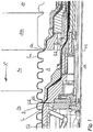
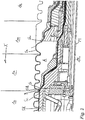
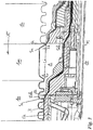
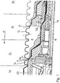
- FIG. 1 to Fig. 7 schematic sectional views of a section of the molding channel in the initial region of the molding line with projecting into the mold channel nozzle device, showing different successive process stages.
- the corrugator in the illustrated embodiment has molding jaws 1n, 1m, which are guided progressively in pairs in a linear forming section 10 in the production direction X in succession.
- the pairs of mold jaws each surround a substantially cylindrical mold cavity with their inwardly facing mold surface.
- the pairs of mold jaws, which are guided axially one after the other in the forming section 10, form a molding channel composed of the cylindrical mold cavities, which extends along the central center axis M indicated in the figures.
- a nozzle device 5 of an extruder protrudes.
- the nozzle device 5 is aligned along the central center axis M.
- the corrugator with its forming jaws 1n, 1m and the nozzle device 5 are each formed symmetrically to the central center axis M.
- only the right side of symmetry is shown, d. H. only the right mold jaws 1n, 1m and only the right side of the symmetrical nozzle device.
- the correspondingly formed and arranged left mold jaws 1n, 1m and the left side of the nozzle device 5 are therefore not shown in the figures.
- the plastic melt hoses are an outer tube Sa and an inner tube Si. These plastic melt hoses pass through the molding channel in the production direction X in the molding section 10. They are molded and cooled on the molding surfaces of the molding jaws 1n, 1m and leave the molding channel as double-walled endless corrugated pipe with socket sections.
- the mold jaws 1n, 1m are driven in the mold channel for progressive movement in the direction of production X via a drive motor, not shown.
- the drive motor can be arranged on the bottom side in the machine table on which the mold jaws 1n, 1m are guided, and mesh with an output pinion with toothed racks formed on the bottom side of the mold jaws.
- the mold jaws 1n, 1m are each returned from the end of the forming section 10 to the beginning of the forming section. This is not shown in the figures.
- the return may be via a motor-driven gripper device, preferably a gripper device for the left mold jaws and a gripper device for the right mold jaws made or by the fact that the left and the right mold jaws are guided in circumferential guideways, preferably via motor-driven drivers.
- a motor-driven gripper device preferably a gripper device for the left mold jaws and a gripper device for the right mold jaws made or by the fact that the left and the right mold jaws are guided in circumferential guideways, preferably via motor-driven drivers.
- normal forming jaws 1n In the mold jaws used in the forming section 10 in the figures, a distinction is to be made between normal forming jaws 1n and socket forming jaws 1m.
- the normal mold jaws 1n have corrugated molding surface for forming the corrugated pipe sections.
- the sleeve mold jaws 1m have a preferably smooth cylindrical or slightly conical sleeve molding surface and serve to form the preferably smooth cylindrical sleeve pipe sections.
- a plurality of pairs of normal mold jaws 1n and only one pair or a few pairs of socket mold jaws 1m are guided in the mold baking cycle and thus in the mold section 10.
- the socket mold jaws can also, if desired, in each case only temporarily introduced into the circuit, ie removed after their introduction back out of the circulation and parked in a parking station on the machine table.
- the nozzle device 5 is designed in the illustrated case such that the plastic melt hoses emerging from the nozzle device are, as mentioned above, formed as two plastic melt tubes, namely as an inner tube Si and an outer tube Sa.
- the nozzle device 5 has an annular outer tube nozzle 5a and an inner tube nozzle 5i on. At the outlet end of the outer hose nozzle 5a, the outer hose Sa exits. At the outlet end of the inner tube nozzle 5i, the inner tube Si exits.
- the outlet end of the outer tube nozzle 5a is the outlet end of the Inner hose 5i - seen in the production direction X - upstream. Thus, it can be said that the inner tube Si is extruded into the outer tube Sa.
- At the inner hose nozzle 5i is a cooling mandrel 5d - seen in the direction of production X - downstream.
- the outer nozzle 5a is associated with an air duct 5ak and the inner nozzle 5i with an air duct 5ik.
- the outlet end of the air channel 5ak is connected downstream of the outlet end of the outer hose nozzle 5a, as seen in the production direction X.
- Air so-called outside air, is blown in through the air channel 5ak as supporting air of the outer tube Sa into the space A, which is formed between the inner wall of the outer tube Sa and the outer wall of the inner tube Si.
- Air, so-called internal air is blown in a corresponding manner via the air duct 5ik as supporting air of the inner tube Si into the space B between the inner wall of the inner tube Si and the outer wall of the cooling mandrel 5d.
- the pressure pa the outside air can be connected via a connected to the air duct 5ak pressure regulator, z. B. depending on the respective positions of the mold jaws used in the mold channel and / or regulated according to a predetermined pressure profile.
- the pressure pi of the internal air can be regulated via a pressure regulator connected to the air duct 5ik.
- the distance between the outlet end of the outer hose nozzle 5a and the outlet end of the inner hose nozzle 5i is greater than the axial extent L of the socket molding surface.
- the nozzle spacing is about 1.4 times as large as the axial extent L of the socket molding surface.
- the sleeve molding surface is formed in each case by only one Muffenformbackencru.
- the molding surface of the socket mold jaw 1m each has a smooth cylindrical or slightly conical molding surface with the axial length Lm, seen in the direction of production X, before and after this sleeve surface then each have a transition region with the axial length Lv and Ln present.
- the transition region has a substantially rectilinear rise in a leading edge at the forward end of the socket forming surface and a substantially rectilinear fall in a trailing edge at the trailing end of the socket forming surface. Between the leading edge and the cylindrical or conical molding surface is a rounded radius region.
- the total axial length L of the socket forming surface is given by the sum of Lv, Lh, Lm (sh. Fig. 3 ).
- the mold surface of the normal mold jaws 1n each have a corrugated mold surface, with axially successively arranged parallel waves with periodically recurring wave crests and troughs, each coaxially arranged around the central center axis M of the mold channel.
- the mold jaws 1n, 1m have, as is known, in the mold surfaces on vacuum openings, which are shown with vacuum channels in the mold jaws via a vacuum device, not shown, to support the installation of the outer tube to the forming surfaces.
- the shaped in the illustrated case in the molding section 10 endless tube receives in the sections in which the normal mold jaws 1n act, the Forming a double-walled corrugated pipe with corrugated outer tube and a smooth cylindrical inner tube, which is welded to the outer tube in each case in the region of the troughs.
- the outer tube and the inner tube are welded together over their entire surface.
- the specified pressure ranges apply to nominal diameters of 100 to 1000.
- the pressure values depend on the wall thickness of the pipes to be produced and on the material to be used.
- the pressure control described and The pressure pa in the space A acts on the inside of the outer tube Sa.
- the space A is bounded by the inside of the exiting from the outer tube 5a outer tube Sa and the production direction through the outside of the exiting from the inner tube 5i Inner tube Si.
- the spray head forms the boundary, namely the spray head section in the area between the outer hose nozzle 5a and the inner hose nozzle 5i.
- the regulation of the pressure pa takes place, as far as the superatmospheric pressure is concerned, by setting a proportional valve. This proportional valve controls the so-called outside air.
- outside air is understood to mean the supporting air which is introduced in space A and acts there on the inside of the outer hose.
- the introduction of this supporting air via the air duct La, which opens between the outer hose nozzle 5a and the inner hose 5i from the spray head in the room A.
- the position of this junction is between the outer hose nozzle 5a and the inner hose nozzle 5i.
- the control of this proportional valve is carried out by the proportional valve is connected to a pressure measuring device which measures the actual value of the output-side pressure of the proportional valve and outputs a measured value signal to an electronic control device.
- the electronic control device the actual pressure value is compared with the desired value of the control program and, with a corresponding deviation, the proportional valve is actuated to compensate for the actual pressure value in space A.
- a switching valve For a venting of the room A, a switching valve is provided. By opening the switching valve, the space A is vented by connection to atmospheric pressure.
- the pressure pa in space A drops to atmospheric pressure in such a case.
- the speed of this pressure drop depends on the Line resistance of the system.
- the line resistance in the system can be formed by corresponding line cross sections so that in the case of switching the changeover valve to the open position, the pressure drop to atmospheric pressure is very fast.
- the control of the changeover valve is dependent on the control program via the electrical control device. As long as the switching valve is open, the atmospheric pressure in the room A remains unchanged, regardless of the setting of the proportional valve. On the outside of the outer tube Sa acts in the illustrated embodiment, a negative pressure.
- the negative pressure is generated by forming slots in the molding surface, which are connected via suction channels in the molding jaws.
- the suction channels communicate with a vacuum pumping device.
- said mold surface of the normal mold jaws 5n and the socket mold jaws 5m is provided with such slits connected to suction channels, so that over said mold surface can be applied with vacuum or partial vacuum.
- such continuous vacuum application between the molding surface and the outside of the outer tube is also concretely provided.
- the pressure in space B is referred to herein as pi.
- the space B is limited by the exiting from the inner tube 5i inner tube Si and the axis of the mold channel through a cooling mandrel, which connects to the spray head in the production direction.
- the regulation of the pressure in the space B can be done by a corresponding apparatus, such as the regulation of the pressure pa.
- the regulation of the pressure pi is also carried out in the illustrated embodiment by a proportional valve, as far as it is super-atmospheric pressure.
- the proportional valve is over one Pressure measuring device which measures the actual value of the output-side pressure of the proportional valve connected, which emits a corresponding measurement signal to an electronic control device. In the electronic control device, this measured actual value of the pressure pi is compared with the desired pressure value of the control program and, in the event of a deviation, the proportional valve is actuated for the corresponding pressure equalization.
- a switching valve which connects the room B with atmospheric pressure in the open position.
- the electronic control of the pressure pa and the electronic control of the pressure pi can be carried out in a common electronic control device.
- the control of the changeover valves via the control program is carried out.
- a sensor device is provided in the mold channel, which detects and detects the beginning of the respective sleeve at the beginning of the mold channel.
- the actual position of the mold jaws is detected in this way; the sensor device is preferably a magnetic or optical sensor device.
- the sensor device is, as described above, thus positioned so that it detects the inlet of the mold jaws in the mold tunnel.
- the corresponding signal of the sensor device is passed to the electronic control device of the pressure control, which preferably has an electronic control program by appropriate programming, in which the desired values of the pressures of the programmed pressure curve depending on the position of the mold jaws are included.
Landscapes
- Engineering & Computer Science (AREA)
- Mechanical Engineering (AREA)
- Manufacturing & Machinery (AREA)
- Extrusion Moulding Of Plastics Or The Like (AREA)
Priority Applications (1)
| Application Number | Priority Date | Filing Date | Title |
|---|---|---|---|
| PL14720154T PL2991815T3 (pl) | 2013-05-03 | 2014-04-30 | Sposób i urządzenie do wytwarzania dwuwarstwowej rury falistej z kielichem rurowym |
Applications Claiming Priority (2)
| Application Number | Priority Date | Filing Date | Title |
|---|---|---|---|
| DE102013007530.0A DE102013007530A1 (de) | 2013-05-03 | 2013-05-03 | Herstellung eines doppellagigen Wellrohres mit Rohrmuffe |
| PCT/EP2014/058823 WO2014177613A1 (de) | 2013-05-03 | 2014-04-30 | Verfahren und vorrichtung zur herstellung eines doppellagigen wellrohres mit rohrmuffe |
Publications (2)
| Publication Number | Publication Date |
|---|---|
| EP2991815A1 EP2991815A1 (de) | 2016-03-09 |
| EP2991815B1 true EP2991815B1 (de) | 2019-08-21 |
Family
ID=50624596
Family Applications (1)
| Application Number | Title | Priority Date | Filing Date |
|---|---|---|---|
| EP14720154.5A Active EP2991815B1 (de) | 2013-05-03 | 2014-04-30 | Verfahren und vorrichtung zur herstellung eines doppellagigen wellrohres mit rohrmuffe |
Country Status (7)
| Country | Link |
|---|---|
| EP (1) | EP2991815B1 (pl) |
| DE (1) | DE102013007530A1 (pl) |
| DK (1) | DK2991815T3 (pl) |
| ES (1) | ES2745712T3 (pl) |
| PL (1) | PL2991815T3 (pl) |
| PT (1) | PT2991815T (pl) |
| WO (1) | WO2014177613A1 (pl) |
Families Citing this family (4)
| Publication number | Priority date | Publication date | Assignee | Title |
|---|---|---|---|---|
| CN104827644B (zh) * | 2015-05-18 | 2017-03-15 | 沈阳新永成塑胶有限公司 | 大截面发泡塑料制品挤出机头 |
| CN108170092B (zh) * | 2018-03-22 | 2024-07-05 | 苏州金纬机械制造有限公司 | 用于波纹管成型机的夹层气和内层气控制系统 |
| CN108274722B (zh) * | 2018-03-26 | 2023-11-21 | 大连三垒科技有限公司 | 波纹管双层承插口在线成型扩口模块尾部压紧装置 |
| CN118925414B (zh) * | 2024-06-30 | 2025-09-12 | 宁夏润阳硅材料科技有限公司 | 一种还原炉废气处理系统及方法 |
Family Cites Families (9)
| Publication number | Priority date | Publication date | Assignee | Title |
|---|---|---|---|---|
| EP0270694B1 (de) | 1986-11-13 | 1990-11-28 | UNICOR GmbH Rahn Plastmaschinen | Vorrichtung zum fortlaufenden Erzeugen von Rohren mit querprofilierter Wandung |
| DE4210482A1 (de) | 1992-03-31 | 1993-10-07 | Wilhelm Hegler | Verfahren und Vorrichtung zur fortlaufenden Herstellung eines Verbundrohres mit Rohr-Muffe |
| FR2718509B1 (fr) * | 1994-04-07 | 1996-08-30 | Courant Ets Sa | Procédé et dispositif pour la réalisation de tulipes sur des tubes annelés à deux parois. |
| DE19724113A1 (de) * | 1997-06-09 | 1998-12-10 | Ralph Peter Dr Hegler | Verbundrohr mit angeformter Rohr-Muffe und Verfahren zu dessen Herstellung |
| DE10110064B4 (de) * | 2001-03-02 | 2005-03-31 | Lupke, Manfred Arno Alfred, Thornhill | Verfahren und Vorrichtung zur Herstellung eines doppelwandigen thermoplastischen Rohres mit einer Rohrmuffe |
| ES2292618T5 (es) | 2001-03-02 | 2014-04-14 | Manfred Arno Alfred Lupke | Procedimiento y dispositivo para fabricar un tubo termoplástico de doble pared con un manguito de acoplamiento |
| DE10335518A1 (de) | 2003-07-31 | 2005-02-24 | Manfred Arno Alfred Thornhill Lupke | Vorrichtung zur Herstellung eines doppelwandigen thermoplastischen Rohrs mit einer Rohrmuffe |
| DE102007050923A1 (de) | 2007-10-23 | 2009-05-07 | Unicor Gmbh | Verfahren und Vorrichtung zur Herstellung eines doppelwandigen thermoplastischen Wellrohres mit einer Rohrmuffe |
| DE202008018223U1 (de) * | 2008-03-18 | 2012-02-13 | Ralph Peter Hegler | Vorrichtung zur fortlaufenden Herstellung einesVerbundrohres mit Rohrmuffe |
-
2013
- 2013-05-03 DE DE102013007530.0A patent/DE102013007530A1/de not_active Ceased
-
2014
- 2014-04-30 DK DK14720154T patent/DK2991815T3/da active
- 2014-04-30 WO PCT/EP2014/058823 patent/WO2014177613A1/de not_active Ceased
- 2014-04-30 EP EP14720154.5A patent/EP2991815B1/de active Active
- 2014-04-30 PL PL14720154T patent/PL2991815T3/pl unknown
- 2014-04-30 ES ES14720154T patent/ES2745712T3/es active Active
- 2014-04-30 PT PT147201545T patent/PT2991815T/pt unknown
Non-Patent Citations (1)
| Title |
|---|
| None * |
Also Published As
| Publication number | Publication date |
|---|---|
| WO2014177613A1 (de) | 2014-11-06 |
| DE102013007530A1 (de) | 2014-11-06 |
| EP2991815A1 (de) | 2016-03-09 |
| ES2745712T3 (es) | 2020-03-03 |
| PL2991815T3 (pl) | 2020-03-31 |
| DK2991815T3 (da) | 2019-11-18 |
| PT2991815T (pt) | 2019-11-27 |
Similar Documents
| Publication | Publication Date | Title |
|---|---|---|
| EP1115550B1 (de) | Vorrichtung zur herstellung von kunststoffrohren | |
| DE4210482A1 (de) | Verfahren und Vorrichtung zur fortlaufenden Herstellung eines Verbundrohres mit Rohr-Muffe | |
| EP0890770A2 (de) | Verbundrohr mit angeformter Rohr-Muffe und Verfahren zu dessen Herstellung | |
| EP0995579A2 (de) | Verfahren zur fortlaufenden Herstellung eines Verbundrohres mit einer Rohr-Muffe und Vorrichtung zur Durchführung des Verfahrens | |
| EP2382075A1 (de) | Verfahren zur herstellung eines wärmeisolierten leitungsrohres | |
| EP2991815B1 (de) | Verfahren und vorrichtung zur herstellung eines doppellagigen wellrohres mit rohrmuffe | |
| EP1363766B1 (de) | Verfahren und vorrichtung zur herstellung eines doppelwandigen thermoplastischen rohres mit einer rohrmuffe | |
| EP2125329B1 (de) | Verfahren und vorrichtung zur fortlaufenden herstellung eines kunststoff-verbundrohres mit rohrmuffe | |
| DE202007016630U1 (de) | Vorrichtung zur fortlaufenden Herstellung eines Verbundrohres mit Rohrmuffe | |
| EP2574444B1 (de) | Verfahren und Vorrichtung zur Herstellung eines doppelwandigen thermoplastischen Wellrohres mit einer Rohrmuffe | |
| DE102006048512B4 (de) | Vorrichtung zur Herstellung von Verbund-Rohren | |
| DE19845321C2 (de) | Vorrichtung zur Herstellung von dünnwandigen glatten Kunststoffrohren mit gewellten Sektionen in unterschiedlichen Abständen zueinander | |
| DE10225582B4 (de) | Verfahren und Vorrichtung zur Herstellung eines doppelwandigen Rohres aus thermoplastischem Kunststoff mit einer Rohrmuffe | |
| EP1985433B1 (de) | Verfahren zur Herstellung von rohrförmigen Kunststoffprofilen | |
| DE4235163A1 (de) | Vorrichtung zum Extrudieren von Kunststoffprofilen | |
| EP0024622B1 (de) | Verfahren und Vorrichtung zur Herstellung eines flachen Hohlkörpers | |
| AT522497B1 (de) | Verfahren zum Herstellen eines Rohres, sowie Vorrichtung zum Durchführen des Verfahrens | |
| DE19947434A1 (de) | Vorrichtung und Verfahren zum Herstellen von Kunststoff-Wellrohren | |
| DE10164897B4 (de) | Verfahren und Vorrichtung zur Herstellung eines doppelwandigen thermoplastischen Rohres mit einer Rohrmuffe | |
| DE9321573U1 (de) | Vorrichtung zur fortlaufenden Herstellung eines Verbundrohres mit Rohr-Muffe | |
| DE102009035040A1 (de) | Verfahren zur fortlaufenden Herstellung eines Rohres und Vorrichtung zur Durchführung des Verfahrens | |
| EP2436504A2 (de) | Verfahren zur fortlaufenden Herstellung eines Verbundrohres mit Rohrmuffe, Verbundrohr mit Rohrmuffe und Vorrichtung zur Durchführung des Verfahrens und zur Herstellung des Verbundrohres | |
| WO2001012413A1 (de) | Vorrichtung und verfahren zum herstellen von kunststoff-wellrohren |
Legal Events
| Date | Code | Title | Description |
|---|---|---|---|
| PUAI | Public reference made under article 153(3) epc to a published international application that has entered the european phase |
Free format text: ORIGINAL CODE: 0009012 |
|
| 17P | Request for examination filed |
Effective date: 20151203 |
|
| AK | Designated contracting states |
Kind code of ref document: A1 Designated state(s): AL AT BE BG CH CY CZ DE DK EE ES FI FR GB GR HR HU IE IS IT LI LT LU LV MC MK MT NL NO PL PT RO RS SE SI SK SM TR |
|
| AX | Request for extension of the european patent |
Extension state: BA ME |
|
| DAX | Request for extension of the european patent (deleted) | ||
| REG | Reference to a national code |
Ref country code: DE Ref legal event code: R079 Ref document number: 502014012458 Country of ref document: DE Free format text: PREVIOUS MAIN CLASS: B29C0047120000 Ipc: B29C0048300000 |
|
| GRAP | Despatch of communication of intention to grant a patent |
Free format text: ORIGINAL CODE: EPIDOSNIGR1 |
|
| STAA | Information on the status of an ep patent application or granted ep patent |
Free format text: STATUS: GRANT OF PATENT IS INTENDED |
|
| RIC1 | Information provided on ipc code assigned before grant |
Ipc: B29C 49/00 20060101ALI20190115BHEP Ipc: B29C 48/92 20190101ALI20190115BHEP Ipc: B29C 48/30 20190101AFI20190115BHEP Ipc: B29C 48/15 20190101ALI20190115BHEP Ipc: B29C 49/78 20060101ALI20190115BHEP |
|
| INTG | Intention to grant announced |
Effective date: 20190214 |
|
| GRAJ | Information related to disapproval of communication of intention to grant by the applicant or resumption of examination proceedings by the epo deleted |
Free format text: ORIGINAL CODE: EPIDOSDIGR1 |
|
| STAA | Information on the status of an ep patent application or granted ep patent |
Free format text: STATUS: REQUEST FOR EXAMINATION WAS MADE |
|
| GRAP | Despatch of communication of intention to grant a patent |
Free format text: ORIGINAL CODE: EPIDOSNIGR1 |
|
| STAA | Information on the status of an ep patent application or granted ep patent |
Free format text: STATUS: GRANT OF PATENT IS INTENDED |
|
| GRAS | Grant fee paid |
Free format text: ORIGINAL CODE: EPIDOSNIGR3 |
|
| GRAA | (expected) grant |
Free format text: ORIGINAL CODE: 0009210 |
|
| STAA | Information on the status of an ep patent application or granted ep patent |
Free format text: STATUS: THE PATENT HAS BEEN GRANTED |
|
| INTC | Intention to grant announced (deleted) | ||
| INTG | Intention to grant announced |
Effective date: 20190705 |
|
| AK | Designated contracting states |
Kind code of ref document: B1 Designated state(s): AL AT BE BG CH CY CZ DE DK EE ES FI FR GB GR HR HU IE IS IT LI LT LU LV MC MK MT NL NO PL PT RO RS SE SI SK SM TR |
|
| REG | Reference to a national code |
Ref country code: GB Ref legal event code: FG4D Free format text: NOT ENGLISH |
|
| REG | Reference to a national code |
Ref country code: CH Ref legal event code: EP |
|
| REG | Reference to a national code |
Ref country code: DE Ref legal event code: R096 Ref document number: 502014012458 Country of ref document: DE |
|
| REG | Reference to a national code |
Ref country code: AT Ref legal event code: REF Ref document number: 1169215 Country of ref document: AT Kind code of ref document: T Effective date: 20190915 |
|
| REG | Reference to a national code |
Ref country code: IE Ref legal event code: FG4D Free format text: LANGUAGE OF EP DOCUMENT: GERMAN |
|
| REG | Reference to a national code |
Ref country code: NL Ref legal event code: FP |
|
| REG | Reference to a national code |
Ref country code: DK Ref legal event code: T3 Effective date: 20191114 |
|
| REG | Reference to a national code |
Ref country code: PT Ref legal event code: SC4A Ref document number: 2991815 Country of ref document: PT Date of ref document: 20191127 Kind code of ref document: T Free format text: AVAILABILITY OF NATIONAL TRANSLATION Effective date: 20191120 |
|
| REG | Reference to a national code |
Ref country code: NO Ref legal event code: T2 Effective date: 20190821 |
|
| REG | Reference to a national code |
Ref country code: SE Ref legal event code: TRGR |
|
| REG | Reference to a national code |
Ref country code: EE Ref legal event code: FG4A Ref document number: E018254 Country of ref document: EE Effective date: 20191009 |
|
| REG | Reference to a national code |
Ref country code: LT Ref legal event code: MG4D |
|
| PG25 | Lapsed in a contracting state [announced via postgrant information from national office to epo] |
Ref country code: BG Free format text: LAPSE BECAUSE OF FAILURE TO SUBMIT A TRANSLATION OF THE DESCRIPTION OR TO PAY THE FEE WITHIN THE PRESCRIBED TIME-LIMIT Effective date: 20191121 Ref country code: HR Free format text: LAPSE BECAUSE OF FAILURE TO SUBMIT A TRANSLATION OF THE DESCRIPTION OR TO PAY THE FEE WITHIN THE PRESCRIBED TIME-LIMIT Effective date: 20190821 Ref country code: LT Free format text: LAPSE BECAUSE OF FAILURE TO SUBMIT A TRANSLATION OF THE DESCRIPTION OR TO PAY THE FEE WITHIN THE PRESCRIBED TIME-LIMIT Effective date: 20190821 |
|
| PG25 | Lapsed in a contracting state [announced via postgrant information from national office to epo] |
Ref country code: AL Free format text: LAPSE BECAUSE OF FAILURE TO SUBMIT A TRANSLATION OF THE DESCRIPTION OR TO PAY THE FEE WITHIN THE PRESCRIBED TIME-LIMIT Effective date: 20190821 Ref country code: RS Free format text: LAPSE BECAUSE OF FAILURE TO SUBMIT A TRANSLATION OF THE DESCRIPTION OR TO PAY THE FEE WITHIN THE PRESCRIBED TIME-LIMIT Effective date: 20190821 Ref country code: IS Free format text: LAPSE BECAUSE OF FAILURE TO SUBMIT A TRANSLATION OF THE DESCRIPTION OR TO PAY THE FEE WITHIN THE PRESCRIBED TIME-LIMIT Effective date: 20191221 |
|
| REG | Reference to a national code |
Ref country code: GR Ref legal event code: EP Ref document number: 20190403421 Country of ref document: GR Effective date: 20200213 |
|
| REG | Reference to a national code |
Ref country code: ES Ref legal event code: FG2A Ref document number: 2745712 Country of ref document: ES Kind code of ref document: T3 Effective date: 20200303 |
|
| PG25 | Lapsed in a contracting state [announced via postgrant information from national office to epo] |
Ref country code: RO Free format text: LAPSE BECAUSE OF FAILURE TO SUBMIT A TRANSLATION OF THE DESCRIPTION OR TO PAY THE FEE WITHIN THE PRESCRIBED TIME-LIMIT Effective date: 20190821 |
|
| PG25 | Lapsed in a contracting state [announced via postgrant information from national office to epo] |
Ref country code: SM Free format text: LAPSE BECAUSE OF FAILURE TO SUBMIT A TRANSLATION OF THE DESCRIPTION OR TO PAY THE FEE WITHIN THE PRESCRIBED TIME-LIMIT Effective date: 20190821 Ref country code: IS Free format text: LAPSE BECAUSE OF FAILURE TO SUBMIT A TRANSLATION OF THE DESCRIPTION OR TO PAY THE FEE WITHIN THE PRESCRIBED TIME-LIMIT Effective date: 20200224 Ref country code: SK Free format text: LAPSE BECAUSE OF FAILURE TO SUBMIT A TRANSLATION OF THE DESCRIPTION OR TO PAY THE FEE WITHIN THE PRESCRIBED TIME-LIMIT Effective date: 20190821 |
|
| REG | Reference to a national code |
Ref country code: DE Ref legal event code: R097 Ref document number: 502014012458 Country of ref document: DE |
|
| PLBE | No opposition filed within time limit |
Free format text: ORIGINAL CODE: 0009261 |
|
| STAA | Information on the status of an ep patent application or granted ep patent |
Free format text: STATUS: NO OPPOSITION FILED WITHIN TIME LIMIT |
|
| PG2D | Information on lapse in contracting state deleted |
Ref country code: IS |
|
| 26N | No opposition filed |
Effective date: 20200603 |
|
| PG25 | Lapsed in a contracting state [announced via postgrant information from national office to epo] |
Ref country code: SI Free format text: LAPSE BECAUSE OF FAILURE TO SUBMIT A TRANSLATION OF THE DESCRIPTION OR TO PAY THE FEE WITHIN THE PRESCRIBED TIME-LIMIT Effective date: 20190821 |
|
| PG25 | Lapsed in a contracting state [announced via postgrant information from national office to epo] |
Ref country code: MC Free format text: LAPSE BECAUSE OF FAILURE TO SUBMIT A TRANSLATION OF THE DESCRIPTION OR TO PAY THE FEE WITHIN THE PRESCRIBED TIME-LIMIT Effective date: 20190821 |
|
| REG | Reference to a national code |
Ref country code: CH Ref legal event code: PL |
|
| PG25 | Lapsed in a contracting state [announced via postgrant information from national office to epo] |
Ref country code: LI Free format text: LAPSE BECAUSE OF NON-PAYMENT OF DUE FEES Effective date: 20200430 Ref country code: CH Free format text: LAPSE BECAUSE OF NON-PAYMENT OF DUE FEES Effective date: 20200430 Ref country code: LU Free format text: LAPSE BECAUSE OF NON-PAYMENT OF DUE FEES Effective date: 20200430 |
|
| REG | Reference to a national code |
Ref country code: BE Ref legal event code: MM Effective date: 20200430 |
|
| PG25 | Lapsed in a contracting state [announced via postgrant information from national office to epo] |
Ref country code: BE Free format text: LAPSE BECAUSE OF NON-PAYMENT OF DUE FEES Effective date: 20200430 |
|
| PG25 | Lapsed in a contracting state [announced via postgrant information from national office to epo] |
Ref country code: MT Free format text: LAPSE BECAUSE OF FAILURE TO SUBMIT A TRANSLATION OF THE DESCRIPTION OR TO PAY THE FEE WITHIN THE PRESCRIBED TIME-LIMIT Effective date: 20190821 Ref country code: CY Free format text: LAPSE BECAUSE OF FAILURE TO SUBMIT A TRANSLATION OF THE DESCRIPTION OR TO PAY THE FEE WITHIN THE PRESCRIBED TIME-LIMIT Effective date: 20190821 |
|
| PG25 | Lapsed in a contracting state [announced via postgrant information from national office to epo] |
Ref country code: MK Free format text: LAPSE BECAUSE OF FAILURE TO SUBMIT A TRANSLATION OF THE DESCRIPTION OR TO PAY THE FEE WITHIN THE PRESCRIBED TIME-LIMIT Effective date: 20190821 |
|
| PGFP | Annual fee paid to national office [announced via postgrant information from national office to epo] |
Ref country code: PL Payment date: 20230220 Year of fee payment: 10 |
|
| PGFP | Annual fee paid to national office [announced via postgrant information from national office to epo] |
Ref country code: NL Payment date: 20230417 Year of fee payment: 10 |
|
| PGFP | Annual fee paid to national office [announced via postgrant information from national office to epo] |
Ref country code: PT Payment date: 20230427 Year of fee payment: 10 Ref country code: NO Payment date: 20230418 Year of fee payment: 10 Ref country code: IE Payment date: 20230425 Year of fee payment: 10 Ref country code: ES Payment date: 20230517 Year of fee payment: 10 Ref country code: EE Payment date: 20230421 Year of fee payment: 10 Ref country code: DK Payment date: 20230419 Year of fee payment: 10 Ref country code: CZ Payment date: 20230417 Year of fee payment: 10 |
|
| PGFP | Annual fee paid to national office [announced via postgrant information from national office to epo] |
Ref country code: TR Payment date: 20230426 Year of fee payment: 10 Ref country code: SE Payment date: 20230419 Year of fee payment: 10 Ref country code: LV Payment date: 20230421 Year of fee payment: 10 Ref country code: GR Payment date: 20230418 Year of fee payment: 10 Ref country code: FI Payment date: 20230417 Year of fee payment: 10 Ref country code: AT Payment date: 20230414 Year of fee payment: 10 |
|
| PGFP | Annual fee paid to national office [announced via postgrant information from national office to epo] |
Ref country code: GB Payment date: 20230420 Year of fee payment: 10 |
|
| REG | Reference to a national code |
Ref country code: EE Ref legal event code: MM4A Ref document number: E018254 Country of ref document: EE Effective date: 20240430 |
|
| REG | Reference to a national code |
Ref country code: DK Ref legal event code: EBP Effective date: 20240430 |
|
| REG | Reference to a national code |
Ref country code: NL Ref legal event code: MM Effective date: 20240501 |
|
| PG25 | Lapsed in a contracting state [announced via postgrant information from national office to epo] |
Ref country code: PT Free format text: LAPSE BECAUSE OF NON-PAYMENT OF DUE FEES Effective date: 20241031 |
|
| REG | Reference to a national code |
Ref country code: AT Ref legal event code: MM01 Ref document number: 1169215 Country of ref document: AT Kind code of ref document: T Effective date: 20240430 |
|
| GBPC | Gb: european patent ceased through non-payment of renewal fee |
Effective date: 20240430 |
|
| PG25 | Lapsed in a contracting state [announced via postgrant information from national office to epo] |
Ref country code: PT Free format text: LAPSE BECAUSE OF NON-PAYMENT OF DUE FEES Effective date: 20241031 |
|
| REG | Reference to a national code |
Ref country code: SE Ref legal event code: EUG |
|
| PG25 | Lapsed in a contracting state [announced via postgrant information from national office to epo] |
Ref country code: NO Free format text: LAPSE BECAUSE OF NON-PAYMENT OF DUE FEES Effective date: 20240430 |
|
| PG25 | Lapsed in a contracting state [announced via postgrant information from national office to epo] |
Ref country code: GR Free format text: LAPSE BECAUSE OF NON-PAYMENT OF DUE FEES Effective date: 20241104 Ref country code: FI Free format text: LAPSE BECAUSE OF NON-PAYMENT OF DUE FEES Effective date: 20240430 Ref country code: NL Free format text: LAPSE BECAUSE OF NON-PAYMENT OF DUE FEES Effective date: 20240501 |
|
| PG25 | Lapsed in a contracting state [announced via postgrant information from national office to epo] |
Ref country code: GB Free format text: LAPSE BECAUSE OF NON-PAYMENT OF DUE FEES Effective date: 20240430 |
|
| PG25 | Lapsed in a contracting state [announced via postgrant information from national office to epo] |
Ref country code: EE Free format text: LAPSE BECAUSE OF NON-PAYMENT OF DUE FEES Effective date: 20240430 Ref country code: LV Free format text: LAPSE BECAUSE OF NON-PAYMENT OF DUE FEES Effective date: 20240430 |
|
| PG25 | Lapsed in a contracting state [announced via postgrant information from national office to epo] |
Ref country code: AT Free format text: LAPSE BECAUSE OF NON-PAYMENT OF DUE FEES Effective date: 20240430 |
|
| PG25 | Lapsed in a contracting state [announced via postgrant information from national office to epo] |
Ref country code: CZ Free format text: LAPSE BECAUSE OF NON-PAYMENT OF DUE FEES Effective date: 20240430 |
|
| PG25 | Lapsed in a contracting state [announced via postgrant information from national office to epo] |
Ref country code: NO Free format text: LAPSE BECAUSE OF NON-PAYMENT OF DUE FEES Effective date: 20240430 Ref country code: NL Free format text: LAPSE BECAUSE OF NON-PAYMENT OF DUE FEES Effective date: 20240501 Ref country code: LV Free format text: LAPSE BECAUSE OF NON-PAYMENT OF DUE FEES Effective date: 20240430 Ref country code: GR Free format text: LAPSE BECAUSE OF NON-PAYMENT OF DUE FEES Effective date: 20241104 Ref country code: GB Free format text: LAPSE BECAUSE OF NON-PAYMENT OF DUE FEES Effective date: 20240430 Ref country code: FI Free format text: LAPSE BECAUSE OF NON-PAYMENT OF DUE FEES Effective date: 20240430 Ref country code: EE Free format text: LAPSE BECAUSE OF NON-PAYMENT OF DUE FEES Effective date: 20240430 Ref country code: CZ Free format text: LAPSE BECAUSE OF NON-PAYMENT OF DUE FEES Effective date: 20240430 Ref country code: AT Free format text: LAPSE BECAUSE OF NON-PAYMENT OF DUE FEES Effective date: 20240430 |
|
| PG25 | Lapsed in a contracting state [announced via postgrant information from national office to epo] |
Ref country code: DK Free format text: LAPSE BECAUSE OF NON-PAYMENT OF DUE FEES Effective date: 20240430 |
|
| PG25 | Lapsed in a contracting state [announced via postgrant information from national office to epo] |
Ref country code: IE Free format text: LAPSE BECAUSE OF NON-PAYMENT OF DUE FEES Effective date: 20240430 |
|
| REG | Reference to a national code |
Ref country code: ES Ref legal event code: FD2A Effective date: 20250604 |
|
| PG25 | Lapsed in a contracting state [announced via postgrant information from national office to epo] |
Ref country code: PL Free format text: LAPSE BECAUSE OF NON-PAYMENT OF DUE FEES Effective date: 20240430 |
|
| PGFP | Annual fee paid to national office [announced via postgrant information from national office to epo] |
Ref country code: DE Payment date: 20250327 Year of fee payment: 12 |
|
| PG25 | Lapsed in a contracting state [announced via postgrant information from national office to epo] |
Ref country code: ES Free format text: LAPSE BECAUSE OF NON-PAYMENT OF DUE FEES Effective date: 20240501 |
|
| PGFP | Annual fee paid to national office [announced via postgrant information from national office to epo] |
Ref country code: IT Payment date: 20250430 Year of fee payment: 12 |
|
| PGFP | Annual fee paid to national office [announced via postgrant information from national office to epo] |
Ref country code: FR Payment date: 20250422 Year of fee payment: 12 |
|
| PG25 | Lapsed in a contracting state [announced via postgrant information from national office to epo] |
Ref country code: SE Free format text: LAPSE BECAUSE OF NON-PAYMENT OF DUE FEES Effective date: 20240501 |