EP2991220A2 - Magnet management in electric machines - Google Patents
Magnet management in electric machines Download PDFInfo
- Publication number
- EP2991220A2 EP2991220A2 EP15182787.0A EP15182787A EP2991220A2 EP 2991220 A2 EP2991220 A2 EP 2991220A2 EP 15182787 A EP15182787 A EP 15182787A EP 2991220 A2 EP2991220 A2 EP 2991220A2
- Authority
- EP
- European Patent Office
- Prior art keywords
- temperature
- ferrite
- permanent magnets
- electrical machine
- type permanent
- Prior art date
- Legal status (The legal status is an assumption and is not a legal conclusion. Google has not performed a legal analysis and makes no representation as to the accuracy of the status listed.)
- Granted
Links
Images

Classifications
-
- H—ELECTRICITY
- H02—GENERATION; CONVERSION OR DISTRIBUTION OF ELECTRIC POWER
- H02P—CONTROL OR REGULATION OF ELECTRIC MOTORS, ELECTRIC GENERATORS OR DYNAMO-ELECTRIC CONVERTERS; CONTROLLING TRANSFORMERS, REACTORS OR CHOKE COILS
- H02P29/00—Arrangements for regulating or controlling electric motors, appropriate for both AC and DC motors
- H02P29/60—Controlling or determining the temperature of the motor or of the drive
- H02P29/62—Controlling or determining the temperature of the motor or of the drive for raising the temperature of the motor
-
- H—ELECTRICITY
- H02—GENERATION; CONVERSION OR DISTRIBUTION OF ELECTRIC POWER
- H02P—CONTROL OR REGULATION OF ELECTRIC MOTORS, ELECTRIC GENERATORS OR DYNAMO-ELECTRIC CONVERTERS; CONTROLLING TRANSFORMERS, REACTORS OR CHOKE COILS
- H02P29/00—Arrangements for regulating or controlling electric motors, appropriate for both AC and DC motors
- H02P29/60—Controlling or determining the temperature of the motor or of the drive
- H02P29/66—Controlling or determining the temperature of the rotor
- H02P29/662—Controlling or determining the temperature of the rotor the rotor having permanent magnets
-
- H—ELECTRICITY
- H02—GENERATION; CONVERSION OR DISTRIBUTION OF ELECTRIC POWER
- H02P—CONTROL OR REGULATION OF ELECTRIC MOTORS, ELECTRIC GENERATORS OR DYNAMO-ELECTRIC CONVERTERS; CONTROLLING TRANSFORMERS, REACTORS OR CHOKE COILS
- H02P2207/00—Indexing scheme relating to controlling arrangements characterised by the type of motor
- H02P2207/05—Synchronous machines, e.g. with permanent magnets or DC excitation
Definitions
- Embodiments of the invention relate generally to electrical machines and the heating of magnets in ferrite-type magnet motors to prevent demagnetization and, more particularly, to magnet management of these heating methodologies and/or motors that may be used in electric and/or hybrid electric vehicles, as well as other applications.
- PM permanent magnet
- Stator permanent magnet machines are electrical machines that are designed such that the PMs in the machine are positioned on the stator.
- Stator permanent magnet machines can thus refer to, but are not limited to, permanent magnet flux switching machines, permanent magnet flux reversal machines, and doubly-salient permanent magnet machines.
- IPM machines are electrical machines that are designed such that the PMs in the machine are embedded inside the laminations of a rotor. IPM machines can thus refer to IPM motors or generators widely used in a variety of applications, including aircraft, automobiles and industrial usage.
- demagnetization of the PMs can occur if the electrical machine is exposed to extremely high or extremely low temperatures. For example, if the PMs are rare earth magnets, exposure of the PMs to extremely high temperatures can make the PMs more susceptible to demagnetization. Conversely, if the PMs are ferrite magnets, exposure of the PMs to low temperatures (e.g., -40° to 60° C) can make the PMs more susceptible to demagnetization.
- ferrite magnets in PM electrical machines can provide cost savings as compared to the use of rare earth magnets, and thus the use of ferrite magnets may be desirable in some PM electrical machines. While ferrite magnets are more prone to demagnetization at lower temperatures compared to rare earth magnets, they are less prone to demagnetization at higher temperatures than rare earth magnets. Thus, if solutions can be provided for preventing demagnetization of ferrite magnets at low temperatures, ferrite magnet PM machines can be a desirable alternative to rare earth magnet PM machines.
- the aforementioned referenced patent application provides for various systems and methods for preventing the demagnetization of ferrite magnets in a PM machine.
- the improved PM machine may then lead to enhanced opportunities for a wide range of applications including, for example, with vehicle applications.
- the present invention overcomes at least some of the aforementioned drawbacks by providing a method of controlling a ferrite-type permanent magnet electrical machine that mitigates the degradation of machine performance due to demagnetization of the magnets at low temperatures. More specifically, the present invention is directed to a control module, or controller, that provides for magnet management instructions in various applications such as, but not limited, in electric or hybrid electric vehicles.
- a method of controlling a ferrite-type permanent magnet electrical machine comprising: one of receiving and estimating a temperature of a plurality of permanent magnets; determining if the temperature is below a predetermined temperature; and if the temperature is below the predetermined temperature, at least one of: selectively heating the plurality of ferrite-type permanent magnets in order to prevent demagnetization of the plurality of permanent magnets; and derating the electrical machine.
- a controller comprising programming instructions to: one of receive and estimate a temperature of a plurality of ferrite-type permanent magnets in an electrical machine; compare the temperature with a predetermined temperature; and send current injection information to an operating controller of the electrical machine, wherein the current injection information comprises instructions configured to prevent demagnetization of the plurality of ferrite-type permanent magnets.
- a controller comprising programming instructions to: receive or estimate a back-emf of a ferrite-type permanent magnet machine, said ferrite-type permanent magnet machine having a plurality of ferrite-type permanent magnets; compare the received or estimated back-emf with a predetermined back-emf; and send current injection information to an operating controller of the ferrite-type permanent machine, wherein the current injection information comprises instructions configured to prevent demagnetization of the plurality of ferrite-type permanent magnets.
- a method of controlling a ferrite-type permanent magnet electrical machine comprising: one of receiving and estimating a magnetization level of a plurality of permanent magnets; determining if the magnetization level is above a predetermined level; and if the magnetization level is above the predetermined level, at least one of: selectively heating the plurality of ferrite-type permanent magnets in order to prevent demagnetization of the plurality of permanent magnets; and derating the electrical machine.
- a controller comprising programming instructions to: inject one of a current or a voltage to a ferrite-type permanent magnet machine, said ferrite-type permanent magnet machine having a plurality of ferrite-type permanent magnets; estimate impedance based on the injecting; selectively heat the plurality of ferrite-type permanent magnets based on the estimated impedance; and limit current to the machine.
- ranges are inclusive and independently combinable (e.g., ranges of "up to about 25 wt. %,” is inclusive of the endpoints and all intermediate values of the ranges of "about 5 wt. % to about 25 wt. %,” etc.).
- the modified "about” used in connection with a quantity is inclusive of the stated value and has the meaning dictated by the context (e.g., includes the degree of error associated with measurement of the particular quantity). Accordingly, the value modified by the term “about” is not necessarily limited only to the precise value specified.
- ferrite-type magnet means both ferrite-based magnets as well as types of magnets and/or magnet compositions' now known or later developed' that exhibit temperature-related behaviors similar to the ferrite-based magnets discussed herein.
- certain embodiments of ferrite-type magnets could conceivably include magnets and/or magnet compositions that, in fact, contact no, or only trace amounts, of iron.
- low temperature means at or below temperatures that can make ferrite-type permanent magnets more susceptible to demagnetization. For example, but not by limitation, it could be in the range from about -40° C to about 60° C. However, the low temperature may be different than the aforementioned range. For example, the range could differ for a variety of reasons including the motor size and configuration; pressure; motor application; and/or other factors.
- the present invention is related and extends from aspects of commonly assigned US Patent Application Serial Number 14/064,547 , entitled “SYSTEM AND METHOD FOR HEATING FERRITE MAGNET MOTORS FOR LOW TEMPERATURES", the contents which are incorporated herein by reference in its entirety.
- this invention provides for further application of the methods and systems of the earlier invention. These applications include, but are not limited to, the operation of vehicles that may have one or more motors that have ferrite-type magnets therein.
- MMM Magnet Management Module
- controller that is configured to aid in the prevention of demagnetization of ferrite-type magnets at or during lower temperatures.
- the MMM may reside in a motor control module.
- the MMM introduces the concept of rotor or stator heating to ensure that the ferrite-type magnet temperature is above the demagnetizing temperature.
- the MMM has the magnet temperature as a controllable variable to ensure the magnets are not demagnetized.
- Demagnetization of the magnets can affect the operating flux density and field strength of the magnets of the ferrite-type magnet. Demagnetization can ultimately result in degraded motor performance and/or a destroyed motor.
- the MMM may observe the remanence and coercivity from at least one of the flux linkage and output torque of the motor.
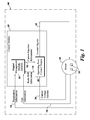
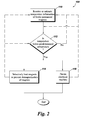
- FIGS. 1-3 the figures illustrate a schematic diagram of a magnet management environment ( FIG. 1 ) and two flowcharts ( FIGS. 2 and 3 ) of methods of operation, respectively, according to aspects of the present invention.
- a magnet management module (MMM) 10 resides within a control module 20 that is used to operate a motor, or electrical machine, 50 that includes a plurality of ferrite-type magnets 52 therein.
- the environment may reside further within a vehicle 60.
- the MMM 10 receives instructions and/or information and sends instructions and/or information ultimately preventing the demagnetization of the magnets 52 due to low temperatures.
- the MMM 10 may receive information including one of: temperature information 12 and/or flux, or magnetization, information 18 from the motor 50 and back-emf information 14 from an operating point control module 30 that is in communication with the motor 50.
- the operating point control module 30 may be receiving at least one of current, voltage, and/or position information 34 and sending inverter signals 32 to the motor 50.
- the inverter signals 32 sent to the motor 50 may be based, in part, on current injection information 16.
- the MMM 10 comprises a control module or controller that comprises programming instructions.
- the programming instructions comprise instructions to receive the temperature information 12 of the plurality of ferrite-type permanent magnets 52 residing in the electrical machine 50.
- the MMM 10 may estimate a temperature of the plurality of ferrite-type permanent magnets 52.
- the MMM 10 also may compare the received and/or estimated temperature to one, or more, predetermined temperatures. Based on the comparison, the MMM 10 sends current injection information 16 to the operating point control module 30 of the electrical machine 50 so as to prevent demagnetization of the magnets 52.
- the back-emf information 14 from the operating point control module 30 may be derived from one of the current, voltage, and position 34 of the machine 50.
- the MMM 10 sends current injection information 16 to the operating point control module 30 that, in turn, leads to inverter signals 32 sent to the motor 50 so as to prevent demagnetization of the magnets 52 therein.
- the current injection information 16 includes instructions to selectively heat the plurality of ferrite-type permanent magnets 52 by at least one of: heating the magnets 52 for a fixed duration; heating the magnets 52 to a predetermined temperature; and, heating the magnets 52 to a predetermined rate of rise in temperature of the magnets 52.
- the current injection information 16 further comprises instructions to also derate operation of the motor 50 and/or delay operation of the motor 50.
- One way to derate and/or delay operation is to limit the current to the motor 50 and, in the case of delaying operation, reduce the current to zero to the motor 50.
- the delay in the operation of the motor 50 could be one or more of the following: simply inactivating operation of the motor 50; delaying operation of the motor 50 for a set period of time; delaying operation of the motor 50 until a predetermined temperature in the magnets 52 is reached; and/or delaying operation of the motor 50 until a predetermined rate of rise in the temperature increase is reached.
- the method 100 may comprise receiving and/or estimating a temperature of the plurality of ferrite-type permanent magnets at 110.
- the MMM 10 ( FIG. 1 ) then, at 112, determines if the received and/or estimated temperature is below a predetermined temperature. If at 112, the answer is "NO" (i.e., the received and/or estimated temperature is not below the predetermined temperature), then the method could stop; or, alternatively, the MMM 10 may continue receiving and/or estimating temperatures of the magnets 52 (i.e., resume back to 110).
- the method 100 proceeds to one or both of 114 and 116.
- the method 100 continues with the MMM 10 selectively heating the magnets 52 so as to prevent demagnetization of the magnets 52.
- the method 100 continues with the MMM 10 derating the motor 50.
- the method 100 may end.
- the method 100 may optionally return either of continuing to receive and/or estimate temperatures of the magnets 52 (i.e., 110) and/or determining if the received and/or estimated temperature is below the predetermined temperature, at 112.
- the selective heating may further comprise one or more types of selective heating including heating for a predetermined period of time; heating until the magnets 52 reach a certain, predetermined setpoint temperature; and/or, heating until a predetermined rate of rise temperature rate is attained.
- the determining may further comprise determining if a time delay is available prior to operation of the machine 50 in a situation where 112 answers "YES".
- the time delay may include a determination if the vehicle 60 user can, or cannot, accept immediate use of the motor 50 and vehicle 60. If a time delay is not available, then the motor 50 may be derated (i.e., 116) or the motor 50 may be made inoperable, until the predetermined temperature is reached so as to not demagnetize the magnets 52. Contrastingly, if a time delay is available, then the selective heating, at 114, can take place. The derating at 116 may be accomplished by limiting the current available to the motor 50.
- the estimating of the temperature of the plurality of the permanent magnets 52 can include estimating by indirectly measuring the temperature of the magnets 52. That is temperatures information of element(s) other than measuring the actual temperature of the magnets 52 proper may be obtained. From this indirect measurement, then the temperature of the magnets 52 may be estimated and/or derived. For example, the temperature of one or more of the lamination temperature, ambient temperature, housing temperature, and winding temperature may be measured. Additional information may optionally be used in addition to the indirect temperatures to derive an estimate of the magnet temperature. For example, a thermal model of the electrical machine 50 and/or information related to the heat in the machine 50 may be applied to the indirect temperature information of the machine 50 to then estimate the temperature of the magnets 52.
- the estimating of the temperature of the plurality of the permanent magnets 52 can additionally or alternatively include estimating based on one or more of the motor terminal quantities of the machine 50.
- the motor terminal quantities may include, for example, voltage and/or current.
- the machine 50 may be run with zero current as an open circuit spinning and short circuit testing.
- the estimating of the temperature of the plurality of the permanent magnets 52 can additionally or alternatively include estimating the temperature using injected test voltage and/or test current to the machine 50 and then estimating the small signal impedance and/or estimating the magnetization level.
- step(s) it should be apparent that in embodiments of the method, that various repeating of step(s) is possible without diverting from the invention.
- the receiving, estimating, determining, and heating could each, or all, could be continually repeating, intermittently repeating, discretely occurring, automatically occurring, or operational by the user of the vehicle 60 and/or motor 50.
- the method 200 may comprise receiving and/or estimating a magnetization level, or flux level, of the plurality of ferrite-type permanent magnets at 210.
- the MMM 10 ( FIG. 1 ) then, at 212, determines if the received or estimated flux level is above a predetermined level. If at 212, the answer is "NO" (i.e., the received and/or estimated flux level is not above the predetermined level), then the method could stop; or, alternatively, the MMM 10 may continue receiving and/or estimating flux levels of the magnets 52 (i.e., resume back to 210).
- the method 200 proceeds to one or both of 214 and 216.
- the method 200 continues with the MMM 10 selectively heating the magnets 52 so as to prevent demagnetization of the magnets 52.
- the method 200 continues with the MMM 10 derating the motor 50.
- the method 200 may end.
- the method 200 may optionally return either of continuing to receive and/or estimate flux levels of the magnets 52 (i.e., 210) and/or determining if the received and/or estimated flux level is above the predetermined level, at 212.
- the selective heating may further comprise one or more types of selective heating including heating for a predetermined period of time; heating until the magnets 52 reach a certain, predetermined setpoint temperature; and/or, heating until a predetermined rate of rise temperature rate is attained.
- the determining may further comprise determining if a time delay is available prior to operation of the machine 50 in a situation where 212 answers "YES".
- the time delay may include a determination if the vehicle 60 user can, or cannot, accept immediate use of the motor 50 and vehicle 60. If a time delay is not available, then the motor 50 may be derated (i.e., 216) or the motor 50 may be made inoperable, until the predetermined temperature is reached so as to not demagnetize the magnets 52. Contrastingly, if a time delay is available, then the selective heating, at 214, can take place. The derating at 216 may be accomplished by limiting the current available to the motor 50.
- the estimating of the flux level of the plurality of the permanent magnets 52 can include estimating flux level based on one or more of the motor terminal quantities of the machine 50.
- the motor terminal quantities may include, for example, voltage and/or current.
- the machine 50 may be run with zero current as an open circuit spinning and short circuit testing.
- the estimating of the flux level of the plurality of the permanent magnets 52 can additionally or alternatively include estimating the flux level using injected test voltage and/or test current to the machine 50 and then estimating the small signal impedance and/or estimating the flux level.
- step(s) it should be apparent that in embodiments of the method, that various repeating of step(s) is possible without diverting from the invention.
- the receiving, estimating, determining, and heating could each, or all, could be continually repeating, intermittently repeating, discretely occurring, automatically occurring, or operational by the user of the vehicle 60 and/or motor 50.
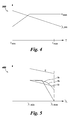
- FIG. 4 depicting the variation of current limits imposed on the machine the permanent magnet flux linkage, or magnetization level, against temperature
- FIG. 5 depicting impedance and current limits imposed on the machine against flux linkage in the machine, respectively.
- the current limit of a machine is shown as I max .
- the current limit of the machine is derated (i.e., sloping graph).
- the permanent magnet flux linkage, or magnetization level is shown as ⁇ pm .
- the y-axis shows the received or estimated magnet temperature, as T.
- the current limits of the machine are a function of the magnetization level. Embodiments of only three possible current limits are shown at I a , I b , and I c .
- the current limit may be virtually any function of the magnetization level. For example, at I c the function may be linear; at I b the function may be curved downward; and, at I a the function may be level and then linear below a certain value.
- a small signal impedance (voltage or current) may be injected. From the injection, the impedance may be estimated.
- an electrical machine such as a traction motor in an electric vehicle or hybrid electric vehicle aspects of the present invention can be used in other electric machine applications without departing from the scope of the invention.
- the electric machine could be a stationary motor used in a cold temperature environment, a non-traction motor on a vehicle, and the like.
- a method of controlling a ferrite-type permanent magnet electrical machine comprising: one of receiving and estimating a temperature of a plurality of permanent magnets; determining if the temperature is below a predetermined temperature; and if the temperature is below the predetermined temperature, at least one of: selectively heating the plurality of ferrite-type permanent magnets in order to prevent demagnetization of the plurality of permanent magnets; and derating the electrical machine.
- a controller comprising programming instructions to: one of receive and estimate a temperature of a plurality of ferrite-type permanent magnets in an electrical machine; compare the temperature with a predetermined temperature; and send current injection information to an operating controller of the electrical machine, wherein the current injection information comprises instructions configured to prevent demagnetization of the plurality of ferrite-type permanent magnets.
- a controller comprising programming instructions to: receive or estimate a back-emf of a ferrite-type permanent magnet machine, said ferrite-type permanent magnet machine having a plurality of ferrite-type permanent magnets; compare the received or estimated back-emf with a predetermined back-emf; and send current injection information to an operating controller of the ferrite-type permanent machine, wherein the current injection information comprises instructions configured to prevent demagnetization of the plurality of ferrite-type permanent magnets.
- a method of controlling a ferrite-type permanent magnet electrical machine comprising: one of receiving and estimating a magnetization level of a plurality of permanent magnets; determining if the magnetization level is above a predetermined level; and if the magnetization level is above the predetermined level, at least one of: selectively heating the plurality of ferrite-type permanent magnets in order to prevent demagnetization of the plurality of permanent magnets; and derating the electrical machine.
- a controller comprising programming instructions to: inject one of a current or a voltage to a ferrite-type permanent magnet machine, said ferrite-type permanent magnet machine having a plurality of ferrite-type permanent magnets; estimate impedance based on the injecting; selectively heat the plurality of ferrite-type permanent magnets based on the estimated impedance; and limit current to the machine.
Landscapes
- Engineering & Computer Science (AREA)
- Power Engineering (AREA)
- Control Of Electric Motors In General (AREA)
- Manufacturing & Machinery (AREA)
- Chemical & Material Sciences (AREA)
- Dispersion Chemistry (AREA)
- Control Of Ac Motors In General (AREA)
- Control Of Motors That Do Not Use Commutators (AREA)
- Electric Propulsion And Braking For Vehicles (AREA)
- Measuring Magnetic Variables (AREA)
Abstract
Description
- Embodiments of the invention relate generally to electrical machines and the heating of magnets in ferrite-type magnet motors to prevent demagnetization and, more particularly, to magnet management of these heating methodologies and/or motors that may be used in electric and/or hybrid electric vehicles, as well as other applications.
- The usage of electrical machines in various industries has continued to become more prevalent in numerous industrial, commercial, and transportation industries over time. In an attempt to realize high performance in electric machines, the choice of using permanent magnet (PM) materials is becoming more popular for many applications. In such machines, the PMs can either replace electromagnets in traditional designs, or novel topologies can be developed to make the best use of the properties and characteristics of PMs.
- One PM electrical machine topology that has been developed is referred to as "stator permanent magnet machines," which are electrical machines that are designed such that the PMs in the machine are positioned on the stator. Stator permanent magnet machines can thus refer to, but are not limited to, permanent magnet flux switching machines, permanent magnet flux reversal machines, and doubly-salient permanent magnet machines. Another PM electrical machine topology that has been developed is referred to as "interior permanent magnet (IPM) machines," which are electrical machines that are designed such that the PMs in the machine are embedded inside the laminations of a rotor. IPM machines can thus refer to IPM motors or generators widely used in a variety of applications, including aircraft, automobiles and industrial usage.
- One issue that is taken into consideration when constructing and operating a PM electrical machine is demagnetization of the PMs. Depending on the type of PMs employed, demagnetization of the PMs can occur if the electrical machine is exposed to extremely high or extremely low temperatures. For example, if the PMs are rare earth magnets, exposure of the PMs to extremely high temperatures can make the PMs more susceptible to demagnetization. Conversely, if the PMs are ferrite magnets, exposure of the PMs to low temperatures (e.g., -40° to 60° C) can make the PMs more susceptible to demagnetization.
- It is recognized that the use of ferrite magnets in PM electrical machines can provide cost savings as compared to the use of rare earth magnets, and thus the use of ferrite magnets may be desirable in some PM electrical machines. While ferrite magnets are more prone to demagnetization at lower temperatures compared to rare earth magnets, they are less prone to demagnetization at higher temperatures than rare earth magnets. Thus, if solutions can be provided for preventing demagnetization of ferrite magnets at low temperatures, ferrite magnet PM machines can be a desirable alternative to rare earth magnet PM machines.
- As a result, the aforementioned referenced patent application provides for various systems and methods for preventing the demagnetization of ferrite magnets in a PM machine. This leads to a ferrite magnet PM machine that is useable over a wider range of ambient temperatures and that exhibits improved resistance to corrosion and improved stability. The improved PM machine may then lead to enhanced opportunities for a wide range of applications including, for example, with vehicle applications.
- Accordingly, there is an opportunity to improve upon the operation, for example, of vehicles (and in other applications) that include motors that utilize these ferrite-type magnet methods and systems in their PM machine(s).
- The present invention overcomes at least some of the aforementioned drawbacks by providing a method of controlling a ferrite-type permanent magnet electrical machine that mitigates the degradation of machine performance due to demagnetization of the magnets at low temperatures. More specifically, the present invention is directed to a control module, or controller, that provides for magnet management instructions in various applications such as, but not limited, in electric or hybrid electric vehicles.
- Therefore, in accordance with one aspect of the invention, a method of controlling a ferrite-type permanent magnet electrical machine, the method comprising: one of receiving and estimating a temperature of a plurality of permanent magnets; determining if the temperature is below a predetermined temperature; and if the temperature is below the predetermined temperature, at least one of: selectively heating the plurality of ferrite-type permanent magnets in order to prevent demagnetization of the plurality of permanent magnets; and derating the electrical machine.
- In accordance with another aspect of the invention, a controller comprising programming instructions to: one of receive and estimate a temperature of a plurality of ferrite-type permanent magnets in an electrical machine; compare the temperature with a predetermined temperature; and send current injection information to an operating controller of the electrical machine, wherein the current injection information comprises instructions configured to prevent demagnetization of the plurality of ferrite-type permanent magnets.
- In accordance with another aspect of the invention, a controller comprising programming instructions to: receive or estimate a back-emf of a ferrite-type permanent magnet machine, said ferrite-type permanent magnet machine having a plurality of ferrite-type permanent magnets; compare the received or estimated back-emf with a predetermined back-emf; and send current injection information to an operating controller of the ferrite-type permanent machine, wherein the current injection information comprises instructions configured to prevent demagnetization of the plurality of ferrite-type permanent magnets.
- In accordance with another aspect of the invention, a method of controlling a ferrite-type permanent magnet electrical machine, the method comprising: one of receiving and estimating a magnetization level of a plurality of permanent magnets; determining if the magnetization level is above a predetermined level; and if the magnetization level is above the predetermined level, at least one of: selectively heating the plurality of ferrite-type permanent magnets in order to prevent demagnetization of the plurality of permanent magnets; and derating the electrical machine.
- In accordance with another aspect of the invention, a controller comprising programming instructions to: inject one of a current or a voltage to a ferrite-type permanent magnet machine, said ferrite-type permanent magnet machine having a plurality of ferrite-type permanent magnets; estimate impedance based on the injecting; selectively heat the plurality of ferrite-type permanent magnets based on the estimated impedance; and limit current to the machine.
- Various other features and advantages of the present invention will be made apparent from the following detailed description and the drawings.
- These and other features, aspects, and advantages of the present invention will become better understood when the following detailed description is read with reference to the accompanying drawings in which like characters represent like parts throughout the drawings, wherein:
-
Fig. 1 is a schematic diagram of a magnet management environment according to an embodiment of the present invention. -
Fig. 2 is a flowchart of a method of operation according to an embodiment of the present invention. -
Fig. 3 is a flowchart of a method of operation according to an embodiment of the present invention. -
Fig. 4 is a graph depicting the variation of current limit imposed on the machine and the permanent magnet flux linkage, or magnetization level, against received or estimated temperature according to an embodiment of the present invention. -
Fig. 5 is a graph depicting impedance against flux linkage, or magnetization level, in the machine, and the variations of current limits against the flux linkage in the machine, according to an embodiment of the present invention. - Unless defined otherwise, technical and scientific terms used herein have the same meaning as is commonly understood by one of ordinary skill in the art with respect to the presently disclosed subject matter. The terms "first", "second", and the like, as used herein do not denote any order, quantity, or importance, but rather are used to distinguish one element from another. The terms "a", "an", and "the" do not denote a limitation of quantity, but rather denote the presence of at least one of the referenced item, and the terms "front", "back", "bottom", and/or "top", unless otherwise noted, are used for convenience of description only, and are not limited to any one position or spatial orientation.
- If ranges are disclosed, the endpoints of all ranges directed to the same component or property are inclusive and independently combinable (e.g., ranges of "up to about 25 wt. %," is inclusive of the endpoints and all intermediate values of the ranges of "about 5 wt. % to about 25 wt. %," etc.). The modified "about" used in connection with a quantity is inclusive of the stated value and has the meaning dictated by the context (e.g., includes the degree of error associated with measurement of the particular quantity). Accordingly, the value modified by the term "about" is not necessarily limited only to the precise value specified.
- As used herein, "ferrite-type magnet" means both ferrite-based magnets as well as types of magnets and/or magnet compositions' now known or later developed' that exhibit temperature-related behaviors similar to the ferrite-based magnets discussed herein. For example, but not by limitation, certain embodiments of ferrite-type magnets could conceivably include magnets and/or magnet compositions that, in fact, contact no, or only trace amounts, of iron.
- As used herein, "low temperature" means at or below temperatures that can make ferrite-type permanent magnets more susceptible to demagnetization. For example, but not by limitation, it could be in the range from about -40° C to about 60° C. However, the low temperature may be different than the aforementioned range. For example, the range could differ for a variety of reasons including the motor size and configuration; pressure; motor application; and/or other factors.
- As referenced above, the present invention is related and extends from aspects of commonly assigned
US Patent , entitled "SYSTEM AND METHOD FOR HEATING FERRITE MAGNET MOTORS FOR LOW TEMPERATURES", the contents which are incorporated herein by reference in its entirety. In general, but not by limitation, this invention provides for further application of the methods and systems of the earlier invention. These applications include, but are not limited to, the operation of vehicles that may have one or more motors that have ferrite-type magnets therein.Application Serial Number 14/064,547 - Aspects of the present invention provide for a Magnet Management Module (MMM), or controller, that is configured to aid in the prevention of demagnetization of ferrite-type magnets at or during lower temperatures. The MMM may reside in a motor control module. The MMM introduces the concept of rotor or stator heating to ensure that the ferrite-type magnet temperature is above the demagnetizing temperature. The MMM has the magnet temperature as a controllable variable to ensure the magnets are not demagnetized. Demagnetization of the magnets can affect the operating flux density and field strength of the magnets of the ferrite-type magnet. Demagnetization can ultimately result in degraded motor performance and/or a destroyed motor. The MMM may observe the remanence and coercivity from at least one of the flux linkage and output torque of the motor.
- Referring concurrently to the
FIGS. 1-3 , the figures illustrate a schematic diagram of a magnet management environment (FIG. 1 ) and two flowcharts (FIGS. 2 and3 ) of methods of operation, respectively, according to aspects of the present invention. As shown, a magnet management module (MMM) 10 resides within acontrol module 20 that is used to operate a motor, or electrical machine, 50 that includes a plurality of ferrite-type magnets 52 therein. Depending on the application of themotor 50, the environment may reside further within avehicle 60. Depending on the application, theMMM 10 receives instructions and/or information and sends instructions and/or information ultimately preventing the demagnetization of themagnets 52 due to low temperatures. - The MMM 10 may receive information including one of:
temperature information 12 and/or flux, or magnetization,information 18 from themotor 50 and back-emf information 14 from an operatingpoint control module 30 that is in communication with themotor 50. The operatingpoint control module 30 may be receiving at least one of current, voltage, and/orposition information 34 and sendinginverter signals 32 to themotor 50. The inverter signals 32 sent to themotor 50 may be based, in part, oncurrent injection information 16. - The
MMM 10 comprises a control module or controller that comprises programming instructions. The programming instructions comprise instructions to receive thetemperature information 12 of the plurality of ferrite-typepermanent magnets 52 residing in theelectrical machine 50. In addition, or alternatively, theMMM 10 may estimate a temperature of the plurality of ferrite-typepermanent magnets 52. TheMMM 10 also may compare the received and/or estimated temperature to one, or more, predetermined temperatures. Based on the comparison, theMMM 10 sendscurrent injection information 16 to the operatingpoint control module 30 of theelectrical machine 50 so as to prevent demagnetization of themagnets 52. - As further shown, the back-
emf information 14 from the operatingpoint control module 30 may be derived from one of the current, voltage, andposition 34 of themachine 50. Contrastingly, theMMM 10 sendscurrent injection information 16 to the operatingpoint control module 30 that, in turn, leads to inverter signals 32 sent to themotor 50 so as to prevent demagnetization of themagnets 52 therein. Thecurrent injection information 16 includes instructions to selectively heat the plurality of ferrite-typepermanent magnets 52 by at least one of: heating themagnets 52 for a fixed duration; heating themagnets 52 to a predetermined temperature; and, heating themagnets 52 to a predetermined rate of rise in temperature of themagnets 52. In an embodiment, thecurrent injection information 16 further comprises instructions to also derate operation of themotor 50 and/or delay operation of themotor 50. One way to derate and/or delay operation is to limit the current to themotor 50 and, in the case of delaying operation, reduce the current to zero to themotor 50. - Depending on the embodiment, there are a variety of instructions that can be sent so as to delay operation of the
motor 50 so as to prevent demagnetization of themagnets 52. For example, but without limitation, the delay in the operation of themotor 50 could be one or more of the following: simply inactivating operation of themotor 50; delaying operation of themotor 50 for a set period of time; delaying operation of themotor 50 until a predetermined temperature in themagnets 52 is reached; and/or delaying operation of themotor 50 until a predetermined rate of rise in the temperature increase is reached. - Referring to the flowchart in
FIG. 2 , amethod 100 for controlling a ferrite-type magnetelectrical machine 50 is depicted. Themethod 100 may comprise receiving and/or estimating a temperature of the plurality of ferrite-type permanent magnets at 110. The MMM 10 (FIG. 1 ) then, at 112, determines if the received and/or estimated temperature is below a predetermined temperature. If at 112, the answer is "NO" (i.e., the received and/or estimated temperature is not below the predetermined temperature), then the method could stop; or, alternatively, theMMM 10 may continue receiving and/or estimating temperatures of the magnets 52 (i.e., resume back to 110). - If at 112, the answer is "YES" (i.e., the received and/or estimated temperature is below the predetermined temperature), then the
method 100 proceeds to one or both of 114 and 116. At 114, themethod 100 continues with theMMM 10 selectively heating themagnets 52 so as to prevent demagnetization of themagnets 52. Alternatively, or additionally, at 116 themethod 100 continues with theMMM 10 derating themotor 50. Upon the completion of either or both of 114 and 116, themethod 100 may end. Alternatively, themethod 100 may optionally return either of continuing to receive and/or estimate temperatures of the magnets 52 (i.e., 110) and/or determining if the received and/or estimated temperature is below the predetermined temperature, at 112. - In embodiments of the
method 100, the selective heating (i.e,. 114) may further comprise one or more types of selective heating including heating for a predetermined period of time; heating until themagnets 52 reach a certain, predetermined setpoint temperature; and/or, heating until a predetermined rate of rise temperature rate is attained. - In embodiments of the
method 100, the determining (i.e., 112) may further comprise determining if a time delay is available prior to operation of themachine 50 in a situation where 112 answers "YES". For example, the time delay may include a determination if thevehicle 60 user can, or cannot, accept immediate use of themotor 50 andvehicle 60. If a time delay is not available, then themotor 50 may be derated (i.e., 116) or themotor 50 may be made inoperable, until the predetermined temperature is reached so as to not demagnetize themagnets 52. Contrastingly, if a time delay is available, then the selective heating, at 114, can take place. The derating at 116 may be accomplished by limiting the current available to themotor 50. - Referring to 110 in the
method 100, there are a variety of ways to receive and/or estimate the magnet temperature. - According to an embodiment, the estimating of the temperature of the plurality of the
permanent magnets 52 can include estimating by indirectly measuring the temperature of themagnets 52. That is temperatures information of element(s) other than measuring the actual temperature of themagnets 52 proper may be obtained. From this indirect measurement, then the temperature of themagnets 52 may be estimated and/or derived. For example, the temperature of one or more of the lamination temperature, ambient temperature, housing temperature, and winding temperature may be measured. Additional information may optionally be used in addition to the indirect temperatures to derive an estimate of the magnet temperature. For example, a thermal model of theelectrical machine 50 and/or information related to the heat in themachine 50 may be applied to the indirect temperature information of themachine 50 to then estimate the temperature of themagnets 52. - According to an embodiment, the estimating of the temperature of the plurality of the
permanent magnets 52 can additionally or alternatively include estimating based on one or more of the motor terminal quantities of themachine 50. The motor terminal quantities may include, for example, voltage and/or current. For example, themachine 50 may be run with zero current as an open circuit spinning and short circuit testing. - According to an embodiment, the estimating of the temperature of the plurality of the
permanent magnets 52 can additionally or alternatively include estimating the temperature using injected test voltage and/or test current to themachine 50 and then estimating the small signal impedance and/or estimating the magnetization level. - It should be apparent that in embodiments of the method, that various repeating of step(s) is possible without diverting from the invention. For example, the receiving, estimating, determining, and heating could each, or all, could be continually repeating, intermittently repeating, discretely occurring, automatically occurring, or operational by the user of the
vehicle 60 and/ormotor 50. - Referring to the flowchart in
FIG. 3 , another embodiment of amethod 200 for controlling a ferrite-type magnetelectrical machine 50 is depicted. Themethod 200 may comprise receiving and/or estimating a magnetization level, or flux level, of the plurality of ferrite-type permanent magnets at 210. The MMM 10 (FIG. 1 ) then, at 212, determines if the received or estimated flux level is above a predetermined level. If at 212, the answer is "NO" (i.e., the received and/or estimated flux level is not above the predetermined level), then the method could stop; or, alternatively, theMMM 10 may continue receiving and/or estimating flux levels of the magnets 52 (i.e., resume back to 210). - If at 212, the answer is "YES" (i.e., the received and/or estimated flux level is above the predetermined level), then the
method 200 proceeds to one or both of 214 and 216. At 214, themethod 200 continues with theMMM 10 selectively heating themagnets 52 so as to prevent demagnetization of themagnets 52. Alternatively, or additionally, at 216 themethod 200 continues with theMMM 10 derating themotor 50. Upon the completion of either, or both, of 214 and 216, themethod 200 may end. Alternatively, themethod 200 may optionally return either of continuing to receive and/or estimate flux levels of the magnets 52 (i.e., 210) and/or determining if the received and/or estimated flux level is above the predetermined level, at 212. - In embodiments of the
method 200, the selective heating (i.e,. 214) may further comprise one or more types of selective heating including heating for a predetermined period of time; heating until themagnets 52 reach a certain, predetermined setpoint temperature; and/or, heating until a predetermined rate of rise temperature rate is attained. - In embodiments of the
method 200, the determining (i.e., 212) may further comprise determining if a time delay is available prior to operation of themachine 50 in a situation where 212 answers "YES". For example, the time delay may include a determination if thevehicle 60 user can, or cannot, accept immediate use of themotor 50 andvehicle 60. If a time delay is not available, then themotor 50 may be derated (i.e., 216) or themotor 50 may be made inoperable, until the predetermined temperature is reached so as to not demagnetize themagnets 52. Contrastingly, if a time delay is available, then the selective heating, at 214, can take place. The derating at 216 may be accomplished by limiting the current available to themotor 50. - Referring to 210 in the
method 200, there are a variety of ways to receive and/or estimate the flux level. - According to an embodiment, the estimating of the flux level of the plurality of the
permanent magnets 52 can include estimating flux level based on one or more of the motor terminal quantities of themachine 50. The motor terminal quantities may include, for example, voltage and/or current. For example, themachine 50 may be run with zero current as an open circuit spinning and short circuit testing. - According to an embodiment, the estimating of the flux level of the plurality of the
permanent magnets 52 can additionally or alternatively include estimating the flux level using injected test voltage and/or test current to themachine 50 and then estimating the small signal impedance and/or estimating the flux level. - It should be apparent that in embodiments of the method, that various repeating of step(s) is possible without diverting from the invention. For example, the receiving, estimating, determining, and heating could each, or all, could be continually repeating, intermittently repeating, discretely occurring, automatically occurring, or operational by the user of the
vehicle 60 and/ormotor 50. - Referring to
FIG. 4 depicting the variation of current limits imposed on the machine the permanent magnet flux linkage, or magnetization level, against temperature, andFIG. 5 depicting impedance and current limits imposed on the machine against flux linkage in the machine, respectively. - As
Fig. 4 illustrates at 300, the current limit of a machine is shown as Imax. As shown, below a certain temperature, the current limit of the machine is derated (i.e., sloping graph). Similarly, the permanent magnet flux linkage, or magnetization level, is shown as λpm. The y-axis shows the received or estimated magnet temperature, as T. - As
Fig. 5 illustrates at 400, the current limits of the machine are a function of the magnetization level. Embodiments of only three possible current limits are shown at Ia, Ib, and Ic. The current limit may be virtually any function of the magnetization level. For example, at Ic the function may be linear; at Ib the function may be curved downward; and, at Ia the function may be level and then linear below a certain value. As shown, a small signal impedance (voltage or current) may be injected. From the injection, the impedance may be estimated. - While the embodiments illustrated and described herein may be used with an electrical machine such as a traction motor in an electric vehicle or hybrid electric vehicle aspects of the present invention can be used in other electric machine applications without departing from the scope of the invention. For example and without limitation, the electric machine could be a stationary motor used in a cold temperature environment, a non-traction motor on a vehicle, and the like.
- Therefore, in accordance with one aspect of the invention, a method of controlling a ferrite-type permanent magnet electrical machine, the method comprising: one of receiving and estimating a temperature of a plurality of permanent magnets; determining if the temperature is below a predetermined temperature; and if the temperature is below the predetermined temperature, at least one of: selectively heating the plurality of ferrite-type permanent magnets in order to prevent demagnetization of the plurality of permanent magnets; and derating the electrical machine.
- In accordance with another aspect of the invention, a controller comprising programming instructions to: one of receive and estimate a temperature of a plurality of ferrite-type permanent magnets in an electrical machine; compare the temperature with a predetermined temperature; and send current injection information to an operating controller of the electrical machine, wherein the current injection information comprises instructions configured to prevent demagnetization of the plurality of ferrite-type permanent magnets.
- In accordance with another aspect of the invention, a controller comprising programming instructions to: receive or estimate a back-emf of a ferrite-type permanent magnet machine, said ferrite-type permanent magnet machine having a plurality of ferrite-type permanent magnets; compare the received or estimated back-emf with a predetermined back-emf; and send current injection information to an operating controller of the ferrite-type permanent machine, wherein the current injection information comprises instructions configured to prevent demagnetization of the plurality of ferrite-type permanent magnets.
- In accordance with another aspect of the invention, a method of controlling a ferrite-type permanent magnet electrical machine, the method comprising: one of receiving and estimating a magnetization level of a plurality of permanent magnets; determining if the magnetization level is above a predetermined level; and if the magnetization level is above the predetermined level, at least one of: selectively heating the plurality of ferrite-type permanent magnets in order to prevent demagnetization of the plurality of permanent magnets; and derating the electrical machine.
- In accordance with another aspect of the invention, a controller comprising programming instructions to: inject one of a current or a voltage to a ferrite-type permanent magnet machine, said ferrite-type permanent magnet machine having a plurality of ferrite-type permanent magnets; estimate impedance based on the injecting; selectively heat the plurality of ferrite-type permanent magnets based on the estimated impedance; and limit current to the machine.
- While only certain features of the invention have been illustrated and/or described herein, many modifications and changes will occur to those skilled in the art. Although individual embodiments are discussed, the present invention covers all combination of all of those embodiments. It is understood that the appended claims are intended to cover all such modification and changes as fall within the intent of the invention.
- Various aspects and embodiments of the present invention is defined by the following numbered clauses:
- 1. A method of controlling a ferrite-type permanent magnet electrical machine, the method comprising:
- one of receiving and estimating a temperature of a plurality of permanent magnets;
- determining if the temperature is below a predetermined temperature; and
- if the temperature is below the predetermined temperature, at least one of:
- selectively heating the plurality of ferrite-type permanent magnets in order to prevent demagnetization of the plurality of permanent magnets; and
- derating the electrical machine.
- 2. The method of clause 1, the selectively heating further comprising selectively heating for a predetermined time period.
- 3. The method of clause 1 and clause 2, the selectively heating further comprising selectively heating until the plurality of permanent magnets reach a specified temperature.
- 4. The method of any preceding clause, the selectively heating further comprising selectively heating for a specified rate of rise temperature of the plurality of permanent magnets.
- 5. The method of any preceding clause, if the temperature is below the predetermined temperature further comprising determining if a time delay is available prior to operating the electrical machine.
- 6. The method of any preceding clause, wherein if the time delay is not available, then derating the electrical machine by limiting a maximum current through the electrical machine.
- 7. The method of any preceding clause, wherein if the time delay is available, then selectively heating the plurality of ferrite-type permanent magnets in order to prevent demagnetization of the plurality of permanent magnets.
- 8. The method of any preceding clause, the derating comprises limiting a maximum current available to the electrical machine.
- 9. The method of any preceding clause, if the temperature is below the predetermined temperature further preventing operation of the electrical machine.
- 10. The method of any preceding clause, repeating at least one of receiving, estimating, determining, selectively heating, and derating.
- 11. The method of any preceding clause, estimating includes one of:
- indirect measuring of at least one temperature of the electrical machine;
- estimating magnet temperature based on one of motor terminal quantities; and
- estimating magnet temperature based on injecting one of test current and test voltage to the electrical machine.
- 12. The method of any preceding clause, indirect measuring further comprises applying a thermal model of the electrical machine; and
the at least one temperature comprises one of: a lamination temperature, ambient temperature, and a winding temperature. - 13. A controller comprising programming instructions to:
- one of receive and estimate a temperature of a plurality of ferrite-type permanent magnets in an electrical machine;
- compare the temperature with a predetermined temperature; and
- send current injection information to an operating controller of the electrical machine, wherein the current injection information comprises instructions configured to prevent demagnetization of the plurality of ferrite-type permanent magnets.
- 14. The controller of any preceding clause, comprising further programming instructions to receive back-emf information from the operating controller.
- 15. The controller of any preceding clause, the back-emf information derived from a current, a voltage, and a position of the electrical machine.
- 16. The controller of any preceding clause, the current injection information comprises instructions configured to at least one of:
- heat the plurality of ferrite-type permanent magnets for a fixed duration;
- heat the plurality of ferrite-type permanent magnets to a predetermined temperature; and
- heat the plurality of ferrite-type permanent magnets to a predetermined rate of rise in temperature.
- 17. The controller of any preceding clause, the current injection information comprises instructions configured to at least one of:
- derate operation of the electrical machine; and
- delay operation of the electrical machine.
- 18. The controller of any preceding clause, the instruction configured to derate operation comprises instructions to limit current to the electrical machine.
- 19. The controller of any preceding clause, the instruction configured to delay operation comprises instructions to one of:
- deactivate operation of the electrical machine;
- delay operation of the electrical machine for a time duration;
- delay operation of the electrical machine until a predetermined temperature is reached; and
- delay operation of the electrical machine until a predetermined rate of rise in temperature is reached.
- 20. The controller of any preceding clause, wherein the programming instructions to estimate a temperature further comprise programming instructions to:
- indirectly measure of at least one temperature of the electrical machine;
- estimate magnet temperature based on one of motor terminal quantities; and
- estimate magnet temperature based on injecting one of test current and test voltage to the electrical machine
- 21. A controller comprising programming instructions to:
- receive or estimate a back-emf of a ferrite-type permanent magnet machine, said ferrite-type permanent magnet machine having a plurality of ferrite-type permanent magnets;
- compare the received or estimated back-emf with a predetermined back-emf; and
- send current injection information to an operating controller of the ferrite-type permanent machine, wherein the current injection information comprises instructions configured to prevent demagnetization of the plurality of ferrite-type permanent magnets.
- 22. The controller of any preceding clause, the current injection information comprises instructions configured to at least one of:
- derate operation of the ferrite-type permanent magnet machine; and
- delay operation of the ferrite-type permanent magnet machine.
- 23. The controller of any preceding clause, the derate operation comprises instructions to limit current to the ferrite-type permanent magnet machine.
- 24. A method of controlling a ferrite-type permanent magnet electrical machine, the method comprising:
- one of receiving and estimating a magnetization level of a plurality of permanent magnets;
- determining if the magnetization level is above a predetermined level; and
- if the magnetization level is above the predetermined level, at least one of:
- selectively heating the plurality of ferrite-type permanent magnets in order to prevent demagnetization of the plurality of permanent magnets; and
- derating the electrical machine.
- 25. The method of any preceding clause, the estimating the magnetization level comprises one of:
- estimating based on at least one of voltage and current quantities;
- estimating based on injecting one of test voltage and test current to the electrical machine; and
- estimating based on short circuit testing.
- 26. A controller comprising programming instructions to:
- inject one of a current or a voltage to a ferrite-type permanent magnet machine, said ferrite-type permanent magnet machine having a plurality of ferrite-type permanent magnets;
- estimate impedance based on the injecting;
- selectively heat the plurality of ferrite-type permanent magnets based on the estimated impedance; and
- limit current to the machine.
Claims (15)
- A method (100) of controlling a ferrite-type permanent magnet electrical machine, the method comprising:one of receiving and estimating a temperature of a plurality of permanent magnets (110);determining if the temperature is below a predetermined temperature (112); andif the temperature is below the predetermined temperature, at least one of:selectively heating the plurality of ferrite-type permanent magnets in order to prevent demagnetization of the plurality of permanent magnets (114); andderating the electrical machine (116).
- The method (100) of claim 1, the selectively heating further comprising selectively heating for a predetermined time period.
- The method (100) of claim 1 or claim 2, the selectively heating further comprising selectively heating until the plurality of permanent magnets (52) reach a specified temperature.
- The method (100) of any preceding claim, the selectively heating further comprising selectively heating for a specified rate of rise temperature of the plurality of permanent magnets (52).
- The method (100) of any preceding claim, if the temperature is below the predetermined temperature further comprising determining if a time delay is available prior to operating the electrical machine (50).
- The method (100) of claim 5, wherein if the time delay is not available, then derating the electrical machine by limiting a maximum current through the electrical machine (50).
- The method (100) of claim 5, wherein if the time delay is available, then selectively heating the plurality of ferrite-type permanent magnets in order to prevent demagnetization of the plurality of permanent magnets (52).
- The method (100) of any preceding claim, the derating comprises limiting a maximum current available to the electrical machine (50).
- The method (100) of any preceding claim, repeating at least one of receiving, estimating, determining, selectively heating, and derating.
- The method (100) of any preceding claim, estimating includes one of:indirect measuring of at least one temperature of the electrical machine (50);estimating magnet temperature based on one of motor terminal quantities; andestimating magnet temperature based on injecting one of test current and test voltage to the electrical machine (50).
- The method of any preceding claim, estimating includes one of:indirect measuring of at least one temperature of the electrical machine;estimating magnet temperature based on one of motor terminal quantities; andestimating magnet temperature based on injecting one of test current and test voltage to the electrical machine.
- The method of any preceding claim, indirect measuring further comprises applying a thermal model of the electrical machine; and
the at least one temperature comprises one o£ a lamination temperature, ambient temperature, and a winding temperature. - A controller comprising programming instructions to:one of receive and estimate a temperature of a plurality of ferrite-type permanent magnets in an electrical machine;compare the temperature with a predetermined temperature; andsend current injection information to an operating controller of the electrical machine, wherein the current injection information comprises instructions configured to prevent demagnetization of the plurality of ferrite-type permanent magnets.
- A controller comprising programming instructions to:receive or estimate a back-emf of a ferrite-type permanent magnet machine, said ferrite-type permanent magnet machine having a plurality of ferrite-type permanent magnets;compare the received or estimated back-emf with a predetermined back-emf; andsend current injection information to an operating controller of the ferrite-type permanent machine, wherein the current injection information comprises instructions configured to prevent demagnetization of the plurality of ferrite-type permanent magnets.
- A controller comprising programming instructions to:inject one of a current or a voltage to a ferrite-type permanent magnet machine, said ferrite-type permanent magnet machine having a plurality of ferrite-type permanent magnets;estimate impedance based on the injecting;selectively heat the plurality of ferrite-type permanent magnets based on the estimated impedance; andlimit current to the machine.
Applications Claiming Priority (1)
| Application Number | Priority Date | Filing Date | Title |
|---|---|---|---|
| US14/473,216 US9602043B2 (en) | 2014-08-29 | 2014-08-29 | Magnet management in electric machines |
Publications (3)
| Publication Number | Publication Date |
|---|---|
| EP2991220A2 true EP2991220A2 (en) | 2016-03-02 |
| EP2991220A3 EP2991220A3 (en) | 2016-06-15 |
| EP2991220B1 EP2991220B1 (en) | 2022-10-12 |
Family
ID=54010992
Family Applications (1)
| Application Number | Title | Priority Date | Filing Date |
|---|---|---|---|
| EP15182787.0A Active EP2991220B1 (en) | 2014-08-29 | 2015-08-27 | Magnet management in electric machines |
Country Status (5)
| Country | Link |
|---|---|
| US (1) | US9602043B2 (en) |
| EP (1) | EP2991220B1 (en) |
| JP (1) | JP7130351B2 (en) |
| KR (1) | KR101983428B1 (en) |
| CN (1) | CN105391372B (en) |
Families Citing this family (6)
| Publication number | Priority date | Publication date | Assignee | Title |
|---|---|---|---|---|
| CN104753188B (en) * | 2013-12-30 | 2018-01-23 | 丹佛斯(天津)有限公司 | The method of motor, compressor and controlled motor or compressor |
| EP2894784B1 (en) * | 2014-01-13 | 2021-05-26 | Nissan Motor Co., Ltd. | Magnet temperature estimating system for synchronous electric motor |
| CN109789256B (en) * | 2016-09-29 | 2021-08-03 | 心脏器械股份有限公司 | Thermal knockdown of implantable pump impellers |
| DE102017101867A1 (en) | 2017-01-31 | 2018-08-02 | VON ARDENNE Asset GmbH & Co. KG | Magnetron assembly, controlled magnet system and method |
| WO2019194854A1 (en) | 2018-04-04 | 2019-10-10 | Panoramic Power Ltd. | System and method for measuring powerline temperature based on self-powered power sensors |
| US10978934B2 (en) * | 2018-08-27 | 2021-04-13 | General Electric Company | Engine with a permanent magnet electric machine |
Family Cites Families (80)
| Publication number | Priority date | Publication date | Assignee | Title |
|---|---|---|---|---|
| US3717804A (en) | 1972-04-28 | 1973-02-20 | Bechtel Int Corp | In-line motor heater circuit |
| US4139790A (en) | 1977-08-31 | 1979-02-13 | Reliance Electric Company | Direct axis aiding permanent magnets for a laminated synchronous motor rotor |
| US4651066A (en) | 1982-06-07 | 1987-03-17 | Eaton Corporation | Ferrite permanent magnet electrical machine and the application thereof within vehicle traction drives |
| GB8414953D0 (en) | 1984-06-12 | 1984-07-18 | Maghemite Inc | Brushless permanent magnet dc motor |
| FR2579753B1 (en) * | 1985-03-26 | 1988-03-25 | Thomson Cgr | METHOD AND DEVICE FOR NUCLEAR MAGNETIC RESONANCE IMAGING |
| DE3736303A1 (en) * | 1987-10-27 | 1989-05-11 | Heidelberger Druckmasch Ag | METHOD AND DEVICE FOR MEASURING THE TEMPERATURE OF A BRUSHLESS DC MOTOR |
| JPH05184192A (en) * | 1991-12-27 | 1993-07-23 | Fanuc Ltd | Method of preventing and controlling demagnetization of electric motor |
| US5311125A (en) * | 1992-03-18 | 1994-05-10 | Lake Shore Cryotronics, Inc. | Magnetic property characterization system employing a single sensing coil arrangement to measure AC susceptibility and DC moment of a sample |
| US5747909A (en) * | 1996-03-14 | 1998-05-05 | Ecoair Corp. | Hybrid alternator |
| JP3472642B2 (en) * | 1995-03-31 | 2003-12-02 | ジーイー横河メディカルシステム株式会社 | Magnet assembly for MRI equipment |
| JP3641871B2 (en) * | 1996-04-04 | 2005-04-27 | トヨタ自動車株式会社 | Control device for permanent magnet motor |
| JP3865157B2 (en) | 1996-06-05 | 2007-01-10 | 株式会社デンソー | AC generator for vehicles |
| US6218749B1 (en) | 1998-11-30 | 2001-04-17 | Reliance Electric Technologies, Llc | Electric motor having rotor-embedded sensor |
| JP2000228838A (en) | 1998-12-01 | 2000-08-15 | Toyota Motor Corp | Permanent magnet motor |
| US6340857B2 (en) | 1998-12-25 | 2002-01-22 | Matsushita Electric Industrial Co., Ltd. | Motor having a rotor with interior split-permanent-magnet |
| EP1065777B1 (en) | 1999-06-30 | 2004-10-13 | Shin-Etsu Chemical Co., Ltd. | Rare earth-based sintered magnet and permanent magnet synchronous motor therewith |
| DE10045291A1 (en) | 2000-09-13 | 2002-03-21 | Ebm Werke Gmbh & Co Kg | Starting permanently stimulated electric motor involves detecting ambient and/or motor or magnet temperature, delaying start-up below predefined temperature threshold, and pre-heating motor |
| JP2002272167A (en) * | 2001-03-05 | 2002-09-20 | Toyota Industries Corp | Air conditioner and its drive method |
| SE0102753D0 (en) | 2001-08-17 | 2001-08-17 | Abb Ab | A fluid handling system |
| DE10212751A1 (en) * | 2002-03-22 | 2003-10-02 | Bosch Gmbh Robert | Method and device for determining the rotor temperature in a PM synchronous machine |
| JP4212331B2 (en) * | 2002-10-24 | 2009-01-21 | 株式会社日立メディコ | Magnetic resonance imaging apparatus and superconducting magnet apparatus |
| JP2004187339A (en) * | 2002-11-29 | 2004-07-02 | Toshiba Corp | In-vehicle motor control device and vehicle motor system |
| JP4165229B2 (en) * | 2003-01-14 | 2008-10-15 | トヨタ自動車株式会社 | Permanent magnet temperature sensor, permanent magnet motor, permanent magnet motor drive system |
| EP1465047A1 (en) | 2003-04-03 | 2004-10-06 | Deutsche Thomson-Brandt Gmbh | Method for presenting menu buttons |
| US6903525B2 (en) * | 2003-08-05 | 2005-06-07 | Kendro Laboratory Products, Lp | Motor temperature sensor system and method to determine motor performance |
| US6946941B2 (en) | 2003-08-29 | 2005-09-20 | Astronautics Corporation Of America | Permanent magnet assembly |
| JP2005127406A (en) | 2003-10-23 | 2005-05-19 | Nissan Motor Co Ltd | Rotating electrical machine protection control device for drive system |
| US6838964B1 (en) * | 2003-11-26 | 2005-01-04 | Ge Medical Technology Services, Inc. | Method and apparatus for monitoring superconducting magnet data |
| US6828889B1 (en) * | 2003-11-26 | 2004-12-07 | Ge Medical Systems Information Technologies, Inc. | Recondensing superconducting magnet thermal management system and method |
| JP2005192325A (en) * | 2003-12-25 | 2005-07-14 | Yaskawa Electric Corp | Demagnetization detection method of permanent magnet motor |
| EP1713098B1 (en) | 2004-06-22 | 2015-12-23 | Shin-Etsu Chemical Co., Ltd. | Radial anisotropic cylindrical sintered magnet and permanent magnet motor |
| JP2006094590A (en) | 2004-09-22 | 2006-04-06 | Mitsuba Corp | Motor control method and motor control system |
| US7486038B2 (en) * | 2004-11-11 | 2009-02-03 | Mitsuba Corporation | Motor control method and motor control system |
| JP4668721B2 (en) | 2004-11-30 | 2011-04-13 | 日立オートモティブシステムズ株式会社 | Permanent magnet rotating electric machine |
| EP1860670B1 (en) * | 2005-03-17 | 2011-10-05 | Minebea Co. Ltd. | Permanent magnet magnetization device and permanent magnet magnetization method |
| US7258526B2 (en) | 2005-03-18 | 2007-08-21 | Pratt & Whitney Canada Corp. | Eddy current heating for reducing transient thermal stresses in a rotor of a gas turbine engine |
| JP5013504B2 (en) * | 2005-05-30 | 2012-08-29 | 株式会社ジェイテクト | Control device for electric power steering device |
| US8384504B2 (en) * | 2006-01-06 | 2013-02-26 | Quantum Design International, Inc. | Superconducting quick switch |
| JP2008029082A (en) * | 2006-07-19 | 2008-02-07 | Toyota Motor Corp | Rotating electrical machine control device, rotating electrical machine control method, and rotating electrical machine control program |
| CN101109720B (en) * | 2006-07-19 | 2011-02-16 | 西门子(中国)有限公司 | Method and apparatus for measuring change characteristic of magnetic material magnetic flux density according to temperature |
| JP4421603B2 (en) * | 2006-12-01 | 2010-02-24 | 本田技研工業株式会社 | Motor control method and motor control apparatus |
| US8134434B2 (en) * | 2007-01-05 | 2012-03-13 | Quantum Design, Inc. | Superconducting quick switch |
| US20080238234A1 (en) | 2007-03-27 | 2008-10-02 | Hamilton Sundstrand Corporation | Segmented permanent magnet rotor for high speed synchronous machines |
| JP4572907B2 (en) * | 2007-03-29 | 2010-11-04 | トヨタ自動車株式会社 | Motor control device, control method, and control program |
| US7847461B2 (en) | 2007-06-06 | 2010-12-07 | Gm Global Technology Operations, Inc. | Multi-layer magnet arrangement in a permanent magnet machine for a motorized vehicle |
| US7962019B2 (en) * | 2007-11-09 | 2011-06-14 | General Electric Company | System, method and apparatus for controlling drift of a main magnetic field in an MRI system |
| US7579742B1 (en) | 2008-01-17 | 2009-08-25 | Norman Rittenhouse | High-efficiency parallel-pole molded-magnetic flux channels transverse wound motor-dynamo |
| US7839108B2 (en) * | 2008-01-24 | 2010-11-23 | Gm Global Technology Operations, Inc. | Electric motor stator winding temperature estimation |
| JP2009189181A (en) * | 2008-02-07 | 2009-08-20 | Toyota Motor Corp | Motor drive system, control method therefor, and electric vehicle |
| FR2930692B1 (en) | 2008-04-28 | 2017-04-28 | Cooltech Applications | ELECTRIC MOTOR WITH SELECTIVE COOLING MEANS |
| ES2461342T3 (en) * | 2008-09-08 | 2014-05-19 | Mitsubishi Electric Corporation | Overcurrent detection circuit, inverter, compressor and air conditioning machine, and adjustment method to adjust the over-current detection circuit |
| US20100176674A1 (en) | 2009-01-14 | 2010-07-15 | Richard Freeman Post | Gear Trains Employing Magnetic Coupling |
| CN101788655A (en) * | 2009-01-24 | 2010-07-28 | Ge医疗系统环球技术有限公司 | Magnetic resonance imaging system and method for stabilizing temperature of main magnet in same |
| US7843100B2 (en) | 2009-03-18 | 2010-11-30 | Gm Global Technology Operations, Inc. | Methods and apparatus for preventing demagnetization in interior permanent magnet machines |
| US8487575B2 (en) * | 2009-08-31 | 2013-07-16 | GM Global Technology Operations LLC | Electric motor stator winding temperature estimation |
| GB201005178D0 (en) * | 2010-03-29 | 2010-05-12 | Rolls Royce Plc | Electrical machine safety system |
| JP5589506B2 (en) | 2010-03-31 | 2014-09-17 | 株式会社富士通ゼネラル | Permanent magnet motor |
| US8421391B2 (en) * | 2010-05-12 | 2013-04-16 | GM Global Technology Operations LLC | Electric motor stator winding temperature estimation systems and methods |
| EP2463992B1 (en) | 2010-12-08 | 2015-07-29 | Siemens Aktiengesellschaft | Permanent magnet electric motor with heating device and operating method |
| JP2012186917A (en) | 2011-03-04 | 2012-09-27 | Fujitsu Ten Ltd | Motor controller and motor control method |
| US8796895B2 (en) | 2011-05-26 | 2014-08-05 | Lg Electronics Inc. | Electric motor and electric vehicle having the same |
| JP2013009542A (en) | 2011-06-27 | 2013-01-10 | Hitachi Appliances Inc | Drum washing machine using magnet motor |
| US20130016508A1 (en) | 2011-07-13 | 2013-01-17 | Curt Progl | Variable thickness globe |
| CN103117635A (en) | 2011-11-17 | 2013-05-22 | 沈阳工业大学 | Single transplanted magnetic field hybrid excitation direct current generator |
| DE102011121272A1 (en) * | 2011-12-15 | 2013-06-20 | Audi Ag | Method and device for temperature-dependent control of an electric motor |
| US9160272B2 (en) | 2012-01-20 | 2015-10-13 | Mitsubishi Electric Corporation | Control device and control method for permanent magnet motor |
| JP5488625B2 (en) * | 2012-02-13 | 2014-05-14 | 株式会社デンソー | Double stator synchronous motor |
| JP5860726B2 (en) | 2012-02-28 | 2016-02-16 | 日立アプライアンス株式会社 | Permanent magnet motor control device, permanent magnet motor, and compressor |
| JP5628233B2 (en) | 2012-03-15 | 2014-11-19 | 日立アプライアンス株式会社 | Motor drive device, fluid compression system, and air conditioner |
| JP5836859B2 (en) * | 2012-03-19 | 2015-12-24 | 日立アプライアンス株式会社 | MOTOR CONTROL DEVICE, MOTOR DRIVE DEVICE USING THE SAME, COMPRESSOR, REFRIGERATOR, AIR CONDITIONER, AND MOTOR CONTROL METHOD |
| JP5420006B2 (en) * | 2012-03-22 | 2014-02-19 | 三菱電機株式会社 | Synchronous machine controller |
| JP2013207837A (en) * | 2012-03-27 | 2013-10-07 | Mitsubishi Electric Corp | Air conditioner |
| JP2014023338A (en) * | 2012-07-20 | 2014-02-03 | Aida Engineering Ltd | Permanent magnet motor and drive method for the same, and control device for the permanent magnet motor |
| JP2014024442A (en) | 2012-07-26 | 2014-02-06 | Toyota Motor Corp | Control device for hybrid vehicle power device |
| JP2014045575A (en) * | 2012-08-27 | 2014-03-13 | Toyota Motor Corp | Drive controller of rotary electric machine |
| JP5960009B2 (en) * | 2012-09-26 | 2016-08-02 | ジョンソンコントロールズ ヒタチ エア コンディショニング テクノロジー(ホンコン)リミテッド | Refrigeration equipment |
| US9140187B2 (en) * | 2012-10-05 | 2015-09-22 | United Technologies Corporation | Magnetic de-icing |
| KR20140086303A (en) * | 2012-12-28 | 2014-07-08 | 현대자동차주식회사 | Electric oil pump system and control method thereof |
| US9698660B2 (en) | 2013-10-25 | 2017-07-04 | General Electric Company | System and method for heating ferrite magnet motors for low temperatures |
| CN104753188B (en) * | 2013-12-30 | 2018-01-23 | 丹佛斯(天津)有限公司 | The method of motor, compressor and controlled motor or compressor |
-
2014
- 2014-08-29 US US14/473,216 patent/US9602043B2/en active Active
-
2015
- 2015-08-26 JP JP2015166313A patent/JP7130351B2/en active Active
- 2015-08-27 EP EP15182787.0A patent/EP2991220B1/en active Active
- 2015-08-28 KR KR1020150121854A patent/KR101983428B1/en active Active
- 2015-08-28 CN CN201510765021.7A patent/CN105391372B/en active Active
Non-Patent Citations (1)
| Title |
|---|
| None |
Also Published As
| Publication number | Publication date |
|---|---|
| EP2991220B1 (en) | 2022-10-12 |
| US9602043B2 (en) | 2017-03-21 |
| CN105391372B (en) | 2020-08-18 |
| US20160065112A1 (en) | 2016-03-03 |
| KR20160026793A (en) | 2016-03-09 |
| JP7130351B2 (en) | 2022-09-05 |
| KR101983428B1 (en) | 2019-05-28 |
| CN105391372A (en) | 2016-03-09 |
| EP2991220A3 (en) | 2016-06-15 |
| JP2016052248A (en) | 2016-04-11 |
Similar Documents
| Publication | Publication Date | Title |
|---|---|---|
| EP2991220A2 (en) | Magnet management in electric machines | |
| WO2014003730A8 (en) | Variable magnetic flux-type rotary electric machine | |
| KR102728972B1 (en) | Apparatus for controlling motor | |
| CN103762911A (en) | Derating control method for permanent magnet synchronous motor | |
| US20140054997A1 (en) | Permanent magnet type motor and method for manufacturing permanent magnet type motor | |
| Obata et al. | Characteristic of PMASynRM with ferrite magnets for EV/HEV applications | |
| Dorrell et al. | Post assembly magnetization patterns in rare-earth permanent-magnet motors | |
| Nishiyama et al. | Highly demagnetization performance IPMSM under hot environments | |
| US9859826B2 (en) | Intelligent detection unit (iDU) to detect the position of a rotor controlled by pulse modulation | |
| CN102356541A (en) | Automatic detection of a mechanically commutated DC motor | |
| Leuzzi et al. | Performance assessment of ferrite-and neodymiumassisted synchronous reluctance machines | |
| JP2011244636A (en) | Rotary electric machine control apparatus | |
| CN104167962B (en) | The switched reluctance machines starter of position-sensor-free and startup method | |
| Gómez et al. | Methodology to study demagnetization risk in permanent magnet machines by Finite Element Method | |
| CN104901456A (en) | Motor and compressor with it | |
| Petrov et al. | Importance of accurate iron permeability in saturated condition on performance evaluation of flux-switching permanent magnet synchronous machines | |
| KR102939176B1 (en) | Motor drive system and method for preventing irreversible demagnetization of permanent magnet | |
| US10574174B2 (en) | Electrical machine and method for operating an electrical machine | |
| CN117713626A (en) | Zero or low-speed control system and method for permanent magnet auxiliary synchronous reluctance motor | |
| Kim et al. | Irreversible magnet demagnetization analysis of IPM type BLDC motor by stator turn fault | |
| TW201421892A (en) | Method for the initial position detection of permanent synchronous motor | |
| Nishiyama et al. | The study of highly demagnetization performance IPMSM under hot environments | |
| Kim et al. | The design of flux barrier for improvement of demagnetization endurance in BLDC motor | |
| Akinaga et al. | FEA-based method for estimating PM demagnetization in electrical motor design: Development and experimental validation | |
| CN204732992U (en) | Motor and the compressor with it |
Legal Events
| Date | Code | Title | Description |
|---|---|---|---|
| PUAI | Public reference made under article 153(3) epc to a published international application that has entered the european phase |
Free format text: ORIGINAL CODE: 0009012 |
|
| AK | Designated contracting states |
Kind code of ref document: A2 Designated state(s): AL AT BE BG CH CY CZ DE DK EE ES FI FR GB GR HR HU IE IS IT LI LT LU LV MC MK MT NL NO PL PT RO RS SE SI SK SM TR |
|
| AX | Request for extension of the european patent |
Extension state: BA ME |
|
| PUAL | Search report despatched |
Free format text: ORIGINAL CODE: 0009013 |
|
| AK | Designated contracting states |
Kind code of ref document: A3 Designated state(s): AL AT BE BG CH CY CZ DE DK EE ES FI FR GB GR HR HU IE IS IT LI LT LU LV MC MK MT NL NO PL PT RO RS SE SI SK SM TR |
|
| AX | Request for extension of the european patent |
Extension state: BA ME |
|
| RIC1 | Information provided on ipc code assigned before grant |
Ipc: H02P 29/00 20160101AFI20160509BHEP |
|
| STAA | Information on the status of an ep patent application or granted ep patent |
Free format text: STATUS: REQUEST FOR EXAMINATION WAS MADE |
|
| 17P | Request for examination filed |
Effective date: 20161215 |
|
| RBV | Designated contracting states (corrected) |
Designated state(s): AL AT BE BG CH CY CZ DE DK EE ES FI FR GB GR HR HU IE IS IT LI LT LU LV MC MK MT NL NO PL PT RO RS SE SI SK SM TR |
|
| STAA | Information on the status of an ep patent application or granted ep patent |
Free format text: STATUS: EXAMINATION IS IN PROGRESS |
|
| 17Q | First examination report despatched |
Effective date: 20191025 |
|
| REG | Reference to a national code |
Ref country code: DE Ref legal event code: R079 Ref document number: 602015081135 Country of ref document: DE Free format text: PREVIOUS MAIN CLASS: H02P0029000000 Ipc: H02P0029620000 |
|
| RIC1 | Information provided on ipc code assigned before grant |
Ipc: H02P 29/66 20160101ALI20220411BHEP Ipc: H02P 29/62 20160101AFI20220411BHEP |
|
| GRAP | Despatch of communication of intention to grant a patent |
Free format text: ORIGINAL CODE: EPIDOSNIGR1 |
|
| STAA | Information on the status of an ep patent application or granted ep patent |
Free format text: STATUS: GRANT OF PATENT IS INTENDED |
|
| INTG | Intention to grant announced |
Effective date: 20220530 |
|
| GRAS | Grant fee paid |
Free format text: ORIGINAL CODE: EPIDOSNIGR3 |
|
| GRAA | (expected) grant |
Free format text: ORIGINAL CODE: 0009210 |
|
| STAA | Information on the status of an ep patent application or granted ep patent |
Free format text: STATUS: THE PATENT HAS BEEN GRANTED |
|
| AK | Designated contracting states |
Kind code of ref document: B1 Designated state(s): AL AT BE BG CH CY CZ DE DK EE ES FI FR GB GR HR HU IE IS IT LI LT LU LV MC MK MT NL NO PL PT RO RS SE SI SK SM TR |
|
| REG | Reference to a national code |
Ref country code: GB Ref legal event code: FG4D |
|
| REG | Reference to a national code |
Ref country code: CH Ref legal event code: EP |
|
| REG | Reference to a national code |
Ref country code: DE Ref legal event code: R096 Ref document number: 602015081135 Country of ref document: DE |
|
| REG | Reference to a national code |
Ref country code: IE Ref legal event code: FG4D |
|
| REG | Reference to a national code |
Ref country code: AT Ref legal event code: REF Ref document number: 1524771 Country of ref document: AT Kind code of ref document: T Effective date: 20221115 |
|
| REG | Reference to a national code |
Ref country code: LT Ref legal event code: MG9D |
|
| REG | Reference to a national code |
Ref country code: NL Ref legal event code: MP Effective date: 20221012 |
|
| REG | Reference to a national code |
Ref country code: AT Ref legal event code: MK05 Ref document number: 1524771 Country of ref document: AT Kind code of ref document: T Effective date: 20221012 |
|
| PG25 | Lapsed in a contracting state [announced via postgrant information from national office to epo] |
Ref country code: NL Free format text: LAPSE BECAUSE OF FAILURE TO SUBMIT A TRANSLATION OF THE DESCRIPTION OR TO PAY THE FEE WITHIN THE PRESCRIBED TIME-LIMIT Effective date: 20221012 |
|
| PG25 | Lapsed in a contracting state [announced via postgrant information from national office to epo] |
Ref country code: SE Free format text: LAPSE BECAUSE OF FAILURE TO SUBMIT A TRANSLATION OF THE DESCRIPTION OR TO PAY THE FEE WITHIN THE PRESCRIBED TIME-LIMIT Effective date: 20221012 Ref country code: PT Free format text: LAPSE BECAUSE OF FAILURE TO SUBMIT A TRANSLATION OF THE DESCRIPTION OR TO PAY THE FEE WITHIN THE PRESCRIBED TIME-LIMIT Effective date: 20230213 Ref country code: NO Free format text: LAPSE BECAUSE OF FAILURE TO SUBMIT A TRANSLATION OF THE DESCRIPTION OR TO PAY THE FEE WITHIN THE PRESCRIBED TIME-LIMIT Effective date: 20230112 Ref country code: LT Free format text: LAPSE BECAUSE OF FAILURE TO SUBMIT A TRANSLATION OF THE DESCRIPTION OR TO PAY THE FEE WITHIN THE PRESCRIBED TIME-LIMIT Effective date: 20221012 Ref country code: FI Free format text: LAPSE BECAUSE OF FAILURE TO SUBMIT A TRANSLATION OF THE DESCRIPTION OR TO PAY THE FEE WITHIN THE PRESCRIBED TIME-LIMIT Effective date: 20221012 Ref country code: ES Free format text: LAPSE BECAUSE OF FAILURE TO SUBMIT A TRANSLATION OF THE DESCRIPTION OR TO PAY THE FEE WITHIN THE PRESCRIBED TIME-LIMIT Effective date: 20221012 Ref country code: AT Free format text: LAPSE BECAUSE OF FAILURE TO SUBMIT A TRANSLATION OF THE DESCRIPTION OR TO PAY THE FEE WITHIN THE PRESCRIBED TIME-LIMIT Effective date: 20221012 |
|
| PG25 | Lapsed in a contracting state [announced via postgrant information from national office to epo] |
Ref country code: RS Free format text: LAPSE BECAUSE OF FAILURE TO SUBMIT A TRANSLATION OF THE DESCRIPTION OR TO PAY THE FEE WITHIN THE PRESCRIBED TIME-LIMIT Effective date: 20221012 Ref country code: PL Free format text: LAPSE BECAUSE OF FAILURE TO SUBMIT A TRANSLATION OF THE DESCRIPTION OR TO PAY THE FEE WITHIN THE PRESCRIBED TIME-LIMIT Effective date: 20221012 Ref country code: LV Free format text: LAPSE BECAUSE OF FAILURE TO SUBMIT A TRANSLATION OF THE DESCRIPTION OR TO PAY THE FEE WITHIN THE PRESCRIBED TIME-LIMIT Effective date: 20221012 Ref country code: IS Free format text: LAPSE BECAUSE OF FAILURE TO SUBMIT A TRANSLATION OF THE DESCRIPTION OR TO PAY THE FEE WITHIN THE PRESCRIBED TIME-LIMIT Effective date: 20230212 Ref country code: HR Free format text: LAPSE BECAUSE OF FAILURE TO SUBMIT A TRANSLATION OF THE DESCRIPTION OR TO PAY THE FEE WITHIN THE PRESCRIBED TIME-LIMIT Effective date: 20221012 Ref country code: GR Free format text: LAPSE BECAUSE OF FAILURE TO SUBMIT A TRANSLATION OF THE DESCRIPTION OR TO PAY THE FEE WITHIN THE PRESCRIBED TIME-LIMIT Effective date: 20230113 |
|
| P01 | Opt-out of the competence of the unified patent court (upc) registered |
Effective date: 20230528 |
|
| REG | Reference to a national code |
Ref country code: DE Ref legal event code: R097 Ref document number: 602015081135 Country of ref document: DE |
|
| PG25 | Lapsed in a contracting state [announced via postgrant information from national office to epo] |
Ref country code: SM Free format text: LAPSE BECAUSE OF FAILURE TO SUBMIT A TRANSLATION OF THE DESCRIPTION OR TO PAY THE FEE WITHIN THE PRESCRIBED TIME-LIMIT Effective date: 20221012 Ref country code: RO Free format text: LAPSE BECAUSE OF FAILURE TO SUBMIT A TRANSLATION OF THE DESCRIPTION OR TO PAY THE FEE WITHIN THE PRESCRIBED TIME-LIMIT Effective date: 20221012 Ref country code: EE Free format text: LAPSE BECAUSE OF FAILURE TO SUBMIT A TRANSLATION OF THE DESCRIPTION OR TO PAY THE FEE WITHIN THE PRESCRIBED TIME-LIMIT Effective date: 20221012 Ref country code: DK Free format text: LAPSE BECAUSE OF FAILURE TO SUBMIT A TRANSLATION OF THE DESCRIPTION OR TO PAY THE FEE WITHIN THE PRESCRIBED TIME-LIMIT Effective date: 20221012 Ref country code: CZ Free format text: LAPSE BECAUSE OF FAILURE TO SUBMIT A TRANSLATION OF THE DESCRIPTION OR TO PAY THE FEE WITHIN THE PRESCRIBED TIME-LIMIT Effective date: 20221012 |
|
| PLBE | No opposition filed within time limit |
Free format text: ORIGINAL CODE: 0009261 |
|
| STAA | Information on the status of an ep patent application or granted ep patent |
Free format text: STATUS: NO OPPOSITION FILED WITHIN TIME LIMIT |
|
| PG25 | Lapsed in a contracting state [announced via postgrant information from national office to epo] |
Ref country code: SK Free format text: LAPSE BECAUSE OF FAILURE TO SUBMIT A TRANSLATION OF THE DESCRIPTION OR TO PAY THE FEE WITHIN THE PRESCRIBED TIME-LIMIT Effective date: 20221012 Ref country code: AL Free format text: LAPSE BECAUSE OF FAILURE TO SUBMIT A TRANSLATION OF THE DESCRIPTION OR TO PAY THE FEE WITHIN THE PRESCRIBED TIME-LIMIT Effective date: 20221012 |
|
| 26N | No opposition filed |
Effective date: 20230713 |
|
| PG25 | Lapsed in a contracting state [announced via postgrant information from national office to epo] |
Ref country code: SI Free format text: LAPSE BECAUSE OF FAILURE TO SUBMIT A TRANSLATION OF THE DESCRIPTION OR TO PAY THE FEE WITHIN THE PRESCRIBED TIME-LIMIT Effective date: 20221012 |
|
| PG25 | Lapsed in a contracting state [announced via postgrant information from national office to epo] |
Ref country code: MC Free format text: LAPSE BECAUSE OF FAILURE TO SUBMIT A TRANSLATION OF THE DESCRIPTION OR TO PAY THE FEE WITHIN THE PRESCRIBED TIME-LIMIT Effective date: 20221012 |
|
| REG | Reference to a national code |
Ref country code: CH Ref legal event code: PL |
|
| PG25 | Lapsed in a contracting state [announced via postgrant information from national office to epo] |
Ref country code: MC Free format text: LAPSE BECAUSE OF FAILURE TO SUBMIT A TRANSLATION OF THE DESCRIPTION OR TO PAY THE FEE WITHIN THE PRESCRIBED TIME-LIMIT Effective date: 20221012 |
|
| PG25 | Lapsed in a contracting state [announced via postgrant information from national office to epo] |
Ref country code: LU Free format text: LAPSE BECAUSE OF NON-PAYMENT OF DUE FEES Effective date: 20230827 |
|
| GBPC | Gb: european patent ceased through non-payment of renewal fee |
Effective date: 20230827 |
|
| PG25 | Lapsed in a contracting state [announced via postgrant information from national office to epo] |
Ref country code: LU Free format text: LAPSE BECAUSE OF NON-PAYMENT OF DUE FEES Effective date: 20230827 Ref country code: CH Free format text: LAPSE BECAUSE OF NON-PAYMENT OF DUE FEES Effective date: 20230831 |
|
| REG | Reference to a national code |
Ref country code: BE Ref legal event code: MM Effective date: 20230831 |
|
| REG | Reference to a national code |
Ref country code: IE Ref legal event code: MM4A |
|
| PG25 | Lapsed in a contracting state [announced via postgrant information from national office to epo] |
Ref country code: IT Free format text: LAPSE BECAUSE OF FAILURE TO SUBMIT A TRANSLATION OF THE DESCRIPTION OR TO PAY THE FEE WITHIN THE PRESCRIBED TIME-LIMIT Effective date: 20221012 |
|
| PG25 | Lapsed in a contracting state [announced via postgrant information from national office to epo] |
Ref country code: IE Free format text: LAPSE BECAUSE OF NON-PAYMENT OF DUE FEES Effective date: 20230827 |
|
| PG25 | Lapsed in a contracting state [announced via postgrant information from national office to epo] |
Ref country code: GB Free format text: LAPSE BECAUSE OF NON-PAYMENT OF DUE FEES Effective date: 20230827 |
|
| PG25 | Lapsed in a contracting state [announced via postgrant information from national office to epo] |
Ref country code: IE Free format text: LAPSE BECAUSE OF NON-PAYMENT OF DUE FEES Effective date: 20230827 Ref country code: GB Free format text: LAPSE BECAUSE OF NON-PAYMENT OF DUE FEES Effective date: 20230827 Ref country code: FR Free format text: LAPSE BECAUSE OF NON-PAYMENT OF DUE FEES Effective date: 20230831 |
|
| PG25 | Lapsed in a contracting state [announced via postgrant information from national office to epo] |
Ref country code: BE Free format text: LAPSE BECAUSE OF NON-PAYMENT OF DUE FEES Effective date: 20230831 |
|
| PGFP | Annual fee paid to national office [announced via postgrant information from national office to epo] |
Ref country code: DE Payment date: 20240723 Year of fee payment: 10 |
|
| PG25 | Lapsed in a contracting state [announced via postgrant information from national office to epo] |
Ref country code: BG Free format text: LAPSE BECAUSE OF FAILURE TO SUBMIT A TRANSLATION OF THE DESCRIPTION OR TO PAY THE FEE WITHIN THE PRESCRIBED TIME-LIMIT Effective date: 20221012 |
|
| PG25 | Lapsed in a contracting state [announced via postgrant information from national office to epo] |
Ref country code: BG Free format text: LAPSE BECAUSE OF FAILURE TO SUBMIT A TRANSLATION OF THE DESCRIPTION OR TO PAY THE FEE WITHIN THE PRESCRIBED TIME-LIMIT Effective date: 20221012 |
|
| PG25 | Lapsed in a contracting state [announced via postgrant information from national office to epo] |
Ref country code: CY Free format text: LAPSE BECAUSE OF FAILURE TO SUBMIT A TRANSLATION OF THE DESCRIPTION OR TO PAY THE FEE WITHIN THE PRESCRIBED TIME-LIMIT; INVALID AB INITIO Effective date: 20150827 |
|
| PG25 | Lapsed in a contracting state [announced via postgrant information from national office to epo] |
Ref country code: HU Free format text: LAPSE BECAUSE OF FAILURE TO SUBMIT A TRANSLATION OF THE DESCRIPTION OR TO PAY THE FEE WITHIN THE PRESCRIBED TIME-LIMIT; INVALID AB INITIO Effective date: 20150827 |
|
| PG25 | Lapsed in a contracting state [announced via postgrant information from national office to epo] |
Ref country code: TR Free format text: LAPSE BECAUSE OF FAILURE TO SUBMIT A TRANSLATION OF THE DESCRIPTION OR TO PAY THE FEE WITHIN THE PRESCRIBED TIME-LIMIT Effective date: 20221012 |
|
| REG | Reference to a national code |
Ref country code: DE Ref legal event code: R119 Ref document number: 602015081135 Country of ref document: DE |