EP2990774A1 - Vehicular diagnostic system, server, and computer program - Google Patents
Vehicular diagnostic system, server, and computer program Download PDFInfo
- Publication number
- EP2990774A1 EP2990774A1 EP14789076.8A EP14789076A EP2990774A1 EP 2990774 A1 EP2990774 A1 EP 2990774A1 EP 14789076 A EP14789076 A EP 14789076A EP 2990774 A1 EP2990774 A1 EP 2990774A1
- Authority
- EP
- European Patent Office
- Prior art keywords
- vehicle
- server
- communication terminal
- diagnosis
- data
- Prior art date
- Legal status (The legal status is an assumption and is not a legal conclusion. Google has not performed a legal analysis and makes no representation as to the accuracy of the status listed.)
- Withdrawn
Links
- 238000004590 computer program Methods 0.000 title claims description 10
- 238000004891 communication Methods 0.000 claims abstract description 252
- 238000003745 diagnosis Methods 0.000 claims description 191
- 238000005070 sampling Methods 0.000 claims description 28
- 230000007246 mechanism Effects 0.000 claims description 13
- 230000008859 change Effects 0.000 claims description 6
- 230000002123 temporal effect Effects 0.000 claims description 5
- 238000010586 diagram Methods 0.000 description 25
- 230000006870 function Effects 0.000 description 22
- 239000002826 coolant Substances 0.000 description 17
- XLYOFNOQVPJJNP-UHFFFAOYSA-N water Substances O XLYOFNOQVPJJNP-UHFFFAOYSA-N 0.000 description 16
- 238000000034 method Methods 0.000 description 13
- 238000006243 chemical reaction Methods 0.000 description 10
- 230000005540 biological transmission Effects 0.000 description 8
- 238000012790 confirmation Methods 0.000 description 8
- 238000001514 detection method Methods 0.000 description 8
- 230000008569 process Effects 0.000 description 8
- 238000012545 processing Methods 0.000 description 6
- 230000000881 depressing effect Effects 0.000 description 5
- 238000002360 preparation method Methods 0.000 description 3
- 230000002159 abnormal effect Effects 0.000 description 2
- 230000000694 effects Effects 0.000 description 2
- 238000005259 measurement Methods 0.000 description 2
- 230000004044 response Effects 0.000 description 2
- 230000007704 transition Effects 0.000 description 2
- 239000003086 colorant Substances 0.000 description 1
- 238000001816 cooling Methods 0.000 description 1
- 239000000498 cooling water Substances 0.000 description 1
- 230000000994 depressogenic effect Effects 0.000 description 1
- 239000004973 liquid crystal related substance Substances 0.000 description 1
- 238000012423 maintenance Methods 0.000 description 1
- 239000000463 material Substances 0.000 description 1
Images













Classifications
-
- G—PHYSICS
- G07—CHECKING-DEVICES
- G07C—TIME OR ATTENDANCE REGISTERS; REGISTERING OR INDICATING THE WORKING OF MACHINES; GENERATING RANDOM NUMBERS; VOTING OR LOTTERY APPARATUS; ARRANGEMENTS, SYSTEMS OR APPARATUS FOR CHECKING NOT PROVIDED FOR ELSEWHERE
- G07C5/00—Registering or indicating the working of vehicles
- G07C5/08—Registering or indicating performance data other than driving, working, idle, or waiting time, with or without registering driving, working, idle or waiting time
- G07C5/0808—Diagnosing performance data
-
- G—PHYSICS
- G07—CHECKING-DEVICES
- G07C—TIME OR ATTENDANCE REGISTERS; REGISTERING OR INDICATING THE WORKING OF MACHINES; GENERATING RANDOM NUMBERS; VOTING OR LOTTERY APPARATUS; ARRANGEMENTS, SYSTEMS OR APPARATUS FOR CHECKING NOT PROVIDED FOR ELSEWHERE
- G07C5/00—Registering or indicating the working of vehicles
- G07C5/008—Registering or indicating the working of vehicles communicating information to a remotely located station
-
- G—PHYSICS
- G07—CHECKING-DEVICES
- G07C—TIME OR ATTENDANCE REGISTERS; REGISTERING OR INDICATING THE WORKING OF MACHINES; GENERATING RANDOM NUMBERS; VOTING OR LOTTERY APPARATUS; ARRANGEMENTS, SYSTEMS OR APPARATUS FOR CHECKING NOT PROVIDED FOR ELSEWHERE
- G07C2205/00—Indexing scheme relating to group G07C5/00
- G07C2205/02—Indexing scheme relating to group G07C5/00 using a vehicle scan tool
Definitions
- the present disclosure relates to a vehicle diagnosis system, a server, and a computer program.
- the vehicle diagnosis system has a communication terminal that transmits vehicle information acquired from a vehicle to a server and the server that analyzes the vehicle information received from the communication terminal to diagnose the vehicle.
- the server transmits an instruction to an operator (for example, a mechanic) who diagnoses the vehicle to the communication terminal, and the communication terminal displays the instruction to the operator (for example, referring to patent literature 1 and patent literature 2).
- an operator for example, a mechanic
- the communication terminal displays the instruction to the operator (for example, referring to patent literature 1 and patent literature 2).
- the inventors of the present application have found the following regarding a vehicle diagnosis system.
- the operator operates the communication terminal to set and enter items of vehicle information required for diagnosis, the vehicle information being acquired from the vehicle.
- the operation of setting and entering the items of the vehicle information may be a burden on the operator. Since the communication terminal stores the vehicle information acquired from the vehicle once, it may take time for the server to acquire the vehicle information, and the diagnosis result may not be obtained quickly.
- a vehicle diagnosis system includes a communication terminal transmitting vehicle information acquired from a vehicle, and a server analyzing the vehicle information received from the communication terminal to diagnose the vehicle.
- the server includes an acquisition item notification portion that notifies the communication terminal of an item of the vehicle information required for diagnosis, which is to be acquired from the vehicle.
- the communication terminal acquires the vehicle information from the vehicle according to the item of the vehicle information notified from the server, and transmits the acquired vehicle information to the server in real time.
- a server providing a vehicle diagnosis system together with a communication terminal that transmits vehicle information acquired from a vehicle to the server, and analyzing the vehicle information received from the communication terminal to diagnose the vehicle, is provided.
- the server includes an acquisition item notification portion that notifies the communication terminal of an item of the vehicle information required for diagnosis to be acquired from the vehicle.
- a computer program that causes a computer to notify a communication terminal of an item of vehicle information required for diagnosis to be acquired from a vehicle.
- the computer is provided to a server.
- the server provides a vehicle diagnosis system together with the communication terminal transmitting the vehicle information acquired from the vehicle to the server, and that analyzes the vehicle information received from the communication terminal to diagnose the vehicle.
- the communication terminal transmits the vehicle information acquired from the vehicle to the server.
- the server analyzes the vehicle information received from the communication terminal to diagnose the vehicle.
- the acquisition item notification portion notifies the communication terminal of items of the vehicle information required for diagnosis to be acquired from the vehicle.
- the communication terminal acquires the vehicle information from the vehicle according to the items of the vehicle information notified from the server, and transmits the acquired vehicle information to the server in real time.
- a vehicle diagnosis system 1 includes a server 2, a machine-to-machine (M2M) server 3, and a communication terminal 4, which are configured to be connectable to each other through the Internet 5.
- M2M machine-to-machine
- the server 2 has a diagnosis application server 6 (diagnosis AP server), a diagnosis database server 7 (diagnosis DB server), and a communication application server 8 (communication AP server) for each function.
- the diagnosis DB server 7 stores diagnosis information required for diagnosis of a vehicle.
- the diagnosis AP server 6 reads the diagnosis information stored in the diagnosis DB server 7, and diagnoses the vehicle with the diagnosis information.
- the communication AP server 8 controls a data communication between the server 2 and the M2M server 3.
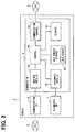
- the diagnosis AP server 6 has a control circuit 6a (corresponding to a computer), a vehicle information input/output portion 6b, a diagnosis information input/output portion 6c, a storage portion 6d (MEM), a WEB screen storage portion 6e, and a communication control circuit 6f (COM CNTL).
- the control circuit 6a is configured by a microcomputer having a CPU (central processing portion), a ROM (read only memory), and a RAM (random access memory).
- the control circuit 6a controls the overall operation of the diagnosis AP server 6 by executing a computer program stored in the ROM by the CPU.
- the vehicle information input/output portion 6b receives basic vehicle information and vehicle information (diagnostics and data) that are received by the communication AP server 8 from the communication terminal 4 through the M2M server 3.
- the vehicle information input/output portion 6b outputs the received basic vehicle information and the received vehicle information to the control circuit 6a.
- the diagnosis information input/output portion 6c receives the diagnosis information stored in the diagnosis DB server 7, and outputs the received diagnosis information to the control circuit 6a.
- the storage portion 6d stores various data required for the control circuit 6a to execute various data processing, and stores screen source data that corresponds to material data of a WEB screen as one piece of the stored data.
- the control circuit 6a reads the screen source data stored in the storage portion 6d, and builds the read screen source data to create the WEB screen, and stores the created WEB screen into the WEB screen storage portion 6e.
- the WEB screen represents a publicly available screen on the Internet with a WWW (World Wide Web) system.
- the WEB screen is a screen including text data, layout information based on an HTML (HyperText Markup Language), an image, a sound, and a moving picture embedded in a document.
- HTML HyperText Markup Language
- the control circuit 6a includes an acquisition item notification portion 61 (ITEM NOTF), an acquisition item determination portion 62(ITEM DETN), a diagnostics acquisition portion 63 (DIAG OBTAIN), a diagnosis avoidance portion 64 (DIAG AVOID), a data acquisition portion 65 (DATA OBTN), and a diagnosis result determination portion 66 (RESULT DETN) for each function.
- the control circuit 6a also includes a reference value determination portion 67 (STAND DETN), a diagnosis propriety condition determination portion 68 (DIAG COND DETN), a diagnosis enablement condition notification portion 69 (DIAG COND NOTF), and a drive mechanism temperature acquisition portion 70 (DRIVE TEMP OBTAIN) for each function.
- the control circuit 6a further includes a warm-up necessity determination portion 71 (WARM DETN), a warm-up necessary notification portion 72 (WARM NOTF), a data reacquisition necessity determination portion 73 (DATA REOBTN DETN), a data reacquisition necessary notification portion 74 (DATA REOBTN NOTIF), a sampling speed determination portion 75 (SAMPL DETN), and an operator operation determination portion 76 (OPRN DETN).
- WARM DETN warm-up necessity determination portion 71
- WARM NOTF warm-up necessary notification portion 72
- DATA REOBTN DETN data reacquisition necessity determination portion 73
- DATA REOBTN NOTIF data reacquisition necessary notification portion 74
- SAMPL DETN sampling speed determination portion
- OPRN DETN operator operation determination portion
- portion (or also referred to as means) classifies an interior of the control circuit 6a for convenience, focusing on the functions of the control circuit 6a. This does not mean that the interior of the control circuit 6a is physically divided into portions corresponding to the respective "portions". Therefore, the respective "portions" may be provided as parts of a computer program in software, and may be also provided by an IC chip or a large scale integrated circuit in hardware.
- the acquisition item notification portion 61 notifies the communication terminal 4 of an item of the vehicle information required for diagnosis, the vehicle information which is to be acquired from a vehicle 9.
- the acquisition item determination portion 62 determines the item of the vehicle information required for the diagnosis to be acquired from the vehicle 9, based on a content of a diagnosis or a classification of the vehicle 9.
- the diagnostics acquisition portion 63 acquires a diagnostics of the vehicle 9 as the vehicle information.
- the diagnosis avoidance portion 64 avoids execution of the diagnosis based on the vehicle information when the diagnostics to be diagnosed is acquired.
- the data acquisition portion 65 acquires data as the vehicle information.
- the diagnosis result determination portion 66 compares the data of the vehicle 9 with a reference value to determine a diagnosis result.
- the reference value determination portion 67 determines the reference value according to a content of the diagnosis and a temporal change of the vehicle 9 to be diagnosed, or the vehicle information acquired from the vehicle and stored in the past.
- the diagnosis propriety condition determination portion 68 determines whether a diagnosis propriety condition based on a sampling speed is present.
- the sampling speed represents a speed at which the communication terminal 4 acquires the data from the vehicle 9.
- the diagnosis enablement condition notification portion 69 notifies the communication terminal 4 of a diagnosis enablement condition when it is determined that the diagnosis propriety condition based on the sampling speed is present.
- the drive mechanism temperature acquisition portion 70 acquires a temperature of an engine of the vehicle 9. The engine corresponds to a drive mechanism.
- the warm-up necessity determination portion 71 determines whether warm-up of the engine is necessary, based on the temperature of the engine.
- the warm-up necessary notification portion 72 notifies the communication terminal 4 that the warm-up is necessary, when it is determined that the warm-up of the engine is necessary.
- the data reacquisition necessity determination portion 73 determines whether the reacquisition of the data is necessary, based on whether the sampling speed or the operation of the operator falls within a predetermined range (whether the operation is correct).
- the data reacquisition necessary notification portion 74 notifies the communication terminal 4 that the reacquisition of the data is necessary, when it is determined that the reacquisition of the data is necessary.
- the sampling speed determination portion 75 determines the sampling speed that indicates the speed at which the communication terminal 4 acquires the data from the vehicle 9.
- the operator operation determination portion 76 determines whether the operation of the operator falls within the predetermined range.
- the communication control circuit 6f controls a data communication between the diagnosis AP server 6 and the communication terminal 4 so as to transmit the WEB screen data configuring the WEB screen to the communication terminal 4, or so as to receive an operation signal transmitted from the communication terminal 4 in response to the operator operation of the communication terminal 4.
- the control circuit 6a receives an operation signal transmitted from the communication terminal 4 through the communication control circuit 6f.
- the control circuit 6a receives the vehicle information transmitted from the communication terminal 4 through the vehicle information input/output portion 6b.
- the control circuit 6a selects the WEB screen to be provided to the operator from the WEB screens stored in the WEB screen storage portion 6e (enabling the communication terminal 4 to display the WEB screen through the Internet 5), and prepares transmission of WEB screen data configuring the selected WEB screen.
- To provide the WEB screen by the server 2 means a state in which the communication terminal 4 enables to display the WEB screen through the Internet 5.
- the control circuit 6a causes the communication control circuit 6f to transmit the WEB screen data to the communication terminal 4.
- the communication terminal 4 enables to display the WEB screen provided by the server 2 through the Internet 5. The operator enables to browse the WEB screen created by the server 2 through the communication terminal 4.
- the M2M server 3 has an M2M platform server 3a.
- the M2M server 3 is connected to the server 2 through the Internet 5, and transmits and receives the basic vehicle information and the vehicle information with the server 2 through the Internet 5.
- the M2M server 3 is also connected through the Internet 5 to another server (not shown) having another function, for example, for managing the basic vehicle information and the vehicle information.
- the M2M server 3 transmits and receives the basic vehicle information and the vehicle information with the server having another function through the Internet 5.
- the communication terminal 4 is, for example, a tablet terminal that the operator who diagnoses the vehicle carries.
- the operator When the operator carries the communication terminal 4, the operator enables to diagnose the vehicle while browsing and confirming the WEB screen displayed on the communication terminal 4 without any limit of the operation area.
- the communication terminal 4 includes a control portion 4a, a connection connector 4b, a wide area wireless communication portion 4c, a command conversion portion 4d, a display portion 4e, an operation reception portion 4f, and a storage portion 4g.
- the control portion 4a is configured by a microcomputer having a CPU, a ROM, and a RAM.
- the control portion 4a controls the overall operation of the communication terminal 4 with execution of the computer program stored in the ROM by the CPU.
- the ROM is an example of a non-transitory tangible computer readable storage medium.
- the connection connector 4b is a connection terminal conforming to standards of an OBD (on board diagnostic) 2, and is connectable to a connection cable 10 acquiring the vehicle information from the vehicle 9.
- OBD on board diagnostic
- the wide area wireless communication portion 4c is connectable to the Internet 5 so as to receive (download) the WEB screen data from the server 2 when the wide area wireless communication portion is connected to the server 2 through the Internet 5, and so as to transmit the basic vehicle information and the vehicle information acquired from the vehicle 9 to the server 2 through the M2M server 3.
- the command conversion portion 4d converts (convert a protocol) a data format (protocol) of the basic vehicle information and the vehicle information transmitted and received between the communication terminal 4 and the vehicle 9 and a data format of the basic vehicle information and the vehicle information transmitted and received between the communication terminal 4 and the server 2 through the Internet 5.
- the display portion 4e is configured by, for example, a liquid crystal display (for example, a touch panel display) having a touch function.
- the control portion 4a Since a WEB browser (an Internet browser, a WWW browser) is incorporated into the control portion 4a, the control portion 4a builds the WEB screen data received by the wide area wireless communication portion 4c from the server 2 to display the WEB screen on the display portion 4e, or to follow a hyper link by the functions of the WEB browser.
- the operation reception portion 4f is configured by a touch switch (also referred to as an "icon") formed on the WEB screen displayed on, for example, the display portion 4e.
- the operation reception portion 4f receives setting and input made by the operation of the operator.
- the storage portion 4g stores various data required for the control portion 4a to execute various data processing.
- the vehicle 9 includes a connection connector 9a connected with the connection cable 10, a first control portion 11 a, a second control portion 12a, a third control portion 13a, and a fourth control portion 14a.
- the first control portion 11 a, the second control portion 12a, the third control portion 13a, and the fourth control portion 14a are connected to the connection connector 9a through a controller area network 9b (CAN).
- the first control portion 11 a detects on/off states of an accessory (ACC) switch 11 b, and displays the detection result on a first display portion 11c (an indicator).
- the second control portion 12a detects the amount of operation of an accelerator pedal 12b (the amount of depression), and displays the detection result on a second display portion 12c (a tachometer).
- the third control portion 13a detects the operation position of a wiper switch 13b (high speed, medium speed, low speed, off, or the like), and displays the detection result on a display portion 13c (an indicator).
- the fourth control portion 14a detects the operation position of a light switch 14b (all lights, vehicle width light, off, or the like), and displays the detection result on a fourth display portion 14c (an indicator).
- the detection result that indicates the on/off state of the ACC switch 11 b is displayed on the first display portion 11c, it may be possible for the operator to confirm the on/off state of the ACC switch 11 b.
- the detection result that indicates the amount of operation of the accelerator pedal 12b is displayed on the second display portion 12c, it may be possible that the operator confirms the amount of operation of the accelerator pedal 12b.
- the detection result that indicates the operation position of the wiper switch 13b is displayed on the display portion 13c, it may be possible that the operator confirms the operation position of the wiper switch 13b.
- the detection result that indicates the operation position of the light switch 14b is displayed on the fourth display portion 14c, it may be possible that the operator confirms the operation position of the light switch 14b.
- the communication terminal 4 When the communication terminal 4 is connected to the vehicle 9 through the connection cable 10, the communication terminal 4 transmits a basic vehicle information request or a vehicle information request to the vehicle 9, and receives (acquires) the basic vehicle information or the vehicle information from the vehicle 9.
- the basic vehicle information is information related to an ID (identification information) of an ECU (electronic control portion) mounted in, for example, the vehicle 9.
- the basic information is information for authenticating whether a data communication is established between the server 2 and the vehicle 9.
- the vehicle information is a diagnostics or data.
- the diagnostics is information related on a DTC (diagnostic trouble code, failure diagnosis code), an FFD (freeze frame data), or pending of various sensors and actuators that are held by an ECU provided in the vehicle 9.
- the data is information related to, for example, a rotation speed of the engine, a temperature of an engine coolant (cooling water), control states of the various sensors and actuators, the on/off state of the ACC switch 11 b, the operation amount of the accelerator pedal 12b, the operation position of the wiper switch 13b, and the operation position of the light switch 14b.
- the change in the vehicle state is reflected on the vehicle information. For example, when the operator operates (depresses) the accelerator pedal 12b, a variation in the amount of operation of the accelerator pedal 12b is reflected on the vehicle information.
- the server 2 receives the basic vehicle information and the vehicle information transmitted from the communication terminal 4 through the M2M server 3.
- the communication terminal 4 receives the WEB screen data transmitted from the server 2 without going through the M2M server 3.
- a route in which the basic vehicle information and the vehicle information acquired from the vehicle 9 are transmitted from the communication terminal 4, and received by the server 2 is different from a route in which the WEB screen data is transmitted from the server 2, and received by the communication terminal 4.
- the communication terminal 4 When the communication terminal 4 is connected to the server 2 through the Internet 5, the communication terminal 4 receives the WEB screen data from the server 2, and builds the received WEB screen data to enable the WEB screen to be displayed with using the functions of the WEB browser.
- the communication terminal 4 transmits a diagnosis start request to the server 2 from the wide area wireless communication portion 4c (B2).
- the server 2 Upon receiving the diagnosis start request transmitted from the communication terminal 4 by the communication control circuit 6f (C1), the server 2 selects a vehicle select screen from the WEB screens stored in the WEB screen storage portion 6e, and provides the vehicle select screen (C2).
- the communication terminal 4 receives the WEB screen data configuring the vehicle select screen from the server 2.
- the communication terminal 4 builds the received WEB screen data to display the vehicle select screen on the display portion 4e by the functions of the WEB browser.
- the operator browses and confirms the vehicle select screen displayed on the communication terminal 4 (B3), and selects the vehicle to be diagnosed, so that the operator proceeds to a subsequent process.
- the operator sets and inputs a registration number and a vehicle identification number to determine the vehicle 9 to be diagnosed.
- the new vehicle means a vehicle not to be diagnosed in the vehicle diagnosis system 1 in the past, and to be diagnosed for the first time.
- the operator selects the vehicle 9 from the vehicles having the registration numbers and the vehicle identification numbers registered, and determines the vehicle 9 that is diagnosed.
- the vehicle not newly registered means the vehicle to be diagnosed in the vehicle diagnosis system 1 in the past, which is to be diagnosed twice or more.
- the server 2 selects the vehicle (C3), and determines whether the diagnosis propriety condition according to the sampling speed is present (C4).
- diagnosis propriety condition the diagnosable item depends on the sampling speed.
- the server 2 selects a diagnosis enablement condition screen (DIAG COND DISP) from the WEB screens stored in the WEB screen storage portion 6e, and provides the selected diagnosis enablement condition screen (C5).
- DIG COND DISP diagnosis enablement condition screen
- the communication terminal 4 receives the WEB screen data configuring the diagnosis enablement condition screen from the server 2, and builds the received WEB screen data to display the diagnosis enablement condition screen on the display portion 4e by the functions of the WEB browser.
- the operator browses and confirms the diagnosis enablement condition screen displayed on the communication terminal 4 (B4), so that the operator grasps the diagnosis enablement condition.
- the server 2 selects a diagnosis start screen from the WEB screens stored in the WEB screen storage portion 6e, and provides the diagnosis start screen (C6).
- the communication terminal 4 receives the WEB screen data configuring the diagnosis start screen from the server 2, and builds the received WEB screen data to display the diagnosis start screen on the display portion 4e by the functions of the WEB browser.
- the operator browses and confirms the diagnosis start screen displayed on the communication terminal 4 (B5), so that the operator grasps an instruction for starting the diagnosis, and proceeds to a subsequent process.
- the server 2 transmits a diagnostics request to the communication terminal 4 from the communication AP server 8 through the M2M server 3 (C7).
- the communication terminal 4 Upon receiving the diagnostics request transmitted from the server 2 by the wide area wireless communication portion 4c (B6), the communication terminal 4 converts the received diagnostics request into a command, and transmits the diagnostics request subjected to the command conversion to the vehicle 9 through the connection cable 10 (B7).
- the vehicle 9 analyzes the received diagnostics request, and transmits a diagnostics designated by the diagnostics request to the communication terminal 4 through the connection cable 10 (A2).
- the communication terminal 4 Upon receiving the diagnostics transmitted from the vehicle 9 (B8), the communication terminal 4 converts the diagnostics into a command, and transmits the diagnostics subjected to the command conversion to the server 2 from the wide area wireless communication portion 4c through the M2M server 3 (B9).
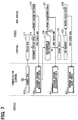
- the server 2 Upon receiving the diagnostics transmitted from the communication terminal 4 by the communication AP server 8 (C8), the server 2 determines whether the diagnostics is included in a diagnosis target (C9). When it is determined that the diagnostics is included in the diagnosis target (C9: YES), the server 2 cancels the subsequent processes (avoids the diagnosis). When it is determined that the diagnostics is not included in the diagnosis target (C9: NO), the server 2 transmits an engine (drive mechanism) water temperature request (TEMP REQ) from the communication AP server 8 to the communication terminal 4 through the M2M server 3 (C10).
- an engine drive mechanism
- TMP REQ water temperature request
- the communication terminal 4 Upon receiving the engine water temperature request transmitted from the server 2 by the wide area wireless communication portion 4c (B10), the communication terminal 4 converts the received engine water temperature request into a command, and transmits the engine water temperature request subjected to the command conversion to the vehicle 9 through the connection cable 10 (B11).
- the vehicle 9 Upon receiving the engine water temperature request transmitted from the communication terminal 4 (A3), the vehicle 9 transmits an engine water temperature that indicates a temperature of a coolant for cooling the engine to the communication terminal 4 through the connection cable 10 (A4).
- the communication terminal 4 Upon receiving the engine water temperature transmitted from the vehicle 9 (B12), the communication terminal 4 converts the engine water temperature into a command , and transmits the engine water temperature subjected to the command conversion from the wide area wireless communication portion 4c to the server 2 through the M2M server 3 (B13).
- the server 2 Upon receiving the engine water temperature transmitted from the communication terminal 4 by the communication AP server 8 (C11), the server 2 determines whether the engine water temperature is equal to or higher than a predetermined temperature (C12). When it is determined that the engine water temperature is not equal to or higher than the predetermined temperature (C12: NO), the server 2 selects a warm-up instruction screen from the WEB screens stored in the WEB screen storage portion 6e, and provides the warm-up instruction screen (C13).
- a predetermined temperature C12
- the server 2 returns to C10, and continues to transmit the engine water temperature request to the communication terminal 4 until it is determined that the engine water temperature is equal to or higher than a predetermine temperature, and repetitively executes the same process.
- the communication terminal 4 receives the WEB screen data configuring the warm-up instruction screen from the server 2, and builds the received WEB screen data to display the warm-up instruction screen on the display portion 4e by the functions of the WEB browser.
- the operator browses and confirms the warm-up instruction screen displayed on the communication terminal 4 (B14), so that the operator grasps that warm-up is necessary in starting the diagnosis.
- the server 2 When it is determined that the engine water temperature is equal to or higher than the predetermined temperature (C12: YES), the server 2 starts the diagnosis (C14), and transmits a data request (DATA REQ) from the communication AP server 8 to the communication terminal 4 through the M2M server 3 (C15).
- the communication terminal 4 Upon receiving the data request transmitted from the server 2 by the wide area wireless communication portion 4c (B15), the communication terminal 4 converts the received data request into a command, and transmits the data request subjected to the command conversion to the vehicle 9 through the connection cable 10 (B16).
- the vehicle 9 Upon receiving the data request transmitted from the communication terminal 4 (A5), the vehicle 9 transmits data designated by the received data request to the communication terminal 4 through the connection cable 10 (A6).
- the server 2 Upon starting the diagnosis, and transmitting the data request from the communication AP server 8 to the communication terminal 4 through the M2M server 3, the server 2 selects an operation instruction screen from the WEB screens stored in the WEB screen storage portion 6e, and provides the operation instruction screen (C16).
- the communication terminal 4 receives the WEB screen data configuring the operation instruction screen from the server 2, and builds the received WEB screen data to display the operation instruction screen on the display portion 4e by the functions of the WEB browser.
- the operator browses and confirms the operation instruction screen displayed on the communication terminal 4 (B17), grasps an instruction for advancing the diagnosis of an IG on, an engine start, an idle, a racing, and a full throttle racing as illustrated in FIG. 8 , and proceeds to the subsequent process.
- the operator changes a vehicle state according to an instruction described in the operation instruction screen (A7)
- data that reflects a change in the vehicle state is transmitted from the vehicle 9, and received by the server 2 through the communication terminal 4.
- the instruction described in the operation instruction screen is an instruction for operating (depressing) the accelerator pedal 12b, and when the operator operates the accelerator pedal 12b, data that indicates the rotation speed of the engine linked with the amount of operation of the accelerator pedal 12b is transmitted from the vehicle 9, and received by the server 2 through the communication terminal 4.
- the communication terminal 4 Upon receiving the data transmitted from the vehicle 9 (B18), the communication terminal 4 converts the received data into a command, and transmits the data subjected to the command conversion to the server 2 from the wide area wireless communication portion 4c through the M2M server 3 (B19).
- the server 2 Upon receiving the data transmitted from the communication terminal 4 by the communication AP server 8 (C17), the server 2 determines the sampling speed of the data (C18). When it is determined that the sampling speed of the data is not equal to or higher than a predetermined speed with respect to the various diagnosis conditions such as start-up or idling, the server 2 selects a diagnosis enable item screen from the WEB screens stored in the WEB screen storage portion 6e, and provides the diagnosis enable item screen (C19). When the server 2 provides the diagnosis enable item screen, the communication terminal 4 receives the WEB screen data configuring the diagnosis enable item screen from the server 2, and builds the received WEB screen data to display the diagnosis enable item screen on the display portion 4e by the functions of the WEB browser. The operator browses and confirms the diagnosis enable item screen displayed on the communication terminal 4 (B20), so that the operator grasps the diagnosable item.
- the server 2 acquires the operation conditions of the operator such as timing of on/off operation of the ACC switch 11 b or the amount of operation of the accelerator pedal 12b by the operator, which is acquired from the vehicle 9.
- the server 2 determines that the operation is improper in determining the diagnosis by the operator.
- the server 2 determines that the reliability of the data acquired from the vehicle 9 is low, and the reacquisition of the data is necessary (C20: YES), and selects a data reacquisition necessary screen from the WEB screens stored in the WEB screen storage portion 6e, and provides the data reacquisition necessary screen (C21).
- the server 2 returns to C14, and continues to transmit the data request to the communication terminal 4 until it is determined that the reacquisition of the data is not necessary, and repetitively executes the same process.
- the communication terminal 4 receives the WEB screen data configuring the data reacquisition necessary screen from the server 2, and builds the received WEB screen data to display the data reacquisition necessary screen on the display portion 4e by the functions of the WEB browser.
- the operator browses and confirms the data reacquisition necessary screen displayed on the communication terminal 4 (B21), and grasps that the data needs to be reacquired, so that the operator proceeds to a subsequent process. Incidentally, the operator may enable to cancel the reacquisition of the data.
- the server 2 determines that correct operation is performed when the operator determines the diagnosis, the server 2 determines that the reliability of the data acquired from the vehicle 9 is high, and the reacquisition of the data is not necessary (C20: NO), creates the diagnosis result based on the data acquired until now (C22), and ends the diagnosis (C23).
- the server 2 selects a frame (template) of a diagnosis result screen from the WEB screens stored in the WEB screen storage portion 6e, and provides the diagnosis result screen in which the present diagnosis result is described in the frame in question (C24).
- the communication terminal 4 receives the WEB screen data configuring the diagnosis result screen from the server 2, and builds the received WEB screen data to display the diagnosis result screen on the display portion 4e by the functions of the WEB browser.
- the operator browses and confirms the diagnosis result screen displayed on the communication terminal 4 (B22), so that the operator grasps the diagnosis result.
- FIG. 8 a case in which the server 2 diagnoses the engine (corresponding to the drive mechanism) will be described.
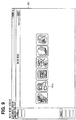
- FIG. 9 when the operator depresses a "diagnosis" icon 101 a when the communication terminal 4 displays a main menu screen 101, the communication terminal 4 transmits an operation signal indicating that the operator depresses the "diagnosis" icon 101 a to the server 2.
- the depression of the icon 101 a means the selection of the icon 101 a, and is not limited to the depressing operation.
- the server 2 Upon receiving the operation signal transmitted from the communication terminal 4, the server 2 transmits the WEB screen data to the communication terminal 4. Upon receiving the WEB screen data from the server 2, the communication terminal 4 selectively displays "engine”, “hybrid”, and “vehicle air conditioner” to be diagnosed on the main menu screen 101 as illustrated in FIG. 10 . When the operator selects, for example, "engine” as the diagnosis target, the communication terminal 4 transmits the operation signal indicating that the operator selects "engine” as the diagnosis target to the server 2.
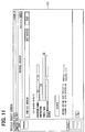
- the server 2 Upon receiving the operation signal transmitted from the communication terminal 4, the server 2 transmits the WEB screen data configuring a vehicle select screen 102 to the communication terminal 4. Upon receiving the WEB screen data from the server 2, the communication terminal 4 builds the WEB screen data, and displays the vehicle select screen 102 as illustrated in FIG. 11 .
- the communication terminal 4 transmits the operation signal indicating that the operator selects the vehicle 9 to be diagnosed to the server 2.
- vehicle A indicates a vehicle name.
- PPP12-XXXXX indicates a vehicle identification number.
- the server 2 Upon receiving the operation signal transmitted from the communication terminal 4, the server 2 transmits the WEB screen data configuring a diagnosis start screen 103 to the communication terminal 4.
- the communication terminal 4 Upon receiving the WEB screen data from the server 2, the communication terminal 4 builds the received WEB screen data, and displays the diagnosis start screen 103 as illustrated in FIG. 12 .
- the operator grasps that instructions when starting the diagnosis are "P-range”, “after engine warm-up”, “IGON (engine stop)", “electric load off”, and so on.
- the communication terminal 4 transmits an operation signal indicating that the operator depresses the start button 103a to the server 2.
- the server 2 Upon receiving the operation signal transmitted from the communication terminal 4, the server 2 transmits a data request for acquiring data that indicates the present temperature (engine water temperature) of a coolant in the engine to the communication terminal 4. Upon receiving the data that indicates the present temperature of the coolant in the engine from the communication terminal 4, when the server 2 determines that the present temperature of the coolant in the engine does not reach a predetermined temperature, the server 2 transmits the WEB screen data configuring a warm-up instruction screen 104 to the communication terminal 4. Upon receiving the WEB screen data from the server 2, the communication terminal 4 builds the received WEB screen data, and displays the warm-up instruction screen 104 as illustrated in FIG. 13 .
- the operator grasps the present temperature ("55°C” is illustrated in FIG. 13 ) of the coolant in the engine.
- the operator grasps that (i) warm-up operation needs to be implemented for a reason that the present temperature of the coolant in the engine does not reach a predetermined temperature ("70°C” is illustrated in FIG. 13 ), and (ii) a subsequent procedure is automatically displayed when the temperature of the coolant in the engine reaches the predetermined temperature.
- the server 2 does not transmit the WEB screen data configuring the warm-up instruction screen 104 to the communication terminal 4, and the communication terminal 4 does not display the warm-up instruction screen 104.
- the server 2 monitors whether the temperature of the coolant in the engine reaches the predetermined temperature, and transmits the WEB screen data configuring a first operation instruction screen 105 to the communication terminal 4 when it is determined that the temperature of the coolant in the engine reaches the predetermined temperature.
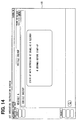
- the communication terminal 4 Upon receiving the WEB screen data from the server 2, the communication terminal 4 builds the received WEB screen data, and displays the first operation instruction screen 105 as illustrated in FIG. 14 .
- the operator grasps that the subsequent procedure is operation of depressing the brake for start-up, so that the operator grasps timing at which the brake is depressed for start-up.
- the server 2 transmits a data request that indicates an item of data required for diagnosis associated with the first operation instruction screen 105 to the communication terminal 4. Specifically, as illustrated in FIG. 6 , the server 2 transmits a data request that indicates several items including a rotation speed of the engine to the communication terminal 4 when diagnosing the start-up of the engine. Since the items of data required for the diagnosis are notified to the communication terminal 4 from the server 2, the operator does not need to set and input the items of the data required for the diagnosis.
- the communication terminal 4 acquires data that indicates several items including the rotation speed of the engine designated according to the data request from the vehicle 9
- the communication terminal 4 transmits the acquired data to the server 2 through the M2M server 3 in real time without storing the acquired data.
- the communication terminal 4 functions as a relay device when the server 2 acquires data from the vehicle 9.
- the server 2 When the server 2 provides the first operation instruction screen 105 for facilitating the start-up of the engine with the depression of the brake, the server 2 instructs timing at which the operator starts up the engine by countdown. A route in which the basic vehicle information and the vehicle information are transmitted from the communication terminal 4, and received by the server 2 is different from a route in which the WEB screen data is transmitted from the server 2, and received by the communication terminal 4. For that reason, when the communication terminal 4 transmits the data associated with the start-up when the server 2 does not complete a preparation for receiving the data associated with the start-up from the communication terminal 4, the server 2 may not receive the data.
- the server 2 adjusts (establishes synchronization) the timing at which the operator starts up the engine in the first operation instruction screen 105 so that the operator starts up the engine after the server 2 has completed the preparation for receiving the data associated with the start-up from the communication terminal 4.
- the present disclosure is not limited to a configuration in which the timing at which the operator starts up the engine is instructed by countdown, but timing to display the first operation instruction screen 105 may be adjusted. In a second operation instruction screen 106 and a third operation instruction screen 107 which will be described later, timing at which the operator operates is adjusted similarly.
- the server 2 monitors whether the operator depresses the brake to start up the engine, and when it is determined that the operator depresses the brake to start up the engine, the server 2 transmits the WEB screen data configuring the second operation instruction screen 106 to the communication terminal 4.
- the communication terminal 4 Upon receiving the WEB screen data from the server 2, the communication terminal 4 displays the second operation instruction screen 106 as illustrated in FIG. 15 .
- the operator grasps that the subsequent procedure is operation for allowing the rotation speed of the engine to rise up to a predetermined speed ("2000 rpm" is illustrated in FIG. 15 ), and be kept constant.
- the server 2 transmits the data request that indicates the items of the data required for the diagnosis associated with the second operation instruction screen 106 to the communication terminal 4. Specifically, as illustrated in FIG. 6 , the server 2 transmits the data request that indicates several items including the rotation speed of the engine to the communication terminal 4 even when diagnosing racing. Similarly in this case, since the items of data required for the diagnosis are notified to the communication terminal 4 from the server 2, the operator does not need to set and input the items of the data required for the diagnosis. Similarly, in this case, when the communication terminal 4 acquires data that indicates several items including the rotation speed of the engine designated according to the data request from the vehicle 9, the communication terminal 4 transmits the acquired data to the server 2 through the M2M server 3 in real time without storing the acquired data.
- a scale 106b that indicates a range of the rotation speed of the engine ("0 to 5000 rpm" is illustrated in FIG. 15 )
- a target line 106c that indicates a target
- a target area 106d around the target line 106c and a bar 106e that indicates the rotation speed of the engine are displayed so that the operator confirms the rotation speed of the engine.
- the scale 106b, the target line 106c, the target area 106d, and the bar 106e may be displayed with colors, and may be displayed in gray scale or monochrome.
- the vehicle information including the rotation speed of the engine according to the amount of operation is received by the server 2 from the vehicle 9 through the communication terminal 4 and the M2M server 3 with the result that the rotation speed of the engine is reflected on the second operation instruction screen 106.
- a length of the bar 106e that indicates the rotation speed of the engine is extended and contracted on the second operation instruction screen 106 according to the operation of the accelerator pedal 12b by the operator. In that case, timing at which the second operation instruction screen 106 is displayed is adjusted so that the operator operates the accelerator pedal 12b after the server 2 has completed the preparation for receiving the data that indicates the rotation speed of the engine.
- the length of the bar 106e that indicates the rotation speed of the engine is expanded and contracted on the second operation instruction screen 106 in conjunction with the operation of the accelerator pedal 12b by the operator. It may be possible to prevent a situation in which the length of the bar 106e is not expanded and contracted although the operator operates the accelerator pedal 12b, or a situation in which the length of the bar 106e is expanded or contracted later than the timing at which the operator operates the accelerator pedal 12b. It may be possible to avoid that the operator feels uncomfortable in advance.
- the length of the bar 106e is expanded and contracted according to the amount of operation of the accelerator pedal 12b by the operator, even when a tachometer (rotation speed meter that indicates the rotation speed of the engine) is not implemented in the vehicle 9 to be diagnosed, it may be possible to confirm the rotation speed of the engine with the browse and confirmation of the second operation instruction screen 106. Since the second operation instruction screen 106 is provided by the WEB screens, it may be possible to arbitrarily set a resolution (scale) of the scale 106b.
- the communication terminal 4 transmits an operation signal indicating that the operator depresses the measurement start button 106a to the server 2.
- the server 2 Upon receiving the operation signal transmitted from the communication terminal 4, the server 2 transmits the WEB screen data configuring the third operation instruction screen 107 to the communication terminal 4.
- the communication terminal 4 Upon receiving the WEB screen data from the server 2, the communication terminal 4 builds the received WEB screen data, and displays a third operation instruction screen 107 as illustrated in FIG. 17 .
- the operator grasps that the subsequent procedure is operation for fully depressing the accelerator (the amount of depressing the accelerator pedal 12b is maximized).
- a scale 107a, a target line 107b, a target area 107c, and a bar 107d are displayed. Thus, it may be possible for the operator to confirm the rotation speed of the engine.
- the server 2 transmits the data request that indicates the items of the data required for the diagnosis associated with the third operation instruction screen 107 to the communication terminal 4. Specifically, as illustrated in FIG. 6 , the server 2 transmits the data request that indicates several items including the rotation speed of the engine and an absolute opening of a throttle to the communication terminal 4 when diagnosing full throttle racing. Similarly in this case, since the items of data required for the diagnosis are notified to the communication terminal 4 from the server 2, the operator does not need to set and input the items of the data required for the diagnosis.
- the communication terminal 4 when the communication terminal 4 acquires data that indicates several items including the rotation speed of the engine and the absolute opening of the throttle designated according to the data request from the vehicle 9, the communication terminal 4 transmits the acquired data to the server 2 through the M2M server 3 in real time without storing the acquired data.
- the server 2 transmits the WEB screen data configuring a diagnosis result screen 108 to the communication terminal 4.
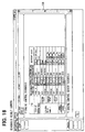
- the communication terminal 4 Upon receiving the WEB screen data from the server 2, the communication terminal 4 builds the received WEB screen data, and displays the diagnosis result screen 108 as illustrated in FIG. 18 .
- the operator grasps the diagnosis result obtained by performing the series of diagnoses.
- the communication terminal 4 displays the diagnosis result screen 108 scrollably.
- the communication terminal 4 may print and output the diagnosis result to a predetermined size of a sheet 201.
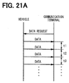
- FIG. 21A to FIG. 21C illustrate a relationship between the sampling speed and the diagnosable items.
- the sampling speed is indicated by an time interval (t1, t2, ...) of a transmission timing when the vehicle 9 transmits the data to the communication terminal 4 in response to the reception of the data request from the communication terminal 4 (refer to FIG. 21A ). Since the determination required for the diagnosis is enabled even when the sampling speed is low (even when the time interval of the transmission timing of the data is long), for example, with respect to data of an intake pipe pressure and idle in the start-up, the server 2 determines that the reacquisition of the data is unnecessary.
- the server 2 Since the determination required for the diagnosis is disabled when the sampling speed is low (when the time interval of the transmission timing of the data is long), for example, with respect to data of startability and racing in the start-up, the server 2 determines that the diagnosis of the startability and racing in the start-up is disabled when the sampling speed is equal to or higher than a predetermined time (for example, V1 [ms] or higher, or V2 [ms] or higher in FIG. 21 C) .
- a predetermined time for example, V1 [ms] or higher, or V2 [ms] or higher in FIG. 21 C
- FIG. 22 illustrates a reference value in determining the diagnosis result.
- the server 2 holds a table of the reference value for each of characteristics (characteristics such as a vehicle model, an engine model, a drive system (2WD/4WD), and a transmission) of the vehicle, and determines the reference value according to a temporal change (vehicle age) of the vehicle.
- characteristics such as a vehicle model, an engine model, a drive system (2WD/4WD), and a transmission
- the server 2 determines that the diagnosis result is normal when the coolant temperature falls within a range from "A1" to "A2", and that the diagnosis result is abnormal when the coolant temperature falls outside the range from "A1" to "A2".
- the server 2 determines that the diagnosis result is normal when the coolant temperature falls within a range from "A3" to "A4", and that the diagnosis result is abnormal when the coolant temperature falls outside the range from "A3" to "A4".
- the server 2 has a function of storing temporal changes of the vehicle 9 and other vehicles 9 of the same type such as the same engine model, or actual performances of the diagnosis results determined in the past, determining the reference value of a determination criterion or the travel distance, or dynamically determining the reference value based on the vehicle information acquired from the vehicle 9 in the past.
- the server 2 notifies the communication terminal 4 of the items of the date required for the diagnosis to be acquired from the vehicle 9.
- the operator does not need to operate the communication terminal 4, and set and input the items of the data required for the diagnosis, and it may be possible to reduce the burden on the operator who diagnoses the vehicle 9.
- the communication terminal 4 functions as the relay device, and transmits (relays) the data acquired by the communication terminal 4 from the vehicle 9 to the server 2 in real time, it may be possible to quickly obtain the diagnosis result.
- the server 2 provides the WEB screen including the instruction to the operator who diagnoses the vehicle 9 to the communication terminal 4 through the Internet 5. With the browse and the confirmation of the WEB screen displayed on the communication terminal 4, the operator who deals with the communication terminal 4 grasps the instruction to the operator, and diagnoses the vehicle 9 according to the instruction. In this case, for example, even with complicated instructions associated with multiple procedures for changing the vehicle state constantly, the server 2 updates the WEB screens one by one, it may be possible to appropriately give the complicated instruction to the operator.
- the WEB screen is created for each of a wide variety of characteristics (characteristics such as a vehicle model, an engine model, a drive system (2WD/4WD), and a transmission) of the vehicle 9, and there is no need to prepare the multiple communication terminals 4 for each of the characteristics of the vehicle 9 to be diagnosed.
- Any communication terminal 4 having the function (WEB browser) for displaying the WEB screen may be applicable, and it may be possible that the communication terminal 4 become generalized and easily realized.
- the communication terminal 4 is connected directly to the vehicle, and the communication terminal 4 acquires the vehicle information directly from the vehicle.
- a communication terminal is connected to a vehicle through a dedicated vehicle connection terminal, and the communication terminal 4 acquires vehicle information from the vehicle through a vehicle connection terminal.
- a vehicle connection terminal 21 includes a control portion 21 a that controls the overall operation, a connection connector 21 b and a command conversion portion 21 c corresponding to the connection connector 4b and the command conversion portion 4d described in the first embodiment, respectively, and a BT communication portion 21 d that performs a Bluetooth (registered trademark) communication with a communication terminal 22.
- the communication terminal 22 includes a control portion 22a that controls the overall operation, a BT communication portion 22b that performs a Bluetooth communication with the vehicle connection terminal 21, and a wide area wireless communication portion 22c, a display portion 22d, an operation reception portion 22e, and a storage portion 22f corresponding to the wide area wireless communication portion 4c, the display portion 4e, the operation reception portion 4f, and the storage portion 4g described in the first embodiment, respectively.
- the present disclosure is not limited to a configuration in which the vehicle connection terminal 21 and the communication terminal 22 are connected to each other by Bluetooth, but is applicable to a configuration in which the vehicle connection terminal 21 and the communication terminal 22 are connected to each other by another wireless communication system (wireless LAN, etc.).
- the vehicle connection terminal 21 and the communication terminal 22 may be connected to each other by wire. Even in the configuration where the function of the communication terminal 4 described in the first embodiment is shared to two terminals of the vehicle connection terminal 21 and the communication terminal 22, the same effects as those in the first embodiment are obtained.
- the present disclosure is not limited to only the embodiments, but may be modified or expanded as follows.
- the present disclosure is not limited to a case of diagnosing the engine, but may be applied to a case of diagnosing another mechanism such as a vehicle air conditioner.
- the diagnosis of the engine is not limited to a series of flow of the diagnostics, the start-up, the idle, the racing, and the full throttle racing, but may be divided into only the diagnostics, only the start-up, or only the idle, or may be performed by the combination of at least two of the start-up and the idle.
- the instruction to the operator on the WEB screen is not limited to only the characters, but may be performed by the combination of the characters with an image, or may be performed by a still image or a moving picture.
- the instruction may be performed by outputting a voice in conjunction with, for example, an image. With the combination with the image, the effect of more precisely giving the instruction to the operator may be expected.
- the connection between the connection connector 9a and each of the first control portion 11 a to the fourth control portion 14a is not limited to the CAN, but may be performed by the use of another communication system such as an in-vehicle Ethernet (registered trademark) or a FlexRay (registered trademark).
- the communication terminal transmits the vehicle information acquired from the vehicle to the server.
- the server analyzes the vehicle information received from the communication terminal to diagnose the vehicle.
- the acquisition item notification portion 61 notifies the communication terminal of items of the vehicle information required for diagnosis to be acquired from the vehicle.
- the communication terminal acquires the vehicle information from the vehicle according to the items of the vehicle information notified from the server, and transmits the acquired vehicle information to the server in real time.
- the server notifies the communication terminal of the items of the vehicle information required for the diagnosis to be acquired from the vehicle, the operator does not need to operate the communication terminal, and set and input the items of the vehicle information required for the diagnosis. It may be possible to reduce the burden on the operator who diagnoses the vehicle. Since the vehicle information acquired by the communication terminal from the vehicle is transmitted to the server in real time, it may be possible to quickly obtain the diagnosis result.
Landscapes
- Physics & Mathematics (AREA)
- General Physics & Mathematics (AREA)
- Vehicle Cleaning, Maintenance, Repair, Refitting, And Outriggers (AREA)
Abstract
Description
- The present application is based on
Japanese patent application No. 2013-89664 filed on April 22, 2013 - The present disclosure relates to a vehicle diagnosis system, a server, and a computer program. The vehicle diagnosis system has a communication terminal that transmits vehicle information acquired from a vehicle to a server and the server that analyzes the vehicle information received from the communication terminal to diagnose the vehicle.
- As a vehicle diagnosis system in which the server and the communication terminal cooperate with each other to diagnose the vehicle, the server transmits an instruction to an operator (for example, a mechanic) who diagnoses the vehicle to the communication terminal, and the communication terminal displays the instruction to the operator (for example, referring to
patent literature 1 and patent literature 2). - The inventors of the present application have found the following regarding a vehicle diagnosis system. In the vehicle diagnosis system in which the server and the communication terminal cooperate with each other to diagnose the vehicle, the operator operates the communication terminal to set and enter items of vehicle information required for diagnosis, the vehicle information being acquired from the vehicle. According to this configuration, the operation of setting and entering the items of the vehicle information may be a burden on the operator. Since the communication terminal stores the vehicle information acquired from the vehicle once, it may take time for the server to acquire the vehicle information, and the diagnosis result may not be obtained quickly.
-
- Patent literature 1:
JP H10-197285 A - Patent literature 2:
JP 2003-132168 A - It is an object of the present disclosure to provide a vehicle diagnosis system, a server, and a computer program, which are capable of quickly obtaining a diagnosis result while reducing a burden on an operator who diagnoses a vehicle.
- A vehicle diagnosis system according to a first example of the present disclosure includes a communication terminal transmitting vehicle information acquired from a vehicle, and a server analyzing the vehicle information received from the communication terminal to diagnose the vehicle. The server includes an acquisition item notification portion that notifies the communication terminal of an item of the vehicle information required for diagnosis, which is to be acquired from the vehicle. The communication terminal acquires the vehicle information from the vehicle according to the item of the vehicle information notified from the server, and transmits the acquired vehicle information to the server in real time.
- According to a second example of the present disclosure, a server providing a vehicle diagnosis system together with a communication terminal that transmits vehicle information acquired from a vehicle to the server, and analyzing the vehicle information received from the communication terminal to diagnose the vehicle, is provided. The server includes an acquisition item notification portion that notifies the communication terminal of an item of the vehicle information required for diagnosis to be acquired from the vehicle.
- According to a third example of the present disclosure, a computer program that causes a computer to notify a communication terminal of an item of vehicle information required for diagnosis to be acquired from a vehicle. The computer is provided to a server. The server provides a vehicle diagnosis system together with the communication terminal transmitting the vehicle information acquired from the vehicle to the server, and that analyzes the vehicle information received from the communication terminal to diagnose the vehicle.
- According to the vehicle diagnosis system, the server, and the computer program, the communication terminal transmits the vehicle information acquired from the vehicle to the server. The server analyzes the vehicle information received from the communication terminal to diagnose the vehicle. In the server, the acquisition item notification portion notifies the communication terminal of items of the vehicle information required for diagnosis to be acquired from the vehicle. The communication terminal acquires the vehicle information from the vehicle according to the items of the vehicle information notified from the server, and transmits the acquired vehicle information to the server in real time. Thus, it may be possible to reduce a burden on the operator diagnosing the vehicle, and to quickly obtain the diagnosis result.
- The above and other objects, features and advantages of the present disclosure will become more apparent from the following detailed description made with reference to the accompanying drawings. In the drawings:
-
FIG. 1 is a diagram illustrating an overall configuration of a first embodiment in the present disclosure; -
FIG. 2 is a functional block diagram illustrating a configuration of a server; -
FIG. 3 is a functional block diagram illustrating a configuration of a diagnosis AP server; -
FIG. 4 is a functional block diagram illustrating a configuration of a vehicle and a communication terminal; -
FIG. 5 is a diagram illustrating a part of a flow of processing; -
FIG. 6 is a diagram illustrating a part of the flow of processing; -
FIG. 7 is a diagram illustrating a part of the flow of processing; -
FIG. 8 is a diagram illustrating the transition of an engine rotation speed, the transition of screens, and vehicle information acquired from the vehicle; -
FIG. 9 is a diagram illustrating a part of a main menu screen; -
FIG. 10 is a diagram illustrating a part of the main menu screen; -
FIG. 11 is a diagram illustrating a vehicle select screen; -
FIG. 12 is a diagram illustrating a diagnosis start screen; -
FIG. 13 is a diagram illustrating a warm-up instruction screen; -
FIG. 14 is a diagram illustrating a first operation instruction screen; -
FIG. 15 is a diagram illustrating a second operation instruction screen; -
FIG. 16 is a diagram illustrating the second operation instruction screen; -
FIG. 17 is a diagram illustrating a third operation instruction screen; -
FIG. 18 is a diagram illustrating a first diagnosis result screen; -
FIG. 19 is a diagram illustrating a second diagnosis result screen; -
FIG. 20 is a diagram illustrating a sheet on which the diagnosis result is printed and output; -
FIG. 21A is a diagram illustrating a relationship between a sampling speed and a diagnosable item; -
FIG. 21B is a diagram illustrating a relationship between the sampling speed and the diagnosable item; -
FIG. 21C is a diagram illustrating a relationship between the sampling speed and the diagnosable item; -
FIG. 22 is a diagram illustrating an upper limit and a lower limit of a reference value; and -
FIG. 23 is an overall configuration diagram illustrating a second embodiment of the present disclosure. - A first embodiment of the present disclosure will be described with reference to
FIG. 1 to FIG. 22 . As illustrated inFIG. 1 , avehicle diagnosis system 1 includes aserver 2, a machine-to-machine (M2M)server 3, and acommunication terminal 4, which are configured to be connectable to each other through the Internet 5. - The
server 2 has a diagnosis application server 6 (diagnosis AP server), a diagnosis database server 7 (diagnosis DB server), and a communication application server 8 (communication AP server) for each function. The diagnosis DB server 7 stores diagnosis information required for diagnosis of a vehicle. Thediagnosis AP server 6 reads the diagnosis information stored in the diagnosis DB server 7, and diagnoses the vehicle with the diagnosis information. Thecommunication AP server 8 controls a data communication between theserver 2 and theM2M server 3. - As illustrated in
FIG. 2 , thediagnosis AP server 6 has acontrol circuit 6a (corresponding to a computer), a vehicle information input/output portion 6b, a diagnosis information input/output portion 6c, astorage portion 6d (MEM), a WEBscreen storage portion 6e, and acommunication control circuit 6f (COM CNTL). Thecontrol circuit 6a is configured by a microcomputer having a CPU (central processing portion), a ROM (read only memory), and a RAM (random access memory). Thecontrol circuit 6a controls the overall operation of thediagnosis AP server 6 by executing a computer program stored in the ROM by the CPU. - The vehicle information input/
output portion 6b receives basic vehicle information and vehicle information (diagnostics and data) that are received by thecommunication AP server 8 from thecommunication terminal 4 through theM2M server 3. The vehicle information input/output portion 6b outputs the received basic vehicle information and the received vehicle information to thecontrol circuit 6a. The diagnosis information input/output portion 6c receives the diagnosis information stored in the diagnosis DB server 7, and outputs the received diagnosis information to thecontrol circuit 6a. Thestorage portion 6d stores various data required for thecontrol circuit 6a to execute various data processing, and stores screen source data that corresponds to material data of a WEB screen as one piece of the stored data. - The
control circuit 6a reads the screen source data stored in thestorage portion 6d, and builds the read screen source data to create the WEB screen, and stores the created WEB screen into the WEBscreen storage portion 6e. Incidentally, the WEB screen represents a publicly available screen on the Internet with a WWW (World Wide Web) system. The WEB screen is a screen including text data, layout information based on an HTML (HyperText Markup Language), an image, a sound, and a moving picture embedded in a document. - As illustrated in
FIG. 3 , thecontrol circuit 6a includes an acquisition item notification portion 61 (ITEM NOTF), an acquisition item determination portion 62(ITEM DETN), a diagnostics acquisition portion 63 (DIAG OBTAIN), a diagnosis avoidance portion 64 (DIAG AVOID), a data acquisition portion 65 (DATA OBTN), and a diagnosis result determination portion 66 (RESULT DETN) for each function. Thecontrol circuit 6a also includes a reference value determination portion 67 (STAND DETN), a diagnosis propriety condition determination portion 68 (DIAG COND DETN), a diagnosis enablement condition notification portion 69 (DIAG COND NOTF), and a drive mechanism temperature acquisition portion 70 (DRIVE TEMP OBTAIN) for each function. Thecontrol circuit 6a further includes a warm-up necessity determination portion 71 (WARM DETN), a warm-up necessary notification portion 72 (WARM NOTF), a data reacquisition necessity determination portion 73 (DATA REOBTN DETN), a data reacquisition necessary notification portion 74 (DATA REOBTN NOTIF), a sampling speed determination portion 75 (SAMPL DETN), and an operator operation determination portion 76 (OPRN DETN). - Incidentally, the above "portion (or also referred to as means)" classifies an interior of the
control circuit 6a for convenience, focusing on the functions of thecontrol circuit 6a. This does not mean that the interior of thecontrol circuit 6a is physically divided into portions corresponding to the respective "portions". Therefore, the respective "portions" may be provided as parts of a computer program in software, and may be also provided by an IC chip or a large scale integrated circuit in hardware. - The acquisition
item notification portion 61 notifies thecommunication terminal 4 of an item of the vehicle information required for diagnosis, the vehicle information which is to be acquired from avehicle 9. The acquisition item determination portion 62 determines the item of the vehicle information required for the diagnosis to be acquired from thevehicle 9, based on a content of a diagnosis or a classification of thevehicle 9. The diagnostics acquisition portion 63 acquires a diagnostics of thevehicle 9 as the vehicle information. Thediagnosis avoidance portion 64 avoids execution of the diagnosis based on the vehicle information when the diagnostics to be diagnosed is acquired. Thedata acquisition portion 65 acquires data as the vehicle information. The diagnosisresult determination portion 66 compares the data of thevehicle 9 with a reference value to determine a diagnosis result. The referencevalue determination portion 67 determines the reference value according to a content of the diagnosis and a temporal change of thevehicle 9 to be diagnosed, or the vehicle information acquired from the vehicle and stored in the past. - The diagnosis propriety condition determination portion 68 determines whether a diagnosis propriety condition based on a sampling speed is present. The sampling speed represents a speed at which the
communication terminal 4 acquires the data from thevehicle 9. The diagnosis enablement condition notification portion 69 notifies thecommunication terminal 4 of a diagnosis enablement condition when it is determined that the diagnosis propriety condition based on the sampling speed is present. The drive mechanism temperature acquisition portion 70 acquires a temperature of an engine of thevehicle 9. The engine corresponds to a drive mechanism. The warm-upnecessity determination portion 71 determines whether warm-up of the engine is necessary, based on the temperature of the engine. The warm-upnecessary notification portion 72 notifies thecommunication terminal 4 that the warm-up is necessary, when it is determined that the warm-up of the engine is necessary. - The data reacquisition
necessity determination portion 73 determines whether the reacquisition of the data is necessary, based on whether the sampling speed or the operation of the operator falls within a predetermined range (whether the operation is correct). The data reacquisition necessary notification portion 74 notifies thecommunication terminal 4 that the reacquisition of the data is necessary, when it is determined that the reacquisition of the data is necessary. The samplingspeed determination portion 75 determines the sampling speed that indicates the speed at which thecommunication terminal 4 acquires the data from thevehicle 9. The operatoroperation determination portion 76 determines whether the operation of the operator falls within the predetermined range. - The
communication control circuit 6f controls a data communication between thediagnosis AP server 6 and thecommunication terminal 4 so as to transmit the WEB screen data configuring the WEB screen to thecommunication terminal 4, or so as to receive an operation signal transmitted from thecommunication terminal 4 in response to the operator operation of thecommunication terminal 4. Thecontrol circuit 6a receives an operation signal transmitted from thecommunication terminal 4 through thecommunication control circuit 6f. Thecontrol circuit 6a receives the vehicle information transmitted from thecommunication terminal 4 through the vehicle information input/output portion 6b. Then, thecontrol circuit 6a selects the WEB screen to be provided to the operator from the WEB screens stored in the WEBscreen storage portion 6e (enabling thecommunication terminal 4 to display the WEB screen through the Internet 5), and prepares transmission of WEB screen data configuring the selected WEB screen. To provide the WEB screen by theserver 2 means a state in which thecommunication terminal 4 enables to display the WEB screen through theInternet 5. - When a condition for transmitting the WEB screen data that is prepared for the transmission is established, the
control circuit 6a causes thecommunication control circuit 6f to transmit the WEB screen data to thecommunication terminal 4. With the transmission of the WEB screen data from theserver 2 to thecommunication terminal 4, thecommunication terminal 4 enables to display the WEB screen provided by theserver 2 through theInternet 5. The operator enables to browse the WEB screen created by theserver 2 through thecommunication terminal 4. - The
M2M server 3 has anM2M platform server 3a. TheM2M server 3 is connected to theserver 2 through theInternet 5, and transmits and receives the basic vehicle information and the vehicle information with theserver 2 through theInternet 5. TheM2M server 3 is also connected through theInternet 5 to another server (not shown) having another function, for example, for managing the basic vehicle information and the vehicle information. TheM2M server 3 transmits and receives the basic vehicle information and the vehicle information with the server having another function through theInternet 5. - The
communication terminal 4 is, for example, a tablet terminal that the operator who diagnoses the vehicle carries. When the operator carries thecommunication terminal 4, the operator enables to diagnose the vehicle while browsing and confirming the WEB screen displayed on thecommunication terminal 4 without any limit of the operation area. As illustrated inFIG. 4 , thecommunication terminal 4 includes acontrol portion 4a, aconnection connector 4b, a wide areawireless communication portion 4c, acommand conversion portion 4d, adisplay portion 4e, anoperation reception portion 4f, and astorage portion 4g. - The
control portion 4a is configured by a microcomputer having a CPU, a ROM, and a RAM. Thecontrol portion 4a controls the overall operation of thecommunication terminal 4 with execution of the computer program stored in the ROM by the CPU. The ROM is an example of a non-transitory tangible computer readable storage medium. Theconnection connector 4b is a connection terminal conforming to standards of an OBD (on board diagnostic) 2, and is connectable to aconnection cable 10 acquiring the vehicle information from thevehicle 9. In the present embodiment, a configuration in which thecommunication terminal 4 and thevehicle 9 are connected to each other through theconnection cable 10 in a wired manner is described. Alternatively, thecommunication terminal 4 and thevehicle 9 may be connected to each other wirelessly. - The wide area
wireless communication portion 4c is connectable to theInternet 5 so as to receive (download) the WEB screen data from theserver 2 when the wide area wireless communication portion is connected to theserver 2 through theInternet 5, and so as to transmit the basic vehicle information and the vehicle information acquired from thevehicle 9 to theserver 2 through theM2M server 3. Thecommand conversion portion 4d converts (convert a protocol) a data format (protocol) of the basic vehicle information and the vehicle information transmitted and received between thecommunication terminal 4 and thevehicle 9 and a data format of the basic vehicle information and the vehicle information transmitted and received between thecommunication terminal 4 and theserver 2 through theInternet 5. Thedisplay portion 4e is configured by, for example, a liquid crystal display (for example, a touch panel display) having a touch function. - Since a WEB browser (an Internet browser, a WWW browser) is incorporated into the
control portion 4a, thecontrol portion 4a builds the WEB screen data received by the wide areawireless communication portion 4c from theserver 2 to display the WEB screen on thedisplay portion 4e, or to follow a hyper link by the functions of the WEB browser. Theoperation reception portion 4f is configured by a touch switch (also referred to as an "icon") formed on the WEB screen displayed on, for example, thedisplay portion 4e. Theoperation reception portion 4f receives setting and input made by the operation of the operator. Thestorage portion 4g stores various data required for thecontrol portion 4a to execute various data processing. - The
vehicle 9 includes aconnection connector 9a connected with theconnection cable 10, afirst control portion 11 a, asecond control portion 12a, athird control portion 13a, and afourth control portion 14a. Thefirst control portion 11 a, thesecond control portion 12a, thethird control portion 13a, and thefourth control portion 14a are connected to theconnection connector 9a through acontroller area network 9b (CAN). Thefirst control portion 11 a detects on/off states of an accessory (ACC) switch 11 b, and displays the detection result on afirst display portion 11c (an indicator). Thesecond control portion 12a detects the amount of operation of anaccelerator pedal 12b (the amount of depression), and displays the detection result on asecond display portion 12c (a tachometer). Thethird control portion 13a detects the operation position of awiper switch 13b (high speed, medium speed, low speed, off, or the like), and displays the detection result on adisplay portion 13c (an indicator). Thefourth control portion 14a detects the operation position of alight switch 14b (all lights, vehicle width light, off, or the like), and displays the detection result on afourth display portion 14c (an indicator). - The detection result that indicates the on/off state of the
ACC switch 11 b is displayed on thefirst display portion 11c, it may be possible for the operator to confirm the on/off state of theACC switch 11 b. The detection result that indicates the amount of operation of theaccelerator pedal 12b is displayed on thesecond display portion 12c, it may be possible that the operator confirms the amount of operation of theaccelerator pedal 12b. The detection result that indicates the operation position of thewiper switch 13b is displayed on thedisplay portion 13c, it may be possible that the operator confirms the operation position of thewiper switch 13b. The detection result that indicates the operation position of thelight switch 14b is displayed on thefourth display portion 14c, it may be possible that the operator confirms the operation position of thelight switch 14b. - When the
communication terminal 4 is connected to thevehicle 9 through theconnection cable 10, thecommunication terminal 4 transmits a basic vehicle information request or a vehicle information request to thevehicle 9, and receives (acquires) the basic vehicle information or the vehicle information from thevehicle 9. The basic vehicle information is information related to an ID (identification information) of an ECU (electronic control portion) mounted in, for example, thevehicle 9. The basic information is information for authenticating whether a data communication is established between theserver 2 and thevehicle 9. The vehicle information is a diagnostics or data. Incidentally, the diagnostics is information related on a DTC (diagnostic trouble code, failure diagnosis code), an FFD (freeze frame data), or pending of various sensors and actuators that are held by an ECU provided in thevehicle 9. The data is information related to, for example, a rotation speed of the engine, a temperature of an engine coolant (cooling water), control states of the various sensors and actuators, the on/off state of theACC switch 11 b, the operation amount of theaccelerator pedal 12b, the operation position of thewiper switch 13b, and the operation position of thelight switch 14b. When the operator changes the vehicle state, the change in the vehicle state is reflected on the vehicle information. For example, when the operator operates (depresses) theaccelerator pedal 12b, a variation in the amount of operation of theaccelerator pedal 12b is reflected on the vehicle information. - In this configuration, as illustrated in
FIG. 1 , theserver 2 receives the basic vehicle information and the vehicle information transmitted from thecommunication terminal 4 through theM2M server 3. Thecommunication terminal 4 receives the WEB screen data transmitted from theserver 2 without going through theM2M server 3. Thus, a route in which the basic vehicle information and the vehicle information acquired from thevehicle 9 are transmitted from thecommunication terminal 4, and received by theserver 2 is different from a route in which the WEB screen data is transmitted from theserver 2, and received by thecommunication terminal 4. - The operation of the configuration will be described with reference to
FIG. 5 to FIG. 22 . - When the
communication terminal 4 is connected to theserver 2 through theInternet 5, thecommunication terminal 4 receives the WEB screen data from theserver 2, and builds the received WEB screen data to enable the WEB screen to be displayed with using the functions of the WEB browser. When the operator selects an item of the diagnosis from a main menu screen when the main menu screen is displayed on thedisplay portion 4e (B1), thecommunication terminal 4 transmits a diagnosis start request to theserver 2 from the wide areawireless communication portion 4c (B2). - Upon receiving the diagnosis start request transmitted from the
communication terminal 4 by thecommunication control circuit 6f (C1), theserver 2 selects a vehicle select screen from the WEB screens stored in the WEBscreen storage portion 6e, and provides the vehicle select screen (C2). When theserver 2 provides the vehicle select screen, thecommunication terminal 4 receives the WEB screen data configuring the vehicle select screen from theserver 2. Thecommunication terminal 4 builds the received WEB screen data to display the vehicle select screen on thedisplay portion 4e by the functions of the WEB browser. Thus, the operator browses and confirms the vehicle select screen displayed on the communication terminal 4 (B3), and selects the vehicle to be diagnosed, so that the operator proceeds to a subsequent process. - When the
vehicle 9 to be diagnosed is a new vehicle, the operator sets and inputs a registration number and a vehicle identification number to determine thevehicle 9 to be diagnosed. Incidentally, the new vehicle means a vehicle not to be diagnosed in thevehicle diagnosis system 1 in the past, and to be diagnosed for the first time. When thevehicle 9 to be diagnosed is a vehicle that is not newly registered, the operator selects thevehicle 9 from the vehicles having the registration numbers and the vehicle identification numbers registered, and determines thevehicle 9 that is diagnosed. The vehicle not newly registered means the vehicle to be diagnosed in thevehicle diagnosis system 1 in the past, which is to be diagnosed twice or more. - When the operator determines the diagnosed
vehicle 9, theserver 2 selects the vehicle (C3), and determines whether the diagnosis propriety condition according to the sampling speed is present (C4). When the diagnosis propriety condition is present, the diagnosable item depends on the sampling speed. When it is determined that the diagnosis propriety condition based on the sampling speed is present (C4: YES), theserver 2 selects a diagnosis enablement condition screen (DIAG COND DISP) from the WEB screens stored in the WEBscreen storage portion 6e, and provides the selected diagnosis enablement condition screen (C5). When theserver 2 provides the diagnosis enablement condition screen, thecommunication terminal 4 receives the WEB screen data configuring the diagnosis enablement condition screen from theserver 2, and builds the received WEB screen data to display the diagnosis enablement condition screen on thedisplay portion 4e by the functions of the WEB browser. Thus, the operator browses and confirms the diagnosis enablement condition screen displayed on the communication terminal 4 (B4), so that the operator grasps the diagnosis enablement condition. - When it is determined that the diagnosis propriety condition based on the sampling speed is not present (C4: NO), the
server 2 selects a diagnosis start screen from the WEB screens stored in the WEBscreen storage portion 6e, and provides the diagnosis start screen (C6). When theserver 2 provides the diagnosis start screen, thecommunication terminal 4 receives the WEB screen data configuring the diagnosis start screen from theserver 2, and builds the received WEB screen data to display the diagnosis start screen on thedisplay portion 4e by the functions of the WEB browser. The operator browses and confirms the diagnosis start screen displayed on the communication terminal 4 (B5), so that the operator grasps an instruction for starting the diagnosis, and proceeds to a subsequent process. - When the operator confirms the diagnosis start screen, the
server 2 transmits a diagnostics request to thecommunication terminal 4 from thecommunication AP server 8 through the M2M server 3 (C7). Upon receiving the diagnostics request transmitted from theserver 2 by the wide areawireless communication portion 4c (B6), thecommunication terminal 4 converts the received diagnostics request into a command, and transmits the diagnostics request subjected to the command conversion to thevehicle 9 through the connection cable 10 (B7). Upon receiving the diagnostics request transmitted from the communication terminal 4 (A1), thevehicle 9 analyzes the received diagnostics request, and transmits a diagnostics designated by the diagnostics request to thecommunication terminal 4 through the connection cable 10 (A2). Upon receiving the diagnostics transmitted from the vehicle 9 (B8), thecommunication terminal 4 converts the diagnostics into a command, and transmits the diagnostics subjected to the command conversion to theserver 2 from the wide areawireless communication portion 4c through the M2M server 3 (B9). - Upon receiving the diagnostics transmitted from the
communication terminal 4 by the communication AP server 8 (C8), theserver 2 determines whether the diagnostics is included in a diagnosis target (C9). When it is determined that the diagnostics is included in the diagnosis target (C9: YES), theserver 2 cancels the subsequent processes (avoids the diagnosis). When it is determined that the diagnostics is not included in the diagnosis target (C9: NO), theserver 2 transmits an engine (drive mechanism) water temperature request (TEMP REQ) from thecommunication AP server 8 to thecommunication terminal 4 through the M2M server 3 (C10). Upon receiving the engine water temperature request transmitted from theserver 2 by the wide areawireless communication portion 4c (B10), thecommunication terminal 4 converts the received engine water temperature request into a command, and transmits the engine water temperature request subjected to the command conversion to thevehicle 9 through the connection cable 10 (B11). Upon receiving the engine water temperature request transmitted from the communication terminal 4 (A3), thevehicle 9 transmits an engine water temperature that indicates a temperature of a coolant for cooling the engine to thecommunication terminal 4 through the connection cable 10 (A4). Upon receiving the engine water temperature transmitted from the vehicle 9 (B12), thecommunication terminal 4 converts the engine water temperature into a command , and transmits the engine water temperature subjected to the command conversion from the wide areawireless communication portion 4c to theserver 2 through the M2M server 3 (B13). - Upon receiving the engine water temperature transmitted from the
communication terminal 4 by the communication AP server 8 (C11), theserver 2 determines whether the engine water temperature is equal to or higher than a predetermined temperature (C12). When it is determined that the engine water temperature is not equal to or higher than the predetermined temperature (C12: NO), theserver 2 selects a warm-up instruction screen from the WEB screens stored in the WEBscreen storage portion 6e, and provides the warm-up instruction screen (C13). - The
server 2 returns to C10, and continues to transmit the engine water temperature request to thecommunication terminal 4 until it is determined that the engine water temperature is equal to or higher than a predetermine temperature, and repetitively executes the same process. When theserver 2 provides the warm-up instruction screen to thecommunication terminal 4, thecommunication terminal 4 receives the WEB screen data configuring the warm-up instruction screen from theserver 2, and builds the received WEB screen data to display the warm-up instruction screen on thedisplay portion 4e by the functions of the WEB browser. The operator browses and confirms the warm-up instruction screen displayed on the communication terminal 4 (B14), so that the operator grasps that warm-up is necessary in starting the diagnosis. - When it is determined that the engine water temperature is equal to or higher than the predetermined temperature (C12: YES), the
server 2 starts the diagnosis (C14), and transmits a data request (DATA REQ) from thecommunication AP server 8 to thecommunication terminal 4 through the M2M server 3 (C15). Upon receiving the data request transmitted from theserver 2 by the wide areawireless communication portion 4c (B15), thecommunication terminal 4 converts the received data request into a command, and transmits the data request subjected to the command conversion to thevehicle 9 through the connection cable 10 (B16). Upon receiving the data request transmitted from the communication terminal 4 (A5), thevehicle 9 transmits data designated by the received data request to thecommunication terminal 4 through the connection cable 10 (A6). - Upon starting the diagnosis, and transmitting the data request from the
communication AP server 8 to thecommunication terminal 4 through theM2M server 3, theserver 2 selects an operation instruction screen from the WEB screens stored in the WEBscreen storage portion 6e, and provides the operation instruction screen (C16). When theserver 2 provides the operation instruction screen, thecommunication terminal 4 receives the WEB screen data configuring the operation instruction screen from theserver 2, and builds the received WEB screen data to display the operation instruction screen on thedisplay portion 4e by the functions of the WEB browser. The operator browses and confirms the operation instruction screen displayed on the communication terminal 4 (B17), grasps an instruction for advancing the diagnosis of an IG on, an engine start, an idle, a racing, and a full throttle racing as illustrated inFIG. 8 , and proceeds to the subsequent process. - In this situation, when the operator changes a vehicle state according to an instruction described in the operation instruction screen (A7), data that reflects a change in the vehicle state is transmitted from the
vehicle 9, and received by theserver 2 through thecommunication terminal 4. For example, the instruction described in the operation instruction screen is an instruction for operating (depressing) theaccelerator pedal 12b, and when the operator operates theaccelerator pedal 12b, data that indicates the rotation speed of the engine linked with the amount of operation of theaccelerator pedal 12b is transmitted from thevehicle 9, and received by theserver 2 through thecommunication terminal 4. Upon receiving the data transmitted from the vehicle 9 (B18), thecommunication terminal 4 converts the received data into a command, and transmits the data subjected to the command conversion to theserver 2 from the wide areawireless communication portion 4c through the M2M server 3 (B19). - Upon receiving the data transmitted from the
communication terminal 4 by the communication AP server 8 (C17), theserver 2 determines the sampling speed of the data (C18). When it is determined that the sampling speed of the data is not equal to or higher than a predetermined speed with respect to the various diagnosis conditions such as start-up or idling, theserver 2 selects a diagnosis enable item screen from the WEB screens stored in the WEBscreen storage portion 6e, and provides the diagnosis enable item screen (C19). When theserver 2 provides the diagnosis enable item screen, thecommunication terminal 4 receives the WEB screen data configuring the diagnosis enable item screen from theserver 2, and builds the received WEB screen data to display the diagnosis enable item screen on thedisplay portion 4e by the functions of the WEB browser. The operator browses and confirms the diagnosis enable item screen displayed on the communication terminal 4 (B20), so that the operator grasps the diagnosable item. - The
server 2 acquires the operation conditions of the operator such as timing of on/off operation of theACC switch 11 b or the amount of operation of theaccelerator pedal 12b by the operator, which is acquired from thevehicle 9. When the timing of the on-operation of theACC switch 11 b does not match predetermined timing, or when the amount of operation of theaccelerator pedal 12b does not fall within a range of a predetermined amount of operation, theserver 2 determines that the operation is improper in determining the diagnosis by the operator. When it is determined that the operation is improper in determining the diagnosis by the operator, theserver 2 determines that the reliability of the data acquired from thevehicle 9 is low, and the reacquisition of the data is necessary (C20: YES), and selects a data reacquisition necessary screen from the WEB screens stored in the WEBscreen storage portion 6e, and provides the data reacquisition necessary screen (C21). - The
server 2 returns to C14, and continues to transmit the data request to thecommunication terminal 4 until it is determined that the reacquisition of the data is not necessary, and repetitively executes the same process. When theserver 2 provides the data reacquisition necessary screen to thecommunication terminal 4, thecommunication terminal 4 receives the WEB screen data configuring the data reacquisition necessary screen from theserver 2, and builds the received WEB screen data to display the data reacquisition necessary screen on thedisplay portion 4e by the functions of the WEB browser. The operator browses and confirms the data reacquisition necessary screen displayed on the communication terminal 4 (B21), and grasps that the data needs to be reacquired, so that the operator proceeds to a subsequent process. Incidentally, the operator may enable to cancel the reacquisition of the data. - When the
server 2 determines that correct operation is performed when the operator determines the diagnosis, theserver 2 determines that the reliability of the data acquired from thevehicle 9 is high, and the reacquisition of the data is not necessary (C20: NO), creates the diagnosis result based on the data acquired until now (C22), and ends the diagnosis (C23). Theserver 2 selects a frame (template) of a diagnosis result screen from the WEB screens stored in the WEBscreen storage portion 6e, and provides the diagnosis result screen in which the present diagnosis result is described in the frame in question (C24). When theserver 2 provides the diagnosis result screen, thecommunication terminal 4 receives the WEB screen data configuring the diagnosis result screen from theserver 2, and builds the received WEB screen data to display the diagnosis result screen on thedisplay portion 4e by the functions of the WEB browser. The operator browses and confirms the diagnosis result screen displayed on the communication terminal 4 (B22), so that the operator grasps the diagnosis result. - Specific examples of a series of the processes will be described with reference to
FIG. 8 to FIG. 22 . As illustrated inFIG. 8 , a case in which theserver 2 diagnoses the engine (corresponding to the drive mechanism) will be described. As illustrated inFIG. 9 , when the operator depresses a "diagnosis"icon 101 a when thecommunication terminal 4 displays amain menu screen 101, thecommunication terminal 4 transmits an operation signal indicating that the operator depresses the "diagnosis"icon 101 a to theserver 2. The depression of theicon 101 a means the selection of theicon 101 a, and is not limited to the depressing operation. - Upon receiving the operation signal transmitted from the
communication terminal 4, theserver 2 transmits the WEB screen data to thecommunication terminal 4. Upon receiving the WEB screen data from theserver 2, thecommunication terminal 4 selectively displays "engine", "hybrid", and "vehicle air conditioner" to be diagnosed on themain menu screen 101 as illustrated inFIG. 10 . When the operator selects, for example, "engine" as the diagnosis target, thecommunication terminal 4 transmits the operation signal indicating that the operator selects "engine" as the diagnosis target to theserver 2. - Upon receiving the operation signal transmitted from the
communication terminal 4, theserver 2 transmits the WEB screen data configuring a vehicleselect screen 102 to thecommunication terminal 4. Upon receiving the WEB screen data from theserver 2, thecommunication terminal 4 builds the WEB screen data, and displays the vehicleselect screen 102 as illustrated inFIG. 11 . When the operator selects thevehicle 9 to be diagnosed, thecommunication terminal 4 transmits the operation signal indicating that the operator selects thevehicle 9 to be diagnosed to theserver 2. InFIG. 11 , for example, "vehicle A" indicates a vehicle name. For example, "PPP12-XXXX" indicates a vehicle identification number. For example, "MIKAWA NA 55XX" and "MIKAWA ME 17XX" indicate vehicle registration number marks. - Upon receiving the operation signal transmitted from the
communication terminal 4, theserver 2 transmits the WEB screen data configuring adiagnosis start screen 103 to thecommunication terminal 4. Upon receiving the WEB screen data from theserver 2, thecommunication terminal 4 builds the received WEB screen data, and displays thediagnosis start screen 103 as illustrated inFIG. 12 . With the browse and confirmation of thediagnosis start screen 103, the operator grasps that instructions when starting the diagnosis are "P-range", "after engine warm-up", "IGON (engine stop)", "electric load off", and so on. When the operator depresses astart button 103a, thecommunication terminal 4 transmits an operation signal indicating that the operator depresses thestart button 103a to theserver 2. - Upon receiving the operation signal transmitted from the
communication terminal 4, theserver 2 transmits a data request for acquiring data that indicates the present temperature (engine water temperature) of a coolant in the engine to thecommunication terminal 4. Upon receiving the data that indicates the present temperature of the coolant in the engine from thecommunication terminal 4, when theserver 2 determines that the present temperature of the coolant in the engine does not reach a predetermined temperature, theserver 2 transmits the WEB screen data configuring a warm-upinstruction screen 104 to thecommunication terminal 4. Upon receiving the WEB screen data from theserver 2, thecommunication terminal 4 builds the received WEB screen data, and displays the warm-upinstruction screen 104 as illustrated inFIG. 13 . When the operator browses and confirms the warm-upinstruction screen 104, the operator grasps the present temperature ("55°C" is illustrated inFIG. 13 ) of the coolant in the engine. The operator grasps that (i) warm-up operation needs to be implemented for a reason that the present temperature of the coolant in the engine does not reach a predetermined temperature ("70°C" is illustrated inFIG. 13 ), and (ii) a subsequent procedure is automatically displayed when the temperature of the coolant in the engine reaches the predetermined temperature. When it is determined that the temperature of the coolant in the engine reaches the predetermined temperature, theserver 2 does not transmit the WEB screen data configuring the warm-upinstruction screen 104 to thecommunication terminal 4, and thecommunication terminal 4 does not display the warm-upinstruction screen 104. - The
server 2 monitors whether the temperature of the coolant in the engine reaches the predetermined temperature, and transmits the WEB screen data configuring a firstoperation instruction screen 105 to thecommunication terminal 4 when it is determined that the temperature of the coolant in the engine reaches the predetermined temperature. Upon receiving the WEB screen data from theserver 2, thecommunication terminal 4 builds the received WEB screen data, and displays the firstoperation instruction screen 105 as illustrated inFIG. 14 . With the browse and confirmation of the firstoperation instruction screen 105, the operator grasps that the subsequent procedure is operation of depressing the brake for start-up, so that the operator grasps timing at which the brake is depressed for start-up. - The
server 2 transmits a data request that indicates an item of data required for diagnosis associated with the firstoperation instruction screen 105 to thecommunication terminal 4. Specifically, as illustrated inFIG. 6 , theserver 2 transmits a data request that indicates several items including a rotation speed of the engine to thecommunication terminal 4 when diagnosing the start-up of the engine. Since the items of data required for the diagnosis are notified to thecommunication terminal 4 from theserver 2, the operator does not need to set and input the items of the data required for the diagnosis. When thecommunication terminal 4 acquires data that indicates several items including the rotation speed of the engine designated according to the data request from thevehicle 9, thecommunication terminal 4 transmits the acquired data to theserver 2 through theM2M server 3 in real time without storing the acquired data. Thecommunication terminal 4 functions as a relay device when theserver 2 acquires data from thevehicle 9. - When the
server 2 provides the firstoperation instruction screen 105 for facilitating the start-up of the engine with the depression of the brake, theserver 2 instructs timing at which the operator starts up the engine by countdown. A route in which the basic vehicle information and the vehicle information are transmitted from thecommunication terminal 4, and received by theserver 2 is different from a route in which the WEB screen data is transmitted from theserver 2, and received by thecommunication terminal 4. For that reason, when thecommunication terminal 4 transmits the data associated with the start-up when theserver 2 does not complete a preparation for receiving the data associated with the start-up from thecommunication terminal 4, theserver 2 may not receive the data. Taking the circumstances into account, theserver 2 adjusts (establishes synchronization) the timing at which the operator starts up the engine in the firstoperation instruction screen 105 so that the operator starts up the engine after theserver 2 has completed the preparation for receiving the data associated with the start-up from thecommunication terminal 4. The present disclosure is not limited to a configuration in which the timing at which the operator starts up the engine is instructed by countdown, but timing to display the firstoperation instruction screen 105 may be adjusted. In a secondoperation instruction screen 106 and a thirdoperation instruction screen 107 which will be described later, timing at which the operator operates is adjusted similarly. - The
server 2 monitors whether the operator depresses the brake to start up the engine, and when it is determined that the operator depresses the brake to start up the engine, theserver 2 transmits the WEB screen data configuring the secondoperation instruction screen 106 to thecommunication terminal 4. Upon receiving the WEB screen data from theserver 2, thecommunication terminal 4 displays the secondoperation instruction screen 106 as illustrated inFIG. 15 . With the browse and confirmation of the secondoperation instruction screen 106, the operator grasps that the subsequent procedure is operation for allowing the rotation speed of the engine to rise up to a predetermined speed ("2000 rpm" is illustrated inFIG. 15 ), and be kept constant. - In this situation, the
server 2 transmits the data request that indicates the items of the data required for the diagnosis associated with the secondoperation instruction screen 106 to thecommunication terminal 4. Specifically, as illustrated inFIG. 6 , theserver 2 transmits the data request that indicates several items including the rotation speed of the engine to thecommunication terminal 4 even when diagnosing racing. Similarly in this case, since the items of data required for the diagnosis are notified to thecommunication terminal 4 from theserver 2, the operator does not need to set and input the items of the data required for the diagnosis. Similarly, in this case, when thecommunication terminal 4 acquires data that indicates several items including the rotation speed of the engine designated according to the data request from thevehicle 9, thecommunication terminal 4 transmits the acquired data to theserver 2 through theM2M server 3 in real time without storing the acquired data. - In the second
operation instruction screen 106, since an instruction for allowing the rotation speed of the engine to rise up to the predetermined speed is described, ascale 106b that indicates a range of the rotation speed of the engine ("0 to 5000 rpm" is illustrated inFIG. 15 ), atarget line 106c that indicates a target, atarget area 106d around thetarget line 106c, and abar 106e that indicates the rotation speed of the engine are displayed so that the operator confirms the rotation speed of the engine. Thescale 106b, thetarget line 106c, thetarget area 106d, and thebar 106e may be displayed with colors, and may be displayed in gray scale or monochrome. - When the operator operates (depresses) the
accelerator pedal 12b, the vehicle information including the rotation speed of the engine according to the amount of operation is received by theserver 2 from thevehicle 9 through thecommunication terminal 4 and theM2M server 3 with the result that the rotation speed of the engine is reflected on the secondoperation instruction screen 106. Specifically, also as illustrated inFIG. 16 , a length of thebar 106e that indicates the rotation speed of the engine is extended and contracted on the secondoperation instruction screen 106 according to the operation of theaccelerator pedal 12b by the operator. In that case, timing at which the secondoperation instruction screen 106 is displayed is adjusted so that the operator operates theaccelerator pedal 12b after theserver 2 has completed the preparation for receiving the data that indicates the rotation speed of the engine. The length of thebar 106e that indicates the rotation speed of the engine is expanded and contracted on the secondoperation instruction screen 106 in conjunction with the operation of theaccelerator pedal 12b by the operator. It may be possible to prevent a situation in which the length of thebar 106e is not expanded and contracted although the operator operates theaccelerator pedal 12b, or a situation in which the length of thebar 106e is expanded or contracted later than the timing at which the operator operates theaccelerator pedal 12b. It may be possible to avoid that the operator feels uncomfortable in advance. - Since the length of the
bar 106e is expanded and contracted according to the amount of operation of theaccelerator pedal 12b by the operator, even when a tachometer (rotation speed meter that indicates the rotation speed of the engine) is not implemented in thevehicle 9 to be diagnosed, it may be possible to confirm the rotation speed of the engine with the browse and confirmation of the secondoperation instruction screen 106. Since the secondoperation instruction screen 106 is provided by the WEB screens, it may be possible to arbitrarily set a resolution (scale) of thescale 106b. Thus, even when the tachometer is implemented in thevehicle 9 to be diagnosed, when the resolution of thescale 106b is set to be higher than the resolution of the tachometer, it may be possible to easily perform a fine adjustment of the rotation speed of the engine with the browse and confirmation of the secondoperation instruction screen 106. When the operator depresses ameasurement start button 106a, thecommunication terminal 4 transmits an operation signal indicating that the operator depresses themeasurement start button 106a to theserver 2. - Upon receiving the operation signal transmitted from the
communication terminal 4, theserver 2 transmits the WEB screen data configuring the thirdoperation instruction screen 107 to thecommunication terminal 4. Upon receiving the WEB screen data from theserver 2, thecommunication terminal 4 builds the received WEB screen data, and displays a thirdoperation instruction screen 107 as illustrated inFIG. 17 . With the browse and confirmation of the thirdoperation instruction screen 107, the operator grasps that the subsequent procedure is operation for fully depressing the accelerator (the amount of depressing theaccelerator pedal 12b is maximized). Similarly, in the thirdoperation instruction screen 107, ascale 107a, atarget line 107b, atarget area 107c, and abar 107d are displayed. Thus, it may be possible for the operator to confirm the rotation speed of the engine. - In this situation, the
server 2 transmits the data request that indicates the items of the data required for the diagnosis associated with the thirdoperation instruction screen 107 to thecommunication terminal 4. Specifically, as illustrated inFIG. 6 , theserver 2 transmits the data request that indicates several items including the rotation speed of the engine and an absolute opening of a throttle to thecommunication terminal 4 when diagnosing full throttle racing. Similarly in this case, since the items of data required for the diagnosis are notified to thecommunication terminal 4 from theserver 2, the operator does not need to set and input the items of the data required for the diagnosis. Similarly, in this case, when thecommunication terminal 4 acquires data that indicates several items including the rotation speed of the engine and the absolute opening of the throttle designated according to the data request from thevehicle 9, thecommunication terminal 4 transmits the acquired data to theserver 2 through theM2M server 3 in real time without storing the acquired data. - When the operator performs a series of diagnoses according to the operation instruction screens switched constantly in time series in the manner, and creates the diagnosis result, the
server 2 transmits the WEB screen data configuring adiagnosis result screen 108 to thecommunication terminal 4. Upon receiving the WEB screen data from theserver 2, thecommunication terminal 4 builds the received WEB screen data, and displays thediagnosis result screen 108 as illustrated inFIG. 18 . With the browse and confirmation of thediagnosis result screen 108, the operator grasps the diagnosis result obtained by performing the series of diagnoses. As illustrated inFIG. 19 , thecommunication terminal 4 displays thediagnosis result screen 108 scrollably. As illustrated inFIG. 20 , thecommunication terminal 4 may print and output the diagnosis result to a predetermined size of asheet 201. -
FIG. 21A to FIG. 21C illustrate a relationship between the sampling speed and the diagnosable items. The sampling speed is indicated by an time interval (t1, t2, ...) of a transmission timing when thevehicle 9 transmits the data to thecommunication terminal 4 in response to the reception of the data request from the communication terminal 4 (refer toFIG. 21A ). Since the determination required for the diagnosis is enabled even when the sampling speed is low (even when the time interval of the transmission timing of the data is long), for example, with respect to data of an intake pipe pressure and idle in the start-up, theserver 2 determines that the reacquisition of the data is unnecessary. Since the determination required for the diagnosis is disabled when the sampling speed is low (when the time interval of the transmission timing of the data is long), for example, with respect to data of startability and racing in the start-up, theserver 2 determines that the diagnosis of the startability and racing in the start-up is disabled when the sampling speed is equal to or higher than a predetermined time (for example, V1 [ms] or higher, or V2 [ms] or higher inFIG. 21 C) . -
FIG. 22 illustrates a reference value in determining the diagnosis result. Theserver 2 holds a table of the reference value for each of characteristics (characteristics such as a vehicle model, an engine model, a drive system (2WD/4WD), and a transmission) of the vehicle, and determines the reference value according to a temporal change (vehicle age) of the vehicle. For example, in the case where the reference of the temporal change is set as a travel distance, when it is assumed that an upper limit of the coolant temperature is set to "A1" and a lower limit thereof is set to "A2" until the travel distance reaches M1 [km], theserver 2 determines that the diagnosis result is normal when the coolant temperature falls within a range from "A1" to "A2", and that the diagnosis result is abnormal when the coolant temperature falls outside the range from "A1" to "A2". For example, when it is assumed that an upper limit of the coolant temperature is set to "A3" and a lower limit thereof is set to "A4" until the travel distance reaches M2 [km], theserver 2 determines that the diagnosis result is normal when the coolant temperature falls within a range from "A3" to "A4", and that the diagnosis result is abnormal when the coolant temperature falls outside the range from "A3" to "A4". Theserver 2 has a function of storing temporal changes of thevehicle 9 andother vehicles 9 of the same type such as the same engine model, or actual performances of the diagnosis results determined in the past, determining the reference value of a determination criterion or the travel distance, or dynamically determining the reference value based on the vehicle information acquired from thevehicle 9 in the past. - According to the first embodiment, in the
vehicle diagnosis system 1, theserver 2 notifies thecommunication terminal 4 of the items of the date required for the diagnosis to be acquired from thevehicle 9. The operator does not need to operate thecommunication terminal 4, and set and input the items of the data required for the diagnosis, and it may be possible to reduce the burden on the operator who diagnoses thevehicle 9. Since thecommunication terminal 4 functions as the relay device, and transmits (relays) the data acquired by thecommunication terminal 4 from thevehicle 9 to theserver 2 in real time, it may be possible to quickly obtain the diagnosis result. - The
server 2 provides the WEB screen including the instruction to the operator who diagnoses thevehicle 9 to thecommunication terminal 4 through theInternet 5. With the browse and the confirmation of the WEB screen displayed on thecommunication terminal 4, the operator who deals with thecommunication terminal 4 grasps the instruction to the operator, and diagnoses thevehicle 9 according to the instruction. In this case, for example, even with complicated instructions associated with multiple procedures for changing the vehicle state constantly, theserver 2 updates the WEB screens one by one, it may be possible to appropriately give the complicated instruction to the operator. - When the instruction to the operator is performed through the WEB screen, a storage portion (or means) of a large capacity is not required for the
communication terminal 4, the maintenance of software is not complicated, and the burden on thecommunication terminal 4 may be prevented from increasing. The WEB screen is created for each of a wide variety of characteristics (characteristics such as a vehicle model, an engine model, a drive system (2WD/4WD), and a transmission) of thevehicle 9, and there is no need to prepare themultiple communication terminals 4 for each of the characteristics of thevehicle 9 to be diagnosed. Anycommunication terminal 4 having the function (WEB browser) for displaying the WEB screen may be applicable, and it may be possible that thecommunication terminal 4 become generalized and easily realized. - Hereinafter, a second embodiment of the present disclosure will be described with reference to
FIG. 23 . In the first embodiment, thecommunication terminal 4 is connected directly to the vehicle, and thecommunication terminal 4 acquires the vehicle information directly from the vehicle. In the second embodiment, a communication terminal is connected to a vehicle through a dedicated vehicle connection terminal, and thecommunication terminal 4 acquires vehicle information from the vehicle through a vehicle connection terminal. - A
vehicle connection terminal 21 includes acontrol portion 21 a that controls the overall operation, aconnection connector 21 b and acommand conversion portion 21 c corresponding to theconnection connector 4b and thecommand conversion portion 4d described in the first embodiment, respectively, and aBT communication portion 21 d that performs a Bluetooth (registered trademark) communication with acommunication terminal 22. Thecommunication terminal 22 includes acontrol portion 22a that controls the overall operation, aBT communication portion 22b that performs a Bluetooth communication with thevehicle connection terminal 21, and a wide areawireless communication portion 22c, adisplay portion 22d, anoperation reception portion 22e, and astorage portion 22f corresponding to the wide areawireless communication portion 4c, thedisplay portion 4e, theoperation reception portion 4f, and thestorage portion 4g described in the first embodiment, respectively. The present disclosure is not limited to a configuration in which thevehicle connection terminal 21 and thecommunication terminal 22 are connected to each other by Bluetooth, but is applicable to a configuration in which thevehicle connection terminal 21 and thecommunication terminal 22 are connected to each other by another wireless communication system (wireless LAN, etc.). Alternatively, thevehicle connection terminal 21 and thecommunication terminal 22 may be connected to each other by wire. Even in the configuration where the function of thecommunication terminal 4 described in the first embodiment is shared to two terminals of thevehicle connection terminal 21 and thecommunication terminal 22, the same effects as those in the first embodiment are obtained. - The present disclosure is not limited to only the embodiments, but may be modified or expanded as follows. The present disclosure is not limited to a case of diagnosing the engine, but may be applied to a case of diagnosing another mechanism such as a vehicle air conditioner. The diagnosis of the engine is not limited to a series of flow of the diagnostics, the start-up, the idle, the racing, and the full throttle racing, but may be divided into only the diagnostics, only the start-up, or only the idle, or may be performed by the combination of at least two of the start-up and the idle.
- The instruction to the operator on the WEB screen is not limited to only the characters, but may be performed by the combination of the characters with an image, or may be performed by a still image or a moving picture. The instruction may be performed by outputting a voice in conjunction with, for example, an image. With the combination with the image, the effect of more precisely giving the instruction to the operator may be expected. In the interior of the
vehicle 9, the connection between theconnection connector 9a and each of thefirst control portion 11 a to thefourth control portion 14a is not limited to the CAN, but may be performed by the use of another communication system such as an in-vehicle Ethernet (registered trademark) or a FlexRay (registered trademark). - According to the vehicle diagnosis system of an example of the present disclosure, the communication terminal transmits the vehicle information acquired from the vehicle to the server. The server analyzes the vehicle information received from the communication terminal to diagnose the vehicle. In the server, the acquisition
item notification portion 61 notifies the communication terminal of items of the vehicle information required for diagnosis to be acquired from the vehicle. The communication terminal acquires the vehicle information from the vehicle according to the items of the vehicle information notified from the server, and transmits the acquired vehicle information to the server in real time. - Since the server notifies the communication terminal of the items of the vehicle information required for the diagnosis to be acquired from the vehicle, the operator does not need to operate the communication terminal, and set and input the items of the vehicle information required for the diagnosis. It may be possible to reduce the burden on the operator who diagnoses the vehicle. Since the vehicle information acquired by the communication terminal from the vehicle is transmitted to the server in real time, it may be possible to quickly obtain the diagnosis result.
- While there have been described the embodiments, configurations, and modes of the present disclosure, the present disclosure is not limited to the mentioned embodiments, configurations, and modes. For example, the scope of the embodiments, configurations, and modes related to the present disclosure also includes embodiments, configurations, and modes that may result from an appropriate combination of technical portions disclosed in different embodiments, configurations, and modes.
Claims (17)
- A vehicle diagnosis system (1) comprising:a communication terminal (4, 22) transmitting vehicle information acquired from a vehicle (9); anda server (2) analyzing the vehicle information received from the communication terminal (4, 22) to diagnose the vehicle (9),wherein:the server (2) includes an acquisition item notification portion (61) that notifies the communication terminal (4, 22) of an item of the vehicle information required for diagnosis, which is to be acquired from the vehicle (9); andthe communication terminal (4, 22) acquires the vehicle information from the vehicle (9) according to the item of the vehicle information notified from the server (2), and transmits the acquired vehicle information to the server (2) in real time.
- The vehicle diagnosis system (1) according to claim 1, wherein:the server (2) includes an acquisition item determination portion (62) that determines the item of the vehicle information required for diagnosis, which is to be acquired from the vehicle (9), according to a content of a diagnosis or to a classification of the vehicle (9) to be diagnosed; andthe acquisition item notification portion (61) notifies the communication terminal (4, 22) of the item of the vehicle information determined by the acquisition item determination portion (62).
- The vehicle diagnosis system (1) according to claim 2, wherein:when the content of the diagnosis is a diagnosis of a drive mechanism,the acquisition item determination portion (62) determines the item of the vehicle information required for the diagnosis, which is to be acquired from the vehicle (9), according to a characteristic of the drive mechanism of the vehicle (9) to be diagnosed.
- The vehicle diagnosis system (1) according to any one of claims 1 to 3, wherein:the server (2) includesa diagnostics acquisition portion (63) that acquires a diagnostics of the vehicle (9) as the vehicle information, anda diagnosis avoidance portion (64) that avoids an implementation of the diagnosis based on the vehicle information when the diagnostics of the vehicle (9) to be diagnosed is acquired by the diagnostics acquisition portion (63).
- The vehicle diagnosis system (1) according to any one of claims 1 to 4, wherein:the server (2) includesa data acquisition portion (65) that acquires data of the vehicle (9) as the vehicle information, anda diagnosis result determination portion (66) that compares the data of the vehicle (9) with a reference value, and determines the diagnosis result, when the data acquisition portion (65) acquires the data of the vehicle (9).
- The vehicle diagnosis system (1) according to claim 5, wherein:the server (2) includes a reference value determination portion (67) that determines the reference value according to the content of the diagnosis or a temporal change of the vehicle (9) to be diagnosed.
- The vehicle diagnosis system (1) according to claim 6, wherein:the reference value determination portion (67) dynamically determines the reference value according to the vehicle information acquired from the vehicle (9) previously.
- The vehicle diagnosis system (1) according to any one of claims 1 to 7, wherein:the server (2) includesa diagnosis propriety condition determination portion (68) that determines whether a diagnosis propriety condition based on a sampling speed is set, the sampling speed indicating a speed at which the communication terminal (4, 22) acquires data from the vehicle (9), anda diagnosis enablement condition notification portion (69) that notifies the communication terminal (4, 22) of a diagnosis enablement condition when the diagnosis propriety condition determination portion (68) determines that the diagnosis propriety condition based on the sampling speed is set.
- The vehicle diagnosis system (1) according to any one of claims 1 to 8, wherein:the server (2) includesa drive mechanism temperature acquisition portion (70) that acquires a temperature of a drive mechanism of the vehicle (9);a warm-up necessity determination portion (71) that determines whether warm-up of the drive mechanism is necessary, based on the temperature of the drive mechanism acquired by the drive mechanism temperature acquisition portion (70); anda warm-up necessary notification portion (72) that notifies the communication terminal (4,22) that warm-up is necessary when the warm-up necessity determination portion (71) determines that the warm-up is necessary.
- The vehicle diagnosis system (1) according to any one of claims 5 to 9, wherein:the server (2) includes a data reacquisition necessity determination portion (73) that determines whether reacquisition of the data acquired from the vehicle (9) by the communication terminal (4, 22) is necessary.
- The vehicle diagnosis system (1) according to claim 10, wherein:the data reacquisition necessity determination portion (73) has a data reacquisition determination condition that is different for each characteristic of the vehicle (9), andthe data reacquisition necessity determination portion (73) determines whether the reacquisition of the data is necessary, based on the data acquired from the vehicle (9) by the communication terminal (4, 22) and the data reacquisition determination condition.
- The vehicle diagnosis system (1) according to claim 10 or 11, further comprising:a data reacquisition necessary notification portion (74) that notifies the communication terminal (4, 22) that the reacquisition of the data is necessary when the data reacquisition necessity determination portion (73) determines that the reacquisition of the data is necessary.
- The vehicle diagnosis system (1) according to any one of claims 10 to 12, further comprising:a sampling speed determination portion (75) that determines a sampling speed that indicates a speed at which the communication terminal (4, 22) acquires the data from the vehicle (9),wherein:the data reacquisition necessity determination portion (73) determines whether the reacquisition of the data is necessary, based on the sampling speed determined by the sampling speed determination portion (75).
- The vehicle diagnosis system (1) according to any one of claims 10 to 12, further comprising:an operator operation determination portion (76) that determines whether an operation of an operator falls within a predetermined range,wherein:the data reacquisition necessity determination portion (73) determines whether the reacquisition of the data is necessary, based on whether the operation of the operator determined by the operator operation determination portion falls within the predetermined range.
- A server (2) providing a vehicle diagnosis system (1) together with a communication terminal (4, 22) that transmits vehicle information acquired from a vehicle (9) to the server (2), and analyzing the vehicle information received from the communication terminal (4, 22) to diagnose the vehicle (9), the server (2) comprising:an acquisition item notification portion (61) that notifies the communication terminal (4, 22) of an item of the vehicle information required for diagnosis to be acquired from the vehicle (9).
- A computer program that causes a computer to notify a communication terminal (4, 22) of an item of vehicle information required for diagnosis to be acquired from a vehicle (9), wherein:the computer is provided to a server (2); andthe server provides a vehicle diagnosis system (1) together with the communication terminal (4, 22) transmitting the vehicle information acquired from the vehicle (9) to the server (2), and that analyzes the vehicle information received from the communication terminal (4, 22) to diagnose the vehicle (9).
- A non-transitory computer readable storage medium that stores the computer program according to claim 16.
Applications Claiming Priority (2)
| Application Number | Priority Date | Filing Date | Title |
|---|---|---|---|
| JP2013089664A JP6008130B2 (en) | 2013-04-22 | 2013-04-22 | Vehicle diagnostic system, server, computer program, and storage medium |
| PCT/JP2014/001957 WO2014174778A1 (en) | 2013-04-22 | 2014-04-03 | Vehicular diagnostic system, server, and computer program |
Publications (2)
| Publication Number | Publication Date |
|---|---|
| EP2990774A1 true EP2990774A1 (en) | 2016-03-02 |
| EP2990774A4 EP2990774A4 (en) | 2016-12-07 |
Family
ID=51791367
Family Applications (1)
| Application Number | Title | Priority Date | Filing Date |
|---|---|---|---|
| EP14789076.8A Withdrawn EP2990774A4 (en) | 2013-04-22 | 2014-04-03 | Vehicular diagnostic system, server, and computer program |
Country Status (3)
| Country | Link |
|---|---|
| EP (1) | EP2990774A4 (en) |
| JP (1) | JP6008130B2 (en) |
| WO (1) | WO2014174778A1 (en) |
Cited By (4)
| Publication number | Priority date | Publication date | Assignee | Title |
|---|---|---|---|---|
| WO2021158271A1 (en) * | 2020-02-08 | 2021-08-12 | Snap-On Incorporated | Method and system for test driving mobile machine |
| US11436875B2 (en) | 2018-10-12 | 2022-09-06 | Subaru Corporation | Protocol conversion device and vehicle diagnostic system |
| US12051287B2 (en) | 2019-06-13 | 2024-07-30 | Isuzu Motors Limited | Inspection assistance program, inspection assistance system, and inspection assistance apparatus control method |
| US12269449B2 (en) | 2021-11-22 | 2025-04-08 | Miller Technology Incorporated | Brake test device and method for vehicles |
Families Citing this family (9)
| Publication number | Priority date | Publication date | Assignee | Title |
|---|---|---|---|---|
| JP6015541B2 (en) * | 2013-04-22 | 2016-10-26 | 株式会社デンソー | Vehicle diagnostic system, server and computer program |
| CN106596122A (en) * | 2016-11-08 | 2017-04-26 | 深圳市元征软件开发有限公司 | Vehicle diagnosis method and device |
| JP7070509B2 (en) * | 2019-06-13 | 2022-05-18 | いすゞ自動車株式会社 | Inspection support program and inspection support system |
| KR102397544B1 (en) * | 2020-08-28 | 2022-05-13 | 주식회사 어썸잇 | Remote Automotive Information Gathering and Analysis System |
| KR102934951B1 (en) * | 2021-04-26 | 2026-03-05 | 현대자동차 주식회사 | System and method for inspection advanced driver assistance system using mobile manipulator |
| JP7779504B2 (en) * | 2021-09-29 | 2025-12-03 | 京都機械工具株式会社 | Work support system, work support device, and work support program |
| JP7804510B2 (en) * | 2022-03-31 | 2026-01-22 | 日産自動車株式会社 | Vehicle inspection and display method and device |
| JP7790308B2 (en) * | 2022-09-28 | 2025-12-23 | トヨタ自動車株式会社 | Abnormal noise diagnosis device |
| JP7775858B2 (en) * | 2023-05-19 | 2025-11-26 | トヨタ自動車株式会社 | vehicle |
Family Cites Families (8)
| Publication number | Priority date | Publication date | Assignee | Title |
|---|---|---|---|---|
| JP2957501B2 (en) | 1997-01-08 | 1999-10-04 | 翼システム株式会社 | Accident car repair cost estimation system |
| JP4310058B2 (en) | 2001-10-25 | 2009-08-05 | 株式会社ブロードリーフ | Vehicle information acquisition method and vehicle repair request method via network |
| JP4244153B2 (en) * | 2003-03-28 | 2009-03-25 | マツダ株式会社 | Remote fault diagnosis system |
| JP4184338B2 (en) * | 2004-12-28 | 2008-11-19 | 株式会社アーネスト | Information provision method of vehicle-related parts, information provision server, information provision system |
| JP4940779B2 (en) * | 2006-06-22 | 2012-05-30 | マツダ株式会社 | Remote fault diagnosis system |
| JP2008179314A (en) * | 2007-01-26 | 2008-08-07 | Denso Corp | Vehicle diagnostic system |
| JP2009192219A (en) * | 2008-02-12 | 2009-08-27 | Hitachi Ltd | Vehicle diagnostic system |
| US20090259358A1 (en) * | 2008-04-14 | 2009-10-15 | Innova Electronics Corp | Automotive DTC live data diagnostics |
-
2013
- 2013-04-22 JP JP2013089664A patent/JP6008130B2/en active Active
-
2014
- 2014-04-03 WO PCT/JP2014/001957 patent/WO2014174778A1/en not_active Ceased
- 2014-04-03 EP EP14789076.8A patent/EP2990774A4/en not_active Withdrawn
Cited By (9)
| Publication number | Priority date | Publication date | Assignee | Title |
|---|---|---|---|---|
| US11436875B2 (en) | 2018-10-12 | 2022-09-06 | Subaru Corporation | Protocol conversion device and vehicle diagnostic system |
| US12051287B2 (en) | 2019-06-13 | 2024-07-30 | Isuzu Motors Limited | Inspection assistance program, inspection assistance system, and inspection assistance apparatus control method |
| WO2021158271A1 (en) * | 2020-02-08 | 2021-08-12 | Snap-On Incorporated | Method and system for test driving mobile machine |
| CN115362482A (en) * | 2020-02-08 | 2022-11-18 | 实耐宝公司 | Method and system for commissioning a mobile machine |
| US11520303B2 (en) | 2020-02-08 | 2022-12-06 | Snap-On Incorporated | Method and system for test driving mobile machine |
| AU2020427556B2 (en) * | 2020-02-08 | 2023-11-16 | Snap-On Incorporated | Method and system for test driving mobile machine |
| CN115362482B (en) * | 2020-02-08 | 2025-02-18 | 实耐宝公司 | Method and system for test driving a mobile machine |
| US12259699B2 (en) | 2020-02-08 | 2025-03-25 | Snap-On Incorporated | Method and system for test driving mobile machine |
| US12269449B2 (en) | 2021-11-22 | 2025-04-08 | Miller Technology Incorporated | Brake test device and method for vehicles |
Also Published As
| Publication number | Publication date |
|---|---|
| WO2014174778A1 (en) | 2014-10-30 |
| JP2014215052A (en) | 2014-11-17 |
| JP6008130B2 (en) | 2016-10-19 |
| EP2990774A4 (en) | 2016-12-07 |
Similar Documents
| Publication | Publication Date | Title |
|---|---|---|
| EP2990774A1 (en) | Vehicular diagnostic system, server, and computer program | |
| JP6015541B2 (en) | Vehicle diagnostic system, server and computer program | |
| US10210264B2 (en) | Vehicle-repair support system, server, and computer program | |
| JP6318899B2 (en) | Used car evaluation system, server and used car evaluation program using electronic diagnosis | |
| US9558598B2 (en) | Providing communications between a vehicle control device and a user device via a head unit | |
| JP7277102B2 (en) | vehicle diagnostic system | |
| US12141574B2 (en) | Program update system and vehicle management server | |
| KR102017245B1 (en) | Instrument Panel Apparatus for AutoMobile Car and Control Method thereof | |
| JP6274043B2 (en) | VEHICLE DISPLAY CONTROL DEVICE AND VEHICLE DISPLAY SYSTEM | |
| JP2019519825A5 (en) | ||
| CN105915702B (en) | System for vehicle warning light processing | |
| US20210327165A1 (en) | Vehicle malfunction prediction system, monitoring device, vehicle malfunction prediction method, and vehicle malfunction prediction program | |
| CN116483046A (en) | Vehicle calibration diagnosis method based on MCD and vehicle | |
| US12400492B2 (en) | Information processing apparatus and storage medium | |
| US20230026932A1 (en) | Control device, vehicle control system, control method and storage medium | |
| JP2013233904A (en) | Electronic control system | |
| CN117472028A (en) | Vehicle diagnosis method, device, terminal equipment and storage medium | |
| CN119668230A (en) | Driving diagnostic system | |
| JP2010038783A (en) | Method and device for inspecting onboard electronic control device | |
| CN106985822A (en) | For the method and apparatus for the starter motor for assessing internal combustion engine | |
| CN108773319B (en) | Dipped headlight data acquisition method and device based on monitoring mode | |
| JP2018122659A (en) | Display device and program | |
| WO2017061168A1 (en) | Warning light information notification system and terminal device for vehicles | |
| JPWO2015002023A1 (en) | OBE, its control method and control program | |
| JP7613325B2 (en) | In-vehicle device, communication method, and communication program |
Legal Events
| Date | Code | Title | Description |
|---|---|---|---|
| PUAI | Public reference made under article 153(3) epc to a published international application that has entered the european phase |
Free format text: ORIGINAL CODE: 0009012 |
|
| 17P | Request for examination filed |
Effective date: 20150925 |
|
| AK | Designated contracting states |
Kind code of ref document: A1 Designated state(s): AL AT BE BG CH CY CZ DE DK EE ES FI FR GB GR HR HU IE IS IT LI LT LU LV MC MK MT NL NO PL PT RO RS SE SI SK SM TR |
|
| AX | Request for extension of the european patent |
Extension state: BA ME |
|
| DAX | Request for extension of the european patent (deleted) | ||
| A4 | Supplementary search report drawn up and despatched |
Effective date: 20161107 |
|
| RIC1 | Information provided on ipc code assigned before grant |
Ipc: B60R 16/02 20060101ALI20161101BHEP Ipc: G01M 17/007 20060101AFI20161101BHEP Ipc: B60S 5/00 20060101ALI20161101BHEP Ipc: G07C 5/00 20060101ALI20161101BHEP |
|
| 17Q | First examination report despatched |
Effective date: 20190524 |
|
| STAA | Information on the status of an ep patent application or granted ep patent |
Free format text: STATUS: THE APPLICATION HAS BEEN WITHDRAWN |
|
| 18W | Application withdrawn |
Effective date: 20190808 |