EP2990754A1 - Shape measurement device - Google Patents
Shape measurement device Download PDFInfo
- Publication number
- EP2990754A1 EP2990754A1 EP14787627.0A EP14787627A EP2990754A1 EP 2990754 A1 EP2990754 A1 EP 2990754A1 EP 14787627 A EP14787627 A EP 14787627A EP 2990754 A1 EP2990754 A1 EP 2990754A1
- Authority
- EP
- European Patent Office
- Prior art keywords
- scale
- displacement
- shape
- arm
- data
- Prior art date
- Legal status (The legal status is an assumption and is not a legal conclusion. Google has not performed a legal analysis and makes no representation as to the accuracy of the status listed.)
- Granted
Links
- 238000005259 measurement Methods 0.000 title abstract description 91
- 238000006073 displacement reaction Methods 0.000 claims abstract description 262
- 241001422033 Thestylus Species 0.000 claims abstract description 103
- 230000003746 surface roughness Effects 0.000 claims abstract description 23
- 238000012545 processing Methods 0.000 description 82
- 238000000034 method Methods 0.000 description 75
- 238000012937 correction Methods 0.000 description 72
- 238000010586 diagram Methods 0.000 description 61
- 238000001514 detection method Methods 0.000 description 56
- 230000008569 process Effects 0.000 description 51
- 230000007246 mechanism Effects 0.000 description 23
- 238000001914 filtration Methods 0.000 description 22
- 230000008859 change Effects 0.000 description 20
- 230000035945 sensitivity Effects 0.000 description 16
- 239000011295 pitch Substances 0.000 description 15
- 238000006243 chemical reaction Methods 0.000 description 12
- 238000011156 evaluation Methods 0.000 description 12
- 230000003287 optical effect Effects 0.000 description 7
- 230000007423 decrease Effects 0.000 description 5
- 238000013459 approach Methods 0.000 description 4
- 238000013461 design Methods 0.000 description 4
- 238000012986 modification Methods 0.000 description 3
- 230000004048 modification Effects 0.000 description 3
- KRTSDMXIXPKRQR-AATRIKPKSA-N monocrotophos Chemical compound CNC(=O)\C=C(/C)OP(=O)(OC)OC KRTSDMXIXPKRQR-AATRIKPKSA-N 0.000 description 3
- 239000000523 sample Substances 0.000 description 3
- 230000007774 longterm Effects 0.000 description 2
- 230000004044 response Effects 0.000 description 2
- 239000007787 solid Substances 0.000 description 2
- 229920002799 BoPET Polymers 0.000 description 1
- 241000424725 Heide Species 0.000 description 1
- XDXHAEQXIBQUEZ-UHFFFAOYSA-N Ropinirole hydrochloride Chemical compound Cl.CCCN(CCC)CCC1=CC=CC2=C1CC(=O)N2 XDXHAEQXIBQUEZ-UHFFFAOYSA-N 0.000 description 1
- 230000005856 abnormality Effects 0.000 description 1
- 229910052782 aluminium Inorganic materials 0.000 description 1
- XAGFODPZIPBFFR-UHFFFAOYSA-N aluminium Chemical compound [Al] XAGFODPZIPBFFR-UHFFFAOYSA-N 0.000 description 1
- 230000008901 benefit Effects 0.000 description 1
- 230000015572 biosynthetic process Effects 0.000 description 1
- 230000003247 decreasing effect Effects 0.000 description 1
- 230000000694 effects Effects 0.000 description 1
- 230000005684 electric field Effects 0.000 description 1
- 238000005516 engineering process Methods 0.000 description 1
- 239000011521 glass Substances 0.000 description 1
- 230000006872 improvement Effects 0.000 description 1
- 238000003780 insertion Methods 0.000 description 1
- 230000037431 insertion Effects 0.000 description 1
- 238000007689 inspection Methods 0.000 description 1
- 238000000691 measurement method Methods 0.000 description 1
- 229910052751 metal Inorganic materials 0.000 description 1
- 239000002184 metal Substances 0.000 description 1
- NQLVQOSNDJXLKG-UHFFFAOYSA-N prosulfocarb Chemical compound CCCN(CCC)C(=O)SCC1=CC=CC=C1 NQLVQOSNDJXLKG-UHFFFAOYSA-N 0.000 description 1
- 239000010979 ruby Substances 0.000 description 1
- 229910001750 ruby Inorganic materials 0.000 description 1
- 238000009751 slip forming Methods 0.000 description 1
- 238000004148 unit process Methods 0.000 description 1
- 230000000007 visual effect Effects 0.000 description 1
Images


Classifications
-
- G—PHYSICS
- G01—MEASURING; TESTING
- G01B—MEASURING LENGTH, THICKNESS OR SIMILAR LINEAR DIMENSIONS; MEASURING ANGLES; MEASURING AREAS; MEASURING IRREGULARITIES OF SURFACES OR CONTOURS
- G01B5/00—Measuring arrangements characterised by the use of mechanical techniques
- G01B5/28—Measuring arrangements characterised by the use of mechanical techniques for measuring roughness or irregularity of surfaces
-
- G—PHYSICS
- G01—MEASURING; TESTING
- G01B—MEASURING LENGTH, THICKNESS OR SIMILAR LINEAR DIMENSIONS; MEASURING ANGLES; MEASURING AREAS; MEASURING IRREGULARITIES OF SURFACES OR CONTOURS
- G01B5/00—Measuring arrangements characterised by the use of mechanical techniques
- G01B5/20—Measuring arrangements characterised by the use of mechanical techniques for measuring contours or curvatures
Definitions
- the present invention relates to a shape measuri ng machi ne for measuri ng the shape of a to-be-measured object, and particularly relates to a shape measuring machine that can measure both a contour shape and surface roughness.
- Surface shape measuri ng machines are conventionally used to measure the surface shape of a to-be-measured obj ect.
- T are two types of surface shape measuri ng machines including: a contact type that measures the surface shape of a to-be-measured object in contact with the to-be-measured object; and a non-contact type that measures the surface shape of a to-be-measured object in no-contact with the to-be-measured object.
- Examples of the contact type include one that brings a stylus attached to an arm that swings into contact with a surface of a to-be-measured object and measures movements of the arm made by the stylus moving up and down along projections and depressions to measure the uneven shape of the surface of the to-be-measured object.
- a displacement sensor that can detect mi nute movements of the arm with high accuracy is used to measure minute irregularities in a minute area on the surface of the to-be-measured object.
- the displacement sensor include a differential transformer type that electrically detects a change in insertion amount of a core inserted into a coi I, a capacitive type that detects a change in capacitance in accordance with the movement of a probe, and an eddy-current type that detects a change in impedance caused by an eddy current generated in a target object when bringing a coil producing a high-frequency magnetic field close to the target object.
- Such displacement sensors are suitable to measure minute irregularities in a minute area with high accuracy.
- Such displacement sensors have poor linearity in a wide detection range; accordingly, the displacement sensors are not suitable to measure the enti re shape of a relatively large area.
- scale detectors and the like are used to measure the entire shape of a relatively large area of a to-be-measured object.
- the scale detector includes a scale with graduations, and electrical, magnetic, or optical means for reading the graduation.
- the scale detectors are suitable to measure the entire shape of a relatively large area.
- the scale detectors have difficulty in measuring minute irregularities with high accuracy.
- a shape measuring machine disclosed in Patent Literature 1 includes both a displacement sensor and a scale detector to be able to measure mi nute irregularities in a mi nute area with high accuracy and also measure the enti re shape of a relatively large area.
- the shape measuring machine disclosed in Patent Literature 1 includes a support provided in such a manner as to be movable up and down with respect to a fixed portion, a lever pivotally and swingably supported by the support, and provided at one end with a stylus and a digital detector, and at the other end with an analog detector, and a servo mechanism that moves the support up and down in accordance with output from the analog detector. Consequently, wide-range measurement can be conducted.
- T he "support” in Patent Literature 1 corresponds to a “support unit” in the present invention, the “lever” to an “arm” in the present invention, the analog detector to a displacement sensor in the present invention, and the digital detector to a scale detector in the present invention.
- Patent Literature 1 JP-B-4-1850
- Patent Literature 1 the known shape measuring machine described in Patent Literature 1 is equipped with a digital scale near the stylus on the arm. Hence, the weight of the digital scale is added to the stylus; accordingly, the stylus has not good trackability of irregularities.
- the analog detector detects a displacement of the arm having the stylus at one end.
- its detection signal is used for a servo signal for moving the support of the arm up and down to make the contact pressure of the stylus on a work surface constant.
- the analog detector does not measure the stylus's displacement itself.
- the digital detector including the digital scale detects a displacement of the stylus and does not detect a displacement of the arm. In this manner, Patent Literature 1 does not disclose simultaneous measurements of a displacement of a gauge head by measuring a displacement of the arm with both the differential transformer type displacement measuring mechanism and the scale type displacement measuring mechanism.
- this is not for measuring a contour shape accurately and correctly in a wide measurement range and also measuring a minutely uneven shape with high responsivity and high resolution.
- the present invention is to provide a shape measuring machine that can measure both a contour shape of a wide measurement range and a minutely uneven shape, allows a stylus to have excellent trackability of minute irregularities, and can keep the cost low.
- the probl em of the present i nventi on can be solved by the following i nventi on.
- a shape measuri ng machi ne of the present invention is a shape measuri ng machi ne that measures the contour shape of a surface of a to-be-measured obj ect and surface roughness, and has main features in including an arm configured to rotate with a support unit as a fulcrum, and a stylus configured to be brought into contact with the to-be-measured object, be displaced up and down following the surface shape of the to-be-measured object, and be mounted at one end of the arm, and, further including, in the arm, a displacement sensor and a scale detector to detect the displacement of the arm caused by the swing.
- the shape measuri ng machine of the present invention has a main feature in that the displacement sensor is a differential transformer sensor, capacitive sensor, or eddy-current sensor.
- the shape measuring machine of the present invention has main features in that the stylus is mounted at a fi rst end bei ng the one end of the arm, the displacement sensor and at least part of the scale detector are mounted at a second end bei ng the other end of the arm, the support unit is mounted on the arm to be closer to the second end than the center of the arm, and the ratio of the length between the fulcrum of the arm and a distal end on the first end side to the length between the fulcrum and a distal end on the second end side is 1 : 1 - 6 : 1.
- the shape measuring machine of the present invention has main features in that the scale detector has an arc-shaped scale, and the arc-shaped scale is a flexible linear scale affixed to a curved surface of an arc-shaped housing.
- the curved surface of the housi ng has a main feature in that the shape of a cross section parallel to a surface of rotation of the arm is an arc with the fulcrum at the center.
- the shape measuring machine of the present invention has a main feature in further including a hemispherical calibration jig of which shape and dimension are known, for calibrating at least one of the displacement sensor and the scale detector.
- Both a contour shape of a wide measurement range and a minutely uneven shape can be measured.
- the stylus has excellent trackability of minute irregularities.
- the cost of the shape measuring machine can be kept low.
- a shape measuring machine 100 of the present invention mainly includes an arm 106 that swings with a support unit 102 as a fulcrum 104, a stylus 110 that comes into contact with a to-be-measured object 108, and is displaced up and down following the surface shape of the to-be-measured object 108, a displacement sensor 112 for detecting the displacement of the arm 106 caused by the swing, and a scale detector 114.
- the stylus 110 is mounted at a f i rst end 116 bei ng one end of the arm 106.
- the displacement sensor 112 and at least part of the scale detector 114 are mounted at a second end 118 being the other end of the arm 104.
- the support unit 102 is mounted on the arm 106, closer to the second end 118 than the center. In other words, the fi rst end 116 is configured to be longer than the second end 118.
- the displacement sensor 112 is a sensor for detecting with high accuracy mi nute movements of the arm 106 that swings in synchronization with the up-and-down motion of the stylus 110.
- a ny sensor can be adopted as the displacement sensor 112 as long as it can measure mi nute displacement of the arm 106.
- a differential transformer sensor, capacitive sensor, or eddy-current sensor can be suitably used as the displacement sensor 112. Especially, a differential transformer sensor that can measure minute displacement with high accuracy is preferred.
- the scale detector 114 is a detector that reads graduations formed on a scale by an electrical, magnetic, or optical method to read the movement of the arm 106.
- T are various types and any type can be adopted also for the scale detector 114.
- a detector of a type that reads by an optical method is preferred. This is because the type that reads by the optical method is highly accurate, and is not influenced by a surrounding electric field and magnetic field.
- the enti re sensor may be mounted on the arm 106, but normally part of it is mounted on the arm 106.
- the diagram of the displacement sensor 112 illustrated in Fig. 1 illustrates a differential transformer sensor. As illustrated in the figure, a core 120 is mounted on the arm 106. A coil (or transformer) 122 is not mounted on the arm 106.
- a detection unit that can produce an eddy current may be mounted on the arm 106.
- the displacement sensor 112 includes, as a part of the displacement sensor 112, not only parts constituti ng the senor but also portions to be detected. At least part of the displacement sensor 112 including the portions to be detected is mounted at the second end 118 of the arm 106.
- the scale detector 114 At least part of the scale detector 114 including portions to be detected is mounted at the second end 118 of the arm 106 as in the displacement sensor 112.
- both the displacement sensor 112 that can measure minute displacement and the scale detector 114 that can correctly measure the enti re shape of a large area are included.
- both minute irregularities on the to-be-measured object 108 and the entire contour of a wide range can be measured.
- the displacement sensor 112 nor the scale detector 114 is mounted at the fi rst end 116 where the stylus 110 is mounted. Hence, their weights are not added to the stylus. Hence, the moment of inertia of the fi rst end 116 is reduced. Accordingly, the stylus 110 can have excellent trackability of minute irregularities.
- the support unit 102 is mounted on the arm, closer to the second end than the center.
- the shape measuri ng machi ne of the present invention is configured in such a manner as that the length between the fulcrum 104 and a distal end of the fi rst end 116 is made longer than the length between the fulcrum 104 and a distal end of the second end 118.
- the stylus 110 can easily follow mi nute irregularities on the surface of the to-be-measured object 108. Accordingly, the uneven shape can be measured with high accuracy.
- FIG. 2 is a conceptual diagram illustrating a measurement state with the stylus 110 faci ng upward
- the stylus 110 is caused to face upward to permit measurement on the surface of the to-be-measured object 108 located above the stylus 110.
- the displacement sensor 112 nor the scale detector 114 is mounted at the first end 116 where the stylus 110 is mounted, and the fi rst end 116 is configured to be longer than the second end 118.
- the stylus can be inserted deep inside a to-be-measured object and conduct measurement as in the measurement of the shape of a cylindrical internal wall.
- the shape measuring machine of the present invention can conduct measurement even if a measurement target surface is located at a position where it is difficult to conduct measurement with a known apparatus.
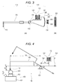
- Fig. 3 is a schematic diagram of the shape measuring machine of the present invention.
- the scale detector 114 is configured mainly including a scale 302 (a scale plate), a scale reading unit 304, and a computing unit (not illustrated).
- the scale 302 is mounted on a distal end surface 300 of the second end 118 of the arm 106. Graduations are continuously formed on the scale 302.
- the distal end surface 300 is preferable to be a curved surface, especially an arc with the fulcrum 104 at the center. M ore specifically, the shape of a cross section of the distal end surface 300, the cross section being parallel to a surface of rotation of the arm 106, is preferable to be an arc with the fulcrum 104 at the center.
- T he distal end surface 300 is an arc with the fulcrum 104 at the center. Accordingly, even if the arm rotates (swings) about the fulcrum 104, the distance between the scale reading unit 304 and the scale 302 is always constant, and the angle of the scale 302 with respect to the scale reading unit 304 is also always constant.
- the scale reading unit 304 can always read the scale on the same condition even if the arm 106 rotates. Hence, the scale reading unit 304 has little influence of external disturbance, can read the scale correctly, and can measure displacement of the arm with high accuracy.
- T he scale 302 can also be formed di rectly on the distal end surface 300.
- the scale 302 be produced by forming graduations on a flexible sheet-shaped member, and the scale 302 be affixed to the distal end surface 300 to form the scale 302 on the distal end surface 300.
- the scale 302 which is a sheet-shaped member with graduations placed with a correct pitch, is affixed to the distal end surface 300 to enable easy formation of the highly accurate scale 302 on the distal end surface 300.
- a flexible member such as a plastic member or metal member can be used as a flexible sheet-shaped member used for the scale 302.
- a flexible sheet-shaped member used for the scale 302.
- aluminum, stainless, PET film, or the like is preferableto be used astheflexiblesheet-shaped member.
- the scale 302 is produced usi ng the flexible sheet-shaped member to be affixed to the distal end surface 300 bei ng a curved surface. Accordingly, the scale 302 having extremely highly accurate graduations can be formed on the curved surface.
- the calibration jig according to the present invention includes a ball gauge and a step gauge.
- Fig. 4 is an explanatory diagram for explaining calibration by the shape measuring machine according to the present invention.
- Fig. 5 is a schematic explanatory diagram of a step gauge being the calibration jig of the present invention.
- Fig. 6 is an explanatory diagram of a computed shape of a ball of the ball gauge (stylus height calibration).
- Fig. 7 is an explanatory diagram of a computed shape of the ball of the ball gauge (arm length calibration).
- a ball gauge 402 being the calibration jig according to the present invention, let the length of the arm 106 (the horizontal length between the fulcrum 104 and the styl us 110) be L a, let the horizontal length between the fulcrum 104 and the displacement sensor 112 be L0, and let the angle of the arm 106 with respect to a horizontal position at the fulcrum 104 upon the swi ng of the arm 106 be q.
- the ball gauge 402 is configured including a block 421, a column 422 standing on a top surface of the block 421, and a ball 423 fixed on the column 422, the ball 423 requiring a diameter and sphericity in advance with high accuracy.
- a step gauge 502 bei ng the calibration jig according to the present invention is configured in such a manner as that a block gauge 532 is attached to a top surface of a reference base 531.
- the top surface of the reference base 531 is placed parallel to an X direction.
- the flatness of the top surface is precisely finished.
- the thickness of the block gauge 532 is known. Consequently, a distance Ho (step dimension) between the top surface of the reference base 531 and a top surface of the block gauge 532 is known.
- the stylus 110 is placed on the surface of the to-be-measured object 108 while bei ng added a predetermined load.
- the stylus 110 moves relatively to the to-be-measured object 108, follows projections and depressions on the surface of the to-be-measured object 108, and repeats up-and-down motion.
- a steppi ng motor or the like may either move the arm 106 or move a seat where the to-be-measured object 108 is placed, in a method for moving the stylus 110 relatively to the to-be-measured object 108.
- the stylus 110 moves up and down to rotate the arm 106 about the fulcrum 104 supported by the support unit 102.
- the support unit 102 is disposed in such a manner as to place the fulcrum 104 at a position further away from the stylus than the center of the arm 106.
- the stylus 110 can easily move up and down with a small force by the principle of leverage regardless of that the displacement sensor 112 and the scale detector 114 are mounted at the second end 118.
- the stylus 110 can reliably follow minute irregularities on the surface of the to-be-measured object 108.
- a ccordi ngly, the shape of the surface of the to-be-measured object 108 can be measured with high accuracy.
- the displacement sensor 112 and the scale detector 114 detect displacement of the arm 106 caused by the rotational motion in synchronization with the up-and-down motion of the stylus 110.
- the core 120 mounted in such a manner as to move in synchronization with the arm 106 moves in the coil 122 in synchronization with the rotation of the arm 106.
- An unillustrated processing unit processes an induced voltage that is generated in the coil when the core 120 moves in the coil 122. Accordingly, a displacement of the arm 106 is obtained. The processing unit further obtains a displacement of the stylus 110 from the displacement of the arm 106. Consequently, the surface shape of the to-be-measured object 108 can be measured.
- a displacement of the arm 106 is normally obtained by a method using these sensors, and a displacement of the stylus 110 is obtained from the displacement of the arm 106.
- These displacement sensors are used to enable highly accurate measurement of the uneven shape of the surface of the to-be-measured object 108.
- the CADICOM (CADICOM) series made by Tokyo Seimitsu Co., Ltd. can be preferably used as the capacitive sensor.
- E-DT-CA21A or the like is simply required to be used as the sensor.
- the response frequency is 4 kHz, which is very high, and measurement at high resolution and high response speed is possible.
- a light emitting unit 306 including an L D (Laser diode) or LED (Light emitting diode) applies light to the scale 302.
- the applied light is reflected by the scale 302, and is received by a light receiving unit 308 including a PD (Photo diode) or the like.
- a signal of the brightness of the received light is converted by the light receiving unit into an electrical signal.
- the unillustrated processing unit obtains a displacement of the arm 106, and further obtai ns a displacement of the stylus 110 from the displacement of the arm 106.
- the displacement sensor 112 has high resolution, but has not-so-good accuracy when displacement is large, and has poor linearity in a wide detection range.
- the scale detector 114 does not have resolution as high as the displacement sensor 112, but maintains the accuracy even if displacement is large, and has good linearity in a wide detection range. In other words, the scale detector can ensure high linearity.
- the processing unit can display, on a display unit (not illustrated), a value measured by the displacement sensor 112 when the detection range or displacement is equal to or less than a predetermined value. Furthermore, the processing unit can display, on the display unit, a value measured by the scale detector 114 when the detection range or displacement exceeds the predetermined value.
- the shape measuring mac hi ne of the present invention includes two detectors: the displacement sensor 112 and the scale detector 114. Accordingly, it is also possible to use one detector to calibrate the other detector and correct the origin.
- the differential transformer or the like has sensitivity that is likely to change, and also has its influence upon calibration.
- K a correction coefficient of a change in sensitivity of the differential transformer or the like.
- a differential transformer sensor or the like is susceptible to changes in temperature. Accordingly, its sensitivity (the inclination of linearity) changes. Consequently, the point of zero (origin) is offset.
- the relative positions of the two sensors are stored.
- the measuring machine is calibrated (daily calibration)
- the deviation amount is detected with reference to the scale resistant to changes in temperature to correct the inclination and offset.
- T he ball gauge 402 illustrated in Fig. 4 and the block gauge 532 illustrated i n Fig. 5 are used to perform calibration as follows:
- the distal end of the stylus 110 has as high sphericity as a ruby ball, and its radius requires correctness, the above method will do. If not, the radi us of the distal end of the stylus 110 is calibrated from the difference of the ball of the ball gauge between the known shape value and the computation shape value after the stylus height Ha and the arm length L a are cal i brated.
- the calibration method is further described using Figs. 4 and 5 .
- the design values of the stylus height Ha, the arm length L a, and the radius of the distal end of the stylus 110 are prepared.
- the ball gauge 402 is then mounted.
- the stylus 110 traces an upper side of the ball 423 to obtain the ball measurement data.
- the prepared design values are used to calculate the computation shape values ( Figs. 6 and 7 ) of the ball 423 from the measurement data.
- Fig. 6 represents the computation shape values of when the arm length La is correct and the stylus height Ha is incorrect.
- Fig. 7 represents the computation shape values of when the stylus height Ha is correct and the arm length La is incorrect.
- the actual computation shape values are a combination of both. They are illustrated, separated for description.
- a difference between a computation shape value MI on the left and a computation shape value Mr on the right is calculated.
- the computation shape val ues are divi ded into the left and the right in the X di recti on with a vertex Mo as a boundary.
- Dl and Dr which are equal in numbers on the right and the left from the vertex Mo
- circles are respectively obtained by the least squares method.
- a difference between the radii of the circles is defined as the difference between the computation shape values.
- the computati on shape val ues represent an elliptical shape inclined obliquely (the example illustrated in Fig.
- the difference between the right and left computation shape values is calculated to determine the difference.
- the stylus height Ha is computed in such a manner to make the difference small.
- the stylus height Ha is temporarily calibrated to the value.
- the difference between the right and left computati on shape values is determined again and confirmed.
- a difference between a computation shape val ue M u on the upper side and a computation shape val ue M d on the lower side is calculated.
- the computation shape values are divided into upper measurement data of an area between the vertex Mo and Du and lower measurement data of an area between Du and Dd (Du and Dd are equal in numbers).
- a circle is obtained by the least squares method for each of the upper and lower measurement data sets. The difference between the radii of the circles is defi ned as the difference of the computation shape values.
- the computation shape values represent an elliptical shape having a long or short axis in the up-and-down direction (an elliptical shape having a long axis in the up-and-down direction in the example illustrated in Fig. 7 ).
- the difference between the upper and lower computed values is calculated to determine the difference.
- the arm length La is computed in such a manner to make the difference small.
- the arm length La is temporarily calibrated to the value.
- the difference between the upper and lower computation shape values is determined again and confirmed.
- the stylus height Ha and the arm length La approach true values.
- the computation shape values of the ball 423 approach the known shape values more correctly.
- the step gauge 502 is set in the shape measuri ng machi ne 100 instead of the ball gauge 402 to be traced by the stylus 110 as illustrated in Fig. 5 .
- a computation step dimension is calculated from the obtained step measurement data.
- the arm length La is calibrated in such a manner as to make the calculated computation step dimension equal to the known step dimension Ho.
- a difference r between a known shape val ue N and a computation shape val ue M of the ball 423 is set as the radius of the distal end of the stylus 110.
- the radius of the distal end of the stylus 110 is cal i brated to the value.
- the difference r between the known shape val ue N and the computation shape val ue M varies depending on the measurement position.
- the stylus can be replaced without cal i brati ng the radi us of the distal end of the stylus.
- a spherical ball gauge is used as a gage for calibration.
- the distal end of the stylus is also spherical.
- the arm has a mechanism to turn around the fulcrum to check the linearity.
- the displacement occurri ng due to the turn is read by the arc scale. In other words, everything is circular motion.
- the displacement of circular motion can be read as an angle.
- the ratio of the length of the first end 116 to the length of the second end 118 is changed to evaluate sensitivity (responsivity) and linearity of the displacement sensor 112 and the scale detector 114.
- a differential transformer sensor is used as the displacement sensor 112.
- Sensitivity (responsivity) in the evaluations indicates trackability of minute displacement, and linearity indicates spatial accuracy in the entire measurement range.
- the sensors used in the present invention require high linearity in a wide measurement range while meeti ng high sensitivity and high responsivity in the trackability of mi nute displacement.
- Measurement of sensitivity was performed by providing minute displacement to a to-be-measured object using a piezoelectric element, and measuring the displacement of the displacement sensor of the detector from the input (displacement) to the piezoelectric element.
- Measurement of linearity was performed by using a laser length measuring machine and a movable stage, moving the stage in a state where the stylus 110 is caused to vertically touch the movable stage, measuri ng the movement amount of the stage with the laser length measuring machine, and measuring a difference from the displacement of the stylus.
- the following table 1 is a table showing the evaluation results. As illustrated in table 1, when the ratio of the length between the fulcrum and the distal end of the first end (the length of the first end) to the length between the fulcrum and the distal end of the second end (the length of the second end) was 1 : 1 - 6 : 1, sensitivity and linearity were both excellent. Moreover, when the range was 2 : 1 - 4 : 1, sensitivity and linearity were most excellent.
- the ratio of the length between the fulcrum and the distal end of the first end (the length of the first end) to the length between the fulcrum and the distal end of the second end (the length of the second end) be 1 : 1 - 6 : 1, and most preferably, 2 : 1 - 4 : 1.
- Fig. 9 is a diagram illustrating the configuration of a shape measuring machine of a second embodiment of the present i nventi on.
- a shape measuring machine 900 of a second embodiment includes a holder 910 rotatably supported by the support unit 102 to engage with a housi ng, the arm 106 to be detachably caught by the holder 910, the stylus 110 provided at a distal end of the arm 106, the displacement sensor 112 (a differential transformer sensor in the second embodiment) that outputs a signal in accordance with the displacement of the holder 910, and the scale detector 114 that outputs a signal in accordance with the displacement of the holder 910.
- the arm 106 provided with the stylus 110 is referred to as a gauge head 920.
- the displacement sensor 112 includes a fixed portion fixed to the housing of the shape measuring machine 900, and including a plurality of coils, and an iron-core portion attached to the holder 910.
- the position of the iron-core portion with respect to the plurality of coils of the fixed portion changes with the rotation of the holder 910.
- the strength of an alternati ng current signal (detection signal) generated in the coil changes.
- the scale detector 114 includes a scale attached to the holder 910 and having a black and white pattern radial ly provided with the support unit 102 at the center, and a detection unit fixed to the housing of the shape measuring machine 900 to read the displacement (rotation amount) of the scale. When the scale rotates with the rotation of the holder 910, the detection unit reads the rotation amount (rotation position).
- An index scale may be used for the detection unit.
- the displacement sensor 112 and the scale detector 114 are widely known. T herefore, they are not described in detail further.
- the differential transformer sensor can detect minute displacement with high resolution.
- the linearity of the differential transformer sensor in a wide detection range is not sufficient.
- the scale sensor can detect displacement with high accuracy in a wide range.
- the scale sensor has difficulty in obtaining as high resolution as the differential transformer sensor.
- the displacement sensor is a high-resolution (high-sensitivity) sensor and a sensor with high responsivity.
- the displacement sensor is not a sensor with high linearity.
- the scale sensor can measure displacement with high accuracy in a wide range, and has high linearity.
- the scale sensor is not a sensor with high resolution and high responsivity.
- a tape scale such as the FAST RACK series made by Renishaw or ERA700 made by HEIDE NHAIN is suitably used as the scale detection mechanism.
- the scale detection mechanism may be a general stainless scale, or arc scale marked on a glass surface.
- the above-mentioned FAST RACK series made by Renishaw is affixed by double-sided tape to the curved portion.
- the scale is consecutively marked with graduations with a pitch of 20 mm.
- some deviation and the like may occur depending on the precision of affixation.
- multiple block gauges with different thicknesses are measured in advance and calibration is performed drawing a correlation straight line. Accordingly, the deviation is checked and corrected.
- the advantage of the use of such a scale is that since the graduations are continuously marked on multiple points at regular intervals, a correction including linearity can be made based on the continuity. From the above point, the scale detector is a high-linearity detector that has high linearity and can correct the linearity.
- the influence of thermal expansion of the scale itself and the like is also conceivable under a severe environment in terms of the temperature condition.
- the scale is thermally expanded due to the environment, it is not considered that part of the scale is locally and thermally expanded, but is generally considered that the entire scale is uniformly and thermally expanded.
- Examples of such a scale sensor also include a laser scale used for laser length measurement.
- T his uses interference of light.
- the laser scale is not a solid scale but can measure a length correctly in a non-contact manner, has high linearity in a long range, and plays the role of a scale.
- DISTAX 300A made by Tokyo Seimitsu Co., Ltd. or the like can measure a length using laser interference.
- the laser scale using laser interference has stable linearity if a medium has a uniform refractive rate in a wide range. Hence, this is a scale with high linearity.
- the influence of the thermal expansion of the scale of the scale detector can be estimated to some extent based on the deviation of the linearity of the differential transformer due to the temperature environment from the scale detector.
- detection signals output from the displacement sensor 112 and the scale detector 114 are processed by an unillustrated signal processing unit.
- the signal processing unit may be provided inside or outside the housing of the shape measuri ng machi ne 900. Furthermore, part of the signal processing unit may be provided inside the housi ng of the shape measuri ng machi ne 900 and the rest outside the housing of the shape measuring machine 900.
- Fig. 10 is a block diagram illustrating the configuration of a portion that performs signal processing in the shape measuri ng machi ne of the second embodi ment, in which (A) illustrates the entire configuration, (B) illustrates the configuration of a scale signal processing unit 1061, and (C) illustrates the configuration of a differential transformer signal processing unit 1062.
- the shape measuring machine of the second embodiment includes the scale signal processing unit 1061 and the differential transformer signal processing unit 1062 as illustrated in Fig. 10(A) .
- the shape measuri ng machi ne conducts measurement while moving the stylus 110 on the surface of a work W at a constant speed.
- the ti me axis of the detection signals output from the displacement sensor 112 and the scale detector 114 corresponds to the distance on the surface of the work W. This is used for processing in the signal processing unit to perform signal processing.
- the scale signal processing unit 1061 processes a detection signal output from the scale detector 114, and generates and outputs first displacement data. For example, as illustrated in FIG. 10(B) , the scale signal processing unit 1061 performs, on a scale signal being the detection signal output from the scale detector 114, an A/D conversion process 1064 that converts the scale signal into a digital signal. Furthermore, a first filtering process 1065 to remove components equal to or less than a wavelength corresponding to a displacement component in a long distance is performed on the digital signal to generate the first displacement data.
- the scale detector 114 converts a change in rotation amount into a change in height.
- the conversion can be basically performed by a conversion equation.
- the scale signal processing unit 1061 stores, as the calibration data, a difference between the detection signal that is output from the scale detector 114 when correct displacement is performed, and the correct displacement. When generating the first displacement data, the scale signal processing unit 1061 also makes corrections for the cal i brati on data.
- Fig. 11 is a diagram explaining the calibration data creation process of the scale signal processing unit 1061.
- the arm 106 rotatably supported by the support unit 102 is provided at one end with the gauge head 920, and at the other end with part of the scale detector 114, to detect a displacement (or the rotation amount) along the arc at the other end of the arm 106.
- Fig. 11(A) is a diagram illustrating a change example of a read value of the detection signal of the scale detector 114 of when the block gauges with different heights are measured.
- the differential transformer signal processing unit 1062 processes a detection signal output from the displacement sensor 112, and generates second displacement data.
- the differential transformer signal processing unit 1062 can perform similar processing to one that is conventionally performed, on the detection signal output from the displacement sensor 112 to output displacement data si mi lar to the conventional one, as the second displacement data.
- the differential transformer signal processing unit 1062 performs, for example, anA/D conversion process 1066 that causes a conversion into a digital signal, on a differential transformer signal being the detection signal output from the displacement sensor 112.
- the differential transformer signal processing unit 1062 further performs, on the digital signal, a second filtering process 1067 that removes distortion, noise, and the like of the stylus 110 to generate the second displacement data.
- the second filtering process 1067 for example, if the radius of the distal end of the stylus 110 is 2 mm, components equal to or less than 2.5 mm are removed.
- displacement is large, the linearity of the detection signal output from the displacement sensor 112 deteriorates.
- the fi rst displacement data and the second displacement data are output as they are.
- the contour shape data indicated by the first displacement data and the surface roughness data indicated by the second displacement data can be simultaneously obtained in one measurement.
- Fig. 12 is a block diagram illustrating the configuration of a portion that performs signal processing and a selection in a shape measuring machine of a third embodiment of the present invention.
- the shape measuring machine of the third embodi ment includes the scale signal processing unit 1061, the differential transformer signal processing unit 1062, and a selection unit 1263 as illustrated in Fig. 12 .
- the scale signal processing unit 1061 and the differential transformer signal processing unit 1062 are the same as those of the first embodi ment.
- T he selection unit 1263 selects and outputs one of the fi rst displacement data output from the scale signal processing unit 1061 and the second displacement data output from the differential transformer signal processing unit 1062, in accordance with a selection signal indicating which of the contour shape and the surface roughness is measured. Specifically, when the contour shape is measured, a signal to select the fi rst displacement data is input as the selection signal. The selection unit 1263 outputs the fi rst displacement data output from the scale signal processing unit 1061 as detection data. Moreover, when the surface roughness is measured, a signal to select the second displacement data is input as the selection signal. The selection unit 1263 outputs the second displacement data output from the differential transformer signal processing unit 1062 as the detection data. For example, a user of the shape measuring machi ne operates a process selection button provided to the apparatus to generate the selection signal.
- the selection unit 1263 selects and outputs one of the first and second displacement data in accordance with the selection signal.
- the selection unit 1263 can also make a selection by another method.
- a selection made by the selection unit 1263 is controlled by another method.
- Fig. 13 is a block diagram illustrating the configuration of a portion that performs signal processing and a selection in a shape measuring machine of the fourth embodiment of the present invention, and a diagram explaining switching of the selection signal.
- the fourth embodiment has a configuration where a selection control unit 1369 is further provided in addition to the configuration of the thi rd embodi ment illustrate in Fig. 12 .
- the selection control unit 1369 receives the first and second displacement data and controls selection in the selection unit 1263.
- Fig. 13(A) describes the selection control unit 1369 receives both the first and second displacement data, but may receive only one of them.
- Fig. 13(B) illustrates a change example of the value of the second displacement data from actual displacement.
- the second displacement data is, for example, within a range between an upper threshold value +Sh and a lower threshold value - Sh
- the value of the second displacement data changes with high linearity (lineally) from the actual displacement.
- linearity deteriorates and the error increases.
- the error can be corrected by calibration.
- the selection control unit 1369 of the third embodiment controls the selection unit 1263 to select the second displacement data if the second displacement data is within the range between the upper and lower threshold values, Sh, in other words, if displacement is within, Th correspondi ng to, Sh, and to select the first displacement data if the second displacement data is out of the range between the upper and lower threshold values, Sh, in other words, if displacement is out of the range of, Th.
- Th can also be determined based on the first displacement data output from the scale signal processing unit 1061.
- a case of such a correction corresponds to a case where a correction is not made with the first displacement data based on the judgment that linearity is ensured.
- Even the differential transformer detection mechanism being the second displacement data is on the precondition that the vicinity of the point of zero is a range that ensures linearity and requires no correction based on the first displacement data. Which area should be set as a correction range depends on the area where the second displacement data is regarded to ensure linearity in prior calibration.
- surface roughness may also be desired to be measured si multaneously.
- the contour shape is conventionally measured and then the surface roughness of the same surface is measured.
- a ccordi ngly the measurement ti me is long.
- the surface roughness data is output. If displacement is out of the range between the upper and lower threshold values, the contour shape data is output.
- the surface roughness data can also be used as the contour shape data.
- the contour shape data can be obtained over the enti re measurement range, and also the surface roughness data can be obtained at the same ti me if displacement is within the range between the upper and lower threshold values.
- Fig. 14 is a diagram illustrating examples of the second displacement data (surface roughness data) and the fi rst displacement data (contour shape data) of a case where displacement changes within a small range.
- Fig. 14(A) illustrates a change example of the second displacement data (surface roughness data).
- Fig. 14(B) enlarges and illustrates changes in the second displacement data (surface roughness data).
- Fig. 14(C) illustrates a change example of the first displacement data (contour shape data).
- Fig. 14(D) enlarges and illustrates changes in the first displacement data (contour shape data).
- the second displacement data (surface roughness data) has high resolution. Accordingly, even if it is enlarged, its change is smooth.
- the second displacement data (surface roughness data) has, for example, a resolution of 1 nm.
- the first displacement data (contour shape data) has lower resolution than the second displacement data. Accordingly, if it is enlarged, its change is stepwise.
- the fi rst displacement data (contour shape data) has, for example, a resolution of 50 nm, and has sufficient resolution as data indicating a contour shape. Hence, there is no problem i n a case of i ndicati ng a contour shape.
- the resolution of the first displacement data is i nsuffi ci ent as data indicating surface roughness.
- the second displacement data is output as the data indicating a contour shape.
- signal processing is performed on both the detection signals output from the scale detector 114 and the displacement sensor 112.
- the detection signals are then converted into the first and second displacement data, both or either of which are selected and output.
- the data to be output is the scale signal and the differential transformer signal.
- the scale signal (thefirst displacement data) and the differential transformer signal (the second displacement data) are signals that have individually different resolutions and sensitivities but are obtained by measuring the same portion of a work. T hey are related to each other. Hence, it is desi red that the scale signal (the first displacement data) and the differential transformer signal (the second displacement data) be mutual ly corrected to generate measurement data suitable to a requirement. In an embodiment described below, such a correction process is performed.
- the scale signal output from the scale detector 114 does not have high resolution, but has high linearity over a wide detection range.
- the differential transformer signal output from the displacement sensor 112 has high resolution but has insufficient linearity in a wide detection range. Therefore, the basic correction process is to create correction data in such a manner as that a long-period component of the differential transformer signal (the second displacement data) agrees with a long-period component of the scale signal (the first displacement data), and to correct the differential transformer signal (the second displacement data) only for the correction data.
- T can be vari ous modifications for the correcti on process.
- F i rstly there are two cases: in one case, correction data generated based on the detection signals output from the displacement sensor 112 and the scale detector 114 is output during movement when the styl us 110 is bei ng moved along the surface of the work W at a constant speed, in other words, is output in real time; in the other case, the correction data is output after the movement of the stylus 110 along the surface of the work W in the measurement range is finished. Firstly, the case of real-time output is described.
- Fig. 15 is a block diagram illustrating the configuration of a portion that performs signal processing in a shape measuring machine of a fifth embodiment, in which (A) illustrates the entire configuration, (B) illustrates the configuration of the differential transformer signal processing unit 1062, and (C) illustrates another configuration of the differential transformer signal processing unit 1062.
- the portion that performs signal processing includes the scale signal processing unit 1061, the differential transformer signal processing unit 1062, and a correction processing unit 1570.
- T he scale signal processing unit 1061 has the configuration illustrated in Fig. 10(B) and, as in the first to fourth embodiments, processes the detection signal output from the scale detector 114, generates the first displacement data, and outputs it to the correction processing unit 1570.
- the fi rst displacement data is used to correct the linearity of the second displacement data output from the differential transformer signal processing unit 1062.
- a correction is made usi ng a displacement component of the scale signal in a long distance, that is, a long-period (long-wavelength) component in terms of distance and ti me.
- a displacement component in a short distance that is, a short-period (short-wavelength) component is not required. Accordingly, components equal to or less than a predetermined wavelength are removed.
- the differential transformer signal processing unit 1062 processes the detection signal output from the displacement sensor 112, generates the second displacement data, and outputs it to the correction processing unit 1570.
- the differential transformer signal processing unit 1062 has the configuration illustrated in Fig. 10(C) .
- the differential transformer signal processing unit 1062 can perform a similar process to one that is conventionally performed, on the detection signal output from the displacement sensor 112 and output displacement data similar to the conventional one as the second displacement data.
- linearity is corrected based on the fi rst displacement data output from the scale signal processing unit 1061, in other words, a long-period (long-wavelength) component is corrected. Therefore, the second displacement data is not required.
- the long-period (long-wavelength) component is desired to be removed.
- the differential transformer signal processing unit 1062 performs theA/D conversion process 1066 that causes a conversion into a digital signal, on the differential transformer signal being the detection signal output from the displacement sensor 112.
- the differential transformer signal processing unit 1062 further performs, on the digital signal, the second filtering process 1067 that removes distortion, noise, and the like of the stylus 110.
- the differential transformer signal processing unit 1062 then performs a third filtering process 1568 that removes components equal to or more than a wavelength corresponding to an interval between correction poi nts to generate the second displacement data.
- the second filtering process 1067 is, for example, the same process as that of Fig. 10(C) .
- the differential transformer signal processing unit 1062 performs a bandpass filtering process.
- a short-wavelength component may be removed from the differential transformer signal in like manner with the scale signal to generate the correction data.
- theA/D conversion process 1066 that causes a conversion into a digital signal is performed on the differential transformer signal.
- the first filtering process 1065 is performed on the digital signal.
- a process of generating data for correction is separately performed.
- the correction processing unit 1570 corrects a long-period component of the second displacement data in such a manner as to match the first displacement data.
- Fig. 16 is a diagram explaining signal processing and the correction process in the fifth embodi ment.
- Fig. 16(A) illustrates the scale signal output from the scale detector 114, or a digital signal obtained by A/D converting the scale signal.
- the first filtering process 1065 is performed on the signal to obtain the fi rst displacement data where a short-wavelength component has been removed as illustrated in Fig. 16(B) .
- Fig. 16(C) illustrates the differential transformer signal output from the displacement sensor 112, or a digital signal obtained by A/D converting the differential transformer signal.
- the second filtering process 1067 and the third filtering process 1568 are performed on the signal to obtain the second displacement data where only an intermediate-wavelength component is left and the other short-wavelength and long-wavelength components have been removed as illustrated in Fig. 16(D) .
- the correction processing unit 1570 makes corrections in such a manner as to agree in displacement of the long wavelength between the first displacement data of Fig. 16(B) and the second displacement data of Fig. 16(D) . Specifically, a correction is made to agree in height and inclination between the first displacement data of Fig. 16(B) and the second displacement data of Fig. 16(D) at each point.
- the corrections may be continuously made. Alternatively, discrete corrections may be made in such a manner as that val ues of correction poi nts (indicated by bl ack dots) of the second displacement data in Fig. 16(D) match values of correction points in Fig. 16(B) . Consequently, corrected displacement data illustrated in Fig. 16(E) is obtained.
- the correction it is required to obtain long-wavelength components of the scale signal and the differential transformer signal. Hence, a later displacement signal at the correction positi on is also requi red to be sampled to some extent. Furthermore, a computing process requires a little time. Hence, the correction data is real time, but is output with some ti me delay.
- the long-wavelength component is generated by the filtering process on the scale signal. It is also possible to generate the contour shape data where steps have been removed by a moving average of displacement data obtained by A/D converting the scale signal, a least squares line or spline of previous data on the predetermined number of samples, or the like.
- Fig. 17 is a diagram further explaining signal processing and the correction process.
- the diagrams are diagrams that give a description taking, as an example, a case where fi rst correction data (the scale signal) si mply increases such as a case where a gradually inclined flat surface is measured.
- the value of the first displacement data increases linearly.
- Fig. 17(B) in terms of the differential transformer signal before the third filtering process 1568 is performed, its average value agrees with the first displacement data near the middle point, but has a smaller value than the first variation data in regions on both sides.
- Fig. 15(C) when the first filtering process is performed on the differential transformer signal, then the change of the average value illustrated in Fig. 17(B) is obtained.
- W hen a difference between the val ue obtained by performing the fi rst filtering process on the differential transformer signal, and the fi rst displacement data is calculated, the result is a change indicated byA in Fig. 17(C) .
- correction data indicated by B is obtained.
- the correction data is added to the second displacement data to obtain corrected displacement data illustrated in Fig. 17(D) .
- Fig. 18 and Fig. 19 are diagrams illustrating specific measurement examples in the fifth embodi ment.
- he work W targeted for measurement has a flat surface, and has roughness to some extent, as illustrated in Fig. 18(A).
- Fig. 18(B) illustrates the differential transformer signal or second displacement data measured in a state of holding the work W horizontally.
- Fig. 18(C) illustrates the scale signal or first displacement data measured in a state of hol i ng the work W horizontal ly.
- Fig. 18(D) illustrates a state of inclining and holding the work W.
- Fig. 18(E) illustrates the differential transformer signal or second displacement data measured in a state of inclining and holding the work W.
- Fig. 18(F) illustrates the scale signal orfirst displacement data measured in a state of inclining and holding the work W.
- a least squares line S0 of the second displacement data related to the measurement of the work W held horizontally agrees with a reference line indicating the zero level.
- a least squares line S1 of the first di spl acement data related to the measurement of the work W held horizontally also agrees with the reference line.
- a least squares line S2 of the second displacement data related to the measurement of the work W inclined and held has an angle corresponding to the angle of inclination with respect to the reference line but is not a perfect straight line.
- a least squares line S 3 of the first displacement data related to the measurement of the work W inclined and held is a straight line having an angle corresponding to the angle of inclination with respect to the reference line.
- the correction processing unit 1570 generates correction data in such a manner as that the least squares line S2 of Fig. 18(E) agrees with the least squares line S3 of Fig. 18(F) .
- the fi rst di spl acement data corrected by the correction data is as illustrated in Fig. 19 . Consequently, a surface roughness signal having high linearity in a wide range is obtained.
- the scale signal is read at intervals of a constant pitch, and inclination of each pitch is obtained. Furthermore, the differential transformer signal is divided by the pitch interval. Multiply by a coefficient in order that an average inclination between pitches of the differential transformer signal agrees with the inclination of each pitch of the scale signal.
- the average inclination between pitches of the differential transformer signal is calculated by, for example, a least squares line or spline.
- the two pi eces of data are superi mposed in such a manner as that end poi nts between pitches agree with each other to calculate the corrected displacement data.
- a difference in long-wavelength component between the displacement sensor 112 and the scale detection mechanism is measured in advance.
- the difference measured by the correction processing unit 1570 is stored as the correction data.
- the correction data is added to the second displacement data output from the differential transformer signal processing unit 1062 to generate the corrected displacement data.
- the measurement of the difference i n long-wavelength component between the displacement sensor 112 and the scale detection mechanism is desi red to be conducted at any ti me to update the correction data.
- the method for generating correction data continuously and the method for generating correction data discretely can be applied to the measurement of the difference in long-wavelength component between the displacement sensor 112 and the scale detection mechanism.
- the measurement does not need to be conducted in real ti me.
- the difference i n long-wavelength component between the displacement sensor 112 and the scale detection mechanism may be calculated based on data of the previous measurement to update the correction data.
- measurement data over the enti re detection range needs to be stored.
- an inclined surface of a work with excellent straightness is measured in advance to generate the scale signal and the differential transformer signal, which are illustrated in Figs. 15(A) and 15(B) .
- a process of leaving only the long-wavelength component is performed on both of them.
- a difference between the two pieces of data is calculated.
- a polynomial that approxi mates the difference for the val ue of the differential transformer signal is calculated based on the calculated difference, and stored.
- a Iternatively, a lookup table where the difference is mapped for the value of the differential transformer signal is created and stored.
- the stored polynomial is used for the value of the differential transformer signal to calculate the difference.
- the difference stored in the lookup table for the value of the differential transformer signal is read.
- the difference is added to the value of the differential transformer signal to calculate the corrected displacement data.
- the corrected displacement data is not generated in real time, but is generated after the movement of the stylus 110 over the enti re measurement range is finished, a similar process to the above process can be applied. There is sufficient time for processing. A ccordi ngly, a more highly accurate process can be performed.
- the scale signal is simply required to be able to detect displacement at the correction point with high accuracy.
- a black and white pattern does not need to exist continuously, but is simply required to exist correspondi ng to the correcti on poi nts.
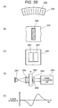
- Fig. 20 is a diagram illustrating an example of an optical scale detection mechanism that detects displacement discretely with high accuracy.
- a plurality of black lines 2082 is radially formed, spaced on a scale 2081 with the support unit 102 at the center.
- Fig. 20(B) is a diagram illustrating one black line 2082 and its vicinity is transparent.
- Fig. 20(C) illustrates a light receiving device 2085.
- the light receiving device 2085 is a two-segment light receiving device, and includes two light receiving units 2086 and 2087 that have the same shape and the same characteristics.
- a detection unit is provided in such a manner as to sandwich the scale 2081.
- the detection unit includes a light source 2091, a lens 2092 that makes light from the light source 2091 parallel, the light receiving device 2085 provided close to a side, where the black lines 2082 are formed, of the scale 2081, and a signal processing unit 2090 that processes a signal of the light receiving device 2085.
- the signal processing unit 2090 includes an analog circuit. The analog circuit computes a difference between output signals of the two light receiving units 2086 and 2087 of the light receiving device 2085.
- the positions of the displacement sensor 112 and the scale detector 114 with respect to the holder 910 and the gauge head 920 can be freely set.
- the displacement sensor 112 and the scale detector 114 are provided opposite to the gauge head 920 with respect to the support unit 102.
- the displacement sensor 112 can also be provided on the same side as the gauge head 920. Consequently, the turning moments of the two sensors on the support unit 102 can be reduced.
- a ccordi ngly the mass for causi ng the gauge head 920 to have a specified measurement pressure can be reduced. As a result, the mass of a swi ng unit rotatably supported at a fulcrum is reduced to enable an improvement in responsivity.
- the shape measuring instrument of the present invention can also be used as a shape measurement/calibration apparatus descri bed below.
- the shape measurement/calibration apparatus is a calibration apparatus for contour shape measurement that measures a contour shape, and can also measure the shape of a to-be-measured object. This is described with reference to the drawings.
- the shape measurement/calibration apparatus is configured mainly including an arc-shaped or spherical calibration jig 200, the stylus 110 that comes into contact with a surface of the calibration jig 200, a feed mechanism (not illustrated) that slides the calibration jig 200 rel atively to the stylus 100, the arm 106 that has the stylus 100 at one end, conveys the displacement of the stylus 110, and rotates about the fulcrum 104, and the scale detector 114, at least part of which is mounted on the arm 106.
- the shape measurement/calibration apparatus can also be configured by including the calibration jig 200 in the embodi ment of the present invention illustrated in Fig. 1 .
- Fig. 23 (explanatory diagram for explaining methods for measuri ng a surface shape of a to-be-measured object and correcti ng the measurement data).
- a n upper diagram in Fig. 23(a) is a diagram representing a state where the stylus 110 traces over the surface of the to-be-measured object 108.
- a dotted line indicated by a symbol 232 indicates a track of the center of a spherical portion 230 at the distal end of the stylus 110.
- the stylus 110 moves in the horizontal direction while in contact with the surface of the to-be-measured object. Accordingly, the shape measuring apparatus captures, as data, the track 232 of the center of the spherical portion 230 of the stylus 110.
- the spherical portion 230 is preferably a shape close to a sphere, and is formed in such a manner as to become closer to a sphere. In the spherical portion 230, only a portion exposed to a surface that comes into contact with the to-be-measured object 108 is required to be a shape close to a sphere.
- the track 232 is a track of the center of the spherical portion 230 and accordingly is located a distance equal to a radius r of the spherical portion 230 away from the surface of the to-be-measured object.
- the shape measuri ng apparatus makes a correction only for the distance equal to the radius r.
- the correction method is to set, as the surface shape of the to-be-measured object, poi nts located after movi ng the poi nts of the track 232 by the distancer in the di rections of the normals to tangents of the poi nts.
- a spherical portion 230a in new condition wears away from use and accordingly changes to a worn-away spherical portion 230b deviating from the spherical shape.
- the radius of the spherical portion 230b becomes uneven. Errors due to variations of the radius are caused upon correction.
- the spherical portion 230 has some deviation from a sphere and accordingly has errors caused by the variations of the radius r.
- Fig. 24 is a diagram illustrating a difference in distance between a spherical portion center C and a contact point in accordance with the shape of the spherical portion 230.
- (a) illustrates a case where the spherical portion 230 has a vertically long elliptical shape
- (b) illustrates a case where the spherical portion 230 is a perfect circle
- (c) illustrates a case where the spherical portion 230 has a horizontally long elliptical shape.
- the distance (the radius r) between the center C and the contact point decreases as the contact position with the to-be-measured object 108 approaches the side of the spherical portion 230.
- the distance (the radius r) between the center C and the contact poi nt gradually increases as the contact position with the to-be-measured object 108 approaches the side of the spherical portion 230.
- the distance (the radius r) between the contact point and the center C is constant even if any part of the spherical portion 230 comes into contact with the to-be-measured object 108.
- the present inventors and the like found the cause of the occurrence of an error due to a change in shape of the spherical portion 230 at the distal end of the stylus 110 as a result of a diligent study and further, invented a method for reducing the error.
- the method for reducing the error is described below.
- Fig. 25 is a diagram illustrating an angle formed by the spherical calibration jig 200 and the stylus 110 having the spherical portion 230 in contact with the calibration jig 200. As illustrated in the figure, q 1 to q 3 represent the angles indicated below:
- the shape measuring apparatus measures the shape of the surface of the calibration jig 200 forming a sphere as illustrated in Figs. 22 and 25 .
- the measurement is conducted by bringing the spherical portion 230 at the distal end of the stylus 110 into contact with the surface of the calibration jig 200, and moving the stylus 110 and the calibration jig 200 relatively to the horizontal direction.
- the shape measuring apparatus associates and stores a horizontal travel distance x, vertical displacement of the stylus 110, and the value of the rotation angle q 3 of the arm caused by the vertical movement of the stylus 110 ( Fig. 22 ).
- the track 232 illustrated in Fig. 23 is obtained from the horizontal travel distance x and the vertical displacement of the stylus 110.
- the direction of the normal to a tangent at each point of the track 232 is obtained to obtain q 1 being the angle formed by the direction of the normal and the vertical direction.
- Fig. 26 is a graph illustrating the relation ship between the movement amount of the calibration jig (a relative movement amount between the calibration jig and the stylus 110) and q 1 .
- Fig. 27 is a graph illustrating the relationship between the movement amount of the calibration jig (a relative movement amount between the calibration jig and the stylus 110) and q 3 .
- Both Figs. 26 and 27 describe, as previously known data, data measured using the distal end portion 230 of which cross section is a perfect circle (described as the perfect circle data), data measured using the distal end portion 230 of which cross section is a vertically long ellipse (described as the vertically long ellipse data), and data measured using the distal end portion 230 of which cross section is a horizontally long ellipse (described as the horizontally long ellipse data).
- T he cross section referred to above indicates a cross section of the distal end portion 230 cut along the surface of rotation of the arm 106.
- These sets of data are known data obtained using those with known shapes of a perfect circle, a vertically long ellipse, and a horizontally long ellipse.
- the results of measurements of a spherical calibration jig of a known size using the shape measuring apparatus targeted for calibration (or the stylus 110 targeted for calibration) are illustrated as the calibration data.
- the calibration data measured this time is located between the perfect circle data and the horizontally long ellipse data. This is illustrated as an example. In reality, the positi on of data changes depending on the shape of the spherical portion 230 at the distal end of the calibration target stylus 110.
- Fig. 28 (a graph illustrating the movement amount of the calibration jig and the radi us of the spherical porti on 230). It can be seen from the graphs obtained in Figs. 26 and 27 , the shape of the spherical portion 230 targeted for calibration is between the perfect circle and the horizontally long ellipse. Consequently, the radius r of the distal end of the spherical portion 230 targeted for calibration should be between the horizontally long ellipse data and the perfect circle data. Therefore, in Fig. 28 , a curve is drawn as the calibration data between the horizontally long ellipse data and the perfect circle data.
- the curve may be drawn in such a manner as to be placed in the middle between the horizontally long ellipse data and the perfect circle data.
- what percent the calibration data is closer to which of the perfect data and the horizontally long data may be obtained from the data in Figs. 26 and 27 to draw a curve placing it to one side in accordance with the ratio.
- Figs. 26 to 28 describe only three types of known data. The number of types of known data is increased; accordingly, it is possible to check between which sets of known data the calibration data is located, and obtain the position of a curve of the calibration data in Fig. 28 based on the result. Hence, it is possible to draw a curve of the cal i brati on data more correctly, and esti mate the radi us of the spherical porti on 230 targeted for calibration more correctly.
- T his is described with reference to Fig. 23 .
- the to-be-measured object is measured to obtain the track 232 of the center of the spherical portion 230 ( Fig. 23(a) ).
- the di recti on of the normal to a tangent of the point is obtained.
- q 1 is obtained from the direction of the normal.
- q 3 is obtained from the angle of the arm 106 at the ti me of the measurement of the poi nt.
- q 2 can be obtained from q 1 and q 3 .
- the radius r of the distal end of the spherical portion 230 is obtained at corresponding q 2 from the data obtained by converting the horizontal axis to q 2 .
- the position of the point that has been moved a distance equal to r in the direction of the normal from the measurement point is obtained. This is performed for all the poi nts of the track 232 to set them as the surface shape of the to-be-measured object. Accordingly, it is possible to obtain a highly accurate surface shape of the to-be-measured object where variations of the radius of the distal end of the spherical portion 230 has been corrected.
Abstract
Description
- The present invention relates to a shape measuri ng machi ne for measuri ng the shape of a to-be-measured object, and particularly relates to a shape measuring machine that can measure both a contour shape and surface roughness.
- Surface shape measuri ng machines are conventionally used to measure the surface shape of a to-be-measured obj ect. T here are two types of surface shape measuri ng machines including: a contact type that measures the surface shape of a to-be-measured object in contact with the to-be-measured object; and a non-contact type that measures the surface shape of a to-be-measured object in no-contact with the to-be-measured object.
- Examples of the contact type include one that brings a stylus attached to an arm that swings into contact with a surface of a to-be-measured object and measures movements of the arm made by the stylus moving up and down along projections and depressions to measure the uneven shape of the surface of the to-be-measured object.
- A displacement sensor that can detect mi nute movements of the arm with high accuracy is used to measure minute irregularities in a minute area on the surface of the to-be-measured object. Examples of the displacement sensor include a differential transformer type that electrically detects a change in insertion amount of a core inserted into a coi I, a capacitive type that detects a change in capacitance in accordance with the movement of a probe, and an eddy-current type that detects a change in impedance caused by an eddy current generated in a target object when bringing a coil producing a high-frequency magnetic field close to the target object.
- Such displacement sensors are suitable to measure minute irregularities in a minute area with high accuracy. However, such displacement sensors have poor linearity in a wide detection range; accordingly, the displacement sensors are not suitable to measure the enti re shape of a relatively large area.
- Hence, scale detectors and the like are used to measure the entire shape of a relatively large area of a to-be-measured object. The scale detector includes a scale with graduations, and electrical, magnetic, or optical means for reading the graduation. The scale detectors are suitable to measure the entire shape of a relatively large area. However, the scale detectors have difficulty in measuring minute irregularities with high accuracy.
- Hence, a shape measuring machine disclosed in
Patent Literature 1 includes both a displacement sensor and a scale detector to be able to measure mi nute irregularities in a mi nute area with high accuracy and also measure the enti re shape of a relatively large area. - The shape measuring machine disclosed in
Patent Literature 1 includes a support provided in such a manner as to be movable up and down with respect to a fixed portion, a lever pivotally and swingably supported by the support, and provided at one end with a stylus and a digital detector, and at the other end with an analog detector, and a servo mechanism that moves the support up and down in accordance with output from the analog detector. Consequently, wide-range measurement can be conducted. - T he "support" in
Patent Literature 1 corresponds to a "support unit" in the present invention, the "lever" to an "arm" in the present invention, the analog detector to a displacement sensor in the present invention, and the digital detector to a scale detector in the present invention. - Patent Literature 1:
JP-B-4-1850 - However, the known shape measuring machine described in
Patent Literature 1 is equipped with a digital scale near the stylus on the arm. Hence, the weight of the digital scale is added to the stylus; accordingly, the stylus has not good trackability of irregularities. - Moreover, in the known shape measuring machine described in
Patent Literature 1, the support is moved up and down by the servo mechanism; accordingly, the apparatus becomes complicated and its cost is high. - Moreover, in
Patent Literature 1, the analog detector (a differential transformer type displacement measuring mechanism) detects a displacement of the arm having the stylus at one end. However, its detection signal is used for a servo signal for moving the support of the arm up and down to make the contact pressure of the stylus on a work surface constant. The analog detector does not measure the stylus's displacement itself. Moreover, the digital detector including the digital scale (a scale type displacement measuring mechanism) detects a displacement of the stylus and does not detect a displacement of the arm. In this manner,Patent Literature 1 does not disclose simultaneous measurements of a displacement of a gauge head by measuring a displacement of the arm with both the differential transformer type displacement measuring mechanism and the scale type displacement measuring mechanism. - Hence, this is not for measuring a contour shape accurately and correctly in a wide measurement range and also measuring a minutely uneven shape with high responsivity and high resolution.
- Considering the above circumstances, the present invention is to provide a shape measuring machine that can measure both a contour shape of a wide measurement range and a minutely uneven shape, allows a stylus to have excellent trackability of minute irregularities, and can keep the cost low.
- The probl em of the present i nventi on can be solved by the following i nventi on.
- In other words, a shape measuri ng machi ne of the present invention is a shape measuri ng machi ne that measures the contour shape of a surface of a to-be-measured obj ect and surface roughness, and has main features in including an arm configured to rotate with a support unit as a fulcrum, and a stylus configured to be brought into contact with the to-be-measured object, be displaced up and down following the surface shape of the to-be-measured object, and be mounted at one end of the arm, and, further including, in the arm, a displacement sensor and a scale detector to detect the displacement of the arm caused by the swing.
- Consequently, neither the displacement sensor nor the scale detector is mounted at one end where the stylus is mounted, out of both ends of the arm. Hence, their weights are not added to the stylus, and the stylus has improved trackability of irregularities.
- Moreover, it is possible to obtain a measurement result in a wide range with highly accurate linearity while the displacement sensor picks up information on fine roughness with high sensitivity and high responsivity.
- Moreover, the shape measuri ng machine of the present invention has a main feature in that the displacement sensor is a differential transformer sensor, capacitive sensor, or eddy-current sensor.
- Consequently, minute irregularities on the surface of the to-be-measured object can be measured with high accuracy.
- Furthermore, the shape measuring machine of the present invention has main features in that the stylus is mounted at a fi rst end bei ng the one end of the arm, the displacement sensor and at least part of the scale detector are mounted at a second end bei ng the other end of the arm, the support unit is mounted on the arm to be closer to the second end than the center of the arm, and the ratio of the length between the fulcrum of the arm and a distal end on the first end side to the length between the fulcrum and a distal end on the second end side is 1 : 1 - 6 : 1.
- Furthermore, the shape measuring machine of the present invention has main features in that the scale detector has an arc-shaped scale, and the arc-shaped scale is a flexible linear scale affixed to a curved surface of an arc-shaped housing.
- Consequently, although it is difficult to form graduations with a correct pitch directly on the curved surface, it is easy to form graduations with a correct pitch on a flat sheet-shaped member. Accordingly, a highly accurate scale can be easily formed.
- Moreover, the curved surface of the housi ng has a main feature in that the shape of a cross section parallel to a surface of rotation of the arm is an arc with the fulcrum at the center.
- Consequently, even if the arm rotates about the fulcrum, the distance between a scale reading unit and the scale is always constant. In addition, the angle of the scale with respect to the scale reading unit is also always constant. Hence, the scale can always be read on the same condition. Hence, there is little influence of external disturbance. Accordingly, the scale can be read correctly, and the displacement of the arm can be measured with high accuracy.
- Furthermore, the shape measuring machine of the present invention has a main feature in further including a hemispherical calibration jig of which shape and dimension are known, for calibrating at least one of the displacement sensor and the scale detector.
- Both a contour shape of a wide measurement range and a minutely uneven shape can be measured. The stylus has excellent trackability of minute irregularities. The cost of the shape measuring machine can be kept low.
-
-
Fig. 1 is a conceptual diagram illustrating the configuration of a shape measuri ng machi ne of the present invention. -
Fig. 2 is a conceptual diagram illustrating a measurement state with a stylus facing upward. -
Fig. 3 is a schematic diagram of the shape measuring machine of the present invention. -
Fig. 4 is an explanatory diagram for explaining calibration by the shape measuri ng machi ne accordi ng to the present invention. -
Fig. 5 is a schematic explanatory diagram of a step gauge being a calibration jig of the present invention. -
Fig. 6 is an explanatory diagram of a computed shape of a ball of a ball gauge (stylus height calibration). -
Fig. 7 is an explanatory diagram of a computed shape of the ball of the ball gauge (arm length calibration). -
Fig. 8 is an explanatory diagram of calibration of the radius of a distal end of the stylus. -
Fig. 9 is a diagram illustrating the configuration of a shape measuring machine of a second embodiment of the present i nventi on. -
Fig. 10 is a block diagram illustrating the configuration of a portion that performs signal processing in the shape measuri ng machi ne of the second embodi ment of the present invention. -
Fig. 11 is a diagram explaining a calibration data creation process of a scalesignal processing unit 1061. -
Fig. 12 is a block diagram illustrating the configuration of a portion that performs signal processing and a selection in a shape measuring machine of a third embodiment of the present invention. -
Fig. 13 is a block diagram illustrating the configuration of a portion that performs signal processing and a selection in a shape measuring machine of a fourth embodiment of the present invention, and a diagram explaining switching of a selection signal. -
Fig. 14 is a diagram illustrating examples of second displacement data (surface roughness data) and first displacement data (contour shape data) of a case where displacement changes within a small range. -
Fig. 15 is a block diagram illustrating the configuration of a portion that performs signal processing in a shape measuring machine of a fifth embodiment. -
Fig. 16 is a diagram explaining signal processing and a correction process in the fifth embodi ment. -
Fig. 17 is a diagram further explaining signal processing and the correction process. -
Fig. 18 is a diagram illustrating specific measurement examples in the fifth embodi ment. -
Fig. 19 is a diagram illustrating a specific measurement example in the fifth embodi ment. -
Fig. 20 is a diagram illustrating examples of an optical scale detection mechanism that detects displacement discretely with high accuracy. -
Fig. 21 is a schematic diagram of a shape measuring machine where a displacement sensor is provided on the same side as a gauge head. -
Fig. 22 is a conceptual diagram of a shape measurement/calibration apparatus accordi ng to the present invention. -
Fig. 23 is an explanatory diagram for explaining methods for measuring a surface shape of a to-be-measured object and correcting the measurement data. -
Fig. 24 is an explanatory diagram illustrating a difference in distance between a spherical portion center and a contact point in accordance with the shape of a spherical porti on. -
Fig. 25 is an explanatory diagram illustrating an angle formed by a spherical calibration jig and the stylus having the spherical porti on in contact with the cal i brati on jig. -
Fig. 26 is a graph illustrating the relationship between the movement amount of the calibration jig and q1. -
Fig. 27 is a graph illustrating the relationship between the movement amount of the calibration jig and q3. -
Fig. 28 is a graph illustrating the relationship between the movement amount of the calibration jig and a radi us r of the spherical porti on. - Modes for carrying out the present invention are described in detail hereinafter with reference to the accompanying drawings. Here, portions indicated by the same symbol in the drawings are similar elements having a similar function. Moreover, i n the present invention, when the range of values is expressed using "-", both boundary values are included in the range.
- A first embodiment of a shape measuring machine of the present invention is descri bed with reference to the drawings.
Fig. 1 is a conceptual diagram illustrating the configuration of the shape measuring machine of the present invention. As illustrated inFig. 1 , ashape measuring machine 100 of the present invention mainly includes anarm 106 that swings with asupport unit 102 as afulcrum 104, astylus 110 that comes into contact with a to-be-measured object 108, and is displaced up and down following the surface shape of the to-be-measured object 108, adisplacement sensor 112 for detecting the displacement of thearm 106 caused by the swing, and ascale detector 114. - The
stylus 110 is mounted at a f irst end 116 bei ng one end of thearm 106. Thedisplacement sensor 112 and at least part of thescale detector 114 are mounted at asecond end 118 being the other end of thearm 104. Thesupport unit 102 is mounted on thearm 106, closer to thesecond end 118 than the center. In other words, the first end 116 is configured to be longer than thesecond end 118. - The
displacement sensor 112 is a sensor for detecting with high accuracy mi nute movements of thearm 106 that swings in synchronization with the up-and-down motion of thestylus 110. A ny sensor can be adopted as thedisplacement sensor 112 as long as it can measure mi nute displacement of thearm 106. A differential transformer sensor, capacitive sensor, or eddy-current sensor can be suitably used as thedisplacement sensor 112. Especially, a differential transformer sensor that can measure minute displacement with high accuracy is preferred. - The
scale detector 114 is a detector that reads graduations formed on a scale by an electrical, magnetic, or optical method to read the movement of thearm 106. T here are various types and any type can be adopted also for thescale detector 114. A detector of a type that reads by an optical method is preferred. This is because the type that reads by the optical method is highly accurate, and is not influenced by a surrounding electric field and magnetic field. - In terms of the
displacement sensor 112, the enti re sensor may be mounted on thearm 106, but normally part of it is mounted on thearm 106. For example, the diagram of thedisplacement sensor 112 illustrated inFig. 1 illustrates a differential transformer sensor. As illustrated in the figure, acore 120 is mounted on thearm 106. A coil (or transformer) 122 is not mounted on thearm 106. - Moreover, for example, when an eddy-current sensor is used, main portions such as a coil are mounted outside, and only a detection unit that can produce an eddy current may be mounted on the
arm 106. - Hence, in the present invention, the
displacement sensor 112 includes, as a part of thedisplacement sensor 112, not only parts constituti ng the senor but also portions to be detected. At least part of thedisplacement sensor 112 including the portions to be detected is mounted at thesecond end 118 of thearm 106. - Also in terms of the
scale detector 114, at least part of thescale detector 114 including portions to be detected is mounted at thesecond end 118 of thearm 106 as in thedisplacement sensor 112. - In this manner, both the
displacement sensor 112 that can measure minute displacement and thescale detector 114 that can correctly measure the enti re shape of a large area are included. Hence, both minute irregularities on the to-be-measured object 108 and the entire contour of a wide range can be measured. - Moreover, neither the
displacement sensor 112 nor thescale detector 114 is mounted at thefi rst end 116 where thestylus 110 is mounted. Hence, their weights are not added to the stylus. Hence, the moment of inertia of thefi rst end 116 is reduced. Accordingly, thestylus 110 can have excellent trackability of minute irregularities. - Furthermore, the
support unit 102 is mounted on the arm, closer to the second end than the center. In other words, the shape measuri ng machi ne of the present invention is configured in such a manner as that the length between thefulcrum 104 and a distal end of thefi rst end 116 is made longer than the length between thefulcrum 104 and a distal end of thesecond end 118. - Consequently, it becomes possi bl e for the
stylus 110 to move up and down even with a small force by the principle of leverage. Hence, thestylus 110 can easily follow mi nute irregularities on the surface of the to-be-measured object 108. Accordingly, the uneven shape can be measured with high accuracy. - Moreover, neither the
displacement sensor 112 nor thescale detector 114 is mounted at thefi rst end 116 where thestylus 110 is mounted. Hence, as illustrated i nFig. 2 (Fig. 2 is a conceptual diagram illustrating a measurement state with thestylus 110 faci ng upward), thestylus 110 is caused to face upward to permit measurement on the surface of the to-be-measured object 108 located above thestylus 110. - At this poi nt i n ti me, measurement of the to-
be-measured object 108 located above becomes possi bl e si mply by causi ng thestylus 110 to face upward and applyi ng a little upward force to thestylus 110. Consequently, a measurement target of which measurement target surface faces downward can also be easily measured. - Furthermore, neither the
displacement sensor 112 nor thescale detector 114 is mounted at thefirst end 116 where thestylus 110 is mounted, and thefi rst end 116 is configured to be longer than thesecond end 118. Hence, for example, the stylus can be inserted deep inside a to-be-measured object and conduct measurement as in the measurement of the shape of a cylindrical internal wall. - In this manner, the shape measuring machine of the present invention can conduct measurement even if a measurement target surface is located at a position where it is difficult to conduct measurement with a known apparatus.
- Next, one embodi ment of the scale detector included in the shape measuri ng machine of the present invention is described with reference to the drawings.
Fig. 3 is a schematic diagram of the shape measuring machine of the present invention. As illustrated inFig. 3(A) , thescale detector 114 is configured mainly including a scale 302 (a scale plate), ascale reading unit 304, and a computing unit (not illustrated). - The
scale 302 is mounted on adistal end surface 300 of thesecond end 118 of thearm 106. Graduations are continuously formed on thescale 302. Thedistal end surface 300 is preferable to be a curved surface, especially an arc with thefulcrum 104 at the center. M ore specifically, the shape of a cross section of thedistal end surface 300, the cross section being parallel to a surface of rotation of thearm 106, is preferable to be an arc with thefulcrum 104 at the center. - T he
distal end surface 300 is an arc with thefulcrum 104 at the center. Accordingly, even if the arm rotates (swings) about thefulcrum 104, the distance between thescale reading unit 304 and thescale 302 is always constant, and the angle of thescale 302 with respect to thescale reading unit 304 is also always constant. - Hence, the
scale reading unit 304 can always read the scale on the same condition even if thearm 106 rotates. Hence, thescale reading unit 304 has little influence of external disturbance, can read the scale correctly, and can measure displacement of the arm with high accuracy. - T he scale 302 can also be formed di rectly on the
distal end surface 300. Alternatively, as illustrated inFig. 3(B) , it is preferable that thescale 302 be produced by forming graduations on a flexible sheet-shaped member, and thescale 302 be affixed to thedistal end surface 300 to form thescale 302 on thedistal end surface 300. - It is difficult to form graduations with a correct pitch directly on a curved surface. On the other hand, it is easy to form graduations with a correct pitch on a sheet-shaped member being a flat surface. Hence, the
scale 302, which is a sheet-shaped member with graduations placed with a correct pitch, is affixed to thedistal end surface 300 to enable easy formation of the highlyaccurate scale 302 on thedistal end surface 300. - Here, a flexible member such as a plastic member or metal member can be used as a flexible sheet-shaped member used for the
scale 302. Especially, aluminum, stainless, PET film, or the like is preferableto be used astheflexiblesheet-shaped member. - In this manner, the
scale 302 is produced usi ng the flexible sheet-shaped member to be affixed to thedistal end surface 300 bei ng a curved surface. Accordingly, thescale 302 having extremely highly accurate graduations can be formed on the curved surface. - Consequently, a highly accurate scale detector can be configured.
- Next, a calibration jig being a part of the shape measuring machine according to the present invention is described with reference to the drawings. The calibration jig according to the present invention includes a ball gauge and a step gauge.
Fig. 4 is an explanatory diagram for explaining calibration by the shape measuring machine according to the present invention.Fig. 5 is a schematic explanatory diagram of a step gauge being the calibration jig of the present invention.Fig. 6 is an explanatory diagram of a computed shape of a ball of the ball gauge (stylus height calibration).Fig. 7 is an explanatory diagram of a computed shape of the ball of the ball gauge (arm length calibration). - As illustrated in
Fig. 4 , in aball gauge 402 being the calibration jig according to the present invention, let the length of the arm 106 (the horizontal length between thefulcrum 104 and the styl us 110) be L a, let the horizontal length between thefulcrum 104 and thedisplacement sensor 112 be L0, and let the angle of thearm 106 with respect to a horizontal position at thefulcrum 104 upon the swi ng of thearm 106 be q. Moreover, theball gauge 402 is configured including ablock 421, acolumn 422 standing on a top surface of theblock 421, and aball 423 fixed on thecolumn 422, theball 423 requiring a diameter and sphericity in advance with high accuracy. - Moreover, as illustrated in
Fig. 5 , astep gauge 502 bei ng the calibration jig according to the present invention is configured in such a manner as that ablock gauge 532 is attached to a top surface of areference base 531. The top surface of thereference base 531 is placed parallel to an X direction. The flatness of the top surface is precisely finished. The thickness of theblock gauge 532 is known. Consequently, a distance Ho (step dimension) between the top surface of thereference base 531 and a top surface of theblock gauge 532 is known. - T he use of the calibration jig enables highly accurate calibration of the arm length and the radius of the ball at a distal end of the stylus.
- Next, the operation of the shape measuring machine of the present invention is described. Referring to
Fig. 1 , thestylus 110 is placed on the surface of the to-be-measured object 108 while bei ng added a predetermined load. Thestylus 110 moves relatively to the to-be-measured object 108, follows projections and depressions on the surface of the to-be-measured object 108, and repeats up-and-down motion. A steppi ng motor or the like may either move thearm 106 or move a seat where the to-be-measured object 108 is placed, in a method for moving thestylus 110 relatively to the to-be-measured object 108. - The
stylus 110 moves up and down to rotate thearm 106 about thefulcrum 104 supported by thesupport unit 102. At this poi nt i n ti me, thesupport unit 102 is disposed in such a manner as to place thefulcrum 104 at a position further away from the stylus than the center of thearm 106. A ccordi ngly, thestylus 110 can easily move up and down with a small force by the principle of leverage regardless of that thedisplacement sensor 112 and thescale detector 114 are mounted at thesecond end 118. - In other words, the
stylus 110 can reliably follow minute irregularities on the surface of the to-be-measured object 108. A ccordi ngly, the shape of the surface of the to-be-measured object 108 can be measured with high accuracy. - Next, the
displacement sensor 112 and thescale detector 114 detect displacement of thearm 106 caused by the rotational motion in synchronization with the up-and-down motion of thestylus 110. A description is given of a case using a differential transformer sensor as thedisplacement sensor 112. Thecore 120 mounted in such a manner as to move in synchronization with thearm 106 moves in thecoil 122 in synchronization with the rotation of thearm 106. - An unillustrated processing unit processes an induced voltage that is generated in the coil when the
core 120 moves in thecoil 122. Accordingly, a displacement of thearm 106 is obtained. The processing unit further obtains a displacement of thestylus 110 from the displacement of thearm 106. Consequently, the surface shape of the to-be-measured object 108 can be measured. - Also in a case of using a capacitive sensor or eddy-current sensor instead of the differential transformer sensor, a displacement of the
arm 106 is normally obtained by a method using these sensors, and a displacement of thestylus 110 is obtained from the displacement of thearm 106. - These displacement sensors are used to enable highly accurate measurement of the uneven shape of the surface of the to-
be-measured object 108. For example, the CADICOM (CADICOM) series made by Tokyo Seimitsu Co., Ltd. can be preferably used as the capacitive sensor. E-DT-CA21A or the like is simply required to be used as the sensor. The response frequency is 4 kHz, which is very high, and measurement at high resolution and high response speed is possible. - Moreover, when the
stylus 110 is scanni ng the surface of the to-be-measured object 108, thescale detector 114 also measures the displacement of thearm 106, and the unillustrated processing unit calculates the displacement of thestylus 110 from the displacement of thearm 106. Referring toFig. 3 , alight emitting unit 306 including an L D (Laser diode) or LED (Light emitting diode) applies light to thescale 302. - The applied light is reflected by the
scale 302, and is received by alight receiving unit 308 including a PD (Photo diode) or the like. A signal of the brightness of the received light is converted by the light receiving unit into an electrical signal. The unillustrated processing unit obtains a displacement of thearm 106, and further obtai ns a displacement of thestylus 110 from the displacement of thearm 106. - Here, the
displacement sensor 112 has high resolution, but has not-so-good accuracy when displacement is large, and has poor linearity in a wide detection range. On the other hand, thescale detector 114 does not have resolution as high as thedisplacement sensor 112, but maintains the accuracy even if displacement is large, and has good linearity in a wide detection range. In other words, the scale detector can ensure high linearity. - Hence, the processing unit (not illustrated) can display, on a display unit (not illustrated), a value measured by the
displacement sensor 112 when the detection range or displacement is equal to or less than a predetermined value. Furthermore, the processing unit can display, on the display unit, a value measured by thescale detector 114 when the detection range or displacement exceeds the predetermined value. - Consequently, both high resolution measurement in a narrow range and contour measurement in a wide range, which are conventionally conducted by separate apparatuses, can be conducted by one machine.
- The shape measuring mac hi ne of the present invention includes two detectors: the
displacement sensor 112 and thescale detector 114. Accordingly, it is also possible to use one detector to calibrate the other detector and correct the origin. - Here, the differential transformer or the like has sensitivity that is likely to change, and also has its influence upon calibration. The
arm 106's arm length (L) = (La2 + Ha2)1/2 is a parameter close to a sensitivity coefficient K (a correction coefficient of a change in sensitivity of the differential transformer or the like). As L is increased, the displacement becomes large (= high sensitivity). As L is reduced, the displacement becomes small (= low sensitivity). Hence, it is difficult to separate L (La, Ha in reality) from K upon calibration. A scale is also placed in the shape measuring machine of the present invention. The scale has sensitivity that is unlikely to change (hardly changes). Hence, a scale signal is used to calculate L (La, Ha) correctly. The use of L (La, Ha) obtained correctly also enables a correct calculation of K. - Hence, calibration and a correction can be performed as follows.
- A differential transformer sensor or the like is susceptible to changes in temperature. Accordingly, its sensitivity (the inclination of linearity) changes. Consequently, the point of zero (origin) is offset.
- On accuracy inspection, the relative positions of the two sensors (the displacement sensor and the scale) are stored. When the measuring machine is calibrated (daily calibration), the deviation amount is detected with reference to the scale resistant to changes in temperature to correct the inclination and offset.
- Next, a calibration method using the calibration jig according to the present invention is described.
- T he
ball gauge 402 illustrated inFig. 4 and theblock gauge 532 illustrated i nFig. 5 are used to perform calibration as follows: - Prepare design values of the stylus height Ha, the arm length L a, and the radius of the distal end of the
stylus 110. - Obtain measurement values tracing the
ball 423 of theball gauge 402 with the stylus 110 (ball measurement data), and measurement values placing two parallel surfaces of the step gauge parallel to the X direction, and tracing them with the stylus 110 (step measurement data). - Calculate computation shape values of the ball of the ball gauge (so called to distinguish them from known shape values correctly obtained in advance) from the ball measurement data.
- Calculate a difference between the right and the left in the X direction with a vertex of the calculated computation shape values as a boundary.
- Calibrate the stylus height Ha in such a manner as to make the calculated difference between the right and the left small.
- Calculate a difference of the computation shape values between the up and the down in a Z direction.
- Calculate, from the step measurement data, a computation step dimension (so called to distinguish it from the kwon step dimension correctly obtained in advance) of the two parallel surfaces of the step gauge.
- Calibrate the arm length L a temporarily in such a manner as to make the calculated difference of the computation shape values between the up and the down in the Z direction small. Calibrate the arm length L a afterward in such a manner as to make the calculated computation step dimension equal to the known step dimension.
- If the distal end of the
stylus 110 has as high sphericity as a ruby ball, and its radius requires correctness, the above method will do. If not, the radi us of the distal end of thestylus 110 is calibrated from the difference of the ball of the ball gauge between the known shape value and the computation shape value after the stylus height Ha and the arm length L a are cal i brated. - Next, the calibration method is further described using
Figs. 4 and5 . Firstly, the design values of the stylus height Ha, the arm length L a, and the radius of the distal end of thestylus 110 are prepared. Theball gauge 402 is then mounted. As illustrated inFig. 4 , thestylus 110 traces an upper side of theball 423 to obtain the ball measurement data. - When the ball measurement data is obtained, the prepared design values are used to calculate the computation shape values (
Figs. 6 and7 ) of theball 423 from the measurement data.Fig. 6 represents the computation shape values of when the arm length La is correct and the stylus height Ha is incorrect.Fig. 7 represents the computation shape values of when the stylus height Ha is correct and the arm length La is incorrect. The actual computation shape values are a combination of both. They are illustrated, separated for description. - Next, a difference between a computation shape value MI on the left and a computation shape value Mr on the right is calculated. In this case, the computation shape val ues are divi ded into the left and the right in the X di recti on with a vertex Mo as a boundary. In terms of measurement data area Dl and Dr, which are equal in numbers on the right and the left from the vertex Mo, circles are respectively obtained by the least squares method. A difference between the radii of the circles is defined as the difference between the computation shape values. In theory, when the distal end of the
stylus 110 devi ates from a reference line H, the computati on shape val ues represent an elliptical shape inclined obliquely (the example illustrated inFig. 6 is an elliptical shape having a long axis from an obliquely upper left direction to an obliquely lower right direction). The difference between the right and left computation shape values is calculated to determine the difference. When the difference is larger than a predetermined val ue, the stylus height Ha is computed in such a manner to make the difference small. The stylus height Ha is temporarily calibrated to the value. When the stylus height Ha is temporarily calibrated, the difference between the right and left computati on shape values is determined again and confirmed. - When the difference between the right and left computation shape values is judged to be smaller than the predetermined value, then a difference between a computation shape val ue M u on the upper side and a computation shape val ue M d on the lower side is calculated. In this case, the computation shape values are divided into upper measurement data of an area between the vertex Mo and Du and lower measurement data of an area between Du and Dd (Du and Dd are equal in numbers). A circle is obtained by the least squares method for each of the upper and lower measurement data sets. The difference between the radii of the circles is defi ned as the difference of the computation shape values. In theory, when the calculated arm length is different from the input design value, the computation shape values represent an elliptical shape having a long or short axis in the up-and-down direction (an elliptical shape having a long axis in the up-and-down direction in the example illustrated in
Fig. 7 ). - The difference between the upper and lower computed values is calculated to determine the difference. When the difference is larger than a predetermined value, the arm length La is computed in such a manner to make the difference small. The arm length La is temporarily calibrated to the value. When the arm length La is temporarily calibrated, the difference between the upper and lower computation shape values is determined again and confirmed.
- With processing up to this point, the stylus height Ha and the arm length La approach true values. The computation shape values of the
ball 423 approach the known shape values more correctly. Hence, next, thestep gauge 502 is set in the shape measuri ng machine 100 instead of theball gauge 402 to be traced by thestylus 110 as illustrated inFig. 5 . A computation step dimension is calculated from the obtained step measurement data. The arm length La is calibrated in such a manner as to make the calculated computation step dimension equal to the known step dimension Ho. Let the detection amount of thedisplacement sensor 112 be Go. The calibration method is as with the following equation.
- When the arm length La is correctly calibrated, a difference between the right and left computation shape values is calculated from the ball measurement data to determine the difference. When the difference is larger than a predetermined value, the stylus height Ha is calibrated in such a manner as to make the difference small. Consequently, the calibration of the stylus height Ha and the arm length La is complete.
- As a result, the computation shape values of the
ball 423 are correctly calculated. Hence, as illustrated inFig. 8 (Fig. 8 is an explanatory diagram of calibration of the radius of the distal end of the stylus), a difference r between a known shape val ue N and a computation shape val ue M of theball 423 is set as the radius of the distal end of thestylus 110. The radius of the distal end of thestylus 110 is cal i brated to the value. In this case, if the distal end of thestylus 110 has worn away, the difference r between the known shape val ue N and the computation shape val ue M varies depending on the measurement position. Hence, if so, the stylus can be replaced without cal i brati ng the radi us of the distal end of the stylus. - As described above, a spherical ball gauge is used as a gage for calibration. Moreover, the distal end of the stylus is also spherical. The arm has a mechanism to turn around the fulcrum to check the linearity. The displacement occurri ng due to the turn is read by the arc scale. In other words, everything is circular motion. The displacement of circular motion can be read as an angle.
- In a case where turning motion is made into linear motion using a parallel link mechanism, which is a conventional technology, a correction of an error equivalent to sinq/q is required. Calibration with linearity cannot be successively performed. However if everything is circular motion, and they are calibrated with a spherical gauge, a conversion can be caused from an angular change.
- Hence, with the use of the arc scale and the use of the spherical stylus and the ball gauge, it is possible to determine linearity from the angle, and make a highly accurate correction of linearity.
- Next, evaluations were performed of changes in measurement properties by changing the position of the fulcrum of the arm of the shape measuri ng machi ne according to the present invention, in other words, changing the ratio of the length of the
first end 116 to the length of thesecond end 118. - The ratio of the length of the
first end 116 to the length of thesecond end 118 is changed to evaluate sensitivity (responsivity) and linearity of thedisplacement sensor 112 and thescale detector 114. A differential transformer sensor is used as thedisplacement sensor 112. - Sensitivity (responsivity) in the evaluations indicates trackability of minute displacement, and linearity indicates spatial accuracy in the entire measurement range. The sensors used in the present invention require high linearity in a wide measurement range while meeti ng high sensitivity and high responsivity in the trackability of mi nute displacement.
- Next, a measurement method of each evaluation item is described.
- Measurement of sensitivity was performed by providing minute displacement to a to-be-measured object using a piezoelectric element, and measuring the displacement of the displacement sensor of the detector from the input (displacement) to the piezoelectric element.
- Measurement of linearity was performed by using a laser length measuring machine and a movable stage, moving the stage in a state where the
stylus 110 is caused to vertically touch the movable stage, measuri ng the movement amount of the stage with the laser length measuring machine, and measuring a difference from the displacement of the stylus. - Next, the evaluation results are described. The following table 1 is a table showing the evaluation results. As illustrated in table 1, when the ratio of the length between the fulcrum and the distal end of the first end (the length of the first end) to the length between the fulcrum and the distal end of the second end (the length of the second end) was 1 : 1 - 6 : 1, sensitivity and linearity were both excellent. Moreover, when the range was 2 : 1 - 4 : 1, sensitivity and linearity were most excellent.
- It can be seen from the above results that it is preferable that the ratio of the length between the fulcrum and the distal end of the first end (the length of the first end) to the length between the fulcrum and the distal end of the second end (the length of the second end) be 1 : 1 - 6 : 1, and most preferably, 2 : 1 - 4 : 1.
[Table 1] Ratio Sensitivity Linearity Overall Evaluation Greater than 0 and less than 1 : 1 Fair Fair Fair 1 : 1 Good Excellent Good 2 : 1 Excellent Excellent Excellent 4 : 1 Excellent Excellent Excellent 6 : 1 Good Good Good 8 : 1 Fair Fair Fair 10 : 1 Poor Poor Poor - In the above table, 'excellent_indicates that the evaluation result was very good. 'Good_indicates that the evaluation result was good. 'Fair_indicates that the evaluation result was not good but barely commercially viable as a product. 'Poor_ indicates a failure as a product.
- Next, another embodiment of the present invention is described.
-
Fig. 9 is a diagram illustrating the configuration of a shape measuring machine of a second embodiment of the present i nventi on. - As illustrated in
Fig. 9 , ashape measuring machine 900 of a second embodiment includes aholder 910 rotatably supported by thesupport unit 102 to engage with a housi ng, thearm 106 to be detachably caught by theholder 910, thestylus 110 provided at a distal end of thearm 106, the displacement sensor 112 (a differential transformer sensor in the second embodiment) that outputs a signal in accordance with the displacement of theholder 910, and thescale detector 114 that outputs a signal in accordance with the displacement of theholder 910. Thearm 106 provided with thestylus 110 is referred to as agauge head 920. Thedisplacement sensor 112 includes a fixed portion fixed to the housing of theshape measuring machine 900, and including a plurality of coils, and an iron-core portion attached to theholder 910. The position of the iron-core portion with respect to the plurality of coils of the fixed portion changes with the rotation of theholder 910. The strength of an alternati ng current signal (detection signal) generated in the coil changes. Thescale detector 114 includes a scale attached to theholder 910 and having a black and white pattern radial ly provided with thesupport unit 102 at the center, and a detection unit fixed to the housing of theshape measuring machine 900 to read the displacement (rotation amount) of the scale. When the scale rotates with the rotation of theholder 910, the detection unit reads the rotation amount (rotation position). An index scale may be used for the detection unit. - The
displacement sensor 112 and thescale detector 114 are widely known. T herefore, they are not described in detail further. As descri bed above, the differential transformer sensor can detect minute displacement with high resolution. However, the linearity of the differential transformer sensor in a wide detection range is not sufficient. On the other hand, the scale sensor can detect displacement with high accuracy in a wide range. However, the scale sensor has difficulty in obtaining as high resolution as the differential transformer sensor. - From the above points, the displacement sensor is a high-resolution (high-sensitivity) sensor and a sensor with high responsivity. However, the displacement sensor is not a sensor with high linearity. Moreover, the scale sensor can measure displacement with high accuracy in a wide range, and has high linearity. However, the scale sensor is not a sensor with high resolution and high responsivity.
- For example, a tape scale such as the FAST RACK series made by Renishaw or ERA700 made by HEIDE NHAIN is suitably used as the scale detection mechanism. Alternatively, the scale detection mechanism may be a general stainless scale, or arc scale marked on a glass surface.
- The above-mentioned FAST RACK series made by Renishaw is affixed by double-sided tape to the curved portion. The scale is consecutively marked with graduations with a pitch of 20 mm. In the case of an affixation method with double-sided tape, some deviation and the like may occur depending on the precision of affixation. In terms of such deviation, multiple block gauges with different thicknesses are measured in advance and calibration is performed drawing a correlation straight line. Accordingly, the deviation is checked and corrected. The advantage of the use of such a scale is that since the graduations are continuously marked on multiple points at regular intervals, a correction including linearity can be made based on the continuity. From the above point, the scale detector is a high-linearity detector that has high linearity and can correct the linearity.
- In other words, in the case of a scale formed into a curve from the begi nni ng, it is difficult to mark graduations at regular short intervals with high accuracy also in the respect of the accuracy of the curvature of the curved surface. It is very expensive to produce a scale with precise linearity.
- In the case of a tape scale, it is produced in a linear shape at the beginning. Hence, linear calibration with laser light or the like makes it possible to obtain a scale marked with highly accurate graduations at regular intervals with a very small pitch. When the linear scale is affixed to the curved surface, a minute error may occur upon the affixation. However, it becomes possi bl e to esti mate the amount of devi ati on i n the affixation from the specific high accuracy of and the continuity accuracy of the evenly-spaced graduations of the tape scale.
- For example, the influence of thermal expansion of the scale itself and the like is also conceivable under a severe environment in terms of the temperature condition. However, if the scale is thermally expanded due to the environment, it is not considered that part of the scale is locally and thermally expanded, but is generally considered that the entire scale is uniformly and thermally expanded.
- In such a state, it is possible to perform continuous calibration suitable to the temperature environment by conducting configuration sample measurements at some stages, and performing calibration on multiple points under the state.
- Examples of such a scale sensor also include a laser scale used for laser length measurement. T his uses interference of light. The laser scale is not a solid scale but can measure a length correctly in a non-contact manner, has high linearity in a long range, and plays the role of a scale. For example, DISTAX 300A made by Tokyo Seimitsu Co., Ltd. or the like can measure a length using laser interference. The laser scale using laser interference has stable linearity if a medium has a uniform refractive rate in a wide range. Hence, this is a scale with high linearity.
- Not limited to a laser or solid scale but various scales can be suitably used as such a scale sensor as long as they can measure not minute displacement but a distance correctly in long range.
- Moreover, on the other hand, in terms of the linearity of the differential transformer, a deviation changes depending on how much the core portion of the differential transformer deviates from the coil portion. In other words, the linearity does not deviate uniformly but the linearity is lost depending on the relative position to the coil of the core.
- Under a certain room temperature condition, it is recommended to first evaluate a devi ati on of the linearity of the differential transformer detector from the scale detector and then evaluate a deviation of the linearity of the differential transformer detector from the scale detector under a different temperature environment.
- The influence of the thermal expansion of the scale of the scale detector can be estimated to some extent based on the deviation of the linearity of the differential transformer due to the temperature environment from the scale detector.
- Moreover, also when a scale of a range of 5 mm with a pitch of 20 mm is assumed, there are graduations as many as 250 within the range. Some block gauges with different thicknesses are measured based on the continuity of the graduation positions. A measurement val ue of a measurement target is calculated based on the correlation straight line. Consequently, it is possible to include a function of performing an interpolation between graduati ons even between the graduati ons. In other words, more highly accurate measurement can be conducted based on the continuity of the graduations.
- On the other hand, in discrete measurement, it is difficult to fill in for the accuracy between the graduations. In other words, if calibration is performed based on one poi nt, when some error occurs in the absol ute accuracy of the one poi nt, reliability in all linearity is lost. On the other hand, if multiple points exist continuously at regular intervals, a partial displacement state can be checked from an overall check. Accordingly, the accuracy of linearity (linearity) can be stably ensured.
- However, there may be a case where a problem arises such as that double-sided tape fixi ng the scale is gradual ly peeled off with long-term use, and the general accuracy starts deviating. In such a case, it is recommended to observe a relative deviation of accuracy from the differential transformer detection mechanism.
- Even in the differential transformer detection mechanism, if displacement is small, linearity is relatively ensured especially around the origin. If there is a large discrepancy between them around the origin, and if the point of zero positions have started deviating from each other in both the detection mechanisms, it becomes possible to check the detection mechanisms mutually considering the influence of the deviation of the scale or differential transformer due to a time-varying change. If there is not such a check function, continuous use is performed, and accuracy calibration cannot be performed at some poi nt duri ng use, it is not possible to check whether or not the deviation of accuracy is occurring.
- According to the calibration of the present application, displacement caused on one arm is always checked by two sensors having different detection principles. Hence, also when the status of either sensor is not normal, the abnormality can be detected immediately from a relative data relationship between them.
- Hence, it is possible to automatically and mutually diagnose the accuracy of the detectors by checking the integrity of data output from both sensors without frequently doing calibration work to measure a standard sample. As a result, the accuracy is ensured also in long-term use, and measurement can be accurately conducted.
- In the second embodi ment, detection signals output from the
displacement sensor 112 and thescale detector 114 are processed by an unillustrated signal processing unit. The signal processing unit may be provided inside or outside the housing of the shape measuri ng machine 900. Furthermore, part of the signal processing unit may be provided inside the housi ng of the shape measuri ng machine 900 and the rest outside the housing of theshape measuring machine 900. -
Fig. 10 is a block diagram illustrating the configuration of a portion that performs signal processing in the shape measuri ng machi ne of the second embodi ment, in which (A) illustrates the entire configuration, (B) illustrates the configuration of a scalesignal processing unit 1061, and (C) illustrates the configuration of a differential transformersignal processing unit 1062. - The shape measuring machine of the second embodiment includes the scale
signal processing unit 1061 and the differential transformersignal processing unit 1062 as illustrated inFig. 10(A) . The shape measuri ng machi ne conducts measurement while moving thestylus 110 on the surface of a work W at a constant speed. Hence, the ti me axis of the detection signals output from thedisplacement sensor 112 and thescale detector 114 corresponds to the distance on the surface of the work W. This is used for processing in the signal processing unit to perform signal processing. - The scale
signal processing unit 1061 processes a detection signal output from thescale detector 114, and generates and outputs first displacement data. For example, as illustrated inFIG. 10(B) , the scalesignal processing unit 1061 performs, on a scale signal being the detection signal output from thescale detector 114, an A/D conversion process 1064 that converts the scale signal into a digital signal. Furthermore, afirst filtering process 1065 to remove components equal to or less than a wavelength corresponding to a displacement component in a long distance is performed on the digital signal to generate the first displacement data. - To convert the vertical displacement of the
gauge head 920 into the rotation amount of thearm 106 at the arc scale and detect it, thescale detector 114 converts a change in rotation amount into a change in height. The conversion can be basically performed by a conversion equation. Various errors exist in an actual measuring apparatus. A ccordi ngly, the rotation amount of a case where thegauge head 920 is actually correctly displaced in the up-and-down direction, in other words, the detection signal of thescale detector 114, is measured. Calibration data is created from this relation, and stored. The actual detection signal is then calibrated based on the cal i brati on data. - The scale
signal processing unit 1061 stores, as the calibration data, a difference between the detection signal that is output from thescale detector 114 when correct displacement is performed, and the correct displacement. When generating the first displacement data, the scalesignal processing unit 1061 also makes corrections for the cal i brati on data. -
Fig. 11 is a diagram explaining the calibration data creation process of the scalesignal processing unit 1061. As illustrated inFig. 11(A) , thearm 106 rotatably supported by thesupport unit 102 is provided at one end with thegauge head 920, and at the other end with part of thescale detector 114, to detect a displacement (or the rotation amount) along the arc at the other end of thearm 106. - As illustrated in
Fig. 11(B) , let the radius of rotation between thesupport unit 102 and thegauge head 920 be R1, and let the radius of rotation between thesupport unit 102 and the arc scale of thescale detector 114 be R2. A case is considered where thegauge head 920 is displaced in the up-and-down direction and the arm rotates by q. In this case, the vertical displacement of thegauge head 920 is R1sinq. A displacement of the arc scale along the arc is R2q. T herefore, a vertical displacement D of thegauge head 920 is expressed as D = R1sin (d/R2) where a displacement of thescale detector 114 along the arc scale is d. - As described above, in the actual measuring apparatus, various errors exist. Accordingly, a deviation (error) from the formula occurs. Hence, the calibration data is created to make a correction. As illustrated in
Fig. 11(A) , theblock gauge 532 is placed on a measuri ng stand 1153. Thesupport unit 102 is fixed. Thegauge head 920 is brought into contact with theblock gauge 532. A detection signal output from thescale detector 114 is read. T his operation is performed on the block gauges 532 with different heights. In other words, block gauges having different heights are measured fixing the visual point. The measurement allows the obtainment of the calibration data being the difference between the detection signal that is output from thescale detector 114 when correct displacement is performed, and the correct displacement to store the calibration data.Fig. 11(C) is a diagram illustrating a change example of a read value of the detection signal of thescale detector 114 of when the block gauges with different heights are measured. - Return to
Fig. 10 , the differential transformersignal processing unit 1062 processes a detection signal output from thedisplacement sensor 112, and generates second displacement data. The differential transformersignal processing unit 1062 can perform similar processing to one that is conventionally performed, on the detection signal output from thedisplacement sensor 112 to output displacement data si mi lar to the conventional one, as the second displacement data. - As illustrated in
Fig. 10(C) , the differential transformersignal processing unit 1062 performs, for example, anA/D conversion process 1066 that causes a conversion into a digital signal, on a differential transformer signal being the detection signal output from thedisplacement sensor 112. The differential transformersignal processing unit 1062 further performs, on the digital signal, asecond filtering process 1067 that removes distortion, noise, and the like of thestylus 110 to generate the second displacement data. In thesecond filtering process 1067, for example, if the radius of the distal end of thestylus 110 is 2 mm, components equal to or less than 2.5 mm are removed. Furthermore, if displacement is large, the linearity of the detection signal output from thedisplacement sensor 112 deteriorates. Hence, it is desired to obtain the second displacement data (surface roughness data) after creating and correcting the calibration data beforehand. - In the second embodi ment, the fi rst displacement data and the second displacement data are output as they are. In other words, in the second embodiment, the contour shape data indicated by the first displacement data and the surface roughness data indicated by the second displacement data can be simultaneously obtained in one measurement.
-
Fig. 12 is a block diagram illustrating the configuration of a portion that performs signal processing and a selection in a shape measuring machine of a third embodiment of the present invention. - The shape measuring machine of the third embodi ment includes the scale
signal processing unit 1061, the differential transformersignal processing unit 1062, and aselection unit 1263 as illustrated inFig. 12 . The scalesignal processing unit 1061 and the differential transformersignal processing unit 1062 are the same as those of the first embodi ment. - T he
selection unit 1263 selects and outputs one of the fi rst displacement data output from the scalesignal processing unit 1061 and the second displacement data output from the differential transformersignal processing unit 1062, in accordance with a selection signal indicating which of the contour shape and the surface roughness is measured. Specifically, when the contour shape is measured, a signal to select the fi rst displacement data is input as the selection signal. Theselection unit 1263 outputs the fi rst displacement data output from the scalesignal processing unit 1061 as detection data. Moreover, when the surface roughness is measured, a signal to select the second displacement data is input as the selection signal. Theselection unit 1263 outputs the second displacement data output from the differential transformersignal processing unit 1062 as the detection data. For example, a user of the shape measuring machi ne operates a process selection button provided to the apparatus to generate the selection signal. - In the third embodiment, the
selection unit 1263 selects and outputs one of the first and second displacement data in accordance with the selection signal. However, theselection unit 1263 can also make a selection by another method. In a fourth embodiment described next, a selection made by theselection unit 1263 is controlled by another method. -
Fig. 13 is a block diagram illustrating the configuration of a portion that performs signal processing and a selection in a shape measuring machine of the fourth embodiment of the present invention, and a diagram explaining switching of the selection signal. - As illustrated in
Fig. 13(A) , the fourth embodiment has a configuration where aselection control unit 1369 is further provided in addition to the configuration of the thi rd embodi ment illustrate inFig. 12 . Theselection control unit 1369 receives the first and second displacement data and controls selection in theselection unit 1263.Fig. 13(A) describes theselection control unit 1369 receives both the first and second displacement data, but may receive only one of them. - As described above, in the second displacement data output from the differential transformer
signal processing unit 1062, when displacement increases, an error increases.Fig. 13(B) illustrates a change example of the value of the second displacement data from actual displacement. As illustrated inFig. 13(B) , if the second displacement data is, for example, within a range between an upper threshold value +Sh and a lower threshold value - Sh, the value of the second displacement data changes with high linearity (lineally) from the actual displacement. In contrast, in a range equal to or more than the upper threshold value +Sh, and a range equal to or less than the lower threshold value - Sh, linearity deteriorates and the error increases. Naturally, the error can be corrected by calibration. However, the error changes depending on the environment such as a change in temperature, and also changes over time. Hence, it is difficult to correct the error with high accuracy. Hence, theselection control unit 1369 of the third embodiment controls theselection unit 1263 to select the second displacement data if the second displacement data is within the range between the upper and lower threshold values, Sh, in other words, if displacement is within, Th correspondi ng to, Sh, and to select the first displacement data if the second displacement data is out of the range between the upper and lower threshold values, Sh, in other words, if displacement is out of the range of, Th. - Whether displacement is within or out of the range between the upper and lower threshold values, Th can also be determined based on the first displacement data output from the scale
signal processing unit 1061. - In other words, a case of such a correction corresponds to a case where a correction is not made with the first displacement data based on the judgment that linearity is ensured. Even the differential transformer detection mechanism being the second displacement data is on the precondition that the vicinity of the point of zero is a range that ensures linearity and requires no correction based on the first displacement data. Which area should be set as a correction range depends on the area where the second displacement data is regarded to ensure linearity in prior calibration.
- When a contour shape is measured, surface roughness may also be desired to be measured si multaneously. In such a case, for example, the contour shape is conventionally measured and then the surface roughness of the same surface is measured. A ccordi ngly, the measurement ti me is long. In contrast, in the thi rd embodiment, if displacement is within the range between the upper and lower threshold values, the surface roughness data is output. If displacement is out of the range between the upper and lower threshold values, the contour shape data is output. The surface roughness data can also be used as the contour shape data. Hence, the contour shape data can be obtained over the enti re measurement range, and also the surface roughness data can be obtained at the same ti me if displacement is within the range between the upper and lower threshold values.
-
Fig. 14 is a diagram illustrating examples of the second displacement data (surface roughness data) and the fi rst displacement data (contour shape data) of a case where displacement changes within a small range.Fig. 14(A) illustrates a change example of the second displacement data (surface roughness data).Fig. 14(B) enlarges and illustrates changes in the second displacement data (surface roughness data).Fig. 14(C) illustrates a change example of the first displacement data (contour shape data).Fig. 14(D) enlarges and illustrates changes in the first displacement data (contour shape data). - As illustrated in
Fig. 14(B) , the second displacement data (surface roughness data) has high resolution. Accordingly, even if it is enlarged, its change is smooth. The second displacement data (surface roughness data) has, for example, a resolution of 1 nm. In contrast, as illustrated inFig. 14(D) , the first displacement data (contour shape data) has lower resolution than the second displacement data. Accordingly, if it is enlarged, its change is stepwise. The fi rst displacement data (contour shape data) has, for example, a resolution of 50 nm, and has sufficient resolution as data indicating a contour shape. Hence, there is no problem i n a case of i ndicati ng a contour shape. In the fourth embodi ment, when displacement is out of the range between the upper and lower threshold values, even if the first displacement data is output as data indicating a contour shape, there is not particularly a problem. Moreover, as illustrated inFigs. 14(B) and 14(D) , the resolution of the first displacement data (contour shaper data) is i nsuffi ci ent as data indicating surface roughness. As described above, in the fourth embodi ment, if displacement is within the range between the upper and lower threshold values, the second displacement data (surface roughness data) is output as the data indicating a contour shape. Hence, surface roughness can also be measured. - In the first to fourth embodiments, signal processing is performed on both the detection signals output from the
scale detector 114 and thedisplacement sensor 112. The detection signals are then converted into the first and second displacement data, both or either of which are selected and output. The data to be output is the scale signal and the differential transformer signal. - However, the scale signal (thefirst displacement data) and the differential transformer signal (the second displacement data) are signals that have individually different resolutions and sensitivities but are obtained by measuring the same portion of a work. T hey are related to each other. Hence, it is desi red that the scale signal (the first displacement data) and the differential transformer signal (the second displacement data) be mutual ly corrected to generate measurement data suitable to a requirement. In an embodiment described below, such a correction process is performed.
- As described above, the scale signal output from the
scale detector 114 does not have high resolution, but has high linearity over a wide detection range. On the other hand, the differential transformer signal output from thedisplacement sensor 112 has high resolution but has insufficient linearity in a wide detection range. Therefore, the basic correction process is to create correction data in such a manner as that a long-period component of the differential transformer signal (the second displacement data) agrees with a long-period component of the scale signal (the first displacement data), and to correct the differential transformer signal (the second displacement data) only for the correction data. - T here can be vari ous modifications for the correcti on process. F i rstly, there are two cases: in one case, correction data generated based on the detection signals output from the
displacement sensor 112 and thescale detector 114 is output during movement when the styl us 110 is bei ng moved along the surface of the work W at a constant speed, in other words, is output in real time; in the other case, the correction data is output after the movement of thestylus 110 along the surface of the work W in the measurement range is finished. Firstly, the case of real-time output is described. -
Fig. 15 is a block diagram illustrating the configuration of a portion that performs signal processing in a shape measuring machine of a fifth embodiment, in which (A) illustrates the entire configuration, (B) illustrates the configuration of the differential transformersignal processing unit 1062, and (C) illustrates another configuration of the differential transformersignal processing unit 1062. - As illustrated in
Fig. 15(A) , the portion that performs signal processing includes the scalesignal processing unit 1061, the differential transformersignal processing unit 1062, and acorrection processing unit 1570. - T he scale
signal processing unit 1061 has the configuration illustrated inFig. 10(B) and, as in the first to fourth embodiments, processes the detection signal output from thescale detector 114, generates the first displacement data, and outputs it to thecorrection processing unit 1570. The fi rst displacement data is used to correct the linearity of the second displacement data output from the differential transformersignal processing unit 1062. A correction is made usi ng a displacement component of the scale signal in a long distance, that is, a long-period (long-wavelength) component in terms of distance and ti me. Hence, as i n the first to fourth embodiments, a displacement component in a short distance, that is, a short-period (short-wavelength) component is not required. Accordingly, components equal to or less than a predetermined wavelength are removed. - The differential transformer
signal processing unit 1062 processes the detection signal output from thedisplacement sensor 112, generates the second displacement data, and outputs it to thecorrection processing unit 1570. As in the first to fourth embodiments, the differential transformersignal processing unit 1062 has the configuration illustrated inFig. 10(C) . The differential transformersignal processing unit 1062 can perform a similar process to one that is conventionally performed, on the detection signal output from thedisplacement sensor 112 and output displacement data similar to the conventional one as the second displacement data. However, linearity is corrected based on the fi rst displacement data output from the scalesignal processing unit 1061, in other words, a long-period (long-wavelength) component is corrected. Therefore, the second displacement data is not required. Hence, in the fifth embodiment, the long-period (long-wavelength) component is desired to be removed. - In the fifth embodiment, as illustrated in
Fig. 15(B) , the differential transformersignal processing unit 1062 performs theA/D conversion process 1066 that causes a conversion into a digital signal, on the differential transformer signal being the detection signal output from thedisplacement sensor 112. The differential transformersignal processing unit 1062 further performs, on the digital signal, thesecond filtering process 1067 that removes distortion, noise, and the like of thestylus 110. The differential transformersignal processing unit 1062 then performs athird filtering process 1568 that removes components equal to or more than a wavelength corresponding to an interval between correction poi nts to generate the second displacement data. Thesecond filtering process 1067 is, for example, the same process as that ofFig. 10(C) . In the third filtering process 1568, components equal to or more than a wavelength of, for example, 0.08 mm, 0.25 mm, or 0.8 mm are removed. In other words, in the third filtering process 1568, a filtering process opposite to the first filtering process 1065 ofFig. 10(B) is performed. Therefore, in the fifth embodiment, the differential transformersignal processing unit 1062 performs a bandpass filtering process. - Furthermore, as described below, a short-wavelength component may be removed from the differential transformer signal in like manner with the scale signal to generate the correction data. In that case, as illustrated in
Fig. 15(C) , theA/D conversion process 1066 that causes a conversion into a digital signal is performed on the differential transformer signal. Furthermore, thefirst filtering process 1065 is performed on the digital signal. A process of generating data for correction is separately performed. - The
correction processing unit 1570 corrects a long-period component of the second displacement data in such a manner as to match the first displacement data. -
Fig. 16 is a diagram explaining signal processing and the correction process in the fifth embodi ment. -
Fig. 16(A) illustrates the scale signal output from thescale detector 114, or a digital signal obtained by A/D converting the scale signal. Thefirst filtering process 1065 is performed on the signal to obtain the fi rst displacement data where a short-wavelength component has been removed as illustrated inFig. 16(B) . - On the other hand,
Fig. 16(C) illustrates the differential transformer signal output from thedisplacement sensor 112, or a digital signal obtained by A/D converting the differential transformer signal. Thesecond filtering process 1067 and thethird filtering process 1568 are performed on the signal to obtain the second displacement data where only an intermediate-wavelength component is left and the other short-wavelength and long-wavelength components have been removed as illustrated inFig. 16(D) . - The
correction processing unit 1570 makes corrections in such a manner as to agree in displacement of the long wavelength between the first displacement data ofFig. 16(B) and the second displacement data ofFig. 16(D) . Specifically, a correction is made to agree in height and inclination between the first displacement data ofFig. 16(B) and the second displacement data ofFig. 16(D) at each point. The corrections may be continuously made. Alternatively, discrete corrections may be made in such a manner as that val ues of correction poi nts (indicated by bl ack dots) of the second displacement data inFig. 16(D) match values of correction points inFig. 16(B) . Consequently, corrected displacement data illustrated inFig. 16(E) is obtained. - In the correction, it is required to obtain long-wavelength components of the scale signal and the differential transformer signal. Hence, a later displacement signal at the correction positi on is also requi red to be sampled to some extent. Furthermore, a computing process requires a little time. Hence, the correction data is real time, but is output with some ti me delay.
- In the above example, the long-wavelength component is generated by the filtering process on the scale signal. It is also possible to generate the contour shape data where steps have been removed by a moving average of displacement data obtained by A/D converting the scale signal, a least squares line or spline of previous data on the predetermined number of samples, or the like.
-
Fig. 17 is a diagram further explaining signal processing and the correction process. The diagrams are diagrams that give a description taking, as an example, a case where fi rst correction data (the scale signal) si mply increases such as a case where a gradually inclined flat surface is measured. - As illustrated in
Fig. 17(A) , the value of the first displacement data (the scale signal) increases linearly. In contrast, as illustrated inFig. 17(B) , in terms of the differential transformer signal before thethird filtering process 1568 is performed, its average value agrees with the first displacement data near the middle point, but has a smaller value than the first variation data in regions on both sides. In this case, for example, as illustrated inFig. 15(C) , when the first filtering process is performed on the differential transformer signal, then the change of the average value illustrated inFig. 17(B) is obtained. W hen a difference between the val ue obtained by performing the fi rst filtering process on the differential transformer signal, and the fi rst displacement data is calculated, the result is a change indicated byA inFig. 17(C) . When the sighA is inversed, correction data indicated by B is obtained. The correction data is added to the second displacement data to obtain corrected displacement data illustrated inFig. 17(D) . -
Fig. 18 andFig. 19 are diagrams illustrating specific measurement examples in the fifth embodi ment. - T he work W targeted for measurement has a flat surface, and has roughness to some extent, as illustrated in
Fig. 18(A). Fig. 18(B) illustrates the differential transformer signal or second displacement data measured in a state of holding the work W horizontally.Fig. 18(C) illustrates the scale signal or first displacement data measured in a state of hol i ng the work W horizontal ly. -
Fig. 18(D) illustrates a state of inclining and holding the work W.Fig. 18(E) illustrates the differential transformer signal or second displacement data measured in a state of inclining and holding the work W.Fig. 18(F) illustrates the scale signal orfirst displacement data measured in a state of inclining and holding the work W. - As illustrated in
Fig. 18(B) , a least squares line S0 of the second displacement data related to the measurement of the work W held horizontally agrees with a reference line indicating the zero level. Similarly, as illustrated inFig. 18(C) , a least squares line S1 of the first di spl acement data related to the measurement of the work W held horizontally also agrees with the reference line. As illustrated inFig. 18(E) , a least squares line S2 of the second displacement data related to the measurement of the work W inclined and held has an angle corresponding to the angle of inclination with respect to the reference line but is not a perfect straight line. As illustrated inFig. 18(F) , a leastsquares line S 3 of the first displacement data related to the measurement of the work W inclined and held is a straight line having an angle corresponding to the angle of inclination with respect to the reference line. - The
correction processing unit 1570 generates correction data in such a manner as that the least squares line S2 ofFig. 18(E) agrees with the least squares line S3 ofFig. 18(F) . The fi rst di spl acement data corrected by the correction data is as illustrated inFig. 19 . Consequently, a surface roughness signal having high linearity in a wide range is obtained. - As described above, continuous correction data may be calculated. However, the long-wavelength component is corrected. Accordingly, a problem will not arise even if corrections are discretely made. Hence, for example, in
Figs. 17(A) to 17(D) , only the correction points indicated by the black dots are corrected in such a manner as that the fi rst correction data agrees with the second correction data, and also a correction may be linearly made between correction points. An interval between correction points is determined in such a manner as that deviation of linearity of the differential transformer signal in the interval is equal to or less than a predetermined value (a narrow-range error). - Specifically, the scale signal is read at intervals of a constant pitch, and inclination of each pitch is obtained. Furthermore, the differential transformer signal is divided by the pitch interval. Multiply by a coefficient in order that an average inclination between pitches of the differential transformer signal agrees with the inclination of each pitch of the scale signal. The average inclination between pitches of the differential transformer signal is calculated by, for example, a least squares line or spline. The two pi eces of data are superi mposed in such a manner as that end poi nts between pitches agree with each other to calculate the corrected displacement data.
- In another method for the real-time output, a difference in long-wavelength component between the
displacement sensor 112 and the scale detection mechanism is measured in advance. The difference measured by thecorrection processing unit 1570 is stored as the correction data. The correction data is added to the second displacement data output from the differential transformersignal processing unit 1062 to generate the corrected displacement data. The measurement of the difference i n long-wavelength component between thedisplacement sensor 112 and the scale detection mechanism is desi red to be conducted at any ti me to update the correction data. - The method for generating correction data continuously and the method for generating correction data discretely, which are previously described in
Fig. 17 , can be applied to the measurement of the difference in long-wavelength component between thedisplacement sensor 112 and the scale detection mechanism. However, the measurement does not need to be conducted in real ti me. Hence, it is possible to obtain highly accurate correction data by taki ng ti me. Moreover, the difference i n long-wavelength component between thedisplacement sensor 112 and the scale detection mechanism may be calculated based on data of the previous measurement to update the correction data. - When the correction data is stored, measurement data over the enti re detection range needs to be stored. Hence, for example, an inclined surface of a work with excellent straightness is measured in advance to generate the scale signal and the differential transformer signal, which are illustrated in
Figs. 15(A) and 15(B) . A process of leaving only the long-wavelength component is performed on both of them. A difference between the two pieces of data is calculated. A polynomial that approxi mates the difference for the val ue of the differential transformer signal is calculated based on the calculated difference, and stored. A Iternatively, a lookup table where the difference is mapped for the value of the differential transformer signal is created and stored. When measurement is actually conducted, the stored polynomial is used for the value of the differential transformer signal to calculate the difference. A Iternatively, the difference stored in the lookup table for the value of the differential transformer signal is read. The difference is added to the value of the differential transformer signal to calculate the corrected displacement data. - Also if the corrected displacement data is not generated in real time, but is generated after the movement of the
stylus 110 over the enti re measurement range is finished, a similar process to the above process can be applied. There is sufficient time for processing. A ccordi ngly, a more highly accurate process can be performed. - If corrections are discretely made at correction points, the scale signal is simply required to be able to detect displacement at the correction point with high accuracy. Hence, in a case of, for example, an optical scale detection mechanism, a black and white pattern does not need to exist continuously, but is simply required to exist correspondi ng to the correcti on poi nts.
-
Fig. 20 is a diagram illustrating an example of an optical scale detection mechanism that detects displacement discretely with high accuracy. - As illustrated in
Fig. 20(A) , a plurality ofblack lines 2082 is radially formed, spaced on ascale 2081 with thesupport unit 102 at the center.Fig. 20(B) is a diagram illustrating oneblack line 2082 and its vicinity is transparent. -
Fig. 20(C) illustrates alight receiving device 2085. Thelight receiving device 2085 is a two-segment light receiving device, and includes twolight receiving units - As illustrated in
Fig. 20(D) , a detection unit is provided in such a manner as to sandwich thescale 2081. The detection unit includes alight source 2091, alens 2092 that makes light from thelight source 2091 parallel, thelight receiving device 2085 provided close to a side, where theblack lines 2082 are formed, of thescale 2081, and asignal processing unit 2090 that processes a signal of thelight receiving device 2085. Thesignal processing unit 2090 includes an analog circuit. The analog circuit computes a difference between output signals of the twolight receiving units light receiving device 2085. - As illustrated in
Fig. 20(E) , when there are noblack lines 2082 in front of the two light receivi ngunits units black line 2082 starts overlapping with one of the twolight receiving units units black line 2082 overlaps with the one of the twolight receiving units scale 2081 is further moved, the overlap with the one of the two light receivi ngunits scale 2081 overlaps equally with the twolight receiving units black line 2082 moves further and overlaps with the other of the twolight receiving units scale 2081 formed with theblack lines 2082. A ccordi ngly, the absol ute displacement of the correction point can be correctly obtained. - The positions of the
displacement sensor 112 and thescale detector 114 with respect to theholder 910 and thegauge head 920 can be freely set. For example, inFig. 9 , thedisplacement sensor 112 and thescale detector 114 are provided opposite to thegauge head 920 with respect to thesupport unit 102. However, as illustrated inFig. 21 , thedisplacement sensor 112 can also be provided on the same side as thegauge head 920. Consequently, the turning moments of the two sensors on thesupport unit 102 can be reduced. A ccordi ngly, the mass for causi ng thegauge head 920 to have a specified measurement pressure can be reduced. As a result, the mass of a swi ng unit rotatably supported at a fulcrum is reduced to enable an improvement in responsivity. - Up to this point the embodiments have been described. However, needless to say, various modifications can be made.
- For example, those of various forms and shapes can be used as the
scale detector 114. Various modifications of signal processing are also possible. - Next, another embodi ment of the present invention is described. The shape measuring instrument of the present invention can also be used as a shape measurement/calibration apparatus descri bed below. The shape measurement/calibration apparatus is a calibration apparatus for contour shape measurement that measures a contour shape, and can also measure the shape of a to-be-measured object. This is described with reference to the drawings.
- As illustrated in
Fig. 22 (a conceptual diagram of the shape measurement/calibration apparatus), the shape measurement/calibration apparatus is configured mainly including an arc-shaped orspherical calibration jig 200, thestylus 110 that comes into contact with a surface of thecalibration jig 200, a feed mechanism (not illustrated) that slides thecalibration jig 200 rel atively to thestylus 100, thearm 106 that has thestylus 100 at one end, conveys the displacement of thestylus 110, and rotates about thefulcrum 104, and thescale detector 114, at least part of which is mounted on thearm 106. - The shape measurement/calibration apparatus can also be configured by including the
calibration jig 200 in the embodi ment of the present invention illustrated inFig. 1 . - Firstly, a description is given of how the shape measuring machine and the shape measurement/calibration apparatus of the present invention (which include all the embodiments of the present invention: hereinafter si mply collectively referred to as the shape measuring apparatus) measure a to-be-measured object and correct the measurement result, with reference to
Fig. 23 (explanatory diagram for explaining methods for measuri ng a surface shape of a to-be-measured object and correcti ng the measurement data). A n upper diagram inFig. 23(a) is a diagram representing a state where thestylus 110 traces over the surface of the to-be-measured object 108. A dotted line indicated by asymbol 232 indicates a track of the center of aspherical portion 230 at the distal end of thestylus 110. - As illustrated in the upper di agram of
Fig. 23(a) , thestylus 110 moves in the horizontal direction while in contact with the surface of the to-be-measured object. Accordingly, the shape measuring apparatus captures, as data, thetrack 232 of the center of thespherical portion 230 of thestylus 110. Thespherical portion 230 is preferably a shape close to a sphere, and is formed in such a manner as to become closer to a sphere. In thespherical portion 230, only a portion exposed to a surface that comes into contact with the to-be-measured object 108 is required to be a shape close to a sphere. - Here, the
track 232 is a track of the center of thespherical portion 230 and accordingly is located a distance equal to a radius r of thespherical portion 230 away from the surface of the to-be-measured object. Hence, the shape measuri ng apparatus makes a correction only for the distance equal to the radius r. As illustrated in a lower diagram ofFig. 23(a) , the correction method is to set, as the surface shape of the to-be-measured object, poi nts located after movi ng the poi nts of thetrack 232 by the distancer in the di rections of the normals to tangents of the poi nts. - Consequently, the surface shape of the to-be-measured object can be obtained extremely correctly. However, as illustrated in
Fig. 23(b) , conventionally, aspherical portion 230a in new condition wears away from use and accordingly changes to a worn-awayspherical portion 230b deviating from the spherical shape. The radius of thespherical portion 230b becomes uneven. Errors due to variations of the radius are caused upon correction. Moreover, also in new condition, again, thespherical portion 230 has some deviation from a sphere and accordingly has errors caused by the variations of the radius r. - The influence of the variations of the radius r is described with reference to
Fig. 24. Fig. 24 is a diagram illustrating a difference in distance between a spherical portion center C and a contact point in accordance with the shape of thespherical portion 230. InFig. 24 , (a) illustrates a case where thespherical portion 230 has a vertically long elliptical shape, (b) illustrates a case where thespherical portion 230 is a perfect circle, and (c) illustrates a case where thespherical portion 230 has a horizontally long elliptical shape. - Referri ng to (a), it can be seen that when the
spherical portion 230 comes int o contact with the to-be-measured object 108 and continues to move on the to-be-measured object 108 while in contact with it, the distance (the radius r) between the center C of thespherical portion 230 and the contact point between thespherical portion 230 and the to-be-measured object 108 is gradual ly reduced from the upper diagram toward the lower diagram. In this manner, in the case where thespherical portion 230 is a vertically long ellipse, the distance (the radius r) between the center C and the contact point decreases as the contact position with the to-be-measured object 108 approaches the side of thespherical portion 230. - Next, referring to (c), on the contrary, in the case where the
spherical portion 230 has a horizontally long elliptical shape, the distance (the radius r) between the center C and the contact poi nt gradually increases as the contact position with the to-be-measured object 108 approaches the side of thespherical portion 230. In (b) where thespherical portion 230 is a perfect circle, the distance (the radius r) between the contact point and the center C is constant even if any part of thespherical portion 230 comes into contact with the to-be-measured object 108. - As described above, the present inventors and the like found the cause of the occurrence of an error due to a change in shape of the
spherical portion 230 at the distal end of thestylus 110 as a result of a diligent study and further, invented a method for reducing the error. The method for reducing the error is described below. - The description is given with reference to
Fig. 25. Fig. 25 is a diagram illustrating an angle formed by thespherical calibration jig 200 and thestylus 110 having thespherical portion 230 in contact with thecalibration jig 200. As illustrated in the figure, q1 to q3 represent the angles indicated below: - q1: the angle formed by the vertical direction (a straight line Lv) and a straight line L1 passing the center C of the
spherical portion 230 and a point of thespherical portion 230 in contact with thecalibration jig 200 - q2: the angle formed by a straight line L2 passing the center C of the
spherical portion 230 and being parallel to a longitudinal direction of the stylus, and the straight line L1 - q3: the angle formed by the vertical direction (the straight line Lv) and the straight line L2
- The radius of the
calibration jig 200 is R1. - The radius of the
spherical portion 230 is r. - Next, the calibration method is described. The shape measuring apparatus measures the shape of the surface of the
calibration jig 200 forming a sphere as illustrated inFigs. 22 and25 . The measurement is conducted by bringing thespherical portion 230 at the distal end of thestylus 110 into contact with the surface of thecalibration jig 200, and moving thestylus 110 and thecalibration jig 200 relatively to the horizontal direction. - At this point in time, the shape measuring apparatus associates and stores a horizontal travel distance x, vertical displacement of the
stylus 110, and the value of the rotation angle q3 of the arm caused by the vertical movement of the stylus 110 (Fig. 22 ). Next, thetrack 232 illustrated inFig. 23 is obtained from the horizontal travel distance x and the vertical displacement of thestylus 110. The direction of the normal to a tangent at each point of thetrack 232 is obtained to obtain q1 being the angle formed by the direction of the normal and the vertical direction. - Consequently, data illustrated in
Figs. 26 and27 can be obtained.Fig. 26 is a graph illustrating the relation ship between the movement amount of the calibration jig (a relative movement amount between the calibration jig and the stylus 110) and q1.Fig. 27 is a graph illustrating the relationship between the movement amount of the calibration jig (a relative movement amount between the calibration jig and the stylus 110) and q3. - Both
Figs. 26 and27 describe, as previously known data, data measured using thedistal end portion 230 of which cross section is a perfect circle (described as the perfect circle data), data measured using thedistal end portion 230 of which cross section is a vertically long ellipse (described as the vertically long ellipse data), and data measured using thedistal end portion 230 of which cross section is a horizontally long ellipse (described as the horizontally long ellipse data). - T he cross section referred to above indicates a cross section of the
distal end portion 230 cut along the surface of rotation of thearm 106. These sets of data are known data obtained using those with known shapes of a perfect circle, a vertically long ellipse, and a horizontally long ellipse. The results of measurements of a spherical calibration jig of a known size using the shape measuring apparatus targeted for calibration (or thestylus 110 targeted for calibration) are illustrated as the calibration data. - Here, referring to
Figs. 26 and27 , the calibration data measured this time is located between the perfect circle data and the horizontally long ellipse data. This is illustrated as an example. In reality, the positi on of data changes depending on the shape of thespherical portion 230 at the distal end of thecalibration target stylus 110. - Next, a description is given with reference to
Fig. 28 (a graph illustrating the movement amount of the calibration jig and the radi us of the spherical porti on 230). It can be seen from the graphs obtained inFigs. 26 and27 , the shape of thespherical portion 230 targeted for calibration is between the perfect circle and the horizontally long ellipse. Consequently, the radius r of the distal end of thespherical portion 230 targeted for calibration should be between the horizontally long ellipse data and the perfect circle data. Therefore, inFig. 28 , a curve is drawn as the calibration data between the horizontally long ellipse data and the perfect circle data. - In terms of the way to draw the curve, the curve may be drawn in such a manner as to be placed in the middle between the horizontally long ellipse data and the perfect circle data. Alternatively, what percent the calibration data is closer to which of the perfect data and the horizontally long data may be obtained from the data in
Figs. 26 and27 to draw a curve placing it to one side in accordance with the ratio. Moreover,Figs. 26 to 28 describe only three types of known data. The number of types of known data is increased; accordingly, it is possible to check between which sets of known data the calibration data is located, and obtain the position of a curve of the calibration data inFig. 28 based on the result. Hence, it is possible to draw a curve of the cal i brati on data more correctly, and esti mate the radi us of the spherical porti on 230 targeted for calibration more correctly. - Next, the relationship between the movement amount of the calibration jig, and q1 and q3 can be found from
Figs. 26 and27 . A ccordi ngly, inFig. 28 , data where the movement amount of the calibration jig of the horizontal axis is changed to q2 is obtai ned. q2 = q1 + q3. T herefore, it can be obtained easily. The obtained data of q2 is used as the calibration data for each measurement of the to-be-measured object to correct a measurement value. Accordingly, even if thespherical portion 230 is not a spherical shape, a correction can be made with high accuracy. - T his is described with reference to
Fig. 23 . The to-be-measured object is measured to obtain thetrack 232 of the center of the spherical portion 230 (Fig. 23(a) ). Next, for each point of thetrack 232, the di recti on of the normal to a tangent of the point is obtained. q1 is obtained from the direction of the normal. q3 is obtained from the angle of thearm 106 at the ti me of the measurement of the poi nt. - q2 can be obtained from q1 and q3. Hence, in the graph of
Fig. 28 , the radius r of the distal end of thespherical portion 230 is obtained at corresponding q2 from the data obtained by converting the horizontal axis to q2. As illustrated in the lower diagram inFig. 23(a) , the position of the point that has been moved a distance equal to r in the direction of the normal from the measurement point is obtained. This is performed for all the poi nts of thetrack 232 to set them as the surface shape of the to-be-measured object. Accordingly, it is possible to obtain a highly accurate surface shape of the to-be-measured object where variations of the radius of the distal end of thespherical portion 230 has been corrected. -
- 100
- Shape measuring machine
- 102
- Support unit
- 104
- Fulcrum
- 106
- Arm
- 108
- To-be-measured object
- 110
- Stylus
- 112
- Displacement sensor
- 114
- Scale detector
- 116
- First end
- 118
- Second end
- 120
- Core
- 122
- Coil
- 200
- Calibration jig
- 230
- Spherical portion
- 230a
- Spherical portion
- 230b
- Spherical portion
- 232
- Track
- 300
- Distal end surface
- 302
- Scale
- 304
- Scale reading unit
- 306
- Light emitting unit
- 308
- Light receivi ng unit
- 402
- Ball gauge
- 421
- Block
- 423
- Ball
- 502
- Step gauge
- 531
- Reference base
- 532
- Block gauge
- 900
- Shape measuring machine
- 910
- Holder
- 920
- Gauge head
- 1061
- Scale signal processing unit
- 1062
- Differential transformer signal processing unit
- 1064
- A/D conversion process
- 1065
- First filtering process
- 1066
- A/D conversion process
- 1067
- Second filtering process
- 1153
- Measuring stand
- 1263
- Selection unit
- 1369
- Selection control unit
- 1568
- Third filtering process
- 1570
- Correction processing unit
- 2081
- Scale
- 2082
- Black line
- 2085
- Light receiving device
- 2086
- Light receivi ng unit
- 2087
- Light receivi ng unit
- 2090
- Signal processing unit
- 2091
- Light source
- 2092
- Lens
Claims (6)
- A shape measuri ng machi ne for measuring a contour shape of a surface of a to-be-measured object, and surface roughness, comprising:an arm configured to rotate with a support unit as a fulcrum; anda stylus configured to be brought into contact with the to-be-measured object, be displaced up and down following a surface shape of the to-be-measured object, and be mounted at one end of the arm, whereinthe arm includes a displacement sensor and a scale detector to detect displacement of the arm caused by swing.
- The shape measuri ng machi ne according to claim 1, wherein the displacement sensor is a differential transformer sensor, capacitive sensor, or eddy-current sensor.
- The shape measuri ng mac hi ne accordi ng to claim 1 or 2, wherein
the stylus is mounted at a first end being the one end of the arm,
the displacement sensor and at least part of the scale detector are mounted at a second end being the other end of the arm,
the support unit is mounted on the arm to be closer to the second end than the center of the arm, and
a ratio of the length between the fulcrum of the arm and a distal end on a side of the first end to the length between the fulcrum and a distal end on a side of the second end is 1 : 1 to 6 : 1. - The shape measuri ng machi ne accordi ng to any one of claims 1 to 3, wherein the scale detector includes an arc-shaped scale, and
the arc-shaped scale is a flexible linear scale affixed to a curved surface of an arc-shaped housing. - The shape measuring machine according to claim 4, wherein in the curved surface of the housing, the shape of a cross section parallel to a surface of rotation of the arm is an arc with the fulcrum at the center.
- The shape measuri ng machi ne accordi ng to any one of claims 1 to 5, further comprising a hemispherical calibrationjig, of which shape and dimension are known, for calibrating at least one of the displacement sensor and the scale detector.
Priority Applications (1)
| Application Number | Priority Date | Filing Date | Title |
|---|---|---|---|
| EP17190580.5A EP3346228B1 (en) | 2013-04-26 | 2014-04-25 | Shape measurement device |
Applications Claiming Priority (2)
| Application Number | Priority Date | Filing Date | Title |
|---|---|---|---|
| JP2013093481 | 2013-04-26 | ||
| PCT/JP2014/061653 WO2014175412A1 (en) | 2013-04-26 | 2014-04-25 | Shape measurement device |
Related Child Applications (1)
| Application Number | Title | Priority Date | Filing Date |
|---|---|---|---|
| EP17190580.5A Division EP3346228B1 (en) | 2013-04-26 | 2014-04-25 | Shape measurement device |
Publications (3)
| Publication Number | Publication Date |
|---|---|
| EP2990754A1 true EP2990754A1 (en) | 2016-03-02 |
| EP2990754A4 EP2990754A4 (en) | 2016-11-02 |
| EP2990754B1 EP2990754B1 (en) | 2017-10-11 |
Family
ID=51791977
Family Applications (2)
| Application Number | Title | Priority Date | Filing Date |
|---|---|---|---|
| EP14787627.0A Not-in-force EP2990754B1 (en) | 2013-04-26 | 2014-04-25 | Shape measurement machine |
| EP17190580.5A Active EP3346228B1 (en) | 2013-04-26 | 2014-04-25 | Shape measurement device |
Family Applications After (1)
| Application Number | Title | Priority Date | Filing Date |
|---|---|---|---|
| EP17190580.5A Active EP3346228B1 (en) | 2013-04-26 | 2014-04-25 | Shape measurement device |
Country Status (3)
| Country | Link |
|---|---|
| EP (2) | EP2990754B1 (en) |
| JP (6) | JP5756582B2 (en) |
| WO (1) | WO2014175412A1 (en) |
Families Citing this family (8)
| Publication number | Priority date | Publication date | Assignee | Title |
|---|---|---|---|---|
| CN104535037A (en) * | 2015-01-08 | 2015-04-22 | 北京航空航天大学 | Measurement device for shape of inner wall of oil and gas pipe |
| JP6428667B2 (en) * | 2016-02-12 | 2018-11-28 | トヨタ自動車株式会社 | Reference plane position measurement method |
| JP7121895B2 (en) * | 2018-03-29 | 2022-08-19 | 株式会社東京精密 | Shape measuring instruments |
| KR102139457B1 (en) * | 2018-05-15 | 2020-07-30 | 주식회사 픽스로봇 | Stitched device and method for mat |
| JP7280772B2 (en) * | 2019-07-29 | 2023-05-24 | 株式会社ミツトヨ | Parameter calibration method for surface texture measuring equipment |
| CN110879033B (en) * | 2019-11-20 | 2021-07-02 | 台州智奥通信设备有限公司 | High-precision automatic type comparison measuring device for airplane tire shape detection |
| CN115790399B (en) * | 2023-01-13 | 2023-06-06 | 北京航天计量测试技术研究所 | Bullet length measuring method based on double-displacement sensor |
| CN115808118B (en) * | 2023-02-07 | 2023-04-18 | 山东中科普锐检测技术有限公司 | Roughness and profile degree dual-purpose combination coordination measuring device and measuring method |
Family Cites Families (13)
| Publication number | Priority date | Publication date | Assignee | Title |
|---|---|---|---|---|
| JPS5226249A (en) * | 1975-08-23 | 1977-02-26 | Kosaka Kenkyusho:Kk | Automatic size and shape measuring instrument |
| JPS6125009A (en) | 1984-07-13 | 1986-02-03 | Tokyo Seimitsu Co Ltd | Configuration measuring machine |
| GB2256476B (en) * | 1991-05-30 | 1995-09-27 | Rank Taylor Hobson Ltd | Positional measurement |
| JP3215325B2 (en) * | 1996-06-07 | 2001-10-02 | 株式会社東京精密 | Measuring machine calibration method and device |
| JP3215354B2 (en) * | 1997-06-04 | 2001-10-02 | 株式会社東京精密 | Measuring machine calibration method and device |
| JP4794753B2 (en) * | 2001-06-04 | 2011-10-19 | パナソニック株式会社 | Shape measurement method |
| JP4062008B2 (en) * | 2002-08-07 | 2008-03-19 | 株式会社東京精密 | Digital measuring head |
| JP4098649B2 (en) * | 2003-03-19 | 2008-06-11 | 株式会社ミツトヨ | Calibration tool for surface texture measuring machine, calibration method for surface texture measuring machine, calibration program for surface texture measuring machine, and recording medium recording this calibration program |
| JP2005055282A (en) * | 2003-08-04 | 2005-03-03 | Tokyo Seimitsu Co Ltd | Measuring method and measuring device |
| JP4372759B2 (en) * | 2006-02-10 | 2009-11-25 | 株式会社ミツトヨ | Shape measuring apparatus, shape measuring method, and shape measuring program |
| DE102007019833B4 (en) * | 2007-04-25 | 2012-12-13 | T & S Gesellschaft für Längenprüftechnik mbH | Touch probe for measuring a surface of a workpiece |
| JP5823306B2 (en) * | 2011-03-18 | 2015-11-25 | 株式会社ミツトヨ | Calibration method of surface texture measuring machine |
| US9074865B2 (en) * | 2012-01-04 | 2015-07-07 | Tokyo Seimitsu Co., Ltd. | Contour and surface texture measuring instrument and contour and surface texture measuring method |
-
2014
- 2014-04-25 EP EP14787627.0A patent/EP2990754B1/en not_active Not-in-force
- 2014-04-25 JP JP2015506425A patent/JP5756582B2/en active Active
- 2014-04-25 WO PCT/JP2014/061653 patent/WO2014175412A1/en active Application Filing
- 2014-04-25 EP EP17190580.5A patent/EP3346228B1/en active Active
-
2015
- 2015-03-03 JP JP2015040964A patent/JP5877917B2/en active Active
- 2015-07-29 JP JP2015149953A patent/JP5845373B2/en active Active
- 2015-07-29 JP JP2015149954A patent/JP5810243B1/en active Active
- 2015-07-29 JP JP2015149955A patent/JP5810244B1/en active Active
- 2015-11-17 JP JP2015224462A patent/JP6503282B2/en active Active
Also Published As
| Publication number | Publication date |
|---|---|
| JP5756582B2 (en) | 2015-07-29 |
| JPWO2014175412A1 (en) | 2017-02-23 |
| EP3346228B1 (en) | 2019-12-04 |
| JP5845373B2 (en) | 2016-01-20 |
| EP2990754B1 (en) | 2017-10-11 |
| EP2990754A4 (en) | 2016-11-02 |
| JP2015143693A (en) | 2015-08-06 |
| JP2015215360A (en) | 2015-12-03 |
| JP2016053577A (en) | 2016-04-14 |
| EP3346228A1 (en) | 2018-07-11 |
| JP2015232571A (en) | 2015-12-24 |
| JP5877917B2 (en) | 2016-03-08 |
| JP5810244B1 (en) | 2015-11-11 |
| JP2015215361A (en) | 2015-12-03 |
| JP6503282B2 (en) | 2019-04-17 |
| JP5810243B1 (en) | 2015-11-11 |
| WO2014175412A1 (en) | 2014-10-30 |
Similar Documents
| Publication | Publication Date | Title |
|---|---|---|
| EP2990754B1 (en) | Shape measurement machine | |
| US9074865B2 (en) | Contour and surface texture measuring instrument and contour and surface texture measuring method | |
| JP4504818B2 (en) | Workpiece inspection method | |
| EP2013571B1 (en) | Method of error correction | |
| US7055367B2 (en) | Calibration of a probe | |
| JP5425267B2 (en) | Coordinate measuring device | |
| US20070028677A1 (en) | Method of error correction | |
| JP7042620B2 (en) | How to determine subdivisional errors | |
| US7117110B2 (en) | Measuring method and measuring apparatus | |
| EP3425329A1 (en) | Cnc machine geometry error and accuracy monitoring and evaluation | |
| JP6848167B2 (en) | Calibration method and calibration device for surface shape measuring machine |
Legal Events
| Date | Code | Title | Description |
|---|---|---|---|
| PUAI | Public reference made under article 153(3) epc to a published international application that has entered the european phase |
Free format text: ORIGINAL CODE: 0009012 |
|
| 17P | Request for examination filed |
Effective date: 20151026 |
|
| AK | Designated contracting states |
Kind code of ref document: A1 Designated state(s): AL AT BE BG CH CY CZ DE DK EE ES FI FR GB GR HR HU IE IS IT LI LT LU LV MC MK MT NL NO PL PT RO RS SE SI SK SM TR |
|
| AX | Request for extension of the european patent |
Extension state: BA ME |
|
| DAX | Request for extension of the european patent (deleted) | ||
| A4 | Supplementary search report drawn up and despatched |
Effective date: 20161006 |
|
| RIC1 | Information provided on ipc code assigned before grant |
Ipc: G01B 5/20 20060101AFI20160929BHEP Ipc: G01B 5/28 20060101ALI20160929BHEP |
|
| GRAP | Despatch of communication of intention to grant a patent |
Free format text: ORIGINAL CODE: EPIDOSNIGR1 |
|
| INTG | Intention to grant announced |
Effective date: 20170522 |
|
| GRAS | Grant fee paid |
Free format text: ORIGINAL CODE: EPIDOSNIGR3 |
|
| GRAA | (expected) grant |
Free format text: ORIGINAL CODE: 0009210 |
|
| AK | Designated contracting states |
Kind code of ref document: B1 Designated state(s): AL AT BE BG CH CY CZ DE DK EE ES FI FR GB GR HR HU IE IS IT LI LT LU LV MC MK MT NL NO PL PT RO RS SE SI SK SM TR |
|
| REG | Reference to a national code |
Ref country code: GB Ref legal event code: FG4D |
|
| REG | Reference to a national code |
Ref country code: CH Ref legal event code: EP |
|
| REG | Reference to a national code |
Ref country code: IE Ref legal event code: FG4D |
|
| REG | Reference to a national code |
Ref country code: AT Ref legal event code: REF Ref document number: 936442 Country of ref document: AT Kind code of ref document: T Effective date: 20171115 |
|
| REG | Reference to a national code |
Ref country code: DE Ref legal event code: R096 Ref document number: 602014015751 Country of ref document: DE |
|
| REG | Reference to a national code |
Ref country code: NL Ref legal event code: MP Effective date: 20171011 |
|
| REG | Reference to a national code |
Ref country code: LT Ref legal event code: MG4D |
|
| REG | Reference to a national code |
Ref country code: AT Ref legal event code: MK05 Ref document number: 936442 Country of ref document: AT Kind code of ref document: T Effective date: 20171011 |
|
| PG25 | Lapsed in a contracting state [announced via postgrant information from national office to epo] |
Ref country code: NL Free format text: LAPSE BECAUSE OF FAILURE TO SUBMIT A TRANSLATION OF THE DESCRIPTION OR TO PAY THE FEE WITHIN THE PRESCRIBED TIME-LIMIT Effective date: 20171011 |
|
| PG25 | Lapsed in a contracting state [announced via postgrant information from national office to epo] |
Ref country code: NO Free format text: LAPSE BECAUSE OF FAILURE TO SUBMIT A TRANSLATION OF THE DESCRIPTION OR TO PAY THE FEE WITHIN THE PRESCRIBED TIME-LIMIT Effective date: 20180111 Ref country code: SE Free format text: LAPSE BECAUSE OF FAILURE TO SUBMIT A TRANSLATION OF THE DESCRIPTION OR TO PAY THE FEE WITHIN THE PRESCRIBED TIME-LIMIT Effective date: 20171011 Ref country code: ES Free format text: LAPSE BECAUSE OF FAILURE TO SUBMIT A TRANSLATION OF THE DESCRIPTION OR TO PAY THE FEE WITHIN THE PRESCRIBED TIME-LIMIT Effective date: 20171011 Ref country code: LT Free format text: LAPSE BECAUSE OF FAILURE TO SUBMIT A TRANSLATION OF THE DESCRIPTION OR TO PAY THE FEE WITHIN THE PRESCRIBED TIME-LIMIT Effective date: 20171011 Ref country code: FI Free format text: LAPSE BECAUSE OF FAILURE TO SUBMIT A TRANSLATION OF THE DESCRIPTION OR TO PAY THE FEE WITHIN THE PRESCRIBED TIME-LIMIT Effective date: 20171011 |
|
| PG25 | Lapsed in a contracting state [announced via postgrant information from national office to epo] |
Ref country code: LV Free format text: LAPSE BECAUSE OF FAILURE TO SUBMIT A TRANSLATION OF THE DESCRIPTION OR TO PAY THE FEE WITHIN THE PRESCRIBED TIME-LIMIT Effective date: 20171011 Ref country code: GR Free format text: LAPSE BECAUSE OF FAILURE TO SUBMIT A TRANSLATION OF THE DESCRIPTION OR TO PAY THE FEE WITHIN THE PRESCRIBED TIME-LIMIT Effective date: 20180112 Ref country code: AT Free format text: LAPSE BECAUSE OF FAILURE TO SUBMIT A TRANSLATION OF THE DESCRIPTION OR TO PAY THE FEE WITHIN THE PRESCRIBED TIME-LIMIT Effective date: 20171011 Ref country code: RS Free format text: LAPSE BECAUSE OF FAILURE TO SUBMIT A TRANSLATION OF THE DESCRIPTION OR TO PAY THE FEE WITHIN THE PRESCRIBED TIME-LIMIT Effective date: 20171011 Ref country code: HR Free format text: LAPSE BECAUSE OF FAILURE TO SUBMIT A TRANSLATION OF THE DESCRIPTION OR TO PAY THE FEE WITHIN THE PRESCRIBED TIME-LIMIT Effective date: 20171011 Ref country code: BG Free format text: LAPSE BECAUSE OF FAILURE TO SUBMIT A TRANSLATION OF THE DESCRIPTION OR TO PAY THE FEE WITHIN THE PRESCRIBED TIME-LIMIT Effective date: 20180111 Ref country code: IS Free format text: LAPSE BECAUSE OF FAILURE TO SUBMIT A TRANSLATION OF THE DESCRIPTION OR TO PAY THE FEE WITHIN THE PRESCRIBED TIME-LIMIT Effective date: 20180211 |
|
| REG | Reference to a national code |
Ref country code: DE Ref legal event code: R097 Ref document number: 602014015751 Country of ref document: DE |
|
| PG25 | Lapsed in a contracting state [announced via postgrant information from national office to epo] |
Ref country code: CZ Free format text: LAPSE BECAUSE OF FAILURE TO SUBMIT A TRANSLATION OF THE DESCRIPTION OR TO PAY THE FEE WITHIN THE PRESCRIBED TIME-LIMIT Effective date: 20171011 Ref country code: EE Free format text: LAPSE BECAUSE OF FAILURE TO SUBMIT A TRANSLATION OF THE DESCRIPTION OR TO PAY THE FEE WITHIN THE PRESCRIBED TIME-LIMIT Effective date: 20171011 Ref country code: DK Free format text: LAPSE BECAUSE OF FAILURE TO SUBMIT A TRANSLATION OF THE DESCRIPTION OR TO PAY THE FEE WITHIN THE PRESCRIBED TIME-LIMIT Effective date: 20171011 Ref country code: SK Free format text: LAPSE BECAUSE OF FAILURE TO SUBMIT A TRANSLATION OF THE DESCRIPTION OR TO PAY THE FEE WITHIN THE PRESCRIBED TIME-LIMIT Effective date: 20171011 |
|
| PLBE | No opposition filed within time limit |
Free format text: ORIGINAL CODE: 0009261 |
|
| STAA | Information on the status of an ep patent application or granted ep patent |
Free format text: STATUS: NO OPPOSITION FILED WITHIN TIME LIMIT |
|
| PG25 | Lapsed in a contracting state [announced via postgrant information from national office to epo] |
Ref country code: RO Free format text: LAPSE BECAUSE OF FAILURE TO SUBMIT A TRANSLATION OF THE DESCRIPTION OR TO PAY THE FEE WITHIN THE PRESCRIBED TIME-LIMIT Effective date: 20171011 Ref country code: IT Free format text: LAPSE BECAUSE OF FAILURE TO SUBMIT A TRANSLATION OF THE DESCRIPTION OR TO PAY THE FEE WITHIN THE PRESCRIBED TIME-LIMIT Effective date: 20171011 Ref country code: SM Free format text: LAPSE BECAUSE OF FAILURE TO SUBMIT A TRANSLATION OF THE DESCRIPTION OR TO PAY THE FEE WITHIN THE PRESCRIBED TIME-LIMIT Effective date: 20171011 Ref country code: PL Free format text: LAPSE BECAUSE OF FAILURE TO SUBMIT A TRANSLATION OF THE DESCRIPTION OR TO PAY THE FEE WITHIN THE PRESCRIBED TIME-LIMIT Effective date: 20171011 |
|
| 26N | No opposition filed |
Effective date: 20180712 |
|
| PG25 | Lapsed in a contracting state [announced via postgrant information from national office to epo] |
Ref country code: SI Free format text: LAPSE BECAUSE OF FAILURE TO SUBMIT A TRANSLATION OF THE DESCRIPTION OR TO PAY THE FEE WITHIN THE PRESCRIBED TIME-LIMIT Effective date: 20171011 Ref country code: MC Free format text: LAPSE BECAUSE OF FAILURE TO SUBMIT A TRANSLATION OF THE DESCRIPTION OR TO PAY THE FEE WITHIN THE PRESCRIBED TIME-LIMIT Effective date: 20171011 |
|
| REG | Reference to a national code |
Ref country code: CH Ref legal event code: PL |
|
| REG | Reference to a national code |
Ref country code: BE Ref legal event code: MM Effective date: 20180430 |
|
| GBPC | Gb: european patent ceased through non-payment of renewal fee |
Effective date: 20180425 |
|
| REG | Reference to a national code |
Ref country code: IE Ref legal event code: MM4A |
|
| PG25 | Lapsed in a contracting state [announced via postgrant information from national office to epo] |
Ref country code: LU Free format text: LAPSE BECAUSE OF NON-PAYMENT OF DUE FEES Effective date: 20180425 |
|
| PG25 | Lapsed in a contracting state [announced via postgrant information from national office to epo] |
Ref country code: BE Free format text: LAPSE BECAUSE OF NON-PAYMENT OF DUE FEES Effective date: 20180430 Ref country code: LI Free format text: LAPSE BECAUSE OF NON-PAYMENT OF DUE FEES Effective date: 20180430 Ref country code: GB Free format text: LAPSE BECAUSE OF NON-PAYMENT OF DUE FEES Effective date: 20180425 Ref country code: CH Free format text: LAPSE BECAUSE OF NON-PAYMENT OF DUE FEES Effective date: 20180430 |
|
| PG25 | Lapsed in a contracting state [announced via postgrant information from national office to epo] |
Ref country code: FR Free format text: LAPSE BECAUSE OF NON-PAYMENT OF DUE FEES Effective date: 20180430 Ref country code: IE Free format text: LAPSE BECAUSE OF NON-PAYMENT OF DUE FEES Effective date: 20180425 |
|
| PG25 | Lapsed in a contracting state [announced via postgrant information from national office to epo] |
Ref country code: MT Free format text: LAPSE BECAUSE OF NON-PAYMENT OF DUE FEES Effective date: 20180425 |
|
| PG25 | Lapsed in a contracting state [announced via postgrant information from national office to epo] |
Ref country code: TR Free format text: LAPSE BECAUSE OF FAILURE TO SUBMIT A TRANSLATION OF THE DESCRIPTION OR TO PAY THE FEE WITHIN THE PRESCRIBED TIME-LIMIT Effective date: 20171011 |
|
| PG25 | Lapsed in a contracting state [announced via postgrant information from national office to epo] |
Ref country code: PT Free format text: LAPSE BECAUSE OF FAILURE TO SUBMIT A TRANSLATION OF THE DESCRIPTION OR TO PAY THE FEE WITHIN THE PRESCRIBED TIME-LIMIT Effective date: 20171011 |
|
| PG25 | Lapsed in a contracting state [announced via postgrant information from national office to epo] |
Ref country code: CY Free format text: LAPSE BECAUSE OF FAILURE TO SUBMIT A TRANSLATION OF THE DESCRIPTION OR TO PAY THE FEE WITHIN THE PRESCRIBED TIME-LIMIT Effective date: 20171011 Ref country code: HU Free format text: LAPSE BECAUSE OF FAILURE TO SUBMIT A TRANSLATION OF THE DESCRIPTION OR TO PAY THE FEE WITHIN THE PRESCRIBED TIME-LIMIT; INVALID AB INITIO Effective date: 20140425 Ref country code: MK Free format text: LAPSE BECAUSE OF NON-PAYMENT OF DUE FEES Effective date: 20171011 |
|
| PG25 | Lapsed in a contracting state [announced via postgrant information from national office to epo] |
Ref country code: AL Free format text: LAPSE BECAUSE OF FAILURE TO SUBMIT A TRANSLATION OF THE DESCRIPTION OR TO PAY THE FEE WITHIN THE PRESCRIBED TIME-LIMIT Effective date: 20171011 |
|
| PGFP | Annual fee paid to national office [announced via postgrant information from national office to epo] |
Ref country code: DE Payment date: 20220302 Year of fee payment: 9 |
|
| P01 | Opt-out of the competence of the unified patent court (upc) registered |
Effective date: 20230526 |
|
| REG | Reference to a national code |
Ref country code: DE Ref legal event code: R119 Ref document number: 602014015751 Country of ref document: DE |
|
| PG25 | Lapsed in a contracting state [announced via postgrant information from national office to epo] |
Ref country code: DE Free format text: LAPSE BECAUSE OF NON-PAYMENT OF DUE FEES Effective date: 20231103 |