EP2990643A1 - Pale de rotor d'éolienne - Google Patents
Pale de rotor d'éolienne Download PDFInfo
- Publication number
- EP2990643A1 EP2990643A1 EP14182513.3A EP14182513A EP2990643A1 EP 2990643 A1 EP2990643 A1 EP 2990643A1 EP 14182513 A EP14182513 A EP 14182513A EP 2990643 A1 EP2990643 A1 EP 2990643A1
- Authority
- EP
- European Patent Office
- Prior art keywords
- rotor blade
- section
- tip
- main
- tip section
- Prior art date
- Legal status (The legal status is an assumption and is not a legal conclusion. Google has not performed a legal analysis and makes no representation as to the accuracy of the status listed.)
- Granted
Links
- 238000005452 bending Methods 0.000 claims abstract description 12
- 230000007704 transition Effects 0.000 claims description 8
- 238000004519 manufacturing process Methods 0.000 description 9
- 230000008859 change Effects 0.000 description 8
- 238000013459 approach Methods 0.000 description 7
- 230000009286 beneficial effect Effects 0.000 description 5
- 230000008901 benefit Effects 0.000 description 4
- 239000000463 material Substances 0.000 description 3
- 229920000049 Carbon (fiber) Polymers 0.000 description 2
- 239000004917 carbon fiber Substances 0.000 description 2
- 230000007423 decrease Effects 0.000 description 2
- 230000000694 effects Effects 0.000 description 2
- 239000003365 glass fiber Substances 0.000 description 2
- 230000005484 gravity Effects 0.000 description 2
- 238000007664 blowing Methods 0.000 description 1
- 230000000295 complement effect Effects 0.000 description 1
- 230000001419 dependent effect Effects 0.000 description 1
- 230000005611 electricity Effects 0.000 description 1
- 230000006872 improvement Effects 0.000 description 1
- 238000009434 installation Methods 0.000 description 1
- 230000007774 longterm Effects 0.000 description 1
- 230000007246 mechanism Effects 0.000 description 1
- 238000000034 method Methods 0.000 description 1
- 238000011144 upstream manufacturing Methods 0.000 description 1
Images


Classifications
-
- F—MECHANICAL ENGINEERING; LIGHTING; HEATING; WEAPONS; BLASTING
- F03—MACHINES OR ENGINES FOR LIQUIDS; WIND, SPRING, OR WEIGHT MOTORS; PRODUCING MECHANICAL POWER OR A REACTIVE PROPULSIVE THRUST, NOT OTHERWISE PROVIDED FOR
- F03D—WIND MOTORS
- F03D1/00—Wind motors with rotation axis substantially parallel to the air flow entering the rotor
- F03D1/06—Rotors
- F03D1/0608—Rotors characterised by their aerodynamic shape
- F03D1/0633—Rotors characterised by their aerodynamic shape of the blades
- F03D1/0641—Rotors characterised by their aerodynamic shape of the blades of the section profile of the blades, i.e. aerofoil profile
-
- F—MECHANICAL ENGINEERING; LIGHTING; HEATING; WEAPONS; BLASTING
- F03—MACHINES OR ENGINES FOR LIQUIDS; WIND, SPRING, OR WEIGHT MOTORS; PRODUCING MECHANICAL POWER OR A REACTIVE PROPULSIVE THRUST, NOT OTHERWISE PROVIDED FOR
- F03D—WIND MOTORS
- F03D1/00—Wind motors with rotation axis substantially parallel to the air flow entering the rotor
- F03D1/06—Rotors
- F03D1/065—Rotors characterised by their construction elements
- F03D1/0675—Rotors characterised by their construction elements of the blades
-
- F—MECHANICAL ENGINEERING; LIGHTING; HEATING; WEAPONS; BLASTING
- F05—INDEXING SCHEMES RELATING TO ENGINES OR PUMPS IN VARIOUS SUBCLASSES OF CLASSES F01-F04
- F05B—INDEXING SCHEME RELATING TO WIND, SPRING, WEIGHT, INERTIA OR LIKE MOTORS, TO MACHINES OR ENGINES FOR LIQUIDS COVERED BY SUBCLASSES F03B, F03D AND F03G
- F05B2240/00—Components
- F05B2240/20—Rotors
- F05B2240/30—Characteristics of rotor blades, i.e. of any element transforming dynamic fluid energy to or from rotational energy and being attached to a rotor
-
- Y—GENERAL TAGGING OF NEW TECHNOLOGICAL DEVELOPMENTS; GENERAL TAGGING OF CROSS-SECTIONAL TECHNOLOGIES SPANNING OVER SEVERAL SECTIONS OF THE IPC; TECHNICAL SUBJECTS COVERED BY FORMER USPC CROSS-REFERENCE ART COLLECTIONS [XRACs] AND DIGESTS
- Y02—TECHNOLOGIES OR APPLICATIONS FOR MITIGATION OR ADAPTATION AGAINST CLIMATE CHANGE
- Y02E—REDUCTION OF GREENHOUSE GAS [GHG] EMISSIONS, RELATED TO ENERGY GENERATION, TRANSMISSION OR DISTRIBUTION
- Y02E10/00—Energy generation through renewable energy sources
- Y02E10/70—Wind energy
- Y02E10/72—Wind turbines with rotation axis in wind direction
Definitions
- the present invention relates to a rotor blade for a wind turbine.
- a rotor blade that is designed such that the risk of a collision of the rotor blade with a tower of the wind turbine is reduced.
- Another conventional approach is to add material to the rotor blade so that it is more rigid and deflects less under the wind pressure.
- Another similar approach is to use more rigid materials for the manufacturing of the rotor blade such as carbon fibers instead of glass fibers. This also leads to a more rigid and more stiff rotor blade which deflects less under the wind pressure.
- a drawback of this approach is the increase of manufacturing costs due to higher material costs of, for instance, carbon fibers compared to glass fibers.
- a rotor blade for a wind turbine wherein the rotor blade is arranged and prepared for being mounted to a hub of the wind turbine.
- a clearance between the rotor blade and the tower of the wind turbine is defined as a minimum distance between the rotor blade in a rotating state and the tower.
- the rotor blade comprises an aerodynamic portion with a main section, a tip section and a connection section for connecting the main section and the tip section.
- the main section comprises an airfoil shape with a main pressure side and a main suction side.
- the tip section comprises an airfoil shape with a tip pressure side and a tip suction side.
- the tip section is bent out of the chordal plane of the connection section.
- the main pressure side changes into the tip suction side at the connection section and the main suction side changes into the tip pressure side at the connection section.
- a bending moment is generated at the tip section which increases the clearance between the rotor blade and the tower of the wind turbine.
- a wind turbine is referred to as a device that can convert wind energy, i.e. kinetic energy from wind, into mechanical energy. The mechanical energy is subsequently used to generate electricity.
- a wind turbine is also denoted a wind power plant.
- An up-wind wind turbine refers to a wind turbine where the rotor blades are positioned upstream with regard to the tower with regard to the incoming airflow.
- the upwind position of the rotor blades with regard to the tower is typically ensured by a yaw movement of the nacelle about a yaw axis which is substantially parallel to a symmetry axis of the tower.
- the present invention aims to prevent collision of the rotor blade with the tower.
- the risk of collision is generally highest for the outboard section of the rotor blade, in particular the tip section of the rotor blade.
- the present invention particularly relates to mitigate the risk of a collision of the tip section and the adjacent area of the tip section with the tower.
- a key aspect of the described rotor blade is that during operation of the wind turbine, i.e. during rotation of the rotor blade in the wind, a force, which is denoted as an aerodynamic lift force, is generated by the tip section. This generates a bending moment which induces the tip section to deflect away from the tower.
- the tower clearance i.e. the clearance between the rotor blade and the tower of the wind turbine, is increased.
- An advantage of the described rotor blade and a key technical effect of the specific airfoil shape of the tip section is that a lift force is generated during rotation of the rotor blade.
- the lift force induces the rotor blade, and in particular the tip section of the rotor blade, to move away from the tower of the wind turbine. Note that the centrifugal force acting on the tip section positively contributes to moving the tip section away from the tower.
- connection section has to be designed rigid enough to withstand and transfer the generated aerodynamic lift forces at the tip section to the main section of the rotor blade.
- a concern of the described rotor blade compared to a conventional rotor blade where the tip section is within the chordal plane of the rotor blade might be that the bent tip section could add a drag penalty, i.e. an additional drag to the rotor blade.
- a drag penalty i.e. an additional drag to the rotor blade.
- the additional drag that is induced by the bent tip section is negligible compared to the potential performance improvement that can be achieved by the tip section.
- rotor blades with a tip section that is bent out of the chordal plane of the connection section are known to the person skilled in the art. Such a rotor blade has for example been disclosed in the US patent application US 2013/0251535 A1 .
- these conventional rotor blades with a bent tip section, or a winglet as it is called as well significantly differs from the rotor blade disclosed herewith.
- the cited state-of-the-art winglet has an aerodynamic shape, i.e. an airfoil profile, which is similar to the main part of the rotor blade.
- the overall structure and shape of the airfoils along the span of the rotor blade is the same in the main part of the rotor blade as in the winglet.
- the inventive rotor blade features airfoils which are different in the tip section and the main section of the rotor blade.
- the main pressure side merges into the tip suction side at the connection section and the main suction side merges into the tip pressure side at the connection section.
- the main pressure side merges into the tip pressure side at the winglet origin and the main suction side merges into the tip suction side at the winglet origin.
- the cited state-of-the-art winglet does not generate any forces that would increase the clearance between the rotor blade and the tower.
- the cited state-of-the-art winglet is not able, due to its aerodynamic configuration, to increase the tower clearance by generation of a bending moment of the winglet.
- the change of the airfoil shape between the main section and the tip section may be abrupt.
- the change may be a smooth and gradual change.
- a gradual change may be advantageous in order to avoid vortices and eddies in the connection section.
- the bend of the tip section out of the chordal plane of the connection section is in a range between 0.1 per cent of the length of the rotor blade and 5 per cent of the length of the rotor blade.
- the bend is between 0.2 per cent of the length of the rotor blade and 2 per cent of the length of the rotor blade.
- the length of the rotor blade is determined by the length of a straight line from a projection of the tip end of the rotor blade and the root of the rotor blade onto a common reference plane.
- An appropriate common reference plane may be the chordal plane of the rotor blade at the shoulder of the rotor blade.
- other suitable reference planes can be defined, too.
- the given values for the bend of the tip section is an advantageous trade off between advantageous aerodynamic effects of the tip section, such as an increase in the lift of the rotor blade, and the drag of the tip section and manufacturing and transportation issues.
- the length of the tip section is advantageously in a range between 0.2 per cent of the length of the rotor blade and 10 per cent of the length of the rotor blade.
- the length of the tip section is in a range between 0.5 per cent of the rotor blade and 5 per cent of the length of the rotor blade.
- a higher length of the tip section results in a higher increase of the clearance between the rotor blade and the tower. Additionally, by increasing the length of the rotor blade the wind turbine is generally able to produce more energy per year due to the fact that it is able to generate more power, particularly at lower wind speeds.
- a 3 to 5 meter long tip section can yield approximately 25 to 75 centimeters additional tower clearance. This can be used to make the rotor blade up to one meter longer which would yield a gain of annual energy production of approximately 1.5 to 2 per cent.
- connection section is small and might even just be a very thin connection interface section.
- a smooth transition from the airfoil of the main section and the airfoil of the tip section is preferred which leads to preferred values of the connection section, i.e. the length of the connection section, between 0.1 per cent of the length of the rotor blade and 5 per cent of the length of the rotor blade.
- the length of the connection section is between 0.2 per cent of the length of the rotor blade and 2 per cent of the length of the rotor blade.
- the airfoil at the transition between the main section and the connection section is rotationally symmetric with regard to the airfoil at the transition between the tip section and the connection section.
- the tip pressure side looks similarly or identically to the main suction side.
- the main pressure side looks similarly or identically as the tip pressure side.
- the airfoil shapes are mirrored at the connection section.
- the airfoil shapes are rotationally symmetric about 180 degrees. Note that the rotationally symmetry is particularly beneficial at the transition, i.e. at the connection section, while in more distant spanwise positions of the tip section the absolute dimensions of the airfoils change due to the fact that the absolute value of the chord length decreases in the tip section with increasing spanwise position.
- the tip section is bent out of the chordal plane of the connection section by less than 100 degrees, in particular by less than 80 degrees, preferably by less than 40 degrees.
- the chordal plane of the connection section is defined as the average of the set of chordal planes of the connection section.
- the connection section has a length of, for instance, a few per cent of the length of the rotor blade, the shape and the orientation of the chordal planes along the spanwise direction might change.
- the chordal plane of the connection section refers to the average chordal plane out of these several chordal planes.
- an angle between the tip end of the tip section and the chordal plane approaching 90 degrees or even 100 degrees might be beneficial.
- Such a relatively large angle coincides with many existing bent tip sections, which in this context are denoted typically as winglets.
- the tip section is bent towards the main pressure side.
- the tip section may also be bent towards the main suction side.
- the tip section comprises a first portion which is bent towards the main pressure side and a second portion which is bent towards the main suction side.
- the last alternative is also referred to as a double-sided winglet.
- the tip section may be configured and designed as a separate piece which is attached to an existing rotor blade. This is beneficial as then the existing rotor blade can be upgraded or retrofitted in order to become an improved rotor blade with an increased blade tower clearance.
- the separate tip section can be attached to the existing rotor blade tip using a plurality of known techniques.
- the tip section may even comprise an extension section in order to not only adding the clearance increase upgrade to an existing rotor blade but also a basic extension of the length of the rotor blade by, for instance, one, two or three meters.
- the aerodynamic portion of the rotor blade may also be advantageous to design the aerodynamic portion of the rotor blade as one single piece.
- this option might be beneficial as no attachment between two separate parts have to be made and thus lifetime in the long term may be improved.
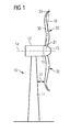
- a wind turbine 10 is shown.
- the wind turbine 10 comprises a nacelle 12 and a tower 11.
- the nacelle 12 is mounted at the top of the tower 11.
- the nacelle 12 is mounted rotatable with regard to the tower 11 by means of a yaw bearing.
- the axis of rotation of the nacelle 12 with regard to the tower 11 is referred to as the yaw axis.
- the wind turbine 10 also comprises a hub 13 with three rotor blades 20 (of which two rotor blades 20 are depicted in Figure 1 ).
- the hub 13 is mounted rotatable with regard to the nacelle 12 by means of a main bearing.
- the hub 13 is mounted rotatable about a rotor axis of rotation 14.
- the wind turbine 10 comprises furthermore a main shaft, which connects the hub 13 with a rotor of a generator 15.
- the hub 13 is connected directly to the rotor, thus the wind turbine 10 is referred to as a gearless, direct driven wind turbine.
- the hub 13 may also be connected to the rotor via a gearbox. This type of wind turbine is referred to as a geared wind turbine.
- the generator 15 is accommodated within the nacelle 12. It comprises the rotor and a stator. The generator 15 is arranged and prepared for converting the rotational energy from the rotor into electrical energy.
- the rotor blade 20 comprises a root portion 21 by which the rotor blade 20 is attached to the hub 13.
- the rotor blade 20 is mounted rotatable to the hub 13 and can be rotated about a pitch axis 16.
- the rotational movement about the pitch axis 16 is also referred to as a pitch movement.
- the rotor blade 20 furthermore comprises an aerodynamic portion 30 with a tip section 33.
- the aerodynamic portion 30 is strongly bent and curved in the example of Figure 1 .
- a minimum distance between the rotor blade 20 and the tower 11 is denoted as clearance 17.
- a meaningful value for the clearance 17 can only be determined with a rotating rotor blade 20. Otherwise, if the rotor blade 20 was non-rotating and at a position away from the tower 11, the distance between the rotor blade 20 and the tower 11 could be permanently very large and would not indicate the minimum distance between the rotor blade 20 and the tower 11.
- the value of the clearance 17 is important for assessing the risk of a collision between the rotor blade 20 and the tower 11. For instance, there may be a control mechanism which shuts down the wind turbine if a minimum value for the clearance 17 is undercut.
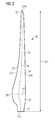
- Figure 2 shows a rotor blade 20 of a wind turbine.
- the rotor blade 20 comprises a root portion 21 with a root 211. Adjacent to the root portion 21 is the transition portion 22 which connects the root portion 21 and an aerodynamic portion 30 of the rotor blade 20.
- the transition portion 22 and the aerodynamic portion 30 are delineated by the shoulder 28.
- the shoulder is defined as the region where the chord line 27 comprises a maximum chord length.
- the aerodynamic portion 30 comprises a tip section 33 with a tip end 334.
- the root 211 and the tip end 334 are virtually connected by the span 26 which follows the shape of the rotor blade 20. If the rotor blade were a rectangular shaped object, the span 26 would be a straight line. However, as the rotor blade 20 features a varying thickness, the span 26 is slightly curved or bent as well. Note that if the rotor blade 20 was bent itself, then the span 26 would be bent, too.
- the rotor blade 20 furthermore comprises a leading edge section 24 with a leading edge 241 and a trailing edge section 23 with a trailing edge 231.
- the trailing edge section 23 surrounds the trailing edge 231.
- the leading edge section 24 surrounds the leading edge 241.
- chord line 27 which connects the leading edge 241 with the trailing edge 231 can be defined. Note that the chord line 27 is perpendicular to the span 26.
- the rotor blade 20 can be divided into an inboard section which comprises the half of the rotor blade 20 adjacent to the root portion 21 and an outboard section which comprises the half of the rotor blade 20 which is adjacent to the tip section 33.
- the length of the rotor blade 261 is determined by a straight line from the root 211 to the tip end 334.
- the tip section 33 is slightly bent out of the chordal plane of the connection section which connects the tip section 33 with the remaining aerodynamic portion 30. Due to the top view onto the pressure side of the rotor blade, the bending of the tip section 33 is not visible in Figure 2 .
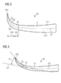
- Figure 3 shows a part of the aerodynamic portion 30 of a rotor blade in a view onto the trailing edge 231.
- the main pressure side 311 and the main suction side 312 can be well distinguished.
- the pressure side in particular the main pressure side 311, extends from the trailing edge 231 to the leading edge 241, which is not visible in Figure 3 .
- the aerodynamic device is relatively straight and plain until the tip section 33.
- the tip section 33 is strongly curved or bent.
- the tip section 33 comprises a tip pressure side 331 and a tip suction side 332.
- the tip section 33 and the main section 31 are connected by the connection section 32. Note that the main pressure side 311 and the tip pressure side 331 are on different sides of the rotor blade, in particular of the aerodynamic portion 30.
- connection section 32 The section of the aerodynamic portion 30 where the change of the sides occurs is the connection section 32. Likewise the main suction side 312 and the tip pressure side 331 are on different sides as well.
- the length of the connection section is referred to by the reference sign 321 and the length of the tip section is referred to the reference sign 333.
- Figure 4 shows the same aerodynamic portion 30 of a rotor blade as Figure 3 . This time, the angle 41 between the tip end 334 of the tip section 33 and the chordal plane 271 of the connection section 32 is illustrated. Note that as the connection section 32 extends over a certain curved section of the rotor blade, an average of the various spanwise chordal planes is taken and is used for determining the angle 41. In the example of Figure 4 the angle 41 amounts to approximately 40 degrees.
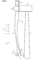
- Figure 5 shows another view of a wind turbine 10 with three rotor blades 20.
- One rotor blade 20 is shown in its full length. Additionally, the direction of the wind, generally speaking the airflow 42, is drawn. Regarding the clearance between the rotor blade 20 and the tower 11 of the wind turbine 10, two scenarios for the tip section of the rotor blade are shown and visualized in Figure 5 .
- a conventional rotor blade with a conventional tip section 337 is shown.
- the conventional tip section 337 comprises a bend out of the chordal plane of the connection section, wherein the tip section is bent away from the tower 11.
- the angle 41 is approximately 90 degrees.
- Such a tip section is also referred to as a winglet. In particular, it is referred to as a pressure side winglet.
- a conventional clearance 171 is identified.
- a tip section according to the invention 33 is shown in dashed lines. Due to the specific airfoil shape of the tip section 33 a bending moment induces the rotor blade to move away from the tower 11. As a consequence, the clearance 17 is changed by a clearance increase 172 compared to the conventional clearance 171. Thus, the risk of a collision between the rotor blade 20 and the tower 11 is mitigated.
- Figure 6 shows a first embodiment of a rotor blade. It comprises a main section 31 with an airfoil shape that is mainly characterized by the main pressure side 311 and the main suction side 312.
- the main section is bent out of its plane at the tip section 33 of the rotor blade.
- the airfoil profile looks at first similar to the airfoil from the main section 31.
- the connection section 32 the main suction side 312 changes into the tip pressure side 331 while the main pressure side 311 changes into the tip suction side 332.
- the tip section and the adjacent main section of the rotor blade looks like in a conventional rotor blade.
- a striking difference can be observed.
- Figure 8 shows a similar embodiment as Figure 6 , but this time the tip section is bent towards the main suction side 312. Again, the shapes of the airfoils in the main section 31 and in the tip section 33 are different. This again leads to lifting forces 43 that can be seen in Figure 9 . This time the tip section 33 is induced to a movement away from the main suction side 312. This will also decrease the clearance between the rotor blade and the tower of the wind turbine, which has to be imagined at the right of the Figure 9 if the rotor blade is once installed to the hub and the tower of a wind turbine.
- Figure 10 shows a double-sided tip section. This shape is known from double-sided winglets, for example. However, again, the shapes of the airfoils are different to existing winglets. Note that the side of the tip section 33 that is bent towards the main pressure side 311 is referred to as the first portion 335, while the section of the tip section 33 that is bent towards the main suction side 312 is referred to as the second portion 336.
- Figure 11 illustrates the lift forces of the tip section 33.
- the lift forces 43 that act on the tip suction side 332 of the first portion 335 and the lift forces 43 that act on the tip suction side 332 of the second portion 336 complement each other. They can be attributed to the same bending moment that is located somewhere in the center of the connection section 32. As a result, the first portion 335 is moved in clockwise direction, and the second portion 336 is moved in clockwise direction, too.
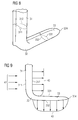
- Figure 12 shows a fourth embodiment of a rotor blade 20 with a bent tip section 33.
- the wind turbine 10 that is shown in Figure 12 also has pre-bent rotor blades 20.
- the tip sections 33 are only bent in a relatively small angle away from the chordal plane of the connection section.
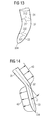
- Figure 13 shows a perspective view of the fourth embodiment of the rotor blade. Note that it is relatively similar to the rotor blade that is shown in Figure 6 with the only difference that the bending between the tip section 33 and the main section 31 is less pronounced. However, this has the advantage that forces that are generated at the tip section 33 are more easily and more efficiently transferred to the main section 31. Thus, the connection section 32 can be constructed less rigidly and stiffly.
- Figure 14 shows the same embodiment as in the two previous Figures but in a view onto the trailing edge of the rotor blade. Again, the angle 41 between the chordal plane of the connection section 32 and the tip end 334 can be seen and assessed.
- Figures 15 and 16 show a rotor blade that comprises a main section 31 and a tip section 33 with a connection section 32, the latter one being built as a separate extension part 44.
- the extension part 44 comprises the tip section 33, the connection section 32 and also an extension connection section 45. By means of the extension connection section 45, the extension part 44 is connected safely and reliably to the original tip section of the existing rotor blade.
Priority Applications (1)
| Application Number | Priority Date | Filing Date | Title |
|---|---|---|---|
| EP14182513.3A EP2990643B1 (fr) | 2014-08-27 | 2014-08-27 | Pale de rotor d'éolienne |
Applications Claiming Priority (1)
| Application Number | Priority Date | Filing Date | Title |
|---|---|---|---|
| EP14182513.3A EP2990643B1 (fr) | 2014-08-27 | 2014-08-27 | Pale de rotor d'éolienne |
Publications (2)
| Publication Number | Publication Date |
|---|---|
| EP2990643A1 true EP2990643A1 (fr) | 2016-03-02 |
| EP2990643B1 EP2990643B1 (fr) | 2018-02-21 |
Family
ID=51398578
Family Applications (1)
| Application Number | Title | Priority Date | Filing Date |
|---|---|---|---|
| EP14182513.3A Not-in-force EP2990643B1 (fr) | 2014-08-27 | 2014-08-27 | Pale de rotor d'éolienne |
Country Status (1)
| Country | Link |
|---|---|
| EP (1) | EP2990643B1 (fr) |
Cited By (8)
| Publication number | Priority date | Publication date | Assignee | Title |
|---|---|---|---|---|
| CN107061142A (zh) * | 2017-01-25 | 2017-08-18 | 北京博比风电科技有限公司 | 叶片和风力发电机组 |
| WO2018215037A1 (fr) * | 2017-05-22 | 2018-11-29 | Envision Energy (Denmark) Aps | Pale avec pré-déflexion pour éolienne du type à vent descendant |
| WO2019211304A1 (fr) * | 2018-05-02 | 2019-11-07 | Anakata Wind Power Resources Ltd | Structure d'extrémité de surface portante, en particulier pour une pale de rotor hawt |
| WO2019235344A1 (fr) * | 2018-06-08 | 2019-12-12 | 株式会社グローバルエナジー | Rotor à axe horizontal |
| CN110678646A (zh) * | 2018-04-17 | 2020-01-10 | 远景能源(江苏)有限公司 | 风力涡轮机的叶尖间隙、估算与控制 |
| EP3604796A1 (fr) * | 2018-07-30 | 2020-02-05 | SENVION GmbH | Pale de rotor pour une éolienne, éolienne, procédé d'extension d'une pale de rotor ainsi que procédé de fabrication d'une pale de rotor |
| CN114320732A (zh) * | 2020-09-30 | 2022-04-12 | 江苏金风科技有限公司 | 叶片、设计方法及风力发电机组 |
| WO2023213509A1 (fr) * | 2022-05-02 | 2023-11-09 | Lm Wind Power A/S | Pale d'éolienne pré-courbée optimisée pour une stabilité aéro-élastique |
Citations (9)
| Publication number | Priority date | Publication date | Assignee | Title |
|---|---|---|---|---|
| WO1999014490A1 (fr) | 1997-09-04 | 1999-03-25 | Lm Glasfiber A/S | Rotor d'eolienne et pales correspondantes |
| US20110142677A1 (en) * | 2010-11-16 | 2011-06-16 | General Electric Company | Winglet for wind turbine rotor blade |
| EP2339171A2 (fr) * | 2009-12-22 | 2011-06-29 | Siegfried Mickeler | Pale pour une éolienne |
| US20120027595A1 (en) * | 2011-08-09 | 2012-02-02 | General Electric Company | Pitchable winglet for a wind turbine rotor blade |
| DE102011056353A1 (de) | 2010-12-15 | 2012-06-21 | General Electric Company | Windturbinenrotorblatt |
| WO2013083130A1 (fr) * | 2011-12-09 | 2013-06-13 | Vestas Wind Systems A/S | Turbine éolienne comprenant des pales à ailette latérale d'aspiration |
| US20130251535A1 (en) | 2012-03-20 | 2013-09-26 | General Electric Company | Winglet for a wind turbine rotor blade |
| US20130259697A1 (en) * | 2012-03-30 | 2013-10-03 | General Electric Company | Enhanced wind turbine blade |
| EP2650535A1 (fr) * | 2012-04-10 | 2013-10-16 | Siemens Aktiengesellschaft | Ensemble formant pale de rotor pour éolienne |
-
2014
- 2014-08-27 EP EP14182513.3A patent/EP2990643B1/fr not_active Not-in-force
Patent Citations (9)
| Publication number | Priority date | Publication date | Assignee | Title |
|---|---|---|---|---|
| WO1999014490A1 (fr) | 1997-09-04 | 1999-03-25 | Lm Glasfiber A/S | Rotor d'eolienne et pales correspondantes |
| EP2339171A2 (fr) * | 2009-12-22 | 2011-06-29 | Siegfried Mickeler | Pale pour une éolienne |
| US20110142677A1 (en) * | 2010-11-16 | 2011-06-16 | General Electric Company | Winglet for wind turbine rotor blade |
| DE102011056353A1 (de) | 2010-12-15 | 2012-06-21 | General Electric Company | Windturbinenrotorblatt |
| US20120027595A1 (en) * | 2011-08-09 | 2012-02-02 | General Electric Company | Pitchable winglet for a wind turbine rotor blade |
| WO2013083130A1 (fr) * | 2011-12-09 | 2013-06-13 | Vestas Wind Systems A/S | Turbine éolienne comprenant des pales à ailette latérale d'aspiration |
| US20130251535A1 (en) | 2012-03-20 | 2013-09-26 | General Electric Company | Winglet for a wind turbine rotor blade |
| US20130259697A1 (en) * | 2012-03-30 | 2013-10-03 | General Electric Company | Enhanced wind turbine blade |
| EP2650535A1 (fr) * | 2012-04-10 | 2013-10-16 | Siemens Aktiengesellschaft | Ensemble formant pale de rotor pour éolienne |
Cited By (11)
| Publication number | Priority date | Publication date | Assignee | Title |
|---|---|---|---|---|
| CN107061142A (zh) * | 2017-01-25 | 2017-08-18 | 北京博比风电科技有限公司 | 叶片和风力发电机组 |
| WO2018215037A1 (fr) * | 2017-05-22 | 2018-11-29 | Envision Energy (Denmark) Aps | Pale avec pré-déflexion pour éolienne du type à vent descendant |
| CN110678646A (zh) * | 2018-04-17 | 2020-01-10 | 远景能源(江苏)有限公司 | 风力涡轮机的叶尖间隙、估算与控制 |
| CN110678646B (zh) * | 2018-04-17 | 2021-06-29 | 远景能源(江苏)有限公司 | 风力涡轮机的叶尖间隙、估算与控制 |
| WO2019211304A1 (fr) * | 2018-05-02 | 2019-11-07 | Anakata Wind Power Resources Ltd | Structure d'extrémité de surface portante, en particulier pour une pale de rotor hawt |
| US11428206B2 (en) | 2018-05-02 | 2022-08-30 | Anakata Wind Power Resources Ltd | Aerofoil tip structure, particularly for a HAWT rotor blade |
| WO2019235344A1 (fr) * | 2018-06-08 | 2019-12-12 | 株式会社グローバルエナジー | Rotor à axe horizontal |
| EP3604796A1 (fr) * | 2018-07-30 | 2020-02-05 | SENVION GmbH | Pale de rotor pour une éolienne, éolienne, procédé d'extension d'une pale de rotor ainsi que procédé de fabrication d'une pale de rotor |
| CN114320732A (zh) * | 2020-09-30 | 2022-04-12 | 江苏金风科技有限公司 | 叶片、设计方法及风力发电机组 |
| CN114320732B (zh) * | 2020-09-30 | 2023-12-15 | 江苏金风科技有限公司 | 叶片、设计方法及风力发电机组 |
| WO2023213509A1 (fr) * | 2022-05-02 | 2023-11-09 | Lm Wind Power A/S | Pale d'éolienne pré-courbée optimisée pour une stabilité aéro-élastique |
Also Published As
| Publication number | Publication date |
|---|---|
| EP2990643B1 (fr) | 2018-02-21 |
Similar Documents
| Publication | Publication Date | Title |
|---|---|---|
| EP2990643B1 (fr) | Pale de rotor d'éolienne | |
| EP2275672B1 (fr) | Ailettes de couche limite pour pale d'éolienne | |
| CN102046965B (zh) | 带有辅助翼面的风力涡轮机叶片 | |
| EP2341245B1 (fr) | Appareil pour augmenter la portance d'une pale d'éolienne | |
| EP2801720B1 (fr) | Ensemble de modification de flux d'air pour une pale de rotor d'une éolienne | |
| EP2194267B1 (fr) | Manche pour le pied d'une pale d'éolienne | |
| EP2589797B1 (fr) | Pale d'éolienne comprenant une surface portante secondaire montée sur une barrière anti décrochage de la pale | |
| AU2013213758B2 (en) | Wind turbine rotor blade | |
| EP2368035B1 (fr) | Pale d'éolienne dotée d'un déflecteur avec une séparation efficace de la circulation de l'air | |
| EP3037656B1 (fr) | Pale de rotor à générateurs de vortex | |
| DK178332B1 (en) | Wind turbine rotor wing with a winglet on the suction side and a wind turbine | |
| JP5479388B2 (ja) | 風車翼およびこれを備えた風力発電装置 | |
| US20120027588A1 (en) | Root flap for rotor blade in wind turbine | |
| EP2204578A2 (fr) | Plateau d'arc partiel pour pales d'éolienne | |
| US20150132141A1 (en) | Rotor blade of a wind turbine | |
| EP2784301B1 (fr) | Ensemble de pales de rotor pour éolienne possédant des caractéristiques de réduction de charge | |
| EP2937558B1 (fr) | Dispositif de déviation d'écoulement d'une éolienne et méthode | |
| EP3453872B1 (fr) | Procédés permettant d'atténuer le bruit pendant des conditions de vitesse du vent élevée d'éoliennes | |
| CN109690072B (zh) | 风能设备转子叶片 | |
| US20140169965A1 (en) | Wind turbine and the operation method of the same | |
| EP3098436B1 (fr) | Volet de réduction de bruit avec une ouverture | |
| JP2018119483A (ja) | 翼及びそれを用いた風車 | |
| CN102251931A (zh) | 一种垂直轴风力发电机 | |
| CN202140253U (zh) | 一种垂直轴风力发电机 | |
| WO2015145723A1 (fr) | Pale de turbine éolienne et générateur d'énergie éolienne la comportant |
Legal Events
| Date | Code | Title | Description |
|---|---|---|---|
| PUAI | Public reference made under article 153(3) epc to a published international application that has entered the european phase |
Free format text: ORIGINAL CODE: 0009012 |
|
| AK | Designated contracting states |
Kind code of ref document: A1 Designated state(s): AL AT BE BG CH CY CZ DE DK EE ES FI FR GB GR HR HU IE IS IT LI LT LU LV MC MK MT NL NO PL PT RO RS SE SI SK SM TR |
|
| AX | Request for extension of the european patent |
Extension state: BA ME |
|
| 17P | Request for examination filed |
Effective date: 20160720 |
|
| RBV | Designated contracting states (corrected) |
Designated state(s): AL AT BE BG CH CY CZ DE DK EE ES FI FR GB GR HR HU IE IS IT LI LT LU LV MC MK MT NL NO PL PT RO RS SE SI SK SM TR |
|
| RAP1 | Party data changed (applicant data changed or rights of an application transferred) |
Owner name: SIEMENS AKTIENGESELLSCHAFT |
|
| GRAP | Despatch of communication of intention to grant a patent |
Free format text: ORIGINAL CODE: EPIDOSNIGR1 |
|
| INTG | Intention to grant announced |
Effective date: 20170915 |
|
| GRAS | Grant fee paid |
Free format text: ORIGINAL CODE: EPIDOSNIGR3 |
|
| GRAA | (expected) grant |
Free format text: ORIGINAL CODE: 0009210 |
|
| AK | Designated contracting states |
Kind code of ref document: B1 Designated state(s): AL AT BE BG CH CY CZ DE DK EE ES FI FR GB GR HR HU IE IS IT LI LT LU LV MC MK MT NL NO PL PT RO RS SE SI SK SM TR |
|
| REG | Reference to a national code |
Ref country code: GB Ref legal event code: FG4D |
|
| REG | Reference to a national code |
Ref country code: CH Ref legal event code: EP |
|
| REG | Reference to a national code |
Ref country code: AT Ref legal event code: REF Ref document number: 972015 Country of ref document: AT Kind code of ref document: T Effective date: 20180315 |
|
| REG | Reference to a national code |
Ref country code: IE Ref legal event code: FG4D |
|
| REG | Reference to a national code |
Ref country code: DE Ref legal event code: R096 Ref document number: 602014021127 Country of ref document: DE |
|
| REG | Reference to a national code |
Ref country code: NL Ref legal event code: MP Effective date: 20180221 |
|
| REG | Reference to a national code |
Ref country code: LT Ref legal event code: MG4D |
|
| REG | Reference to a national code |
Ref country code: AT Ref legal event code: MK05 Ref document number: 972015 Country of ref document: AT Kind code of ref document: T Effective date: 20180221 |
|
| PG25 | Lapsed in a contracting state [announced via postgrant information from national office to epo] |
Ref country code: ES Free format text: LAPSE BECAUSE OF FAILURE TO SUBMIT A TRANSLATION OF THE DESCRIPTION OR TO PAY THE FEE WITHIN THE PRESCRIBED TIME-LIMIT Effective date: 20180221 Ref country code: NO Free format text: LAPSE BECAUSE OF FAILURE TO SUBMIT A TRANSLATION OF THE DESCRIPTION OR TO PAY THE FEE WITHIN THE PRESCRIBED TIME-LIMIT Effective date: 20180521 Ref country code: HR Free format text: LAPSE BECAUSE OF FAILURE TO SUBMIT A TRANSLATION OF THE DESCRIPTION OR TO PAY THE FEE WITHIN THE PRESCRIBED TIME-LIMIT Effective date: 20180221 Ref country code: CY Free format text: LAPSE BECAUSE OF FAILURE TO SUBMIT A TRANSLATION OF THE DESCRIPTION OR TO PAY THE FEE WITHIN THE PRESCRIBED TIME-LIMIT Effective date: 20180221 Ref country code: NL Free format text: LAPSE BECAUSE OF FAILURE TO SUBMIT A TRANSLATION OF THE DESCRIPTION OR TO PAY THE FEE WITHIN THE PRESCRIBED TIME-LIMIT Effective date: 20180221 Ref country code: FI Free format text: LAPSE BECAUSE OF FAILURE TO SUBMIT A TRANSLATION OF THE DESCRIPTION OR TO PAY THE FEE WITHIN THE PRESCRIBED TIME-LIMIT Effective date: 20180221 Ref country code: LT Free format text: LAPSE BECAUSE OF FAILURE TO SUBMIT A TRANSLATION OF THE DESCRIPTION OR TO PAY THE FEE WITHIN THE PRESCRIBED TIME-LIMIT Effective date: 20180221 |
|
| PG25 | Lapsed in a contracting state [announced via postgrant information from national office to epo] |
Ref country code: BG Free format text: LAPSE BECAUSE OF FAILURE TO SUBMIT A TRANSLATION OF THE DESCRIPTION OR TO PAY THE FEE WITHIN THE PRESCRIBED TIME-LIMIT Effective date: 20180521 Ref country code: GR Free format text: LAPSE BECAUSE OF FAILURE TO SUBMIT A TRANSLATION OF THE DESCRIPTION OR TO PAY THE FEE WITHIN THE PRESCRIBED TIME-LIMIT Effective date: 20180522 Ref country code: AT Free format text: LAPSE BECAUSE OF FAILURE TO SUBMIT A TRANSLATION OF THE DESCRIPTION OR TO PAY THE FEE WITHIN THE PRESCRIBED TIME-LIMIT Effective date: 20180221 Ref country code: SE Free format text: LAPSE BECAUSE OF FAILURE TO SUBMIT A TRANSLATION OF THE DESCRIPTION OR TO PAY THE FEE WITHIN THE PRESCRIBED TIME-LIMIT Effective date: 20180221 Ref country code: LV Free format text: LAPSE BECAUSE OF FAILURE TO SUBMIT A TRANSLATION OF THE DESCRIPTION OR TO PAY THE FEE WITHIN THE PRESCRIBED TIME-LIMIT Effective date: 20180221 Ref country code: RS Free format text: LAPSE BECAUSE OF FAILURE TO SUBMIT A TRANSLATION OF THE DESCRIPTION OR TO PAY THE FEE WITHIN THE PRESCRIBED TIME-LIMIT Effective date: 20180221 |
|
| PG25 | Lapsed in a contracting state [announced via postgrant information from national office to epo] |
Ref country code: EE Free format text: LAPSE BECAUSE OF FAILURE TO SUBMIT A TRANSLATION OF THE DESCRIPTION OR TO PAY THE FEE WITHIN THE PRESCRIBED TIME-LIMIT Effective date: 20180221 Ref country code: IT Free format text: LAPSE BECAUSE OF FAILURE TO SUBMIT A TRANSLATION OF THE DESCRIPTION OR TO PAY THE FEE WITHIN THE PRESCRIBED TIME-LIMIT Effective date: 20180221 Ref country code: AL Free format text: LAPSE BECAUSE OF FAILURE TO SUBMIT A TRANSLATION OF THE DESCRIPTION OR TO PAY THE FEE WITHIN THE PRESCRIBED TIME-LIMIT Effective date: 20180221 Ref country code: PL Free format text: LAPSE BECAUSE OF FAILURE TO SUBMIT A TRANSLATION OF THE DESCRIPTION OR TO PAY THE FEE WITHIN THE PRESCRIBED TIME-LIMIT Effective date: 20180221 Ref country code: RO Free format text: LAPSE BECAUSE OF FAILURE TO SUBMIT A TRANSLATION OF THE DESCRIPTION OR TO PAY THE FEE WITHIN THE PRESCRIBED TIME-LIMIT Effective date: 20180221 |
|
| REG | Reference to a national code |
Ref country code: DE Ref legal event code: R097 Ref document number: 602014021127 Country of ref document: DE |
|
| PG25 | Lapsed in a contracting state [announced via postgrant information from national office to epo] |
Ref country code: CZ Free format text: LAPSE BECAUSE OF FAILURE TO SUBMIT A TRANSLATION OF THE DESCRIPTION OR TO PAY THE FEE WITHIN THE PRESCRIBED TIME-LIMIT Effective date: 20180221 Ref country code: SK Free format text: LAPSE BECAUSE OF FAILURE TO SUBMIT A TRANSLATION OF THE DESCRIPTION OR TO PAY THE FEE WITHIN THE PRESCRIBED TIME-LIMIT Effective date: 20180221 Ref country code: SM Free format text: LAPSE BECAUSE OF FAILURE TO SUBMIT A TRANSLATION OF THE DESCRIPTION OR TO PAY THE FEE WITHIN THE PRESCRIBED TIME-LIMIT Effective date: 20180221 Ref country code: DK Free format text: LAPSE BECAUSE OF FAILURE TO SUBMIT A TRANSLATION OF THE DESCRIPTION OR TO PAY THE FEE WITHIN THE PRESCRIBED TIME-LIMIT Effective date: 20180221 |
|
| PGFP | Annual fee paid to national office [announced via postgrant information from national office to epo] |
Ref country code: GB Payment date: 20180809 Year of fee payment: 5 |
|
| PLBE | No opposition filed within time limit |
Free format text: ORIGINAL CODE: 0009261 |
|
| STAA | Information on the status of an ep patent application or granted ep patent |
Free format text: STATUS: NO OPPOSITION FILED WITHIN TIME LIMIT |
|
| 26N | No opposition filed |
Effective date: 20181122 |
|
| PGFP | Annual fee paid to national office [announced via postgrant information from national office to epo] |
Ref country code: DE Payment date: 20181019 Year of fee payment: 5 |
|
| PG25 | Lapsed in a contracting state [announced via postgrant information from national office to epo] |
Ref country code: SI Free format text: LAPSE BECAUSE OF FAILURE TO SUBMIT A TRANSLATION OF THE DESCRIPTION OR TO PAY THE FEE WITHIN THE PRESCRIBED TIME-LIMIT Effective date: 20180221 |
|
| PG25 | Lapsed in a contracting state [announced via postgrant information from national office to epo] |
Ref country code: MC Free format text: LAPSE BECAUSE OF FAILURE TO SUBMIT A TRANSLATION OF THE DESCRIPTION OR TO PAY THE FEE WITHIN THE PRESCRIBED TIME-LIMIT Effective date: 20180221 |
|
| REG | Reference to a national code |
Ref country code: CH Ref legal event code: PL |
|
| PG25 | Lapsed in a contracting state [announced via postgrant information from national office to epo] |
Ref country code: LU Free format text: LAPSE BECAUSE OF NON-PAYMENT OF DUE FEES Effective date: 20180827 Ref country code: LI Free format text: LAPSE BECAUSE OF NON-PAYMENT OF DUE FEES Effective date: 20180831 Ref country code: CH Free format text: LAPSE BECAUSE OF NON-PAYMENT OF DUE FEES Effective date: 20180831 |
|
| REG | Reference to a national code |
Ref country code: BE Ref legal event code: MM Effective date: 20180831 |
|
| REG | Reference to a national code |
Ref country code: DE Ref legal event code: R081 Ref document number: 602014021127 Country of ref document: DE Owner name: SIEMENS GAMESA RENEWABLE ENERGY A/S, DK Free format text: FORMER OWNER: SIEMENS AKTIENGESELLSCHAFT, 80333 MUENCHEN, DE |
|
| PG25 | Lapsed in a contracting state [announced via postgrant information from national office to epo] |
Ref country code: FR Free format text: LAPSE BECAUSE OF NON-PAYMENT OF DUE FEES Effective date: 20180831 Ref country code: BE Free format text: LAPSE BECAUSE OF NON-PAYMENT OF DUE FEES Effective date: 20180831 |
|
| REG | Reference to a national code |
Ref country code: GB Ref legal event code: 732E Free format text: REGISTERED BETWEEN 20191128 AND 20191204 |
|
| PG25 | Lapsed in a contracting state [announced via postgrant information from national office to epo] |
Ref country code: MT Free format text: LAPSE BECAUSE OF NON-PAYMENT OF DUE FEES Effective date: 20180827 |
|
| REG | Reference to a national code |
Ref country code: DE Ref legal event code: R119 Ref document number: 602014021127 Country of ref document: DE |
|
| PG25 | Lapsed in a contracting state [announced via postgrant information from national office to epo] |
Ref country code: TR Free format text: LAPSE BECAUSE OF FAILURE TO SUBMIT A TRANSLATION OF THE DESCRIPTION OR TO PAY THE FEE WITHIN THE PRESCRIBED TIME-LIMIT Effective date: 20180221 |
|
| GBPC | Gb: european patent ceased through non-payment of renewal fee |
Effective date: 20190827 |
|
| PG25 | Lapsed in a contracting state [announced via postgrant information from national office to epo] |
Ref country code: PT Free format text: LAPSE BECAUSE OF FAILURE TO SUBMIT A TRANSLATION OF THE DESCRIPTION OR TO PAY THE FEE WITHIN THE PRESCRIBED TIME-LIMIT Effective date: 20180221 |
|
| PG25 | Lapsed in a contracting state [announced via postgrant information from national office to epo] |
Ref country code: MK Free format text: LAPSE BECAUSE OF NON-PAYMENT OF DUE FEES Effective date: 20180221 Ref country code: HU Free format text: LAPSE BECAUSE OF FAILURE TO SUBMIT A TRANSLATION OF THE DESCRIPTION OR TO PAY THE FEE WITHIN THE PRESCRIBED TIME-LIMIT; INVALID AB INITIO Effective date: 20140827 Ref country code: IE Free format text: LAPSE BECAUSE OF NON-PAYMENT OF DUE FEES Effective date: 20180827 |
|
| PG25 | Lapsed in a contracting state [announced via postgrant information from national office to epo] |
Ref country code: DE Free format text: LAPSE BECAUSE OF NON-PAYMENT OF DUE FEES Effective date: 20200303 Ref country code: IS Free format text: LAPSE BECAUSE OF FAILURE TO SUBMIT A TRANSLATION OF THE DESCRIPTION OR TO PAY THE FEE WITHIN THE PRESCRIBED TIME-LIMIT Effective date: 20180621 |
|
| PG25 | Lapsed in a contracting state [announced via postgrant information from national office to epo] |
Ref country code: GB Free format text: LAPSE BECAUSE OF NON-PAYMENT OF DUE FEES Effective date: 20190827 |