EP2990622A1 - Muffler device and manufacturing method for muffler device - Google Patents
Muffler device and manufacturing method for muffler device Download PDFInfo
- Publication number
- EP2990622A1 EP2990622A1 EP15181633.7A EP15181633A EP2990622A1 EP 2990622 A1 EP2990622 A1 EP 2990622A1 EP 15181633 A EP15181633 A EP 15181633A EP 2990622 A1 EP2990622 A1 EP 2990622A1
- Authority
- EP
- European Patent Office
- Prior art keywords
- shell
- layer shell
- sheet
- inner layer
- muffler device
- Prior art date
- Legal status (The legal status is an assumption and is not a legal conclusion. Google has not performed a legal analysis and makes no representation as to the accuracy of the status listed.)
- Withdrawn
Links
Images




Classifications
-
- F—MECHANICAL ENGINEERING; LIGHTING; HEATING; WEAPONS; BLASTING
- F01—MACHINES OR ENGINES IN GENERAL; ENGINE PLANTS IN GENERAL; STEAM ENGINES
- F01N—GAS-FLOW SILENCERS OR EXHAUST APPARATUS FOR MACHINES OR ENGINES IN GENERAL; GAS-FLOW SILENCERS OR EXHAUST APPARATUS FOR INTERNAL-COMBUSTION ENGINES
- F01N1/00—Silencing apparatus characterised by method of silencing
- F01N1/08—Silencing apparatus characterised by method of silencing by reducing exhaust energy by throttling or whirling
- F01N1/10—Silencing apparatus characterised by method of silencing by reducing exhaust energy by throttling or whirling in combination with sound-absorbing materials
-
- F—MECHANICAL ENGINEERING; LIGHTING; HEATING; WEAPONS; BLASTING
- F01—MACHINES OR ENGINES IN GENERAL; ENGINE PLANTS IN GENERAL; STEAM ENGINES
- F01N—GAS-FLOW SILENCERS OR EXHAUST APPARATUS FOR MACHINES OR ENGINES IN GENERAL; GAS-FLOW SILENCERS OR EXHAUST APPARATUS FOR INTERNAL-COMBUSTION ENGINES
- F01N1/00—Silencing apparatus characterised by method of silencing
- F01N1/08—Silencing apparatus characterised by method of silencing by reducing exhaust energy by throttling or whirling
- F01N1/084—Silencing apparatus characterised by method of silencing by reducing exhaust energy by throttling or whirling the exhaust gases flowing through the silencer two or more times longitudinally in opposite directions, e.g. using parallel or concentric tubes
-
- F—MECHANICAL ENGINEERING; LIGHTING; HEATING; WEAPONS; BLASTING
- F01—MACHINES OR ENGINES IN GENERAL; ENGINE PLANTS IN GENERAL; STEAM ENGINES
- F01N—GAS-FLOW SILENCERS OR EXHAUST APPARATUS FOR MACHINES OR ENGINES IN GENERAL; GAS-FLOW SILENCERS OR EXHAUST APPARATUS FOR INTERNAL-COMBUSTION ENGINES
- F01N1/00—Silencing apparatus characterised by method of silencing
- F01N1/08—Silencing apparatus characterised by method of silencing by reducing exhaust energy by throttling or whirling
- F01N1/089—Silencing apparatus characterised by method of silencing by reducing exhaust energy by throttling or whirling using two or more expansion chambers in series
-
- F—MECHANICAL ENGINEERING; LIGHTING; HEATING; WEAPONS; BLASTING
- F01—MACHINES OR ENGINES IN GENERAL; ENGINE PLANTS IN GENERAL; STEAM ENGINES
- F01N—GAS-FLOW SILENCERS OR EXHAUST APPARATUS FOR MACHINES OR ENGINES IN GENERAL; GAS-FLOW SILENCERS OR EXHAUST APPARATUS FOR INTERNAL-COMBUSTION ENGINES
- F01N13/00—Exhaust or silencing apparatus characterised by constructional features
- F01N13/14—Exhaust or silencing apparatus characterised by constructional features having thermal insulation
-
- F—MECHANICAL ENGINEERING; LIGHTING; HEATING; WEAPONS; BLASTING
- F01—MACHINES OR ENGINES IN GENERAL; ENGINE PLANTS IN GENERAL; STEAM ENGINES
- F01N—GAS-FLOW SILENCERS OR EXHAUST APPARATUS FOR MACHINES OR ENGINES IN GENERAL; GAS-FLOW SILENCERS OR EXHAUST APPARATUS FOR INTERNAL-COMBUSTION ENGINES
- F01N13/00—Exhaust or silencing apparatus characterised by constructional features
- F01N13/18—Construction facilitating manufacture, assembly, or disassembly
- F01N13/1838—Construction facilitating manufacture, assembly, or disassembly characterised by the type of connection between parts of exhaust or silencing apparatus, e.g. between housing and tubes, between tubes and baffles
- F01N13/1844—Mechanical joints
- F01N13/185—Mechanical joints the connection being realised by deforming housing, tube, baffle, plate, or parts thereof
-
- F—MECHANICAL ENGINEERING; LIGHTING; HEATING; WEAPONS; BLASTING
- F01—MACHINES OR ENGINES IN GENERAL; ENGINE PLANTS IN GENERAL; STEAM ENGINES
- F01N—GAS-FLOW SILENCERS OR EXHAUST APPARATUS FOR MACHINES OR ENGINES IN GENERAL; GAS-FLOW SILENCERS OR EXHAUST APPARATUS FOR INTERNAL-COMBUSTION ENGINES
- F01N2260/00—Exhaust treating devices having provisions not otherwise provided for
- F01N2260/18—Exhaust treating devices having provisions not otherwise provided for for improving rigidity, e.g. by wings, ribs
-
- F—MECHANICAL ENGINEERING; LIGHTING; HEATING; WEAPONS; BLASTING
- F01—MACHINES OR ENGINES IN GENERAL; ENGINE PLANTS IN GENERAL; STEAM ENGINES
- F01N—GAS-FLOW SILENCERS OR EXHAUST APPARATUS FOR MACHINES OR ENGINES IN GENERAL; GAS-FLOW SILENCERS OR EXHAUST APPARATUS FOR INTERNAL-COMBUSTION ENGINES
- F01N2450/00—Methods or apparatus for fitting, inserting or repairing different elements
- F01N2450/22—Methods or apparatus for fitting, inserting or repairing different elements by welding or brazing
Definitions
- the invention relates to a muffler device in which an intermediate sheet serving as a damping material or a sound absorbing material is arranged between double-layered shells, and to a manufacturing method for the muffler device.
- JP 2010-190205 JP 2010-190205 A
- JP 2004-150310 JP 2004-150310 A
- a shell for a muffler device is structured by superimposing two metal plates on each other.
- JP 2004-150310 A a sound absorbing material is filled between the two metal plates.
- JP 2004-150310 A in order to exert a sound absorbing function of the sound absorbing material, it is necessary to provide the sound absorbing material at a given position. As described in JP 2004-150310 A , when the sound absorbing material is filled between the two metal plates, the position of the sound absorbing material could be shifted between the two metal plates due to vibration and so on of the shell while the muffler device is used. The position of the sound absorbing material could also be shifted when manufacturing the muffler device.
- the first aspect of the invention of this application is a muffler device, to which exhaust gas discharged from an internal combustion engine of a vehicle is introduced.
- the muffler device includes an outer layer shell, an inner layer shell, and an intermediate sheet.
- the outer layer shell is arranged on an outer surface of the muffler device, extends in a given direction, and is formed into a cylindrical shape.
- the inner layer shell is arranged on an inner side of the outer layer shell in the muffler device, extends in the given direction, and is formed into a cylindrical shape.
- the intermediate sheet is arranged between the outer layer shell and the inner layer shell and serves as a damping material or a sound absorbing material.
- One shell out of the outer layer shell and the inner layer shell includes a processed part that is processed into a shape projecting towards the other shell.
- the intermediate sheet includes a receiving part in a region that faces the processed part, and the receiving part is formed into a shape that allows the processed part to enter the receiving part.
- the receiving part is formed in the intermediate sheet in the region that faces the processed part, the receiving part is positioned around the processed part when the processed part enters the receiving part, thereby preventing the receiving part from shifting with respect to the processed part.
- By preventing the position of the intermediate sheet from shifting functions of the intermediate sheet as a damping material or a sound absorbing material are exerted easily.
- the one shell may include a plurality of the processed parts. Further, a plurality of the receiving parts, which correspond to the plurality of processed parts, respectively, may be formed in the intermediate sheet.
- the plurality of receiving parts may be formed at positions that are not aligned with each other in the given direction and a circumferential direction of the outer layer shell and the inner layer shell. Thus, it is possible to prevent the position of the intermediate sheet from shifting in the given direction and the circumferential direction.
- a bent part may be used, which is obtained by processing a part of the one shell.
- the processed part which projects towards the other shell, without changing the thickness of the shell.
- the muffler device of this invention is structured by using a shell having a uniform thickness like the related art.
- the muffler device may include a separator.
- the separator has a flange that is formed along an inner peripheral surface of the inner layer shell, and divides a space formed on an inner side of the inner layer shell into a plurality of spaces that are lined up in the given direction.
- the receiving part may have a hole that allows the processed part to go through the hole and allows the processed part to come into contact with the other shell.
- the flange, the processed part, and the other shell can be superimposed on each other and welded to each other. Since the receiving part having the hole allows the processed part to come into contact with the other shell, it is possible to weld the flange, the processed part, and the other shell to each other easily, thereby ensuring strength of the welded part easily.
- the receiving part may have a recessed part other than the hole.
- the second aspect of the invention of this application is a manufacturing method for the muffler device according to the first aspect of the invention.
- a processed part is formed in a shell sheet that structures an outer layer shell and an inner layer shell, and an intermediate sheet is superimposed on the shell sheet by allowing the processed part to enter a receiving part. Then, by forming the shell sheet, on which the intermediate sheet is superimposed, into a cylindrical shape, the outer layer shell and the inner layer shell that sandwich the intermediate sheet are formed.
- the intermediate sheet it is possible to position the intermediate sheet with respect to the shell sheet by allowing the processed part to enter the receiving part.
- the muffler device it is possible to position the intermediate sheet at a given position. Therefore, functions of the intermediate sheet as a damping material or a sound absorbing material are exerted easily.
- the shell sheet When the outer layer shell and the inner layer shell are formed, the shell sheet may be formed into a cylindrical shape by winding the shell sheet around the separator while giving a tension to the shell sheet. By giving a tension to the shell sheet, it is possible to bring the intermediate sheet into close contact with the outer layer shell and the inner layer shell when the outer layer shell and the inner layer shell are formed. Thus, the functions of the intermediate sheet as a damping material or a sound absorbing material are exerted easily.
- the third aspect of the invention of this application is a manufacturing method for the muffler device according to the first aspect of the invention of this application.
- a processed part is formed in a first shell sheet that structures one of shells, the processed part is allowed to enter a receiving part, and an intermediate sheet is sandwiched between a second shell sheet that structures the other shell, and the first shell sheet. Then, the first shell sheet and the second shell sheet, which sandwich the intermediate sheet, is formed into a cylindrical shape, thereby forming an outer layer shell and an inner layer shell, respectively.
- the intermediate sheet it is possible to position the intermediate sheet with respect to the first shell sheet by allowing the processed part to enter the receiving part. It is thus possible to form the outer layer shell and the inner layer shell while positioning the intermediate sheet, thereby preventing the position of the intermediate sheet from shifting when the muffler device is manufactured.
- the muffler device it is possible to position the intermediate sheet at a given position, thereby exerting functions of the intermediate sheet as a damping material or a sound absorbing material.
- the first shell sheet and the second shell sheet are wound around the separator while giving a tension to the shell sheets.
- the functions of the intermediate sheet as a damping material or a sound absorbing material are exerted easily.
- the intermediate sheet may include a plurality of receiving parts formed at positions that are not aligned with each other in a given direction and a circumferential direction of the outer layer shell and the inner layer shell.
- the one shell may include a plurality of the processed parts that correspond to the plurality of receiving parts, respectively.
- the receiving part may have a hole that allows the processed part to go through the hole so that the processed part comes into contact with the other shell.
- the receiving part having the hole allows the processed part to come into contact with the other shell, it is possible to weld the processed part and the other shell to each other easily, thereby ensuring strength of the welded part easily.
- FIG. 1 is an exterior view of a muffler device 1.
- FIG. 2 is a sectional view taken along the line A1 - A1 in FIG. 1
- FIG. 3 is a sectional view taken along the line A2 - A2 in FIG. 1.
- FIG. 1 is an exterior view of the muffler device 1 seen from an arrow B1 shown in FIG. 2 and an arrow B2 shown in FIG. 3 .
- a pair of end covers 11, 12 and a shell 20 structure an outer surface of the muffler device 1.
- the shell 20 is formed into a cylindrical shape, and extends in a longitudinal direction of the muffler device 1 (the horizontal direction in FIG. 1 , corresponding to a given direction of the invention). Opening parts are formed on both ends of the shell 20 in the longitudinal direction of the muffler device 1, and the opening parts are closed by the metallic end covers 11, 12, respectively.
- Each of the end covers 11, 12 is fixed to the shell 20 by welding.
- the shell 20 has a double-layer structure, and includes an outer layer shell 21 and an inner layer shell 22.
- the outer layer shell 21 and the inner layer shell 22 are both formed into a cylindrical shape, and extend in the longitudinal direction of the muffler device 1.
- the outer layer shell 21 is arranged on an outer surface of the muffler device 1
- the inner layer shell 22 is arranged on an inner side of the outer layer shell 21 in muffler device 1.
- the outer layer shell 21 and the inner layer shell 22 are formed from one metallic shell sheet.
- the inner layer shell 22 is arranged along outer edges of the separators 31 to 34, and a flange is provided in the outer edge of each of the separators 31 to 34, and is in contact with an inner peripheral surface of the inner layer shell 22.
- Each of the separators 31 to 34 divides a space formed inside the inner layer shell 22 into five spaces S1 to S5. Each of the spaces S1 to S5 is used as an expansion chamber for exhaust gas.
- the spaces S1 is a space surrounded by the end cover 11, the separator 31, and a part of the inner layer shell 22, and the space S2 is a space surrounded by the separators 31, 32 and a part of the inner layer shell 22.
- the space S3 is a space surrounded by the separators 32, 33 and a part of the inner layer shell 22, and the space S4 is a space surrounded by the separators 33, 34 and a part of the inner layer shell 22.
- the space S5 is a space surrounded by the separator 34, the end cover 12, and a part of the inner layer shell 22.
- the four separators 31 to 34 are provided. However, the number of the separators may be set as appropriate.
- a metallic first exhaust pipe 41 goes through the end cover 11 and each of the separators 31 to 34.
- One end part 41 a of the first exhaust pipe 41 is located outside the muffler device 1, and is connected with one end part of an introduction pipe (not shown).
- the other end part of the introduction pipe is connected with an exhaust port of an internal combustion engine of a vehicle.
- gas discharged from the exhaust port exhaust gas
- exhaust gas gas
- each of the separators 31 to 34 opening parts are formed for allowing exhaust gas to pass through.
- the separator 32 has an opening part 32a for allowing exhaust gas to go through.
- a metallic second exhaust pipe 42 passes through the end cover 12 and each of the separators 31 to 34.
- One end part 42a of the second exhaust pipe 42 is located outside the muffler device 1, and the other end part 42b of the second exhaust pipe 42 is located inside the spaces S1.
- exhaust gas that has moved to the spaces S1 is lead from the other end part 42b into the second exhaust pipe 42, and discharged from one end part 42a.
- a plurality of bent parts (corresponding to processed parts of the invention) 21a are provided in the outer layer shell 21, and the bent parts 21a are formed by bending parts of the outer layer shell 21 so as to project towards the inner side of the shell 20.
- a thickness of the bent part 21 a is equal to a thickness of the outer layer shell 21 excluding the bent parts 21a.
- the plurality of bent parts 21a are arranged along the outer edge of each of the separators 31 to 34, and a part where the bent part 21 a, the inner layer shell 22, and each of the separators 31 to 34 are superimposed each other is welded.
- two intermediate sheets 50 are arranged between the outer layer shell 21 and the inner layer shell 22.
- the intermediate sheets 50 are sandwiched between the outer layer shell 21 and the inner layer shell 22.
- the intermediate sheets 50 are formed from a material having heat resistance because temperature of the muffler device 1 becomes high due to heat from exhaust gas.
- the intermediate sheet 50 may have a function of damping vibration (damping function).
- a sheet formed from carbon expansion graphite and so on
- the intermediate sheets 50 are able to damp vibration of the outer layer shell 21 and the inner layer shell 22. As vibration of the outer layer shell 21 and the inner layer shell 22 are damped, it is possible to reduce sound generated with the vibration.
- the intermediate sheets 50 may also have a function of absorbing sound (sound absorbing function).
- a sheet made from, for example, glass wool may be used as the intermediate sheets 50 absorb sound generated due to vibration of the outer layer shell 21 and the inner layer shell 22, it is possible to reduce sound transmitted outside the muffler device 1.
- the intermediate sheets 50 are arranged at positions in the muffler device 1, where vibration and sound are prone to be generated.
- a length of the muffler device 1 in the horizontal direction is smaller than a length of the muffler device 1 in the vertical direction in FIG. 2 . Therefore, vibration and sound are prone to be generated on both side surfaces of the shell 20 in the horizontal direction in FIG. 2 .
- the intermediate sheets 50 are arranged between the outer layer shell 21 and the inner layer shell 22 on both side surfaces of the shell 20 in the horizontal direction in FIG. 2 .
- the positions where the intermediate sheet 50 are arranged are not limited to the positions shown in FIG. 2 .
- Positions for arranging the intermediate sheets 50 may be set in advance in consideration of a vibrational state of the shell 20, as well as a sound generation state from the shell 20. In order to exert the damping function and the sound absorbing function, it is necessary to arrange the intermediate sheets 50 without allowing the intermediate sheets 50 from shifting from the previously-set given positions. Meanwhile, in this example, the two intermediate sheets 50 are provided. However, the number of the intermediate sheets 50 may be one, three or more.
- FIG. 4 is a view showing the muffler device 1 shown in FIG. 1 in which the outer layer shell 21 is omitted.
- FIG. 4 shows an exterior view of one of the intermediate sheets 50 out of the two intermediate sheets 50.
- the two intermediate sheets 50 have the same structure.
- the intermediate sheet 50 has a plurality of (specifically, 16) holes (corresponding to receiving parts of the invention) 51, and each of the holes 51 passes through the intermediate sheet 50.
- Each of the bent parts 21a formed in the outer layer shell 21 enters an inner side of each of the holes 51.
- the bent part 21a of the outer layer shell 21 projects towards the inner layer shell 22 and enters the inner side of the hole 51.
- FIG. 5 shows a structure of a part of the muffler device 1 that is cut in the longitudinal direction of the muffler device 1.
- the hole 51 is formed in a region that faces the bent part 21 a, and is also formed along an outline of the bent part 21 a.
- the bent part 21 a that enters the inner side of the hole 51 is in contact with the outer peripheral surface of the inner layer shell 22.
- the bent part 21a projects towards the inner layer shell 22 by the thickness of the intermediate sheet 50.
- a flange 32b is provided in an outer edge of the separator 32.
- the flange 32b is formed along an inner peripheral surface of the inner layer shell 22, and is also in contact with the inner peripheral surface of the inner layer shell 22.
- a flange similar to the flange 32b is also provided in each of the separators 31, 33,34.
- FIG. 5 a part where the bent part 21 a, the inner layer shell 22, and the flange 32b are superimposed on each other is welded.
- the outer layer shell 21 and the inner layer shell 22 are fixed to the separator 32.
- the flange of each of the separators 31, 33, 34 is superimposed on the inner layer shell 22 and the bent part 21a, and the superimposed part is welded.
- the outer layer shell 21 and the inner layer shell 22 are fixed to the separators 31, 33, 34.
- FIG. 6 shows a state before a shell sheet 23 is wound around the end covers 11, 12 and the separators 31 to 34.
- the first exhaust pipe 41 and the second exhaust pipe 42 are connected with the end covers 11, 12 and the separators 31 to 34.
- FIG. 7 is a view of the shell sheet 23 and the intermediate sheets 50 seen from a direction of an arrow C shown in FIG. 6 . In FIG. 7 , the end covers 11, 12 and the separators 31 to 34 are omitted.
- the shell sheet 23 is welded to the end covers 11, 12 at a position P11. Then, by rotating the end covers 11, 12 and the separators 31 to 34 in a direction of arrows R1 shown in FIG. 6 , the shell sheet 23 is wound around the end covers 11, 12 and the separators 31 to 34. As the shell sheet 23 is wound around the end covers 11, 12 and the separators 31 to 34 from the position P11 up to a position P12 of the shell sheet 23, the end covers 11, 12 and the separators 31 to 34 are surrounded by the shell sheet 23, thereby forming the cylindrical-shaped inner layer shell 22.
- the cylindrical-shaped outer layer shell 21 is formed.
- the shell sheet 23 is welded to the end covers 11, 12 at the position P13. As stated so far, by doubly winding the shell sheet 23 with respect to the end covers 11, 12 and the separators 31 to 34, the shell 20 is formed.
- Each of the two intermediate sheets 50 is superimposed in a region between the position P12 and the position P13 in the shell sheet 23.
- the plurality of bent parts 21a are formed in advance, and each of the bent parts 21a enters the inner side of each of the holes 51 of the intermediate sheets 50.
- the intermediate sheets 50 are sandwiched between the inner layer shell 22 and the outer layer shell 21.
- the shell sheet 23 is wound around the end covers 11, 12 and the separators 31 to 34 while giving a tension to the shell sheet 23. In this way, the intermediate sheets 50 are easily brought into close contact with the outer layer shell 21 and the inner layer shell 22.
- the shell 20 is formed by winding the shell sheet 23 around the end covers 11, 12 and the separators 31 to 34, laser welding, for example, is performed on the bent parts 21a from an outer side of the shell 20.
- laser welding for example, is performed on the bent parts 21a from an outer side of the shell 20.
- the part where the bent part 21a, the inner layer shell 22, and the flange of each of the respective separators 31 to 34 are superimposed on each other is welded.
- the muffler device 1 is completed. Since the bent parts 21a are formed in the outer layer shell 21, the bent parts 21a may be used as marks when laser welding is performed.
- the manufacturing method for the muffler device 1 is not limited to the method stated above. Another manufacturing method for the muffler device 1 is explained below.
- the cylindrical-shaped shell 20 is formed by winding only the shell sheet 23, on which the intermediate sheets 50 are superimposed. At this time, the end covers 11, 12 and the separators 31 to 34 are not assembled to the shell 20. When the cylindrical-shaped shell 20 is formed, the intermediate sheets 50 are sandwiched between the outer layer shell 21 and the inner layer shell 22.
- each of the separators 31 to 34 is inserted into an inner side of the cylindrical-shaped shell 20. At this time, each of the separators 31 to 34 is inserted so that the flange of each of the separators 31 to 34 is superimposed on the bent part 21a through the inner layer shell 22.
- a pair of jigs are arranged at positions that sandwich the flange of each of the separators 31 to 34, the inner layer shell 22, and the bent part 21a, and electric current is flown between the pair of jigs, thereby welding the flange of each of the separators 31 to 34, the inner layer shell 22, and the bent part 21a to one another.
- the separators 31 to 34 are inserted to the inner side of the shell 20 and welded in order.
- the end covers 11, 12 are welded to the cylindrical-shaped shell 20.
- the first exhaust pipe 41 may be assembled to the end cover 11 and the separators 31 to 34
- the second exhaust pipe 42 may be assembled to the end cover 12 and the separators 31 to 34.
- the bent part 21a of the outer layer shell 21 enters the inner side of the hole 51 of the intermediate sheet 50, and is welded to the inner layer shell 22 and each of the separators 31 to 34.
- the hole 51 is formed in the region that faces the bent part 21a. Therefore, when the bent part 21a enters the inner side of the hole 51, the hole 51 is positioned around the bent part 21 a.
- the bent part 21 a is provided in the outer layer shell 21 in advance, it is possible to weld the bent part 21a, the inner layer shell 22, and the flange of each of the separators 31 to 34 to each other easily, and it is thus possible to ensure strength of the welded part easily. Also, it is possible to prevent deformation of the outer layer shell 21 when welding the outer layer shell 21 and the inner layer shell 22 to each other.
- the bent part 21a since the bent part 21a is used, it is not necessary to deform the outer layer shell 21. Thus, it is possible to prevent the intermediate sheet 50 from being crushed by the outer layer shell 21, and a crack is prevented from happening from the hole 51. Further, since a part of the outer layer shell 21 is not stretched when welded, it is possible to ensure strength of the outer layer shell 21.
- the bent part 21a it is possible to project a part of the outer layer shell 21 towards the inner layer shell 22 without changing the thickness of the outer layer shell 21.
- Providing at least two holes 51 makes it possible to prevent the intermediate sheet 50 from shifting in the longitudinal direction of the muffler device 1
- FIG. 8 is a view corresponding to FIG. 4 .
- the holes 51A are the same as the hole 51 explained in this example.
- the two holes 51A are formed at positions that are not aligned with each other in the longitudinal direction of the muffler device 1 (the horizontal direction in FIG. 8 ), and the circumferential direction of the shell 20 (the vertical direction in FIG. 8 ). Therefore, by using the two holes 51A, it is possible to position the intermediate sheet 50 in the longitudinal direction of the muffler device 1 and the circumferential direction of the shell 20.
- the positions where the holes 51A are provided are not limited to the positions shown in FIG. 8 .
- the two holes 51A only need to be formed at positions that are not aligned with each other in the longitudinal direction of the muffler device 1 and the circumferential direction of the shell 20.
- the holes 51B are formed in a region larger than the region that faces the bent part 21a, and do not have the function of positioning the intermediate sheet 50.
- the holes 51B are formed so as to allow the bent parts 21a to come into contact with the inner layer shell 22 and allow the bent parts 21a, the inner layer shell 22, and the flange of each of the separators 31 to 34 to be welded to each other.
- the muffler device 1 when the muffler device 1 is manufactured, it is possible to position the intermediate sheets 50 with respect to the shell sheet 23 by allowing the bent parts 21a to enter the holes 51. Then, in a state where the intermediate sheets 50 are positioned on the shell sheet 23, the shell sheet 23 and the intermediate sheets 50 are wound around the end covers 11, 12 and the separators 31 to 34.
- a muffler device according to the second example of the invention is explained.
- the same reference numerals are used for members having the same functions as the members explained in the first example, and detailed explanation is omitted. Differences from the first example are mainly explained below.
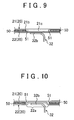
- FIG. 9 is a view corresponding to FIG. 5 .
- an outer layer shell 21 includes a body part 21b and a projecting part (corresponding to the processed part according to the invention) 21c.
- the outer layer shell 21 includes a part having a thickness of the body part 21b only, and a part having a thickness of the body part 21b and the projecting part 21c.
- the projecting part 21c is formed into a shape that protrudes from the body part 21b towards an inner layer shell 22.
- the projecting part 21c enters an inner side of a hole 51 of an intermediate sheet 50, and is in contact with the inner layer shell 22.
- the thickness of the projecting part 21c is equal to the thickness of the intermediate sheet 50.
- the hole 51 is formed in the intermediate sheet 50 in a region that faces the projecting part 21c.
- the body part 21b and the projecting part 21c may be formed integrally with each other, or the body part 21b and the projecting part 21c may be structured separately, and the projecting part 21c may be fixed to the body part 21b.
- the muffler device 1 It is possible to manufacture the muffler device 1 according to this example in a method similar to that of the first example. It is sufficient that the projecting part 21c is formed, instead of the bent part 21 a, in advance in the shell sheet 23 shown in FIG. 6 and FIG. 7 .
- the hole 51 by using the hole 51, it is possible to prevent the intermediate sheet 50 from shifting when the muffler device 1 is used or manufactured.
- the projecting part 21c by allowing the projecting part 21c to enter the inner side of the hole 51 and come into contact with the inner layer shell 22, it is possible to weld the outer layer shell 21, the inner layer shell 22, and a flange of each of the separators 31 to 34 to each other easily. Therefore, it is possible to ensure strength of the welded part easily.
- a muffler device according to the third example of the invention is explained.
- the same reference numerals are used for members having the same functions as the members explained in the first example, and detailed explanation is omitted. Differences from the first example are mainly explained below.
- the bent part 21a is formed in the outer layer shell 21.
- a bent part 21 a of an outer layer shell 21 is omitted, and a bent part 22a is formed in an inner layer shell 22 as shown in FIG. 10.
- FIG. 10 is a view corresponding to FIG. 5 .
- the bent part 22a is formed by bending a part of the inner layer shell 22.
- the thickness of the bent part 22a is equal to the thickness of the inner layer shell 22 excluding the bent part 22a.
- the bent part 22a is formed in a shape that protrudes towards the outer layer shell 21, enters a hole 51 in an intermediate sheet 50, and is in contact with the outer layer shell 21.
- FIG. 11 is a view of the separator 32 seen from the longitudinal direction of the muffler device 1.
- FIG. 11 shows not only the separator 32 but also a first exhaust pipe 41 and a second exhaust pipe 42.
- the separator 32 has a projecting part 32c at a position corresponding to the bent part 22a. Since the bent part 22a projects towards the outer layer shell 21, the projecting part 32c is formed in the separator 32 as well. Thus, the flange 32b, which is formed in an outer edge of the separator 32, is arranged along the inner layer shell 22 including the bent part 22a.
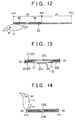
- FIG. 12 is a view corresponding to FIG. 6 .
- the shell sheet 23 is welded to end covers 11, 12 at a position P21. Then, by rotating the end covers 11, 12 and the separators 31 to 34 in a direction of arrows R2 in FIG. 12 , the shell sheet 23 is wound around the end covers 11, 12 and the separators 31 to 34.
- the first exhaust pipe 41 and the second exhaust pipe 42 are connected with the end covers 11, 12 and the separators 31 to 34.
- the cylindrical-shaped inner layer shell 22 is formed.
- the two intermediate sheets 50 are superimposed respectively in a region between the position P21 and the position P22 in the shell sheet 23.
- the plurality of bent parts 22a are formed in advance. Each of the bent parts 22a enters the inner side of the hole 51 of the intermediate sheet 50. Thus, the intermediate sheet 50 is positioned with respect to the shell sheet 23.
- the projecting part 32c of the separator 32 shown in FIG. 11 enters an inner side of the bent part 22a (in short, a recessed part). Further, when the inner layer shell 22 is formed, the intermediate sheets 50 are arranged on an outer peripheral surface of the inner layer shell 22.
- the cylindrical-shaped outer layer shell 21 is formed.
- the shell sheet 23 is welded to the end covers 11, 12 at the position P23.
- the intermediate sheets 50 are sandwiched between the inner layer shell 22 and the outer layer shell 21.
- the shell 20 is formed by winding the shell sheet 23 around the end covers 11, 12 and the separators 31 to 34, laser welding, for example, is performed from an outer side of the shell 20.
- laser welding for example, is performed from an outer side of the shell 20.
- a part where the outer layer shell 21, the bent part 22a, and the flange of each of the separators 31 to 34 are superimposed on each other is welded.
- the muffler device 1 is completed.
- the hole 51 is formed in the intermediate sheet 50 in a region that faces the bent part 22a, when the bent part 22a enters the inner side of the hole 51, the hole 51 is positioned around the bent part 22a. Therefore, it is unlikely that the hole 51 is shifted with respect to the welded bent part 22a.
- the intermediate sheet 50 similarly to the first example, it is possible to prevent the intermediate sheet 50 from shifting when the muffler device 1 is used or manufactured.
- the bent part 22a By allowing the bent part 22a to enter the inner side of the hole 51 and come into contact with the outer layer shell 21, the outer layer shell 21, the inner layer shell 22, and the flange of each of the separators 31 to 34 are welded to each other easily, thereby ensuring strength of the welded part easily. Moreover, by using the bent part 22a, it is possible to allow a part of the inner layer shell 22 to project towards the outer layer shell 21 without changing the thickness of the inner layer shell 22. In other words, similarly to the related art, it is possible to structure the muffler device 1 by using the inner layer shell 22 having a uniform thickness.
- FIG. 13 is a view corresponding to FIG. 9 .
- an inner layer shell 22 has a body part 22b and a projecting part 22c.
- the inner layer shell 22 includes a part having a thickness of the body part 22b only, and a part having a thickness of the body part 22b and the projecting part 22c.
- the projecting part 22c is formed in a shape that protrudes towards an outer layer shell 21 from the body part 22b.
- the projecting part 22c enters an inner side of a hole 51 of an intermediate sheet 50 and comes into contact with the outer layer shell 21.
- the thickness of the projecting part 22c is equal to the thickness of the intermediate sheet 50.
- the body part 22b and the projecting part 22c may be formed integrally with each other, or the body part 22b and the projecting part 22c may be structured separately and then the projecting part 22c may be fixed to the body part 22b.
- a muffler device 1 according to this modified example is manufactured in a method similar to that of the first example.
- the muffler device 1 may be manufactured by winding a shell sheet 23 around end covers 11, 12 and separators 31 to 34, or the muffler device 1 may be manufactured by assembling the separators 31 to 34 and the end covers 11, 12 to a shell 20 formed into a cylindrical shape. It is only necessary to form the projecting part 22c, instead of the bent part 22a, in advance in the shell sheet 23 shown in FIG. 12 .
- the projecting part 22c and the hole 51 it is possible to prevent the intermediate sheet 50 from shifting when the muffler device 1 is used or manufactured. Further, by allowing the projecting part 22c to enter an inner side of the hole 51 and come into contact with the outer layer shell 21, the outer layer shell 21, the inner layer shell 22, and a flange of each of the separators 31 to 34 are welded to each other easily, thereby ensuring strength of the welded part easily.
- a muffler device according to the fourth example of the invention is explained.
- the same reference numerals are used for members having the same functions as the members explained in the first to third examples, and detailed explanation is omitted. Differences from the first to third examples are mainly explained below.
- the outer layer shell 21 and the inner layer shell 22 are formed by winding one shell sheet 23 around the end covers 11, 12 and the separators 31 to 34. Meanwhile, in this example, an outer layer shell 21 and an inner layer shell 22 are formed from separate shell sheets.
- an intermediate sheet 50 is arranged between a shell sheet 23A that structures the outer layer shell 21, and a shell sheet 23B that structures the inner layer shell 22, and the shell sheets 23A, 23B and the intermediate sheet 50 are superimposed on each other.
- the bent part 21a explained in the first example, or the projecting part 21c explained in the second example may be formed in the shell sheet 23A.
- the bent part 22a or the projecting part 22c explained in the third example may be formed in the shell sheet 23B.
- FIG. 15 is a sectional view showing a structure of a shell 20 and the intermediate sheet 50, and corresponds to FIG. 2 .
- the separators 31 to 34 arranged on an inner side of the shell 20 are omitted.
- the intermediate sheet 50 is easily brought into close contact with the outer layer shell 21 and the inner layer shell 22, thereby easily exerting the given functions (the foregoing damping function and sound absorbing function) using the intermediate sheet 50.
- Both ends of the shell sheet 23A at the positions P31, P32 may abut against each other and be welded, and both ends of the shell sheet 23B at the positions P31, P32 may abut against each other and be welded.
- both ends of a layered body of the shell sheets 23A, 23B at the positions P31, P32 may be superimposed on and welded to each other, when the layered body is wound.
- the manufacturing method for the muffler device 1 is not limited to the methods described above.
- the cylindrical-shaped shell 20 can be formed in advance by winding the layered body in which the shell sheets 23A, 23B and the intermediate sheet 50 are layered. Then, each of the separators 31 to 34 may be inserted in the inner side of the cylindrical-shaped shell 20, and each of the separators 31 to 34 may be welded to the shell 20.
- the outer layer shell 21 and the inner layer shell 22 are structured separately, it is also possible to position the intermediate sheet 50 similarly to each of the first to third examples. Therefore, the intermediate sheet 50 is prevented from shifting when the muffler device 1 is used or manufactured. Further, similarly to the first to third examples, the outer layer shell 21, the inner layer shell 22, and the flange of each of the separators 31 to 34 is welded to each other easily, thereby ensuring strength of the welded part easily.
- the hole 51 is formed in the intermediate sheet 50.
- the invention is not limited to this.
- a recessed part (the receiving part according to the invention) 52 may be formed in the intermediate sheet 50.
- FIG. 16 is a sectional view in a thickness direction of the intermediate sheet 50, and corresponds to FIG. 5 , FIG. 9 , FIG. 10 , and FIG. 13 .
- the recessed part 52 opens upwardly in FIG. 16 .
- the recessed part 52 may be formed at the same position as the hole 51 shown in FIG. 5 and FIG. 9 . In this case, the recessed part 52 is open towards the outer layer shell 21.
- the bent part 21a shown in FIG. 5 , or the projecting part 21c shown in FIG. 9 may enter an inner side of the recessed part 52.
- the recessed part 52 may also be formed at the same position as the hole 51 shown in FIG. 10 or FIG. 13 . At this time, the recessed part 52 opens towards the inner layer shell 22.
- the bent part 22a shown in FIG. 10 or the projecting part 22c shown in FIG. 13 may enter the inner side of the recessed part 52.
- the recessed part 52 when the recessed part 52 is formed in the intermediate sheet 50, it is not possible to weld the outer layer shell 21, the inner layer shell 22, and the flange of each of the separators 31 to 34 to each other at the position where the recessed part 52 is formed. In this case, it is possible to weld the outer layer shell 21, the inner layer shell 22, and the flange of each of the separators 31 to 34 to each other at a location where the intermediate sheet 50 is not arranged.
- the location where the intermediate sheet 50 is arranged is, for example, an upper part or a lower part of the muffler device 1 in FIG. 2 .
- the recessed parts 52 may be formed at the same positions as those of the holes 51A.
- the recessed parts 52 may be used as substitution for all of the holes 51A, or may be used as substation for a part of the holes 51 A.
Landscapes
- Engineering & Computer Science (AREA)
- Chemical & Material Sciences (AREA)
- Combustion & Propulsion (AREA)
- Mechanical Engineering (AREA)
- General Engineering & Computer Science (AREA)
- Exhaust Silencers (AREA)
Abstract
One shell out of an outer layer shell (21) and an inner layer shell (22) has a processed part (21a) that is processed into a shape protruding towards the other shell. An intermediate sheet (50) includes a receiving part (51) in a region that faces the processed part, and the receiving part (51) is formed into a shape that allows the processed part to enter the receiving part. Since the receiving part is formed in the intermediate sheet in a region that faces the processed part, the receiving part is positioned around the processed part when the processed part enters the receiving part, thereby preventing the receiving part from shifting with respect to the processed part.
Description
- The invention relates to a muffler device in which an intermediate sheet serving as a damping material or a sound absorbing material is arranged between double-layered shells, and to a manufacturing method for the muffler device.
- In Japanese Patent Application Publication No.
2010-190205 JP 2010-190205 A 2004-150310 JP 2004-150310 A JP 2004-150310 A - In
JP 2004-150310 A JP 2004-150310 A - The first aspect of the invention of this application is a muffler device, to which exhaust gas discharged from an internal combustion engine of a vehicle is introduced. The muffler device includes an outer layer shell, an inner layer shell, and an intermediate sheet. The outer layer shell is arranged on an outer surface of the muffler device, extends in a given direction, and is formed into a cylindrical shape. The inner layer shell is arranged on an inner side of the outer layer shell in the muffler device, extends in the given direction, and is formed into a cylindrical shape. The intermediate sheet is arranged between the outer layer shell and the inner layer shell and serves as a damping material or a sound absorbing material.
- One shell out of the outer layer shell and the inner layer shell includes a processed part that is processed into a shape projecting towards the other shell. The intermediate sheet includes a receiving part in a region that faces the processed part, and the receiving part is formed into a shape that allows the processed part to enter the receiving part.
- According to the first aspect of the invention of this application, since the receiving part is formed in the intermediate sheet in the region that faces the processed part, the receiving part is positioned around the processed part when the processed part enters the receiving part, thereby preventing the receiving part from shifting with respect to the processed part. In short, it is possible to position the intermediate sheet by using the processed part and the receiving part, and it is thus possible to prevent the position of the intermediate sheet from shifting with respect to the inner layer shell and the outer layer shell when the muffler device is used. By preventing the position of the intermediate sheet from shifting, functions of the intermediate sheet as a damping material or a sound absorbing material are exerted easily.
- The one shell may include a plurality of the processed parts. Further, a plurality of the receiving parts, which correspond to the plurality of processed parts, respectively, may be formed in the intermediate sheet. The plurality of receiving parts may be formed at positions that are not aligned with each other in the given direction and a circumferential direction of the outer layer shell and the inner layer shell. Thus, it is possible to prevent the position of the intermediate sheet from shifting in the given direction and the circumferential direction.
- As the processed part, a bent part may be used, which is obtained by processing a part of the one shell. Thus, it is possible to structure the processed part, which projects towards the other shell, without changing the thickness of the shell. In other words, the muffler device of this invention is structured by using a shell having a uniform thickness like the related art.
- The muffler device may include a separator. The separator has a flange that is formed along an inner peripheral surface of the inner layer shell, and divides a space formed on an inner side of the inner layer shell into a plurality of spaces that are lined up in the given direction. The receiving part may have a hole that allows the processed part to go through the hole and allows the processed part to come into contact with the other shell. Thus, the flange, the processed part, and the other shell can be superimposed on each other and welded to each other. Since the receiving part having the hole allows the processed part to come into contact with the other shell, it is possible to weld the flange, the processed part, and the other shell to each other easily, thereby ensuring strength of the welded part easily. The receiving part may have a recessed part other than the hole.
- The second aspect of the invention of this application is a manufacturing method for the muffler device according to the first aspect of the invention. In this manufacturing method, a processed part is formed in a shell sheet that structures an outer layer shell and an inner layer shell, and an intermediate sheet is superimposed on the shell sheet by allowing the processed part to enter a receiving part. Then, by forming the shell sheet, on which the intermediate sheet is superimposed, into a cylindrical shape, the outer layer shell and the inner layer shell that sandwich the intermediate sheet are formed.
- According to the second aspect of the invention of this application, it is possible to position the intermediate sheet with respect to the shell sheet by allowing the processed part to enter the receiving part. Thus, it is possible to form the outer layer shell and the inner layer shell while positioning the intermediate sheet, thereby preventing the position of the intermediate sheet from shifting when the muffler device is manufactured. When the muffler device is manufactured, it is possible to position the intermediate sheet at a given position. Therefore, functions of the intermediate sheet as a damping material or a sound absorbing material are exerted easily.
- When the outer layer shell and the inner layer shell are formed, the shell sheet may be formed into a cylindrical shape by winding the shell sheet around the separator while giving a tension to the shell sheet. By giving a tension to the shell sheet, it is possible to bring the intermediate sheet into close contact with the outer layer shell and the inner layer shell when the outer layer shell and the inner layer shell are formed. Thus, the functions of the intermediate sheet as a damping material or a sound absorbing material are exerted easily.
- The third aspect of the invention of this application is a manufacturing method for the muffler device according to the first aspect of the invention of this application. In this manufacturing method, a processed part is formed in a first shell sheet that structures one of shells, the processed part is allowed to enter a receiving part, and an intermediate sheet is sandwiched between a second shell sheet that structures the other shell, and the first shell sheet. Then, the first shell sheet and the second shell sheet, which sandwich the intermediate sheet, is formed into a cylindrical shape, thereby forming an outer layer shell and an inner layer shell, respectively.
- According to the third aspect of the invention of this application, it is possible to position the intermediate sheet with respect to the first shell sheet by allowing the processed part to enter the receiving part. It is thus possible to form the outer layer shell and the inner layer shell while positioning the intermediate sheet, thereby preventing the position of the intermediate sheet from shifting when the muffler device is manufactured. When the muffler device is manufactured, it is possible to position the intermediate sheet at a given position, thereby exerting functions of the intermediate sheet as a damping material or a sound absorbing material.
- When the outer layer shell and the inner layer shell are formed, the first shell sheet and the second shell sheet are wound around the separator while giving a tension to the shell sheets. This makes it possible to bring the intermediate sheet into close contact with the outer layer shell and the inner layer shell. Thus, the functions of the intermediate sheet as a damping material or a sound absorbing material are exerted easily.
- In the second and third aspects of the invention of this application, the intermediate sheet may include a plurality of receiving parts formed at positions that are not aligned with each other in a given direction and a circumferential direction of the outer layer shell and the inner layer shell. Further, the one shell may include a plurality of the processed parts that correspond to the plurality of receiving parts, respectively. When the muffler device is manufactured, it is possible to position the intermediate sheet in the given direction and the circumferential direction by allowing each of the processed parts to enter each of the receiving parts.
- In the second and third aspects of the invention of this application, the receiving part may have a hole that allows the processed part to go through the hole so that the processed part comes into contact with the other shell. Thus, it is possible to superimpose and weld the flange, the processed part, and the other shell to each other. Since the receiving part having the hole allows the processed part to come into contact with the other shell, it is possible to weld the processed part and the other shell to each other easily, thereby ensuring strength of the welded part easily.
- Features, advantages, and technical and industrial significance of exemplary embodiments of the invention will be described below with reference to the accompanying drawings, in which like numerals denote like elements, and wherein:
-
FIG. 1 is an exterior view of a muffler device according to the first example; -
FIG. 2 is a sectional view of the muffler device according to the first example; -
FIG. 3 is a sectional view of the muffler device according to the first example; -
FIG. 4 is an exterior view of the muffler device according to the first example, in which an outer layer shell is omitted; -
FIG. 5 is a sectional view showing a part of a structure of the muffler device according to the first example; -
FIG. 6 is a view explaining a manufacturing method for the muffler device according to the first example; -
FIG. 7 is a top view of a shell sheet on which intermediate sheets are superimposed according to the first example; -
FIG. 8 is an exterior view of the muffler device according to a modified example of the first example, in which the outer layer shell is omitted; -
FIG. 9 is a sectional view showing a part of a structure of a muffler device according to the second example; -
FIG. 10 is a sectional view showing a part of a structure of a muffler device according to the third example; -
FIG. 11 is a view showing an outline of a separator according to the third example; -
FIG. 12 is a view explaining a manufacturing method for the muffler device according to the third example; -
FIG. 13 is a sectional view showing a part of a structure of a muffler device according to a modified example of the third example; -
FIG. 14 is a view explaining a manufacturing method for a muffler device according to the fourth example; -
FIG. 15 is a sectional view showing a structure of a shell according to the fourth example; and -
FIG. 16 is a sectional view of an intermediate sheet according to a modified example of the first to fourth examples. - Examples of the invention is explained below.
- A muffler device according to this example is explained.
FIG. 1 is an exterior view of a muffler device 1.FIG. 2 is a sectional view taken along the line A1 - A1 inFIG. 1 , andFIG. 3 is a sectional view taken along the line A2 - A2 inFIG. 1. FIG. 1 is an exterior view of the muffler device 1 seen from an arrow B1 shown inFIG. 2 and an arrow B2 shown inFIG. 3 . - A pair of end covers 11, 12 and a
shell 20 structure an outer surface of the muffler device 1. Theshell 20 is formed into a cylindrical shape, and extends in a longitudinal direction of the muffler device 1 (the horizontal direction inFIG. 1 , corresponding to a given direction of the invention). Opening parts are formed on both ends of theshell 20 in the longitudinal direction of the muffler device 1, and the opening parts are closed by the metallic end covers 11, 12, respectively. Each of the end covers 11, 12 is fixed to theshell 20 by welding. - As shown in
FIG. 2 andFIG. 3 , theshell 20 has a double-layer structure, and includes anouter layer shell 21 and aninner layer shell 22. Theouter layer shell 21 and theinner layer shell 22 are both formed into a cylindrical shape, and extend in the longitudinal direction of the muffler device 1. Theouter layer shell 21 is arranged on an outer surface of the muffler device 1, and theinner layer shell 22 is arranged on an inner side of theouter layer shell 21 in muffler device 1. As stated later, theouter layer shell 21 and theinner layer shell 22 are formed from one metallic shell sheet. - Inside the
inner layer shell 22, fourmetallic separators 31 to 34 are arranged. Theinner layer shell 22 is arranged along outer edges of theseparators 31 to 34, and a flange is provided in the outer edge of each of theseparators 31 to 34, and is in contact with an inner peripheral surface of theinner layer shell 22. Each of theseparators 31 to 34 divides a space formed inside theinner layer shell 22 into five spaces S1 to S5. Each of the spaces S1 to S5 is used as an expansion chamber for exhaust gas. - The spaces S1 is a space surrounded by the
end cover 11, theseparator 31, and a part of theinner layer shell 22, and the space S2 is a space surrounded by theseparators inner layer shell 22. The space S3 is a space surrounded by theseparators 32, 33 and a part of theinner layer shell 22, and the space S4 is a space surrounded by theseparators 33, 34 and a part of theinner layer shell 22. The space S5 is a space surrounded by theseparator 34, theend cover 12, and a part of theinner layer shell 22. In this example, the fourseparators 31 to 34 are provided. However, the number of the separators may be set as appropriate. - A metallic
first exhaust pipe 41 goes through theend cover 11 and each of theseparators 31 to 34. Oneend part 41 a of thefirst exhaust pipe 41 is located outside the muffler device 1, and is connected with one end part of an introduction pipe (not shown). The other end part of the introduction pipe is connected with an exhaust port of an internal combustion engine of a vehicle. Thus, gas discharged from the exhaust port (exhaust gas) is introduced to the muffler device 1. - Since the
other end part 41b of thefirst exhaust pipe 41 is located inside the space S5, exhaust gas from the exhaust port moves inside thefirst exhaust pipe 41 and is discharged from theother end part 41b to the space S5. Exhaust gas discharged into the space S5 moves through the space S4, the space S3, the space S2, and the spaces S1 in this order. In each of theseparators 31 to 34, opening parts are formed for allowing exhaust gas to pass through. For example, as shown inFIG. 2 andFIG. 3 , theseparator 32 has anopening part 32a for allowing exhaust gas to go through. - A metallic
second exhaust pipe 42 passes through theend cover 12 and each of theseparators 31 to 34. Oneend part 42a of thesecond exhaust pipe 42 is located outside the muffler device 1, and theother end part 42b of thesecond exhaust pipe 42 is located inside the spaces S1. As stated above, exhaust gas that has moved to the spaces S1 is lead from theother end part 42b into thesecond exhaust pipe 42, and discharged from oneend part 42a. - As shown in
FIG. 1 andFIG. 3 , a plurality of bent parts (corresponding to processed parts of the invention) 21a are provided in theouter layer shell 21, and thebent parts 21a are formed by bending parts of theouter layer shell 21 so as to project towards the inner side of theshell 20. A thickness of thebent part 21 a is equal to a thickness of theouter layer shell 21 excluding thebent parts 21a. As shown inFIG. 1 , the plurality ofbent parts 21a are arranged along the outer edge of each of theseparators 31 to 34, and a part where thebent part 21 a, theinner layer shell 22, and each of theseparators 31 to 34 are superimposed each other is welded. - As shown in
FIG. 2 , twointermediate sheets 50 are arranged between theouter layer shell 21 and theinner layer shell 22. In short, theintermediate sheets 50 are sandwiched between theouter layer shell 21 and theinner layer shell 22. Theintermediate sheets 50 are formed from a material having heat resistance because temperature of the muffler device 1 becomes high due to heat from exhaust gas. - The
intermediate sheet 50 may have a function of damping vibration (damping function). As theintermediate sheet 50 having the damping function, a sheet formed from carbon (expansion graphite and so on) may be used. When exhaust gas is lead into the muffler device 1, theouter layer shell 21 and theinner layer shell 22 vibrate. By arranging theintermediate sheets 50 having the damping function between theouter layer shell 21 and theinner layer shell 22, theintermediate sheets 50 are able to damp vibration of theouter layer shell 21 and theinner layer shell 22. As vibration of theouter layer shell 21 and theinner layer shell 22 are damped, it is possible to reduce sound generated with the vibration. - Meanwhile, the
intermediate sheets 50 may also have a function of absorbing sound (sound absorbing function). As theintermediate sheet 50 having the sound absorbing function, a sheet made from, for example, glass wool, may be used. As theintermediate sheets 50 absorb sound generated due to vibration of theouter layer shell 21 and theinner layer shell 22, it is possible to reduce sound transmitted outside the muffler device 1. - The
intermediate sheets 50 are arranged at positions in the muffler device 1, where vibration and sound are prone to be generated. In the sectional view of the muffler device 1 shown inFIG. 2 , a length of the muffler device 1 in the horizontal direction is smaller than a length of the muffler device 1 in the vertical direction inFIG. 2 . Therefore, vibration and sound are prone to be generated on both side surfaces of theshell 20 in the horizontal direction inFIG. 2 . Thus, in this example, as shown inFIG. 2 , theintermediate sheets 50 are arranged between theouter layer shell 21 and theinner layer shell 22 on both side surfaces of theshell 20 in the horizontal direction inFIG. 2 . - The positions where the
intermediate sheet 50 are arranged are not limited to the positions shown inFIG. 2 . Positions for arranging theintermediate sheets 50 may be set in advance in consideration of a vibrational state of theshell 20, as well as a sound generation state from theshell 20. In order to exert the damping function and the sound absorbing function, it is necessary to arrange theintermediate sheets 50 without allowing theintermediate sheets 50 from shifting from the previously-set given positions. Meanwhile, in this example, the twointermediate sheets 50 are provided. However, the number of theintermediate sheets 50 may be one, three or more. -
FIG. 4 is a view showing the muffler device 1 shown inFIG. 1 in which theouter layer shell 21 is omitted.FIG. 4 shows an exterior view of one of theintermediate sheets 50 out of the twointermediate sheets 50. The twointermediate sheets 50 have the same structure. - As shown in
FIG. 4 , theintermediate sheet 50 has a plurality of (specifically, 16) holes (corresponding to receiving parts of the invention) 51, and each of theholes 51 passes through theintermediate sheet 50. Each of thebent parts 21a formed in theouter layer shell 21 enters an inner side of each of theholes 51. To be specific, as shown inFIG. 5 , thebent part 21a of theouter layer shell 21 projects towards theinner layer shell 22 and enters the inner side of thehole 51.FIG. 5 shows a structure of a part of the muffler device 1 that is cut in the longitudinal direction of the muffler device 1. - In the
intermediate sheet 50, thehole 51 is formed in a region that faces thebent part 21 a, and is also formed along an outline of thebent part 21 a. Thebent part 21 a that enters the inner side of thehole 51 is in contact with the outer peripheral surface of theinner layer shell 22. Thebent part 21a projects towards theinner layer shell 22 by the thickness of theintermediate sheet 50. - As shown in
FIG. 5 , aflange 32b is provided in an outer edge of theseparator 32. Theflange 32b is formed along an inner peripheral surface of theinner layer shell 22, and is also in contact with the inner peripheral surface of theinner layer shell 22. A flange similar to theflange 32b is also provided in each of theseparators - In
FIG. 5 , a part where thebent part 21 a, theinner layer shell 22, and theflange 32b are superimposed on each other is welded. Thus, theouter layer shell 21 and theinner layer shell 22 are fixed to theseparator 32. Similarly, the flange of each of theseparators inner layer shell 22 and thebent part 21a, and the superimposed part is welded. Thus, theouter layer shell 21 and theinner layer shell 22 are fixed to theseparators - Next, a manufacturing method for the muffler device 1 is explained with reference to
FIG. 6 andFIG. 7 . -
FIG. 6 shows a state before ashell sheet 23 is wound around the end covers 11, 12 and theseparators 31 to 34. Thefirst exhaust pipe 41 and thesecond exhaust pipe 42 are connected with the end covers 11, 12 and theseparators 31 to 34.FIG. 7 is a view of theshell sheet 23 and theintermediate sheets 50 seen from a direction of an arrow C shown inFIG. 6 . InFIG. 7 , the end covers 11, 12 and theseparators 31 to 34 are omitted. - First of all, the
shell sheet 23 is welded to the end covers 11, 12 at a position P11. Then, by rotating the end covers 11, 12 and theseparators 31 to 34 in a direction of arrows R1 shown inFIG. 6 , theshell sheet 23 is wound around the end covers 11, 12 and theseparators 31 to 34. As theshell sheet 23 is wound around the end covers 11, 12 and theseparators 31 to 34 from the position P11 up to a position P12 of theshell sheet 23, the end covers 11, 12 and theseparators 31 to 34 are surrounded by theshell sheet 23, thereby forming the cylindrical-shapedinner layer shell 22. - Next, as the
shell sheet 23 is wound around the end covers 11, 12 and theseparators 31 to 34 from the position P12 up to a position P13 of theshell sheet 23, the cylindrical-shapedouter layer shell 21 is formed. Theshell sheet 23 is welded to the end covers 11, 12 at the position P13. As stated so far, by doubly winding theshell sheet 23 with respect to the end covers 11, 12 and theseparators 31 to 34, theshell 20 is formed. - Each of the two
intermediate sheets 50 is superimposed in a region between the position P12 and the position P13 in theshell sheet 23. In the region between the position P12 and the position P13 in theshell sheet 23, the plurality ofbent parts 21a are formed in advance, and each of thebent parts 21a enters the inner side of each of theholes 51 of theintermediate sheets 50. Thus, it is possible to position theintermediate sheets 50 with respect to theshell sheet 23. - When the
outer layer shell 21 is formed by winding theshell sheet 23, theintermediate sheets 50 are sandwiched between theinner layer shell 22 and theouter layer shell 21. At this time, theshell sheet 23 is wound around the end covers 11, 12 and theseparators 31 to 34 while giving a tension to theshell sheet 23. In this way, theintermediate sheets 50 are easily brought into close contact with theouter layer shell 21 and theinner layer shell 22. - After the
shell 20 is formed by winding theshell sheet 23 around the end covers 11, 12 and theseparators 31 to 34, laser welding, for example, is performed on thebent parts 21a from an outer side of theshell 20. Thus, the part where thebent part 21a, theinner layer shell 22, and the flange of each of therespective separators 31 to 34 are superimposed on each other is welded. Thus, the muffler device 1 is completed. Since thebent parts 21a are formed in theouter layer shell 21, thebent parts 21a may be used as marks when laser welding is performed. - The manufacturing method for the muffler device 1 is not limited to the method stated above. Another manufacturing method for the muffler device 1 is explained below.
- First of all, the cylindrical-shaped
shell 20 is formed by winding only theshell sheet 23, on which theintermediate sheets 50 are superimposed. At this time, the end covers 11, 12 and theseparators 31 to 34 are not assembled to theshell 20. When the cylindrical-shapedshell 20 is formed, theintermediate sheets 50 are sandwiched between theouter layer shell 21 and theinner layer shell 22. - Next, each of the
separators 31 to 34 is inserted into an inner side of the cylindrical-shapedshell 20. At this time, each of theseparators 31 to 34 is inserted so that the flange of each of theseparators 31 to 34 is superimposed on thebent part 21a through theinner layer shell 22. Next, a pair of jigs are arranged at positions that sandwich the flange of each of theseparators 31 to 34, theinner layer shell 22, and thebent part 21a, and electric current is flown between the pair of jigs, thereby welding the flange of each of theseparators 31 to 34, theinner layer shell 22, and thebent part 21a to one another. - After a separator out of the
separators 31 to 34 is inserted to the inner side of theshell 20 and welded, the next separator is inserted to the inner side of theshell 20 and welded. In this way, theseparators 31 to 34 are inserted to the inner side of theshell 20 and welded in order. After welding of theseparators 31 to 34 is finished, the end covers 11, 12 are welded to the cylindrical-shapedshell 20. Thereafter, thefirst exhaust pipe 41 may be assembled to theend cover 11 and theseparators 31 to 34, and thesecond exhaust pipe 42 may be assembled to theend cover 12 and theseparators 31 to 34. Thus, the muffler device 1 is completed. - Operations and effects of this example are explained.
- In the muffler device 1, the
bent part 21a of theouter layer shell 21 enters the inner side of thehole 51 of theintermediate sheet 50, and is welded to theinner layer shell 22 and each of theseparators 31 to 34. In theintermediate sheet 50, thehole 51 is formed in the region that faces thebent part 21a. Therefore, when thebent part 21a enters the inner side of thehole 51, thehole 51 is positioned around thebent part 21 a. - Therefore, it is unlikely that the
hole 51 is shifted with respect to the weldedbent part 21a. Accordingly, it is possible to prevent theintermediate sheets 50 from shifting between theouter layer shell 21 and theinner layer shell 22. By preventing theintermediate sheets 50 from shifting, it is possible to make theintermediate sheets 50 remain arranged at given positions, and it is thus possible to exert the given functions (the aforementioned damping function and sound absorbing function) using theintermediate sheet 50. - In this example, since the
bent part 21 a is provided in theouter layer shell 21 in advance, it is possible to weld thebent part 21a, theinner layer shell 22, and the flange of each of theseparators 31 to 34 to each other easily, and it is thus possible to ensure strength of the welded part easily. Also, it is possible to prevent deformation of theouter layer shell 21 when welding theouter layer shell 21 and theinner layer shell 22 to each other. - When the
outer layer shell 21 and theinner layer shell 22 are welded to each other without forming thebent part 21a in theouter layer shell 21, it can be considered that a part of theouter layer shell 21 is deformed and inserted to the inner side of thehole 51. In this case, when theouter layer shell 21 is deformed, andintermediate sheet 50 could be crushed and a crack could occur from thehole 51. When a part of theouter layer shell 21 is deformed and welded, since the part of theouter layer shell 21 is welded in a stretched state, the welded part of theouter layer shell 21 becomes thinner, and it is likely that strength of theouter layer shell 21 is reduced. - In this example, as stated above, since the
bent part 21a is used, it is not necessary to deform theouter layer shell 21. Thus, it is possible to prevent theintermediate sheet 50 from being crushed by theouter layer shell 21, and a crack is prevented from happening from thehole 51. Further, since a part of theouter layer shell 21 is not stretched when welded, it is possible to ensure strength of theouter layer shell 21. - Meanwhile, by using the
bent part 21a, it is possible to project a part of theouter layer shell 21 towards theinner layer shell 22 without changing the thickness of theouter layer shell 21. In other words, similarly to the related art, it is possible to structure the muffler device 1 by using theouter layer shell 21 having a uniform thickness. - Providing at least two
holes 51 makes it possible to prevent theintermediate sheet 50 from shifting in the longitudinal direction of the muffler device 1 - (the horizontal direction in
FIG. 4 ) and a circumferential direction of theshell 20. The twoholes 51 only need to be formed at positions that are not aligned with one another in the longitudinal direction of the muffler device 1 and the circumferential direction of theshell 20. For example, as shown inFIG. 8 , in theintermediate sheet 50, it is possible to form twoholes 51A used for positioning theintermediate sheet 50, and a plurality ofholes 51B that are not used for positioning of theintermediate sheet 50.FIG. 8 is a view corresponding toFIG. 4 . - The
holes 51A are the same as thehole 51 explained in this example. The twoholes 51A are formed at positions that are not aligned with each other in the longitudinal direction of the muffler device 1 (the horizontal direction inFIG. 8 ), and the circumferential direction of the shell 20 (the vertical direction inFIG. 8 ). Therefore, by using the twoholes 51A, it is possible to position theintermediate sheet 50 in the longitudinal direction of the muffler device 1 and the circumferential direction of theshell 20. - The positions where the
holes 51A are provided are not limited to the positions shown inFIG. 8 . As stated above, when at least twoholes 51A are provided, the twoholes 51A only need to be formed at positions that are not aligned with each other in the longitudinal direction of the muffler device 1 and the circumferential direction of theshell 20. Also, there may be only onehole 51A that is used for positioning of theintermediate sheet 50. In this case, it is also possible to prevent theintermediate sheet 50 from shifting because thehole 51A is fixed. - In the
intermediate sheet 50, theholes 51B are formed in a region larger than the region that faces thebent part 21a, and do not have the function of positioning theintermediate sheet 50. Theholes 51B are formed so as to allow thebent parts 21a to come into contact with theinner layer shell 22 and allow thebent parts 21a, theinner layer shell 22, and the flange of each of theseparators 31 to 34 to be welded to each other. - Next, when the muffler device 1 is manufactured, it is possible to position the
intermediate sheets 50 with respect to theshell sheet 23 by allowing thebent parts 21a to enter theholes 51. Then, in a state where theintermediate sheets 50 are positioned on theshell sheet 23, theshell sheet 23 and theintermediate sheets 50 are wound around the end covers 11, 12 and theseparators 31 to 34. - This makes it possible to prevent the
intermediate sheet 50 from shifting with respect to theshell sheet 23 when winding theshell sheet 23. It is thus possible to arrange theintermediate sheets 50 at the given positions between theouter layer shell 21 and theinner layer shell 22, and the given functions (the foregoing damping function and sound absorbing function) using theintermediate sheets 50 are exerted easily. As stated earlier, by providing at least twoholes 51, it is possible to prevent theintermediate sheet 50 from shifting with respect to theshell sheet 23 in the longitudinal direction of the muffler device 1 and the circumferential direction of theshell 20. - Further, by winding the
shell sheet 23 around the end covers 11, 12 and theseparators 31 to 34 while giving a tension to theshell sheet 23, it is possible to allow theintermediate sheet 50 to come into close contact with theouter layer shell 21 and theinner layer shell 22. Thus, it is possible to exert the given functions (the foregoing damping function and sound absorbing function) using theintermediate sheet 50 easily. - A muffler device according to the second example of the invention is explained. In this example, the same reference numerals are used for members having the same functions as the members explained in the first example, and detailed explanation is omitted. Differences from the first example are mainly explained below.
- A muffler device 1 according to this example is explained with reference to
FIG. 9. FIG. 9 is a view corresponding toFIG. 5 . As shown inFIG. 9 , anouter layer shell 21 includes abody part 21b and a projecting part (corresponding to the processed part according to the invention) 21c. Theouter layer shell 21 includes a part having a thickness of thebody part 21b only, and a part having a thickness of thebody part 21b and the projectingpart 21c. - The projecting
part 21c is formed into a shape that protrudes from thebody part 21b towards aninner layer shell 22. The projectingpart 21c enters an inner side of ahole 51 of anintermediate sheet 50, and is in contact with theinner layer shell 22. The thickness of the projectingpart 21c is equal to the thickness of theintermediate sheet 50. Thehole 51 is formed in theintermediate sheet 50 in a region that faces the projectingpart 21c. Thebody part 21b and the projectingpart 21c may be formed integrally with each other, or thebody part 21b and the projectingpart 21c may be structured separately, and the projectingpart 21c may be fixed to thebody part 21b. - It is possible to manufacture the muffler device 1 according to this example in a method similar to that of the first example. It is sufficient that the projecting
part 21c is formed, instead of thebent part 21 a, in advance in theshell sheet 23 shown inFIG. 6 andFIG. 7 . - According to this example, similarly to the first example, by using the
hole 51, it is possible to prevent theintermediate sheet 50 from shifting when the muffler device 1 is used or manufactured. In addition, similarly to the first example, by allowing the projectingpart 21c to enter the inner side of thehole 51 and come into contact with theinner layer shell 22, it is possible to weld theouter layer shell 21, theinner layer shell 22, and a flange of each of theseparators 31 to 34 to each other easily. Therefore, it is possible to ensure strength of the welded part easily. - A muffler device according to the third example of the invention is explained. In this example, the same reference numerals are used for members having the same functions as the members explained in the first example, and detailed explanation is omitted. Differences from the first example are mainly explained below.
- In the first example, the
bent part 21a is formed in theouter layer shell 21. However, in this example, abent part 21 a of anouter layer shell 21 is omitted, and abent part 22a is formed in aninner layer shell 22 as shown inFIG. 10. FIG. 10 is a view corresponding toFIG. 5 . Thebent part 22a is formed by bending a part of theinner layer shell 22. The thickness of thebent part 22a is equal to the thickness of theinner layer shell 22 excluding thebent part 22a. Thebent part 22a is formed in a shape that protrudes towards theouter layer shell 21, enters ahole 51 in anintermediate sheet 50, and is in contact with theouter layer shell 21. - As shown in
FIG. 10 , aflange 32b of aseparator 32 is in contact with thebent part 22a. Theflange 32b of theseparator 32 is formed into a shape that goes along theinner layer shell 22. To be specific, theseparator 32 is formed into a shape shown inFIG. 11. FIG. 11 is a view of theseparator 32 seen from the longitudinal direction of the muffler device 1.FIG. 11 shows not only theseparator 32 but also afirst exhaust pipe 41 and asecond exhaust pipe 42. - As shown in
FIG. 11 , theseparator 32 has a projectingpart 32c at a position corresponding to thebent part 22a. Since thebent part 22a projects towards theouter layer shell 21, the projectingpart 32c is formed in theseparator 32 as well. Thus, theflange 32b, which is formed in an outer edge of theseparator 32, is arranged along theinner layer shell 22 including thebent part 22a. - Next, a manufacturing method for the muffler device 1 according to this example is explained by using
FIG. 12. FIG. 12 is a view corresponding toFIG. 6 . - First of all, the
shell sheet 23 is welded to end covers 11, 12 at a position P21. Then, by rotating the end covers 11, 12 and theseparators 31 to 34 in a direction of arrows R2 inFIG. 12 , theshell sheet 23 is wound around the end covers 11, 12 and theseparators 31 to 34. Thefirst exhaust pipe 41 and thesecond exhaust pipe 42 are connected with the end covers 11, 12 and theseparators 31 to 34. - By winding the
shell sheet 23 around the end covers 11, 12 and theseparators 31 to 34 from the position P21 up to a position P22 of theshell sheet 23, the cylindrical-shapedinner layer shell 22 is formed. The twointermediate sheets 50 are superimposed respectively in a region between the position P21 and the position P22 in theshell sheet 23. - In the region between the position P21 and the position P22 in the
shell sheet 23, the plurality ofbent parts 22a are formed in advance. Each of thebent parts 22a enters the inner side of thehole 51 of theintermediate sheet 50. Thus, theintermediate sheet 50 is positioned with respect to theshell sheet 23. When theinner layer shell 22 is formed, the projectingpart 32c of theseparator 32 shown inFIG. 11 enters an inner side of thebent part 22a (in short, a recessed part). Further, when theinner layer shell 22 is formed, theintermediate sheets 50 are arranged on an outer peripheral surface of theinner layer shell 22. - Next, by winding the
shell sheet 23 around the end covers 11, 12 and theseparators 31 to 34 from the position P22 up to a position P23 of theshell sheet 23, the cylindrical-shapedouter layer shell 21 is formed. Theshell sheet 23 is welded to the end covers 11, 12 at the position P23. When theouter layer shell 21 is formed, theintermediate sheets 50 are sandwiched between theinner layer shell 22 and theouter layer shell 21. By winding theshell sheet 23 around the end covers 11, 12 and theseparators 31 to 34 while giving a tension to theshell sheet 23, theintermediate sheets 50 are easily brought into close contact with theouter layer shell 21 and theinner layer shell 22 easily. - After the
shell 20 is formed by winding theshell sheet 23 around the end covers 11, 12 and theseparators 31 to 34, laser welding, for example, is performed from an outer side of theshell 20. Thus, a part where theouter layer shell 21, thebent part 22a, and the flange of each of theseparators 31 to 34 are superimposed on each other is welded. Thus, the muffler device 1 is completed. - According to this example, since the
hole 51 is formed in theintermediate sheet 50 in a region that faces thebent part 22a, when thebent part 22a enters the inner side of thehole 51, thehole 51 is positioned around thebent part 22a. Therefore, it is unlikely that thehole 51 is shifted with respect to the weldedbent part 22a. Hence, similarly to the first example, it is possible to prevent theintermediate sheet 50 from shifting when the muffler device 1 is used or manufactured. - By allowing the
bent part 22a to enter the inner side of thehole 51 and come into contact with theouter layer shell 21, theouter layer shell 21, theinner layer shell 22, and the flange of each of theseparators 31 to 34 are welded to each other easily, thereby ensuring strength of the welded part easily. Moreover, by using thebent part 22a, it is possible to allow a part of theinner layer shell 22 to project towards theouter layer shell 21 without changing the thickness of theinner layer shell 22. In other words, similarly to the related art, it is possible to structure the muffler device 1 by using theinner layer shell 22 having a uniform thickness. - A modified example of this example is explained by using
FIG. 13. FIG. 13 is a view corresponding toFIG. 9 . As shown inFIG. 13 , aninner layer shell 22 has abody part 22b and a projectingpart 22c. Theinner layer shell 22 includes a part having a thickness of thebody part 22b only, and a part having a thickness of thebody part 22b and the projectingpart 22c. - The projecting
part 22c is formed in a shape that protrudes towards anouter layer shell 21 from thebody part 22b. The projectingpart 22c enters an inner side of ahole 51 of anintermediate sheet 50 and comes into contact with theouter layer shell 21. The thickness of the projectingpart 22c is equal to the thickness of theintermediate sheet 50. Thebody part 22b and the projectingpart 22c may be formed integrally with each other, or thebody part 22b and the projectingpart 22c may be structured separately and then the projectingpart 22c may be fixed to thebody part 22b. - A muffler device 1 according to this modified example is manufactured in a method similar to that of the first example. This means that the muffler device 1 may be manufactured by winding a
shell sheet 23 around end covers 11, 12 andseparators 31 to 34, or the muffler device 1 may be manufactured by assembling theseparators 31 to 34 and the end covers 11, 12 to ashell 20 formed into a cylindrical shape. It is only necessary to form the projectingpart 22c, instead of thebent part 22a, in advance in theshell sheet 23 shown inFIG. 12 . - According to this modified example, by using the projecting
part 22c and thehole 51, it is possible to prevent theintermediate sheet 50 from shifting when the muffler device 1 is used or manufactured. Further, by allowing the projectingpart 22c to enter an inner side of thehole 51 and come into contact with theouter layer shell 21, theouter layer shell 21, theinner layer shell 22, and a flange of each of theseparators 31 to 34 are welded to each other easily, thereby ensuring strength of the welded part easily. - A muffler device according to the fourth example of the invention is explained. In this example, the same reference numerals are used for members having the same functions as the members explained in the first to third examples, and detailed explanation is omitted. Differences from the first to third examples are mainly explained below.
- In the first to third examples, the
outer layer shell 21 and theinner layer shell 22 are formed by winding oneshell sheet 23 around the end covers 11, 12 and theseparators 31 to 34. Meanwhile, in this example, anouter layer shell 21 and aninner layer shell 22 are formed from separate shell sheets. - As shown in
FIG. 14 , anintermediate sheet 50 is arranged between ashell sheet 23A that structures theouter layer shell 21, and ashell sheet 23B that structures theinner layer shell 22, and theshell sheets intermediate sheet 50 are superimposed on each other. Here, thebent part 21a explained in the first example, or the projectingpart 21c explained in the second example may be formed in theshell sheet 23A. In such a case, as explained in the first example or the second example, it is possible to position theintermediate sheet 50 with respect to theshell sheet 23A by allowing thebent part 21 a or the projectingpart 21c to enter an inner side of ahole 51 of theintermediate sheet 50. - Meanwhile, the
bent part 22a or the projectingpart 22c explained in the third example may be formed in theshell sheet 23B. In such a case, as explained in the third example, it is possible to position theintermediate sheet 50 with respect to theshell sheet 23B by allowing thebent part 22a or the projectingpart 22c to enter the inner side of thehole 51. - As shown in
FIG. 14 , by rotating the end covers 11, 12 and theseparators 31 to 34 in a direction of arrows R3, it is possible to wind theshell sheets intermediate sheet 50 around the end covers 11, 12 and theseparators 31 to 34. Therefore, as shown inFIG. 15 , a cylindrical-shapedouter layer shell 21 is formed by theshell sheet 23A, and a cylindrical-shapeinner layer shell 22 is formed by theshell sheet 23B. Further, theintermediate sheet 50 is arranged between theouter layer shell 21 and theinner layer shell 22.FIG. 15 is a sectional view showing a structure of ashell 20 and theintermediate sheet 50, and corresponds toFIG. 2 . InFIG. 15 , theseparators 31 to 34 arranged on an inner side of theshell 20 are omitted. - It is possible to wind the
shell sheets separators 31 to 34 while giving a tension to theshell sheets intermediate sheet 50 is easily brought into close contact with theouter layer shell 21 and theinner layer shell 22, thereby easily exerting the given functions (the foregoing damping function and sound absorbing function) using theintermediate sheet 50. - After this, as explained in the first to third examples, it is only necessary to weld the
outer layer shell 21 and theinner layer shell 22 to each of theseparators 31 to 34 and the end covers 11, 12. Theshell sheets FIG. 14 . - Both ends of the
shell sheet 23A at the positions P31, P32 may abut against each other and be welded, and both ends of theshell sheet 23B at the positions P31, P32 may abut against each other and be welded. Instead of abutting both ends of each of theshell sheets shell sheets - The manufacturing method for the muffler device 1 is not limited to the methods described above. As explained in the first example, when the
bent part 21a (the first example) or the projectingpart 21c (the second example) is formed in theshell sheet 23A, or the projectingpart 22c (the third example) is formed in theshell sheet 23B, the cylindrical-shapedshell 20 can be formed in advance by winding the layered body in which theshell sheets intermediate sheet 50 are layered. Then, each of theseparators 31 to 34 may be inserted in the inner side of the cylindrical-shapedshell 20, and each of theseparators 31 to 34 may be welded to theshell 20. - When the
outer layer shell 21 and theinner layer shell 22 are structured separately, it is also possible to position theintermediate sheet 50 similarly to each of the first to third examples. Therefore, theintermediate sheet 50 is prevented from shifting when the muffler device 1 is used or manufactured. Further, similarly to the first to third examples, theouter layer shell 21, theinner layer shell 22, and the flange of each of theseparators 31 to 34 is welded to each other easily, thereby ensuring strength of the welded part easily. - In the foregoing first to fourth examples, the
hole 51 is formed in theintermediate sheet 50. However, the invention is not limited to this. Specifically, as shown inFIG. 16 , a recessed part (the receiving part according to the invention) 52 may be formed in theintermediate sheet 50.FIG. 16 is a sectional view in a thickness direction of theintermediate sheet 50, and corresponds toFIG. 5 ,FIG. 9 ,FIG. 10 , andFIG. 13 . In the structure shown inFIG. 16 , the recessedpart 52 opens upwardly inFIG. 16 . - The recessed
part 52 may be formed at the same position as thehole 51 shown inFIG. 5 andFIG. 9 . In this case, the recessedpart 52 is open towards theouter layer shell 21. Thebent part 21a shown inFIG. 5 , or the projectingpart 21c shown inFIG. 9 may enter an inner side of the recessedpart 52. By allowing thebent part 21a or the projectingpart 21c to enter the recessedpart 52, the recessedpart 52 is prevented from shifting with respect to thebent part 21a or the projectingpart 21c, and it is thus possible to position theintermediate sheet 50 between theouter layer shell 21 and theinner layer shell 22. - The recessed
part 52 may also be formed at the same position as thehole 51 shown inFIG. 10 orFIG. 13 . At this time, the recessedpart 52 opens towards theinner layer shell 22. Thebent part 22a shown inFIG. 10 or the projectingpart 22c shown inFIG. 13 may enter the inner side of the recessedpart 52. By allowing thebent part 22a or the projectingpart 22c to enter the recessedpart 52, the recessedpart 52 is prevented from shifting with respect to thebent part 22a or the projectingpart 22c, and it is thus possible to position theintermediate sheet 50 between theouter layer shell 21 and theinner layer shell 22. - As shown in
FIG. 16 , when the recessedpart 52 is formed in theintermediate sheet 50, it is not possible to weld theouter layer shell 21, theinner layer shell 22, and the flange of each of theseparators 31 to 34 to each other at the position where the recessedpart 52 is formed. In this case, it is possible to weld theouter layer shell 21, theinner layer shell 22, and the flange of each of theseparators 31 to 34 to each other at a location where theintermediate sheet 50 is not arranged. The location where theintermediate sheet 50 is arranged is, for example, an upper part or a lower part of the muffler device 1 inFIG. 2 . - It is also possible to form the
hole 51 and the recessedpart 52 in theintermediate sheet 50. In this case, it is possible to position theintermediate sheet 50 by using thehole 51 and the recessedpart 52, and it is also possible to weld theouter layer shell 21, theinner layer shell 22, and the flange of each of theseparators 31 to 34 to each other at a position where thehole 51 is formed. - Instead of the
holes 51A explained inFIG. 8 , the recessedparts 52 may be formed at the same positions as those of theholes 51A. The recessedparts 52 may be used as substitution for all of theholes 51A, or may be used as substation for a part of theholes 51 A.
Claims (11)
- A muffler device, to which exhaust gas discharged from an internal combustion engine of a vehicle is introduced, characterized by comprising:a cylindrical-shaped outer layer shell that is arranged on an outer surface of the muffler device and extends in a given direction;a cylindrical-shaped inner layer shell that is arranged on an inner side of the outer layer shell in the muffler device and extends in the given direction; andan intermediate sheet that is arranged between the outer layer shell and the inner layer shell and serves as a damping material or a sound absorbing material, whereinone shell out of the outer layer shell and the inner layer shell includes a processed part that is processed into a shape protruding towards the other shell, andthe intermediate sheet includes a receiving part in a region that faces the processed part, the receiving part being formed into a shape that allows the processed part to enter the receiving part.
- The muffler device according to claim 1, wherein
the one shell includes a plurality of the processed parts,
the intermediate sheet includes a plurality of the receiving parts that correspond to the plurality of processed parts, respectively, and
the plurality of receiving parts are formed at positions that are not aligned with each other in the given direction and a circumferential direction of the outer layer shell and the inner layer shell. - The muffler device according to claim 1 or 2, wherein
the processed part is a bent part formed by bending a part of the one shell. - The muffler device according to any one of claims 1 to 3, wherein
the muffler device includes a separator having a flange that is formed along an inner peripheral surface of the inner layer shell, the separator dividing a space formed on an inner side of the inner layer shell into a plurality of spaces that are lined up in the given direction, and
the receiving part has a hole that allows the processed part to go through the hole and so that the processed part comes into contact with the other shell, and the flange, the processed part and the other shell are superimposed on each other and welded to each other. - The muffler device according to any one of claims 1 to 4, wherein
the receiving part is positioned around the processed part, and the intermediate sheet is positioned by using the processed part and the receiving part. - A manufacturing method for a muffler device, to which exhaust gas discharged from an internal combustion engine of a vehicle is introduced, the method being characterized by comprising:forming a processed part in a shell sheet that structures an outer layer shell and an inner layer shell;superimposing an intermediate sheet on the shell sheet by allowing the processed part to enter a receiving part; andforming the outer layer shell and the inner layer shell that sandwich the intermediate sheet by forming the shell sheet, on which the intermediate sheet is superimposed, into a cylindrical shape, whereinthe muffler device includes a cylindrical-shaped outer layer shell that is arranged on an outer surface of the muffler device and extends in a given direction, a cylindrical-shaped inner layer shell that is arranged on an inner side of the outer layer shell in the muffler device and extends in the given direction, and the intermediate sheet that is arranged between the outer layer shell and the inner layer shell and serves as a damping material or a sound absorbing material, one shell out of the outer layer shell and the inner layer shell includes the processed part that is processed into a shape protruding towards the other shell, and the intermediate sheet includes the receiving part in a region that faces the processed part, the receiving part being formed into a shape that allows the processed part to enter the receiving part.
- The manufacturing method for the muffler device according to claim 6, wherein the muffler device includes a separator having a flange that is formed along an inner peripheral surface of the inner layer shell, the separator dividing a space formed on an inner side of the inner layer shell into a plurality of spaces that are lined up in the given direction, and,
when forming the outer layer shell and the inner layer shell, the shell sheet is formed into a cylindrical shape by winding the shell sheet around the separator while giving a tension to the shell sheet. - A manufacturing method for a muffler device, to which exhaust gas discharged from an internal combustion engine of a vehicle is introduced, the method being characterized by comprising:forming a processed part in a first shell sheet that structures one of shells;allowing the processed part to enter a receiving part, and sandwiching an intermediate sheet between a second shell sheet that structures the other shell, and the first shell sheet; andforming the first shell sheet and the second shell sheet, which sandwich the intermediate sheet, into a cylindrical shape, thereby forming an outer layer shell and an inner layer shell, respectively, whereinthe muffler device includes a cylindrical-shaped outer layer shell that is arranged on an outer surface of the muffler device and extends in a given direction, a cylindrical-shaped inner layer shell that is arranged on an inner side of the outer layer shell
in the muffler device and extends in the given direction, and the intermediate sheet that is arranged between the outer layer shell and the inner layer shell and serves as a damping material or a sound absorbing material,the one shell out of the outer layer shell and the inner layer shell includes the processed part that is processed into a shape protruding towards the other shell, and the intermediate sheet includes the receiving part in a region that faces the processed part, the receiving part being formed into a shape that allows the processed part to enter the receiving part. - The manufacturing method for the muffler device according to claim 8, wherein
the muffler device includes a separator having a flange that is formed along an inner peripheral surface of the inner layer shell, the separator dividing a space formed on an inner side of the inner layer shell into a plurality of spaces that are lined up in the given direction, and,
when forming the outer layer shell and the inner layer shell, the first shell sheet and the second shell sheet are formed into a cylindrical shape by winding the first shell sheet and the second shell sheet around the separator while giving a tension to the first shell sheet and the second shell sheet. - The manufacturing method for the muffler device according to any one of claims 6 to 9, wherein
the intermediate sheet includes a plurality of receiving parts formed at positions that are not aligned with each other in the given direction and a circumferential direction of the outer layer shell and the inner layer shell, and
the one shell includes a plurality of the processed parts that correspond to the plurality of receiving parts, respectively, and
the intermediate sheet is positioned in the given direction and the circumferential directions by allowing each of the processed parts to enter each of the receiving parts. - The manufacturing method for the muffler device according claim 7 or 9, wherein
the receiving part has a hole that allows the processed part to go through the hole so that the processed part comes into contact with the other shell, and
a part where the flange, the processed part, and the other shell are superimposed on each other is welded after the outer layer shell and the inner layer shell are formed.
Applications Claiming Priority (1)
| Application Number | Priority Date | Filing Date | Title |
|---|---|---|---|
| JP2014170547A JP2016044626A (en) | 2014-08-25 | 2014-08-25 | Muffler device and muffler device manufacturing method |
Publications (1)
| Publication Number | Publication Date |
|---|---|
| EP2990622A1 true EP2990622A1 (en) | 2016-03-02 |
Family
ID=53938180
Family Applications (1)
| Application Number | Title | Priority Date | Filing Date |
|---|---|---|---|
| EP15181633.7A Withdrawn EP2990622A1 (en) | 2014-08-25 | 2015-08-19 | Muffler device and manufacturing method for muffler device |
Country Status (5)
| Country | Link |
|---|---|
| EP (1) | EP2990622A1 (en) |
| JP (1) | JP2016044626A (en) |
| CN (1) | CN105386837A (en) |
| AU (1) | AU2015215314A1 (en) |
| RU (1) | RU2015135498A (en) |
Cited By (1)
| Publication number | Priority date | Publication date | Assignee | Title |
|---|---|---|---|---|
| CN112154257A (en) * | 2018-05-22 | 2020-12-29 | 马瑞利株式会社 | Silencer for engine |
Families Citing this family (3)
| Publication number | Priority date | Publication date | Assignee | Title |
|---|---|---|---|---|
| JP6447110B2 (en) * | 2014-12-24 | 2019-01-09 | オイレス工業株式会社 | Exhaust pipe muffler and manufacturing method thereof |
| JP7304174B2 (en) * | 2019-03-14 | 2023-07-06 | 株式会社三五 | Silencer |
| CN110814659A (en) * | 2019-11-18 | 2020-02-21 | 四川鑫元瑞科技有限公司 | Manufacturing method of automobile silencer |
Citations (6)
| Publication number | Priority date | Publication date | Assignee | Title |
|---|---|---|---|---|
| US2950777A (en) * | 1956-08-01 | 1960-08-30 | Oldberg Mfg Company | Silencer or muffler |
| US5168132A (en) * | 1990-04-30 | 1992-12-01 | Christian Beidl | Exhaust gas muffler |
| JP2004150310A (en) | 2002-10-29 | 2004-05-27 | Honda Motor Co Ltd | Exhaust system for internal combustion engine |
| DE102008006401A1 (en) * | 2008-01-28 | 2009-07-30 | Benteler Automobiltechnik Gmbh | Method for producing an exhaust silencer and exhaust silencer |
| JP2010190205A (en) | 2009-02-19 | 2010-09-02 | Sango Co Ltd | Method of manufacturing muffler |
| EP2541013A1 (en) * | 2010-02-23 | 2013-01-02 | Kabushiki Kaisha Kobe Seiko Sho | Exhaust pipe |
Family Cites Families (3)
| Publication number | Priority date | Publication date | Assignee | Title |
|---|---|---|---|---|
| JP3865917B2 (en) * | 1998-01-23 | 2007-01-10 | カルソニックカンセイ株式会社 | Method and apparatus for manufacturing exhaust muffler for vehicle |
| JP4203373B2 (en) * | 2003-07-15 | 2008-12-24 | 有限会社大和 | Manufacturing method of muffler device for vehicle |
| KR20140066508A (en) * | 2012-11-23 | 2014-06-02 | 현대자동차주식회사 | Muffler for motor vehicle |
-
2014
- 2014-08-25 JP JP2014170547A patent/JP2016044626A/en not_active Withdrawn
-
2015
- 2015-08-17 AU AU2015215314A patent/AU2015215314A1/en not_active Abandoned
- 2015-08-19 EP EP15181633.7A patent/EP2990622A1/en not_active Withdrawn
- 2015-08-20 CN CN201510514855.0A patent/CN105386837A/en active Pending
- 2015-08-21 RU RU2015135498A patent/RU2015135498A/en not_active Application Discontinuation
Patent Citations (6)
| Publication number | Priority date | Publication date | Assignee | Title |
|---|---|---|---|---|
| US2950777A (en) * | 1956-08-01 | 1960-08-30 | Oldberg Mfg Company | Silencer or muffler |
| US5168132A (en) * | 1990-04-30 | 1992-12-01 | Christian Beidl | Exhaust gas muffler |
| JP2004150310A (en) | 2002-10-29 | 2004-05-27 | Honda Motor Co Ltd | Exhaust system for internal combustion engine |
| DE102008006401A1 (en) * | 2008-01-28 | 2009-07-30 | Benteler Automobiltechnik Gmbh | Method for producing an exhaust silencer and exhaust silencer |
| JP2010190205A (en) | 2009-02-19 | 2010-09-02 | Sango Co Ltd | Method of manufacturing muffler |
| EP2541013A1 (en) * | 2010-02-23 | 2013-01-02 | Kabushiki Kaisha Kobe Seiko Sho | Exhaust pipe |
Cited By (1)
| Publication number | Priority date | Publication date | Assignee | Title |
|---|---|---|---|---|
| CN112154257A (en) * | 2018-05-22 | 2020-12-29 | 马瑞利株式会社 | Silencer for engine |
Also Published As
| Publication number | Publication date |
|---|---|
| JP2016044626A (en) | 2016-04-04 |
| CN105386837A (en) | 2016-03-09 |
| RU2015135498A (en) | 2017-02-28 |
| AU2015215314A1 (en) | 2016-03-10 |
Similar Documents
| Publication | Publication Date | Title |
|---|---|---|
| EP2990622A1 (en) | Muffler device and manufacturing method for muffler device | |
| JP6258272B2 (en) | Battery module | |
| US10920850B2 (en) | Connector | |
| CN210693605U (en) | Stator assembly for hairpin winding motors | |
| US20140345247A1 (en) | Tank and Method for Manufacturing Same | |
| JP2014518351A (en) | Modular manifold for automobiles | |
| JP6381450B2 (en) | Mounting structure for internal parts of automobile fuel tank | |
| US20160361783A1 (en) | Method for manufacturing bottomed cuboid battery container | |
| US20150354661A1 (en) | Cylinder Unit Having An Adhesive Bond | |
| KR20150137895A (en) | Hydrogen storage cylinder and method of manufacturing the same | |
| JP5390869B2 (en) | Laminated iron core and method for manufacturing the same | |
| JP5739242B2 (en) | Beam member | |
| KR20160009356A (en) | Mothed for manufacturing muffler | |
| JP5176002B2 (en) | Manufacturing method of assembled battery and assembled battery | |
| JP2017005785A (en) | Stator, motor and manufacturing method of stator | |
| JP6244279B2 (en) | Power storage device and method for manufacturing power storage device | |
| JP2017111899A (en) | Battery pack and battery pack manufacturing method | |
| JP2014031751A (en) | Heat insulator | |
| JP5774333B2 (en) | Anti-vibration connecting rod | |
| JP2009047137A (en) | Muffler for vehicle and its manufacturing method | |
| JP2016169638A (en) | Muffler device | |
| JP2016205480A5 (en) | ||
| JP2013016660A5 (en) | Electronic device package manufacturing method, electronic device manufacturing method, electronic device, and electronic apparatus | |
| JP2019190277A (en) | Structure of silencer and manufacturing method thereof | |
| WO2015087779A1 (en) | Separator and manufacturing method therefor |
Legal Events
| Date | Code | Title | Description |
|---|---|---|---|
| PUAI | Public reference made under article 153(3) epc to a published international application that has entered the european phase |
Free format text: ORIGINAL CODE: 0009012 |
|
| 17P | Request for examination filed |
Effective date: 20150819 |
|
| AK | Designated contracting states |
Kind code of ref document: A1 Designated state(s): AL AT BE BG CH CY CZ DE DK EE ES FI FR GB GR HR HU IE IS IT LI LT LU LV MC MK MT NL NO PL PT RO RS SE SI SK SM TR |
|
| AX | Request for extension of the european patent |
Extension state: BA ME |
|
| STAA | Information on the status of an ep patent application or granted ep patent |
Free format text: STATUS: THE APPLICATION IS DEEMED TO BE WITHDRAWN |
|
| 18D | Application deemed to be withdrawn |
Effective date: 20160903 |