EP2989930B1 - Slide rail assembly - Google Patents
Slide rail assembly Download PDFInfo
- Publication number
- EP2989930B1 EP2989930B1 EP14182876.4A EP14182876A EP2989930B1 EP 2989930 B1 EP2989930 B1 EP 2989930B1 EP 14182876 A EP14182876 A EP 14182876A EP 2989930 B1 EP2989930 B1 EP 2989930B1
- Authority
- EP
- European Patent Office
- Prior art keywords
- rail
- guiding
- actuating member
- indention
- contact
- Prior art date
- Legal status (The legal status is an assumption and is not a legal conclusion. Google has not performed a legal analysis and makes no representation as to the accuracy of the status listed.)
- Active
Links
- 230000000903 blocking effect Effects 0.000 claims description 15
- 238000005452 bending Methods 0.000 claims description 7
- 238000005516 engineering process Methods 0.000 description 3
- 230000001360 synchronised effect Effects 0.000 description 2
- 238000009825 accumulation Methods 0.000 description 1
- 230000000712 assembly Effects 0.000 description 1
- 238000000429 assembly Methods 0.000 description 1
- 238000012423 maintenance Methods 0.000 description 1
Images


Classifications
-
- H—ELECTRICITY
- H05—ELECTRIC TECHNIQUES NOT OTHERWISE PROVIDED FOR
- H05K—PRINTED CIRCUITS; CASINGS OR CONSTRUCTIONAL DETAILS OF ELECTRIC APPARATUS; MANUFACTURE OF ASSEMBLAGES OF ELECTRICAL COMPONENTS
- H05K7/00—Constructional details common to different types of electric apparatus
- H05K7/14—Mounting supporting structure in casing or on frame or rack
- H05K7/1485—Servers; Data center rooms, e.g. 19-inch computer racks
- H05K7/1488—Cabinets therefor, e.g. chassis or racks or mechanical interfaces between blades and support structures
- H05K7/1489—Cabinets therefor, e.g. chassis or racks or mechanical interfaces between blades and support structures characterized by the mounting of blades therein, e.g. brackets, rails, trays
-
- A—HUMAN NECESSITIES
- A47—FURNITURE; DOMESTIC ARTICLES OR APPLIANCES; COFFEE MILLS; SPICE MILLS; SUCTION CLEANERS IN GENERAL
- A47B—TABLES; DESKS; OFFICE FURNITURE; CABINETS; DRAWERS; GENERAL DETAILS OF FURNITURE
- A47B88/00—Drawers for tables, cabinets or like furniture; Guides for drawers
- A47B88/40—Sliding drawers; Slides or guides therefor
- A47B88/49—Sliding drawers; Slides or guides therefor with double extensible guides or parts
- A47B88/493—Sliding drawers; Slides or guides therefor with double extensible guides or parts with rollers, ball bearings, wheels, or the like
-
- A—HUMAN NECESSITIES
- A47—FURNITURE; DOMESTIC ARTICLES OR APPLIANCES; COFFEE MILLS; SPICE MILLS; SUCTION CLEANERS IN GENERAL
- A47B—TABLES; DESKS; OFFICE FURNITURE; CABINETS; DRAWERS; GENERAL DETAILS OF FURNITURE
- A47B2200/00—General construction of tables or desks
- A47B2200/0084—Accessories for tables or desks
- A47B2200/0085—Supplementary support fixed on the edge of a desk or table
-
- A—HUMAN NECESSITIES
- A47—FURNITURE; DOMESTIC ARTICLES OR APPLIANCES; COFFEE MILLS; SPICE MILLS; SUCTION CLEANERS IN GENERAL
- A47B—TABLES; DESKS; OFFICE FURNITURE; CABINETS; DRAWERS; GENERAL DETAILS OF FURNITURE
- A47B2210/00—General construction of drawers, guides and guide devices
- A47B2210/0002—Guide construction for drawers
- A47B2210/0064—Guide sequencing or synchronisation
- A47B2210/007—Three slide synchronisation
Definitions
- the present invention relates to a slide rail assembly, and more particularly, to a slide rail assembly of which two rails may be synchronously moved and when one of the rails is moved to a position, the rail may be remained at the position while the other rail may be further moved forward.
- a server chassis is mounted on a rack by means of a pair of slide rail assemblies in server systems.
- the slide rail assembly is usually in a form constituted by two or three sections of rails to carry the server chassis. The difference is that three-section rails have longer extension lengths to meet actual specific requirements.
- the present invention is a slide rail assembly of which two rails may be synchronously moved and when one of the rails is moved to a position, the rail may be remained at the position while the other rail may be further moved forward.
- the present invention provides a slide rail assembly comprising a first rail, a second rail, an actuating member, and a third rail.
- the first rail comprises a guiding portion.
- the second rail is longitudinally and movably connected to the first rail.
- the actuating member is movably connected to the second rail and comprises a contact portion.
- the third rail is longitudinally and movably connected to the second rail and comprises a hook portion.
- the actuating member rotates by an angle by guiding means of the guiding portion of the first rail and thereby disengages the contact portion of the actuating member from the hook portion of the third rail.
- the guiding portion of the first rail comprises a horizontal section and an inclining section extending from the horizontal section.
- the actuating member is guided from the horizontal section to the inclining section and thereby rotates by the angle to disengage the contact portion of the actuating member from the hook portion of the third rail.
- the guiding portion further comprises a blocking wall adjacent to the inclining section to further block the contact portion of the actuating member after the actuating member is guided from the horizontal section to the inclining section.
- the second rail comprises a protrusion portion and the slide rail assembly further comprises a fixing member connected to the second rail.
- the fixing member comprises a contact section corresponding to the protrusion portion of the second rail and the actuating member further comprises a tail portion located between the contact section of the fixing member and the protrusion portion of the second rail.
- the slide rail assembly further comprises a swinging member pivotally connected to the first rail and comprising a leg portion, wherein the second rail comprises an indention portion for the leg portion to press against; and an assisting member comprising an elastic guiding portion contacting the swinging member.
- the swinging member presses the leg portion against the indention portion of the second rail by an elastic force generated by the elastic guiding portion.
- the second rail has a first end portion and a second end portion opposite to the first end portion.
- the fixing member and the actuating member are adjacent to the first end portion of the second rail.
- the slide rail assembly further comprises an engaging member adjacent to the second end portion of the second rail, wherein the engaging member comprises a positioning portion.
- the third rail further comprises an opening corresponding to the positioning portion of the engaging member so that the positioning portion of the engaging member engages with and positions at the opening of the third rail when the third rail moves with respect to the second rail to an extended position.
- the engaging member comprises a base plate and an elastic portion bending from the base plate, wherein the positioning portion is located at the elastic portion.
- the slide rail assembly further comprises at least one restricting member attached to the second rail; and a releasing member mounted to the second rail and comprising a moving portion and a disengaging portion, wherein one of the moving portion and the disengaging portion comprises at least one longitudinal groove interacting with the at least one restricting member, and wherein the disengaging portion interacts with a portion of the swinging member.
- a slide rail assembly comprising a first rail, a second rail, a swinging member, and an assisting member.
- the second rail is longitudinally and movably connected to the first rail and comprises an indention portion.
- the swinging member is pivotally connected to the first rail and comprises a leg portion corresponding to the indention portion of the second rail.
- the assisting member is adjacent to the swinging member and comprises an elastic guiding portion contacting the swinging member.
- the first rail comprises an upper wall, a lower wall, and a longitudinally extending body extending between the upper wall and the lower wall of the first rail, wherein the longitudinally extending body comprises a guiding portion comprising a horizontal section, an inclining section extending from the horizontal section, and a blocking wall adjacent to the inclining section.
- the second rail is longitudinally and movably connected to the first rail and comprises an upper wall, a lower wall, a longitudinally extending body extending between the upper wall and the lower wall of the second rail, and a protrusion portion located at the longitudinally extending body of the second rail, wherein one of the upper wall and the lower wall comprises an indention portion.
- the fixing member is connected to the second rail and comprises a contact section corresponding to the protrusion portion of the second rail.
- the actuating member is movably connected to the second rail and comprises a contact portion corresponding to the guiding portion of the first rail and a tail portion located between the contact section of the fixing member and the protrusion portion of the second rail.
- the third rail is longitudinally and movably connected to the second rail and comprises a hook portion corresponding to the contact portion of the actuating member.
- the third rail is moved along an extending direction with the contact portion of the actuating member correspondingly engaging with the hook portion of the third rail, the second rail is synchronously moved along with the third rail.
- the contact portion of the actuating member is successively guided by the horizontal section and the inclining section of the guiding portion of the first rail.
- the swinging member is movably connected to the longitudinally extending body of the first rail and comprises a leg portion corresponding to the indention portion of the second rail, wherein when the second rail is synchronously moved along with the third rail to a predetermined position along the extending direction, the leg portion of the swinging member enters the indention portion of the second rail.
- the second rail has a first end portion and a second end portion opposite to the first end portion.
- the fixing member and the actuating member are adjacent to the first end portion of the second rail.
- the slide rail assembly further comprises an engaging member adjacent to the second end portion of the second rail, wherein the engaging member comprises a positioning portion and the third rail further comprises an opening corresponding to the positioning portion of the engaging member so that the positioning portion of the engaging member engages with and positions at the opening of the third rail when the third rail moves with respect to the second rail to a position.
- the engaging member comprises a base plate and an elastic portion bending from the base plate, and wherein the positioning portion is located at the elastic portion.
- the slide rail assembly further comprises at least one restricting member attached to the second rail; and a releasing member mounted to the longitudinally extending body of the second rail and adjacent to the indention portion of the second rail.
- the releasing member comprises a moving portion and a disengaging portion, wherein one of the moving portion and the disengaging portion comprises at least one longitudinal groove corresponding to the at least one restricting member, and wherein the disengaging portion corresponds to a portion of the swinging member.
- the third rail further comprises a guiding slant adjacent to the hook portion.
- the contact portion of the actuating member is pressed back to engage with the hook portion of the third rail by the guiding slant of the third rail.
- the indention portion of the second rail comprises a slant.
- the slide rail assembly further comprises an operating member connected to the third rail to be operated to move the third rail along the extending direction.
- the longitudinally extending body of the first rail comprises a fixing portion.
- the operating member comprises a base plate portion connected to the third rail, an elastic plate bending from the base plate portion for providing an elastic force, and a handle portion connected to the elastic plate.
- the elastic plate comprises an engaging portion corresponding to the fixing portion of the longitudinally extending body of the first rail.
- a feature of the invention is that when the third rail is moved along the extending direction, the second rail synchronously moves along with the third rail in the extending direction, and the second rail may temporarily remain at a position without moving along with the third rail when the position is arrived at, while the third rail may continue to move along the extending direction.
- FIG. 1 shows a slide rail assembly 20 comprising a first rail 22, a second rail 24, and a third rail 26 at a retracted state according to an embodiment of the present invention.
- the second rail 24 and the third rail 26 may be longitudinally moved with respect to the first rail 22.
- the second rail 24 and the third rail 26 each comprises at least one mounting portion 28 for mounting a chassis (such as a server chassis).
- an operating member 30 is connected to the third rail 26 and configured to be operated to move the third rail 26 along an extending direction.
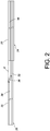
- FIG. 2 shows the third rail 26 comprising a first longitudinal portion 32, a second longitudinal portion 34, and a slant portion 36 connected between the first longitudinal portion 32 and the second longitudinal portion 34.
- the first longitudinal portion 32 of the third rail 26 is movably connected to the inside of the second rail 24, and the second longitudinal portion 34 of the third rail 26 extends from the slant portion 36 to be located outside the second rail 24.
- the second rail 24 comprises a longitudinally extending body 56 comprising a lateral side 25, and the second longitudinal portion 34 of the third rail 26 comprises a lateral side 35.
- the lateral side 35 of the second longitudinal portion 34 of the third rail 26 and the lateral side 25 of the longitudinally extending body 56 of the second rail 24 are substantially in a same reference plane X (the reference plane X is a fictitious plane, and the present invention is not limited thereto) by means of the slant portion 36.
- Each of the second rail 24 and the third rail 26 thereby may be mounted with a chassis, wherein the two chassis have substantially identical widths.
- the slant portion 36 of the third rail 26 may contact against the second rail 24 (as shown in FIG. 1 ).
- FIG. 3 shows the first rail 22 separated from the assembled second rail 24 and third rail 26.
- the first rail 22 comprises an upper wall 38, a lower wall 40, and a longitudinally extending body 42 extending between the upper wall 38 and the lower wall 40, wherein the upper wall 38, the lower wall 40, and the longitudinally extending body 42 collectively define a first longitudinal channel 23.
- the longitudinally extending body 42 of the first rail 22 comprises a guiding portion 78, and more particularly, the guiding portion 78 is integrated with the longitudinally extending body 42 of the first rail 22, but the present invention is not limited thereto.
- the guiding portion 78 comprises a horizontal section 80, an inclining section 82 extending from the horizontal section 80, and a blocking wall 84 adjacent to the inclining section 82.
- the longitudinally extending body 42 of the first rail 22 further comprises at least one fixing portion 43.
- the longitudinally extending body 42 of the first rail 22 comprises two fixing portions 43 which are holes (as in FIG. 3 ), but the present invention is not limited thereto.
- the slide rail assembly 20 further comprises a swinging member 86 and an assisting member 88, wherein the swinging member 86 is movably connected to the longitudinally extending body 42 of the first rail 22.
- the swinging member 86 is pivotally connected to the longitudinally extending body 42 of the first rail 22 by means of a first connection member 90.
- the swinging member 86 comprises a leg portion 92 and an extended side portion 94.
- the assisting member 88 is connected to the longitudinally extending body 42 of the first rail 22 and adjacent to the swinging member 86 and comprises a longitudinally extending elastic guiding portion 96, wherein the elastic guiding portion 96 of the assisting member 88 contacts the leg portion 92 of the swinging member 86.
- FIG. 4 shows the second rail 24 separated from the third rail 26.
- the second rail 24 is longitudinally and movably connected to the first rail 22, and more particularly, the second rail 24 is received in and movable along the first longitudinal channel 23 of the first rail 22.
- the second rail 24 comprises an upper wall 52, a lower wall 54, and a longitudinally extending body 56 extending between the upper wall 52 and the lower wall 54, wherein the upper wall 52, the lower wall 54, and the longitudinally extending body 56 collectively define a second longitudinal channel 29.
- the longitudinally extending body 56 of the second rail 24 comprises a first end portion 27a and a second end portion 27b opposite to the first end portion 27a.
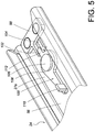
- the second rail 24 further comprises a protrusion portion 104 located at the longitudinally extending body 56.
- the slide rail assembly 20 further comprises a fixing member 98 and an actuating member 100 which are connected to the second rail 24. In a preferred embodiment, the fixing member 98 and the actuating member 100 are adjacent to the first end portion 27a of the second rail 24.
- the fixing member 98 comprises a contact section 102 corresponding in position to the protrusion portion 104 of the second rail 24.
- the actuating member 100 is movably connected to the longitudinally extending body 56 of the second rail 24.
- the actuating member 100 is rotatably connected to the longitudinally extending body 56 of the second rail 24 by means of a second connection member 106.
- the actuating member 100 comprises a main body 108, a contact portion 110, and a tail portion 112.
- the contact portion 110 may be, for example, a protrusion perpendicularly protruding from the main body 108 to contact and be guided by the guiding portion 78 of the longitudinally extending body 42 of the first rail 22, but the form of the contact portion 110 is not limited thereto.
- the tail portion 112 of the actuating member 100 longitudinally extends from the main body 108, but the present invention is not limited thereto.
- the tail portion 112 of the actuating member 100 is located between the contact section 102 of the fixing member 98 and the protrusion portion 104 of the second rail 24.
- one of the upper wall 52 and the lower wall 54 of the second rail 24 comprises an indention portion 114, wherein the indention portion 114 comprises a slant 116.
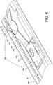
- the slide rail assembly 20 further comprises at least one restricting member 118 and a releasing member 120, wherein the restricting member 118 is attached to the second rail 24 and the releasing member 120 is mounted to the longitudinally extending body 56 of the second rail 24.
- the releasing member 120 is adjacent to the indention portion 114 of the second rail 24.
- the releasing member 120 comprises a moving portion 122 and a disengaging portion 124 extending from the moving portion 122.
- One of the moving portion 122 and the disengaging portion 124 comprises at least one longitudinal groove 126 corresponding to the at least one restricting member 118, an operating portion 128 connected to one of the moving portion 122 and the disengaging portion 124, and a flexible member 130 connected to one of the moving portion 122 and the disengaging portion 124.
- the at least one longitudinal groove 126 is disposed on the moving portion 122
- the operating portion 128 is connected to the moving portion 122
- the flexible member 130 is laterally connected to the moving portion 122, but the present invention is not limited thereto.
- the releasing member 120 is longitudinally movable with respect to the restricting member 118 when the operating portion 128 is longitudinally operated.
- the restricting member 118 is disposed within the longitudinal groove 126 so that the movement of the moving portion 122 can be stopped once either end of the longitudinal groove 126 contacts the restricting member 118 (as in FIG. 6 ).
- the disengaging portion 124 comprises at least one slant plate 132 and a flat plate 134 connected to the slant plate 132.
- the flat plate 134 comprises a disengaging edge 136.
- the longitudinally extending body 56 of the second rail 24 further comprises a blocking member 138, wherein a portion of the flexible member 130 can be correspondingly pressed against the blocking member 138.
- the flexible member 130 is an elongated plate extending from the moving portion 122 of the releasing member 120.
- the slide rail assembly 20 further comprises an engaging member 140 adjacent to the second end portion 27b of the second rail 24, wherein the engaging member 140 comprises at least one positioning portion 142.
- the positioning portion 142 may be a protruding post, but the present invention is not limited thereto; for example, the positioning portion 142 also may be other types of protrusion.
- the engaging member 140 comprises a base plate 144 and an elastic portion 146. The elastic portion 146 bends from the base plate 144 and thus is able to provide an elastic force.
- the base plate 144 may be mounted on the second rail 24 by means of at least one connection member 147, wherein the connection member 147 may be integrated on the second rail 24, but the present invention is not limited thereto; for example, the connection member 147 also may be an independent component mounted on the second rail 24.
- the positioning portion 142 is located adjacent to the elastic portion 146.
- the third rail 26 is longitudinally and movably connected to the second rail 24. More specifically, the third rail 26 is received in and movable along the second longitudinal channel 29 of the second rail 24.
- the third rail 26 comprises an upper wall 70 and a lower wall 72 in addition to the first longitudinal portion 32 and the second longitudinal portion 34, wherein the first longitudinal portion 32 and the second longitudinal portion 34 extend between the upper wall 70 and the lower wall 72.
- the first longitudinal portion 32 of the third rail 26 comprises a hook portion 148.
- the third rail 26 further comprises a guiding slant 150 adjacent to the hook portion 148, wherein the hook portion 148 is configured to engage with the contact portion 110 of the actuating member 100.
- the third rail 26 further comprises an opening 152.
- the opening 152 is located at the first longitudinal portion 32 of the third rail 26, but the present invention is not limited thereto.
- the operating member 30 is connected to the third rail 26.
- the operating member 30 comprises a base plate portion 31 connected to the second longitudinal portion 34 of the third rail 26, an elastic plate 33 bending from the base plate portion 31 and for providing an elastic force, and a handle portion 37 connected to the elastic plate 33.
- the elastic plate 33 comprises an engaging portion 39 corresponding to the fixing portion 43 of the first rail 22.
- the engaging portion 39 is a protrusion and the fixing portion 43 of the first rail 22 is a hole in the illustrative embodiment here; however, the fixing portion 43 of the first rail 22 may be a protrusion and the engaging portion 39 may be a hole in another embodiment not shown.
- the engaging portion 39 of the operating member 30 engages with the fixing portion 43 of the first rail 22 by the elastic force provided by the elastic plate 33;
- the elastic plate 33 may be slightly bent by means of the elasticity of the elastic plate 33 to disengage the engaging portion 39 from the fixing portion 43 of the first rail 22, thus allowing the user to move the third rail 26 along the extending direction by means of the handle portion 37 of the operating member 30.
- FIG. 9A to FIG. 13 are schematic views of the operation of the slide rail assembly 20.
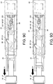
- the contact portion 110 of the actuating member 100 is guided by the horizontal section 80 of the guiding portion 78 and then moved upward along the inclining section 82 of the guiding portion 78; wherein when the contact portion 110 of the actuating member 100 is moved along the inclining section 82, the actuating member 100 rotates by an angle by means of the tail portion 112 pressing against the contact section 102 of the fixing member 98 (as in FIG. 9B ). Subsequently, the contact portion 110 of the actuating member 100 is moved to a distal edge of the inclining section 82 and thus lifted to disengage from the hook portion 148 of the third rail 26 (as in FIG. 9C ).
- At least one of the tail portion 112 of the actuating member 100 and the contact section 102 of the fixing member 98 is of flexible materials to facilitate rotation of the actuating member 100, thus allowing the contact portion 110 of the actuating member 100 to disengage from the hook portion 148 of the third rail 26 smoothly. Consequently, the contact portion 110 of the actuating member 100 is completely separated from the third rail 26 and blocked by the blocking wall 84 of the guiding portion 78 (as in FIG. 9D ) when the third rail 26 is further pulled along the extending direction D1.
- the leg portion 92 of the swinging member 86 is guided into the indention portion 114 of the second rail 24 (as in FIG. 9B ) and then pressed against the indention portion 114 of the second rail 24 (as in FIG. 9C ) in response to the elastic force generated by the elastic guiding portion 96 of the assisting member 88.
- the leg portion 92 of the swinging member 86 is engaged with the indention portion 114 of the second rail 24.
- the second rail 24 is positioned with respect to the first rail 22.
- the second rail 24 is no longer synchronously moved along with the third rail 26.
- the third rail 26 may continue to move along the extending direction D1.
- the elastic portion 146 of the engaging member 140 that is capable of bending elastically is pressed between the second rail 24 and the third rail 26 and is in an elastic force accumulation state (as in FIG. 10 and FIG. 12 ) before the third rail 26 moves to an extended position.
- the elastic portion 146 releases the elastic force so that the positioning portion 142 of the engaging member 140 enters the opening 152 of the first longitudinal portion 32 of the third rail 26 and is engaged with an opening edge 153 of the opening 152 (as in FIG. 11 and FIG. 13 ).
- the user may apply a force F1 from the opening 152 of the third rail 26 to the elastic portion 146 of the engaging member 140 (as in FIG. 16 ) so that the positioning portion 142 of the elastic portion 146 is separated from the opening 152 and no longer engages with the opening edge 153.
- the third rail 26 may be drawn in a dismounting direction D2 (as in FIG. 15 ) to dismount the third rail 26 from the second rail 24.
- the user may further dismount the second rail 24 from the first rail 22.
- the user may apply a force F2 (as in FIG. 17B ) to pull the operating portion 128 of the releasing member 120 so that the moving portion 122 of the releasing member 120 moves with respect to the restricting member 118 by means of the longitudinal groove 126.
- the disengaging portion 124 of the releasing member 120 is driven to move along with the moving portion 122 so that the disengaging edge 136 correspondingly presses against a portion of the swinging member 86 (such as the extended side portion 94) to disengage the leg portion 92 of the swinging member 86 from the indention portion 114 of the second rail 24 (meanwhile, the flexible member 130 is bent by the force applied from the blocking member 138).
- the second rail 24 may be drawn in a dismounting direction D3 to dismount the second rail 24 from the first rail 22 (as in FIG. 17C ).
- the flexible member 130 returns the releasing member 120 to its initial state (as in FIG. 17D ) once the user ceases applying the force F2 to the operating portion 128.
- the third rail 26 and the second rail 24 of the slide rail assembly 20 may both be dismounted so that the user may carry out replacement of the chassis (such as a server chassis) or replacement or maintenance of the slide rail assembly 20.
- the user may apply a force to press the elastic portion 146 of the engaging member 140 (as in FIG. 16 ) again and simultaneously push the third rail 26 along the retracting direction D4 so that the slant portion 36 of the third rail 26 may press against the second rail 24, thus allowing the third rail 26 and the second rail 24 to be retracted with respect to the first rail 22.
- the guiding slant 150 of the hook portion 148 of the third rail 26 correspondingly lifts the contact portion 110 of the actuating member 100 so that the contact portion 110 of the actuating member 100 is moved away from the blocking wall 84 and back to the distal edge of the inclining section 82 of the guiding portion 78 of the first rail 22 (as in FIG. 18B ). Furthermore, the slant 116 of the second rail 24 presses against the leg portion 92 of the swinging member 86 so that the leg portion 92 deviates and finally disengages from the indention portion 114 (as in FIG. 18C ).
- the contact portion 110 of the actuating member 100 may be guided by the guiding portion 78 of the first rail 22 again and moved back to engage with the hook portion 148 of the third rail 26, so that third rail 26 and the second rail 24 may be retracted to a retracted state with respect to the first rail 22 (as in FIG. 9A ).
Landscapes
- Engineering & Computer Science (AREA)
- Computer Hardware Design (AREA)
- General Engineering & Computer Science (AREA)
- Microelectronics & Electronic Packaging (AREA)
- Drawers Of Furniture (AREA)
Description
- The present invention relates to a slide rail assembly, and more particularly, to a slide rail assembly of which two rails may be synchronously moved and when one of the rails is moved to a position, the rail may be remained at the position while the other rail may be further moved forward.
- Generally speaking, a server chassis is mounted on a rack by means of a pair of slide rail assemblies in server systems. The slide rail assembly is usually in a form constituted by two or three sections of rails to carry the server chassis. The difference is that three-section rails have longer extension lengths to meet actual specific requirements.
- Among the technologies of three-section rails, the engagement between rails or the synchronous movement between rails along an extending direction has been common developed technologies, which also means that such related technologies have already become specific operational and commercial requirements. For example,
U.S. Pat. No. 7,413,269 B2 and6,997,529 B1 disclosed the engagement between engaging blocks and engaging holes (or engaging grooves) to ensure the positioning between rails and the synchronous movement. - The present invention is a slide rail assembly of which two rails may be synchronously moved and when one of the rails is moved to a position, the rail may be remained at the position while the other rail may be further moved forward.
- The present invention provides a slide rail assembly comprising a first rail, a second rail, an actuating member, and a third rail. The first rail comprises a guiding portion. The second rail is longitudinally and movably connected to the first rail. The actuating member is movably connected to the second rail and comprises a contact portion. The third rail is longitudinally and movably connected to the second rail and comprises a hook portion. When the third rail is pulled with respect to the first rail with the contact portion of the actuating member engaging with the hook portion of the third rail, the second rail is synchronously moved along with the third rail. When the second rail is moved to a predetermined position with respect to the first rail, the actuating member rotates by an angle by guiding means of the guiding portion of the first rail and thereby disengages the contact portion of the actuating member from the hook portion of the third rail.
- The guiding portion of the first rail comprises a horizontal section and an inclining section extending from the horizontal section. When the second rail is moved to the predetermined position with respect to the first rail, the actuating member is guided from the horizontal section to the inclining section and thereby rotates by the angle to disengage the contact portion of the actuating member from the hook portion of the third rail. Preferably, the guiding portion further comprises a blocking wall adjacent to the inclining section to further block the contact portion of the actuating member after the actuating member is guided from the horizontal section to the inclining section.
- The second rail comprises a protrusion portion and the slide rail assembly further comprises a fixing member connected to the second rail. The fixing member comprises a contact section corresponding to the protrusion portion of the second rail and the actuating member further comprises a tail portion located between the contact section of the fixing member and the protrusion portion of the second rail.
- The slide rail assembly further comprises a swinging member pivotally connected to the first rail and comprising a leg portion, wherein the second rail comprises an indention portion for the leg portion to press against; and an assisting member comprising an elastic guiding portion contacting the swinging member. When the second rail moves to the predetermined position, the swinging member presses the leg portion against the indention portion of the second rail by an elastic force generated by the elastic guiding portion.
- The second rail has a first end portion and a second end portion opposite to the first end portion. The fixing member and the actuating member are adjacent to the first end portion of the second rail. The slide rail assembly further comprises an engaging member adjacent to the second end portion of the second rail, wherein the engaging member comprises a positioning portion. The third rail further comprises an opening corresponding to the positioning portion of the engaging member so that the positioning portion of the engaging member engages with and positions at the opening of the third rail when the third rail moves with respect to the second rail to an extended position. The engaging member comprises a base plate and an elastic portion bending from the base plate, wherein the positioning portion is located at the elastic portion. The slide rail assembly further comprises at least one restricting member attached to the second rail; and a releasing member mounted to the second rail and comprising a moving portion and a disengaging portion, wherein one of the moving portion and the disengaging portion comprises at least one longitudinal groove interacting with the at least one restricting member, and wherein the disengaging portion interacts with a portion of the swinging member. When the releasing member is pulled with respect to the at least one restricting member after engagement of the leg portion of the swinging member with the indention portion of the second rail, the swinging member is moved by means of the disengaging portion of the releasing member to disengage the leg portion of the swinging member from the indention portion of the second rail.
- Another aspect of the present invention provides a slide rail assembly comprising a first rail, a second rail, a swinging member, and an assisting member. The second rail is longitudinally and movably connected to the first rail and comprises an indention portion. The swinging member is pivotally connected to the first rail and comprises a leg portion corresponding to the indention portion of the second rail. The assisting member is adjacent to the swinging member and comprises an elastic guiding portion contacting the swinging member. When the second rail moves to a predetermined position with respect to the first rail, the swinging member pivots in response to an elastic force generated by the elastic guiding portion to engage the leg portion of the swinging member with the indention portion of the second rail so that the second rail is positioned with respect to the first rail.
- Another aspect of the present invention provides a slide rail assembly comprising a first rail, a second rail, a fixing member, an actuating member, a third rail, and a swinging member. The first rail comprises an upper wall, a lower wall, and a longitudinally extending body extending between the upper wall and the lower wall of the first rail, wherein the longitudinally extending body comprises a guiding portion comprising a horizontal section, an inclining section extending from the horizontal section, and a blocking wall adjacent to the inclining section. The second rail is longitudinally and movably connected to the first rail and comprises an upper wall, a lower wall, a longitudinally extending body extending between the upper wall and the lower wall of the second rail, and a protrusion portion located at the longitudinally extending body of the second rail, wherein one of the upper wall and the lower wall comprises an indention portion. The fixing member is connected to the second rail and comprises a contact section corresponding to the protrusion portion of the second rail. The actuating member is movably connected to the second rail and comprises a contact portion corresponding to the guiding portion of the first rail and a tail portion located between the contact section of the fixing member and the protrusion portion of the second rail. The third rail is longitudinally and movably connected to the second rail and comprises a hook portion corresponding to the contact portion of the actuating member. When the third rail is moved along an extending direction with the contact portion of the actuating member correspondingly engaging with the hook portion of the third rail, the second rail is synchronously moved along with the third rail. When the second rail is moved to a position corresponding to the guiding portion of the first rail, the contact portion of the actuating member is successively guided by the horizontal section and the inclining section of the guiding portion of the first rail. When the contact portion of the actuating member is guided by the inclining section, the actuating member rotates by means of the tail portion pressing against the contact section of the fixing member so that the contact portion of the actuating member disengages from the hook portion of the third rail and is then guided to and blocked by the blocking wall of the guiding portion. The swinging member is movably connected to the longitudinally extending body of the first rail and comprises a leg portion corresponding to the indention portion of the second rail, wherein when the second rail is synchronously moved along with the third rail to a predetermined position along the extending direction, the leg portion of the swinging member enters the indention portion of the second rail.
- The second rail has a first end portion and a second end portion opposite to the first end portion. The fixing member and the actuating member are adjacent to the first end portion of the second rail. The slide rail assembly further comprises an engaging member adjacent to the second end portion of the second rail, wherein the engaging member comprises a positioning portion and the third rail further comprises an opening corresponding to the positioning portion of the engaging member so that the positioning portion of the engaging member engages with and positions at the opening of the third rail when the third rail moves with respect to the second rail to a position. The engaging member comprises a base plate and an elastic portion bending from the base plate, and wherein the positioning portion is located at the elastic portion.
- The slide rail assembly further comprises at least one restricting member attached to the second rail; and a releasing member mounted to the longitudinally extending body of the second rail and adjacent to the indention portion of the second rail. The releasing member comprises a moving portion and a disengaging portion, wherein one of the moving portion and the disengaging portion comprises at least one longitudinal groove corresponding to the at least one restricting member, and wherein the disengaging portion corresponds to a portion of the swinging member. When the moving portion is operated after engagement of the leg portion of the swinging member with the indention portion of the second rail, the disengaging portion is driven to move the portion of the swinging member so that the leg portion of the swinging member is disengaged from the indention portion of the second rail again.
- The third rail further comprises a guiding slant adjacent to the hook portion. When the third rail is retracted along a retracting direction, the contact portion of the actuating member is pressed back to engage with the hook portion of the third rail by the guiding slant of the third rail. The indention portion of the second rail comprises a slant. When the third rail is retracted along the retracting direction, the slant presses against the leg portion of the swinging member so that the leg portion deviates and leaves the indention portion of the second rail.
- The slide rail assembly further comprises an operating member connected to the third rail to be operated to move the third rail along the extending direction. The longitudinally extending body of the first rail comprises a fixing portion. The operating member comprises a base plate portion connected to the third rail, an elastic plate bending from the base plate portion for providing an elastic force, and a handle portion connected to the elastic plate. The elastic plate comprises an engaging portion corresponding to the fixing portion of the longitudinally extending body of the first rail. When the third rail is retracted to a retracted position with respect to the first rail, the engaging portion of the elastic plate engages with the fixing portion by the elastic force provided by the elastic plate.
- A feature of the invention is that when the third rail is moved along the extending direction, the second rail synchronously moves along with the third rail in the extending direction, and the second rail may temporarily remain at a position without moving along with the third rail when the position is arrived at, while the third rail may continue to move along the extending direction.
-
-
FIG. 1 shows a perspective view of a slide rail assembly in accordance with the present invention; -
FIG. 2 is a schematic view of the second rail and the third rail inFIG. 1 , wherein the second rail and the third rail are assemble to each other, and wherein the third rail is pulled from the second rail by a distance; -
FIG. 3 is a schematic exploded view of the first rail and the assembled second rail and third rail of the slide rail assembly in accordance with the present invention; -
FIG. 4 is a schematic exploded view of the second rail and the third rail of the slide rail assembly in accordance with the present invention; -
FIG. 5 is a detailed schematic view of a portion of the second rail of the slide rail assembly inFIG. 4 , showing the configuration between a fixing member, a protrusion portion, and an actuating member; -
FIG. 6 is a detailed schematic view of another portion of the second rail of the slide rail assembly inFIG. 4 , showing a releasing member mounted to the second rail and adjacent to an indention portion of the second rail; -
FIG. 7 is a detailed schematic view of still another portion of the second rail of the slide rail assembly inFIG. 4 , showing an engaging member mounted adjacent to a second end portion of the second rail; -
FIG. 8 is a detailed schematic view of a portion of the third rail of the slide rail assembly inFIG. 4 , showing a hook portion and a guiding slant; -
FIG. 9A schematically shows that the third rail of the slide rail assembly in accordance with the present invention engages with a contact portion of the actuating member by means of the hook portion; -
FIG. 9B schematically shows that the second rail of the slide rail assembly in accordance with the present invention is synchronously moved along with the third rail by means of the contact portion of the actuating member engaging with the hook portion; -
FIG. 9C schematically shows that the second rail of the slide rail assembly in accordance with the present invention is moved to a position and the contact portion of the actuating member is guided by a guiding portion of the first rail to disengage from the hook portion of the third rail; -
FIG. 9D schematically shows that the second rail of the slide rail assembly in accordance the present invention is moved to a predetermined position and the contact portion of the actuating member is blocked by a blocking wall of the guiding portion of the first rail; -
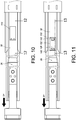
FIG. 10 schematically shows that the third rail of the slide rail assembly in accordance with the present invention is moved along an extending direction; -
FIG. 11 schematically shows that the third rail of the slide rail assembly in accordance with the present invention is further moved along the extending direction so that an opening of the third rail corresponds to the engaging member; -
FIG. 12 is a cross-section view taken along the line 12-12 ofFIG. 10 ; -
FIG. 13 is a cross-section view taken along the line 13-13 ofFIG. 11 ; -
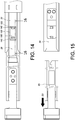
FIG. 14 schematically shows that the third rail of the slide rail assembly in accordance with the present invention is at an extended position; -
FIG. 15 schematically shows that the third rail of the slide rail assembly in accordance with the present invention is dismounted; -
FIG. 16 is a cross-section view taken along the line 16-16 ofFIG. 14 , showing that a force is applied to an elastic portion of the engaging member; -
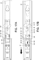
FIG. 17A schematically shows that the second rail of the slide rail assembly in accordance with the present invention is extended from the firs rail; -
FIG. 17B schematically shows that the releasing member of the slide rail assembly in accordance with the present invention is moved to disengage a leg portion of a swinging member from the indention portion of the second rail; -
FIG. 17C schematically shows that the second rail of the slide rail assembly in accordance with an embodiment of the present invention is dismounted from the first rail; -
FIG. 17D schematically shows that the second rail of the slide rail assembly in accordance with the present invention is dismounted from the first rail and a flexible member then moves the releasing member to return to the initial state; -
FIG. 18A schematically shows that the third rail of the slide rail assembly in accordance with the present invention is moved along a retracting direction and the guiding slant of the third rail lifts the contact portion of the actuating member; -
FIG. 18B schematically shows that the guiding slant of the third rail of the slide rail assembly in accordance with the present invention lifts and moves the contact portion of the actuating member away from the blocking wall of the guiding portion of the first rail; and -
FIG. 18C schematically shows that the third rail of the slide rail assembly in accordance with the present invention is further moved along the retracting direction and the leg portion of the swinging member is thereby driven to leave the indention portion of the second rail by the slant. -
FIG. 1 shows aslide rail assembly 20 comprising afirst rail 22, asecond rail 24, and athird rail 26 at a retracted state according to an embodiment of the present invention. Thesecond rail 24 and thethird rail 26 may be longitudinally moved with respect to thefirst rail 22. Preferably, thesecond rail 24 and thethird rail 26 each comprises at least one mountingportion 28 for mounting a chassis (such as a server chassis). Preferably, an operatingmember 30 is connected to thethird rail 26 and configured to be operated to move thethird rail 26 along an extending direction. - Referring to
FIG. 1 andFIG. 2, FIG. 2 shows thethird rail 26 comprising a firstlongitudinal portion 32, a secondlongitudinal portion 34, and aslant portion 36 connected between the firstlongitudinal portion 32 and the secondlongitudinal portion 34. The firstlongitudinal portion 32 of thethird rail 26 is movably connected to the inside of thesecond rail 24, and the secondlongitudinal portion 34 of thethird rail 26 extends from theslant portion 36 to be located outside thesecond rail 24. - As shown in
FIG. 2 , thesecond rail 24 comprises alongitudinally extending body 56 comprising alateral side 25, and the secondlongitudinal portion 34 of thethird rail 26 comprises alateral side 35. Thelateral side 35 of the secondlongitudinal portion 34 of thethird rail 26 and thelateral side 25 of thelongitudinally extending body 56 of thesecond rail 24 are substantially in a same reference plane X (the reference plane X is a fictitious plane, and the present invention is not limited thereto) by means of theslant portion 36. Each of thesecond rail 24 and thethird rail 26 thereby may be mounted with a chassis, wherein the two chassis have substantially identical widths. In addition, theslant portion 36 of thethird rail 26 may contact against the second rail 24 (as shown inFIG. 1 ). -
FIG. 3 shows thefirst rail 22 separated from the assembledsecond rail 24 andthird rail 26. - The
first rail 22 comprises anupper wall 38, alower wall 40, and alongitudinally extending body 42 extending between theupper wall 38 and thelower wall 40, wherein theupper wall 38, thelower wall 40, and thelongitudinally extending body 42 collectively define a firstlongitudinal channel 23. Thelongitudinally extending body 42 of thefirst rail 22 comprises a guidingportion 78, and more particularly, the guidingportion 78 is integrated with thelongitudinally extending body 42 of thefirst rail 22, but the present invention is not limited thereto. The guidingportion 78 comprises ahorizontal section 80, aninclining section 82 extending from thehorizontal section 80, and a blockingwall 84 adjacent to theinclining section 82. Moreover, thelongitudinally extending body 42 of thefirst rail 22 further comprises at least one fixingportion 43. In a preferred embodiment, thelongitudinally extending body 42 of thefirst rail 22 comprises two fixingportions 43 which are holes (as inFIG. 3 ), but the present invention is not limited thereto. - The
slide rail assembly 20 further comprises a swingingmember 86 and an assistingmember 88, wherein the swingingmember 86 is movably connected to thelongitudinally extending body 42 of thefirst rail 22. Preferably, the swingingmember 86 is pivotally connected to thelongitudinally extending body 42 of thefirst rail 22 by means of afirst connection member 90. The swingingmember 86 comprises aleg portion 92 and anextended side portion 94. The assistingmember 88 is connected to thelongitudinally extending body 42 of thefirst rail 22 and adjacent to the swingingmember 86 and comprises a longitudinally extending elastic guidingportion 96, wherein the elastic guidingportion 96 of the assistingmember 88 contacts theleg portion 92 of the swingingmember 86. - Referring to
FIG. 3 andFIG. 4, FIG. 4 shows thesecond rail 24 separated from thethird rail 26. - The
second rail 24 is longitudinally and movably connected to thefirst rail 22, and more particularly, thesecond rail 24 is received in and movable along the firstlongitudinal channel 23 of thefirst rail 22. Thesecond rail 24 comprises anupper wall 52, alower wall 54, and alongitudinally extending body 56 extending between theupper wall 52 and thelower wall 54, wherein theupper wall 52, thelower wall 54, and thelongitudinally extending body 56 collectively define a secondlongitudinal channel 29. Thelongitudinally extending body 56 of thesecond rail 24 comprises afirst end portion 27a and asecond end portion 27b opposite to thefirst end portion 27a. Thesecond rail 24 further comprises aprotrusion portion 104 located at thelongitudinally extending body 56. Theslide rail assembly 20 further comprises a fixingmember 98 and anactuating member 100 which are connected to thesecond rail 24. In a preferred embodiment, the fixingmember 98 and the actuatingmember 100 are adjacent to thefirst end portion 27a of thesecond rail 24. - As shown in
FIG. 5 , the fixingmember 98 comprises acontact section 102 corresponding in position to theprotrusion portion 104 of thesecond rail 24. The actuatingmember 100 is movably connected to thelongitudinally extending body 56 of thesecond rail 24. Preferably, the actuatingmember 100 is rotatably connected to thelongitudinally extending body 56 of thesecond rail 24 by means of asecond connection member 106. The actuatingmember 100 comprises amain body 108, acontact portion 110, and atail portion 112. - The
contact portion 110 may be, for example, a protrusion perpendicularly protruding from themain body 108 to contact and be guided by the guidingportion 78 of thelongitudinally extending body 42 of thefirst rail 22, but the form of thecontact portion 110 is not limited thereto. Preferably, thetail portion 112 of the actuatingmember 100 longitudinally extends from themain body 108, but the present invention is not limited thereto. Thetail portion 112 of the actuatingmember 100 is located between thecontact section 102 of the fixingmember 98 and theprotrusion portion 104 of thesecond rail 24. In addition, one of theupper wall 52 and thelower wall 54 of thesecond rail 24 comprises anindention portion 114, wherein theindention portion 114 comprises aslant 116. - As shown in
FIG. 4 andFIG. 6 , theslide rail assembly 20 further comprises at least one restrictingmember 118 and a releasingmember 120, wherein the restrictingmember 118 is attached to thesecond rail 24 and the releasingmember 120 is mounted to thelongitudinally extending body 56 of thesecond rail 24. The releasingmember 120 is adjacent to theindention portion 114 of thesecond rail 24. - The releasing
member 120 comprises a movingportion 122 and a disengagingportion 124 extending from the movingportion 122. One of the movingportion 122 and the disengagingportion 124 comprises at least onelongitudinal groove 126 corresponding to the at least one restrictingmember 118, an operatingportion 128 connected to one of the movingportion 122 and the disengagingportion 124, and aflexible member 130 connected to one of the movingportion 122 and the disengagingportion 124. In a preferred embodiment, the at least onelongitudinal groove 126 is disposed on the movingportion 122, the operatingportion 128 is connected to the movingportion 122, and theflexible member 130 is laterally connected to the movingportion 122, but the present invention is not limited thereto. Moreover, by means of the structural configuration of the restrictingmember 118 and thelongitudinal groove 126, the releasingmember 120 is longitudinally movable with respect to the restrictingmember 118 when the operatingportion 128 is longitudinally operated. Preferably, the restrictingmember 118 is disposed within thelongitudinal groove 126 so that the movement of the movingportion 122 can be stopped once either end of thelongitudinal groove 126 contacts the restricting member 118 (as inFIG. 6 ). - The disengaging
portion 124 comprises at least oneslant plate 132 and aflat plate 134 connected to theslant plate 132. In a preferred embodiment, there are twoslant plates 132 and theflat plate 134 is connected between the twoslant plates 132, wherein one of the twoslant plates 132 is connected to the movingportion 122 and bends from the movingportion 122 by an angle, but the present invention is not limited thereto. Theflat plate 134 comprises a disengagingedge 136. Thelongitudinally extending body 56 of thesecond rail 24 further comprises a blockingmember 138, wherein a portion of theflexible member 130 can be correspondingly pressed against the blockingmember 138. In more detail, theflexible member 130 is an elongated plate extending from the movingportion 122 of the releasingmember 120. - As shown in
FIG. 4 andFIG. 7 , theslide rail assembly 20 further comprises an engagingmember 140 adjacent to thesecond end portion 27b of thesecond rail 24, wherein the engagingmember 140 comprises at least onepositioning portion 142. It is noted that thepositioning portion 142 may be a protruding post, but the present invention is not limited thereto; for example, thepositioning portion 142 also may be other types of protrusion. Preferably, there are two positioningportions 142. Moreover, in a preferred embodiment, the engagingmember 140 comprises abase plate 144 and anelastic portion 146. Theelastic portion 146 bends from thebase plate 144 and thus is able to provide an elastic force. Thebase plate 144 may be mounted on thesecond rail 24 by means of at least oneconnection member 147, wherein theconnection member 147 may be integrated on thesecond rail 24, but the present invention is not limited thereto; for example, theconnection member 147 also may be an independent component mounted on thesecond rail 24. Thepositioning portion 142 is located adjacent to theelastic portion 146. - As shown in
FIG. 4 andFIG. 8 , thethird rail 26 is longitudinally and movably connected to thesecond rail 24. More specifically, thethird rail 26 is received in and movable along the secondlongitudinal channel 29 of thesecond rail 24. Thethird rail 26 comprises an upper wall 70 and a lower wall 72 in addition to the firstlongitudinal portion 32 and the secondlongitudinal portion 34, wherein the firstlongitudinal portion 32 and the secondlongitudinal portion 34 extend between the upper wall 70 and the lower wall 72. - The first
longitudinal portion 32 of thethird rail 26 comprises ahook portion 148. In a preferred embodiment, thethird rail 26 further comprises a guidingslant 150 adjacent to thehook portion 148, wherein thehook portion 148 is configured to engage with thecontact portion 110 of the actuatingmember 100. Thethird rail 26 further comprises anopening 152. In a preferred embodiment, theopening 152 is located at the firstlongitudinal portion 32 of thethird rail 26, but the present invention is not limited thereto. - In addition, as shown in
FIG. 3 andFIG. 4 , the operatingmember 30 is connected to thethird rail 26. In a preferred embodiment, the operatingmember 30 comprises abase plate portion 31 connected to the secondlongitudinal portion 34 of thethird rail 26, anelastic plate 33 bending from thebase plate portion 31 and for providing an elastic force, and ahandle portion 37 connected to theelastic plate 33. Theelastic plate 33 comprises an engagingportion 39 corresponding to the fixingportion 43 of thefirst rail 22. The engagingportion 39 is a protrusion and the fixingportion 43 of thefirst rail 22 is a hole in the illustrative embodiment here; however, the fixingportion 43 of thefirst rail 22 may be a protrusion and the engagingportion 39 may be a hole in another embodiment not shown. Accordingly, when thethird rail 26 is retracted back to a retracted position with respect to the first rail 22 (as inFIG. 1 ), the engagingportion 39 of the operatingmember 30 engages with the fixingportion 43 of thefirst rail 22 by the elastic force provided by theelastic plate 33; on the other hand, when the user wishes to move thethird rail 26 along the extending direction, theelastic plate 33 may be slightly bent by means of the elasticity of theelastic plate 33 to disengage the engagingportion 39 from the fixingportion 43 of thefirst rail 22, thus allowing the user to move thethird rail 26 along the extending direction by means of thehandle portion 37 of the operatingmember 30. -
FIG. 9A to FIG. 13 are schematic views of the operation of theslide rail assembly 20. - As shown in
FIG. 9A to FIG. 9D , when the user pulls thethird rail 26, by means of thehandle portion 37 of the operatingmember 30, along an extending direction D1 with respect to thefirst rail 22 with thecontact portion 110 of the actuatingmember 100 correspondingly engaging with thehook portion 148 of the third rail 26 (as inFIG. 9A and 9B ), thesecond rail 24 is synchronously moved along with thethird rail 26; however, when thesecond rail 24 is moved to a predetermined position with respect to thefirst rail 22, thecontact portion 110 of the actuatingmember 100 is correspondingly guided by the guidingportion 78 of thefirst rail 22 and finally disengaged from thehook portion 148 of the third rail 26 (as inFIG. 9C and 9D ). Specifically, thecontact portion 110 of the actuatingmember 100 is guided by thehorizontal section 80 of the guidingportion 78 and then moved upward along the incliningsection 82 of the guidingportion 78; wherein when thecontact portion 110 of the actuatingmember 100 is moved along the incliningsection 82, the actuatingmember 100 rotates by an angle by means of thetail portion 112 pressing against thecontact section 102 of the fixing member 98 (as inFIG. 9B ). Subsequently, thecontact portion 110 of the actuatingmember 100 is moved to a distal edge of theinclining section 82 and thus lifted to disengage from thehook portion 148 of the third rail 26 (as inFIG. 9C ). Preferably, at least one of thetail portion 112 of the actuatingmember 100 and thecontact section 102 of the fixingmember 98 is of flexible materials to facilitate rotation of the actuatingmember 100, thus allowing thecontact portion 110 of the actuatingmember 100 to disengage from thehook portion 148 of thethird rail 26 smoothly. Consequently, thecontact portion 110 of the actuatingmember 100 is completely separated from thethird rail 26 and blocked by the blockingwall 84 of the guiding portion 78 (as inFIG. 9D ) when thethird rail 26 is further pulled along the extending direction D1. - Moreover, as shown in
FIG. 9B andFIG. 9C , theleg portion 92 of the swingingmember 86 is guided into theindention portion 114 of the second rail 24 (as inFIG. 9B ) and then pressed against theindention portion 114 of the second rail 24 (as inFIG. 9C ) in response to the elastic force generated by the elastic guidingportion 96 of the assistingmember 88. In other words, theleg portion 92 of the swingingmember 86 is engaged with theindention portion 114 of thesecond rail 24. As such, thesecond rail 24 is positioned with respect to thefirst rail 22. - As shown in
FIG. 9D , as thecontact portion 110 of the actuatingmember 100 is blocked by the blockingwall 84 of the guidingportion 78 of thefirst rail 22 and theleg portion 92 of the swingingmember 86 is engaged with theindention portion 114 of thesecond rail 24, thesecond rail 24 is no longer synchronously moved along with thethird rail 26. However, thethird rail 26 may continue to move along the extending direction D1. - As shown in
FIG. 10 to FIG. 13 , as thethird rail 26 continues to move along the extending direction D1, theelastic portion 146 of the engagingmember 140 that is capable of bending elastically is pressed between thesecond rail 24 and thethird rail 26 and is in an elastic force accumulation state (as inFIG. 10 andFIG. 12 ) before thethird rail 26 moves to an extended position. Once thethird rail 26 further moves to the extended position, theelastic portion 146 releases the elastic force so that thepositioning portion 142 of the engagingmember 140 enters theopening 152 of the firstlongitudinal portion 32 of thethird rail 26 and is engaged with anopening edge 153 of the opening 152 (as inFIG. 11 andFIG. 13 ). - As shown in
FIG. 14 to FIG. 16 , to dismount thethird rail 26 from thesecond rail 24 when thethird rail 26 is at the extended position, the user may apply a force F1 from theopening 152 of thethird rail 26 to theelastic portion 146 of the engaging member 140 (as inFIG. 16 ) so that thepositioning portion 142 of theelastic portion 146 is separated from theopening 152 and no longer engages with the openingedge 153. As such, thethird rail 26 may be drawn in a dismounting direction D2 (as inFIG. 15 ) to dismount thethird rail 26 from thesecond rail 24. - As shown in
FIG. 17A to FIG. 17D , after thethird rail 26 is dismounted, the user may further dismount thesecond rail 24 from thefirst rail 22. The user may apply a force F2 (as inFIG. 17B ) to pull the operatingportion 128 of the releasingmember 120 so that the movingportion 122 of the releasingmember 120 moves with respect to the restrictingmember 118 by means of thelongitudinal groove 126. As such, the disengagingportion 124 of the releasingmember 120 is driven to move along with the movingportion 122 so that the disengagingedge 136 correspondingly presses against a portion of the swinging member 86 (such as the extended side portion 94) to disengage theleg portion 92 of the swingingmember 86 from theindention portion 114 of the second rail 24 (meanwhile, theflexible member 130 is bent by the force applied from the blocking member 138). As such, thesecond rail 24 may be drawn in a dismounting direction D3 to dismount thesecond rail 24 from the first rail 22 (as inFIG. 17C ). Theflexible member 130 returns the releasingmember 120 to its initial state (as inFIG. 17D ) once the user ceases applying the force F2 to the operatingportion 128. - As illustrated in
FIG. 14 to FIG. 17D , thethird rail 26 and thesecond rail 24 of theslide rail assembly 20 may both be dismounted so that the user may carry out replacement of the chassis (such as a server chassis) or replacement or maintenance of theslide rail assembly 20. - Moreover, as shown in
FIG. 18A to FIG. 18C , to retract thethird rail 26 from the extended position (as inFIG. 11 ) along a retracting direction D4, the user may apply a force to press theelastic portion 146 of the engaging member 140 (as inFIG. 16 ) again and simultaneously push thethird rail 26 along the retracting direction D4 so that theslant portion 36 of thethird rail 26 may press against thesecond rail 24, thus allowing thethird rail 26 and thesecond rail 24 to be retracted with respect to thefirst rail 22. When thesecond rail 24 is moved to a position, the guidingslant 150 of thehook portion 148 of thethird rail 26 correspondingly lifts thecontact portion 110 of the actuatingmember 100 so that thecontact portion 110 of the actuatingmember 100 is moved away from the blockingwall 84 and back to the distal edge of theinclining section 82 of the guidingportion 78 of the first rail 22 (as inFIG. 18B ). Furthermore, theslant 116 of thesecond rail 24 presses against theleg portion 92 of the swingingmember 86 so that theleg portion 92 deviates and finally disengages from the indention portion 114 (as inFIG. 18C ). As such, thecontact portion 110 of the actuatingmember 100 may be guided by the guidingportion 78 of thefirst rail 22 again and moved back to engage with thehook portion 148 of thethird rail 26, so thatthird rail 26 and thesecond rail 24 may be retracted to a retracted state with respect to the first rail 22 (as inFIG. 9A ). - While the invention has been described by way of example and in terms of the preferred embodiments, it is to be understood that the invention defined by the appended claims is not limited to the disclosed embodiments.
Claims (13)
- A slide rail assembly (20), comprising:a first rail (22), comprising a guiding portion (78); anda second rail (24), longitudinally and movably connected to the first rail (22);an actuating member (100), movably connected to the second rail (24) and comprising a contact portion (110); anda third rail (26), longitudinally and movably connected to the second rail (24) and comprising a hook portion (148),wherein when the third rail (26) is pulled with respect to the first rail (22) along an extending direction with the contact portion (110) of the actuating member (100) engaging with the hook portion (148) of the third rail (26), the second rail (24) is synchronously moved along with the third rail (26), and wherein when the second rail (24) is moved along the extending direction to a predetermined position with respect to the first rail (22), the actuating member (100) rotates by an angle by guiding means of the guiding portion (78) of the first rail (22) and thereby disengages the contact portion (110) of the actuating member (100) from the hook portion (148) of the third rail (26), characterized in that the guiding portion (78) of the first rail (22) comprises a horizontal section (80) and an inclining section (82) extending from the horizontal section (80), and wherein when the second rail (24) is moved to the predetermined position with respect to the first rail (22), the actuating member (100) is guided from the horizontal section (80) to the inclining section (82) and thereby rotates by the angle to disengage the contact portion (110) of the actuating member (100) from the hook portion (148) of the third rail (26).
- The slide rail assembly (20) as claimed in claim 1, wherein the guiding portion (78) further comprises a blocking wall (84) adjacent to the inclining section (82) to further block the contact portion (110) of the actuating member (100) after the actuating member (100) is guided from the horizontal section (80) to the inclining section (82).
- The slide rail assembly (20) as claimed in claim 1, wherein the second rail (24) comprises a protrusion portion (104) and the slide rail assembly (20) further comprises a fixing member (98) connected to the second rail (24), and wherein the fixing member (98) comprises a contact section (102) corresponding to the protrusion portion (104) of the second rail (24) and the actuating member (100) further comprises a tail portion (112) located between the contact section (102) of the fixing member (98) and the protrusion portion (104) of the second rail (24).
- The slide rail assembly (20) as claimed in claim 1, further comprising:a swinging member (86), pivotally connected to the first rail (22) and comprising a leg portion (92), wherein the second rail (24) comprises an indention portion (114) for the leg portion (92) to engage with; andan assisting member (88), comprising an elastic guiding portion (96) contacting the swinging member (86),wherein when the second rail (24) moves to the predetermined position, the swinging member (86) presses the leg portion (92) against the indention portion (114) of the second rail (24) by an elastic force generated by the elastic guiding portion (96).
- The slide rail assembly (20) as claimed in claim 4, further comprising:at least one restricting member (118), attached to the second rail (24); anda releasing member (120), mounted to the second rail (24) and comprising a moving portion (122) and a disengaging portion (124), wherein one of the moving portion (122) and the disengaging portion (124) comprises at least one longitudinal groove (126) interacting with the at least one restricting member (118), and wherein the disengaging portion (124) interacts with a portion of the swinging member (86),wherein when the releasing member (120) is pulled with respect to the at least one restricting member (118) after engagement of the leg portion (92) of the swinging member (86) with the indention portion (114) of the second rail (24), the swinging member (86) is moved by means of the disengaging portion (124) of the releasing member (120) to disengage the leg portion (92) of the swinging member (86) from the indention portion (114) of the second rail (24).
- The slide rail assembly (20) as claimed in claim 1, further comprising:a fixing member (98), connected to the second rail (24) and comprising a contact section (102), anda swinging member (86), movably connected to the longitudinally extending body (42) of the first rail (22) and comprising a leg portion (92),wherein the first rail (22) comprises an upper wall (38), a lower wall (40), and a longitudinally extending body (42) extending between the upper wall (38) and the lower wall (40) of the first rail (22), wherein the guiding portion (78) is configured on the longitudinally extending body (42) of the first rail (22) and further comprises a blocking wall (84) adjacent to the inclining section (82);
wherein the second rail (24) comprises an upper wall (52), a lower wall (54), a longitudinally extending body (56) extending between the upper wall (52) and the lower wall (54) of the second rail (24), and a protrusion portion (104) located at the longitudinally extending body (56) of the second rail (24) and corresponding to the contact section (102) of the fixing member (98), wherein one of the upper wall (52) and the lower wall (54) of the second rail (24) comprises an indention portion (114) corresponding to the leg portion (92) of the swinging member (86);
wherein the actuating member (100) further comprises a tail portion (112), wherein the contact portion (110) of the actuating member (100) corresponds in configuration to the guiding portion (78) of the first rail (22) and the hook portion (148) of the third rail (26), and wherein the tail portion (112) of the actuating member (100) is located between the contact section (102) of the fixing member (98) and the protrusion portion (104) of the second rail (24);
wherein when the second rail (24) is moved to a position corresponding to the guiding portion (78) of the first rail (22), the contact portion (110) of the actuating member (100) is successively guided by the horizontal section (80) and the inclining section (82) of the guiding portion (78) of the first rail (22), and wherein when the contact portion (110) of the actuating member (100) is guided by the inclining section (82), the actuating member (100) rotates by means of the tail portion (112) pressing against the contact section (102) of the fixing member (98) so that the contact portion (110) of the actuating member (100) disengages from the hook portion (148) of the third rail (26) and is then guided to and blocked by the blocking wall (84) of the guiding portion (78); and
wherein when the second rail (24) is synchronously moved along with the third rail (26) to the predetermined position along the extending direction, the leg portion (92) of the swinging member (86) enters the indention portion (114) of the second rail (24). - The slide rail assembly (20) as claimed in claim 3 or 6, wherein the second rail (24) has a first end portion (27a), and wherein the fixing member (98) and the actuating member (100) are adjacent to the first end portion (27a) of the second rail (24).
- The slide rail assembly (20) as claimed in claim 3 or 6, wherein the second rail (24) has a second end portion (27b) and the slide rail assembly (20) further comprises an engaging member (140) adjacent to the second end portion (27b) of the second rail (24), and wherein the engaging member (140) comprises a positioning portion (142) and the third rail (26) further comprises an opening (152) corresponding to the positioning portion (142) of the engaging member (140) so that the positioning portion (142) of the engaging member (140) engages with and positions at the opening (152) of the third rail (26) when the third rail (26) moves with respect to the second rail (24) to an extended position.
- The slide rail assembly (20) as claimed in claim 8, wherein the engaging member (140) comprises a base plate (144) and an elastic portion (146) bending from the base plate (144), and wherein the positioning portion (142) is located at the elastic portion (146).
- The slide rail assembly (20) as claimed in claim 6, further comprising:at least one restricting member (118), attached to the second rail (24); anda releasing member (120), mounted to the longitudinally extending body (56) of the second rail (24) and adjacent to the indention portion (114) of the second rail (24), the releasing member (120) comprising a moving portion (122) and a disengaging portion (124), wherein one of the moving portion (122) and the disengaging portion (124) comprises at least one longitudinal groove (126) corresponding to the at least one restricting member (118), and wherein the disengaging portion (124) corresponds to a portion of the swinging member (86),wherein when the moving portion (122) is operated after engagement of the leg portion (92) of the swinging member (86) with the indention portion (114) of the second rail (24), the disengaging portion (124) is driven to move the portion of the swinging member (86) so that the leg portion (92) of the swinging member (86) is disengaged from the indention portion (114) of the second rail (24) again.
- The slide rail assembly (20) as claimed in claim 6, wherein the third rail (26) further comprises a guiding slant (150) adjacent to the hook portion (148), and wherein when the third rail (26) is retracted along a retracting direction, the contact portion (110) of the actuating member (100) is pressed back to engage with the hook portion (148) of the third rail (26) by the guiding slant (150) of the third rail (26).
- The slide rail assembly (20) as claimed in claim 11, wherein the indention portion (114) of the second rail (24) comprises a slant (116), and wherein when the third rail (26) is retracted along the retracting direction, the slant (116) presses against the leg portion (92) of the swinging member (86) so that the leg portion (92) deviates and leaves the indention portion (114) of the second rail (24).
- The slide rail assembly (20) as claimed in claim 6, further comprising an operating member (30) connected to the third rail (26) to be operated to move the third rail (26) along the extending direction, wherein the longitudinally extending body (42) of the first rail (22) comprises a fixing portion (43), wherein the operating member (30) comprises a base plate portion (31) connected to the third rail (26), an elastic plate (33) bending from the base plate portion (31) for providing an elastic force, and a handle portion (37) connected to the elastic plate (33), wherein the elastic plate (33) comprises an engaging portion (39) corresponding to the fixing portion (43) of the longitudinally extending body (42) of the first rail (22), and wherein when the third rail (26) is retracted to a retracted position with respect to the first rail (22), the engaging portion (39) of the elastic plate (33) engages with the fixing portion (43) by the elastic force provided by the elastic plate (33).
Priority Applications (1)
| Application Number | Priority Date | Filing Date | Title |
|---|---|---|---|
| EP14182876.4A EP2989930B1 (en) | 2014-08-29 | 2014-08-29 | Slide rail assembly |
Applications Claiming Priority (1)
| Application Number | Priority Date | Filing Date | Title |
|---|---|---|---|
| EP14182876.4A EP2989930B1 (en) | 2014-08-29 | 2014-08-29 | Slide rail assembly |
Publications (2)
| Publication Number | Publication Date |
|---|---|
| EP2989930A1 EP2989930A1 (en) | 2016-03-02 |
| EP2989930B1 true EP2989930B1 (en) | 2017-12-06 |
Family
ID=51417220
Family Applications (1)
| Application Number | Title | Priority Date | Filing Date |
|---|---|---|---|
| EP14182876.4A Active EP2989930B1 (en) | 2014-08-29 | 2014-08-29 | Slide rail assembly |
Country Status (1)
| Country | Link |
|---|---|
| EP (1) | EP2989930B1 (en) |
Cited By (1)
| Publication number | Priority date | Publication date | Assignee | Title |
|---|---|---|---|---|
| TWI653953B (en) | 2018-03-26 | 2019-03-21 | 川湖科技股份有限公司 | Slide rail assembly |
Families Citing this family (7)
| Publication number | Priority date | Publication date | Assignee | Title |
|---|---|---|---|---|
| EP3041328B1 (en) * | 2014-12-30 | 2019-10-23 | King Slide Works Co., Ltd. | Slide rail assembly |
| US10213017B2 (en) | 2016-10-05 | 2019-02-26 | King Slide Works Co., Ltd. | Slide rail assembly |
| TWI606776B (en) * | 2016-10-05 | 2017-11-21 | 川湖科技股份有限公司 | Slide rail assembly |
| TWI620535B (en) * | 2016-10-05 | 2018-04-11 | 川湖科技股份有限公司 | Slide rail assembly |
| TWI665983B (en) * | 2017-04-12 | 2019-07-21 | 川湖科技股份有限公司 | Slide rail assembly |
| TWI659710B (en) * | 2018-04-02 | 2019-05-21 | 川湖科技股份有限公司 | Slide rail assembly |
| TWI693042B (en) | 2018-07-19 | 2020-05-11 | 川湖科技股份有限公司 | Slide rail mechanism and bracket device thereof |
Family Cites Families (2)
| Publication number | Priority date | Publication date | Assignee | Title |
|---|---|---|---|---|
| US7413269B2 (en) | 2004-08-04 | 2008-08-19 | King Slide Works Co., Ltd. | Synchronous system for a three-stage ball bearing slide |
| US6997529B1 (en) | 2005-01-19 | 2006-02-14 | King Slide Works Co., Ltd. | Synchronizing device for a tri-sector slide |
-
2014
- 2014-08-29 EP EP14182876.4A patent/EP2989930B1/en active Active
Non-Patent Citations (1)
| Title |
|---|
| None * |
Cited By (1)
| Publication number | Priority date | Publication date | Assignee | Title |
|---|---|---|---|---|
| TWI653953B (en) | 2018-03-26 | 2019-03-21 | 川湖科技股份有限公司 | Slide rail assembly |
Also Published As
| Publication number | Publication date |
|---|---|
| EP2989930A1 (en) | 2016-03-02 |
Similar Documents
| Publication | Publication Date | Title |
|---|---|---|
| US9279280B1 (en) | Slide rail assembly | |
| EP2989930B1 (en) | Slide rail assembly | |
| US9480183B2 (en) | Slide rail assembly | |
| US10244868B2 (en) | Slide rail assembly | |
| US8240789B2 (en) | Positioning device for slide assembly | |
| EP3195760B1 (en) | Slide rail assembly and operation method thereof | |
| US6926377B2 (en) | Drawer slide latch and release mechanism | |
| US10342341B2 (en) | Slide rail assembly | |
| US6997529B1 (en) | Synchronizing device for a tri-sector slide | |
| US20130058596A1 (en) | Slide assembly with positioning device | |
| EP3387950B1 (en) | Slide rail assembly | |
| US10398228B2 (en) | Slide rail assembly | |
| EP3094166B1 (en) | Slide rail assembly | |
| US9237806B2 (en) | Sliding track assembly | |
| TW202045068A (en) | Slide rail assembly and operation method thereof | |
| EP3440961B1 (en) | Slide rail assembly and rail kit thereof | |
| EP3225132A1 (en) | Driving mechanism and driving method for furniture parts | |
| EP3041328B1 (en) | Slide rail assembly | |
| EP3808215B1 (en) | Slide rail assembly | |
| US9211003B1 (en) | Slide rail assembly | |
| EP3289923B1 (en) | Retracting mechanism for a movable furniture part | |
| CN203553697U (en) | Interlocking mechanism of grounding switch and mobile handcart | |
| US8619032B2 (en) | Mouse structure with retracting function | |
| EP2979582B1 (en) | Slide rail assembly | |
| TWI543731B (en) | Slide rail assembly |
Legal Events
| Date | Code | Title | Description |
|---|---|---|---|
| PUAI | Public reference made under article 153(3) epc to a published international application that has entered the european phase |
Free format text: ORIGINAL CODE: 0009012 |
|
| 17P | Request for examination filed |
Effective date: 20151028 |
|
| AK | Designated contracting states |
Kind code of ref document: A1 Designated state(s): AL AT BE BG CH CY CZ DE DK EE ES FI FR GB GR HR HU IE IS IT LI LT LU LV MC MK MT NL NO PL PT RO RS SE SI SK SM TR |
|
| AX | Request for extension of the european patent |
Extension state: BA ME |
|
| REG | Reference to a national code |
Ref country code: DE Ref legal event code: R079 Ref document number: 602014018107 Country of ref document: DE Free format text: PREVIOUS MAIN CLASS: A47B0088100000 Ipc: A47B0088493000 |
|
| RIC1 | Information provided on ipc code assigned before grant |
Ipc: A47B 88/493 20170101AFI20170518BHEP Ipc: H05K 7/14 20060101ALI20170518BHEP |
|
| GRAP | Despatch of communication of intention to grant a patent |
Free format text: ORIGINAL CODE: EPIDOSNIGR1 |
|
| INTG | Intention to grant announced |
Effective date: 20170706 |
|
| GRAS | Grant fee paid |
Free format text: ORIGINAL CODE: EPIDOSNIGR3 |
|
| GRAA | (expected) grant |
Free format text: ORIGINAL CODE: 0009210 |
|
| AK | Designated contracting states |
Kind code of ref document: B1 Designated state(s): AL AT BE BG CH CY CZ DE DK EE ES FI FR GB GR HR HU IE IS IT LI LT LU LV MC MK MT NL NO PL PT RO RS SE SI SK SM TR |
|
| REG | Reference to a national code |
Ref country code: GB Ref legal event code: FG4D |
|
| REG | Reference to a national code |
Ref country code: AT Ref legal event code: REF Ref document number: 951569 Country of ref document: AT Kind code of ref document: T Effective date: 20171215 Ref country code: CH Ref legal event code: EP |
|
| REG | Reference to a national code |
Ref country code: IE Ref legal event code: FG4D |
|
| REG | Reference to a national code |
Ref country code: DE Ref legal event code: R096 Ref document number: 602014018107 Country of ref document: DE |
|
| REG | Reference to a national code |
Ref country code: NL Ref legal event code: MP Effective date: 20171206 |
|
| REG | Reference to a national code |
Ref country code: LT Ref legal event code: MG4D |
|
| PG25 | Lapsed in a contracting state [announced via postgrant information from national office to epo] |
Ref country code: NO Free format text: LAPSE BECAUSE OF FAILURE TO SUBMIT A TRANSLATION OF THE DESCRIPTION OR TO PAY THE FEE WITHIN THE PRESCRIBED TIME-LIMIT Effective date: 20180306 Ref country code: SE Free format text: LAPSE BECAUSE OF FAILURE TO SUBMIT A TRANSLATION OF THE DESCRIPTION OR TO PAY THE FEE WITHIN THE PRESCRIBED TIME-LIMIT Effective date: 20171206 Ref country code: LT Free format text: LAPSE BECAUSE OF FAILURE TO SUBMIT A TRANSLATION OF THE DESCRIPTION OR TO PAY THE FEE WITHIN THE PRESCRIBED TIME-LIMIT Effective date: 20171206 Ref country code: FI Free format text: LAPSE BECAUSE OF FAILURE TO SUBMIT A TRANSLATION OF THE DESCRIPTION OR TO PAY THE FEE WITHIN THE PRESCRIBED TIME-LIMIT Effective date: 20171206 Ref country code: ES Free format text: LAPSE BECAUSE OF FAILURE TO SUBMIT A TRANSLATION OF THE DESCRIPTION OR TO PAY THE FEE WITHIN THE PRESCRIBED TIME-LIMIT Effective date: 20171206 |
|
| REG | Reference to a national code |
Ref country code: AT Ref legal event code: MK05 Ref document number: 951569 Country of ref document: AT Kind code of ref document: T Effective date: 20171206 |
|
| PG25 | Lapsed in a contracting state [announced via postgrant information from national office to epo] |
Ref country code: BG Free format text: LAPSE BECAUSE OF FAILURE TO SUBMIT A TRANSLATION OF THE DESCRIPTION OR TO PAY THE FEE WITHIN THE PRESCRIBED TIME-LIMIT Effective date: 20180306 Ref country code: RS Free format text: LAPSE BECAUSE OF FAILURE TO SUBMIT A TRANSLATION OF THE DESCRIPTION OR TO PAY THE FEE WITHIN THE PRESCRIBED TIME-LIMIT Effective date: 20171206 Ref country code: HR Free format text: LAPSE BECAUSE OF FAILURE TO SUBMIT A TRANSLATION OF THE DESCRIPTION OR TO PAY THE FEE WITHIN THE PRESCRIBED TIME-LIMIT Effective date: 20171206 Ref country code: LV Free format text: LAPSE BECAUSE OF FAILURE TO SUBMIT A TRANSLATION OF THE DESCRIPTION OR TO PAY THE FEE WITHIN THE PRESCRIBED TIME-LIMIT Effective date: 20171206 |
|
| PG25 | Lapsed in a contracting state [announced via postgrant information from national office to epo] |
Ref country code: NL Free format text: LAPSE BECAUSE OF FAILURE TO SUBMIT A TRANSLATION OF THE DESCRIPTION OR TO PAY THE FEE WITHIN THE PRESCRIBED TIME-LIMIT Effective date: 20171206 |
|
| PG25 | Lapsed in a contracting state [announced via postgrant information from national office to epo] |
Ref country code: SK Free format text: LAPSE BECAUSE OF FAILURE TO SUBMIT A TRANSLATION OF THE DESCRIPTION OR TO PAY THE FEE WITHIN THE PRESCRIBED TIME-LIMIT Effective date: 20171206 Ref country code: CZ Free format text: LAPSE BECAUSE OF FAILURE TO SUBMIT A TRANSLATION OF THE DESCRIPTION OR TO PAY THE FEE WITHIN THE PRESCRIBED TIME-LIMIT Effective date: 20171206 Ref country code: EE Free format text: LAPSE BECAUSE OF FAILURE TO SUBMIT A TRANSLATION OF THE DESCRIPTION OR TO PAY THE FEE WITHIN THE PRESCRIBED TIME-LIMIT Effective date: 20171206 |
|
| PG25 | Lapsed in a contracting state [announced via postgrant information from national office to epo] |
Ref country code: RO Free format text: LAPSE BECAUSE OF FAILURE TO SUBMIT A TRANSLATION OF THE DESCRIPTION OR TO PAY THE FEE WITHIN THE PRESCRIBED TIME-LIMIT Effective date: 20171206 Ref country code: SM Free format text: LAPSE BECAUSE OF FAILURE TO SUBMIT A TRANSLATION OF THE DESCRIPTION OR TO PAY THE FEE WITHIN THE PRESCRIBED TIME-LIMIT Effective date: 20171206 Ref country code: IT Free format text: LAPSE BECAUSE OF FAILURE TO SUBMIT A TRANSLATION OF THE DESCRIPTION OR TO PAY THE FEE WITHIN THE PRESCRIBED TIME-LIMIT Effective date: 20171206 Ref country code: AT Free format text: LAPSE BECAUSE OF FAILURE TO SUBMIT A TRANSLATION OF THE DESCRIPTION OR TO PAY THE FEE WITHIN THE PRESCRIBED TIME-LIMIT Effective date: 20171206 Ref country code: PL Free format text: LAPSE BECAUSE OF FAILURE TO SUBMIT A TRANSLATION OF THE DESCRIPTION OR TO PAY THE FEE WITHIN THE PRESCRIBED TIME-LIMIT Effective date: 20171206 |
|
| REG | Reference to a national code |
Ref country code: DE Ref legal event code: R097 Ref document number: 602014018107 Country of ref document: DE |
|
| PLBE | No opposition filed within time limit |
Free format text: ORIGINAL CODE: 0009261 |
|
| STAA | Information on the status of an ep patent application or granted ep patent |
Free format text: STATUS: NO OPPOSITION FILED WITHIN TIME LIMIT |
|
| 26N | No opposition filed |
Effective date: 20180907 |
|
| PG25 | Lapsed in a contracting state [announced via postgrant information from national office to epo] |
Ref country code: DK Free format text: LAPSE BECAUSE OF FAILURE TO SUBMIT A TRANSLATION OF THE DESCRIPTION OR TO PAY THE FEE WITHIN THE PRESCRIBED TIME-LIMIT Effective date: 20171206 Ref country code: SI Free format text: LAPSE BECAUSE OF FAILURE TO SUBMIT A TRANSLATION OF THE DESCRIPTION OR TO PAY THE FEE WITHIN THE PRESCRIBED TIME-LIMIT Effective date: 20171206 |
|
| PG25 | Lapsed in a contracting state [announced via postgrant information from national office to epo] |
Ref country code: MC Free format text: LAPSE BECAUSE OF FAILURE TO SUBMIT A TRANSLATION OF THE DESCRIPTION OR TO PAY THE FEE WITHIN THE PRESCRIBED TIME-LIMIT Effective date: 20171206 |
|
| REG | Reference to a national code |
Ref country code: CH Ref legal event code: PL |
|
| PG25 | Lapsed in a contracting state [announced via postgrant information from national office to epo] |
Ref country code: LU Free format text: LAPSE BECAUSE OF NON-PAYMENT OF DUE FEES Effective date: 20180829 Ref country code: CH Free format text: LAPSE BECAUSE OF NON-PAYMENT OF DUE FEES Effective date: 20180831 Ref country code: LI Free format text: LAPSE BECAUSE OF NON-PAYMENT OF DUE FEES Effective date: 20180831 |
|
| REG | Reference to a national code |
Ref country code: BE Ref legal event code: MM Effective date: 20180831 |
|
| PG25 | Lapsed in a contracting state [announced via postgrant information from national office to epo] |
Ref country code: FR Free format text: LAPSE BECAUSE OF NON-PAYMENT OF DUE FEES Effective date: 20180831 Ref country code: BE Free format text: LAPSE BECAUSE OF NON-PAYMENT OF DUE FEES Effective date: 20180831 |
|
| PG25 | Lapsed in a contracting state [announced via postgrant information from national office to epo] |
Ref country code: MT Free format text: LAPSE BECAUSE OF NON-PAYMENT OF DUE FEES Effective date: 20180829 |
|
| PG25 | Lapsed in a contracting state [announced via postgrant information from national office to epo] |
Ref country code: TR Free format text: LAPSE BECAUSE OF FAILURE TO SUBMIT A TRANSLATION OF THE DESCRIPTION OR TO PAY THE FEE WITHIN THE PRESCRIBED TIME-LIMIT Effective date: 20171206 |
|
| PG25 | Lapsed in a contracting state [announced via postgrant information from national office to epo] |
Ref country code: PT Free format text: LAPSE BECAUSE OF FAILURE TO SUBMIT A TRANSLATION OF THE DESCRIPTION OR TO PAY THE FEE WITHIN THE PRESCRIBED TIME-LIMIT Effective date: 20171206 |
|
| PG25 | Lapsed in a contracting state [announced via postgrant information from national office to epo] |
Ref country code: CY Free format text: LAPSE BECAUSE OF FAILURE TO SUBMIT A TRANSLATION OF THE DESCRIPTION OR TO PAY THE FEE WITHIN THE PRESCRIBED TIME-LIMIT Effective date: 20171206 Ref country code: HU Free format text: LAPSE BECAUSE OF FAILURE TO SUBMIT A TRANSLATION OF THE DESCRIPTION OR TO PAY THE FEE WITHIN THE PRESCRIBED TIME-LIMIT; INVALID AB INITIO Effective date: 20140829 Ref country code: MK Free format text: LAPSE BECAUSE OF NON-PAYMENT OF DUE FEES Effective date: 20171206 Ref country code: GR Free format text: LAPSE BECAUSE OF FAILURE TO SUBMIT A TRANSLATION OF THE DESCRIPTION OR TO PAY THE FEE WITHIN THE PRESCRIBED TIME-LIMIT Effective date: 20171206 |
|
| PG25 | Lapsed in a contracting state [announced via postgrant information from national office to epo] |
Ref country code: AL Free format text: LAPSE BECAUSE OF FAILURE TO SUBMIT A TRANSLATION OF THE DESCRIPTION OR TO PAY THE FEE WITHIN THE PRESCRIBED TIME-LIMIT Effective date: 20171206 Ref country code: IS Free format text: LAPSE BECAUSE OF FAILURE TO SUBMIT A TRANSLATION OF THE DESCRIPTION OR TO PAY THE FEE WITHIN THE PRESCRIBED TIME-LIMIT Effective date: 20180406 |
|
| PGFP | Annual fee paid to national office [announced via postgrant information from national office to epo] |
Ref country code: IE Payment date: 20230808 Year of fee payment: 10 Ref country code: GB Payment date: 20230809 Year of fee payment: 10 |
|
| PGFP | Annual fee paid to national office [announced via postgrant information from national office to epo] |
Ref country code: DE Payment date: 20230811 Year of fee payment: 10 |