EP2989397B1 - Verfahren und vorrichtung zum kühlen eines motors - Google Patents
Verfahren und vorrichtung zum kühlen eines motors Download PDFInfo
- Publication number
- EP2989397B1 EP2989397B1 EP14714996.7A EP14714996A EP2989397B1 EP 2989397 B1 EP2989397 B1 EP 2989397B1 EP 14714996 A EP14714996 A EP 14714996A EP 2989397 B1 EP2989397 B1 EP 2989397B1
- Authority
- EP
- European Patent Office
- Prior art keywords
- refrigerant
- compression stage
- stage
- motor
- fraction
- Prior art date
- Legal status (The legal status is an assumption and is not a legal conclusion. Google has not performed a legal analysis and makes no representation as to the accuracy of the status listed.)
- Active
Links
Images

Classifications
-
- F—MECHANICAL ENGINEERING; LIGHTING; HEATING; WEAPONS; BLASTING
- F25—REFRIGERATION OR COOLING; COMBINED HEATING AND REFRIGERATION SYSTEMS; HEAT PUMP SYSTEMS; MANUFACTURE OR STORAGE OF ICE; LIQUEFACTION SOLIDIFICATION OF GASES
- F25B—REFRIGERATION MACHINES, PLANTS OR SYSTEMS; COMBINED HEATING AND REFRIGERATION SYSTEMS; HEAT PUMP SYSTEMS
- F25B1/00—Compression machines, plants or systems with non-reversible cycle
- F25B1/10—Compression machines, plants or systems with non-reversible cycle with multi-stage compression
-
- F—MECHANICAL ENGINEERING; LIGHTING; HEATING; WEAPONS; BLASTING
- F25—REFRIGERATION OR COOLING; COMBINED HEATING AND REFRIGERATION SYSTEMS; HEAT PUMP SYSTEMS; MANUFACTURE OR STORAGE OF ICE; LIQUEFACTION SOLIDIFICATION OF GASES
- F25B—REFRIGERATION MACHINES, PLANTS OR SYSTEMS; COMBINED HEATING AND REFRIGERATION SYSTEMS; HEAT PUMP SYSTEMS
- F25B31/00—Compressor arrangements
- F25B31/02—Compressor arrangements of motor-compressor units
- F25B31/026—Compressor arrangements of motor-compressor units with compressor of rotary type
-
- F—MECHANICAL ENGINEERING; LIGHTING; HEATING; WEAPONS; BLASTING
- F25—REFRIGERATION OR COOLING; COMBINED HEATING AND REFRIGERATION SYSTEMS; HEAT PUMP SYSTEMS; MANUFACTURE OR STORAGE OF ICE; LIQUEFACTION SOLIDIFICATION OF GASES
- F25B—REFRIGERATION MACHINES, PLANTS OR SYSTEMS; COMBINED HEATING AND REFRIGERATION SYSTEMS; HEAT PUMP SYSTEMS
- F25B31/00—Compressor arrangements
- F25B31/006—Cooling of compressor or motor
-
- F—MECHANICAL ENGINEERING; LIGHTING; HEATING; WEAPONS; BLASTING
- F25—REFRIGERATION OR COOLING; COMBINED HEATING AND REFRIGERATION SYSTEMS; HEAT PUMP SYSTEMS; MANUFACTURE OR STORAGE OF ICE; LIQUEFACTION SOLIDIFICATION OF GASES
- F25B—REFRIGERATION MACHINES, PLANTS OR SYSTEMS; COMBINED HEATING AND REFRIGERATION SYSTEMS; HEAT PUMP SYSTEMS
- F25B49/00—Arrangement or mounting of control or safety devices
- F25B49/02—Arrangement or mounting of control or safety devices for compression type machines, plants or systems
- F25B49/025—Motor control arrangements
-
- F—MECHANICAL ENGINEERING; LIGHTING; HEATING; WEAPONS; BLASTING
- F25—REFRIGERATION OR COOLING; COMBINED HEATING AND REFRIGERATION SYSTEMS; HEAT PUMP SYSTEMS; MANUFACTURE OR STORAGE OF ICE; LIQUEFACTION SOLIDIFICATION OF GASES
- F25B—REFRIGERATION MACHINES, PLANTS OR SYSTEMS; COMBINED HEATING AND REFRIGERATION SYSTEMS; HEAT PUMP SYSTEMS
- F25B2400/00—Component parts or details not otherwise provided for in this subclass
- F25B2400/13—Economisers
-
- F—MECHANICAL ENGINEERING; LIGHTING; HEATING; WEAPONS; BLASTING
- F25—REFRIGERATION OR COOLING; COMBINED HEATING AND REFRIGERATION SYSTEMS; HEAT PUMP SYSTEMS; MANUFACTURE OR STORAGE OF ICE; LIQUEFACTION SOLIDIFICATION OF GASES
- F25B—REFRIGERATION MACHINES, PLANTS OR SYSTEMS; COMBINED HEATING AND REFRIGERATION SYSTEMS; HEAT PUMP SYSTEMS
- F25B2400/00—Component parts or details not otherwise provided for in this subclass
- F25B2400/23—Separators
-
- F—MECHANICAL ENGINEERING; LIGHTING; HEATING; WEAPONS; BLASTING
- F25—REFRIGERATION OR COOLING; COMBINED HEATING AND REFRIGERATION SYSTEMS; HEAT PUMP SYSTEMS; MANUFACTURE OR STORAGE OF ICE; LIQUEFACTION SOLIDIFICATION OF GASES
- F25B—REFRIGERATION MACHINES, PLANTS OR SYSTEMS; COMBINED HEATING AND REFRIGERATION SYSTEMS; HEAT PUMP SYSTEMS
- F25B41/00—Fluid-circulation arrangements
- F25B41/30—Expansion means; Dispositions thereof
- F25B41/39—Dispositions with two or more expansion means arranged in series, i.e. multi-stage expansion, on a refrigerant line leading to the same evaporator
Definitions
- the invention relates to a method for cooling an engine according to the preamble of claim 1 and an apparatus for performing the method.
- Such a refrigerant circuit with a two-stage compressor is used, for example, in connection with heat pumps.
- the two compression stages of the compressor are driven by a motor that is mechanically connected to it.
- the refrigerant gas is compressed from a low level to a medium level.
- the pressure level is then increased further until the refrigerant has a high pressure level.
- Heat can then be released from the refrigerant via a condenser connected downstream of the second compression stage, which is then expanded and can again absorb heat in an evaporator in order to be supplied in gaseous form to the first compression stage of the compressor.
- such a refrigerant circuit can be used to heat or cool a room, for example.
- the refrigerant also serves to cool the engine, which can be operated at an optimal operating temperature.
- the motor of the compressor is usually cooled either by the coolant drawn in by the compressor or by the gaseous coolant that has already been compressed.
- the engine waste heat is fed to the gaseous refrigerant either directly before or immediately after compression.
- Refrigerant circuits with two-stage compressors which comprise a first compression stage and a second compression stage, are known to cool the engine with the refrigerant which is at a medium pressure level. This then happens either through the suction gas upstream of the second or second compression stage or through the compressed gas at the first or first compression stage.
- the invention is based on the object of eliminating the disadvantages of the prior art and, in particular, of specifying a method and a device for cooling an engine in which the waste heat of the engine enters the cooling circuit can be returned without having a negative impact on the efficiency of the overall system.
- the manufacturing effort and the regulatory effort should be as low as possible and be made with as few components as possible.
- a method for cooling at least one engine that drives at least one at least two-stage compressor of a refrigerant circuit, which comprises at least a first compression stage and a second compression stage, wherein a refrigerant is passed through the refrigerant circuit, which in the first compression stage from a low pressure level to a medium pressure level and in the second compression stage from the medium pressure level to a high pressure level and after the second compression stage is released to the medium pressure level with heat
- the engine is cooled with a two-phase refrigerant main flow, which the medium Has pressure level.
- the two-phase main refrigerant flow contains both gaseous and liquid refrigerants. Since the main refrigerant flow, i.e. usually the entire refrigerant flow, is used for engine cooling, no additional expansion valves are required. Accordingly, no relevant regulation is required.
- the waste heat dissipated by the engine has no negative impact on efficiency, since it has no negative impact on either the pressure side or the suction side of the compression stages.
- the process is used between two of the compression levels. If there is more than one refrigerant compressor, the method can be used between two refrigerant compressors. It can also do more than one engine be cooled, where appropriate, each engine can be assigned its own refrigerant circuit.
- the main refrigerant flow is separated into a liquid refrigerant part and a gaseous refrigerant part after cooling the engine, the gaseous refrigerant part being fed to the second compression stage and the liquid refrigerant part being fed to the first compression stage of the two-stage compressor.
- the two-phase refrigerant main flow is separated into the two phases, the gaseous fraction being further compressed in the second compression stage.
- this enables the gaseous refrigerant to be compressed very efficiently to a high pressure at high temperature.
- the refrigerant is preferably evaporated before the first compression stage with the absorption of heat and condensed after the second compression stage with the emission of heat.
- the liquid refrigerant part is expanded with subsequent evaporation in an evaporator, in which heat can be absorbed, for example, from the environment.
- the previously liquid refrigerant part also changes into the gaseous phase and is supplied in gaseous form to the first compression stage of the two-stage compressor, where it is compressed and heated.
- a condenser can be provided, for example, in which the previously gaseous refrigerant part is condensed and heat is emitted, for example, to the environment. From there, the refrigerant is carried on under high pressure and partially liquefied and finally expanded to the medium pressure level.
- the refrigerant part after the first compression stage with that of the second compression stage Heat emission coming refrigerant part merged before use to cool the engine. This combines the two refrigerant parts so that the entire refrigerant flow is available for cooling the engine.
- the refrigerant part is fed directly to the second compression step after the first compression stage, the gaseous middle part after cooling the engine being fed to the second compression stage and being brought together with the refrigerant part coming from the first compression stage, the refrigerant -The main flow-forming refrigerant coming from the second compression stage after heat is used to cool the engine.
- the invention provides that it has a motor and a refrigerant circuit in which a two-stage compressor with a first compression stage and a second compression stage is arranged , which can be driven by the engine, an engine cooling system being integrated into the refrigerant circuit in such a way that a main refrigerant flow can flow through it, a phase separation element being arranged in the flow direction behind the engine cooling system, which is connected via a suction gas line for a gaseous refrigerant part with the second compression stage and is connected to the first compression stage of the two-stage refrigerant compressor via a first line for a liquid refrigerant part.
- the entire refrigerant which is at a medium pressure level, can be used to cool the engine and the waste heat can be returned to the refrigerant circuit.
- This does not have a negative impact on efficiency, since with the help of the phase separation element after the absorption of the engine's waste heat or after the engine cooling, a separation into a gaseous and a liquid refrigerant part takes place, whereby only the gaseous refrigerant part of the second compression stage is fed and thus further compressed. It can therefore be operated with high efficiency.
- an evaporator and, if appropriate, a throttle element and, if appropriate, further components are arranged in the first line before the first compression stage. This allows the refrigerant part, which has been liquid up to that point, to be expanded and evaporated so that it can be supplied in gaseous form to the first compression stage.
- the evaporator absorbs heat from an environment, which is thereby cooled.
- the other components include, for example, filters or the like.
- a condenser and optionally a throttle element and optionally further components are arranged in a second line of the refrigerant circuit after the second compression stage.
- heat can be released from the gaseous refrigerant part to the environment after the second compression stage, as a result of which this refrigerant part is at least partially liquefied.
- the subsequently arranged throttle element which can be designed, for example, as a simple throttle or as an expansion valve, then relaxes this refrigerant part, so that it can be used in liquid and / or gaseous form for engine cooling at a medium pressure level.
- the other components can be designed, for example, as cooling elements for power electronics or the like.
- a mixing device is arranged in the refrigerant circuit before the engine cooling, which is connected to a compressed gas line coming from the first compression stage and the second line.
- the mixer coming from the first compression stage thus meets Refrigerant part and the refrigerant part coming from the second compression stage and can be routed together from there to the engine cooling.
- the entire refrigerant flow thus serves to cool the engine.
- the second line is connected to the engine cooling, a compressed gas line coming from the first compression stage opening into the suction gas line leading to the second compression stage.
- the gaseous refrigerant part after the phase separation element can be combined with the refrigerant part running from the first to the second compression stage before the second compression stage. Even with this simplified structure, the entire refrigerant flow is led to the engine cooling system and used there to absorb waste heat. However, the refrigerant part coming from the first compression stage is not combined with the refrigerant part coming from the second compression stage directly before the engine cooling, but also only passes through the second compression stage.
- Further components can be arranged in a refrigerant line between the engine cooling and the phase separating element. These are, for example, throttle elements and / or additional cooling elements, which are used, for example, to cool elements of power electronics.
- the refrigerant compressor preferably has more than two compression stages, the method according to one of claims 1 to 5 being applied between two of the compression stages. A very strong cooling can also be achieved in this way.
- the device has two refrigerant compressors, the method according to one of claims 1 to 5 being used between the refrigerant compressors or between compression stages of the refrigerant compressors, optionally with more than one engine cooling.
- the device can therefore be used very universally.
- FIG. 1 schematically shows a refrigerant circuit 1 of a heat pump, which has a two-stage compressor 2 with a first compression stage 3 and a second compression stage 4.
- the two-stage compressor 2 is operated with a motor 5, a mechanical connection between the motor 5 and the compression stages 3, 4 of the two-stage compressor 2 not being shown for reasons of clarity.
- the pressure level of a refrigerant is raised from a first pressure level first to a medium pressure level and then to a high pressure level.
- a fluid that is liquid under excess pressure and becomes gaseous after pressure relief and heat absorption is used as the refrigerant.
- the refrigerant is supplied, for example, in gaseous form and at low pressure to the first compression stage 3 of the compressor 2, where it is brought to a medium pressure level, while being heated at the same time.
- a gaseous refrigerant portion then reaches the refrigerant circuit via a compressed gas line 6 Figure 1 to a mixing device 7 and is merged there with a refrigerant part coming from the second compression stage 4.
- This refrigerant part had been supplied to the second compression stage of the compressor 2 in gaseous form and with a medium pressure level and was brought to a high pressure level in the second compression stage 4 while being heated.
- the gaseous refrigerant part is then fed to a condenser 9 via a second line 8 after the second compression stage 4. There is a release of heat from the refrigerant part to an environment or heat sink 10.
- the condensed heat medium part which can have both liquid and gaseous phases, is then expanded with the aid of a throttle element 11, which is designed, for example, as an expansion valve, to the average pressure level with which this coolant part arrives at the mixing device 7 and is brought together with the refrigerant part coming from the first compression stage 3.
- a throttle element 11 which is designed, for example, as an expansion valve, to the average pressure level with which this coolant part arrives at the mixing device 7 and is brought together with the refrigerant part coming from the first compression stage 3.
- the merged refrigerant parts that is to say the main refrigerant flow, which comprises the entire volume flow, passes from the mixing device 7 to an engine cooling of the engine 5 and absorbs heat from the engine 5 there.
- the main refrigerant stream is then separated in a phase separation element 12 into the gaseous refrigerant part and the liquid refrigerant part.
- the gaseous refrigerant part is then again fed to the second compression stage 4.
- the liquid refrigerant part is expanded with the aid of a throttle element 13, which in turn can be designed as an expansion valve, and fed to an evaporator 14 at low pressure and low temperature, in which the liquid refrigerant part is converted into a gaseous phase.
- the evaporator 14 absorbs heat from the environment or from a heat source 15, which is absorbed by the refrigerant part.
- the throttle element 13 and the evaporator 14 are arranged in a first line 16, which connects the phase separating element 12 to the first compression stage 3 of the two-stage compressor 2. In the first compression stage 3 there is then an increase in the pressure of the refrigerant part evaporated in the evaporator 14, so that it can in turn be fed to the mixing device 7 at a medium pressure level and at an elevated temperature.
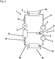
- FIG. 2 shows an alternative preferred embodiment, in which corresponding elements are provided with the same reference numerals.
- the refrigerant part is not fed to a mixing device upstream of the engine cooling, but rather directly to the second compression stage 4. Since the gaseous refrigerant part coming from the phase separation element 12 also The second compression stage 4 is supplied, the main refrigerant flow in the second compression stage 4 is brought to the high pressure level and heated. After heat has been given off and condensation in the condenser 9 and subsequent expansion via the throttle element 11, the main refrigerant flow, which has gaseous and liquid constituents, then cools the motor 5 and can absorb heat there.
- the liquid refrigerant part separated from the main flow of refrigerant by the phase separating element 12 is guided via the first line 16 and is first expanded to a low pressure level with the help of the throttle element 13. Evaporation then takes place in the evaporator 14, so that it is finally supplied in gaseous form to the first compression stage 3 of the compressor 3 and is brought to an intermediate pressure level there with simultaneous heating, in order then to reach the second compression stage 4.
- the motor which is required to drive the two-stage compressor, is cooled with the aid of the main refrigerant flow, that is to say through the entire refrigerant.
- An additional bypass connection to branch off some of the refrigerant to cool the engine is not required. Accordingly, there is a simplified structure, in particular by reducing the number of expansion valves required and thus simpler regulation.
- the engine's waste heat is returned to the refrigerant circuit without reducing the efficiency of the overall system due to the phase separation that occurs after the waste heat has been absorbed.
- the procedure according to the invention can be adapted to a refrigeration cycle with a single-stage compressor with relatively little effort, wherein an intermediate injection and an internal heat exchanger or also an intermediate injection and a phase separation can be used in a phase separation element.
- the refrigerant circuit can be reversed for defrosting and / or for cooling operation, but the phase separation element must always be flowed through in the same direction.
Landscapes
- Engineering & Computer Science (AREA)
- Physics & Mathematics (AREA)
- Mechanical Engineering (AREA)
- Thermal Sciences (AREA)
- General Engineering & Computer Science (AREA)
- Compressor (AREA)
- Motor Or Generator Cooling System (AREA)
- Applications Or Details Of Rotary Compressors (AREA)
Description
- Die Erfindung betrifft ein Verfahren zum Kühlen eines Motors nach dem Oberbegriff des Patentanspruchs 1 sowie eine Vorrichtung zum Durchführen des Verfahrens.
- Ein derartiger Kältemittelkreislauf mit einem zweistufigen Kompressor wird beispielsweise in Zusammenhang mit Wärmepumpen eingesetzt. Die beiden Kompressionsstufen des Kompressors werden dabei über einen Motor angetrieben, der dafür mechanisch mit diesem verbunden ist. Mit Hilfe der ersten Kompressionsstufe des Kompressors erfolgt eine Verdichtung des Kältemittelgases von einem niedrigen Niveau auf ein mittleres Niveau. In der zweiten Kompressionsstufe wird das Druckniveau dann weiter erhöht, bis das Kältemittel ein hohes Druckniveau aufweist. Über einen der zweiten Kompressionsstufe nachgeschalteten Kondensator kann dann eine Wärmeabgabe vom Kältemittel erfolgen, das anschließend entspannt wird und in einem Verdampfer erneut Wärme aufnehmen kann, um gasförmig der ersten Kompressionsstufe des Kompressors zugeführt zu werden.
- Je nach Betriebsweise lässt sich durch einen derartigen Kältemittelkreislauf dabei ein Erwärmen oder Abkühlen beispielsweise eines Raumes erreichen. Dabei dient das Kältemittel gleichzeitig zur Kühlung des Motors, der damit bei einer optimalen Betriebstemperatur betrieben werden kann.
- In Kältemittelkreisen wird üblicherweise der Motor des Kompressors entweder durch das vom Kompressor angesaugte oder durch das bereits verdichtete, gasförmige Kühlmittel gekühlt. Die Motorabwärme wird dabei dem gasförmigen Kältemittel entweder direkt vor oder direkt nach der Verdichtung zugeführt. Bei Kältemittelkreisen mit zweistufigen Kompressoren, die eine erste Kompressionsstufe und eine zweite Kompressionsstufe umfassen, ist es bekannt, den Motor mit dem auf einem mittleren Druckniveau befindlichen Kältemittel zu kühlen. Dies geschieht dann also entweder durch das Sauggas vor der zweiten bzw. zweiten Kompressionsstufe oder durch das Druckgas der ersten bzw. ersten Kompressionsstufe.
- In der Regel wird nur gasförmiges Kältemittel zum Kühlen des Motors genutzt, um eine Verdünnung des zur Schmierung für die Motorlager im Motor befindlichen Schmieröles zu verhindern. Dies könnte zu einer Mangelschmierung in den Lagern führen und damit eine Beschädigung des Motors verursachen. Allerdings vermindert die Kühlung mit Sauggas vor der Verdichtung in der zweiten Kompressionsstufe des Kompressors durch die Erwärmung des Sauggases die Effizienz des Kältemittelkreislaufes, weil sie eine Abnahme der Dichte des Sauggases und damit des geförderten Massenstroms bewirkt. Die Kühlung des Motors mit Druckgas nach der Verdichtung in der ersten Kompressionsstufe hat Verluste zur Folge und erhöht Temperatur des Druckgases der ersten Kompressionsstufe. Damit steigen auch die Anforderungen an die Temperaturbeständigkeit des Motors.
- Zur Kühlung eines Motors eines zweistufigen Kompressors ist es bekannt, aus dem Kältemittelkreislauf nach einem der zweiten Kompressionsstufe nachgeschalteten Kondensator einen Teilstrom vom Kältemittelhauptstrom abzuzweigen und über eine Art Bypass-Verbindung zu einer Motorkühlung zu leiten. Dabei erfolgt eine separate Entspannung in der Bypass-Leitung, für die je nach Betriebsmodus ein oder zwei Expansionsventile erforderlich sind, die eine gesonderte Regelung benötigen.
- Die bekannten Verfahren zur Kühlung des Motors haben also entweder eine Verringerung der Effizienz des Gesamtsystems zur Folge oder sind relativ aufwendig und nur mit zusätzlichen Leitungen und Expansionsventilen zu realisieren, für die noch eine gesonderte Regelung erforderlich ist.
- Der Erfindung liegt nun die Aufgabe zugrunde, die Nachteile des Standes der Technik zu beheben und insbesondere ein Verfahren und eine Vorrichtung zum Kühlen eines Motors anzugeben, bei dem die Abwärme des Motors in den Kältekreis zurückgeführt werden kann, ohne negativen Einfluss auf die Effizienz des Gesamtsystems zu haben. Dabei sollen der Herstellungsaufwand sowie der Regelungsaufwand möglichst gering sein und mit möglichst wenigen Bauelementen ausgekommen werden.
- Erfindungsgemäß wird diese Aufgabe durch ein Verfahren mit den Merkmalen des Patentanspruchs 1 und durch eine Vorrichtung mit den Merkmalen des Patentanspruchs 6 gelöst. Vorteilhafte Ausgestaltungen finden sich in den Unteransprüchen.
- Bei einem Verfahren zum Kühlen mindestens eines Motors, der mindestens einen zumindest zweistufigen Kompressor eines Kältemittelkreislaufs antreibt, der zumindest eine erste Kompressionsstufe und eine zweite Kompressionsstufe umfasst, wobei ein Kältemittel durch den Kältemittelkreislauf geleitet wird, das in der ersten Kompressionsstufe von einem niedrigen Druckniveau auf ein mittleres Druckniveau und in der zweiten Kompressionsstufe vom mittleren Druckniveau auf ein hohes Druckniveau gebracht und im Anschluss an die zweite Kompressionsstufe unter Wärmeabgabe auf das mittlere Druckniveau entspannt wird, ist erfindungsgemäß vorgesehen, dass der Motor mit einem zweiphasigen Kältemittel-Hauptstrom gekühlt wird, der das mittlere Druckniveau aufweist.
- Der zweiphasige Kältemittel-Hauptstrom enthält sowohl gasförmiges als auch flüssiges Kältemittel. Da der Kältemittel-Hauptstrom, also üblicherweise der gesamte Kältemittelstrom, für die Motorkühlung genutzt wird, sind keine zusätzlichen Expansionsventile nötig. Dementsprechend ist auch keine diesbezügliche Regelung erforderlich. Die vom Motor abgeführte Abwärme hat dabei keinen negativen Einfluss auf die Effizienz, da es weder auf der jeweiligen Druckseite, noch auf der jeweiligen Saugseite der Kompressionsstufen einen negativen Einfluss hat.
- Bei Kältemittelkompressoren mit mehr als zwei Kompressionsstufen findet das Verfahren zwischen zweien der Kompressionsstufen Anwendung. Bei mehr als einem Kältemittelkompressor kann das Verfahren zwischen zwei Kältemittelkompressoren angewendet werden. Dabei kann auch mehr als ein Motor gekühlt werden, wobei gegebenenfalls jedem Motor ein eigener Kältemittelkreislauf zugeordnet werden kann.
- In einer bevorzugten Weiterbildung wird der Kältemittel-Hauptstrom nach Kühlen des Motors in einen flüssigen Kältemittelteil und einen gasförmigen Kältemittelteil getrennt, wobei der gasförmige Kältemittelteil der zweiten Kompressionsstufe und der flüssige Kältemittelteil der ersten Kompressionsstufe des zweistufigen Kompressors zugeführt werden. Im Anschluss an die Kühlung des Motors folgt also eine Auftrennung des zweiphasigen Kältemittel-Hauptstroms in die beiden Phasen, wobei der gasförmige Anteil in der zweiten Kompressionsstufe weiter verdichtet wird. Damit kann in der zweiten Kompressionsstufe direkt eine sehr effiziente Verdichtung des gasförmigen Kältemittels auf einen hohen Druck bei hoher Temperatur erfolgen. Zum Trennen der Phasen des Kältemittels aus dem Kältemittel-Hauptstrom kann beispielsweise ein Mitteldruckbehälter, oder dienen, wobei es sich um einen Sammelbehälter handelt, in dem das Kältemittel in einen gasförmigen Anteil und in einen flüssigen Anteil getrennt wird.
- Bevorzugterweise wird dabei das Kältemittel vor der ersten Kompressionsstufe unter Wärmeaufnahme verdampft und nach der zweiten Kompressionsstufe unter Wärmeabgabe kondensiert. Dafür erfolgt beispielsweise nach dem Trennen des Kältemittel-Hauptstroms in den flüssigen und den gasförmigen Kältemittelteil eine Expansion des flüssigen Kältemittelteils mit einer anschließenden Verdampfung in einem Verdampfer, in dem Wärme beispielsweise aus der Umgebung aufgenommen werden kann. Dadurch geht der bis dahin flüssige Kältemittelteil ebenfalls in die gasförmige Phase über und wird gasförmig zur ersten Kompressionsstufe des zweistufigen Kompressors zugeführt, dort verdichtet und erwärmt. Im Anschluss an die zweite Kompressionsstufe kann beispielsweise ein Kondensator vorgesehen sein, in dem eine Kondensation des bis dahin gasförmigen Kältemittelteils erfolgt und dabei Wärme beispielsweise an die Umgebung abgegeben wird. Von dort wird das Kältemittel unter hohem Druck und teilweise verflüssigt weitergeführt und schließlich bis auf das mittlere Druckniveau entspannt.
- In einer bevorzugten Ausführungsform wird der Kältemittelteil nach der ersten Kompressionsstufe mit dem von der zweiten Kompressionsstufe nach Wärmeabgabe kommenden Kältemittelteil vor der Verwendung zum Kühlen des Motors zusammengeführt. Damit erfolgt eine Vereinigung der beiden Kältemittelteile, sodass der gesamte Kältemittelstrom zur Kühlung des Motors zur Verfügung steht.
- In einer alternativen Ausgestaltung ist vorgesehen, dass der Kältemittelteil nach der ersten Kompressionsstufe direkt der zweiten Kompressionsstufe zugeführt wird, wobei der nach Kühlen des Motors gasförmige Mittelteil der zweiten Kompressionsstufe zugeführt und mit dem von der ersten Kompressionsstufe kommenden Kältemittelteil zusammen geführt wird, wobei das den Kältemittel-Hauptstrom bildende, von der zweiten Kompressionsstufe nach Wärmeabgabe kommende Kältemittel zum Kühlen des Motors verwendet wird. Damit ergibt sich ein relativ einfacher Aufbau, wobei auch dann der gesamte Kältemittelstrom zur Kühlung des Motors genutzt wird.
- Bei einer Vorrichtung zum Durchführen des oben genannten Verfahrens, die insbesondere als zweistufige Wärmepumpe, Klimatisierungsgerät oder Kälteanlage ausgebildet ist, ist erfindungsgemäß vorgesehen, dass sie einen Motor und einen Kältemittelkreislauf aufweist, in dem ein zweistufiger Kompressor mit einer ersten Kompressionsstufe und einer zweiten Kompressionsstufe angeordnet ist, der vom Motor antreibbar ist, wobei eine Motorkühlung derart in den Kältemittelkreislauf eingebunden ist, dass sie von einem Kältemittel-Hauptstrom durchströmbar ist, wobei in Strömungsrichtung hinter der Motorkühlung ein Phasentrennelement angeordnet ist, das über eine Sauggasleitung für einen gasförmigen Kältemittelteil mit der zweiten Kompressionsstufe und über eine erste Leitung für einen flüssigen Kältemittelteil mit der ersten Kompressionsstufe des zweistufigen Kältemittelkompressors verbunden ist.
- Dadurch kann das gesamte, auf einem mittleren Druckniveau befindliche Kältemittel zur Motorkühlung genutzt werden und die Abwärme in den Kältemittelkreis zurückgeführt werden. Ein negativer Einfluss auf die Effizienz erfolgt damit nicht, da mit Hilfe des Phasentrennelementes im Anschluss an die Aufnahme der Abwärme des Motors beziehungsweise im Anschluss an die Motorkühlung eine Trennung in einen gasförmigen und einen flüssigen Kältemittelteil erfolgt, wobei nur der gasförmige Kältemittelteil der zweiten Kompressionsstufe zugeführt und damit weiter verdichtet wird. Diese kann daher mit hoher Effizienz betrieben werden.
- Auf zusätzliche Bypass-Verbindung mit zusätzlichen Expansionsventilen zur Versorgung der Motorkühlung kann somit verzichtet werden. Vielmehr wird die Motorkühlung einfach mit dem Kältemittel-Hauptstrom durchströmt, der entsprechende Wärme aufnehmen kann. Eine zusätzliche Regelung ist dafür nicht erforderlich. Damit wird der Herstellungs- und Regelungsaufwand gering gehalten.
- In einer bevorzugten Weiterbildung sind in der ersten Leitung vor der ersten Kompressionsstufe ein Verdampfer und gegebenenfalls ein Drosselelement sowie gegebenenfalls weitere Bauteile angeordnet. Damit kann eine Entspannung und Verdampfung des bis dahin flüssigen Kältemittelteils erfolgen, sodass dieses gasförmig der ersten Kompressionsstufe zuführbar ist. Im Verdampfer erfolgt dabei eine Wärmeaufnahme aus einer Umgebung, die dadurch gekühlt wird. Die weiteren Bauteile umfassen beispielsweise Filter oder ähnliches.
- Dabei ist besonders bevorzugt, dass in einer zweiten Leitung des Kältemittelkreislaufes nach der zweiten Kompressionsstufe ein Kondensator und gegebenenfalls ein Drosselelement sowie gegebenenfalls weitere Bauteile angeordnet sind. Im Kondensator kann von dem gasförmigen Kältemittelteil nach der zweiten Kompressionsstufe Wärme an die Umgebung abgegeben werden, wodurch dieser Kältemittelteil mindestens teilweise verflüssigt wird. Durch das anschließend angeordnete Drosselelement, das beispielsweise als einfache Drossel oder als Expansionsventil ausgebildet sein kann, erfolgt anschließend eine Entspannung dieses Kältemittelteils, sodass es auf einem mittleren Druckniveau flüssig und/oder gasförmig zur Motorkühlung genutzt werden kann. Die weiteren Bauteile können beispielsweise als Kühlelemente für eine Leistungselektronik oder ähnliches ausgebildet sein.
- In einer bevorzugten Ausgestaltung ist im Kältemittelkreislauf vor der Motorkühlung eine Mischeinrichtung angeordnet, die mit einer von der ersten Kompressionsstufe kommenden Druckgasleitung und der zweiten Leitung verbunden ist. In der Mischeinrichtung treffen also der von der ersten Kompressionsstufe kommende Kältemittelteil und der von der zweiten Kompressionsstufe kommende Kältemittelteil zusammen und können von dort gemeinsam zur Motorkühlung geführt werden. Damit dient der gesamte Kältemittelstrom zur Motorkühlung.
- In einer alternativen Ausgestaltung ist vorgesehen, dass die zweite Leitung mit der Motorkühlung verbunden ist, wobei eine von der ersten Kompressionsstufe kommende Druckgasleitung in die zur zweiten Kompressionsstufe führende Sauggasleitung mündet. Der gasförmige Kältemittelteil nach dem Phasentrennelement kann dabei mit dem von der ersten zur zweiten Kompressionsstufe laufenden Kältemittelteil vor der zweiten Kompressionsstufe zusammengeführt werden. Auch bei diesem vereinfachten Aufbau wird der gesamte Kältemittelstrom zur Motorkühlung geführt und dort zum Aufnehmen von Abwärme genutzt. Der von der ersten Kompressionsstufe kommende Kältemittelteil wird aber nicht direkt vor der Motorkühlung mit dem von der zweiten Kompressionsstufe kommenden Kältemittelteil kombiniert, sondern durchläuft erst ebenfalls die zweite Kompressionsstufe.
- In einer Kältemittelleitung zwischen Motorkühlung und Phasentrennelement können weitere Bauteile angeordnet sein. Dies sind beispielsweise Drosselelemente und/oder zusätzliche Kühlelemente, die beispielsweise zur Kühlung von Elementen einer Leistungselektronik dienen.
- Vorzugsweise weist der Kältemittelkompressor mehr als zwei Kompressionsstufen auf, wobei das Verfahren nach einem der Ansprüche 1 bis 5 zwischen zwei der Kompressionsstufen angewendet wird. Damit kann auch eine sehr starke Abkühlung erreicht werden.
- In einer bevorzugten Weiterbildung weist die Vorrichtung zwei Kältemittelkompressoren auf, wobei das Verfahren nach einem der Ansprüche 1 bis 5 zwischen den Kältemittelkompressoren oder zwischen Kompressionsstufen der Kältemittelkompressoren angewendet wird, wobei gegebenenfalls mehr als eine Motorkühlung erfolgt. Die Vorrichtung ist dadurch sehr universell einsetzbar.
- Die Erfindung wird im Folgenden anhand bevorzugter Ausführungsbeispiele in Verbindung mit den Zeichnungen näher beschrieben. Hierin zeigen:
-
Fig. 1 einen Kältemittelkreislauf mit einem zweistufigen Kompressor einer ersten Ausführungsform und -
Fig. 2 einen Kältemittelkreislauf mit einem zweistufigen Kompressor einer zweiten Ausführungsform. - In
Fig. 1 ist schematisch ein Kältemittelkreislauf 1 einer Wärmepumpe dargestellt, der einen zweistufigen Kompressor 2 mit einer ersten Kompressionsstufe 3 und einer zweiten Kompressionsstufe 4 aufweist. Der zweistufige Kompressor 2 wird mit einem Motor 5 betrieben, wobei eine mechanische Verbindung zwischen dem Motor 5 und den Kompressionsstufen 3, 4 des zweistufigen Kompressors 2 aus Gründen der Übersichtlichkeit nicht dargestellt ist. - Mit Hilfe der Kompressionsstufen 3, 4 des zweistufigen Kompressors 2 erfolgt ein Anheben des Druckniveaus eines Kältemittels von einem ersten Druckniveau zunächst auf ein mittleres Druckniveau und anschließend auf ein hohes Druckniveau. Als Kältemittel wird dabei ein unter Überdruck flüssiges Fluid, das nach einer Druckentlastung und Wärmeaufnahme gasförmig wird, verwendet. Das Kältemittel wird beispielsweise gasförmig und mit niedrigem Druck der ersten Kompressionsstufe 3 des Kompressors 2 zugeführt und dort auf ein mittleres Druckniveau gebracht, wobei es gleichzeitig erwärmt wird.
- Über eine Druckgasleitung 6 gelangt ein gasförmiger Kältemittelanteil dann bei dem Kältemittelkreislauf gemäß
Figur 1 zu einer Mischeinrichtung 7 und wird dort mit einem von der zweiten Kompressionsstufe 4 kommenden Kältemittelteil zusammengeführt. Dieser Kältemittelteil war der zweiten Kompressionsstufe des Kompressors 2 gasförmig und mit einem mittleren Druckniveau zugeführt worden und wurde in der zweiten Kompressionsstufe 4 bei gleichzeitiger Erwärmung auf ein hohes Druckniveau gebracht. Der gasförmige Kältemittelteil wird dann im Anschluss an die zweite Kompressionsstufe 4 über eine zweite Leitung 8 einem Kondensator 9 zugeführt. Dort erfolgt eine Wärmeabgabe vom Kältemittelteil an eine Umgebung beziehungsweise Wärmesenke 10. Der dadurch kondensierte Wärmemittelteil, der sowohl flüssige als auch gasförmige Phasen aufweisen kann, wird anschließend mit Hilfe eines Drosselelementes 11, das beispielsweise als Expansionsventil ausgebildet ist, auf das mittlere Druckniveau entspannt, mit der dieser Kältemittelteil bei der Mischeinrichtung 7 ankommt und mit dem von der ersten Kompressionsstufe 3 kommenden Kältemittelteil zusammengeführt wird. - Die zusammengeführten Kältemittelteile, also der Kältemittel-Hauptstrom, der den gesamten Volumenstrom umfasst, gelangt von der Mischeinrichtung 7 zu einer Motorkühlung des Motors 5 und nimmt dort Wärme vom Motor 5 auf. Anschließend wird der Kältemittel-Hauptstrom in einem Phasentrennelement 12 in den gasförmigen Kältemittelteil und den flüssigen Kältemittelteil aufgetrennt. Der gasförmige Kältemittelteil wird dann wiederum der zweiten Kompressionsstufe 4 zugeführt.
- Der flüssige Kältemittelteil wird mit Hilfe eines Drosselelementes 13, das wiederum als Expansionsventil ausgebildet sein kann, entspannt und mit niedrigem Druck und niedriger Temperatur einem Verdampfer 14 zugeführt, in dem der flüssige Kältemittelteil in eine gasförmige Phase überführt wird. Der Verdampfer 14 nimmt dabei aus der Umgebung beziehungsweise von einer Wärmequelle 15 Wärme auf, die vom Kältemittelteil aufgenommen wird. Dabei sind das Drosselelement 13 und der Verdampfer 14 in einer ersten Leitung 16 angeordnet, die das Phasentrennelement 12 mit der ersten Kompressionsstufe 3 des zweistufigen Kompressors 2 verbindet. In der ersten Kompressionsstufe 3 erfolgt dann eine Erhöhung des Druckes des im Verdampfer 14 verdampften Kältemittelteils, sodass dieser auf mittlerem Druckniveau und mit erhöhter Temperatur wiederum der Mischeinrichtung 7 zugeführt werden kann.
-
Figur 2 zeigt ein alternatives bevorzugtes Ausführungsbeispiel, bei dem entsprechende Elemente mit den gleichen Bezugszeichen versehen sind. Im Unterschied zum Ausführungsbeispiel nachFigur 1 wird der Kältemittelteil nach der ersten Kompressionsstufe 3 nicht einer der Motorkühlung vorgelagerten Mischeinrichtung zugeführt, sondern direkt der zweiten Kompressionsstufe 4. Da auch der vom Phasentrennelement 12 kommende gasförmige Kältemittelteil der zweiten Kompressionsstufe 4 zugeführt wird, wird der Kältemittel-Hauptstrom in der zweiten Kompressionsstufe 4 auf das hohe Druckniveau gebracht und dabei erwärmt. Nach Wärmeabgabe und Kondensation im Kondensator 9 und anschließender Entspannung über das Drosselelement 11 gelangt dann der Kältemittel-Hauptstrom, der gasförmige und flüssige Bestandteile aufweist, zur Kühlung des Motors 5 und kann dort Wärme aufnehmen. Der vom Phasentrennelement 12 aus dem Kältemittel-Hauptstrom abgetrennte flüssige Kältemittelteil wird über die erste Leitung 16 geführt und zunächst mit Hilfe des Drosselelementes 13 auf ein niedriges Druckniveau entspannt. Anschließend erfolgt eine Verdampfung im Verdampfer 14, so dass es schließlich gasförmig der ersten Kompressionsstufe 3 des Kompressors 3 zugeführt und dort bei gleichzeitiger Erwärmung auf ein mittleres Druckniveau gebracht wird, um dann zur zweiten Kompressionsstufe 4 zu gelangen. - Bei den erfindungsgemäßen Verfahren beziehungsweise bei den erfindungsgemäßen Vorrichtungen, bei der es sich insbesondere um eine Wärmepumpenanordnung handelt, erfolgt eine Kühlung des Motors, der zum Antreiben des zweistufigen Kompressors erforderlich ist, mit Hilfe des Kältemittel-Hauptstroms, also durch das gesamte Kältemittel. Eine zusätzliche Bypass-Verbindung, um einen Teil des Kältemittels zur Kühlung des Motors abzuzweigen, ist nicht erforderlich. Dementsprechend ergibt sich ein vereinfachter Aufbau insbesondere durch Reduzieren der Anzahl der erforderlichen Expansionsventile und damit eine einfachere Regelung.
- Die Abwärme des Motors wird dabei dem Kältemittelkreislauf wieder zugeführt, ohne aufgrund der nach Aufnahme der Abwärme erfolgenden Phasentrennung die Effizienz des Gesamtsystems zu verschlechtern.
- Mit relativ geringem Aufwand lässt sich das erfindungsgemäße Vorgehen an einen Kältekreislauf mit einem einstufigen Kompressor anpassen, wobei eine Zwischeneinspritzung und ein interner Wärmeübertrager oder auch eine Zwischeneinspritzung und eine Phasentrennung in einem Phasentrennelement Anwendung finden können.
- Aufgrund des Designs des Kältemittelkreislaufs kann eine Umkehrung des Kältekreises zur Abtauung und/oder für den Kühlbetrieb erfolgen, wobei das Phasentrennelement jedoch immer in gleicher Richtung durchströmt werden muss.
Claims (11)
- Verfahren zum Kühlen eines Motors, der mindestens einen zumindest zweistufigen Kompressor (2) eines Kältemittelkreislaufes (1) antreibt, der zumindest eine erste Kompressionsstufe (3) und eine zweite Kompressionsstufe (4) umfasst, wobei ein Kältemittel durch den Kältemittelkreislauf (1) geleitet wird, das in der ersten Kompressionsstufe (3) von einem niedrigen Druckniveau auf ein mittleres Druckniveau und in der zweiten Kompressionsstufe (4) vom mittleren Druckniveau auf ein hohes Druckniveau gebracht wird und im Anschluss an die zweite Kompressionsstufe (4) unter Wärmeabgabe auf das mittlere Druckniveau entspannt wird,
dadurch gekennzeichnet, dass
der Motor (5) mit dem gesamten Kältemittelstrom der im Kältemittelkreislauf zirkuliert, als zweiphasiger Kältemittel-Hauptstrom gekühlt wird, der das mittlere Druckniveau aufweist. - Verfahren nach Anspruch 1, dadurch gekennzeichnet, dass der Kältemittel-Hauptstrom nach Kühlen des Motors (5) in einen flüssigen Kältemittelteil und einen gasförmigen Kältemittelteil getrennt wird, wobei der gasförmige Kältemittelteil der zweiten Kompressionsstufe (4) und der flüssige Kältemittelteil der ersten Kompressionsstufe (3) des zweistufigen Kompressors (2) zugeführt wird.
- Verfahren nach Anspruch 1 oder 2, dadurch gekennzeichnet, dass das Kältemittel vor der ersten Kompressionsstufe (3) unter Wärmeaufnahme verdampft und nach der zweiten Kompressionsstufe (4) unter Wärmeabgabe kondensiert wird.
- Verfahren nach einem der Ansprüche 1 bis 3, dadurch gekennzeichnet, dass der Kältemittelteil nach der ersten Kompressionsstufe (3) mit dem von der zweiten Kompressionsstufe (4) nach Wärmeabgabe kommenden Kältemittelteil vor der Verwendung zum Kühlen des Motors (5) zusammengeführt wird.
- Verfahren nach einem der Ansprüche 1 bis 3, dadurch gekennzeichnet, dass der Kältemittelteil nach der ersten Kompressionsstufe (3) direkt der zweiten Kompressionsstufe (4) zugeführt wird, wobei der nach Kühlen des Motors (5) gasförmige Kältemittelteil der zweiten Kompressionsstufe (4) zugeführt und mit dem von der ersten Kompressionsstufe (3) kommenden Kältemittelteil zusammengeführt wird und das den Kältemittel-Hauptstrom bildende, von der zweiten Kompressionsstufe (4) kommende Kältemittel nach Wärmeabgabe zum Kühlen des Motors (5) verwendet wird.
- Vorrichtung, insbesondere zweistufige Wärmepumpe, Klimatisierungsgerät oder Kälteanlage, zum Durchführen eines Verfahrens nach den Ansprüchen 1 bis 5, umfassend einen Motor (5) und einen Kältemittelkreislauf (1) ; in dem ein zweistufiger Kompressor (2) mit einer ersten Kompressionsstufe (3) und einer zweiten Kompressionsstufe (4) angeordnet ist, der vom Motor (5) antreibbar ist, dadurch gekennzeichnet, dass eine Motorkühlung derart in den Kältemittelkreislauf (1) eingebunden ist, dass sie von dem gesamten Kältemittelstrom, der im Kältemittelkreislauf zirkuliert, als zweiphasiger Kältemittel-Hauptstrom durchströmbar ist, wobei in Strömungsrichtung hinter der Motorkühlung ein Phasentrennelement (12) angeordnet ist, das über eine Sauggasleitung (17) für einen gasförmigen Kältemittelteil mit der zweiten Kompressionsstufe (4) und über eine erste Leitung (16) für einen flüssigen Kältemittelteil mit der ersten Kompressionsstufe (3) des zweistufigen Kältemittelkompressors (2) verbunden ist.
- Vorrichtung nach Anspruch 6, dadurch gekennzeichnet, dass in der ersten Leitung (16) vor der ersten Kompressionsstufe (3) ein Verdampfer (14) und gegebenenfalls ein Drosselelement (13) sowie gegebenenfalls weitere Bauteile angeordnet sind.
- Vorrichtung nach Anspruch 6 oder 7, dadurch gekennzeichnet, dass in einer zweiten Leitung (8) des Kältemittelkreislaufs (1) nach der zweiten Kompressionsstufe (4) ein Kondensator (9) und gegebenenfalls ein Drosselelement (11) sowie gegebenenfalls weitere Bauteile angeordnet sind.
- Vorrichtung nach einem der Ansprüche 6 bis 8, dadurch gekennzeichnet, dass im Kältemittelkreislauf (1) vor der Motorkühlung eine Mischeinrichtung angeordnet ist, die mit einer von der ersten Kompressionsstufe (3) kommenden Druckgasleitung (6) und der zweiten Leitung (8) verbunden ist.
- Vorrichtung nach einem der Ansprüche 6 bis 8, dadurch gekennzeichnet, dass die zweite Leitung (8) mit der Motorkühlung verbunden ist, wobei eine von der ersten Kompressionsstufe (3) kommende Druckgasleitung (6) in die zur zweiten Kompressionsstufe (4) führende Sauggasleitung (17) mündet.
- Vorrichtung nach einem der Ansprüche 6 bis 8, dadurch gekennzeichnet, dass in einer Kältemittelleitung zwischen Motorkühlung (5) und Phasentrennelement (12) weitere Bauteile angeordnet sind.
Applications Claiming Priority (2)
| Application Number | Priority Date | Filing Date | Title |
|---|---|---|---|
| DE102013207344.5A DE102013207344A1 (de) | 2013-04-23 | 2013-04-23 | Verfahren und Vorrichtung zum Kühlen eines Motors |
| PCT/EP2014/056567 WO2014173641A1 (de) | 2013-04-23 | 2014-04-02 | Verfahren und vorrichtung zum kühlen eines motors |
Publications (2)
| Publication Number | Publication Date |
|---|---|
| EP2989397A1 EP2989397A1 (de) | 2016-03-02 |
| EP2989397B1 true EP2989397B1 (de) | 2020-06-10 |
Family
ID=50434195
Family Applications (1)
| Application Number | Title | Priority Date | Filing Date |
|---|---|---|---|
| EP14714996.7A Active EP2989397B1 (de) | 2013-04-23 | 2014-04-02 | Verfahren und vorrichtung zum kühlen eines motors |
Country Status (5)
| Country | Link |
|---|---|
| US (1) | US20160273812A1 (de) |
| EP (1) | EP2989397B1 (de) |
| CN (1) | CN105143790B (de) |
| DE (1) | DE102013207344A1 (de) |
| WO (1) | WO2014173641A1 (de) |
Families Citing this family (2)
| Publication number | Priority date | Publication date | Assignee | Title |
|---|---|---|---|---|
| US10391835B2 (en) * | 2015-05-15 | 2019-08-27 | Ford Global Technologies, Llc | System and method for de-icing a heat pump |
| WO2019068322A1 (de) * | 2017-10-04 | 2019-04-11 | Bitzer Kühlmaschinenbau Gmbh | Kältemittelverdichteranlage |
Family Cites Families (9)
| Publication number | Priority date | Publication date | Assignee | Title |
|---|---|---|---|---|
| US2746269A (en) * | 1955-03-17 | 1956-05-22 | Trane Co | Plural stage refrigerating apparatus |
| US3232074A (en) * | 1963-11-04 | 1966-02-01 | American Radiator & Standard | Cooling means for dynamoelectric machines |
| FR2620205A1 (fr) * | 1987-09-04 | 1989-03-10 | Zimmern Bernard | Compresseur hermetique pour refrigeration avec moteur refroidi par gaz d'economiseur |
| JP3247992B2 (ja) * | 1996-04-18 | 2002-01-21 | 株式會社三進 | 5又は8kW冷凍装置及び該装置のための遠心圧縮機のアッセンブリ |
| WO1997039292A1 (en) * | 1996-04-18 | 1997-10-23 | Zakrytoe Aktsionernoe Obschestvo Nauchno-Proizvodstvennoe Obiedinenie 'vik' | 5 OR 8 kW REFRIGERATING SYSTEM AND CENTRIFUGAL COMPRESSOR ASSEMBLY FOR SAID SYSTEM |
| KR100430091B1 (ko) * | 1997-07-10 | 2004-07-15 | 엘지.필립스 엘시디 주식회사 | 액정표시장치 |
| KR100288315B1 (ko) * | 1999-03-15 | 2001-04-16 | 김평길 | 2단 원심압축기 |
| US7600390B2 (en) * | 2004-10-21 | 2009-10-13 | Tecumseh Products Company | Method and apparatus for control of carbon dioxide gas cooler pressure by use of a two-stage compressor |
| CN201488382U (zh) * | 2009-09-11 | 2010-05-26 | 河南千年冷冻设备有限公司 | 一种双级制冷系统 |
-
2013
- 2013-04-23 DE DE102013207344.5A patent/DE102013207344A1/de not_active Withdrawn
-
2014
- 2014-04-02 WO PCT/EP2014/056567 patent/WO2014173641A1/de not_active Ceased
- 2014-04-02 EP EP14714996.7A patent/EP2989397B1/de active Active
- 2014-04-02 US US14/785,910 patent/US20160273812A1/en not_active Abandoned
- 2014-04-02 CN CN201480022397.2A patent/CN105143790B/zh not_active Expired - Fee Related
Non-Patent Citations (1)
| Title |
|---|
| None * |
Also Published As
| Publication number | Publication date |
|---|---|
| US20160273812A1 (en) | 2016-09-22 |
| DE102013207344A1 (de) | 2014-10-23 |
| EP2989397A1 (de) | 2016-03-02 |
| CN105143790A (zh) | 2015-12-09 |
| WO2014173641A1 (de) | 2014-10-30 |
| CN105143790B (zh) | 2018-02-23 |
Similar Documents
| Publication | Publication Date | Title |
|---|---|---|
| EP3697635B1 (de) | Verfahren zum betreiben eines kältemittelkreislaufs sowie fahrzeugkälteanlage | |
| DE602004003710T2 (de) | Klimaregelungssystem mit einem dampfkompressionskreislauf in kombination mit einem absorptionskreislauf | |
| DE102015122721B4 (de) | Klimatisierungssystem eines Kraftfahrzeugs und Verfahren zum Betreiben des Klimatisierungssystems | |
| EP3444542B1 (de) | Kreislaufsystem für ein fahrzeug und verfahren dazu | |
| DE102010051976B4 (de) | Klimaanlage für ein Kraftfahrzeug | |
| EP2199706B1 (de) | Schaltschrank-Klimagerät und Verfahren zum Betreiben eines Solchen | |
| WO2019007558A1 (de) | Kälteanlage für ein fahrzeug mit einem einen wärmeübertrager aufweisenden kältemittelkreislauf sowie wärmeübertrager für eine solche kälteanlage | |
| DE112015002568T5 (de) | Ejektor-Kühlkreislauf | |
| EP2928710A1 (de) | Verfahren zum betreiben eines kältemittelkreislaufs als wärmepumpe sowie als wärmepumpe betreibbarer kältemittelkreislauf | |
| DE102016004999B3 (de) | Fahrzeugklimaanlage | |
| WO2022106119A1 (de) | Kühleinrichtung für ein fahrzeug | |
| EP1719650A1 (de) | Vorrichtung zur Luftkonditionierung für ein Kraftfahrzeug | |
| DE10313850B4 (de) | Kältemittelkreislauf mit zweistufiger Verdichtung für einen kombinierten Kälteanlagen- und Wärmepumpenbetrieb, insbesondere für Kraftfahrzeuge | |
| DE112015000750T5 (de) | Kältefluidkreislauf zur thermischen Behandlung eines Kraftfahrzeugs | |
| EP2989397B1 (de) | Verfahren und vorrichtung zum kühlen eines motors | |
| DE102008005076A1 (de) | Kältemittelkreis und Verfahren zum Betreiben eines Kältemittelkreises | |
| DE19708428C2 (de) | Kälteanlage | |
| DE3313429A1 (de) | Waermepumpenvorrichtung | |
| DE102017213973A1 (de) | Verfahren zum Betreiben einer Kälteanlage eines Fahrzeugs mit einem eine Kühl- und Heizfunktion aufweisenden Kältemittelkreislauf | |
| DE112017005948T5 (de) | Klimatisierungsvorrichtung | |
| DE102020120399A1 (de) | Kraftfahrzeug-Temperierungssystem mit zwei an einen jeweiligen Kältemittelkreislauf angeschlossenen Verdampfern im selben Kältemittelkreislauf; Kraftfahrzeug sowie Verfahren | |
| EP1010954A1 (de) | Verfahren und Vorrichtung zum Abkühlen eines Gasstromes | |
| DE102008011255A1 (de) | Ejektorzyklus mit einphasigem Strahl | |
| WO2014131606A1 (de) | Kältemaschine und verfahren zum betreiben einer kältemaschine | |
| DE102020216027A1 (de) | Gaswärmepumpensystem und Verfahren zu seiner Steuerung |
Legal Events
| Date | Code | Title | Description |
|---|---|---|---|
| PUAI | Public reference made under article 153(3) epc to a published international application that has entered the european phase |
Free format text: ORIGINAL CODE: 0009012 |
|
| 17P | Request for examination filed |
Effective date: 20151123 |
|
| AK | Designated contracting states |
Kind code of ref document: A1 Designated state(s): AL AT BE BG CH CY CZ DE DK EE ES FI FR GB GR HR HU IE IS IT LI LT LU LV MC MK MT NL NO PL PT RO RS SE SI SK SM TR |
|
| AX | Request for extension of the european patent |
Extension state: BA ME |
|
| DAX | Request for extension of the european patent (deleted) | ||
| GRAP | Despatch of communication of intention to grant a patent |
Free format text: ORIGINAL CODE: EPIDOSNIGR1 |
|
| STAA | Information on the status of an ep patent application or granted ep patent |
Free format text: STATUS: GRANT OF PATENT IS INTENDED |
|
| INTG | Intention to grant announced |
Effective date: 20190322 |
|
| GRAS | Grant fee paid |
Free format text: ORIGINAL CODE: EPIDOSNIGR3 |
|
| GRAA | (expected) grant |
Free format text: ORIGINAL CODE: 0009210 |
|
| STAA | Information on the status of an ep patent application or granted ep patent |
Free format text: STATUS: THE PATENT HAS BEEN GRANTED |
|
| AK | Designated contracting states |
Kind code of ref document: B1 Designated state(s): AL AT BE BG CH CY CZ DE DK EE ES FI FR GB GR HR HU IE IS IT LI LT LU LV MC MK MT NL NO PL PT RO RS SE SI SK SM TR |
|
| APBM | Appeal reference recorded |
Free format text: ORIGINAL CODE: EPIDOSNREFNO |
|
| REG | Reference to a national code |
Ref country code: GB Ref legal event code: FG4D Free format text: NOT ENGLISH |
|
| PUAC | Information related to the publication of a b1 document modified or deleted |
Free format text: ORIGINAL CODE: 0009299EPPU |
|
| STAA | Information on the status of an ep patent application or granted ep patent |
Free format text: STATUS: GRANT OF PATENT IS INTENDED |
|
| REG | Reference to a national code |
Ref country code: CH Ref legal event code: EP Ref country code: CH Ref legal event code: PK Free format text: DIE ERTEILUNG WURDE VOM EPA WIDERRUFEN. |
|
| REG | Reference to a national code |
Ref country code: AT Ref legal event code: REF Ref document number: 1175930 Country of ref document: AT Kind code of ref document: T Effective date: 20190915 |
|
| APBV | Interlocutory revision of appeal recorded |
Free format text: ORIGINAL CODE: EPIDOSNIRAPE |
|
| REG | Reference to a national code |
Ref country code: DE Ref legal event code: R096 Ref document number: 502014012564 Country of ref document: DE |
|
| REG | Reference to a national code |
Ref country code: IE Ref legal event code: FG4D Free format text: LANGUAGE OF EP DOCUMENT: GERMAN |
|
| DB1 | Publication of patent cancelled |
Effective date: 20190906 |
|
| REG | Reference to a national code |
Ref country code: LU Ref legal event code: HK Effective date: 20191002 |
|
| GRAJ | Information related to disapproval of communication of intention to grant by the applicant or resumption of examination proceedings by the epo deleted |
Free format text: ORIGINAL CODE: EPIDOSDIGR1 |
|
| GRAP | Despatch of communication of intention to grant a patent |
Free format text: ORIGINAL CODE: EPIDOSNIGR1 |
|
| REG | Reference to a national code |
Ref country code: AT Ref legal event code: REZ Ref document number: 1175930 Country of ref document: AT Kind code of ref document: T Effective date: 20190904 |
|
| INTG | Intention to grant announced |
Effective date: 20191125 |
|
| REG | Reference to a national code |
Ref country code: DE Ref legal event code: R107 Ref document number: 502014012564 Country of ref document: DE |
|
| GRAS | Grant fee paid |
Free format text: ORIGINAL CODE: EPIDOSNIGR3 |
|
| RAP1 | Party data changed (applicant data changed or rights of an application transferred) |
Owner name: ROBERT BOSCH GMBH |
|
| GRAA | (expected) grant |
Free format text: ORIGINAL CODE: 0009210 |
|
| STAA | Information on the status of an ep patent application or granted ep patent |
Free format text: STATUS: THE PATENT HAS BEEN GRANTED |
|
| AK | Designated contracting states |
Kind code of ref document: B1 Designated state(s): AL AT BE BG CH CY CZ DE DK EE ES FI FR GB GR HR HU IE IS IT LI LT LU LV MC MK MT NL NO PL PT RO RS SE SI SK SM TR |
|
| REG | Reference to a national code |
Ref country code: GB Ref legal event code: FG4D Free format text: NOT ENGLISH |
|
| REG | Reference to a national code |
Ref country code: CH Ref legal event code: EP Ref country code: CH Ref legal event code: PK Free format text: DIE ERTEILUNG VOM 04.09.2019 WURDE VOM EPA WIDERRUFEN. Ref country code: AT Ref legal event code: REF Ref document number: 1175930 Country of ref document: AT Kind code of ref document: T Effective date: 20200615 |
|
| REG | Reference to a national code |
Ref country code: DE Ref legal event code: R096 Ref document number: 502014012564 Country of ref document: DE |
|
| REG | Reference to a national code |
Ref country code: SE Ref legal event code: TRGR |
|
| REG | Reference to a national code |
Ref country code: LT Ref legal event code: MG4D |
|
| PG25 | Lapsed in a contracting state [announced via postgrant information from national office to epo] |
Ref country code: LT Free format text: LAPSE BECAUSE OF FAILURE TO SUBMIT A TRANSLATION OF THE DESCRIPTION OR TO PAY THE FEE WITHIN THE PRESCRIBED TIME-LIMIT Effective date: 20200610 Ref country code: FI Free format text: LAPSE BECAUSE OF FAILURE TO SUBMIT A TRANSLATION OF THE DESCRIPTION OR TO PAY THE FEE WITHIN THE PRESCRIBED TIME-LIMIT Effective date: 20200610 Ref country code: NO Free format text: LAPSE BECAUSE OF FAILURE TO SUBMIT A TRANSLATION OF THE DESCRIPTION OR TO PAY THE FEE WITHIN THE PRESCRIBED TIME-LIMIT Effective date: 20200910 |
|
| REG | Reference to a national code |
Ref country code: NL Ref legal event code: MP Effective date: 20200610 |
|
| PG25 | Lapsed in a contracting state [announced via postgrant information from national office to epo] |
Ref country code: HR Free format text: LAPSE BECAUSE OF FAILURE TO SUBMIT A TRANSLATION OF THE DESCRIPTION OR TO PAY THE FEE WITHIN THE PRESCRIBED TIME-LIMIT Effective date: 20200610 Ref country code: BG Free format text: LAPSE BECAUSE OF FAILURE TO SUBMIT A TRANSLATION OF THE DESCRIPTION OR TO PAY THE FEE WITHIN THE PRESCRIBED TIME-LIMIT Effective date: 20200910 Ref country code: LV Free format text: LAPSE BECAUSE OF FAILURE TO SUBMIT A TRANSLATION OF THE DESCRIPTION OR TO PAY THE FEE WITHIN THE PRESCRIBED TIME-LIMIT Effective date: 20200610 |
|
| REG | Reference to a national code |
Ref country code: CH Ref legal event code: PL |
|
| PG25 | Lapsed in a contracting state [announced via postgrant information from national office to epo] |
Ref country code: NL Free format text: LAPSE BECAUSE OF FAILURE TO SUBMIT A TRANSLATION OF THE DESCRIPTION OR TO PAY THE FEE WITHIN THE PRESCRIBED TIME-LIMIT Effective date: 20200610 |
|
| PG25 | Lapsed in a contracting state [announced via postgrant information from national office to epo] |
Ref country code: PT Free format text: LAPSE BECAUSE OF FAILURE TO SUBMIT A TRANSLATION OF THE DESCRIPTION OR TO PAY THE FEE WITHIN THE PRESCRIBED TIME-LIMIT Effective date: 20201012 Ref country code: EE Free format text: LAPSE BECAUSE OF FAILURE TO SUBMIT A TRANSLATION OF THE DESCRIPTION OR TO PAY THE FEE WITHIN THE PRESCRIBED TIME-LIMIT Effective date: 20200610 Ref country code: SM Free format text: LAPSE BECAUSE OF FAILURE TO SUBMIT A TRANSLATION OF THE DESCRIPTION OR TO PAY THE FEE WITHIN THE PRESCRIBED TIME-LIMIT Effective date: 20200610 Ref country code: RO Free format text: LAPSE BECAUSE OF FAILURE TO SUBMIT A TRANSLATION OF THE DESCRIPTION OR TO PAY THE FEE WITHIN THE PRESCRIBED TIME-LIMIT Effective date: 20200610 Ref country code: ES Free format text: LAPSE BECAUSE OF FAILURE TO SUBMIT A TRANSLATION OF THE DESCRIPTION OR TO PAY THE FEE WITHIN THE PRESCRIBED TIME-LIMIT Effective date: 20200610 Ref country code: CZ Free format text: LAPSE BECAUSE OF FAILURE TO SUBMIT A TRANSLATION OF THE DESCRIPTION OR TO PAY THE FEE WITHIN THE PRESCRIBED TIME-LIMIT Effective date: 20200610 |
|
| PG25 | Lapsed in a contracting state [announced via postgrant information from national office to epo] |
Ref country code: SK Free format text: LAPSE BECAUSE OF FAILURE TO SUBMIT A TRANSLATION OF THE DESCRIPTION OR TO PAY THE FEE WITHIN THE PRESCRIBED TIME-LIMIT Effective date: 20200610 Ref country code: PL Free format text: LAPSE BECAUSE OF FAILURE TO SUBMIT A TRANSLATION OF THE DESCRIPTION OR TO PAY THE FEE WITHIN THE PRESCRIBED TIME-LIMIT Effective date: 20200610 |
|
| REG | Reference to a national code |
Ref country code: DE Ref legal event code: R097 Ref document number: 502014012564 Country of ref document: DE |
|
| PG25 | Lapsed in a contracting state [announced via postgrant information from national office to epo] |
Ref country code: MC Free format text: LAPSE BECAUSE OF FAILURE TO SUBMIT A TRANSLATION OF THE DESCRIPTION OR TO PAY THE FEE WITHIN THE PRESCRIBED TIME-LIMIT Effective date: 20200610 |
|
| PLBE | No opposition filed within time limit |
Free format text: ORIGINAL CODE: 0009261 |
|
| STAA | Information on the status of an ep patent application or granted ep patent |
Free format text: STATUS: NO OPPOSITION FILED WITHIN TIME LIMIT |
|
| PG25 | Lapsed in a contracting state [announced via postgrant information from national office to epo] |
Ref country code: DK Free format text: LAPSE BECAUSE OF FAILURE TO SUBMIT A TRANSLATION OF THE DESCRIPTION OR TO PAY THE FEE WITHIN THE PRESCRIBED TIME-LIMIT Effective date: 20200610 |
|
| 26N | No opposition filed |
Effective date: 20210311 |
|
| PG25 | Lapsed in a contracting state [announced via postgrant information from national office to epo] |
Ref country code: SI Free format text: LAPSE BECAUSE OF FAILURE TO SUBMIT A TRANSLATION OF THE DESCRIPTION OR TO PAY THE FEE WITHIN THE PRESCRIBED TIME-LIMIT Effective date: 20200610 |
|
| PGFP | Annual fee paid to national office [announced via postgrant information from national office to epo] |
Ref country code: FR Payment date: 20210421 Year of fee payment: 8 Ref country code: DE Payment date: 20210624 Year of fee payment: 8 Ref country code: IT Payment date: 20210430 Year of fee payment: 8 |
|
| PGFP | Annual fee paid to national office [announced via postgrant information from national office to epo] |
Ref country code: SE Payment date: 20210420 Year of fee payment: 8 |
|
| GBPC | Gb: european patent ceased through non-payment of renewal fee |
Effective date: 20210402 |
|
| PG25 | Lapsed in a contracting state [announced via postgrant information from national office to epo] |
Ref country code: LU Free format text: LAPSE BECAUSE OF NON-PAYMENT OF DUE FEES Effective date: 20210402 |
|
| REG | Reference to a national code |
Ref country code: BE Ref legal event code: MM Effective date: 20210430 |
|
| PG25 | Lapsed in a contracting state [announced via postgrant information from national office to epo] |
Ref country code: GB Free format text: LAPSE BECAUSE OF NON-PAYMENT OF DUE FEES Effective date: 20210402 |
|
| PG25 | Lapsed in a contracting state [announced via postgrant information from national office to epo] |
Ref country code: IE Free format text: LAPSE BECAUSE OF NON-PAYMENT OF DUE FEES Effective date: 20210402 |
|
| REG | Reference to a national code |
Ref country code: AT Ref legal event code: MM01 Ref document number: 1175930 Country of ref document: AT Kind code of ref document: T Effective date: 20210402 |
|
| PG25 | Lapsed in a contracting state [announced via postgrant information from national office to epo] |
Ref country code: BE Free format text: LAPSE BECAUSE OF NON-PAYMENT OF DUE FEES Effective date: 20210430 |
|
| PG25 | Lapsed in a contracting state [announced via postgrant information from national office to epo] |
Ref country code: AT Free format text: LAPSE BECAUSE OF NON-PAYMENT OF DUE FEES Effective date: 20210402 |
|
| REG | Reference to a national code |
Ref country code: DE Ref legal event code: R119 Ref document number: 502014012564 Country of ref document: DE |
|
| REG | Reference to a national code |
Ref country code: SE Ref legal event code: EUG |
|
| PG25 | Lapsed in a contracting state [announced via postgrant information from national office to epo] |
Ref country code: SE Free format text: LAPSE BECAUSE OF NON-PAYMENT OF DUE FEES Effective date: 20220403 Ref country code: FR Free format text: LAPSE BECAUSE OF NON-PAYMENT OF DUE FEES Effective date: 20220430 Ref country code: DE Free format text: LAPSE BECAUSE OF NON-PAYMENT OF DUE FEES Effective date: 20221103 |
|
| PG25 | Lapsed in a contracting state [announced via postgrant information from national office to epo] |
Ref country code: RS Free format text: LAPSE BECAUSE OF FAILURE TO SUBMIT A TRANSLATION OF THE DESCRIPTION OR TO PAY THE FEE WITHIN THE PRESCRIBED TIME-LIMIT Effective date: 20200610 Ref country code: IT Free format text: LAPSE BECAUSE OF NON-PAYMENT OF DUE FEES Effective date: 20220402 Ref country code: HU Free format text: LAPSE BECAUSE OF FAILURE TO SUBMIT A TRANSLATION OF THE DESCRIPTION OR TO PAY THE FEE WITHIN THE PRESCRIBED TIME-LIMIT; INVALID AB INITIO Effective date: 20140402 |
|
| PG25 | Lapsed in a contracting state [announced via postgrant information from national office to epo] |
Ref country code: CY Free format text: LAPSE BECAUSE OF FAILURE TO SUBMIT A TRANSLATION OF THE DESCRIPTION OR TO PAY THE FEE WITHIN THE PRESCRIBED TIME-LIMIT Effective date: 20200610 |
|
| PG25 | Lapsed in a contracting state [announced via postgrant information from national office to epo] |
Ref country code: GR Free format text: LAPSE BECAUSE OF FAILURE TO SUBMIT A TRANSLATION OF THE DESCRIPTION OR TO PAY THE FEE WITHIN THE PRESCRIBED TIME-LIMIT Effective date: 20200610 |
|
| PG25 | Lapsed in a contracting state [announced via postgrant information from national office to epo] |
Ref country code: MK Free format text: LAPSE BECAUSE OF FAILURE TO SUBMIT A TRANSLATION OF THE DESCRIPTION OR TO PAY THE FEE WITHIN THE PRESCRIBED TIME-LIMIT Effective date: 20200610 |
|
| PG25 | Lapsed in a contracting state [announced via postgrant information from national office to epo] |
Ref country code: CH Free format text: LAPSE BECAUSE OF NON-PAYMENT OF DUE FEES Effective date: 20210430 |
|
| PG25 | Lapsed in a contracting state [announced via postgrant information from national office to epo] |
Ref country code: CH Free format text: LAPSE BECAUSE OF NON-PAYMENT OF DUE FEES Effective date: 20210430 |
|
| PG25 | Lapsed in a contracting state [announced via postgrant information from national office to epo] |
Ref country code: MT Free format text: LAPSE BECAUSE OF FAILURE TO SUBMIT A TRANSLATION OF THE DESCRIPTION OR TO PAY THE FEE WITHIN THE PRESCRIBED TIME-LIMIT Effective date: 20200610 |
|
| PG25 | Lapsed in a contracting state [announced via postgrant information from national office to epo] |
Ref country code: TR Free format text: LAPSE BECAUSE OF FAILURE TO SUBMIT A TRANSLATION OF THE DESCRIPTION OR TO PAY THE FEE WITHIN THE PRESCRIBED TIME-LIMIT Effective date: 20200610 |