EP2988913B1 - Mould for producing a composite component, comprising at least one ventilating bore and ejector pin arranged in the bore - Google Patents
Mould for producing a composite component, comprising at least one ventilating bore and ejector pin arranged in the bore Download PDFInfo
- Publication number
- EP2988913B1 EP2988913B1 EP14716550.0A EP14716550A EP2988913B1 EP 2988913 B1 EP2988913 B1 EP 2988913B1 EP 14716550 A EP14716550 A EP 14716550A EP 2988913 B1 EP2988913 B1 EP 2988913B1
- Authority
- EP
- European Patent Office
- Prior art keywords
- mould
- pin
- ventilation
- bore
- cavity
- Prior art date
- Legal status (The legal status is an assumption and is not a legal conclusion. Google has not performed a legal analysis and makes no representation as to the accuracy of the status listed.)
- Active
Links
Images
Classifications
-
- B—PERFORMING OPERATIONS; TRANSPORTING
- B29—WORKING OF PLASTICS; WORKING OF SUBSTANCES IN A PLASTIC STATE IN GENERAL
- B29C—SHAPING OR JOINING OF PLASTICS; SHAPING OF MATERIAL IN A PLASTIC STATE, NOT OTHERWISE PROVIDED FOR; AFTER-TREATMENT OF THE SHAPED PRODUCTS, e.g. REPAIRING
- B29C33/00—Moulds or cores; Details thereof or accessories therefor
- B29C33/44—Moulds or cores; Details thereof or accessories therefor with means for, or specially constructed to facilitate, the removal of articles, e.g. of undercut articles
- B29C33/442—Moulds or cores; Details thereof or accessories therefor with means for, or specially constructed to facilitate, the removal of articles, e.g. of undercut articles with mechanical ejector or drive means therefor
-
- B—PERFORMING OPERATIONS; TRANSPORTING
- B29—WORKING OF PLASTICS; WORKING OF SUBSTANCES IN A PLASTIC STATE IN GENERAL
- B29C—SHAPING OR JOINING OF PLASTICS; SHAPING OF MATERIAL IN A PLASTIC STATE, NOT OTHERWISE PROVIDED FOR; AFTER-TREATMENT OF THE SHAPED PRODUCTS, e.g. REPAIRING
- B29C33/00—Moulds or cores; Details thereof or accessories therefor
- B29C33/10—Moulds or cores; Details thereof or accessories therefor with incorporated venting means
-
- B—PERFORMING OPERATIONS; TRANSPORTING
- B29—WORKING OF PLASTICS; WORKING OF SUBSTANCES IN A PLASTIC STATE IN GENERAL
- B29C—SHAPING OR JOINING OF PLASTICS; SHAPING OF MATERIAL IN A PLASTIC STATE, NOT OTHERWISE PROVIDED FOR; AFTER-TREATMENT OF THE SHAPED PRODUCTS, e.g. REPAIRING
- B29C70/00—Shaping composites, i.e. plastics material comprising reinforcements, fillers or preformed parts, e.g. inserts
- B29C70/04—Shaping composites, i.e. plastics material comprising reinforcements, fillers or preformed parts, e.g. inserts comprising reinforcements only, e.g. self-reinforcing plastics
- B29C70/28—Shaping operations therefor
- B29C70/40—Shaping or impregnating by compression not applied
- B29C70/42—Shaping or impregnating by compression not applied for producing articles of definite length, i.e. discrete articles
- B29C70/46—Shaping or impregnating by compression not applied for producing articles of definite length, i.e. discrete articles using matched moulds, e.g. for deforming sheet moulding compounds [SMC] or prepregs
- B29C70/461—Rigid movable compressing mould parts acting independently from opening or closing action of the main mould
-
- B—PERFORMING OPERATIONS; TRANSPORTING
- B29—WORKING OF PLASTICS; WORKING OF SUBSTANCES IN A PLASTIC STATE IN GENERAL
- B29C—SHAPING OR JOINING OF PLASTICS; SHAPING OF MATERIAL IN A PLASTIC STATE, NOT OTHERWISE PROVIDED FOR; AFTER-TREATMENT OF THE SHAPED PRODUCTS, e.g. REPAIRING
- B29C70/00—Shaping composites, i.e. plastics material comprising reinforcements, fillers or preformed parts, e.g. inserts
- B29C70/04—Shaping composites, i.e. plastics material comprising reinforcements, fillers or preformed parts, e.g. inserts comprising reinforcements only, e.g. self-reinforcing plastics
- B29C70/28—Shaping operations therefor
- B29C70/40—Shaping or impregnating by compression not applied
- B29C70/42—Shaping or impregnating by compression not applied for producing articles of definite length, i.e. discrete articles
- B29C70/46—Shaping or impregnating by compression not applied for producing articles of definite length, i.e. discrete articles using matched moulds, e.g. for deforming sheet moulding compounds [SMC] or prepregs
- B29C70/48—Shaping or impregnating by compression not applied for producing articles of definite length, i.e. discrete articles using matched moulds, e.g. for deforming sheet moulding compounds [SMC] or prepregs and impregnating the reinforcements in the closed mould, e.g. resin transfer moulding [RTM], e.g. by vacuum
Definitions
- the invention relates to a tool for producing a fiber-plastic composite component, in particular for producing a carbon fiber reinforced plastic component, according to the more detail in the preamble of claim 1.
- a common method for producing a fiber-plastic composite component is the RTM method.
- a tool for carrying out an RTM process typically consists of two tool parts (mold halves) which are formed with mold regions which form a cavity when the mold is closed.
- a fiber raw material (semifinished fiber product) is inserted into the cavity.
- a vacuum is created in the cavity by connecting it to a vacuum source via a vent line.
- a resin material matrix material
- the tool is opened and the component removed by ejector from the cavity.
- a tool which has an upper tool part, a lower tool part and a cavity located therebetween and which further comprises ejector pins arranged in guide bores, ventilation vents (vent passages) being formed along the ejector pins, which connect the cavity to a vent line provided in the tool.
- JP-A-6 262 652 is a tool with a vent hole, and opening into the vent hole vent line known, with a longitudinally movable in the vent hole pin with dual function, as indicated in the characterizing part of claim 1, is arranged.
- Another common method for producing a fiber-plastic composite component is the wet-pressing method. For this purpose, impregnated with resin material semi-finished fiber products are placed in the cavity of a pressing tool and cured under pressure and / or heat. To demold the finished component, the tool is opened and the component removed by ejector from the cavity.
- the invention has for its object to provide a tool of the kind that offers at least a technological and / or economic advantage over the tools known from the prior art.
- the tool according to the invention comprises at least a first tool part and at least a second tool part, which are movable relative to each other for opening and closing the tool and which are formed to form a cavity with corresponding molding areas. At least one of the tool parts is formed in its molding area (or within the cavity) with at least one vent hole and has a vent line opening into the vent hole. In the vent hole a longitudinally movable pin (or bolt) is arranged for opening and closing the opening into the vent hole vent line, this pin is also also designed as an ejector for demolding a manufactured component.
- the cavity can be vented and also evacuated when connected to a vacuum source.
- the longitudinally movably guided in the vent hole pin thus has at least a double function by this one hand, as a valve spool and on the other hand as an ejector or ejector pin is usable.
- the tool can thus be constructed and constructed more easily than the tools known from the prior art. As a result, tool weight and manufacturing costs can be saved. Also, the manufacturing operation with a tool according to the invention proves to be less expensive.
- the bush can be, for example, a metallic bush, which is screwed, pressed and / or glued into the vent hole.
- the pin and the socket are designed with a defined fit to ensure trouble-free guidance and proper sealing.
- the pin is preferably formed at its axial end facing the cavity with a flat (i.e., flat and smooth) end face.
- a flat end face Preferably, it is a metallic pin.
- the vent hole formed according to the invention is arranged in a resin reservoir area, so that the pin can also be used as a push-back pin in order to be able to generate a local cavity internal pressure.
- the pin is defined, for example, with a predetermined compressive force, retracted into the cavity.
- a local cavity internal pressure internal mold pressure
- the tool of the present invention may have a plurality of vent holes and longitudinally movable pins disposed therein, the pins being coupled together and operable synchronously (i.e., simultaneously).
- a coupling of the pins can, for example, be done by a common actuator.
- the tool according to the invention has a plurality of vent holes and arranged therein longitudinally movable pins, wherein the pins are independently and in particular individually operable. It is particularly preferred that each pin can be actuated individually, to which each pin an actuating device can be assigned. As a result, both the venting or evacuation (vacuuming) of the cavity and the demoulding of the component can be adapted to specific requirements, which may include both the timing of the pins and the generated actuating forces and actuating movements (travel paths).
- An actuating device can be, for example, a hydraulic, pneumatic or electromotive drive mounted in the tool or externally mounted on the tool.
- the tool according to the invention may also have a filling line for venting the cavity which opens into at least one ventilation bore.
- a filling line for venting the cavity which opens into at least one ventilation bore.
- a gas introduced into the cavity via this filling line, it is possible to produce an internal cavity pressure which is possibly only locally effective, and / or to produce a foamed component.
- the longitudinally movably arranged in this vent hole pin also serves to open and close the filling line.
- Particularly preferred only one line is provided which serves either as a vent line or as a filling line.
- the tool according to the invention is, in particular, an RTM tool for producing a fiber-plastic composite component according to the RTM method, as explained in the introduction, for which purpose this device, such as injection nozzles, comprises the insertion of the tool when the tool is closed allow a resin material in the cavity.
- the tool according to the invention may also be a wet pressing tool for producing a fiber-plastic composite component by the wet-pressing method, as explained above.
- a tool does not require RTM process-specific facilities.
- With such a tool according to the invention can be generated in an advantageous manner due to the possible evacuation of the cavity also in wet pressing Kavticianeninnendschreibe (which is hardly possible so far), which can be produced with high quality component also with the wet-pressing process fiber-plastic composite components ,
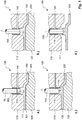
- Fig. 1 shows schematically and thus not to scale a section of a tool 100 according to the invention for producing a fiber-plastic composite component.
- the tool 100 comprises a tool lower part 120 and a tool upper part 110 movable for this purpose.
- the tool parts 110 and 120 are formed with corresponding mold sections 111 and 121 which form a cavity 130 when the tool is closed.
- the tool upper part 110 has at the point shown a vent hole 115 into which a vent line 140 opens.
- the vent line 140 is exemplified as transversely guided in the tool upper part 110 bore.
- a stamp-like, circular cylindrical pin 150 is arranged, which is longitudinally movably mounted in a arranged in the vent hole 115 bushing or sleeve 160.
- the operation of the pin 150 can be done by means of a hydraulic, pneumatic or electric motor drive.
- the pin 150 is formed with a flat end face 151.
- Fig. 1a shows the open state, wherein a fluid connection between the cavity 130 and the vent line 140 is made.
- Fig. 1b shows the closed state.
- the pin 150 thus acts as a valve spool. Furthermore, the pin 150 acts as a push-back pin and as an ejector pin, as explained below.
- Fig. 1 a shows the tool 100 after closing.
- 200 is inserted in the cavity 130 inserted fiber material.
- the retracted from the cavity 130 pin 150 releases the vent line 140, whereby the cavity 130 can be evacuated.
- the pin 150 will be placed in the Fig. 1 b shown neutral position, wherein the end face 151 of the pin 150 is plane-parallel with the Kavticianswandung (ie, the end face 151 forms a surface part of the Kavticianswandung).
- a resin material can be introduced into the cavity 130, for which purpose the tool 100 has injection nozzles or the like, not shown.
- the cavity 130 has at the vent hole 115 serving as a resin reservoir area (resin reservoir area) 135, which is structurally predetermined.
- the pin 150 can be advanced with a defined pressure force and / or with a defined travel and in this case retracted into the cavity 130, whereby the resin material located in the resin reservoir 135 is deliberately displaced. This is in Fig. 1c shown.
- the tool 100 After curing, the tool 100 is opened, so that the produced fiber-plastic composite component 300 can be removed.
- the pin 150 is actuated as an ejector pin, for which purpose it is moved further ahead. This is in Fig. 1d shown.
- the tool 100 may have a plurality and in particular a large number of vent bores 115 formed in this way with correspondingly formed pins 150, which may be designed identically or differently. These can be arranged both in the tool upper part 110 and in the lower tool part 120. Furthermore, these can be arranged largely freely (that is to say essentially not bound to constructive boundary conditions) and, in this case, in particular evenly distributed in the mold areas 111 and / or 121.
- the conduit 140 may be used instead of venting or evacuating the cavity 130 as a filling line for active gassing of the cavity 130, as explained above. Furthermore, it is conceivable that the line 140 is used both for evacuating and for gassing the cavity 130 (dual function). In both cases, the pin 150 can act as a valve spool.
Description
Die Erfindung betrifft ein Werkzeug zur Herstellung eines Faser-Kunststoff-Verbund-Bauteils, insbesondere zur Herstellung eines kohlenstofffaserverstärkten Kunststoffbauteils, gemäß der im Oberbegriff des Anspruchs 1 näher angegebenen Art.The invention relates to a tool for producing a fiber-plastic composite component, in particular for producing a carbon fiber reinforced plastic component, according to the more detail in the preamble of claim 1.
Ein gängiges Verfahren zur Herstellung eines Faser-Kunststoff-Verbund-Bauteils ist das RTM-Verfahren. Ein Werkzeug zur Durchführung eines RTM-Verfahrens besteht typischerweise aus zwei Werkzeugteilen (Formhälften), welche mit Formbereichen ausgebildet sind, die bei geschlossenem Werkzeug eine Kavität bilden. Bei geöffnetem Werkzeug wird in die Kavität ein Faserausgangsmaterial (Faserhalbzeug) eingelegt. Nach dem Schließen des Werkzeugs wird in der Kavität ein Vakuum erzeugt, indem diese über eine Entlüftungsleitung mit einer Vakuumquelle verbunden wird. Danach wird ein Harzmaterial (Matrixmaterial) in die Kavität eingebracht, welches dann unter Druck und/oder Wärme aushärtet. Zum Entformen des fertigen Bauteils wird das Werkzeug geöffnet und das Bauteil durch Auswerfer aus der Kavität herausgelöst.A common method for producing a fiber-plastic composite component is the RTM method. A tool for carrying out an RTM process typically consists of two tool parts (mold halves) which are formed with mold regions which form a cavity when the mold is closed. When the tool is open, a fiber raw material (semifinished fiber product) is inserted into the cavity. After closing the tool, a vacuum is created in the cavity by connecting it to a vacuum source via a vent line. Thereafter, a resin material (matrix material) is introduced into the cavity, which then cures under pressure and / or heat. To demold the finished component, the tool is opened and the component removed by ejector from the cavity.
In der
Aus der
Ein ähnliches Werkzeug, das ebenfalls in den Entlüftungsbohrungen angeordnete Auswerferstifte aufweist, die von einem Entlüftungsspalt umgeben sind, ist aus der
Aus der
Der Erfindung liegt die Aufgabe zugrunde, ein Werkzeug betreffender Art anzugeben, das gegenüber den aus dem Stand der Technik bekannten Werkzeugen wenigstens einen technologischen und/oder wirtschaftlichen Vorteil bietet.The invention has for its object to provide a tool of the kind that offers at least a technological and / or economic advantage over the tools known from the prior art.
Diese Aufgabe wird gelöst durch ein erfindungsgemäßes Werkzeug mit den Merkmalen des Anspruchs 1. Bevorzugte Weiterbildungen und Ausgestaltungen ergeben sich sowohl aus den abhängigen Ansprüchen als auch aus den nachfolgenden Erläuterungen.This object is achieved by an inventive tool with the features of claim 1. Preferred developments and refinements will become apparent both from the dependent claims and from the following explanations.
Das erfindungsgemäße Werkzeug umfasst wenigstens ein erstes Werkzeugteil und wenigstens ein zweites Werkzeugteil, die zum Öffnen und Schließen des Werkzeugs relativ zueinander verfahrbar sind und die zur Bildung einer Kavität mit korrespondierenden Formbereichen ausgebildet sind. Wenigstens eines der Werkzeugteile ist in seinem Formbereich (bzw. innerhalb der Kavität) mit wenigstens einer Entlüftungsbohrung ausgebildet und hat eine in die Entlüftungsbohrung mündende Entlüftungsleitung. In der Entlüftungsbohrung ist ein längsbeweglicher Stift (bzw. Bolzen) zum Öffnen und Schließen der in die Entlüftungsbohrung mündenden Entlüftungsleitung angeordnet , wobei dieser Stift gleichfalls auch als Auswerfer zum Entformen eines hergestellten Bauteils ausgebildet ist.The tool according to the invention comprises at least a first tool part and at least a second tool part, which are movable relative to each other for opening and closing the tool and which are formed to form a cavity with corresponding molding areas. At least one of the tool parts is formed in its molding area (or within the cavity) with at least one vent hole and has a vent line opening into the vent hole. In the vent hole a longitudinally movable pin (or bolt) is arranged for opening and closing the opening into the vent hole vent line, this pin is also also designed as an ejector for demolding a manufactured component.
Über die in die Entlüftungsbohrung mündende Entlüftungsleitung kann die Kavität entlüftet und bei Verbinden mit einer Vakuumquelle auch evakuiert werden.About the opening into the vent hole vent line, the cavity can be vented and also evacuated when connected to a vacuum source.
Der längsbeweglich in der Entlüftungsbohrung geführte Stift (bzw. Bolzen) hat somit zumindest eine Doppelfunktion, indem dieser einerseits als Ventilschieber und andererseits als Auswerfer bzw. Auswerferstift benutzbar ist. Das Werkzeug kann somit gegenüber den aus dem Stand der Technik bekannten Werkzeugen einfacher konstruiert und aufgebaut werden. Dadurch können Werkzeuggewicht und Herstellungskosten eingespart werden. Auch der Fertigungsbetrieb mit einem erfindungsgemäßen Werkzeug erweist sich als weniger aufwändig. Erfindungsgemäß ist vorgesehen, dass der Stift in einer in der Entlüftungsbohrung angeordneten Buchse längsbeweglich (bzw. in axialer Richtung) geführt ist. Bei der Buchse kann es sich bspw. um eine metallische Buchse handeln, die in die Entlüftungsbohrung eingeschraubt, eingepresst und/oder eingeklebt ist. Der Stift und die Buchse sind mit einer definierten Passung ausgebildet, um eine störungsfreie Führung und einwandfreie Abdichtung zu gewährleisten.The longitudinally movably guided in the vent hole pin (or bolt) thus has at least a double function by this one hand, as a valve spool and on the other hand as an ejector or ejector pin is usable. The tool can thus be constructed and constructed more easily than the tools known from the prior art. As a result, tool weight and manufacturing costs can be saved. Also, the manufacturing operation with a tool according to the invention proves to be less expensive. According to the invention, provision is made for the pin to be guided longitudinally movably (or in the axial direction) in a bushing arranged in the venting bore. The bush can be, for example, a metallic bush, which is screwed, pressed and / or glued into the vent hole. The pin and the socket are designed with a defined fit to ensure trouble-free guidance and proper sealing.
Der Stift ist an seinem der Kavität zugewandten axialen Ende bevorzugt mit einer planen (d. h. ebenen und glatten) Stirnfläche ausgebildet. Bevorzugt handelt es sich um einen metallischen Stift.The pin is preferably formed at its axial end facing the cavity with a flat (i.e., flat and smooth) end face. Preferably, it is a metallic pin.
Besonders bevorzugt ist vorgesehen, dass die erfindungsgemäß ausgebildete Entlüftungsbohrung in einem Harzreservoirbereich angeordnet ist, so dass der Stift auch als Nachdrückstift verwendet werden kann, um einen lokalen Kavitätsinnendruck erzeugen zu können. Hierzu wird der Stift definiert, bspw. mit vorgegebener Druckkraft, in die Kavität eingefahren. Nachdrückstifte, mit denen, insbesondere während des Aushärtens, ein lokaler Kavitätsinnendruck (Forminnendruck) erzeugt werden kann, bspw. um Schwindungen in Bauteilbereichen mit Materialanhäufungen zu kompensieren und/oder in kritischen Bauteilbereichen eine bessere Formabbildung zu erhalten, sind als solche aus dem Stand der Technik bekannt.Particularly preferably, it is provided that the vent hole formed according to the invention is arranged in a resin reservoir area, so that the pin can also be used as a push-back pin in order to be able to generate a local cavity internal pressure. For this purpose, the pin is defined, for example, with a predetermined compressive force, retracted into the cavity. Nachdrückstifte with which, especially during curing, a local cavity internal pressure (internal mold pressure) can be generated, for example. To compensate for shrinkage in component areas with accumulations of material and / or to obtain a better shape imaging in critical component areas are as such from the prior art known.
Das erfindungsgemäße Werkzeug kann eine Vielzahl von Entlüftungsbohrungen und darin angeordneten längsbeweglichen Stiften aufweisen, wobei die Stifte miteinander gekoppelt und synchron (d. h. gleichzeitig) betätigbar sind. Eine Kopplung der Stifte kann bspw. durch eine gemeinsame Betätigungseinrichtung erfolgen.The tool of the present invention may have a plurality of vent holes and longitudinally movable pins disposed therein, the pins being coupled together and operable synchronously (i.e., simultaneously). A coupling of the pins can, for example, be done by a common actuator.
Alternativ kann vorgesehen sein, dass das erfindungsgemäße Werkzeug eine Vielzahl von Entlüftungsbohrungen und darin angeordneten längsbeweglichen Stiften aufweist, wobei die Stifte unabhängig voneinander und insbesondere einzeln betätigbar sind. Besonders bevorzugt ist vorgesehen, dass jeder Stift einzeln betätigbar ist, wozu jedem Stift eine Betätigungseinrichtung zugeordnet sein kann. Dadurch kann sowohl das Entlüften oder das Evakuieren (Vakuumieren) der Kavität als auch das Entformen des Bauteils an konkrete Erfordernisse angepasst werden, was sowohl die zeitliche Steuerung der Stifte als auch die erzeugten Stellkräfte und Stellbewegungen (Stellwege) umfassen kann. Eine Betätigungseinrichtung kann bspw. ein im Werkzeug verbauter oder außen am Werkzeug angebauter hydraulischer, pneumatischer oder elektromotorischer Antrieb sein.Alternatively it can be provided that the tool according to the invention has a plurality of vent holes and arranged therein longitudinally movable pins, wherein the pins are independently and in particular individually operable. It is particularly preferred that each pin can be actuated individually, to which each pin an actuating device can be assigned. As a result, both the venting or evacuation (vacuuming) of the cavity and the demoulding of the component can be adapted to specific requirements, which may include both the timing of the pins and the generated actuating forces and actuating movements (travel paths). An actuating device can be, for example, a hydraulic, pneumatic or electromotive drive mounted in the tool or externally mounted on the tool.
Das erfindungsgemäße Werkzeug kann ferner auch eine in wenigstens eine Entlüftungsbohrung mündende Füllleitung zum Begasen der Kavität aufweisen. Durch ein über diese Füllleitung in die Kavität eingebrachtes Gas kann ein, gegebenenfalls nur lokal wirksamer, Kavitätsinnendruck erzeugt und/oder ein geschäumtes Bauteil hergestellt werden. Es ist vorgesehen, dass der in dieser Entlüftungsbohrung längsbeweglich angeordnete Stift auch zum Öffnen und Schließen der Füllleitung dient. Besonders bevorzugt ist nur eine Leitung vorgesehen, die wahlweise als Entlüftungsleitung oder als Füllleitung dient.The tool according to the invention may also have a filling line for venting the cavity which opens into at least one ventilation bore. By means of a gas introduced into the cavity via this filling line, it is possible to produce an internal cavity pressure which is possibly only locally effective, and / or to produce a foamed component. It is envisaged that the longitudinally movably arranged in this vent hole pin also serves to open and close the filling line. Particularly preferred only one line is provided which serves either as a vent line or as a filling line.
Bei dem erfindungsgemäßen Werkzeug handelt es sich insbesondere um ein RTM-Werkzeug zur Herstellung eines Faser-Kunststoff-Verbund-Bauteils nach dem RTM-Verfahren, wie eingangs erläutert, wozu dieses Einrichtungen, wie bspw. Einspritzdüsen, umfasst, die bei geschlossenem Werkzeug das Einbringen eines Harzmaterials in die Kavität ermöglichen.The tool according to the invention is, in particular, an RTM tool for producing a fiber-plastic composite component according to the RTM method, as explained in the introduction, for which purpose this device, such as injection nozzles, comprises the insertion of the tool when the tool is closed allow a resin material in the cavity.
Bei dem erfindungsgemäßen Werkzeug kann es sich auch um ein Nasspresswerkzeug zur Herstellung eines Faser-Kunststoff-Verbund-Bauteils nach dem Nasspress-Verfahren, wie eingangs erläutert, handeln. Ein solches Werkzeug kommt ohne RTM-verfahrensspezifische Einrichtungen aus. Mit einem solchen erfindungsgemäßen Werkzeug können in vorteilhafter Weise aufgrund der möglichen Evakuierung der Kavität auch beim Nasspressen definierte Kavitätsinnendrücke erzeugt werden (was bislang kaum möglich ist), wodurch sich auch mit dem Nasspress-Verfahren Faser-Kunststoff-Verbund-Bauteile mit hoher Bauteilqualität herstellen lassen.The tool according to the invention may also be a wet pressing tool for producing a fiber-plastic composite component by the wet-pressing method, as explained above. Such a tool does not require RTM process-specific facilities. With such a tool according to the invention can be generated in an advantageous manner due to the possible evacuation of the cavity also in wet pressing Kavitäteninnendrücke (which is hardly possible so far), which can be produced with high quality component also with the wet-pressing process fiber-plastic composite components ,
Die Erfindung wird nachfolgend anhand der Zeichnung beispielhaft und in nicht einschränkender Weise näher erläutert. Hierbei können die in der Zeichnung gezeigten und/oder nachfolgend erläuterten Merkmale, unabhängig von konkreten Merkmalskombinationen, allgemeine Merkmale der Erfindung sein. In der Zeichnung zeigt
- Fig. 1
- in mehreren schematischen Schnittansichten einen Ausschnitt aus einem erfindungsgemäßen Werkzeug, wobei verschiedene Phasen eines Herstellvorgangs dargestellt sind.
- Fig. 1
- in several schematic sectional views a section of a tool according to the invention, wherein different phases of a manufacturing process are shown.
In der Entlüftungsbohrung 115 ist ein stempelartiger, kreiszylindrischer Stift 150 angeordnet, der längsbeweglich in einer in der Entlüftungsbohrung 115 angeordneten Buchse bzw. Hülse 160 gelagert ist. Die Betätigung des Stifts 150 kann mit Hilfe eines hydraulischen, pneumatischen oder elektromotorischen Antriebs erfolgen. Der Stift 150 ist mit einer planen Stirnfläche 151 ausgebildet.In the
Durch Längsbewegen des Stifts 150 entlang der Längsachse L kann die Entlüftungsleitung 140 geöffnet und geschlossen werden.
Noch bei geschlossenem Werkzeug 100 erfolgt die Aushärtung des in die Kavität eingebrachten Harzmaterials unter Druck- und Wärmeeinwirkung, wobei das Harzmaterial zusammen mit dem Fasermaterial 200 ein Faser-Kunststoff-Verbund-Bauteil 300 bildet. Die Kavität 130 weist an der Entlüftungsbohrung 115 einen als Harzreservoir dienenden Bereich (Harzreservoirbereich) 135 auf, der konstruktiv vorgegeben ist. In der so genannten Nachdruckphase während des Aushärtens kann der Stift 150 mit definierter Druckkraft und/oder mit definiertem Stellweg vorgefahren und hierbei in die Kavität 130 eingefahren werden, wodurch das im Harzreservoir 135 befindliche Harzmaterial gezielt verdrängt wird. Dies ist in
Nach dem Aushärten wird das Werkzeug 100 geöffnet, so dass das hergestellte Faser-Kunststoff-Verbund-Bauteil 300 entnommen werden kann. Zur Entformung des Bauteils 300 wird der Stift 150 als Auswerferstift betätigt, wozu dieser noch weiter vorgefahren wird. Dies ist in
Das Werkzeug 100 kann mehrere und insbesondere auch eine große Anzahl derart ausgebildeter Entlüftungsbohrungen 115 mit entsprechend ausgebildeten Stiften 150 aufweisen, die identisch oder unterschiedlich gestaltet sein können. Diese können sowohl im Werkzeugoberteil 110 als auch im Werkzeugunterteil 120 angeordnet sein. Ferner können diese weitgehend frei (d. h. im Wesentlichen nicht an konstruktive Randbedingungen gebunden) und hierbei insbesondere auch gleichmäßig verteilt in den Formbereichen 111 und/oder 121 angeordnet werden.The
Die Leitung 140 kann anstatt zur Entlüftung oder Evakuierung der Kavität 130 auch als Füllleitung zur aktiven Begasung der Kavität 130 verwendet werden, wie obenstehend erläutert. Ferner ist denkbar, dass die Leitung 140 sowohl zum Evakuieren als auch zum Begasen der Kavität 130 verwendet wird (Doppelfunktion). In beiden Fällen kann der Stift 150 als Ventilschieber fungieren.The
- 100100
- WerkzeugTool
- 110110
- Werkzeugoberteil (obere Werkzeughälfte)Tool upper part (upper mold half)
- 111111
- Formbereichshape area
- 115115
- Entlüftungsbohrungvent hole
- 120120
- Werkzeugunterteil (untere Werkzeughälfte)Tool lower part (lower tool half)
- 121121
- Formbereichshape area
- 130130
- Kavitätcavity
- 135135
- Harzreservoirresin reservoir
- 140140
- Leitungmanagement
- 150150
- Stift (Bolzen)Pin (bolt)
- 151151
- Stirnflächeface
- 160160
- BuchseRifle
- 200200
- Fasermaterialfiber material
- 300300
- Bauteilcomponent
- LL
- Längsachselongitudinal axis
Claims (9)
- A mould (100) for producing a fibre-reinforced plastics material component (300), especially for producing a carbon fibre reinforced plastics material component, comprising:- at least a first mould part (110) and at least a second mould part (120) which are movable relative to each other for opening and closing the mould (100) and which are formed with corresponding moulding regions (111, 121) to form a cavity (130);- at least one ventilation bore (115) which is formed in the moulding region (111) of at least one of the mould parts (110); and- a ventilation line (140) opening into the ventilation bore (115); wherein a longitudinally mobile dual-function pin (150) is arranged in the ventilation bore (115), which pin is formed as a valve slider for opening and closing the ventilation line (140) which opens into the ventilation bore (115) and at the same time is also formed as an ejector for demoulding a component (300) which is produced,characterised in that
a bush (160) is arranged in the ventilation bore (115), into which bush the ventilation line (140) opens and in which the pin (150) is guided in longitudinally mobile manner. - A mould (100) according to Claim 1,
characterised in that
the pin (150) is formed with a planar end face (151) on its axial end facing the cavity. - A mould (100) according to one of the preceding claims,
characterised in that
the ventilation bore (115) is arranged in a resin reservoir region (135), so that the pin (150) can also be used as a holding-pressure pin, in order to generate a local internal cavity pressure. - A mould (100) according to one of the preceding Claims 1 to 3,
characterised in that
it has a plurality of ventilation bores (115) and longitudinally mobile pins (150) arranged therein, the pins (150) being coupled together and being able to be actuated synchronously. - A mould (100) according to one of the preceding Claims 1 to 3,
characterised in that
it has a plurality of ventilation bores (115) and longitudinally mobile pins (150) arranged therein, the pins (150) being able to be actuated independently of each other. - A mould according to Claim 5,
characterised in that
each pin (150) can be actuated individually, for which purpose an actuating means is associated with each of the pins (150). - A mould (100) according to one of the preceding claims,
characterised in that
it has a filling line opening into at least one ventilation bore (115) for supplying gas to the cavity (130), with the pin (150) arranged in longitudinally mobile manner in this ventilation bore (115) likewise being formed for opening and closing the filling line. - A mould (100) according to one of the preceding Claims 1 to 7,
characterised in that
it is an RTM mould. - A mould (100) according to one of the preceding Claims 1 to 7,
characterised in that
it is a wet pressing mould.
Applications Claiming Priority (2)
| Application Number | Priority Date | Filing Date | Title |
|---|---|---|---|
| DE102013207668.1A DE102013207668A1 (en) | 2013-04-26 | 2013-04-26 | Tool for producing a fiber-plastic composite component with at least one vent hole and arranged therein Auswerferstift |
| PCT/EP2014/056927 WO2014173671A2 (en) | 2013-04-26 | 2014-04-07 | Tool for producing a fiber/plastic composite component, comprising at least one ventilating bore and ejector pin arranged in the bore |
Publications (2)
| Publication Number | Publication Date |
|---|---|
| EP2988913A2 EP2988913A2 (en) | 2016-03-02 |
| EP2988913B1 true EP2988913B1 (en) | 2017-08-16 |
Family
ID=50478386
Family Applications (1)
| Application Number | Title | Priority Date | Filing Date |
|---|---|---|---|
| EP14716550.0A Active EP2988913B1 (en) | 2013-04-26 | 2014-04-07 | Mould for producing a composite component, comprising at least one ventilating bore and ejector pin arranged in the bore |
Country Status (3)
| Country | Link |
|---|---|
| EP (1) | EP2988913B1 (en) |
| DE (1) | DE102013207668A1 (en) |
| WO (1) | WO2014173671A2 (en) |
Families Citing this family (7)
| Publication number | Priority date | Publication date | Assignee | Title |
|---|---|---|---|---|
| DE102014223110A1 (en) * | 2014-11-12 | 2016-05-12 | Bayerische Motoren Werke Aktiengesellschaft | Mold for the production of molded parts with fiber-reinforced plastic material and method for producing the molded parts |
| FR3029449B1 (en) * | 2014-12-03 | 2017-10-13 | Pole De Plasturgie De Lest | MOLDING DEVICE FOR MANUFACTURING COMPOSITE MATERIAL PARTS FROM LIQUID POLYMER RESIN. |
| DE102015008566B4 (en) * | 2015-07-02 | 2017-03-30 | Audi Ag | Method for increasing a setting strength of a composite component, composite component and apparatus for producing a composite component |
| DE102015016784B4 (en) * | 2015-12-23 | 2018-12-20 | Fm Marketing Gmbh | Monolithic remote control and method of making the same |
| DE202016006356U1 (en) | 2016-10-12 | 2016-10-26 | Engel Austria Gmbh | Movable tool element |
| DE102017006050B4 (en) | 2017-06-27 | 2021-05-06 | Audi Ag | Process for the production of an FRP component with local compression and process for the production of a component composite |
| DE102018100177A1 (en) * | 2018-01-05 | 2019-07-11 | Webasto SE | Device for injection molding a plastic molding |
Citations (2)
| Publication number | Priority date | Publication date | Assignee | Title |
|---|---|---|---|---|
| JPS61152421A (en) * | 1984-12-27 | 1986-07-11 | Fanuc Ltd | Mechanism for evacuating inside of mold for injection molding machine |
| JPH06262652A (en) * | 1993-03-11 | 1994-09-20 | Japan Steel Works Ltd:The | Injection molding method and injection mold |
Family Cites Families (14)
| Publication number | Priority date | Publication date | Assignee | Title |
|---|---|---|---|---|
| JPS61235108A (en) * | 1985-04-12 | 1986-10-20 | Daiichi Kasei Kk | Structure of ejector mechanism for metal mold |
| US4874308A (en) * | 1988-04-04 | 1989-10-17 | Atlas Gary N | Vacuum assisted transfer mold and vent pin |
| JPH05104530A (en) * | 1991-10-21 | 1993-04-27 | Matsushita Electric Works Ltd | Mold |
| JPH08197592A (en) * | 1995-01-30 | 1996-08-06 | Ikegami Kanagata Kogyo Kk | Ejection pin |
| DE19813105C2 (en) | 1998-03-25 | 2001-03-01 | Daimler Chrysler Ag | Process for the production of fiber composite components |
| DE19850462C2 (en) | 1998-11-02 | 2001-02-08 | Fritzmeier Composite Gmbh & Co | Method for producing a molded plastic part, tool for carrying out the method and molded part produced with it |
| DE20002110U1 (en) * | 2000-02-07 | 2000-05-04 | Louis Brinkmann Formenbau Gmbh | Mold for the production of plastic parts |
| JP3932938B2 (en) * | 2002-03-20 | 2007-06-20 | 双葉電子工業株式会社 | Injection mold and injection mold pin |
| JP2006326974A (en) * | 2005-05-25 | 2006-12-07 | Toshiba Corp | Mold assembly |
| US20090134549A1 (en) * | 2005-12-12 | 2009-05-28 | Hiroaki Yamamoto | Molding Apparatus |
| ES2348885B1 (en) * | 2010-09-29 | 2011-10-14 | Comercial De Utiles Y Moldes S.A. | PLASTIC INJECTION MOLD WITH EXTRACTION OF THE INTERNAL AIR AND PROCEDURE OF EXTRACTION OF THE AIR CARRIED OUT WITH SUCH MOLD. |
| DE102010052180A1 (en) | 2010-11-22 | 2012-05-24 | Daimler Ag | Injection molding tool used in manufacture of composite plastic components for motor vehicle, has tool cooling device that is arranged on mold sections and is supplied with cooling medium through conveying device |
| DE102011050976A1 (en) | 2011-06-09 | 2012-12-13 | Georg Fritzmeier Gmbh & Co. Kg | Ejection device for ejecting mold e.g. sheet molding compound (SMC) mold, has ejector pin which is provided in transverse direction with respect to longitudinal axis for ejecting mold |
| DE102011080054A1 (en) * | 2011-07-28 | 2013-01-31 | Zf Friedrichshafen Ag | Injection head and ejector of an injection device |
-
2013
- 2013-04-26 DE DE102013207668.1A patent/DE102013207668A1/en not_active Ceased
-
2014
- 2014-04-07 WO PCT/EP2014/056927 patent/WO2014173671A2/en active Application Filing
- 2014-04-07 EP EP14716550.0A patent/EP2988913B1/en active Active
Patent Citations (2)
| Publication number | Priority date | Publication date | Assignee | Title |
|---|---|---|---|---|
| JPS61152421A (en) * | 1984-12-27 | 1986-07-11 | Fanuc Ltd | Mechanism for evacuating inside of mold for injection molding machine |
| JPH06262652A (en) * | 1993-03-11 | 1994-09-20 | Japan Steel Works Ltd:The | Injection molding method and injection mold |
Non-Patent Citations (2)
| Title |
|---|
| DATABASE WPI Week 198634, Derwent World Patents Index; AN 1986-221872 * |
| DATABASE WPI Week 199442, Derwent World Patents Index; AN 1994-337824 * |
Also Published As
| Publication number | Publication date |
|---|---|
| WO2014173671A3 (en) | 2015-01-08 |
| DE102013207668A1 (en) | 2014-10-30 |
| EP2988913A2 (en) | 2016-03-02 |
| WO2014173671A2 (en) | 2014-10-30 |
Similar Documents
| Publication | Publication Date | Title |
|---|---|---|
| EP2988913B1 (en) | Mould for producing a composite component, comprising at least one ventilating bore and ejector pin arranged in the bore | |
| EP2524796B1 (en) | Method and installation for producing shell like plastic parts | |
| EP2089207B1 (en) | Method and device for producing a composite component, in particular comprising an injection-moulded part with a polyurethane coating | |
| EP2176059B1 (en) | Method and device for producing a reinforced composite product | |
| EP2399726B1 (en) | Moulding tool for producing fibre compound components and method for producing fibre compound components with such a moulding tool | |
| AT517754B1 (en) | Arrangement for consolidating thermoplastic semi-finished products | |
| WO2012171548A1 (en) | Draping and compression molding tool, and method for producing a preform and a fiber-plastic composite component | |
| EP0824057A1 (en) | Method and apparatus for manufacturing plastic injection moulded articles | |
| EP0074473B1 (en) | Method of and apparatus for manufacturing moulded plastics pieces or articles | |
| DE102012010469B4 (en) | Process for the production of fiber-reinforced components | |
| DE10157655A1 (en) | Impregnated compound fiber structures are produced using a fiber preform held in a cavity, where the two sections forming the cavity are moved apart to form gaps for resin to flow in with a vacuum | |
| DE102012102594B4 (en) | Method for producing molded parts from plastic | |
| EP3036090B1 (en) | Mould system and method for producing components by the rtm method | |
| DE102009060526A1 (en) | Press system for manufacturing shaped parts from fiber composite material for body parts of vehicle, has filling device filling molding material in form area and moved relative to presses for filling individual forming tool | |
| EP0767760B2 (en) | Method of producing glass mouldings in a press, and a press particularly suitable for use with the method | |
| DE112015006020T5 (en) | Molds and method for molding a plastic sheet | |
| DE102011057033A1 (en) | Press tool e.g. sheet molding compound (SMC) press tool for manufacturing mold portion such as outer casing of motor vehicle, has die that is biased with ram in direction of pressing position, if tool is opened in advance position | |
| DE102013003538A1 (en) | Producing component, preferably a component for automotive vehicle with core structure and cover layer, comprises producing finally produced core structure and applying cover layer by laminating strip material on core structure | |
| DE102013109490A1 (en) | Hydraulic cycle press | |
| DE102014005629B4 (en) | Mold for producing fiber-reinforced components | |
| DE102010006651B4 (en) | Mold for making molded parts from e.g. Plastic, in particular of a fiber composite material | |
| DE102012106936A1 (en) | Integrated contact heating for thermoplastic bonded mats in the injection mold | |
| EP2029346B1 (en) | Positioning device | |
| DE102013209558A1 (en) | Press tool and method for pressing unidirectional fiber rovings | |
| DE102021109686A1 (en) | Mobile processing device with tool storage |
Legal Events
| Date | Code | Title | Description |
|---|---|---|---|
| PUAI | Public reference made under article 153(3) epc to a published international application that has entered the european phase |
Free format text: ORIGINAL CODE: 0009012 |
|
| 17P | Request for examination filed |
Effective date: 20150925 |
|
| AK | Designated contracting states |
Kind code of ref document: A2 Designated state(s): AL AT BE BG CH CY CZ DE DK EE ES FI FR GB GR HR HU IE IS IT LI LT LU LV MC MK MT NL NO PL PT RO RS SE SI SK SM TR |
|
| AX | Request for extension of the european patent |
Extension state: BA ME |
|
| DAX | Request for extension of the european patent (deleted) | ||
| 17Q | First examination report despatched |
Effective date: 20161121 |
|
| GRAP | Despatch of communication of intention to grant a patent |
Free format text: ORIGINAL CODE: EPIDOSNIGR1 |
|
| INTG | Intention to grant announced |
Effective date: 20170425 |
|
| RIN1 | Information on inventor provided before grant (corrected) |
Inventor name: HEIM, BERNHARD Inventor name: THEINERT, JOERG Inventor name: KRULL, SEBASTIAN |
|
| GRAS | Grant fee paid |
Free format text: ORIGINAL CODE: EPIDOSNIGR3 |
|
| GRAA | (expected) grant |
Free format text: ORIGINAL CODE: 0009210 |
|
| AK | Designated contracting states |
Kind code of ref document: B1 Designated state(s): AL AT BE BG CH CY CZ DE DK EE ES FI FR GB GR HR HU IE IS IT LI LT LU LV MC MK MT NL NO PL PT RO RS SE SI SK SM TR |
|
| REG | Reference to a national code |
Ref country code: GB Ref legal event code: FG4D Free format text: NOT ENGLISH |
|
| REG | Reference to a national code |
Ref country code: CH Ref legal event code: EP |
|
| REG | Reference to a national code |
Ref country code: IE Ref legal event code: FG4D Free format text: LANGUAGE OF EP DOCUMENT: GERMAN |
|
| REG | Reference to a national code |
Ref country code: AT Ref legal event code: REF Ref document number: 918620 Country of ref document: AT Kind code of ref document: T Effective date: 20170915 |
|
| REG | Reference to a national code |
Ref country code: DE Ref legal event code: R096 Ref document number: 502014005059 Country of ref document: DE |
|
| REG | Reference to a national code |
Ref country code: NL Ref legal event code: MP Effective date: 20170816 |
|
| REG | Reference to a national code |
Ref country code: LT Ref legal event code: MG4D |
|
| PG25 | Lapsed in a contracting state [announced via postgrant information from national office to epo] |
Ref country code: SE Free format text: LAPSE BECAUSE OF FAILURE TO SUBMIT A TRANSLATION OF THE DESCRIPTION OR TO PAY THE FEE WITHIN THE PRESCRIBED TIME-LIMIT Effective date: 20170816 Ref country code: NL Free format text: LAPSE BECAUSE OF FAILURE TO SUBMIT A TRANSLATION OF THE DESCRIPTION OR TO PAY THE FEE WITHIN THE PRESCRIBED TIME-LIMIT Effective date: 20170816 Ref country code: NO Free format text: LAPSE BECAUSE OF FAILURE TO SUBMIT A TRANSLATION OF THE DESCRIPTION OR TO PAY THE FEE WITHIN THE PRESCRIBED TIME-LIMIT Effective date: 20171116 Ref country code: FI Free format text: LAPSE BECAUSE OF FAILURE TO SUBMIT A TRANSLATION OF THE DESCRIPTION OR TO PAY THE FEE WITHIN THE PRESCRIBED TIME-LIMIT Effective date: 20170816 Ref country code: LT Free format text: LAPSE BECAUSE OF FAILURE TO SUBMIT A TRANSLATION OF THE DESCRIPTION OR TO PAY THE FEE WITHIN THE PRESCRIBED TIME-LIMIT Effective date: 20170816 |
|
| PG25 | Lapsed in a contracting state [announced via postgrant information from national office to epo] |
Ref country code: IS Free format text: LAPSE BECAUSE OF FAILURE TO SUBMIT A TRANSLATION OF THE DESCRIPTION OR TO PAY THE FEE WITHIN THE PRESCRIBED TIME-LIMIT Effective date: 20171216 Ref country code: GR Free format text: LAPSE BECAUSE OF FAILURE TO SUBMIT A TRANSLATION OF THE DESCRIPTION OR TO PAY THE FEE WITHIN THE PRESCRIBED TIME-LIMIT Effective date: 20171117 Ref country code: BG Free format text: LAPSE BECAUSE OF FAILURE TO SUBMIT A TRANSLATION OF THE DESCRIPTION OR TO PAY THE FEE WITHIN THE PRESCRIBED TIME-LIMIT Effective date: 20171116 Ref country code: ES Free format text: LAPSE BECAUSE OF FAILURE TO SUBMIT A TRANSLATION OF THE DESCRIPTION OR TO PAY THE FEE WITHIN THE PRESCRIBED TIME-LIMIT Effective date: 20170816 Ref country code: PL Free format text: LAPSE BECAUSE OF FAILURE TO SUBMIT A TRANSLATION OF THE DESCRIPTION OR TO PAY THE FEE WITHIN THE PRESCRIBED TIME-LIMIT Effective date: 20170816 Ref country code: LV Free format text: LAPSE BECAUSE OF FAILURE TO SUBMIT A TRANSLATION OF THE DESCRIPTION OR TO PAY THE FEE WITHIN THE PRESCRIBED TIME-LIMIT Effective date: 20170816 Ref country code: RS Free format text: LAPSE BECAUSE OF FAILURE TO SUBMIT A TRANSLATION OF THE DESCRIPTION OR TO PAY THE FEE WITHIN THE PRESCRIBED TIME-LIMIT Effective date: 20170816 |
|
| REG | Reference to a national code |
Ref country code: FR Ref legal event code: PLFP Year of fee payment: 5 |
|
| PG25 | Lapsed in a contracting state [announced via postgrant information from national office to epo] |
Ref country code: RO Free format text: LAPSE BECAUSE OF FAILURE TO SUBMIT A TRANSLATION OF THE DESCRIPTION OR TO PAY THE FEE WITHIN THE PRESCRIBED TIME-LIMIT Effective date: 20170816 Ref country code: DK Free format text: LAPSE BECAUSE OF FAILURE TO SUBMIT A TRANSLATION OF THE DESCRIPTION OR TO PAY THE FEE WITHIN THE PRESCRIBED TIME-LIMIT Effective date: 20170816 Ref country code: CZ Free format text: LAPSE BECAUSE OF FAILURE TO SUBMIT A TRANSLATION OF THE DESCRIPTION OR TO PAY THE FEE WITHIN THE PRESCRIBED TIME-LIMIT Effective date: 20170816 |
|
| REG | Reference to a national code |
Ref country code: DE Ref legal event code: R097 Ref document number: 502014005059 Country of ref document: DE |
|
| PG25 | Lapsed in a contracting state [announced via postgrant information from national office to epo] |
Ref country code: EE Free format text: LAPSE BECAUSE OF FAILURE TO SUBMIT A TRANSLATION OF THE DESCRIPTION OR TO PAY THE FEE WITHIN THE PRESCRIBED TIME-LIMIT Effective date: 20170816 Ref country code: SK Free format text: LAPSE BECAUSE OF FAILURE TO SUBMIT A TRANSLATION OF THE DESCRIPTION OR TO PAY THE FEE WITHIN THE PRESCRIBED TIME-LIMIT Effective date: 20170816 Ref country code: SM Free format text: LAPSE BECAUSE OF FAILURE TO SUBMIT A TRANSLATION OF THE DESCRIPTION OR TO PAY THE FEE WITHIN THE PRESCRIBED TIME-LIMIT Effective date: 20170816 |
|
| PLBE | No opposition filed within time limit |
Free format text: ORIGINAL CODE: 0009261 |
|
| STAA | Information on the status of an ep patent application or granted ep patent |
Free format text: STATUS: NO OPPOSITION FILED WITHIN TIME LIMIT |
|
| 26N | No opposition filed |
Effective date: 20180517 |
|
| PG25 | Lapsed in a contracting state [announced via postgrant information from national office to epo] |
Ref country code: SI Free format text: LAPSE BECAUSE OF FAILURE TO SUBMIT A TRANSLATION OF THE DESCRIPTION OR TO PAY THE FEE WITHIN THE PRESCRIBED TIME-LIMIT Effective date: 20170816 |
|
| PG25 | Lapsed in a contracting state [announced via postgrant information from national office to epo] |
Ref country code: MT Free format text: LAPSE BECAUSE OF FAILURE TO SUBMIT A TRANSLATION OF THE DESCRIPTION OR TO PAY THE FEE WITHIN THE PRESCRIBED TIME-LIMIT Effective date: 20170816 |
|
| PG25 | Lapsed in a contracting state [announced via postgrant information from national office to epo] |
Ref country code: MC Free format text: LAPSE BECAUSE OF FAILURE TO SUBMIT A TRANSLATION OF THE DESCRIPTION OR TO PAY THE FEE WITHIN THE PRESCRIBED TIME-LIMIT Effective date: 20170816 |
|
| REG | Reference to a national code |
Ref country code: CH Ref legal event code: PL |
|
| REG | Reference to a national code |
Ref country code: BE Ref legal event code: MM Effective date: 20180430 |
|
| REG | Reference to a national code |
Ref country code: IE Ref legal event code: MM4A |
|
| PG25 | Lapsed in a contracting state [announced via postgrant information from national office to epo] |
Ref country code: LU Free format text: LAPSE BECAUSE OF NON-PAYMENT OF DUE FEES Effective date: 20180407 |
|
| PG25 | Lapsed in a contracting state [announced via postgrant information from national office to epo] |
Ref country code: LI Free format text: LAPSE BECAUSE OF NON-PAYMENT OF DUE FEES Effective date: 20180430 Ref country code: CH Free format text: LAPSE BECAUSE OF NON-PAYMENT OF DUE FEES Effective date: 20180430 Ref country code: BE Free format text: LAPSE BECAUSE OF NON-PAYMENT OF DUE FEES Effective date: 20180430 |
|
| PG25 | Lapsed in a contracting state [announced via postgrant information from national office to epo] |
Ref country code: IE Free format text: LAPSE BECAUSE OF NON-PAYMENT OF DUE FEES Effective date: 20180407 |
|
| PG25 | Lapsed in a contracting state [announced via postgrant information from national office to epo] |
Ref country code: TR Free format text: LAPSE BECAUSE OF FAILURE TO SUBMIT A TRANSLATION OF THE DESCRIPTION OR TO PAY THE FEE WITHIN THE PRESCRIBED TIME-LIMIT Effective date: 20170816 |
|
| PG25 | Lapsed in a contracting state [announced via postgrant information from national office to epo] |
Ref country code: PT Free format text: LAPSE BECAUSE OF FAILURE TO SUBMIT A TRANSLATION OF THE DESCRIPTION OR TO PAY THE FEE WITHIN THE PRESCRIBED TIME-LIMIT Effective date: 20170816 |
|
| PG25 | Lapsed in a contracting state [announced via postgrant information from national office to epo] |
Ref country code: MK Free format text: LAPSE BECAUSE OF NON-PAYMENT OF DUE FEES Effective date: 20170816 Ref country code: CY Free format text: LAPSE BECAUSE OF FAILURE TO SUBMIT A TRANSLATION OF THE DESCRIPTION OR TO PAY THE FEE WITHIN THE PRESCRIBED TIME-LIMIT Effective date: 20170816 Ref country code: HR Free format text: LAPSE BECAUSE OF FAILURE TO SUBMIT A TRANSLATION OF THE DESCRIPTION OR TO PAY THE FEE WITHIN THE PRESCRIBED TIME-LIMIT Effective date: 20170816 Ref country code: HU Free format text: LAPSE BECAUSE OF FAILURE TO SUBMIT A TRANSLATION OF THE DESCRIPTION OR TO PAY THE FEE WITHIN THE PRESCRIBED TIME-LIMIT; INVALID AB INITIO Effective date: 20140407 |
|
| PG25 | Lapsed in a contracting state [announced via postgrant information from national office to epo] |
Ref country code: AL Free format text: LAPSE BECAUSE OF FAILURE TO SUBMIT A TRANSLATION OF THE DESCRIPTION OR TO PAY THE FEE WITHIN THE PRESCRIBED TIME-LIMIT Effective date: 20170816 |
|
| REG | Reference to a national code |
Ref country code: AT Ref legal event code: MM01 Ref document number: 918620 Country of ref document: AT Kind code of ref document: T Effective date: 20190407 |
|
| PG25 | Lapsed in a contracting state [announced via postgrant information from national office to epo] |
Ref country code: AT Free format text: LAPSE BECAUSE OF NON-PAYMENT OF DUE FEES Effective date: 20190407 |
|
| P01 | Opt-out of the competence of the unified patent court (upc) registered |
Effective date: 20230502 |
|
| PGFP | Annual fee paid to national office [announced via postgrant information from national office to epo] |
Ref country code: IT Payment date: 20230428 Year of fee payment: 10 Ref country code: FR Payment date: 20230417 Year of fee payment: 10 Ref country code: DE Payment date: 20230411 Year of fee payment: 10 |
|
| PGFP | Annual fee paid to national office [announced via postgrant information from national office to epo] |
Ref country code: GB Payment date: 20230420 Year of fee payment: 10 |