EP2988582A1 - Substrate-clamp device - Google Patents
Substrate-clamp device Download PDFInfo
- Publication number
- EP2988582A1 EP2988582A1 EP13882423.0A EP13882423A EP2988582A1 EP 2988582 A1 EP2988582 A1 EP 2988582A1 EP 13882423 A EP13882423 A EP 13882423A EP 2988582 A1 EP2988582 A1 EP 2988582A1
- Authority
- EP
- European Patent Office
- Prior art keywords
- board
- holding member
- upward warpage
- end portion
- bending moment
- Prior art date
- Legal status (The legal status is an assumption and is not a legal conclusion. Google has not performed a legal analysis and makes no representation as to the accuracy of the status listed.)
- Granted
Links
Images






Classifications
-
- H—ELECTRICITY
- H05—ELECTRIC TECHNIQUES NOT OTHERWISE PROVIDED FOR
- H05K—PRINTED CIRCUITS; CASINGS OR CONSTRUCTIONAL DETAILS OF ELECTRIC APPARATUS; MANUFACTURE OF ASSEMBLAGES OF ELECTRICAL COMPONENTS
- H05K13/00—Apparatus or processes specially adapted for manufacturing or adjusting assemblages of electric components
- H05K13/0061—Tools for holding the circuit boards during processing; handling transport of printed circuit boards
-
- H—ELECTRICITY
- H05—ELECTRIC TECHNIQUES NOT OTHERWISE PROVIDED FOR
- H05K—PRINTED CIRCUITS; CASINGS OR CONSTRUCTIONAL DETAILS OF ELECTRIC APPARATUS; MANUFACTURE OF ASSEMBLAGES OF ELECTRICAL COMPONENTS
- H05K3/00—Apparatus or processes for manufacturing printed circuits
- H05K3/10—Apparatus or processes for manufacturing printed circuits in which conductive material is applied to the insulating support in such a manner as to form the desired conductive pattern
- H05K3/12—Apparatus or processes for manufacturing printed circuits in which conductive material is applied to the insulating support in such a manner as to form the desired conductive pattern using thick film techniques, e.g. printing techniques to apply the conductive material or similar techniques for applying conductive paste or ink patterns
- H05K3/1216—Apparatus or processes for manufacturing printed circuits in which conductive material is applied to the insulating support in such a manner as to form the desired conductive pattern using thick film techniques, e.g. printing techniques to apply the conductive material or similar techniques for applying conductive paste or ink patterns by screen printing or stencil printing
- H05K3/1225—Screens or stencils; Holders therefor
Definitions
- the present invention relates to a board clamping apparatus in which a lateral end portion of a board transported by a conveyor is clamped between a lifting member and a holding member positioned above the lifting member.
- a board conveyed by a conveyor is lifted by a lifting member of a board clamping apparatus from below at each side in a width direction of the conveyor such that a lateral end portion of the board is clamped between the lifting member and a holding member positioned above the lifting member, and then a component is mounted on the board by a mounting head.
- Boards of recent years become thinner and lower in strength, and thus the boards are easily warped.
- a demand of a double-sided mounting board which has components on each surface thereof is increasing.
- the double-sided mounting board first, components are mounted on one surface of the board and solder is thermally cured, and then the board is turned upside down and the other components are mounted on the other surface of the board and solder is thermally cured in the same manner.
- the board may be warped by heat of thermal curing.
- the back-up pin can only correct downward warpage (warpage in a downward direction) of the board and cannot correct upward warpage (warpage in an upward direction).
- PTL 3 ( WO01/058233 ) describes that a plurality of suction pads are disposed below the board such that the plurality of suction pads suck the board to correct the upward warpage of the board.
- the invention is directed to a board clamping apparatus in which a board conveyed by a conveyor is lifted by a lifting member from below at each side in a width direction of the board such that a lateral end portion of the board is clamped between the lifting member and a holding member positioned above the lifting member, the board clamping apparatus including an upward warpage correction means for correcting upward warpage of the board by applying a downward bending moment to the board by clamping the lateral end portion of the board between the lifting member and the holding member.
- the upward warpage correction means since the lateral end portion of the board is clamped between the lifting member and the holding member such that the upward warpage correction means applies the downward bending moment to the board, the upward warpage of the board is reliably corrected by the downward bending moment.
- the upward warpage correction means does not interfere with a pre-mounted component that is mounted on the lower side of a double-sided mounting board even during correction of the upward warpage of the board, and thus the upward warpage of the board is reliably corrected.
- the downward bending moment can be applied by clamping action of the lateral end portion of the board between the lifting member and the holding member, the configuration for correction of the upward warpage of the board is simplified, which reduces the costs.
- the invention is configured such that the holding member is attached to be movable between an upward warpage correction position and a normal clamping position with respect to each of guide rails positioned on both sides in a width direction of the conveyor, and the holding member clamps the board in a state that the downward bending moment is applied to the board by the upward warpage correction means at the upward warpage correction position, and clamps the board in a state that the downward bending moment is not applied to the board at the normal clamping position.
- the holding member is attached to be movable between an upward warpage correction position and a normal clamping position with respect to each of guide rails positioned on both sides in a width direction of the conveyor, and the holding member clamps the board in a state that the downward bending moment is applied to the board by the upward warpage correction means at the upward warpage correction position, and clamps the board in a state that the downward bending moment is not applied to the board at the normal clamping position.
- the board clamping apparatus may be configured to include a position indicator for recognizing a position of the holding member, a camera that takes an image of the position indicator, and an image processing device that processes the image taken by the camera to recognize the position indicator and determine the position of the holding member.
- the invention may be configured such that one holding member holds the entire area of the lateral end portion of the board or a plurality of separate holding members are disposed along the lateral end portion of the board and each of the plurality of separate holding members is attached to be movable between the upward warpage correction position and the normal clamping position individually.
- the plurality of holding members disposed along the lateral end portion of the board only the holding member that is positioned corresponding to an empty space in the lateral end portion of the board is moved to the upward warpage correction position for the upward warpage correction of the board. This minimizes dead space made by the holding member.
- the board clamping apparatus may be configured such that a holding member for upward warpage correction that clamps the board in a state that the downward bending moment is applied to the board by the upward warpage correction means is replaceable with a holding member for normal clamping that clamps the board in a state that the downward bending moment is not applied to the board.
- the board clamping apparatus may be configured to apply the downward bending moment to the board by detachably attaching an attachment for upward warpage correction that functions as the upward warpage correction means to a holding member for normal clamping that clamps the board in a state that the downward bending moment is not applied to the board.
- an attachment for upward warpage correction that functions as the upward warpage correction means
- a holding member for normal clamping that clamps the board in a state that the downward bending moment is not applied to the board.
- the upward warpage correction means is configured such that a portion of a lower surface of the holding member that overlaps with the lateral end portion of the board is formed in a slope shape or a protrusion shape in which a distal end of the portion protrudes downwardly and, in a state that a lowest portion in the slope shape or the protrusion shape is positioned at an inner side of the board than the upper end of the lifting member, the lateral end portion of the board is nipped between the lowest portion and the upper end of the lifting member so that the downward bending moment is applied to the board.
- the downward bending moment can be applied to the board using a very simple configuration in which the portion in a slope shape or a step shape is provided on the lower surface of the holding member and the lowest portion of the portion is shifted from the upper end of the lifting member. This minimizes the costs.
- the component mounting station 11 is a place where a component is mounted on a board 13, which is conveyed in an X direction by a conveyor 12, using a mounting head (not illustrated) of the component mounting machine.
- the conveyor 12 includes two conveyor belts 12a (see Fig. 2 ) on which left and right lateral end portions of the board 13 are placed for transport.
- a width of the conveyor 12 (a distance between two conveyor belts 12) can be adjusted depending on a width of the board 13 by moving a guide rail 14, which holds one of the conveyor belts 12a, in the width direction (Y direction) depending on the width of the board 13.
- a back-up plate 16 on which a back-up pin 15 (back-up member) is disposed is horizontally disposed in the component mounting station 11.
- the back-up plate 16 is made of a magnetic material such as iron, and configured to attract and hold the back-up pin 15 by means of a magnet (not illustrate) at an arbitrary position on the back-up plate 16 (where the back-up pin 15 does not interfere with the pre-mounted component 18 on the lower surface of the board 13, for example) .
- the back-up plate 16 is moved up and down by a lifting mechanism 17.
- a lowest position in moving-down operation corresponds to a board unclamping position illustrated in Fig. 2 (a) and Fig. 3 (a) and a highest position in moving-up operation corresponds to a board clamping position illustrated in Fig. 2 (b) and Fig. 3 (b) .
- a plate-like lifting member 21 is attached on each lateral end portion of the back-up plate 16 via a support member 19 such that the lifting member 21 is positioned on each side in the width direction of the conveyor 12 (inner side of each conveyor belt 12a) .
- a plate-like holding member 22 is attached on an upper end of each guide rail 14 so as to protrude inwardly like a flange.
- an upper end of the back-up pin 15 on the back-up plate 16 is positioned below a lower surface of the board 13 on the conveyor 12, and the upper end of the back-up pin 15 on the back-up plate 16 is positioned below the lower end of a pre-mounted component 18 on the lower surface of the board 13 when the pre-mounted component 18 is mounted on the lower surface of the board 13 on the conveyor 12.
- a slope surface 23 (upward warpage correction means) is formed on a part of the lower surface of the holding member 22 that overlaps with the lateral end portion of the board 13 such that a distal end of the slope surface 23 protrudes downward.
- the holding member 22 is attached to be movable among the upward warpage correction position, the normal clamping position and the board removal position with respect to the guide rail 14 . As illustrated in Figs.
- the distal end portion of the slope surface 23, which is the lowest part of the slope surface 23 of the holding member 22, is positioned at an inner side of the board 13 than the upper end of the lifting member 21. While such a positional relationship is maintained, the lateral end portion of the board 13 is nipped between the distal end portion of the slope surface 23 and the upper end of the lifting member 21 to clamp the board 13 in a state that downward bending moment is applied to the board 13.
- the distal end portion of the slope surface 23 of the holding member 22 is positioned directly above the upper end of the lifting member 21, and there is no positional offset therebetween. While such a positional relationship is maintained, the lateral end portion of the board 13 is nipped between the distal end portion of the slope surface 23 and the upper end of the lifting member 21 to clamp the board 13 in a state that the downward bending moment is not applied to the board 13.
- the board removal position is a position where the holding member 22 is moved in a direction toward an outer side of the board 13 and the board 13 is removed upwardly in case of trouble or the like.
- the holding member 22 in order to hold and engage the holding member 22 at the upward warpage correction position, the normal clamping position, or the board removal position, the holding member 22 has an engagement groove 24 such as a labyrinth groove that has engagement points 24a, 24b and 24c corresponding to the above-described three positions.
- the position of the holding member 22 can be switched among the upward warpage correction position, the normal clamping position and the board removal position by switching the points 24a, 24b and 24c of the engagement groove 24 to be engaged with an engagement pin 25 fixed on the upper end of the guide rail 14.
- two engagement grooves 24 are illustrated, but the engagement pin 25 is not illustrated in one of the engagement grooves 24.
- the upper surface of the guide rail 14 has a position indication mark 26 (position indicator) for determining the position of the holding member 22 by image processing.
- the position indication mark 26 is configured such that the position indication mark 26 is aligned with and exposed in one of three through-holes 20a to 20c formed on the holding member 22 when the position of the holding member 22 is switched among the upward warpage correction position, the normal clamping position and the board removal position.
- a camera camera that takes an image of a fiducial mark of the board 13
- a camera takes an image of a fiducial mark of the board 13
- the image is processed by an image processing device (not illustrated) of the component mounting machine to recognize the position of the through-hole through which the position indication mark 26 is exposed among the three through-holes 20a to 20c, whereby the position of the holding member 22 is determined. This allows confirmation whether the holding member 22 is moved to the correct position or not at the time of the production in advance.
- the presence of inclination of the holding member 22 can be determined when the position indication marks 26 are formed on the upper surface of the guide rail 14 in two or more positions along a longitudinal direction (X direction) thereof and sets of the three through-holes 20a to 20c are formed on the holding member 22 in two or more positions along the longitudinal direction (X direction) thereof, and the positions of the through-holes through which the position indication marks 26 are exposed are recognized at two or more positions by image recognition.
- a plurality of the position indication marks may be formed on the upper surface of the holding member 22, an image of the position indication marks may be taken by the camera of the component mounting machine, and then the image may be processed to determine the position or the presence of inclination of the holding member 22.
- the engagement groove 24 of the holding member 22 may be used as the position indicator, an image of the engagement groove 24 may be taken by the camera, and then the image may be processed to recognize the engagement position of the engagement pin 25 with respect to the engagement groove 24 and determine the position of the holding member 22.
- the position indication marks may be provided on the upper surface of the guide rail 14 at positions corresponding to the upward warping correction position, the normal clamping position and the board removal position such that the position indication marks are shifted from one another in the X direction (board conveying direction), the holding member 22 may have a slit extending in the X direction through which each of the position indication marks corresponding to the upward warpage correction position, the normal clamping position and the board removal position is exposed when the holding member 22 is positioned at each of the positions, the image of the slit of the holding member 22 may be taken by the camera, and then the image may be processed to recognize the position of the position indication mark in the slit to determine the position of the holding member 22.
- the back-up plate 16 is moved up to the board clamping position and the lifting member 21 is moved up together with the back-up plate 16 so that each of the left and right lateral end portions of the board 13 is clamped between the holding member 22, which is attached to the upper end of the guide rail 14, and the lifting member 21.
- the downward bending moment is applied to the board 13 when the lateral end portion of the board 13 is nipped between the distal end portion of the slope surface 23 of the holding member 22 and the upper end of the lifting member 21, thereby the upward warpage of the board 13 is corrected by the downward bending moment.
- the board 13 to which the downward bending moment is applied is supported by the upper end of the back-up pin 15 from below, and thus the downward warpage of the board 13 is also prevented.
- the back-up plate 16 is moved up to the board clamping position and the lifting member 21 is moved up together with the back-up plate 16 so that each of the left and right lateral end portions of the board 13 is clamped between the holding member 22, which is attached to the upper end of the guide rail 14 , and the lifting member 21.
- the board 13 is clamped in a state that no downward bending moment is applied to the board 13 when the lateral end portion of the board 13 is nipped between the distal end portion of the slope surface 23 of the holding member 22 and the upper end of the lifting member 21. At this time, the board 13 is supported from below by the upper end of the back-up pin 15, and thus the downward warpage (downward curve) of the board 13 is prevented.
- the lateral end portion of the board 13 is clamped between the lifting member 21 and the holding member 22 so as to apply the downward bending moment to the board 13 . Due to the downward bending moment, the upward warpage of the board 13 is reliably corrected. In addition, even when the upward warpage of the double-sided mounting board is corrected, the upward warpage correction means (slope surface 23) does not interfere with the pre-mounted component 18 on the lower side of the board 13 , and the upward warpage of the board 13 is reliably corrected.
- the downward bending moment can be applied to the board 13 by clamping action of nipping the lateral end portion of the board 13 between the lifting member 21 and the holding member 22, and thus the configuration for correction of the upward warpage of the board 13 is simplified, which reduces the costs.
- the downward bending moment can be applied to the board 13 by a simple configuration in which the slope surface 23 as the upward warpage correction means is formed at the lower surface of the holding member 22, and the distal end portion of the slope surface 23, which is the lowest portion of the slope surface 23, is shifted from the upper end of the lifting member 21, and therefore the costs can be minimized.
- the board 13 to which the downward bending moment is applied is supported from below by the back-up pin 15, and thus the back-up pin 15 reliably prevents the board 13 from being warped downwardly beyond a flat state by the downward bending moment applied to the board 13.
- the slope surface 23 as the upward warpage correction means is formed at the lower surface of the holding member 22.
- a distal end portion of the lower surface of the holding member 22 may be a projection protruding downwardly. Even with such a configuration, downward bending moment can be applied to the board 13 when the lateral end portion of the board 13 is clamped between the lowest portion on the distal end side of the lower surface of the holding member 22 and the upper end of the lifting member 21.
- one holding member 22 holds the entire area of the lateral end portion of the board 13.
- a plurality of separate holding members 22 are disposed along the lateral end portion of the board 13, and each of the holding members 22 is attached to be movable among the upward warpage correction position, the normal clamping position and the board removal position individually.
- Each of the holding members 22 is movably attached to the upper end of the guide rail 14 by engagement between the engagement pin 25 fixed on the upper end of the guide rail 14 and the engagement groove 24.
- the other configurations are substantially the same as those of the above-described first embodiment.
- the holding member 22 is attached to the upper end of the guide rail 14 to be movable among the upward warpage correction position, the normal clamping position and the board removal position.
- the holding member 22 for the upward warpage correction which clamps the board 13 in the state that the downward bending moment is applied to the board 13 in the same configuration as that of the first embodiment
- a holding member 31 for the normal clamping which clamps the board 13 in the state that the downward bending moment is not applied to the board 13
- the holding member 31 for the normal clamping does not require the slope surface at its lower surface.
- the holding member 31 for the normal clamping is attached such that the distal end portion thereof is positioned directly above the upper end of the lifting member 21.
- the other configurations are substantially the same as those of the first embodiment.
- the above-described third embodiment can also attain substantially the same effect as that of the first embodiment.
- the downward bending moment is applied to the board 13 by detachably attaching an attachment 32 for upward warpage correction, which functions as the upward warpage correction means, to the holding member 31 for the normal clamping, which clamps the board 13 in the state that the downward bending moment is not applied to the board 13, by a screw, an engagement means or the like.
- the holding member 31 for the normal clamping is attached to the upper end of the guide rail 14 by an engagement means, a screw or the like, as in the third embodiment.
- the holding member 31 for the normal clamping includes a step 33 at the upper surface thereof for positioning and attaching the attachment 32 for the upward warpage correction.
- the attachment 32 for the upward warpage correction is detachably attached to the step 33 by a screw, an engagement means or the like. In this configuration, the holding member 31 for the normal clamping to which attachment 32 for the upward warpage correction is attached functions as the "holding member for the upward warpage correction".
- the lowest portion 32a of the distal end portion of the attachment 32 is positioned below the lower surface of the holding member 31, and the lowest portion 32a of the distal end portion of the attachment 32 is positioned at the inner side of the board 13 than the upper end of the lifting member 21. While such a positional relationship is maintained, when the lateral end portion of the board 13 is nipped between the lowest portion 32a of the distal end portion of the attachment 32 and the upper end of the lifting member 21, the board 13 is clamped in the state that the downward bending moment is applied to the board 13.
- the above-described fourth embodiment can also attain substantially the same effect as that of the first embodiment.
- the invention is not limited to the board clamping apparatus of the component mounting machine and, as a matter of course, the invention can be implemented by being modified variously within a scope not departing from the gist of the invention, for example, the invention may be applied to a board clamping apparatus of a screen printer or any other various apparatus that conveys a board by a conveyor and clamps the board at a predetermined operation position.
Landscapes
- Engineering & Computer Science (AREA)
- Manufacturing & Machinery (AREA)
- Microelectronics & Electronic Packaging (AREA)
- Supply And Installment Of Electrical Components (AREA)
- Electric Connection Of Electric Components To Printed Circuits (AREA)
Abstract
Description
- The present invention relates to a board clamping apparatus in which a lateral end portion of a board transported by a conveyor is clamped between a lifting member and a holding member positioned above the lifting member.
- In a typical component mounting machine, for example, a board conveyed by a conveyor is lifted by a lifting member of a board clamping apparatus from below at each side in a width direction of the conveyor such that a lateral end portion of the board is clamped between the lifting member and a holding member positioned above the lifting member, and then a component is mounted on the board by a mounting head. Boards of recent years become thinner and lower in strength, and thus the boards are easily warped. In addition, to satisfy a recent requirement of high-density mounting and downsizing, a demand of a double-sided mounting board which has components on each surface thereof is increasing. In the double-sided mounting board, first, components are mounted on one surface of the board and solder is thermally cured, and then the board is turned upside down and the other components are mounted on the other surface of the board and solder is thermally cured in the same manner. For such occasions, the board may be warped by heat of thermal curing.
- If components are mounted on the warped board, mounting accuracy of the components is lowered, which results in deterioration of product quality. As described in PTL 1 (
JP-A-2004-335973 Japanese Patent No. 2792931 - However, the back-up pin can only correct downward warpage (warpage in a downward direction) of the board and cannot correct upward warpage (warpage in an upward direction).
- Then, PTL 3 (
WO01/058233 -
- PTL 1:
JP-A-2004-335973 - PTL 2:
Japanese Patent No. 2792931 - PTL 3:
WO01/058233 - However, as described in PTL 3, if the plurality of suction pads are disposed below the board, the configuration of the apparatus become complex and costs increase. In addition, upward warpage of the board may not be corrected if a pre-mounted component on the lower surface of a double-sided mounting board interferes with the suction pads during mounting of the other components on the other surface of the board.
- It is an object of the invention to provide a board clamping apparatus that reliably corrects upward warpage of a board while reducing the costs.
- To solve the above-described problem, the invention is directed to a board clamping apparatus in which a board conveyed by a conveyor is lifted by a lifting member from below at each side in a width direction of the board such that a lateral end portion of the board is clamped between the lifting member and a holding member positioned above the lifting member, the board clamping apparatus including an upward warpage correction means for correcting upward warpage of the board by applying a downward bending moment to the board by clamping the lateral end portion of the board between the lifting member and the holding member. In this configuration, since the lateral end portion of the board is clamped between the lifting member and the holding member such that the upward warpage correction means applies the downward bending moment to the board, the upward warpage of the board is reliably corrected by the downward bending moment. In addition, the upward warpage correction means does not interfere with a pre-mounted component that is mounted on the lower side of a double-sided mounting board even during correction of the upward warpage of the board, and thus the upward warpage of the board is reliably corrected. Furthermore, since the downward bending moment can be applied by clamping action of the lateral end portion of the board between the lifting member and the holding member, the configuration for correction of the upward warpage of the board is simplified, which reduces the costs.
- It is preferable that the invention is configured such that the holding member is attached to be movable between an upward warpage correction position and a normal clamping position with respect to each of guide rails positioned on both sides in a width direction of the conveyor, and the holding member clamps the board in a state that the downward bending moment is applied to the board by the upward warpage correction means at the upward warpage correction position, and clamps the board in a state that the downward bending moment is not applied to the board at the normal clamping position. With this configuration, when a board without upward warpage is clamped, the board can be clamped without being applied with the downward bending moment by moving the holding member to the normal clamping position.
- In this case, the board clamping apparatus may be configured to include a position indicator for recognizing a position of the holding member, a camera that takes an image of the position indicator, and an image processing device that processes the image taken by the camera to recognize the position indicator and determine the position of the holding member. With this configuration, it can be confirmed whether the holding member is moved to the correct position or not during the production in advance.
- Furthermore, the invention may be configured such that one holding member holds the entire area of the lateral end portion of the board or a plurality of separate holding members are disposed along the lateral end portion of the board and each of the plurality of separate holding members is attached to be movable between the upward warpage correction position and the normal clamping position individually. With this configuration, among the plurality of holding members disposed along the lateral end portion of the board, only the holding member that is positioned corresponding to an empty space in the lateral end portion of the board is moved to the upward warpage correction position for the upward warpage correction of the board. This minimizes dead space made by the holding member.
- As another embodiment of the invention, the board clamping apparatus may be configured such that a holding member for upward warpage correction that clamps the board in a state that the downward bending moment is applied to the board by the upward warpage correction means is replaceable with a holding member for normal clamping that clamps the board in a state that the downward bending moment is not applied to the board.
- Alternatively, the board clamping apparatus may be configured to apply the downward bending moment to the board by detachably attaching an attachment for upward warpage correction that functions as the upward warpage correction means to a holding member for normal clamping that clamps the board in a state that the downward bending moment is not applied to the board. Any of the configurations can provide substantially the same effect.
- In addition, it is preferable that the upward warpage correction means is configured such that a portion of a lower surface of the holding member that overlaps with the lateral end portion of the board is formed in a slope shape or a protrusion shape in which a distal end of the portion protrudes downwardly and, in a state that a lowest portion in the slope shape or the protrusion shape is positioned at an inner side of the board than the upper end of the lifting member, the lateral end portion of the board is nipped between the lowest portion and the upper end of the lifting member so that the downward bending moment is applied to the board. With this configuration, the downward bending moment can be applied to the board using a very simple configuration in which the portion in a slope shape or a step shape is provided on the lower surface of the holding member and the lowest portion of the portion is shifted from the upper end of the lifting member. This minimizes the costs.
-
- [
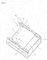
Fig. 1] Fig. 1 is a perspective view illustrating a component mounting station of a component mounting machine according to a first embodiment of the invention. - [
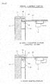
Fig. 2] Fig. 2(a) is a vertical cross-sectional view of a main part and illustrates a state in which a holding member is positioned at a normal clamping position and a lifting member is positioned at a board unclamping position (conveying position), andFig. 2(b) is a vertical cross--sectional view of the main part and illustrates a state in which the holding member is positioned at the normal clamping position and the lifting member is positioned at a board clamping position. -
[Fig. 3] Fig. 3(a) is a vertical cross-sectional view of the main part and illustrates a state in which the holding member is positioned at an upward warpage correction position and the lifting member is positioned at the board unclamping position (conveying positions), andFig. 3(b) is a vertical cross-sectional view of the main part and illustrates a state in which the holding member is positioned at the upward warpage correction position and the lifting member is positioned at the board clamping position. - [
Fig. 4] Fig. 4 is a vertical cross-sectional view of the main part for explaining an operation in which the upward warpage of the board is corrected. - [
Fig. 5] Fig. 5 (a) is a perspective view showing engagement between an engagement groove of the holding member and an engagement pin, andFig. 5(b) is a plain view of the same. - [
Fig. 6] Fig. 6 illustrates top views and vertical cross-sectional views showing states in which the position of the holding member is switched to (a) the upward warpage correction position, (b) the normal clamping position, and (c) a board removal position. - [
Fig. 7] Fig. 7 is a perspective view illustrating a component mounting station of a component mounting machine according to a second embodiment of the invention. - [
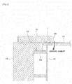
Fig. 8] Fig. 8(a) is a vertical cross-sectional view of the main part and illustrates a state of upward warpage correction according to a third embodiment of the invention, andFig. 8(b) is a vertical cross-sectional view of the main part and illustrates a state of normal clamping. - [
Fig. 9] Fig. 9(a) is a vertical cross-sectional view of the main part and illustrates a state of upward warpage correction according to a fourth embodiment of the invention, andFig. 9(b) is a vertical cross-sectional view of the main part and illustrates a state of normal clamping. - Hereinafter, descriptions will be given regarding four embodiments including first to fourth embodiments in which aspects of the invention are embodied.
- The first embodiment according to the invention will be described with reference to
Figs. 1 to 6 . First, a configuration of acomponent mounting station 11 of a component mounting machine is described with reference to Fag. 1. - The
component mounting station 11 is a place where a component is mounted on aboard 13, which is conveyed in an X direction by aconveyor 12, using a mounting head (not illustrated) of the component mounting machine. Theconveyor 12 includes twoconveyor belts 12a (seeFig. 2 ) on which left and right lateral end portions of theboard 13 are placed for transport. A width of the conveyor 12 (a distance between two conveyor belts 12) can be adjusted depending on a width of theboard 13 by moving aguide rail 14, which holds one of theconveyor belts 12a, in the width direction (Y direction) depending on the width of theboard 13. - A back-
up plate 16 on which a back-up pin 15 (back-up member) is disposed is horizontally disposed in thecomponent mounting station 11. The back-upplate 16 is made of a magnetic material such as iron, and configured to attract and hold the back-uppin 15 by means of a magnet (not illustrate) at an arbitrary position on the back-up plate 16 (where the back-uppin 15 does not interfere with thepre-mounted component 18 on the lower surface of theboard 13, for example) . The back-upplate 16 is moved up and down by alifting mechanism 17. A lowest position in moving-down operation corresponds to a board unclamping position illustrated inFig. 2 (a) and Fig. 3 (a) and a highest position in moving-up operation corresponds to a board clamping position illustrated inFig. 2 (b) and Fig. 3 (b) . - A plate-
like lifting member 21 is attached on each lateral end portion of the back-upplate 16 via asupport member 19 such that thelifting member 21 is positioned on each side in the width direction of the conveyor 12 (inner side of eachconveyor belt 12a) . A plate-like holding member 22 is attached on an upper end of eachguide rail 14 so as to protrude inwardly like a flange. - As illustrated in
Fig. 2(a) and Fig. 3(a) , in a state in which the back-upplate 16 is moved down to the board unclamping position, an upper end of the back-uppin 15 on the back-upplate 16 is positioned below a lower surface of theboard 13 on theconveyor 12, and the upper end of the back-uppin 15 on the back-upplate 16 is positioned below the lower end of a pre-mountedcomponent 18 on the lower surface of theboard 13 when thepre-mounted component 18 is mounted on the lower surface of theboard 13 on theconveyor 12. - Contrary to that, as illustrated in
Fig. 2(b) and Fig. 3(b) , in a state in which the back-upplate 16 is moved up to the board clamping position, the back-uppin 15 on the back-upplate 16 is moved up and the upper end of the back-uppin 15 comes in contact with the lower surface of theboard 13 on theconveyor 12 to support theboard 13 from below, whereby the downward warpage (downward curve) of theboard 13 is prevented. When the back-upplate 16 is moved up to the board clamping position, the liftingmember 21 moves up together with the back-upplate 16, and each of the left and right lateral end portions of theboard 13 is clamped between theholding member 22, which is attached to the upper end of theguide rail 14, and thelifting member 21. - As illustrated in
Fig. 4 , a slope surface 23 (upward warpage correction means) is formed on a part of the lower surface of the holdingmember 22 that overlaps with the lateral end portion of theboard 13 such that a distal end of theslope surface 23 protrudes downward. As illustrated inFig. 2 ,Fig. 3 , andFig. 6 , the holdingmember 22 is attached to be movable among the upward warpage correction position, the normal clamping position and the board removal position with respect to theguide rail 14 . As illustrated inFigs. 3 and4 , at the upward warpage correction position, the distal end portion of theslope surface 23, which is the lowest part of theslope surface 23 of the holdingmember 22, is positioned at an inner side of theboard 13 than the upper end of the liftingmember 21. While such a positional relationship is maintained, the lateral end portion of theboard 13 is nipped between the distal end portion of theslope surface 23 and the upper end of the liftingmember 21 to clamp theboard 13 in a state that downward bending moment is applied to theboard 13. - On the other hand, as illustrated in
Fig. 2 , at the normal clamping position, the distal end portion of theslope surface 23 of the holdingmember 22 is positioned directly above the upper end of the liftingmember 21, and there is no positional offset therebetween. While such a positional relationship is maintained, the lateral end portion of theboard 13 is nipped between the distal end portion of theslope surface 23 and the upper end of the liftingmember 21 to clamp theboard 13 in a state that the downward bending moment is not applied to theboard 13. - As illustrated in
Fig. 6(c) , the board removal position is a position where the holdingmember 22 is moved in a direction toward an outer side of theboard 13 and theboard 13 is removed upwardly in case of trouble or the like. - As illustrated in
Figs. 5 and6 , in order to hold and engage the holdingmember 22 at the upward warpage correction position, the normal clamping position, or the board removal position, the holdingmember 22 has anengagement groove 24 such as a labyrinth groove that hasengagement points member 22 can be switched among the upward warpage correction position, the normal clamping position and the board removal position by switching thepoints engagement groove 24 to be engaged with anengagement pin 25 fixed on the upper end of theguide rail 14. InFig. 5 , twoengagement grooves 24 are illustrated, but theengagement pin 25 is not illustrated in one of theengagement grooves 24. - In the first embodiment, as illustrated in
Figs. 5(a), (b ), the upper surface of theguide rail 14 has a position indication mark 26 (position indicator) for determining the position of the holdingmember 22 by image processing. Theposition indication mark 26 is configured such that theposition indication mark 26 is aligned with and exposed in one of three through-holes 20a to 20c formed on the holdingmember 22 when the position of the holdingmember 22 is switched among the upward warpage correction position, the normal clamping position and the board removal position. Then, a camera (camera that takes an image of a fiducial mark of the board 13) of the component mounting machine takes an image of an area including the three through-holes 20a to 20c of the holdingmember 22, and the image is processed by an image processing device (not illustrated) of the component mounting machine to recognize the position of the through-hole through which theposition indication mark 26 is exposed among the three through-holes 20a to 20c, whereby the position of the holdingmember 22 is determined. This allows confirmation whether the holdingmember 22 is moved to the correct position or not at the time of the production in advance. In this case, the presence of inclination of the holdingmember 22 can be determined when the position indication marks 26 are formed on the upper surface of theguide rail 14 in two or more positions along a longitudinal direction (X direction) thereof and sets of the three through-holes 20a to 20c are formed on the holdingmember 22 in two or more positions along the longitudinal direction (X direction) thereof, and the positions of the through-holes through which the position indication marks 26 are exposed are recognized at two or more positions by image recognition. - Alternatively, a plurality of the position indication marks (position indicator) may be formed on the upper surface of the holding
member 22, an image of the position indication marks may be taken by the camera of the component mounting machine, and then the image may be processed to determine the position or the presence of inclination of the holdingmember 22. - Alternatively, the
engagement groove 24 of the holdingmember 22 may be used as the position indicator, an image of theengagement groove 24 may be taken by the camera, and then the image may be processed to recognize the engagement position of theengagement pin 25 with respect to theengagement groove 24 and determine the position of the holdingmember 22. - Alternatively, the position indication marks may be provided on the upper surface of the
guide rail 14 at positions corresponding to the upward warping correction position, the normal clamping position and the board removal position such that the position indication marks are shifted from one another in the X direction (board conveying direction), the holdingmember 22 may have a slit extending in the X direction through which each of the position indication marks corresponding to the upward warpage correction position, the normal clamping position and the board removal position is exposed when the holdingmember 22 is positioned at each of the positions, the image of the slit of the holdingmember 22 may be taken by the camera, and then the image may be processed to recognize the position of the position indication mark in the slit to determine the position of the holdingmember 22. - When the upward warpage of the
board 13 is corrected by clamping theboard 13 using the board clamping apparatus having the above-described configuration, an operator moves the holdingmember 22 to the upward warpage correction position as illustrated inFig. 3, Fig. 4, and Fig. 6(a) such that the distal end portion of theslope surface 23 of the holdingmember 22 protrudes toward the inner side of theboard 13 than the upper end of the liftingmember 21. In this state, theboard 13 is placed on theconveyor 12, and then theboard 13 is conveyed to a predetermined operation position. Subsequently, the back-upplate 16 is moved up to the board clamping position and the liftingmember 21 is moved up together with the back-upplate 16 so that each of the left and right lateral end portions of theboard 13 is clamped between the holdingmember 22, which is attached to the upper end of theguide rail 14, and the liftingmember 21. - At the upward warpage correction position, since the distal end portion of the
slope surface 23 of the holdingmember 22 is positioned at the inner side of theboard 13 than the upper end of the liftingmember 21, the downward bending moment is applied to theboard 13 when the lateral end portion of theboard 13 is nipped between the distal end portion of theslope surface 23 of the holdingmember 22 and the upper end of the liftingmember 21, thereby the upward warpage of theboard 13 is corrected by the downward bending moment. At this time, theboard 13 to which the downward bending moment is applied is supported by the upper end of the back-uppin 15 from below, and thus the downward warpage of theboard 13 is also prevented. - When the
board 13 that does not require correction is clamped, as illustrated inFig. 2 and Fig. 6(b) , an operator moves the holdingmember 22 to the normal clamping position such that the distal end portion of theslope surface 23 of the holdingmember 22 is positioned directly above the upper end of the liftingmember 21 where there is no position offset therebetween. In such a sate, theboard 13 is placed on theconveyor 12, and then theboard 13 is conveyed to a predetermined operation position. Subsequently, the back-upplate 16 is moved up to the board clamping position and the liftingmember 21 is moved up together with the back-upplate 16 so that each of the left and right lateral end portions of theboard 13 is clamped between the holdingmember 22, which is attached to the upper end of theguide rail 14 , and the liftingmember 21. - At the normal clamping position, since the distal end portion of the
slope surface 23 of the holdingmember 22 is positioned directly above the upper end of the liftingmember 21 and there is no position offset therebetween, theboard 13 is clamped in a state that no downward bending moment is applied to theboard 13 when the lateral end portion of theboard 13 is nipped between the distal end portion of theslope surface 23 of the holdingmember 22 and the upper end of the liftingmember 21. At this time, theboard 13 is supported from below by the upper end of the back-uppin 15, and thus the downward warpage (downward curve) of theboard 13 is prevented. - When the holding
member 22 is to be removed upwardly in case of trouble or the like, as illustrated inFig. 6(c) , an operator moves the holdingmember 22 to the board removal position such that the holdingmember 22 is positioned at a position outside theboard 13 so as not to overlap with theboard 13. Then, theboard 13 on theconveyor 12 is removed upwardly. - According to the above-described first embodiment, the lateral end portion of the
board 13 is clamped between the liftingmember 21 and the holdingmember 22 so as to apply the downward bending moment to theboard 13 . Due to the downward bending moment, the upward warpage of theboard 13 is reliably corrected. In addition, even when the upward warpage of the double-sided mounting board is corrected, the upward warpage correction means (slope surface 23) does not interfere with thepre-mounted component 18 on the lower side of theboard 13 , and the upward warpage of theboard 13 is reliably corrected. Furthermore, the downward bending moment can be applied to theboard 13 by clamping action of nipping the lateral end portion of theboard 13 between the liftingmember 21 and the holdingmember 22, and thus the configuration for correction of the upward warpage of theboard 13 is simplified, which reduces the costs. - Furthermore, in the first embodiment, the downward bending moment can be applied to the
board 13 by a simple configuration in which theslope surface 23 as the upward warpage correction means is formed at the lower surface of the holdingmember 22, and the distal end portion of theslope surface 23, which is the lowest portion of theslope surface 23, is shifted from the upper end of the liftingmember 21, and therefore the costs can be minimized. - In such a case, if the downward bending moment applied to the
board 13 is too large, theboard 13 is warped downwardly beyond a flat state. However, in the first embodiment, theboard 13 to which the downward bending moment is applied is supported from below by the back-uppin 15, and thus the back-uppin 15 reliably prevents theboard 13 from being warped downwardly beyond a flat state by the downward bending moment applied to theboard 13. - In the first embodiment, the
slope surface 23 as the upward warpage correction means is formed at the lower surface of the holdingmember 22. However, instead of this, a distal end portion of the lower surface of the holdingmember 22 may be a projection protruding downwardly. Even with such a configuration, downward bending moment can be applied to theboard 13 when the lateral end portion of theboard 13 is clamped between the lowest portion on the distal end side of the lower surface of the holdingmember 22 and the upper end of the liftingmember 21. - In the above-described first embodiment, one holding
member 22 holds the entire area of the lateral end portion of theboard 13. However, in the second embodiment of the invention illustrated inFig. 7 , a plurality ofseparate holding members 22 are disposed along the lateral end portion of theboard 13, and each of the holdingmembers 22 is attached to be movable among the upward warpage correction position, the normal clamping position and the board removal position individually. Each of the holdingmembers 22 is movably attached to the upper end of theguide rail 14 by engagement between theengagement pin 25 fixed on the upper end of theguide rail 14 and theengagement groove 24. The other configurations are substantially the same as those of the above-described first embodiment. - In the above-described second embodiment, among the plurality of holding
members 22 positioned along the lateral end portion of theboard 13, only the holdingmember 22 positioned corresponding to an empty space in the lateral end portion of theboard 13 is moved to the upward warpage correction position for the upward warpage correction of theboard 13 . This minimizes dead space made by the holdingmember 22. - In the above-described first and second embodiments, the holding
member 22 is attached to the upper end of theguide rail 14 to be movable among the upward warpage correction position, the normal clamping position and the board removal position. However, in the third embodiment of the invention illustrated inFig. 8 , the holdingmember 22 for the upward warpage correction, which clamps theboard 13 in the state that the downward bending moment is applied to theboard 13 in the same configuration as that of the first embodiment, and a holdingmember 31 for the normal clamping, which clamps theboard 13 in the state that the downward bending moment is not applied to theboard 13, are replaceably attached to the upper end of theguide rail 14 by an engagement means, a screw or the like. The holdingmember 31 for the normal clamping does not require the slope surface at its lower surface. The holdingmember 31 for the normal clamping is attached such that the distal end portion thereof is positioned directly above the upper end of the liftingmember 21. The other configurations are substantially the same as those of the first embodiment. - The above-described third embodiment can also attain substantially the same effect as that of the first embodiment.
- In the fourth embodiment of the invention illustrated in
Fig. 9 , the downward bending moment is applied to theboard 13 by detachably attaching anattachment 32 for upward warpage correction, which functions as the upward warpage correction means, to the holdingmember 31 for the normal clamping, which clamps theboard 13 in the state that the downward bending moment is not applied to theboard 13, by a screw, an engagement means or the like. - The holding
member 31 for the normal clamping is attached to the upper end of theguide rail 14 by an engagement means, a screw or the like, as in the third embodiment. The holdingmember 31 for the normal clamping includes astep 33 at the upper surface thereof for positioning and attaching theattachment 32 for the upward warpage correction. Theattachment 32 for the upward warpage correction is detachably attached to thestep 33 by a screw, an engagement means or the like. In this configuration, the holdingmember 31 for the normal clamping to whichattachment 32 for the upward warpage correction is attached functions as the "holding member for the upward warpage correction". - As illustrated in
Fig. 9(a) , in a state where theattachment 32 for the upward warpage correction is attached to the holdingmember 31 for the normal clamping, thelowest portion 32a of the distal end portion of theattachment 32 is positioned below the lower surface of the holdingmember 31, and thelowest portion 32a of the distal end portion of theattachment 32 is positioned at the inner side of theboard 13 than the upper end of the liftingmember 21. While such a positional relationship is maintained, when the lateral end portion of theboard 13 is nipped between thelowest portion 32a of the distal end portion of theattachment 32 and the upper end of the liftingmember 21, theboard 13 is clamped in the state that the downward bending moment is applied to theboard 13. - On the other hand, as illustrated in
Fig. 9(b) , in a state in which theattachment 32 for the upward warpage correction is detached from the holdingmember 31 for the normal clamping, the distal end portion of the holdingmember 31 is positioned directly above the upper end of the liftingmember 21. When the lateral end portion of theboard 13 is nipped between the distal end portion of the holdingmember 31 and the upper end of the liftingmember 21, theboard 13 is clamped in the state that the downward bending moment is not applied to theboard 13. The other configurations are substantially the same as those of the first embodiment. - The above-described fourth embodiment can also attain substantially the same effect as that of the first embodiment. The invention is not limited to the board clamping apparatus of the component mounting machine and, as a matter of course, the invention can be implemented by being modified variously within a scope not departing from the gist of the invention, for example, the invention may be applied to a board clamping apparatus of a screen printer or any other various apparatus that conveys a board by a conveyor and clamps the board at a predetermined operation position.
- 11 ... COMPONENT MOUNTING STATION, 12 ... CONVEYOR, 12a ... CONVEYOR BELT, 13 ... BOARD, 14 ... GUIDE RAIL, 15 ... BACK-UP PIN (BACK-UP MEMBER), 16 ... BACK-UP PLATE, 17 ... LIFTING MECHANISM, 18 ... PRE-MOUNTED COMPONENT, 21 ... LIFTING MEMBER, 22 ... HOLDING MEMBER, 23 ... SLOPE SURFACE (UPWARD WARPAGE CORRECTION MEANS), 24 ... ENGAGEMENT GROOVE, 25 ... ENGAGEMENT PIN, 26: POSITION INDICATION MARK (POSITION INDICATOR), 31 ... HOLDING MEMBER FOR NORMAL CLAMPING, 32 ... ATTACHMENT FOR UPWARD WARPAGE CORRECTION
Claims (7)
- A board clamping apparatus in which a board conveyed by a conveyor is lifted by a lifting member from below at each side in a width direction of the board such that a lateral end portion of the board is clamped between the lifting member and a holding member positioned above the lifting member,
the board clamping apparatus comprising an upward warpage correction means for correcting upward warpage of the board by applying downward bending moment to the board by clamping the lateral end portion of the board between the lifting member and the holding member. - The board clamping apparatus according to Claim 1, wherein the holding member is attached to be movable between an upward warpage correction position and a normal clamping position with respect to each of guide rails positioned on both sides in a width direction of the conveyor, and the holding member is configured to clamp the board in a state that the downward bending moment is applied to the board by the upward warpage correction means at the upward warpage correction position and clamp the board in a state that the downward bending moment is not applied to the board at the normal clamping position.
- The board clamping apparatus according to Claim 2, wherein the apparatus includes: a position indicator for recognizing a position of the holding member; a camera that takes an image of the position indicator; and an image processing device that processes the image taken by the camera to recognize the position indicator and determine the position of the holding member.
- The board clamping apparatus according to Claim 2 or 3, wherein the holding member includes a plurality of separate holding members disposed along the lateral end portion of the board, and each of the plurality of separate holding members is attached to be movable between the upward warpage correction position and the normal clamping position individually.
- The board clamping apparatus according to Claim 1, wherein a holding member for upward warpage correction that clamps the board in a state that the downward bending moment is applied to the board by the upward warpage correction means is replaceable with a holding member for normal clamping that clamps the board in a state that the downward bending moment is not applied to the board.
- The board clamping apparatus according to Claim 1, wherein the board clamping apparatus is configured to apply the downward bending moment to the board by detachably attaching an attachment for upward warpage correction that functions as the upward warpage correction means to a holding member for normal clamping that clamps the board in a state that the downward bending moment is not applied to the board.
- The board clamping apparatus according to any one of Claims 1 to 6, wherein the upward warpage correction means is configured such that a portion of a lower surface of the holding member that overlaps with the lateral end portion of the board is formed in a slope shape or a protrusion shape in which a distal end of the portion protrudes downwardly and, in a state that a lowest portion in the slope shape or the protrusion shape is positioned at an inner side of the board than the upper end of the lifting member, the lateral end portion of the board is nipped between the lowest portion and the upper end of the lifting member so that the downward bending moment is applied to the board.
Applications Claiming Priority (1)
| Application Number | Priority Date | Filing Date | Title |
|---|---|---|---|
| PCT/JP2013/061527 WO2014170993A1 (en) | 2013-04-18 | 2013-04-18 | Substrate-clamp device |
Publications (3)
| Publication Number | Publication Date |
|---|---|
| EP2988582A1 true EP2988582A1 (en) | 2016-02-24 |
| EP2988582A4 EP2988582A4 (en) | 2016-05-04 |
| EP2988582B1 EP2988582B1 (en) | 2019-09-18 |
Family
ID=51730963
Family Applications (1)
| Application Number | Title | Priority Date | Filing Date |
|---|---|---|---|
| EP13882423.0A Active EP2988582B1 (en) | 2013-04-18 | 2013-04-18 | Substrate-clamp device |
Country Status (4)
| Country | Link |
|---|---|
| EP (1) | EP2988582B1 (en) |
| JP (1) | JP6086628B2 (en) |
| CN (1) | CN105122962B (en) |
| WO (1) | WO2014170993A1 (en) |
Cited By (2)
| Publication number | Priority date | Publication date | Assignee | Title |
|---|---|---|---|---|
| GB2568243A (en) * | 2017-11-07 | 2019-05-15 | Asm Assembly Systems Singapore Pte Ltd | Planarity alignment of stencils and workpieces |
| WO2021134103A1 (en) * | 2019-12-22 | 2021-07-01 | Bright Machines, Inc. | Configurable belt conveyor |
Families Citing this family (6)
| Publication number | Priority date | Publication date | Assignee | Title |
|---|---|---|---|---|
| WO2016203561A1 (en) * | 2015-06-17 | 2016-12-22 | 富士機械製造株式会社 | Substrate holding device |
| JP6622500B2 (en) * | 2015-07-29 | 2019-12-18 | 株式会社Fuji | Transport device |
| EP3644700B1 (en) * | 2017-06-20 | 2022-08-24 | Fuji Corporation | Electronic component mounting machine |
| CN107864605B (en) * | 2017-12-21 | 2024-04-05 | 立昱电子(惠州)有限公司 | Correcting device for preventing product from falling and shifting of anti-sticking machine |
| JP6994626B2 (en) * | 2018-02-14 | 2022-01-14 | パナソニックIpマネジメント株式会社 | Board holding device and component mounting device |
| CN109250486B (en) * | 2018-10-18 | 2024-03-26 | 李荣根 | Quick plate taking and placing device, plate taking and placing equipment and plate taking and placing method |
Family Cites Families (10)
| Publication number | Priority date | Publication date | Assignee | Title |
|---|---|---|---|---|
| JPS6127277U (en) * | 1984-07-20 | 1986-02-18 | 一光 牧野 | Printed circuit board warp correction device |
| JP2792931B2 (en) | 1989-08-25 | 1998-09-03 | 三洋電機株式会社 | Electronic component mounting device |
| JPH083035Y2 (en) * | 1989-12-26 | 1996-01-29 | 三洋電機株式会社 | Substrate support device |
| JPH0563400A (en) * | 1991-09-05 | 1993-03-12 | Sony Corp | Substrate warp correction device |
| JPH10501926A (en) * | 1995-03-28 | 1998-02-17 | フィリップス エレクトロニクス ネムローゼ フェンノートシャップ | Method of positioning a printed wiring board in a component placement machine and component placement machine for this method |
| JP3752042B2 (en) * | 1997-02-20 | 2006-03-08 | 山形カシオ株式会社 | Substrate positioning device |
| US6631557B2 (en) | 2000-01-31 | 2003-10-14 | Shibaura Mechatronics Corporation | Method and apparatus for mounting electronic device |
| JP4701567B2 (en) * | 2001-09-13 | 2011-06-15 | ソニー株式会社 | Component mounting method and apparatus |
| JP2004335973A (en) | 2003-05-12 | 2004-11-25 | Matsushita Electric Ind Co Ltd | Substrate support jig |
| JP5652700B2 (en) * | 2010-02-09 | 2015-01-14 | 富士電機株式会社 | Position control device for flexible substrate |
-
2013
- 2013-04-18 WO PCT/JP2013/061527 patent/WO2014170993A1/en not_active Ceased
- 2013-04-18 CN CN201380075636.6A patent/CN105122962B/en active Active
- 2013-04-18 EP EP13882423.0A patent/EP2988582B1/en active Active
- 2013-04-18 JP JP2015512253A patent/JP6086628B2/en active Active
Cited By (6)
| Publication number | Priority date | Publication date | Assignee | Title |
|---|---|---|---|---|
| GB2568243A (en) * | 2017-11-07 | 2019-05-15 | Asm Assembly Systems Singapore Pte Ltd | Planarity alignment of stencils and workpieces |
| US10994527B2 (en) | 2017-11-07 | 2021-05-04 | Asm Assembly Systems Singapore Pte. Ltd. | Planarity alignment of stencils and workpieces |
| WO2021134103A1 (en) * | 2019-12-22 | 2021-07-01 | Bright Machines, Inc. | Configurable belt conveyor |
| US11345550B2 (en) * | 2019-12-22 | 2022-05-31 | Bright Machines, Inc. | Configurable belt conveyor |
| IL271653B1 (en) * | 2019-12-22 | 2024-06-01 | Bright Machines Ltd | Configurable Belt Conveyor |
| IL271653B2 (en) * | 2019-12-22 | 2024-10-01 | Bright Machines Ltd | Adjustable conveyor belt |
Also Published As
| Publication number | Publication date |
|---|---|
| CN105122962B (en) | 2018-04-06 |
| EP2988582B1 (en) | 2019-09-18 |
| EP2988582A4 (en) | 2016-05-04 |
| JPWO2014170993A1 (en) | 2017-02-16 |
| CN105122962A (en) | 2015-12-02 |
| JP6086628B2 (en) | 2017-03-01 |
| WO2014170993A1 (en) | 2014-10-23 |
Similar Documents
| Publication | Publication Date | Title |
|---|---|---|
| EP2988582B1 (en) | Substrate-clamp device | |
| US10462948B2 (en) | Mounting deviation correction apparatus and component mounting system | |
| KR20090064306A (en) | Screen printing machine | |
| US9393776B2 (en) | Screen printing apparatus | |
| CN106413372B (en) | Conveying device | |
| JP6857241B2 (en) | Electronic component mounting machine | |
| JP2005205646A (en) | Screen printing device | |
| JP6556611B2 (en) | Component mounter | |
| JP5495260B2 (en) | Parts mounting machine | |
| WO2018216132A1 (en) | Measurement position determination device | |
| US10856458B2 (en) | Substrate transfer device | |
| JP4237158B2 (en) | Mounting board manufacturing apparatus and manufacturing method | |
| JP2013201204A (en) | Component mounting device and component mounting method | |
| CN107006145B (en) | Substrate work machine | |
| JP6086435B2 (en) | PCB clamp device | |
| JP4946364B2 (en) | SCREEN PRINTING APPARATUS AND SUBJECT EXCHANGE METHOD FOR SCREEN PRINTING APPARATUS | |
| KR101656815B1 (en) | PCB separation device for screen printer | |
| JP6861335B2 (en) | Component mounting device and component mounting method | |
| JP2010046843A (en) | Screen printing machine | |
| JP4851314B2 (en) | Printed circuit board holding device | |
| JP5214516B2 (en) | Support pin transfer device | |
| JP4337622B2 (en) | Substrate underlay device | |
| JP2014082232A (en) | Fixing structure of planar body and substrate support device using the same | |
| JP2006142763A (en) | Screen printing machine | |
| JPWO2017009967A1 (en) | Anti-substrate working machine and anti-substrate working system |
Legal Events
| Date | Code | Title | Description |
|---|---|---|---|
| PUAI | Public reference made under article 153(3) epc to a published international application that has entered the european phase |
Free format text: ORIGINAL CODE: 0009012 |
|
| 17P | Request for examination filed |
Effective date: 20151016 |
|
| AK | Designated contracting states |
Kind code of ref document: A1 Designated state(s): AL AT BE BG CH CY CZ DE DK EE ES FI FR GB GR HR HU IE IS IT LI LT LU LV MC MK MT NL NO PL PT RO RS SE SI SK SM TR |
|
| AX | Request for extension of the european patent |
Extension state: BA ME |
|
| A4 | Supplementary search report drawn up and despatched |
Effective date: 20160405 |
|
| RIC1 | Information provided on ipc code assigned before grant |
Ipc: H05K 13/04 20060101AFI20160330BHEP Ipc: H05K 3/34 20060101ALI20160330BHEP |
|
| DAX | Request for extension of the european patent (deleted) | ||
| RAP1 | Party data changed (applicant data changed or rights of an application transferred) |
Owner name: FUJI CORPORATION |
|
| RIN1 | Information on inventor provided before grant (corrected) |
Inventor name: TANAKA, KEITA Inventor name: MIZUNO, TAKAYUKI Inventor name: KAWAI, HIDETOSHI Inventor name: ITO, HIDETOSHI |
|
| REG | Reference to a national code |
Ref country code: DE Ref legal event code: R079 Ref document number: 602013060824 Country of ref document: DE Free format text: PREVIOUS MAIN CLASS: H05K0013040000 Ipc: H05K0013000000 |
|
| GRAP | Despatch of communication of intention to grant a patent |
Free format text: ORIGINAL CODE: EPIDOSNIGR1 |
|
| STAA | Information on the status of an ep patent application or granted ep patent |
Free format text: STATUS: GRANT OF PATENT IS INTENDED |
|
| RIC1 | Information provided on ipc code assigned before grant |
Ipc: H05K 13/00 20060101AFI20190507BHEP Ipc: H05K 3/12 20060101ALI20190507BHEP |
|
| INTG | Intention to grant announced |
Effective date: 20190529 |
|
| GRAS | Grant fee paid |
Free format text: ORIGINAL CODE: EPIDOSNIGR3 |
|
| GRAA | (expected) grant |
Free format text: ORIGINAL CODE: 0009210 |
|
| STAA | Information on the status of an ep patent application or granted ep patent |
Free format text: STATUS: THE PATENT HAS BEEN GRANTED |
|
| AK | Designated contracting states |
Kind code of ref document: B1 Designated state(s): AL AT BE BG CH CY CZ DE DK EE ES FI FR GB GR HR HU IE IS IT LI LT LU LV MC MK MT NL NO PL PT RO RS SE SI SK SM TR |
|
| REG | Reference to a national code |
Ref country code: GB Ref legal event code: FG4D |
|
| REG | Reference to a national code |
Ref country code: CH Ref legal event code: EP |
|
| REG | Reference to a national code |
Ref country code: DE Ref legal event code: R096 Ref document number: 602013060824 Country of ref document: DE |
|
| REG | Reference to a national code |
Ref country code: AT Ref legal event code: REF Ref document number: 1182871 Country of ref document: AT Kind code of ref document: T Effective date: 20191015 |
|
| REG | Reference to a national code |
Ref country code: IE Ref legal event code: FG4D |
|
| REG | Reference to a national code |
Ref country code: NL Ref legal event code: FP |
|
| PG25 | Lapsed in a contracting state [announced via postgrant information from national office to epo] |
Ref country code: HR Free format text: LAPSE BECAUSE OF FAILURE TO SUBMIT A TRANSLATION OF THE DESCRIPTION OR TO PAY THE FEE WITHIN THE PRESCRIBED TIME-LIMIT Effective date: 20190918 Ref country code: LT Free format text: LAPSE BECAUSE OF FAILURE TO SUBMIT A TRANSLATION OF THE DESCRIPTION OR TO PAY THE FEE WITHIN THE PRESCRIBED TIME-LIMIT Effective date: 20190918 Ref country code: NO Free format text: LAPSE BECAUSE OF FAILURE TO SUBMIT A TRANSLATION OF THE DESCRIPTION OR TO PAY THE FEE WITHIN THE PRESCRIBED TIME-LIMIT Effective date: 20191218 Ref country code: FI Free format text: LAPSE BECAUSE OF FAILURE TO SUBMIT A TRANSLATION OF THE DESCRIPTION OR TO PAY THE FEE WITHIN THE PRESCRIBED TIME-LIMIT Effective date: 20190918 Ref country code: SE Free format text: LAPSE BECAUSE OF FAILURE TO SUBMIT A TRANSLATION OF THE DESCRIPTION OR TO PAY THE FEE WITHIN THE PRESCRIBED TIME-LIMIT Effective date: 20190918 Ref country code: BG Free format text: LAPSE BECAUSE OF FAILURE TO SUBMIT A TRANSLATION OF THE DESCRIPTION OR TO PAY THE FEE WITHIN THE PRESCRIBED TIME-LIMIT Effective date: 20191218 |
|
| REG | Reference to a national code |
Ref country code: LT Ref legal event code: MG4D |
|
| PG25 | Lapsed in a contracting state [announced via postgrant information from national office to epo] |
Ref country code: RS Free format text: LAPSE BECAUSE OF FAILURE TO SUBMIT A TRANSLATION OF THE DESCRIPTION OR TO PAY THE FEE WITHIN THE PRESCRIBED TIME-LIMIT Effective date: 20190918 Ref country code: LV Free format text: LAPSE BECAUSE OF FAILURE TO SUBMIT A TRANSLATION OF THE DESCRIPTION OR TO PAY THE FEE WITHIN THE PRESCRIBED TIME-LIMIT Effective date: 20190918 Ref country code: AL Free format text: LAPSE BECAUSE OF FAILURE TO SUBMIT A TRANSLATION OF THE DESCRIPTION OR TO PAY THE FEE WITHIN THE PRESCRIBED TIME-LIMIT Effective date: 20190918 Ref country code: GR Free format text: LAPSE BECAUSE OF FAILURE TO SUBMIT A TRANSLATION OF THE DESCRIPTION OR TO PAY THE FEE WITHIN THE PRESCRIBED TIME-LIMIT Effective date: 20191219 |
|
| REG | Reference to a national code |
Ref country code: AT Ref legal event code: MK05 Ref document number: 1182871 Country of ref document: AT Kind code of ref document: T Effective date: 20190918 |
|
| PG25 | Lapsed in a contracting state [announced via postgrant information from national office to epo] |
Ref country code: AT Free format text: LAPSE BECAUSE OF FAILURE TO SUBMIT A TRANSLATION OF THE DESCRIPTION OR TO PAY THE FEE WITHIN THE PRESCRIBED TIME-LIMIT Effective date: 20190918 Ref country code: PL Free format text: LAPSE BECAUSE OF FAILURE TO SUBMIT A TRANSLATION OF THE DESCRIPTION OR TO PAY THE FEE WITHIN THE PRESCRIBED TIME-LIMIT Effective date: 20190918 Ref country code: ES Free format text: LAPSE BECAUSE OF FAILURE TO SUBMIT A TRANSLATION OF THE DESCRIPTION OR TO PAY THE FEE WITHIN THE PRESCRIBED TIME-LIMIT Effective date: 20190918 Ref country code: RO Free format text: LAPSE BECAUSE OF FAILURE TO SUBMIT A TRANSLATION OF THE DESCRIPTION OR TO PAY THE FEE WITHIN THE PRESCRIBED TIME-LIMIT Effective date: 20190918 Ref country code: EE Free format text: LAPSE BECAUSE OF FAILURE TO SUBMIT A TRANSLATION OF THE DESCRIPTION OR TO PAY THE FEE WITHIN THE PRESCRIBED TIME-LIMIT Effective date: 20190918 Ref country code: PT Free format text: LAPSE BECAUSE OF FAILURE TO SUBMIT A TRANSLATION OF THE DESCRIPTION OR TO PAY THE FEE WITHIN THE PRESCRIBED TIME-LIMIT Effective date: 20200120 |
|
| PG25 | Lapsed in a contracting state [announced via postgrant information from national office to epo] |
Ref country code: IS Free format text: LAPSE BECAUSE OF FAILURE TO SUBMIT A TRANSLATION OF THE DESCRIPTION OR TO PAY THE FEE WITHIN THE PRESCRIBED TIME-LIMIT Effective date: 20200224 Ref country code: SM Free format text: LAPSE BECAUSE OF FAILURE TO SUBMIT A TRANSLATION OF THE DESCRIPTION OR TO PAY THE FEE WITHIN THE PRESCRIBED TIME-LIMIT Effective date: 20190918 Ref country code: CZ Free format text: LAPSE BECAUSE OF FAILURE TO SUBMIT A TRANSLATION OF THE DESCRIPTION OR TO PAY THE FEE WITHIN THE PRESCRIBED TIME-LIMIT Effective date: 20190918 Ref country code: SK Free format text: LAPSE BECAUSE OF FAILURE TO SUBMIT A TRANSLATION OF THE DESCRIPTION OR TO PAY THE FEE WITHIN THE PRESCRIBED TIME-LIMIT Effective date: 20190918 |
|
| REG | Reference to a national code |
Ref country code: DE Ref legal event code: R097 Ref document number: 602013060824 Country of ref document: DE |
|
| PLBE | No opposition filed within time limit |
Free format text: ORIGINAL CODE: 0009261 |
|
| STAA | Information on the status of an ep patent application or granted ep patent |
Free format text: STATUS: NO OPPOSITION FILED WITHIN TIME LIMIT |
|
| PG2D | Information on lapse in contracting state deleted |
Ref country code: IS |
|
| PG25 | Lapsed in a contracting state [announced via postgrant information from national office to epo] |
Ref country code: DK Free format text: LAPSE BECAUSE OF FAILURE TO SUBMIT A TRANSLATION OF THE DESCRIPTION OR TO PAY THE FEE WITHIN THE PRESCRIBED TIME-LIMIT Effective date: 20190918 Ref country code: IS Free format text: LAPSE BECAUSE OF FAILURE TO SUBMIT A TRANSLATION OF THE DESCRIPTION OR TO PAY THE FEE WITHIN THE PRESCRIBED TIME-LIMIT Effective date: 20200119 |
|
| 26N | No opposition filed |
Effective date: 20200619 |
|
| PG25 | Lapsed in a contracting state [announced via postgrant information from national office to epo] |
Ref country code: SI Free format text: LAPSE BECAUSE OF FAILURE TO SUBMIT A TRANSLATION OF THE DESCRIPTION OR TO PAY THE FEE WITHIN THE PRESCRIBED TIME-LIMIT Effective date: 20190918 |
|
| PG25 | Lapsed in a contracting state [announced via postgrant information from national office to epo] |
Ref country code: MC Free format text: LAPSE BECAUSE OF FAILURE TO SUBMIT A TRANSLATION OF THE DESCRIPTION OR TO PAY THE FEE WITHIN THE PRESCRIBED TIME-LIMIT Effective date: 20190918 |
|
| REG | Reference to a national code |
Ref country code: CH Ref legal event code: PL |
|
| PG25 | Lapsed in a contracting state [announced via postgrant information from national office to epo] |
Ref country code: LI Free format text: LAPSE BECAUSE OF NON-PAYMENT OF DUE FEES Effective date: 20200430 Ref country code: CH Free format text: LAPSE BECAUSE OF NON-PAYMENT OF DUE FEES Effective date: 20200430 Ref country code: LU Free format text: LAPSE BECAUSE OF NON-PAYMENT OF DUE FEES Effective date: 20200418 |
|
| REG | Reference to a national code |
Ref country code: BE Ref legal event code: MM Effective date: 20200430 |
|
| PG25 | Lapsed in a contracting state [announced via postgrant information from national office to epo] |
Ref country code: BE Free format text: LAPSE BECAUSE OF NON-PAYMENT OF DUE FEES Effective date: 20200430 |
|
| GBPC | Gb: european patent ceased through non-payment of renewal fee |
Effective date: 20200418 |
|
| PG25 | Lapsed in a contracting state [announced via postgrant information from national office to epo] |
Ref country code: GB Free format text: LAPSE BECAUSE OF NON-PAYMENT OF DUE FEES Effective date: 20200418 Ref country code: IE Free format text: LAPSE BECAUSE OF NON-PAYMENT OF DUE FEES Effective date: 20200418 |
|
| PG25 | Lapsed in a contracting state [announced via postgrant information from national office to epo] |
Ref country code: TR Free format text: LAPSE BECAUSE OF FAILURE TO SUBMIT A TRANSLATION OF THE DESCRIPTION OR TO PAY THE FEE WITHIN THE PRESCRIBED TIME-LIMIT Effective date: 20190918 Ref country code: MT Free format text: LAPSE BECAUSE OF FAILURE TO SUBMIT A TRANSLATION OF THE DESCRIPTION OR TO PAY THE FEE WITHIN THE PRESCRIBED TIME-LIMIT Effective date: 20190918 Ref country code: CY Free format text: LAPSE BECAUSE OF FAILURE TO SUBMIT A TRANSLATION OF THE DESCRIPTION OR TO PAY THE FEE WITHIN THE PRESCRIBED TIME-LIMIT Effective date: 20190918 |
|
| PG25 | Lapsed in a contracting state [announced via postgrant information from national office to epo] |
Ref country code: MK Free format text: LAPSE BECAUSE OF FAILURE TO SUBMIT A TRANSLATION OF THE DESCRIPTION OR TO PAY THE FEE WITHIN THE PRESCRIBED TIME-LIMIT Effective date: 20190918 |
|
| P01 | Opt-out of the competence of the unified patent court (upc) registered |
Effective date: 20230328 |
|
| PGFP | Annual fee paid to national office [announced via postgrant information from national office to epo] |
Ref country code: DE Payment date: 20250305 Year of fee payment: 13 |
|
| PGFP | Annual fee paid to national office [announced via postgrant information from national office to epo] |
Ref country code: IT Payment date: 20260320 Year of fee payment: 14 |
|
| PGFP | Annual fee paid to national office [announced via postgrant information from national office to epo] |
Ref country code: NL Payment date: 20260317 Year of fee payment: 14 |
|
| PGFP | Annual fee paid to national office [announced via postgrant information from national office to epo] |
Ref country code: FR Payment date: 20260309 Year of fee payment: 14 |