EP2988188A2 - Thermostat unit and method of automatically regulating the room temperature - Google Patents
Thermostat unit and method of automatically regulating the room temperature Download PDFInfo
- Publication number
- EP2988188A2 EP2988188A2 EP15173473.8A EP15173473A EP2988188A2 EP 2988188 A2 EP2988188 A2 EP 2988188A2 EP 15173473 A EP15173473 A EP 15173473A EP 2988188 A2 EP2988188 A2 EP 2988188A2
- Authority
- EP
- European Patent Office
- Prior art keywords
- thermostat unit
- temperature
- sensor
- mode
- room
- Prior art date
- Legal status (The legal status is an assumption and is not a legal conclusion. Google has not performed a legal analysis and makes no representation as to the accuracy of the status listed.)
- Granted
Links
- 238000000034 method Methods 0.000 title claims abstract description 37
- 230000001105 regulatory effect Effects 0.000 title description 2
- 238000001514 detection method Methods 0.000 claims abstract description 63
- 230000033001 locomotion Effects 0.000 claims abstract description 53
- 238000012545 processing Methods 0.000 claims abstract description 36
- 230000008859 change Effects 0.000 claims description 35
- 230000006870 function Effects 0.000 claims description 33
- 230000000694 effects Effects 0.000 claims description 29
- 238000012546 transfer Methods 0.000 claims description 7
- 238000000926 separation method Methods 0.000 claims description 5
- 230000035945 sensitivity Effects 0.000 claims description 3
- 230000036962 time dependent Effects 0.000 claims description 3
- 210000003813 thumb Anatomy 0.000 claims description 2
- 238000010438 heat treatment Methods 0.000 description 26
- 238000009434 installation Methods 0.000 description 10
- 230000001276 controlling effect Effects 0.000 description 9
- 230000002349 favourable effect Effects 0.000 description 6
- 241000288921 Desmodus Species 0.000 description 5
- 230000008901 benefit Effects 0.000 description 5
- 238000004891 communication Methods 0.000 description 4
- 230000001419 dependent effect Effects 0.000 description 4
- 230000009467 reduction Effects 0.000 description 4
- 230000006399 behavior Effects 0.000 description 3
- 238000009472 formulation Methods 0.000 description 3
- 238000005259 measurement Methods 0.000 description 3
- 239000000203 mixture Substances 0.000 description 3
- 230000008569 process Effects 0.000 description 3
- 230000009471 action Effects 0.000 description 2
- 230000009286 beneficial effect Effects 0.000 description 2
- 238000011161 development Methods 0.000 description 2
- 238000005265 energy consumption Methods 0.000 description 2
- 238000005516 engineering process Methods 0.000 description 2
- 230000010354 integration Effects 0.000 description 2
- 230000003993 interaction Effects 0.000 description 2
- 230000000670 limiting effect Effects 0.000 description 2
- 238000012544 monitoring process Methods 0.000 description 2
- 230000000717 retained effect Effects 0.000 description 2
- 241000282326 Felis catus Species 0.000 description 1
- 241001465754 Metazoa Species 0.000 description 1
- 230000004913 activation Effects 0.000 description 1
- 230000005540 biological transmission Effects 0.000 description 1
- 230000023077 detection of light stimulus Effects 0.000 description 1
- 230000004069 differentiation Effects 0.000 description 1
- 230000006872 improvement Effects 0.000 description 1
- 230000004048 modification Effects 0.000 description 1
- 238000012986 modification Methods 0.000 description 1
- 230000036961 partial effect Effects 0.000 description 1
- 230000002829 reductive effect Effects 0.000 description 1
- 230000007363 regulatory process Effects 0.000 description 1
- 238000009420 retrofitting Methods 0.000 description 1
- 230000002441 reversible effect Effects 0.000 description 1
- 230000035807 sensation Effects 0.000 description 1
- 208000019116 sleep disease Diseases 0.000 description 1
- 230000036578 sleeping time Effects 0.000 description 1
- 230000007704 transition Effects 0.000 description 1
- 230000001960 triggered effect Effects 0.000 description 1
- XLYOFNOQVPJJNP-UHFFFAOYSA-N water Substances O XLYOFNOQVPJJNP-UHFFFAOYSA-N 0.000 description 1
Images

Classifications
-
- G—PHYSICS
- G05—CONTROLLING; REGULATING
- G05D—SYSTEMS FOR CONTROLLING OR REGULATING NON-ELECTRIC VARIABLES
- G05D23/00—Control of temperature
- G05D23/19—Control of temperature characterised by the use of electric means
- G05D23/1902—Control of temperature characterised by the use of electric means characterised by the use of a variable reference value
-
- F—MECHANICAL ENGINEERING; LIGHTING; HEATING; WEAPONS; BLASTING
- F16—ENGINEERING ELEMENTS AND UNITS; GENERAL MEASURES FOR PRODUCING AND MAINTAINING EFFECTIVE FUNCTIONING OF MACHINES OR INSTALLATIONS; THERMAL INSULATION IN GENERAL
- F16K—VALVES; TAPS; COCKS; ACTUATING-FLOATS; DEVICES FOR VENTING OR AERATING
- F16K37/00—Special means in or on valves or other cut-off apparatus for indicating or recording operation thereof, or for enabling an alarm to be given
- F16K37/0025—Electrical or magnetic means
-
- F—MECHANICAL ENGINEERING; LIGHTING; HEATING; WEAPONS; BLASTING
- F24—HEATING; RANGES; VENTILATING
- F24D—DOMESTIC- OR SPACE-HEATING SYSTEMS, e.g. CENTRAL HEATING SYSTEMS; DOMESTIC HOT-WATER SUPPLY SYSTEMS; ELEMENTS OR COMPONENTS THEREFOR
- F24D19/00—Details
- F24D19/10—Arrangement or mounting of control or safety devices
- F24D19/1006—Arrangement or mounting of control or safety devices for water heating systems
- F24D19/1009—Arrangement or mounting of control or safety devices for water heating systems for central heating
- F24D19/1015—Arrangement or mounting of control or safety devices for water heating systems for central heating using a valve or valves
- F24D19/1018—Radiator valves
-
- F—MECHANICAL ENGINEERING; LIGHTING; HEATING; WEAPONS; BLASTING
- F24—HEATING; RANGES; VENTILATING
- F24D—DOMESTIC- OR SPACE-HEATING SYSTEMS, e.g. CENTRAL HEATING SYSTEMS; DOMESTIC HOT-WATER SUPPLY SYSTEMS; ELEMENTS OR COMPONENTS THEREFOR
- F24D2220/00—Components of central heating installations excluding heat sources
- F24D2220/02—Fluid distribution means
- F24D2220/0257—Thermostatic valves
Definitions
- the invention relates to a sensor-controlled thermostat unit. Furthermore, the invention relates to a method for automatically controlling the room temperature with the first described thermostat unit.
- On-demand automatic room temperature control is becoming increasingly important in times of high energy costs and CO 2 emission reduction goals.
- thermostats have been electronically controlled thermostats for many years available, which take the respective setpoints for temperature control of a clock and calendar function. For example, here times for a night reduction of the room temperature can be programmed, so that from a certain time the room temperature is reduced and the next morning is increased again from a certain time.
- a disadvantage of this type of time-controlled thermostats is that there is no flexibility against the changed habits of the people who use the room. For example, on a public holiday, which is otherwise a working day, normal temperature control would take place for one working day. The thermostat would not take into account that people are longer in the room and active in the evenings and sleep longer than usual in the morning.
- the motion sensors for such spatially distributed systems are usually attached to the ceilings of the rooms and detect movements seen from above down.
- movements and thus the presence of pets, such as cats are recorded in the same way as the presence of persons.
- the information on the presence of persons generated thereby leads to an increase in the room temperature. This is undesirable at this point because the comfortable room temperature for present people is not required for the mere presence of pets.
- the cause of the unintentional raising of the room temperature is that conventional motion sensors can not distinguish between humans and pets, which has a negative effect on the control behavior.
- a sensor-controlled thermostat unit for automatic and needs-based control of the room temperature, which can be installed or retrofitted with little effort.
- the thermostat unit is intended to detect the presence of persons in the room with a higher accuracy and distinguish it from the presence of pets.
- a method is proposed, which allows using the thermostat and its sensors, an intelligent control of the room temperature.
- a thermostat unit comprising arranged on or in a housing a temperature sensor, a temperature controller, at least one light sensor, a data processing unit, and at least one, at least two mutually different detection fields comprising motion sensor, wherein a Temperature control is provided based on at least one sensor signal.
- the invention comprises a thermostat unit having a temperature sensor for receiving the current room temperature.
- the values of this temperature sensor are continuously compared with the respective setpoint.
- the temperature controller which is also part of the invention, then optionally regulates the heating power if the current value deviates from the desired value.
- the thermostat unit has at least one light sensor.
- the values of this light sensor are used as input information to detect the presence or activity of persons in the room or the time of day.
- the input information is processed by a data processing unit into signals for controlling the temperature controller.
- the data processing unit is, for example, a programmable logic controller having input and output channels and a memory.
- the data processing unit can be programmed to set the desired control behavior of the thermostat unit.
- At least one motion sensor is provided which monitors at least two mutually different detection fields. These two different fields of coverage make it possible to distinguish persons present in the room from pets.
- the different detection fields could be set such that a detection field only detects low / small organisms, for example by setting the field to a detection range of up to 1 m above the floor of the room.
- the second detection field is then set to a range from 1 m above the floor of the room.
- Human activity is then detected by the computing device only if motion is detected in both detection fields becomes. If only movement in a detection field is detected, there is no presence of persons in the room.
- the thermostat unit performs a control of the room temperature based on at least one sensor signal.
- This at least one sensor signal may be a signal of a light sensor or of a motion sensor.
- the data processing unit comprises a time and calendar function and a memory.
- this memory In this memory then both setpoints for the temperature control as well as time and date values can be stored. This makes it possible to influence the temperature control via programmed appointments. For example, holiday periods can be stored in which other, lower setpoint temperatures are corrected. Also common times for the transitions between day and night or activity or non-activity of people in the room can be stored. Due to the clock and calendar function, it is then always possible for the thermostat unit to apply a setpoint stored in the memory for temperature control. Furthermore, all setpoints for temperature control can always be changed as needed.
- the thermostat unit has an input element, in particular a thumbwheel.
- This setting wheel can be used to manually set the temperature. If a person present in the room is not satisfied with the room temperature at hand, the room temperature can be changed manually without having to worry about programming the thermostat unit.
- the setting wheel it is possible by the setting wheel, the setpoints in the memory of the data processing unit modify and thus influence the control characteristics in automatic mode.
- the time and date values in the memory of the data processing unit can be changed user-friendly via the setting wheel. It is also possible to switch off the entire thermostat unit via the setting wheel. This could be realized for example via a switch in an end position of the setting wheel, without limiting the invention to this solution.
- thermostat unit can be easily switched off at any time even by persons who are unfamiliar with the details of the thermostat unit. Furthermore, it is possible to influence the sensitivity of at least one of the sensors via the setting wheel. This makes it possible, for example, for the light sensor to be adapted to the brightness conditions of its installation position.
- the invention is not limited to an adjusting wheel as an input element. It can also be used various other input elements such as lock slider, rotary switch or lever.
- the thermostat unit has at least one display and / or at least one key operating element.
- a display enables the display of the current setpoint and actual temperature. Furthermore, other useful information such as the type of applied operating mode or date and time can be displayed. Also, when programming the thermostat unit, the parameters can be shown on the display.
- the tasks of the display can also be realized by control lamps, LEDs or other display elements.
- One or more key controls ensure that different modes of temperature control can be selected directly by simply pressing a button.
- setpoints for the temperature or time and date values can be stored in the memory of the key presses Data processing unit to be entered. The inputs can also be via rocker arms, thermal sensors or a touchpad, as it is used for example in smartphones. Of course, the entries are also possible in combination with the setting wheel.
- At least one light sensor is provided on an upper side of the housing of the thermostat unit without limiting the invention thereto.
- the arrangement on top of the unit allows optimal detection of light, as both daylight and artificial light is emitted from above.
- the housing can thus not obscure the detection range of the light sensor.
- an automatic control of the thermostat unit is provided by the data processing unit based on the signals of at least one light sensor.
- the brightnesses detected by the light sensor are converted by the data processing unit into information that influences the presence of active persons in the room. For example, when registering higher brightness at night, it can be concluded that artificial light has been turned on. This in turn indicates the activity of people in the room and causes the temperature to rise.
- the signals of the at least one light sensor are combined with stored in the memory records of light and dark phases. It is possible to store in the memory of the thermostat unit records with the beginning and end of the daylight duration depending on date and season. By knowing at which times daylight is present, and thus brightness registered by the light sensor is not necessarily the cause of activity of Persons must be in the room, the accuracy for detecting active people in the room can be further improved.
- the thermostat unit can be attached directly to a radiator via a connection. It is thus ensured a very simple installation of the thermostat unit.
- the thermostat unit can be mounted in the same manner as an ordinary, manual rotary thermostat, for example via sliding sleeves, Unterschmuffen or the like. Special expertise is therefore not required when mounting the thermostat unit.
- the position and orientation of the thermostat unit and / or the least one sensor in the room relative to the connection to the radiator are / is adjustable.
- Advantage of this feature is that depending on the installation position on the radiator, the detection ranges of the sensors in the room can be individually and optimally aligned. This is important for high accuracy in detecting active people in the room.
- the position of one or both detection fields on the motion sensor is adjustable. This feature is used to optimize the accuracy of recognizing people in the room. An adjustability of the detection fields ensures an optimal separation between the recognition of persons and the recognition of, for example, domestic animals.
- the detection fields are separated by a parting plane and the detection areas each have a detection angle relative to the parting plane.
- the parting plane in this embodiment excludes that the detection areas penetrate or overlap.
- the parting plane is in a preferred Embodiment provided relative to the housing substantially horizontally or vertically aligned.
- a horizontally aligned separation plane between the detection fields has proven to be particularly favorable.
- the detection angles of the detection ranges are between 0 ° and 179 °. In practice, however, in particular detection angle between 10 ° and 145 °, preferably angles between 30 ° and 90 ° have been found to be favorable for the accurate detection of active persons in the room. Of course, according to the invention, other detection angles and positions of the parting plane are possible.
- detection fields can also overlap. Movements that take place in the resulting overlap area are then perceived by both detection fields.
- the motion sensor is designed as an infrared sensor, radar sensor or ultrasonic sensor.
- the motion sensor is designed as an infrared sensor, radar sensor or ultrasonic sensor.
- At least one, in particular two, preferably three different modes are provided for the automatic temperature control.
- Under mode is here to understand a separate program area of the data processing unit, in each of which own setpoints for the temperature control are stored.
- a mode could be adopted for the control of the room temperature in the presence of persons and another mode for controlling the room temperature in the absence of persons.
- the structuring of the temperature control in different modes has the advantage that the programming is easier and easier to understand.
- the manual intervention in the automatic control by the presence of different modes is easier, so that for example by pressing a button immediately another set of setpoints for temperature control can be selected.
- a signal of the light sensor, the motion sensor, the button controls, the setting wheel and / or the time and calendar function are provided as actuators for the selected mode.
- These actuators are to be considered here as a trigger or trigger to change to another mode.
- the thermostat unit according to the invention can therefore trigger both a manual signal, such as the pressure on a button, as well as an automatically generated signal, such as the detection of a person moving in space by a motion sensor, a change of mode and thereby the control behavior.
- a temperature sensor for measuring the flow temperature and a temperature sensor for measuring the return temperature are provided and the data processing unit from the measured values of these temperature sensors in combination with the measured value of the temperature sensor, which measures the room temperature, and a time information, the time and calendar function is calculated, the amount of heat calculated at the Radiator whose temperature controls the thermostat unit is implemented.
- two further temperature sensors are provided which measure the temperature of the heating medium at the flow and at the return of the radiator, which is controlled by the thermostat unit. The difference between flow and return temperature indicates to what extent the heating medium has cooled when passing through the radiator.
- the thermostat unit In combination with the information of the temperature sensor installed in the thermostat unit, which measures the current room temperature, it is possible to calculate the amount of heat transferred to the radiator according to the European standard EN 834. Also part of the invention is the provision of an additional measuring element for the volume flow through the radiator, for example in the form of an impeller or a Venturi tube.
- the functional combination of two devices within the thermostat unit is particularly advantageous in this embodiment: on the one hand, the thermostat unit comfortably and automatically regulates the room temperature. On the other hand, the thermostat unit simultaneously determines the amount of heat needed to calculate the heating costs incurred. Currently, this calculation of the amount of heat is usually carried out by separate devices, which means an increased effort, also in financial terms.
- An integration of the heat quantity measurement in the thermostat unit has further advantages. Separate devices for measuring the amount of heat often have the problem that they can not detect at low flow temperatures or small differences between flow and tail temperature, whether the corresponding radiator is flowed through by heating medium or not. It may therefore occur in separate devices for measuring the amount of heat that a converted Amount of heat is calculated, although the valve of the radiator is completely closed and this is not flowed through by heating medium.
- a thermostat unit according to the invention detects the valve position of the radiator and thus always has reliable information available whether the radiator is flowed through by heating medium or not.
- the temperature sensor for measuring the flow temperature is integrated into the connection of the thermostat unit and the temperature sensor for measuring the return temperature is outside the thermostat unit and is connected via a sensor connection to the thermostat unit and this sensor connection as a cable connection or Wireless connection is performed.
- a sensor for measuring the flow temperature in the thermostat unit or after the thermostat unit is integrated with the radiator. This sensor is connected within the thermostat unit to the data processing unit for transmitting information. Another sensor is located outside the thermostat unit and is attached to the return flow of the radiator to measure the return temperature. This sensor for measuring the return temperature is connected via a sensor connection to the thermostat unit for transmitting information.
- the sensor connection can be designed as a cable connection or as a radio connection.
- a contact sensor is provided in the connection, which determines whether the thermostat unit is connected to a valve.
- a contact sensor is provided which can detect whether the thermostat unit is actually connected to a valve of a radiator.
- this contact sensor detects that it is not connected to a radiator valve
- the maximum possible volume flow through the radiator valve is assumed for the calculation of the amount of heat converted.
- the relationships between the signals of the contact sensor and the assumptions and actions to be derived therefrom are stored as a program in the memory of the data processing unit of the thermostat unit.
- the provision of a contact sensor, which detects whether the thermostat unit is connected to a radiator valve thus effectively and simply prevents manipulation of the heating bill by residents of the heated rooms.
- a transmitting and receiving module which allows data transfer of the thermostat unit with a gateway and / or to the Internet and / or the transmitting and receiving module Remote control of the thermostat unit by at least one portable wireless remote control and / or through the gateway and / or the Internet allows.
- a transmitting and receiving module is provided in the thermostat unit or mounted directly on the thermostat unit, which allows communication and data transfer of the thermostat unit with other devices.
- These other devices may be, for example, a gateway, which is provided for the control and regulation of one or more thermostat units, including various types. This gateway can also be connected to the Internet, in which case a communication of the thermostat unit with the Internet is possible via the gateway.
- the transmitting and receiving module of the thermostat unit is designed so that it communicates directly with the Internet without a gateway. This could be done for example via a mobile connection.
- the provision of a transmitting and receiving module in the thermostat unit offers the possibility of remote control of the thermostat unit.
- Such a remote control can for example be done directly via one or more radio remote controls.
- Such radio remote controls which may be similar to the radio remote controls for televisions, allow the influence on the thermostat unit without having to have direct access to the thermostat unit. This significantly increases the convenience of operating the thermostat unit, especially when the thermostat unit is mounted on hard to reach radiators.
- a remote control of the thermostat unit using the transmit and receive module is also possible via a gateway.
- the gateway can be designed in such a way that software handles central control and monitoring of several thermostat units. The operator or homeowner can then conveniently operate, set and monitor all the thermostat units from one location via this central software and the gateway.
- a remote control of the thermostat unit also possible from the internet.
- This remote control of the thermostat unit can be done either from the Internet via the gateway, or directly.
- input devices for a remote control of the thermostat unit via the Internet all possible data processing devices are conceivable.
- the remote control via a PC connected to the Internet or connected via a wireless connection to the Internet notebook done.
- mobile, Internet-enabled devices for remote control of the thermostat unit are conceivable, such as smartphones.
- the remote control can be done via appropriate software or apps. Particularly comfortable and user-friendly are programs or apps with a graphical user interface, which can be designed, for example, similar to the key control elements that are attached directly to the thermostat unit.
- a further embodiment provides that the transmitting and receiving module transmits data on the amount of heat that is converted to the radiator, which is controlled by the thermostat unit, this data by the gateway and / or by an external service provider, via a data connection , in particular the Internet, with the gateway or directly connected to the thermostat unit, are evaluated.
- the amount of heat that is converted to the radiator to which the thermostat unit is attached not only stored but also transmitted via a data link to other devices. This transmission takes place by the transmitting and receiving module of the thermostat unit.
- the transmitting the amount of heat converted to the gateway there is the possibility to compare the amounts of heat of several radiators with each other or to add.
- the implementation of heat and thus the energy consumption within a residential unit or a house can be evaluated in a comfortable way.
- thermostat unit or the gateway on the one hand and the external service provider on the other hand can be done via different data connections.
- Such data connections can be, for example, the Internet or even direct network connections such as LAN, WLAN, Ethernet or the like.
- a direct connection of the thermostat unit, which also detects the amount of heat transferred, with an external service provider saves the reading of the amount of heat converted locally.
- actuators manual places automatically generated information about a presence of people in the room and time-dependent and pre-programmable information that are effective as a function of clock and / or calendar function.
- Manual placement is seen here as any type of input that is not triggered automatically. Such input could be made, for example, by pressing a button or pressing a knob.
- the manual setting causes a change of the mode immediately in each operating state of the thermostat unit.
- Another actuator for selecting the mode of the control method is an automatically generated information that states whether there are people in the room. This information is generated in the inventive method from a plurality of input signals. Influence here are the signals of the light sensors as well as of the motion sensors, which are used by the Data processing unit according to a program stored there.
- a third actuator is formed by information from the clock and / or calendar function of the data processing unit.
- permanently programmed events in the memory such as one week of company leave, are compared with the current time and the current date.
- an information is generated which triggers a change of the operating mode as an actuator.
- a first mode for controlling a temperature in the presence of persons in the room, wherein during the activity of the mode continuous presence of persons in the room is checked, wherein the presence of outputs of the light sensor and / or the motion sensor, which is monitored at least two detection areas derived.
- signals from the light and motion sensors are continuously interrogated. If the data processing unit determines from these requested signals the information that persons are present in the room, the mode is retained. If there is no information about the presence of persons for a long time, the room temperature will be lowered automatically. It would be possible, for example, that after 30 minutes in which there are no persons in the room, the room temperature is first lowered by 2 ° C.
- the first mode is used, for example, to control a comfortable room temperature in the presence of people.
- the information stored in the memory of the data processing unit is used in the first mode. So here can be stored a period of time in which present persons usually sleep. During this bedtime, it is recommended to do another mode.
- This additional information from the memory comes into play, for example, when at night, i. at times when bedtime is programmed, no activity is detected by persons in the room. Together, this information leads to the change to a mode which specifies setpoint values for the temperature control for present but inactive persons.
- another mode is taken. This could, for example, be an energy-saving mode in which the temperature is lowered lower than for sleeping.
- a second mode for controlling the temperature in the absence of persons wherein during the activity of the mode continuously presence of persons in the room is checked, the presence of outputs of the light sensor and / or the motion sensor, which at least two detection areas monitored is derived.
- This second mode is taken when there are no people in the room and when there is no information about the clock and calendar function that is currently bedtime.
- This second mode then reduces the room temperature, for example, to 12 ° C.
- the saving of heating costs is highest in this mode.
- this mode is automatically taken when For example, during the day for a long time no people in the room. Even in the second mode, re-detecting the presence of people in the room causes it to immediately switch to another mode. It would make sense to switch to the first mode during the activity of the second mode, which will then restore a comfortable room temperature.
- a third mode is provided for present, non-active persons and wherein during the activity of the mode continuously presence of persons in the room is checked, the presence of outputs of the light sensor and / or the motion sensor, which at least two detection areas monitored is derived.
- This third mode contains setpoint values for temperature control for non-active persons present. These include, for example, sleeping persons.
- the signals of the light and / or motion sensors in this case lead to the information that persons are not absent but present but not active. This could be the case, for example, if a detection area of the motion sensor covering the upper area of the room no longer reports any activity.
- the second detection area of the motion sensor which detects a lower area in the room, still reports activity every now and then.
- the setpoints for the temperature control in the third mode are slightly lower than in the first mode. For example, 30 minutes after the last detection of active persons, the temperature could be lowered by 2 ° C, after 60 minutes could then be adjusted to a set temperature of 16 ° C.
- the third mode continuously preprogrammed data are compared with the outputs of the clock and calendar function.
- Information stored in memory could be, for example, a period of time preprogrammed as bedtime.
- the third mode is maintained. If another information is generated in the morning, for example, that there is no longer any bedtime, you change to another mode. So it can be realized that in the morning from a certain time the room temperature is increased again to create comfortable conditions when getting up.
- the data processing unit interrogates an input information of the actuators at defined time intervals and a change of the mode is carried out when the input information is changed.
- all actuators such as the sensors and the input elements such as buttons or thumbwheel are queried again and again. This ensures that always up-to-date input information is incorporated into the control procedure and that the appropriate mode is adopted at any time.
- the time intervals of the queries of the input information are between 0.01 seconds and 5 minutes, in particular between 0.02 seconds and 2 minutes, preferably between 0.1 and 30 seconds.
- These polling intervals can also be individually set differently depending on the mode.
- the second mode which regulates the temperature in the absence of people and involves the greatest potential savings in heating costs, it would also be possible to make the query interval longer. This could extend the life of the battery of the thermostat unit.
- the other modes are advantageously very short Polling intervals used to directly detect any change in the room.
- the button controls and / or the thumbwheel it is provided that a manual selection of the modes and / or actuators is performed by the button controls and / or the thumbwheel. It is always possible according to the invention to intervene manually during the automatic temperature control of the method.
- the modes can be directly selected and switched over at the press of a button.
- the most energy-saving second mode could be selected directly by pressing a button.
- the method / the thermostat unit is turned off by actuators, in particular by the thumbwheel. This ensures that the entire control process can be ended at any time via a simple manual intervention.
- the setpoint values for time intervals and temperatures can be set. This adjustability makes it possible to adapt the temperature control to new needs or requirements at any time. Especially in the event that a room is used by changing people, this is useful because the temperature sensation of different people is often very different pronounced.
- the time intervals can also be set, for example the time period for the bedtime. Again, there are very different habits in different people that can be easily considered with the invention.
- a remote control device is provided as a further actuator, which can assume at least two states and its state, in particular one of the states Manually or car, is determined by the operator, the remote control device in the manual state allows at least a change of modes, a change of stored in the memory set temperatures and / or the Aufstehzeit and on and off the motion sensor and wherein the remote control device in the car state a Modification of stored in the memory set temperatures and / or the switching times for the comfort mode and the Eco mode and switching on and off the motion sensor allows access of the actuator, embodied by the remote control device to the thermostat unit is possible at any time and this access in the processing hierarchy equivalent or one level lower than the actuator's access embodied by the manual input elements thumbwheel or button control (s).
- another actuator is present, which is formed by a remote control device.
- This additional actuator also influences the selection and change of the currently prevailing mode during the automatic regulation of the room temperature by the thermostat unit. An influence on the selection of the mode by the additional actuator can be done at any time.
- the additional actuator embodied by the remote control device is located at the same level or one level lower than the actuator which is embodied by the manual input elements attached to the thermostat unit. This means that inputs are made via the remote control device and thus via the additional actuator, always have direct influence on the selection of the adjacent mode.
- the selection of a mode via the remote control device is thus processed in the regulatory process thus as a higher-level command, which lies on the automatic selection of a mode after the other actuators such as the clock and calendar function.
- the automatic temperature control is influenced in this case by the actuator, which is formed by the clock and calendar function. This actuator activates the mode with the greatest temperature drop because the residents are not at home and are not expected to come home.
- the actuator which is formed by the sensor information on persons present in the room, will also trigger after a certain time the mode with the greatest temperature drop, since no presence of the inhabitants can be determined.
- the additional actuator embodied by the remote control device, independently of the other actuators to bring about a change in the mode of temperature control.
- the additional actuator formed by a remote control device, can assume at least two states.
- the two states of manual and auto have proven to be particularly favorable. Belonging to the invention, however, other states are possible.
- the state Manual of the remote control device and thus also of the additional actuator allows different actions for influencing the temperature control process.
- the Manual state a direct change of the different modes can be brought about.
- the regulation of the temperature is then resorted to the setpoint values already stored in the memory.
- a change of these stored in the memory setpoint temperatures for the individual modes in the manual state is possible.
- this state there is the possibility of changing the time in which the persons in the room usually get up after sleeping. It is also possible to switch on or off the motion sensor belonging to the thermostat unit in the manual state via the remote control unit.
- Such a disconnectability of the motion sensor has been found to be particularly favorable, if it is known that no persons stay longer in a room.
- the additional actuator embodied by the remote control device, can also assume the car state.
- the selection of the applied state is carried out by the operator. In the Auto state, it is not possible to directly select a temperature control mode, the temperature control and also the selection of the mode are carried out automatically according to the other actuators. However, it is possible to change the setpoint temperatures in the Auto state using the remote control device.
- the switching times for all modes can be changed, so for example, the switching times for the comfort mode, are set in the pleasant room temperatures for people present, or the Eco mode regulates the particularly low ambient temperatures to save heating costs.
- a motion sensor of the thermostat unit is also possible in the state of auto on and off. That in this Embodiment of the present invention additionally existing actuator, which is particularly conveniently formed by a remote control device represents a further improvement in the comfort of the method for the user.
- intelligent selection of different modes so a remote control to influence the temperature control of outside possible. This provides other key benefits, especially when the residents or employees who are normally in a room are traveling.
- the proposed invention includes the use of the described thermostat unit for controlling the room temperature according to the described method.
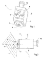
- the Fig. 1 shows a three-dimensional view of a possible embodiment of the thermostat unit 1.
- thermostat unit 1 Under thermostat unit 1 is the complete device with all the individual parts to understand.
- a display 8 for displaying information On an upward surface of the housing 7 of the thermostat unit 1, a display 8 for displaying information is attached.
- the display 8 displays the current room temperature and a symbol for the currently executing mode.
- three key operating elements 9 are arranged on the upward surface. Among the three key operating elements 9 symbols for different modes are attached here, which can be selected with the respective key operating elements 9.
- a light sensor 3 is also mounted on the upwardly facing surface of the thermostat unit 1.
- On a, in installation position vertically oriented surface a thumbwheel 2 is mounted.
- the thumbwheel has a knurl here in the scope to achieve a slip-resistant effect and thus good operability when turning the thumbwheel.
- the symbols "+” and "-” are attached, which explain the user the effect upon rotation of the setting wheel 2.
- the motion sensor 4 In the middle of the setting wheel 2 is the motion sensor 4, which monitors two different detection fields.
- a terminal 10 At another, in installation position vertically oriented surface of the housing 7, a terminal 10 is attached to a radiator.
- the Fig. 2 shows a possible embodiment of the thermostat unit according to the invention in side view.
- the dividing plane 17 here represents the boundary between the two detection areas 5, 6 of the motion sensor 4. In the illustrated case, this dividing plane 17 runs horizontally.
- the detection areas 5, 6 are defined by the respective detection angles ⁇ 1, ⁇ 2.
- Fig. 2 shows a side view of the detection areas 5, 6, which are defined by the two detection angles ⁇ 1, ⁇ 2. In the plan view, ie viewed from above on the surface with the display 8, the detection areas would be represented as semicircles around the movement sensor 4.
- the Fig. 3 shows a flowchart of the method according to the invention.
- the rectangularly framed fields 11, 12, 13 represent different modes.
- a mode is here a partial method for temperature control, with corresponding to the respective mode associated setpoints.
- the diamond-shaped framed panels 14, 15, 16, 40 are actuators in the method. These actuators can be read in the flow chart as queries or decisions.
- the output down from a rhombus is always there for answering the query with "no", lateral outputs from a query mean an answer with "yes”.
- the first mode 11 is activated manually via the actuator 14 "setting wheel”. While running the first mode, the queries are continuously “present?" 15 and "day?" 16 performed. It means "present?" 15 the question of whether there are people in the room.
- the query "day?" 16 determines whether information is stored in the clock and calendar function, which in combination with the current time state that there is sleeping time or no bedtime. Will the query "present?" 15 answered positive, the first mode is retained. Will the query "present?" 15 answered negatively, the next query "day?" 16. If this query is answered in the affirmative, the second mode 12 is activated. Because according to the second query "day?" is no bedtime, is switched to the most economical second mode. Is the query "Tag?" 16 answered negatively, ie it is bedtime, the third mode 13 is activated. Similar contexts then apply to the execution of the second 12 and third 13 modes. The process always goes through two queries 15, 16 and, depending on these queries, the current running mode is either maintained or changed to another mode.
- the exact connections are indicated by the arrows in the flow chart of the Fig. 3 to recognize.
- the above-presented queries 14 and 40 represent the manual actuators and the additional actuator formed by a remote control device acting externally on the thermostat unit. Through these interrogators / actuators 14, 40 it is possible at any time to change the running mode directly , The queries or actuators 14, which are formed by the manual input elements directly to the thermostat unit, highest hierarchy level. This means that via this actuator 14 at any time and contrary to other polling other actuators, a change in the performed Mode according to specification of the actuator, which is formed by the manual input elements on the thermostat unit.
- the interrogations of the actuator 40 formed by a remote control device are in the hierarchy only one level below the actuator 14 and thus allow a change of the executed mode at any time, except when the actuator 14 provides opposite query results.
- Fig. 4 shows a partially sectioned side view of a radiator with an embodiment of a thermostat unit 1 according to the invention with heat meter. It is a radiator to see on the right above a thermostat unit 1 according to the invention is mounted.
- the thermostat unit 1 regulates the heating power of the radiator and thus the room temperature.
- the thermostat unit 1 accesses the valve 24.
- the contact sensor 23 is provided. If the thermostat unit 1 is removed from the radiator, so indicates the contact sensor 23 at.
- a temperature sensor 22 is provided in connection of the thermostat unit 1, which measures the temperature of the heating medium in the flow, ie on the side on which the heating medium, regulated by the thermostat unit 1 flows into the radiator. This measurement of the flow temperature is then required later for the determination of the amount of heat transferred to the radiator.
- another temperature sensor 20 is provided for measuring the temperature of the wake under caster is the heating medium to understand, which flows out again after the delivery of heat in the radiator from the radiator. The temperature of the wake also enters as input information in the calculation of the amount of heat converted to the radiator.
- the temperature sensor 20 is located outside the thermostat unit 1.
- the temperature sensor 20 for measuring the Caster temperature is therefore connected to the thermostat unit 1 through a sensor connection 21.
- This sensor connection 21 can, as in in Fig. 4 represented case are formed by a cable connection. However, it is also possible to realize the sensor terminal 21 by a radio link or the like.
- the data processing unit of the thermostat unit 1 calculates from the flow temperature, determined by the temperature sensor 22, the follow-up temperature, determined by the temperature sensor 20 and the room temperature, determined by the mounted in the thermostat unit 1 temperature sensor, the heat quantity converted to the radiator, which is recorded and stored by the thermostat unit becomes.
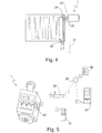
- Fig. 5 shows a schematic representation of the interaction of a thermostat unit according to the invention with other devices.
- the thermostat unit 1 has a transmitting and receiving module 30.
- This transmitting and receiving module 30 enables a data transfer of the thermostat unit 1 with other devices. Under data transfer is to understand that data from both the thermostat unit 1 to the other devices as well as a data transfer from the other devices to the thermostat unit 1 is possible.
- Shown is as possible other device, a radio remote control 31.
- This radio remote control can be used, for example, to change the different modes of operation of the thermostat unit 1 or to turn off the thermostat unit 1 completely.
- a display of various information about room temperature, set temperature, ... on a display of the radio remote control 31 is possible.
- a gateway 32 is a device to understand which communicates on the one hand with one or more thermostat units 1 and on the other side with other devices or a Data network, such as the Internet 34 in connection.
- a gateway 32 thus forms a kind of interface between several communication paths or devices.
- the gateway 32 may be designed to also include a computer suitable for executing programs and calculations and for storing data.
- the gateway 32 is connected to the Internet 34. Via the Internet 34, a connection from the gateway 32 to an external service provider 33 is still possible. Thus, communication from the thermostat unit 1 via the gateway 32 and the Internet 34 to an external service provider 33 is possible.
- This connection can be used, for example, to transmit data on the amount of heat converted to the radiator to an external service provider 33, which then creates the heating bill based on the transmitted amounts of heat.
- a connection of the gateway 32 via the Internet 34 with a remote control device 50 is possible. Through this connection, the thermostat unit 1 can be queried, operated, adjusted or otherwise manipulated from any location connected to the Internet.
- a connection of the thermostat unit 1 to the Internet 34 can also be realized without the path via a gateway 32.
- the transmitting and receiving module 30 may be designed so that it communicates directly with the Internet 34, for example via a mobile or wireless connection.
- the invention comprises:
- a thermostat unit comprising arranged on or in a housing: a temperature sensor, a temperature controller, at least one light sensor, a data processing unit and at least one, at least two detection fields comprising different detection fields, wherein a temperature control is provided based on at least one sensor signal.
- thermostat unit as previously described, wherein the thermostat unit is attachable via a connection directly to a radiator, in particular wherein the position and orientation of the thermostat unit and / or the at least one sensor in the room, based on the connection to the radiator, are adjustable / is and / or in that the position of the detection fields on the motion sensor is adjustable, in particular wherein the detection fields are separated by a separation plane and the detection areas each have a detection angle relative to Have separation plane, in particular wherein the detection angle between 0 ° and 179 °, in particular between 10 ° and 145 ° are preferably provided between 30 ° and 90 ° and / or by an overlap of the detection fields.
- a thermostat unit as previously described, wherein the parting plane is provided substantially horizontally or vertically aligned relative to the housing, and / or in that the motion sensor is designed as an infrared sensor, radar sensor or ultrasonic sensor and / or in that for automatic temperature control at least one, in particular two preferably three different modes are provided and / or in that optionally a signal of the light sensor, the motion sensor, the button controls, the setting wheel and / or the time and calendar function are provided as actuators for the selected mode.
- the motion sensor is designed as an infrared sensor, radar sensor or ultrasonic sensor and / or in that for automatic temperature control at least one, in particular two preferably three different modes are provided and / or in that optionally a signal of the light sensor, the motion sensor, the button controls, the setting wheel and / or the time and calendar function are provided as actuators for the selected mode.
- the invention further comprises a thermostat unit, wherein a temperature sensor (22) for measuring the flow temperature and a temperature sensor (20) for measuring the return temperature are provided and the data processing unit from the measured values of these temperature sensors in combination with the measured value of the temperature sensor, which measures the room temperature , and time information provided by the clock and calendar function calculates the amount of heat that is converted to the radiator whose temperature controls the thermostat unit.
- a previously run thermostat unit wherein the temperature sensor is integrated to measure the flow temperature in the connection of the thermostat unit and the temperature sensor for measuring the return temperature is outside the thermostat unit and a sensor connection with the thermostat unit is connected and this sensor connection is designed as a cable connection or wireless connection.
- the invention further comprises a thermostat unit, wherein a contact sensor is provided in connection, which determines whether the thermostat unit is connected to a valve.
- a as previously executed thermostat unit wherein a transmitting and receiving module is provided which allows data transfer of the thermostat unit with a gateway and / or to the Internet and / or the transmitting and receiving module remote control of the thermostat unit by at least one portable radio remote control and / or by the gateway and / or the Internet allows.
- each mode the data processing unit interrogates an input information of the actuators at defined time intervals and a change of the mode is carried out when changing the input information and / or in that the time intervals of the interrogations of the input information between 0.01 and 5 Minutes, in particular 0.02 and 2 minutes, preferably 0.1 seconds and 30 seconds.
- a remote control device which can assume at least two states, for example a first state and a second state and whose state is determined by the operator, wherein the remote control device in the first state at least one change of modes, a change of stored in the memory set temperatures and / or the Aufstehzeit and switching on and off of the motion sensor allows the remote control device in the second state, a change of stored memory in the memory and / or the switching times for the comfort mode and the Eco mode and a Turning on and off of the motion sensor allows and access of the actuator, embodied by the remote control device to the thermostat unit is possible at any time and this access in the processing hierarchy equivalent or one level lower than the access of the actuator embodied by the manual input elements thumb wheel or button control (e) is.
- the invention also encompasses a use of the thermostat unit according to one of the described embodiments for carrying out the method according to one of the illustrated embodiments.
Abstract
Die Erfindung betrifft eine Thermostateinheit umfassend an oder in einem Gehäuse angeordnet: einen Temperaturfühler, einen Temperaturregler, mindestens einen Lichtsensor, eine Datenverarbeitungseinheit, und mindestens einen, wenigstens zwei voneinander verschiedene Erfassungsfelder umfassenden Bewegungssensor, wobei eine Temperaturregelung basierend auf wenigstens einem Sensorsignal vorgesehen ist und ein Verfahren zur automatischen Regelung der Raumtemperatur.The invention relates to a thermostat unit comprising arranged on or in a housing: a temperature sensor, a temperature controller, at least one light sensor, a data processing unit, and at least one motion sensor comprising at least two different detection fields, wherein a temperature control is provided based on at least one sensor signal and a method for automatically controlling the room temperature.
Description
Die Erfindung betrifft eine sensorgesteuerte Thermostateinheit. Weiterhin betrifft die Erfindung ein Verfahren zur automatischen Regelung der Raumtemperatur mit der zuerst beschriebenen Thermostateinheit.The invention relates to a sensor-controlled thermostat unit. Furthermore, the invention relates to a method for automatically controlling the room temperature with the first described thermostat unit.
Die bedarfsgerechte, automatische Regelung der Raumtemperatur wird in Zeiten hoher Energiekosten und Zielen zur Einsparung von CO2-Emissionen immer wichtiger. Im Bereich der Heizungsthermostate sind bereits seit vielen Jahren elektronisch geregelte Thermostate erhältlich, die die jeweiligen Sollwerte zur Temperaturregelung einer Uhr- und Kalenderfunktion entnehmen. Beispielsweise lassen sich hier Zeiten für eine Nachtabsenkung der Raumtemperatur einprogrammieren, so dass ab einer bestimmten Uhrzeit die Raumtemperatur reduziert wird und am nächsten Morgen ab einer bestimmten Uhrzeit wieder erhöht wird. Nachteilig an dieser Art nur zeitlich gesteuerter Thermostate ist, dass keine Flexibilität gegenüber veränderter Gewohnheiten der Personen, die den Raum benutzen, gegeben ist. So würde an einem Feiertag, der sonst ein Arbeitstag ist, eine normale Temperaturregelung für einen Arbeitstag stattfinden. Der Thermostat würde nicht berücksichtigen, dass Personen abends länger im Raum und aktiv sind und am nächsten Morgen länger schlafen als gewöhnlich. Um die Regelung der Raumtemperatur wieder bedarfsgerecht zu machen, müsste entweder das hinterlegte Programm geändert werden oder auf manuelle Regelung umgeschaltet werden. Ein Umschalten auf manuelle Regelung bringt dann oft mit sich, dass die Automatik nicht mehr aktiviert wird und daher keine Temperaturabsenkung in der Nacht und damit keine Reduzierung der Heizkosten mehr vorgenommen wird.On-demand automatic room temperature control is becoming increasingly important in times of high energy costs and CO 2 emission reduction goals. In the field of heating thermostats have been electronically controlled thermostats for many years available, which take the respective setpoints for temperature control of a clock and calendar function. For example, here times for a night reduction of the room temperature can be programmed, so that from a certain time the room temperature is reduced and the next morning is increased again from a certain time. A disadvantage of this type of time-controlled thermostats is that there is no flexibility against the changed habits of the people who use the room. For example, on a public holiday, which is otherwise a working day, normal temperature control would take place for one working day. The thermostat would not take into account that people are longer in the room and active in the evenings and sleep longer than usual in the morning. In order to make the control of the room temperature as needed again, either the stored program would have to be changed or switched to manual control. Switching over to manual regulation often means that the automatic system is no longer activated and therefore no reduction in temperature at night and thus no reduction in heating costs is made.
Um die bedarfsgerechte Regelung der Raumtemperatur weiter zu verbessern gibt es mehrteilige Systeme für sowohl Wohn- als auch Geschäftsbereiche, die neben der Uhr- und Kalenderfunktion auch noch Signale verschiedener Sensoren zur Regelung verwenden. Diese Systeme weisen eine zentrale Steuereinheit auf, die dann mit räumlich verteilten Sensoren vernetzt werden. Nachteilig an solchen Systemen ist der hohe Aufwand für Einbau und Inbetriebnahme. Weiterhin sind für die Installation Fachkenntnisse im Bereich Netzwerktechnik erforderlich, was den Einbau für den nicht geschulten Anwender weiter erschwert. Dieser hohe Aufwand fällt vor allem beim Nachrüsten von Gebäuden, die bisher eine ältere Technologie verwenden, ins Gewicht. Räumlich verteilte Systeme zeigen den weiteren Nachteil, dass, wenn eine Person in einem Raum manuell in die Temperaturregelung eingreifen will, sie dies meist nur über die zentral angeordnete Steuerung tun kann. Dies ist kompliziert und aufwändig.In order to further improve the demand-based regulation of the room temperature, there are multipart systems for both residential and business areas, which in addition to the clock and calendar function also use signals from various sensors for regulation. These systems have a central control unit, which is then networked with spatially distributed sensors. A disadvantage of such systems is the high cost of installation and commissioning. Furthermore, specialist knowledge in the area of network technology is required for the installation, which further complicates the installation for the untrained user. This high cost is particularly important when retrofitting buildings that previously used an older technology. Spatially distributed systems have the further disadvantage that when a person in a room wants to intervene manually in the temperature control, they this can usually only be done via the centrally arranged controller. This is complicated and expensive.
Die Bewegungssensoren für solche räumlich verteilten Systeme sind meist an den Decken der Räume angebracht und erfassen Bewegungen von oben gesehen nach unten. Somit ist es möglich, dass auch Bewegungen und damit die Anwesenheit von Haustieren, wie zum Beispiel Katzen, erfasst werden und zwar in gleicher Art wie die Anwesenheit von Personen. Die dadurch erzeugten Informationen zur Anwesenheit von Personen führen zu einer Anhebung der Raumtemperatur. Dies ist an dieser Stelle ungewollt, da die für anwesende Menschen angenehme Raumtemperatur beim bloßen Anwesendsein von Haustieren nicht erforderlich ist. Ursache der hier ungewollten Anhebung der Raumtemperatur ist die, dass herkömmliche Bewegungssensoren Mensch und Haustier nicht unterscheiden können, was sich nachteilig auf das Regelverhalten auswirkt.The motion sensors for such spatially distributed systems are usually attached to the ceilings of the rooms and detect movements seen from above down. Thus, it is possible that movements and thus the presence of pets, such as cats, are recorded in the same way as the presence of persons. The information on the presence of persons generated thereby leads to an increase in the room temperature. This is undesirable at this point because the comfortable room temperature for present people is not required for the mere presence of pets. The cause of the unintentional raising of the room temperature is that conventional motion sensors can not distinguish between humans and pets, which has a negative effect on the control behavior.
Ausgehend von diesem Stand der Technik ist es Aufgabe der Erfindung eine sensorgesteuerte Thermostateinheit zur automatischen und bedarfsgerechten Regelung der Raumtemperatur vorzuschlagen, welches mit geringem Aufwand montiert bzw. nachgerüstet werden kann. Die Thermostateinheit soll mit einer höheren Genauigkeit die Anwesenheit von Personen im Raum erkennen und von der Anwesenheit von Haustieren unterscheiden. Weiterhin soll ein Verfahren vorgeschlagen werden, welches unter Verwendung des Thermostats und dessen Sensoren eine intelligente Regelung der Raumtemperatur ermöglicht.Based on this prior art, it is an object of the invention to propose a sensor-controlled thermostat unit for automatic and needs-based control of the room temperature, which can be installed or retrofitted with little effort. The thermostat unit is intended to detect the presence of persons in the room with a higher accuracy and distinguish it from the presence of pets. Furthermore, a method is proposed, which allows using the thermostat and its sensors, an intelligent control of the room temperature.
Die Aufgabe der Erfindung wird gelöst durch eine Thermostateinheit nach dem Anspruch 1 umfassend an oder in einem Gehäuse angeordnet einen Temperaturfühler, einen Temperaturregler, mindestens einen Lichtsensor, eine Datenverarbeitungseinheit, und mindestens einen, wenigstens zwei voneinander verschiedene Erfassungsfelder umfassenden Bewegungssensor, wobei eine Temperaturregelung basierend auf wenigstens einem Sensorsignal vorgesehen ist. Durch die Anordnung in oder an einem einzigen Gehäuse ist die Thermostateinheit kompakt und in nur einem Arbeitsschritt mit sehr wenig Aufwand zu montieren.The object of the invention is achieved by a thermostat unit according to
Die Erfindung umfasst eine Thermostateinheit, die einen Temperaturfühler zur Aufnahme der aktuellen Raumtemperatur aufweist. Die Werte dieses Temperaturfühlers werden kontinuierlich mit dem jeweils anliegenden Sollwert verglichen. Der ebenfalls zur Erfindung gehörige Temperaturregler regelt dann gegebenenfalls die Heizleistung nach, wenn der aktuelle Wert vom Sollwert abweicht. Weiterhin weist die Thermostateinheit mindestens einen Lichtsensor auf. Die Werte dieses Lichtsensors werden als Eingangsinformation dazu verwendet, die Anwesenheit oder Aktivität von Personen im Raum oder die Tageszeit zu erkennen. Die Eingangsinformationen werden von einer Datenverarbeitungseinheit in Signale zur Ansteuerung des Temperaturreglers verarbeitet. Bei der Datenverarbeitungseinheit handelt es sich beispielsweise um eine speicherprogrammierbare Steuerung, die Eingangs- und Ausgangskanäle sowie einen Speicher aufweist. Die Datenverarbeitungseinheit kann programmiert werden, um das gewünschte Regelverhalten der Thermostateinheit einzustellen. Zusätzlich ist mindestens ein Bewegungssensor vorgesehen der wenigstens zwei voneinander verschiedene Erfassungsfelder überwacht. Durch diese beiden verschiedenen Erfassungsfelder ist es möglich, im Raum anwesende Personen von Haustieren zu unterscheiden. Die verschiedenen Erfassungsfelder könnten beispielsweise so eingestellt werden, dass ein Erfassungsfeld nur niedrige/kleine Lebewesen erfasst, indem das Feld beispielsweise auf einen Erfassungsbereich bis 1 m Höhe über dem Boden des Raumes eingestellt wird. Das zweite Erfassungsfeld wird dann auf einen Bereich von ab 1 m Höhe über dem Boden des Raumes eingestellt. Menschliche Aktivität wird von der Datenverarbeitungseinheit dann nur festgestellt wenn Bewegung in beiden Erfassungsfeldern erkannt wird. Wird nur Bewegung in einem Erfassungsfeld erkannt, liegt keine Anwesenheit von Personen im Raum vor. Die Grenze zwischen den beiden Erfassungsfeldern kann selbstverständlich auch auf eine andere Art gestaltet werden. Die erfindungsgemäße Thermostateinheit führt eine Regelung der Raumtemperatur basierend auf wenigstens einem Sensorsignal aus. Bei diesem wenigstens einem Sensorsignal kann es sich um ein Signal eines Lichtsensors oder eines Bewegungssensors handeln.The invention comprises a thermostat unit having a temperature sensor for receiving the current room temperature. The values of this temperature sensor are continuously compared with the respective setpoint. The temperature controller, which is also part of the invention, then optionally regulates the heating power if the current value deviates from the desired value. Furthermore, the thermostat unit has at least one light sensor. The values of this light sensor are used as input information to detect the presence or activity of persons in the room or the time of day. The input information is processed by a data processing unit into signals for controlling the temperature controller. The data processing unit is, for example, a programmable logic controller having input and output channels and a memory. The data processing unit can be programmed to set the desired control behavior of the thermostat unit. In addition, at least one motion sensor is provided which monitors at least two mutually different detection fields. These two different fields of coverage make it possible to distinguish persons present in the room from pets. For example, the different detection fields could be set such that a detection field only detects low / small organisms, for example by setting the field to a detection range of up to 1 m above the floor of the room. The second detection field is then set to a range from 1 m above the floor of the room. Human activity is then detected by the computing device only if motion is detected in both detection fields becomes. If only movement in a detection field is detected, there is no presence of persons in the room. Of course, the border between the two fields can also be designed in a different way. The thermostat unit according to the invention performs a control of the room temperature based on at least one sensor signal. This at least one sensor signal may be a signal of a light sensor or of a motion sensor.
Des Weiteren ist vorgesehen, dass die Datenverarbeitungseinheit eine Uhrzeit- und Kalenderfunktion sowie einen Speicher umfasst. In diesem Speicher können dann sowohl Sollwerte für die Temperaturregelung als auch Zeit-und Datumswerte abgelegt werden. Somit ist es möglich, die Temperaturregelung auch über einprogrammierte Termine zu beeinflussen. So können beispielsweise Urlaubszeiten abgespeichert werden, in denen andere, niedrigere Solltemperaturen ausgeregelt werden. Auch übliche Uhrzeiten für die Übergänge zwischen Tag und Nacht bzw. Aktivität oder Nichtaktivität von Personen im Raum können so abgespeichert werden. Durch die Uhrzeit- und Kalenderfunktion ist es der Thermostateinheit dann stets möglich, einen im Speicher abgelegten Sollwert zur Temperaturregelung anzulegen. Weiterhin können alle Sollwerte zur Temperaturregelung immer wieder bedarfsgemäß geändert werden.Furthermore, it is provided that the data processing unit comprises a time and calendar function and a memory. In this memory then both setpoints for the temperature control as well as time and date values can be stored. This makes it possible to influence the temperature control via programmed appointments. For example, holiday periods can be stored in which other, lower setpoint temperatures are corrected. Also common times for the transitions between day and night or activity or non-activity of people in the room can be stored. Due to the clock and calendar function, it is then always possible for the thermostat unit to apply a setpoint stored in the memory for temperature control. Furthermore, all setpoints for temperature control can always be changed as needed.
In einer vorteilhaften Ausgestaltung ist vorgesehen, dass die Thermostateinheit ein Eingabeelement, insbesondere ein Stellrad aufweist. Dieses Stellrad ist zur manuellen Einstellung der Temperatur einsetzbar. Ist eine im Raum anwesende Person nicht zufrieden mit der vorliegenden Raumtemperatur, kann sie mithilfe des Stellrades, ohne sich mit der Programmierung der Thermostateinheit beschäftigen zu müssen, die Raumtemperatur direkt manuell abändern. Weiterhin ist es möglich durch das Stellrad die Sollwerte im Speicher der Datenverarbeitungseinheit abzuändern und damit die Regelungseigenschaften im Automatikbetrieb zu beeinflussen. Auch die Uhrzeit- und Datumswerte im Speicher der Datenverarbeitungseinheit können über das Stellrad benutzerfreundlich verändert werden. Auch ein Ausschalten der gesamten Thermostateinheit ist über das Stellrad möglich. Dies könnte beispielsweise über einen Schalter in einer Endlage des Stellrades realisiert werden, ohne die Erfindung auf diese Lösung zu beschränken. Dadurch ist der Vorteil gegeben, dass sich die Thermostateinheit auch von Personen, die mit den Details der Thermostateinheit nicht vertraut sind, jederzeit einfach ausschalten lässt. Weiterhin ist es möglich, die Empfindlichkeit mindestens eines der Sensoren über das Stellrad zu beeinflussen. Dies ermöglicht, dass beispielsweise der Lichtsensor an die Helligkeitsbedingungen seiner Einbaulage angepasst werden kann. Die Erfindung ist selbstverständlich nicht nur auf ein Stellrad als Eingabeelement beschränkt. Es können auch verschiedene andere Eingabeelemente wie Stellschieber, Drehschalter oder Stellhebel eingesetzt werden.In an advantageous embodiment it is provided that the thermostat unit has an input element, in particular a thumbwheel. This setting wheel can be used to manually set the temperature. If a person present in the room is not satisfied with the room temperature at hand, the room temperature can be changed manually without having to worry about programming the thermostat unit. Furthermore, it is possible by the setting wheel, the setpoints in the memory of the data processing unit modify and thus influence the control characteristics in automatic mode. The time and date values in the memory of the data processing unit can be changed user-friendly via the setting wheel. It is also possible to switch off the entire thermostat unit via the setting wheel. This could be realized for example via a switch in an end position of the setting wheel, without limiting the invention to this solution. This gives the advantage that the thermostat unit can be easily switched off at any time even by persons who are unfamiliar with the details of the thermostat unit. Furthermore, it is possible to influence the sensitivity of at least one of the sensors via the setting wheel. This makes it possible, for example, for the light sensor to be adapted to the brightness conditions of its installation position. Of course, the invention is not limited to an adjusting wheel as an input element. It can also be used various other input elements such as lock slider, rotary switch or lever.
In einer weiteren bevorzugten Ausführungsform ist vorgesehen, dass die Thermostateinheit wenigstens ein Display und/oder wenigstens ein Tastenbedienelement aufweist. Ein Display ermöglicht die Anzeige der aktuellen Soll- und Ist-Temperatur. Weiterhin sind andere nützliche Informationen wie beispielsweise die Art des anliegenden Betriebsmodus oder Datum und Uhrzeit darstellbar. Auch können bei der Programmierung der Thermostateinheit die Parameter auf dem Display angezeigt werden. Die Aufgaben des Displays können ebenso durch Kontrolllampen, Leuchtdioden oder andere Anzeigeelemente realisiert werden.
Über ein oder mehrere Tastenbedienelemente wird gewährleistet, dass unterschiedliche Modi der Temperaturregelung durch einen einfachen Knopfdruck direkt ausgewählt werden können. Weiterhin können Sollwerte für die Temperatur oder Zeit-und Datumswerte über die Tastenbedienelemente in den Speicher der Datenverarbeitungseinheit eingegeben werden. Die Eingaben können auch über Kipphebel, Wärmesensoren oder ein Touchpad, wie es beispielsweise bei Smartphones eingesetzt wird, erfolgen. Die Eingaben sind selbstverständlich auch in Kombination mit dem Stellrad möglich.In a further preferred embodiment, it is provided that the thermostat unit has at least one display and / or at least one key operating element. A display enables the display of the current setpoint and actual temperature. Furthermore, other useful information such as the type of applied operating mode or date and time can be displayed. Also, when programming the thermostat unit, the parameters can be shown on the display. The tasks of the display can also be realized by control lamps, LEDs or other display elements.
One or more key controls ensure that different modes of temperature control can be selected directly by simply pressing a button. Furthermore, setpoints for the temperature or time and date values can be stored in the memory of the key presses Data processing unit to be entered. The inputs can also be via rocker arms, thermal sensors or a touchpad, as it is used for example in smartphones. Of course, the entries are also possible in combination with the setting wheel.
Des Weiteren ist vorgesehen, dass wenigstens ein Lichtsensor auf einer Oberseite des Gehäuses der Thermostateinheit vorgesehen ist ohne die Erfindung hierauf zu beschränken. Die Anordnung oben auf der Einheit ermöglicht eine optimale Erfassung von Licht, da sowohl Tageslicht als auch künstliches Licht von oben ausgesendet wird. Das Gehäuse kann so den Erfassungsbereich des Lichtsensors nicht verdecken.Furthermore, it is provided that at least one light sensor is provided on an upper side of the housing of the thermostat unit without limiting the invention thereto. The arrangement on top of the unit allows optimal detection of light, as both daylight and artificial light is emitted from above. The housing can thus not obscure the detection range of the light sensor.
Vorteilhafter Weise ist vorgesehen, dass eine automatische Regelung der Thermostateinheit durch die Datenverarbeitungseinheit auf Basis der Signale mindestens eines Lichtsensors vorgesehen ist. Die vom Lichtsensor erkannten Helligkeiten werden von der Datenverarbeitungseinheit in Informationen umgearbeitet, die in eine Aussage zur Anwesenheit von aktiven Personen im Raum einwirken. So kann beispielsweise beim Registrieren höherer Helligkeit in der Nacht darauf geschlossen werden, dass künstliches Licht angeschaltet wurde. Dies gibt wiederum Hinweis auf die Aktivität von Personen im Raum und bewirkt die Anhebung der Temperatur.Advantageously, it is provided that an automatic control of the thermostat unit is provided by the data processing unit based on the signals of at least one light sensor. The brightnesses detected by the light sensor are converted by the data processing unit into information that influences the presence of active persons in the room. For example, when registering higher brightness at night, it can be concluded that artificial light has been turned on. This in turn indicates the activity of people in the room and causes the temperature to rise.
Des Weiteren ist in dem Vorschlag vorteilhafter Weise vorgesehen, dass die Signale des mindestens einen Lichtsensors mit im Speicher hinterlegten Datensätzen aus Licht- und Dunkelphasen kombiniert werden. Es ist möglich, im Speicher der Thermostateinheit Datensätze mit Beginn und Ende der Tageslichtdauer abhängig von Datum und Jahreszeit abzulegen. Durch die Kenntnis, zu welchen Zeiten Tageslicht vorhanden ist, und somit vom Lichtsensor registrierte Helligkeit nicht zwingend Ursache von Aktivität von Personen im Raum sein muss, kann die Genauigkeit zum Erkennen von aktiven Personen im Raum weiter verbessert werden.Furthermore, it is advantageously provided in the proposal that the signals of the at least one light sensor are combined with stored in the memory records of light and dark phases. It is possible to store in the memory of the thermostat unit records with the beginning and end of the daylight duration depending on date and season. By knowing at which times daylight is present, and thus brightness registered by the light sensor is not necessarily the cause of activity of Persons must be in the room, the accuracy for detecting active people in the room can be further improved.
Des Weiteren ist vorgesehen, dass die Thermostateinheit über einen Anschluss direkt an einem Heizkörper anbringbar ist. Es ist somit eine sehr einfache Montage der Thermostateinheit gewährleistet. Durch die Verwendung von genormten Anschlüssen kann die Thermostateinheit in gleicher Art wie ein gewöhnlicher, manueller Drehthermostat angebracht werden, bspw. über Schiebemuffen, Unterwurfmuffen oder dergleichen. Spezielles Fachwissen ist bei der Anbringung der Thermostateinheit also nicht erforderlich.Furthermore, it is provided that the thermostat unit can be attached directly to a radiator via a connection. It is thus ensured a very simple installation of the thermostat unit. Through the use of standardized connections, the thermostat unit can be mounted in the same manner as an ordinary, manual rotary thermostat, for example via sliding sleeves, Unterwurfmuffen or the like. Special expertise is therefore not required when mounting the thermostat unit.
Bei einer bevorzugten Ausgestaltung des Vorschlags ist vorgesehen, dass Lage und Ausrichtung der Thermostateinheit und/oder des wenigstes einen Sensors im Raum bezogen auf den Anschluss am Heizkörper einstellbar sind/ist. Vorteil dieser Eigenschaft ist der, dass je nach Einbaulage am Heizkörper die Erfassungsbereiche der Sensoren im Raum individuell und optimal ausgerichtet werden können. Dies ist wichtig für eine hohe Genauigkeit beim Erkennen von aktiven Personen im Raum.In a preferred embodiment of the proposal it is provided that the position and orientation of the thermostat unit and / or the least one sensor in the room relative to the connection to the radiator are / is adjustable. Advantage of this feature is that depending on the installation position on the radiator, the detection ranges of the sensors in the room can be individually and optimally aligned. This is important for high accuracy in detecting active people in the room.
Des Weiteren ist vorgesehen, dass die Lage eines oder beider Erfassungsfelder am Bewegungssensor einstellbar ist. Dieses Merkmal dient dazu die Genauigkeit beim Erkennen von Personen im Raum zu optimieren. Durch eine Einstellbarkeit der Erfassungsfelder wird eine optimale Trennung zwischen dem Erkennen von Personen und dem Erkennen von bspw. Haustieren gewährleistet.Furthermore, it is provided that the position of one or both detection fields on the motion sensor is adjustable. This feature is used to optimize the accuracy of recognizing people in the room. An adjustability of the detection fields ensures an optimal separation between the recognition of persons and the recognition of, for example, domestic animals.
Bei einer bevorzugten Ausgestaltung des Vorschlags ist vorgesehen, dass die Erfassungsfelder durch eine Trennebene getrennt sind und die Erfassungsbereiche je einen Erfassungswinkel relativ zur Trennebene aufweisen. Die Trennebene schließt in dieser Ausführungsform aus, dass sich die Erfassungsbereiche durchdringen oder überlappen. Die Trennebene ist in einer bevorzugten Ausführungsform relativ zum Gehäuse im Wesentlichen horizontal oder vertikal ausgerichtet vorgesehen. Für eine genaue Unterscheidung zwischen der Anwesenheit von Personen und der Anwesenheit von Haustieren hat sich eine im Raum horizontal ausgerichtete Trennebene zwischen den Erfassungsfeldern als besonders günstig herausgestellt. Durch eine Anordnung der Trennebene horizontal oder vertikal zum Gehäuse der Thermostateinheit kann die gesamte Thermostateinheit in ihrer Einbaulage variiert werden, was wiederum die Montage in verschiedenen Einbausituationen oder bei verschiedenen Heizkörperausführungen erleichtert. Die über die Erfassungswinkel eindeutig definierten und einstellbaren Erfassungsbereiche liefern so unabhängige Informationen über Bewegungen im Raum. Die Erfassungswinkel der Erfassungsbereiche liegen dabei zwischen 0° und 179°. In der Praxis haben sich allerdings insbesondere Erfassungswinkel zwischen 10° und 145°, bevorzugt Winkel zwischen 30° und 90° als günstig zur genauen Erkennung von aktiven Personen im Raum herausgestellt. Selbstverständlich sind erfindungsgemäß auch andere Erfassungswinkel und Lagen der Trennebene möglich.In a preferred embodiment of the proposal, it is provided that the detection fields are separated by a parting plane and the detection areas each have a detection angle relative to the parting plane. The parting plane in this embodiment excludes that the detection areas penetrate or overlap. The parting plane is in a preferred Embodiment provided relative to the housing substantially horizontally or vertically aligned. For a precise distinction between the presence of persons and the presence of pets, a horizontally aligned separation plane between the detection fields has proven to be particularly favorable. By arranging the parting plane horizontally or vertically to the housing of the thermostat unit, the entire thermostat unit can be varied in its installation position, which in turn facilitates the assembly in different installation situations or in different radiator designs. The detection areas clearly defined and adjustable via the detection angles thus provide independent information about movements in the room. The detection angles of the detection ranges are between 0 ° and 179 °. In practice, however, in particular detection angle between 10 ° and 145 °, preferably angles between 30 ° and 90 ° have been found to be favorable for the accurate detection of active persons in the room. Of course, according to the invention, other detection angles and positions of the parting plane are possible.
Eine weitere Ausführungsform sieht vor, dass sich die Erfassungsfelder auch überlappen können. Bewegungen, die in dem entstehenden Überlappungsbereich stattfinden werden dann von beiden Erkennungsfeldern wahrgenommen.Another embodiment provides that the detection fields can also overlap. Movements that take place in the resulting overlap area are then perceived by both detection fields.
Geschickter Weise ist vorgesehen, dass der Bewegungssensor als Infrarotsensor, Radarsensor oder Ultraschallsensor ausgebildet ist. Darüber hinaus ist es natürlich auch möglich, andersartig geeignete Bewegungssensoren in der erfindungsgemäßen Thermostateinheit einzusetzen.Clever way is provided that the motion sensor is designed as an infrared sensor, radar sensor or ultrasonic sensor. In addition, it is of course also possible to use other suitable motion sensors in the thermostat unit according to the invention.
Des Weiteren ist vorgesehen, dass zur automatischen Temperaturregelung wenigstens ein, insbesondere zwei, bevorzugt drei unterschiedliche Modi vorgesehen sind. Unter Modus ist hier ein separater Programmbereich der Datenverarbeitungseinheit zu verstehen, in dem jeweils eigene Sollwerte für die Temperaturregelung hinterlegt sind. Beispielsweise könnte ein solcher Modus für die Regelung der Raumtemperatur bei Anwesenheit von Personen und ein anderer Modus zur Regelung der Raumtemperatur bei Abwesenheit von Personen eingenommen werden. Die Strukturierung der Temperaturregelung in unterschiedliche Modi bringt den Vorteil, dass die Programmierung einfacher und leichter verständlich ist. Weiterhin ist das manuelle Eingreifen in die automatische Regelung durch das Vorhandensein unterschiedlicher Modi einfacher, so dass beispielsweise per Knopfdruck sofort ein anderer Satz von Sollwerten zur Temperaturregelung ausgewählt werden kann.Furthermore, it is provided that at least one, in particular two, preferably three different modes are provided for the automatic temperature control. Under mode is here to understand a separate program area of the data processing unit, in each of which own setpoints for the temperature control are stored. For example, such a mode could be adopted for the control of the room temperature in the presence of persons and another mode for controlling the room temperature in the absence of persons. The structuring of the temperature control in different modes has the advantage that the programming is easier and easier to understand. Furthermore, the manual intervention in the automatic control by the presence of different modes is easier, so that for example by pressing a button immediately another set of setpoints for temperature control can be selected.
Des Weiteren ist günstiger Weise vorgesehen, dass wahlweise ein Signal des Lichtsensors, des Bewegungssensors, der Tastenbedienelemente, des Stellrades und/oder der Zeit- und Kalenderfunktion als Stellglieder für den ausgewählten Modus vorgesehen sind. Diese Stellglieder sind hier als Auslöser oder Trigger zum Wechsel in einen anderen Modus zu betrachten. Bei der erfindungsgemäßen Thermostateinheit kann also sowohl ein manuelles Signal, wie beispielsweise der Druck auf eine Taste, als auch ein automatisch generiertes Signal, wie beispielsweise das Erkennen einer sich bewegenden Person im Raum durch einen Bewegungssensor einen Wechsel des Modus und dadurch des Regelverhaltens auslösen.Furthermore, it is advantageously provided that selectively a signal of the light sensor, the motion sensor, the button controls, the setting wheel and / or the time and calendar function are provided as actuators for the selected mode. These actuators are to be considered here as a trigger or trigger to change to another mode. In the thermostat unit according to the invention can therefore trigger both a manual signal, such as the pressure on a button, as well as an automatically generated signal, such as the detection of a person moving in space by a motion sensor, a change of mode and thereby the control behavior.
Geschickter Weise ist vorgesehen, dass ein Temperatursensor zur Messung der Vorlauftemperatur und ein Temperatursensor zur Messung der Rücklauftemperatur vorgesehen sind und die Datenverarbeitungseinheit aus den Messwerten dieser Temperatursensoren in Kombination mit dem Messwert des Temperaturfühlers, der die Raumtemperatur misst, und einer Zeitinformation, die von der Uhrzeit- und Kalenderfunktion bereitgestellt wird, die Wärmemenge berechnet, die an dem Heizkörper, dessen Temperatur die Thermostateinheit regelt, umgesetzt wird. In dieser Ausführungsform sind zwei weitere Temperatursensoren vorgesehen, die die Temperatur des Heizmediums am Vorlauf sowie am Rücklauf des Heizkörpers messen, welcher von der Thermostateinheit geregelt wird. Die Differenz zwischen Vorlauf- und Rücklauftemperatur sagt aus, in welchem Maß das Heizmedium beim Durchlaufen des Heizkörpers abgekühlt ist. In Kombination mit der Information des in der Thermostateinheit verbauten Temperaturfühlers, welcher die aktuelle Raumtemperatur misst, ist eine Berechnung der am Heizkörper umgesetzten Wärmemenge gemäß der europäischen Norm EN 834 möglich. Ebenfalls zur Erfindung gehörend ist das Vorsehen eines zusätzlichen Messelementes für den Volumenstrom durch den Heizkörper, beispielsweise in Form eines Flügelrades oder eines Venturi-Rohres.
Besonders vorteilhaft an dieser Ausführungsform ist die Funktionsvereinigung zweier Geräte innerhalb der Thermostateinheit: zum einen regelt die Thermostateinheit komfortabel und automatisch die Raumtemperatur. Zum anderen ermittelt die Thermostateinheit gleichzeitig die umgesetzte Wärmemenge, die für die Berechnung der anfallenden Heizkosten benötigt wird. Aktuell wird diese Berechnung der Wärmemenge meist von separaten Geräten durchgeführt, was einen erhöhten Aufwand, auch in finanzieller Hinsicht, bedeutet. Mit einer Integration einer Möglichkeit zur Wärmemengenmessung in einer Thermostateinheit kann ein zusätzliches Gerät zur Feststellung der verbrauchten Wärmemenge eingespart werden. Eine Integration der Wärmemengenmessung in die Thermostateinheit hat weitere Vorteile. Separate Geräte zur Messung der Wärmemenge haben oft das Problem, dass sie bei niedrigen Vorlauftemperaturen oder bei geringen Differenzen zwischen Vor- und Nachlauftemperatur nicht erkennen können, ob der entsprechende Heizkörper überhaupt von Heizmedium durchströmt wird oder nicht. Es kann daher bei separaten Geräten zur Messung der Wärmemenge vorkommen, dass eine umgesetzte Wärmemenge berechnet wird, obwohl das Ventil des Heizkörpers komplett geschlossen ist und dieser gar nicht von Heizmedium durchströmt wird. Eine erfindungsgemäße Thermostateinheit erkennt die Ventilstellung des Heizkörpers und hat somit jederzeit eine verlässliche Information zur Verfügung, ob der Heizkörper von Heizmedium durchströmt wird oder nicht.In a clever way it is provided that a temperature sensor for measuring the flow temperature and a temperature sensor for measuring the return temperature are provided and the data processing unit from the measured values of these temperature sensors in combination with the measured value of the temperature sensor, which measures the room temperature, and a time information, the time and calendar function is calculated, the amount of heat calculated at the Radiator whose temperature controls the thermostat unit is implemented. In this embodiment, two further temperature sensors are provided which measure the temperature of the heating medium at the flow and at the return of the radiator, which is controlled by the thermostat unit. The difference between flow and return temperature indicates to what extent the heating medium has cooled when passing through the radiator. In combination with the information of the temperature sensor installed in the thermostat unit, which measures the current room temperature, it is possible to calculate the amount of heat transferred to the radiator according to the European standard EN 834. Also part of the invention is the provision of an additional measuring element for the volume flow through the radiator, for example in the form of an impeller or a Venturi tube.
The functional combination of two devices within the thermostat unit is particularly advantageous in this embodiment: on the one hand, the thermostat unit comfortably and automatically regulates the room temperature. On the other hand, the thermostat unit simultaneously determines the amount of heat needed to calculate the heating costs incurred. Currently, this calculation of the amount of heat is usually carried out by separate devices, which means an increased effort, also in financial terms. With an integration of a possibility for heat quantity measurement in a thermostat unit, an additional device for determining the amount of heat consumed can be saved. An integration of the heat quantity measurement in the thermostat unit has further advantages. Separate devices for measuring the amount of heat often have the problem that they can not detect at low flow temperatures or small differences between flow and tail temperature, whether the corresponding radiator is flowed through by heating medium or not. It may therefore occur in separate devices for measuring the amount of heat that a converted Amount of heat is calculated, although the valve of the radiator is completely closed and this is not flowed through by heating medium. A thermostat unit according to the invention detects the valve position of the radiator and thus always has reliable information available whether the radiator is flowed through by heating medium or not.
Bei einer bevorzugten Ausgestaltung der Erfindung ist vorgesehen, dass der Temperatursensor zur Messung der Vorlauftemperatur in den Anschluss der Thermostateinheit integriert ist und der Temperatursensor zur Messung der Rücklauftemperatur sich außerhalb der Thermostateinheit befindet und über einen Sensoranschluss mit der Thermostateinheit verbunden ist und dieser Sensoranschluss als Kabelverbindung oder Drahtlosverbindung ausgeführt ist. In dieser Ausführungsform der Erfindung ist ein Sensor zur Messung der Vorlauftemperatur in der Thermostateinheit bzw. im Anschluss der Thermostateinheit an den Heizkörper integriert. Dieser Sensor ist innerhalb der Thermostateinheit mit der Datenverarbeitungseinheit zur Informationsübertragung verbunden. Ein weiterer Sensor befindet sich außerhalb der Thermostateinheit und ist am Rücklauf des Heizkörpers zur Messung der Rücklauftemperatur angebracht. Dieser Sensor zur Messung der Rücklauftemperatur ist über einen Sensoranschluss mit der Thermostateinheit zur Informationsübertragung verbunden. Der Sensoranschluss kann dabei als Kabelverbindung oder aber auch als Funkverbindung ausgebildet sein.In a preferred embodiment of the invention it is provided that the temperature sensor for measuring the flow temperature is integrated into the connection of the thermostat unit and the temperature sensor for measuring the return temperature is outside the thermostat unit and is connected via a sensor connection to the thermostat unit and this sensor connection as a cable connection or Wireless connection is performed. In this embodiment of the invention, a sensor for measuring the flow temperature in the thermostat unit or after the thermostat unit is integrated with the radiator. This sensor is connected within the thermostat unit to the data processing unit for transmitting information. Another sensor is located outside the thermostat unit and is attached to the return flow of the radiator to measure the return temperature. This sensor for measuring the return temperature is connected via a sensor connection to the thermostat unit for transmitting information. The sensor connection can be designed as a cable connection or as a radio connection.
Des Weiteren ist günstiger Weise vorgesehen, dass ein Kontaktsensor im Anschluss vorgesehen ist, der ermittelt, ob die Thermostateinheit an einem Ventil angeschlossen ist. In dieser Ausführung der Erfindung ist ein Kontaktsensor vorgesehen, der erkennen kann, ob die Thermostateinheit tatsächlich an einem Ventil eines Heizkörpers angeschlossen ist. Bei einer Verwendung der Thermostateinheit als Wärmemengenmesser, wie es weiter oben beschrieben wurde, wäre es möglich, die Thermostateinheit vom Heizkörper zu entfernen um die umgesetzte Wärmemenge absichtlich nicht zu erfassen. Im Fall der Abrechnung der Heizkosten anhand der umgesetzten und von der Thermostateinheit ermittelten Wärmemenge könnten so die anfallenden Heizkosten manipuliert werden. Um eine derartige Manipulation der Heizkosten entgegenzuwirken, ist der Kontaktsensor in der Thermostateinheit vorgesehen. Für den Fall, dass dieser Kontaktsensor erkennt, dass er nicht an einem Heizkörperventil angeschlossen ist wird für die Berechnung der umgesetzten Wärmemenge der maximal mögliche Volumenstrom durch das Heizkörperventil angenommen. Die Zusammenhänge zwischen den Signalen des Kontaktsensors und der daraus abzuleitenden Annahmen und Aktionen sind als Programm im Speicher der Datenverarbeitungseinheit der Thermostateinheit hinterlegt. Somit wird bei einer absichtlichen Demontage der Thermostateinheit vom Heizkörper nicht gar kein Volumenstrom und damit gar keine Wärmemenge erfasst sondern es wird der maximal mögliche Volumenstrom und damit die maximal mögliche Wärmemenge von der Thermostateinheit erfasst und aufgezeichnet. Ein Nutzer, der die Thermostateinheit vom Heizkörper demontiert um dadurch Heizkosten einzusparen erreicht damit genau das Gegenteil: durch die Demontage der Thermostateinheit vom Heizkörper wird automatisch die maximal mögliche Wärmemenge aufgezeichnet, was zu keiner Einsparung bei den Heizkosten führt sondern im Gegenteil zu höheren Heizkosten als im Normalbetrieb führen dürfte. Das Vorsehen eines Kontaktsensors, der erkennt ob die Thermostateinheit an einem Heizkörperventil angeschlossen ist verhindert somit effektiv und einfach eine Manipulation der Heizkostenabrechnung durch Bewohner der beheizten Räume.Furthermore, it is advantageously provided that a contact sensor is provided in the connection, which determines whether the thermostat unit is connected to a valve. In this embodiment of the invention, a contact sensor is provided which can detect whether the thermostat unit is actually connected to a valve of a radiator. When using the thermostat unit as a heat meter, as above described, it would be possible to remove the thermostat unit from the radiator to intentionally not detect the amount of heat converted. In the case of billing the heating costs on the basis of the converted and determined by the thermostat unit amount of heat so the resulting heating costs could be manipulated. In order to counteract such a manipulation of the heating costs, the contact sensor is provided in the thermostat unit. In the event that this contact sensor detects that it is not connected to a radiator valve, the maximum possible volume flow through the radiator valve is assumed for the calculation of the amount of heat converted. The relationships between the signals of the contact sensor and the assumptions and actions to be derived therefrom are stored as a program in the memory of the data processing unit of the thermostat unit. Thus, at a deliberate disassembly of the thermostat unit from the radiator not even no flow and thus no amount of heat detected but it is the maximum possible flow and thus the maximum amount of heat detected by the thermostat unit and recorded. A user who dismantles the thermostat unit from the radiator thereby saving heating costs achieved exactly the opposite: by dismantling the thermostat unit from the radiator, the maximum possible amount of heat is automatically recorded, resulting in no saving in heating costs but on the contrary to higher heating costs than in Normal operation should lead. The provision of a contact sensor, which detects whether the thermostat unit is connected to a radiator valve thus effectively and simply prevents manipulation of the heating bill by residents of the heated rooms.
Vorteilhafter Weise ist vorgesehen, dass ein Sende- und Empfangsmodul vorgesehen ist, welches Datentransfer der Thermostateinheit mit einem Gateway und/oder mit dem Internet ermöglicht und/oder das Sende- und Empfangsmodul eine Fernbedienung der Thermostateinheit durch mindestens eine portable Funkfernbedienung und/oder durch den Gateway und/oder über das Internet ermöglicht. In dieser Ausführungsform ist in der Thermostateinheit oder direkt an der Thermostateinheit angebracht, ein Sende- und Empfangsmodul vorgesehen, welches Kommunikation und Datentransfer der Thermostateinheit mit anderen Geräten ermöglicht. Bei diesen anderen Geräten kann es sich beispielsweise um einen Gateway handeln, welcher zur Steuerung und Regelung einer oder mehrerer Thermostateinheiten, auch verschiedener Bauart, vorgesehen ist. Dieser Gateway kann dabei auch mit dem Internet verbunden sein, wobei dann über den Gateway eine Kommunikation der Thermostateinheit mit dem Internet möglich ist. Es ist allerdings auch möglich, dass das Sende- und Empfangsmodul der Thermostateinheit so ausgeführt ist, dass es ohne Gateway direkt mit dem Internet kommuniziert. Dies könnte beispielsweise über eine Mobilfunkverbindung erfolgen. Weiterhin bietet das Vorsehen eines Sende- und Empfangsmoduls in der Thermostateinheit die Möglichkeit der Fernbedienung der Thermostateinheit. Eine derartige Fernbedienung kann beispielsweise direkt über eine oder mehrere Funkfernbedienungen erfolgen. Solche Funkfernbedienungen, die ähnlich der Funkfernbedienungen für Fernsehgeräte gestaltet sein können, ermöglichen die Einflussnahme auf die Thermostateinheit ohne direkten Zugang zu der Thermostateinheit haben zu müssen. Dies erhöht deutlich den Komfort bei der Bedienung der Thermostateinheit, gerade wenn die Thermostateinheit an schwer zugänglichen Heizkörpern angebracht ist. Weiterhin ist eine Fernbedienung der Thermostateinheit mithilfe des Sende- und Empfangsmoduls auch über einen Gateway möglich. Der Gateway kann dabei so gestaltet sein, dass eine Software eine zentrale Regelung und Überwachung mehrerer Thermostateinheit übernimmt. Der Bediener oder Hausbesitzer kann dann über diese zentrale Software und den Gateway von einer Stelle aus alle Thermostateinheit komfortabel bedienen, einstellen und überwachen. Darüber hinaus ist durch das Sende- und Empfangsmodul eine Fernbedienung der Thermostateinheit auch vom Internet aus möglich. Diese Fernbedienung der Thermostateinheit kann entweder vom Internet aus über den Gateway, oder auch direkt erfolgen. Als Eingabegeräte für eine Fernbedienung der Thermostateinheit über das Internet sind alle möglichen Datenverarbeitungsgeräte denkbar. So kann die Fernbedienung über einen am Internet angeschlossenen PC oder ein über eine Funkverbindung mit dem Internet verbundenes Notebook erfolgen. Weiterhin sind selbstverständlich auch mobile, internetfähige Geräte zur Fernbedienung der Thermostateinheit denkbar, wie beispielsweise Smartphones. Die Fernbedienung kann über entsprechende Software oder Apps erfolgen. Besonders komfortabel und benutzerfreundlich sind dabei Programme oder Apps mit einer grafischen Benutzeroberfläche, die beispielsweise ähnlich der Tastenbedienelemente, die direkt an der Thermostateinheit angebracht sind, gestaltet sein können.Advantageously, it is provided that a transmitting and receiving module is provided which allows data transfer of the thermostat unit with a gateway and / or to the Internet and / or the transmitting and receiving module Remote control of the thermostat unit by at least one portable wireless remote control and / or through the gateway and / or the Internet allows. In this embodiment, a transmitting and receiving module is provided in the thermostat unit or mounted directly on the thermostat unit, which allows communication and data transfer of the thermostat unit with other devices. These other devices may be, for example, a gateway, which is provided for the control and regulation of one or more thermostat units, including various types. This gateway can also be connected to the Internet, in which case a communication of the thermostat unit with the Internet is possible via the gateway. However, it is also possible that the transmitting and receiving module of the thermostat unit is designed so that it communicates directly with the Internet without a gateway. This could be done for example via a mobile connection. Furthermore, the provision of a transmitting and receiving module in the thermostat unit offers the possibility of remote control of the thermostat unit. Such a remote control can for example be done directly via one or more radio remote controls. Such radio remote controls, which may be similar to the radio remote controls for televisions, allow the influence on the thermostat unit without having to have direct access to the thermostat unit. This significantly increases the convenience of operating the thermostat unit, especially when the thermostat unit is mounted on hard to reach radiators. Furthermore, a remote control of the thermostat unit using the transmit and receive module is also possible via a gateway. The gateway can be designed in such a way that software handles central control and monitoring of several thermostat units. The operator or homeowner can then conveniently operate, set and monitor all the thermostat units from one location via this central software and the gateway. In addition, by the transmitting and receiving module, a remote control of the thermostat unit also possible from the internet. This remote control of the thermostat unit can be done either from the Internet via the gateway, or directly. As input devices for a remote control of the thermostat unit via the Internet, all possible data processing devices are conceivable. Thus, the remote control via a PC connected to the Internet or connected via a wireless connection to the Internet notebook done. Furthermore, of course, mobile, Internet-enabled devices for remote control of the thermostat unit are conceivable, such as smartphones. The remote control can be done via appropriate software or apps. Particularly comfortable and user-friendly are programs or apps with a graphical user interface, which can be designed, for example, similar to the key control elements that are attached directly to the thermostat unit.
Eine weitere Ausführungsform sieht vor, dass das Sende- und Empfangsmodul Daten zur Wärmemenge, die an dem Heizkörper umgesetzt wird, welcher von der Thermostateinheit geregelt wird, übermittelt, wobei diese Daten durch den Gateway und/oder durch einen externen Dienstleister, der über eine Datenverbindung, insbesondere das Internet, mit dem Gateway oder direkt mit der Thermostateinheit verbunden ist, ausgewertet werden. In dieser Ausführung wird die Wärmemenge, die an dem Heizkörper umgesetzt wird, an dem die Thermostateinheit befestigt ist, nicht nur gespeichert sondern auch über eine Datenverbindung an andere Geräte übermittelt. Diese Übermittlung erfolgt dabei durch das Sende- und Empfangsmodul der Thermostateinheit. Bei einer Übermittlung der umgesetzten Wärmemenge zum Gateway besteht dort die Möglichkeit die Wärmemengen mehrerer Heizkörper miteinander zu vergleichen oder zu addieren. Somit kann in komfortabler Weise die Umsetzung von Wärme und damit der Energieverbrauch innerhalb einer Wohneinheit oder eines Hauses ausgewertet werden. Darüber hinaus ist es möglich die erfassten Daten zu den Wärmemengen über eine Datenverbindung direkt einem externen Dienstleister zur Verfügung zu stellen, der dann den Energieverbrauch ermittelt und eine Rechnung für die fälligen Heizkosten erstellt. Die Datenverbindung zwischen Thermostateinheit bzw. dem Gateway auf der einen Seite und dem externen Dienstleister auf der anderen Seite kann dabei über verschiedene Datenverbindungen erfolgen. Derartige Datenverbindungen können beispielsweise das Internet oder auch direkte Netzwerkanbindungen wie LAN, WLAN, Ethernet oder Ähnliches sein. Eine direkte Verbindung der Thermostateinheit, welche auch die umgesetzte Wärmemenge erfasst, mit einem externen Dienstleister erspart das Ablesen der umgesetzten Wärmemenge vor Ort. Dieses Einsparen eines Besuchs eines Mitarbeiters, der in allen Wohneinheiten die umgesetzte Wärmemenge abliest, erspart dem Dienstleister Kosten für den im Außendienst tätigen Mitarbeiter und beseitigt gleichzeitig unangenehme Termine für die Bewohner, die durch die erfindungsgemäße Lösung nicht zu den vereinbarten Ablesezeiten durch einen Mitarbeiter des Dienstleisters zuhause sein und den Mitarbeiter in ihre Wohnung lassen müssen.A further embodiment provides that the transmitting and receiving module transmits data on the amount of heat that is converted to the radiator, which is controlled by the thermostat unit, this data by the gateway and / or by an external service provider, via a data connection , in particular the Internet, with the gateway or directly connected to the thermostat unit, are evaluated. In this embodiment, the amount of heat that is converted to the radiator to which the thermostat unit is attached, not only stored but also transmitted via a data link to other devices. This transmission takes place by the transmitting and receiving module of the thermostat unit. When transmitting the amount of heat converted to the gateway there is the possibility to compare the amounts of heat of several radiators with each other or to add. Thus, the implementation of heat and thus the energy consumption within a residential unit or a house can be evaluated in a comfortable way. In addition, it is possible the collected data on the amounts of heat over a Data connection directly to an external service provider to provide, which then determines the energy consumption and creates an invoice for the heating costs due. The data connection between thermostat unit or the gateway on the one hand and the external service provider on the other hand can be done via different data connections. Such data connections can be, for example, the Internet or even direct network connections such as LAN, WLAN, Ethernet or the like. A direct connection of the thermostat unit, which also detects the amount of heat transferred, with an external service provider saves the reading of the amount of heat converted locally. This saving of a visit of an employee, who reads the amount of heat transferred in all housing units, saves the service provider costs for field staff and at the same time eliminates inconvenient appointments for the residents, who by the solution according to the invention at the agreed reading times by an employee of the service provider be at home and leave the employee in their apartment.
Die Erfindung umfasst zusätzlich ein Verfahren zur automatischen Regelung der Raumtemperatur mit einer Thermostateinheit entsprechend einer der bisher dargestellten Ausführungsformen. Dabei sind mindestens drei Modi und mindestens drei Stellglieder vorgesehen, wobei die Stellglieder gleichzeitig oder wechselweise Einfluss auf die Auswahl des ausgeführten Modus nehmen. Das erfindungsgemäße Verfahren umfasst dabei die Schritte:
- I) Manuelle Auswahl des zuerst auszuführenden Modus
Der zuerst auszuführende Modus wird hierbei über ein Bedienelement, wie beispielsweise ein Stellrad oder ein Tastenbedienelement manuell ausgewählt. - II) Temperaturregelung nach dem Sollwert des auszuführenden Modus
Die Thermostateinheit beginnt die Regelung der Raumtemperatur in dem zuvor manuell ausgewählten Modus und verwendet zur Regelung die dort hinterlegten Sollwerte. - III) Automatische Auswahl und/oder automatischer Wechsel des Modus in Abhängigkeit von den Stellgliedern und Temperaturregelung nach dem Sollwert des jeweils ausgewählten Modus.
Während des Ausführens eines Modus kann jederzeit durch die Aktivierung eines Stellgliedes der Wechsel in einen anderen Modus ausgelöst werden.
- I) Manual selection of the first mode to be executed
The mode to be executed first is manually selected via an operating element, such as a setting wheel or a button operating element. - II) Temperature control according to the setpoint of the mode to be executed
The thermostat unit starts the control of the room temperature in the previously manually selected mode and uses the setpoints stored there for the control. - III) Automatic selection and / or automatic change of mode depending on the actuators and temperature control according to the setpoint of the selected mode.
During the execution of a mode, the activation of an actuator can trigger the change to another mode at any time.
Bei einer bevorzugten Ausgestaltung der Erfindung ist vorgesehen, dass als Stellglieder manuelles Stellen, automatisch erzeugte Informationen über eine Anwesenheit von Personen im Raum und zeitabhängige und vorprogrammierbare Informationen, die in Abhängigkeit von Uhr- und/oder Kalenderfunktion wirksam werden, vorgesehen sind.
Manuelles Stellen ist hier als jede Art der Eingabe zu sehen, die nicht automatisch ausgelöst wird. Eine solche Eingabe könnte beispielsweise durch das Drücken einer Taste oder das Betätigen eines Drehreglers erfolgen. Durch das manuelle Stellen wird in jedem Betriebszustand der Thermostateinheit sofort ein Wechsel des Modus ausgelöst.
Ein weiteres Stellglied, zur Auswahl des Modus des Regelungsverfahrens, ist eine automatisch generierte Information die aussagt, ob sich Personen im Raum befinden. Diese Information wird im erfindungsgemäßen Verfahren aus einer Mehrzahl an Eingangssignalen erzeugt. Einfluss nehmen hier die Signale der Lichtsensoren sowie der Bewegungssensoren, die von der Datenverarbeitungseinheit gemäß einem dort hinterlegten Programm verarbeitet werden.
Ein drittes Stellglied wird durch Informationen aus der Uhr- und/oder Kalenderfunktion der Datenverarbeitungseinheit gebildet. Dabei werden ständig im Speicher einprogrammierte Ereignisse, wie beispielsweise eine Woche Betriebsurlaub, mit der aktuellen Uhrzeit und dem aktuellen Datum verglichen. Je nach dem, ob vorprogrammierte Ereignisse und die aktuelle Uhrzeit zusammentreffen oder nicht wird eine Information erzeugt, die als Stellglied einen Wechsel des Betriebsmodus auslöst.In a preferred embodiment of the invention it is provided that as actuators manual places, automatically generated information about a presence of people in the room and time-dependent and pre-programmable information that are effective as a function of clock and / or calendar function, are provided.
Manual placement is seen here as any type of input that is not triggered automatically. Such input could be made, for example, by pressing a button or pressing a knob. The manual setting causes a change of the mode immediately in each operating state of the thermostat unit.
Another actuator for selecting the mode of the control method is an automatically generated information that states whether there are people in the room. This information is generated in the inventive method from a plurality of input signals. Influence here are the signals of the light sensors as well as of the motion sensors, which are used by the Data processing unit according to a program stored there.
A third actuator is formed by information from the clock and / or calendar function of the data processing unit. In this case, permanently programmed events in the memory, such as one week of company leave, are compared with the current time and the current date. Depending on whether preprogrammed events and the current time coincide or not, an information is generated which triggers a change of the operating mode as an actuator.
Vorteilhafter Weise ist vorgesehen, dass ein erster Modus zur Regelung einer Temperatur bei Anwesenheit von Personen im Raum vorgesehen ist, wobei während der Aktivität des Modus kontinuierlich Anwesenheit von Personen im Raum geprüft wird, wobei die Anwesenheit aus Ausgaben des Lichtsensors und/oder des Bewegungssensors, welcher mindestens zwei Erfassungsbereiche überwacht abgeleitet wird. Während der Ausführung dieses ersten Modus werden kontinuierlich Signale der Licht- und Bewegungssensoren abgefragt. Ermittelt die Datenverarbeitungseinheit aus diesen abgefragten Signalen die Information, dass Personen im Raum anwesend sind, wird der Modus beibehalten. Erfolgt längere Zeit keine Information über die Anwesenheit von Personen wird die Raumtemperatur automatisch abgesenkt. Möglich wäre hier beispielsweise, dass nach 30 Minuten, in denen sich keine Personen im Raum befinden, die Raumtemperatur zunächst um 2 °C abgesenkt wird. Wenn sich nach einem weiteren definierte Zeitraum, bspw. 60 Minuten, immer noch keine Personen im Raum befinden, erfolgt ein Wechsel in einen anderen Modus. Da die Anwesenheit von Personen im Raum kontinuierlich geprüft wird, erfolgt bei Feststellung erneuter Aktivität von Personen im Raum eine Rückkehr in den ersten Modus. Der erste Modus wird bspw. zur Regelung einer komfortablen Raumtemperatur bei Anwesenheit von Personen verwendet.Advantageously, it is provided that a first mode is provided for controlling a temperature in the presence of persons in the room, wherein during the activity of the mode continuous presence of persons in the room is checked, wherein the presence of outputs of the light sensor and / or the motion sensor, which is monitored at least two detection areas derived. During the execution of this first mode, signals from the light and motion sensors are continuously interrogated. If the data processing unit determines from these requested signals the information that persons are present in the room, the mode is retained. If there is no information about the presence of persons for a long time, the room temperature will be lowered automatically. It would be possible, for example, that after 30 minutes in which there are no persons in the room, the room temperature is first lowered by 2 ° C. If, after another defined period of time, for example 60 minutes, there are still no persons in the room, a change to another mode takes place. Since the presence of people in the room is continuously checked, a return to the first mode occurs upon detection of renewed activity of persons in the room. The first mode is used, for example, to control a comfortable room temperature in the presence of people.
Des Weiteren ist vorgesehen, dass während der Aktivität des ersten Modus kontinuierlich vorprogrammierte Daten mit den Ausgaben der Uhr- und Kalenderfunktion verglichen werden. Zusätzlich zu den über die Sensoren abgefragten Informationen über Anwesenheit von Personen im Raum, wird im ersten Modus auf im Speicher der Datenverarbeitungseinheit abgelegte Informationen zurückgegriffen. So kann hier eine Zeitspanne abgespeichert sein, in der anwesende Personen normalerweise schlafen. Während dieser Schlafenszeit empfiehlt es sich einen anderen Modus auszuführen. Diese zusätzlichen Informationen aus dem Speicher kommen beispielsweise dann zum Tragen, wenn sich nachts, d.h. zu Zeiten in denen Schlafenszeit programmiert ist, keine Aktivität von Personen im Raum festgestellt wird. Beide Informationen zusammen führen dann zum Wechsel in einen Modus, der Sollwerte zur Temperaturregelung für anwesende aber inaktive Personen vorgibt. Andererseits wird ohne die Information aus dem Speicher, dass aktuell die vorprogrammierte Schlafenszeit vorliegt, ein anderer Modus eingenommen. Dies könnte beispielsweise ein Energiesparmodus sein, bei dem die Temperatur tiefer als zum Schlafen abgesenkt wird.It is further contemplated that during the activity of the first mode, continuously preprogrammed data is compared with the clock and calendar function outputs. In addition to the information about the presence of persons in the room which is queried via the sensors, the information stored in the memory of the data processing unit is used in the first mode. So here can be stored a period of time in which present persons usually sleep. During this bedtime, it is recommended to do another mode. This additional information from the memory comes into play, for example, when at night, i. at times when bedtime is programmed, no activity is detected by persons in the room. Together, this information leads to the change to a mode which specifies setpoint values for the temperature control for present but inactive persons. On the other hand, without the information from the memory that currently the pre-programmed bedtime is present, another mode is taken. This could, for example, be an energy-saving mode in which the temperature is lowered lower than for sleeping.
Vorteilhafter Weise ist vorgesehen, dass ein zweiter Modus zur Regelung der Temperatur bei Abwesenheit von Personen vorgesehen ist, wobei während der Aktivität des Modus kontinuierlich Anwesenheit von Personen im Raum geprüft wird, wobei die Anwesenheit aus Ausgaben des Lichtsensors und/oder des Bewegungssensors, welcher mindestens zwei Erfassungsbereiche überwacht abgeleitet wird. Dieser zweite Modus wird eingenommen, wenn sich keine Personen im Raum befinden und wenn über die Uhr- und Kalenderfunktion keine Informationen vorliegen, dass aktuell Schlafenszeit ist. Dieser zweite Modus reduziert die Raumtemperatur dann beispielsweise auf 12 °C. Die Einsparung von Heizkosten ist in diesem Modus am größten. Gemäß der vorliegenden Erfindung wird dieser Modus automatisch eingenommen, wenn beispielsweise tagsüber längere Zeit keine Personen im Raum sind. Auch im zweiten Modus führt das erneute Feststellen der Anwesenheit von Personen im Raum dazu, dass sofort auf einen anderen Modus umgeschaltet wird. Sinnvollerweise wäre das während der Aktivität des zweiten Modus ein Wechsel in den ersten Modus, der dann wieder eine komfortable Raumtemperatur herstellt.Advantageously, it is provided that a second mode for controlling the temperature in the absence of persons is provided, wherein during the activity of the mode continuously presence of persons in the room is checked, the presence of outputs of the light sensor and / or the motion sensor, which at least two detection areas monitored is derived. This second mode is taken when there are no people in the room and when there is no information about the clock and calendar function that is currently bedtime. This second mode then reduces the room temperature, for example, to 12 ° C. The saving of heating costs is highest in this mode. According to the present invention, this mode is automatically taken when For example, during the day for a long time no people in the room. Even in the second mode, re-detecting the presence of people in the room causes it to immediately switch to another mode. It would make sense to switch to the first mode during the activity of the second mode, which will then restore a comfortable room temperature.
Vorteilhafter Weise ist vorgesehen, dass ein dritter Modus bei anwesenden, nicht aktiven Personen vorgesehen ist und wobei während der Aktivität des Modus kontinuierlich Anwesenheit von Personen im Raum geprüft wird, wobei die Anwesenheit aus Ausgaben des Lichtsensors und/oder des Bewegungssensors, welcher mindestens zwei Erfassungsbereiche überwacht abgeleitet wird. Dieser dritte Modus enthält Sollwerte zur Temperaturregelung für nicht aktive anwesende Personen. Darunter sind beispielsweise schlafende Personen zu verstehen. Die Signale der Licht- und/oder Bewegungssensoren führen in diesem Fall zu der Information, dass Personen nicht abwesend, sondern anwesend aber nicht aktiv sind. Dies könnte beispielsweise dann der Fall sein, wenn ein Erfassungsbereich des Bewegungssensors, der den oberen Bereich des Raumes abdeckt, keine Aktivitäten mehr meldet. Der zweite Erfassungsbereich des Bewegungssensors, der einen unteren Bereich im Raum erfasst meldet aber noch hin und wieder Aktivität. Die Sollwerte für die Temperaturregelung im dritten Modus sind etwas niedriger als im ersten Modus. Beispielsweise könnte 30 Minuten nach dem letzten Erfassen von aktiven Personen die Temperatur um 2 °C gesenkt werden, nach 60 Minuten könnte dann auf eine Solltemperatur von 16 °C eingeregelt werden.Advantageously, it is provided that a third mode is provided for present, non-active persons and wherein during the activity of the mode continuously presence of persons in the room is checked, the presence of outputs of the light sensor and / or the motion sensor, which at least two detection areas monitored is derived. This third mode contains setpoint values for temperature control for non-active persons present. These include, for example, sleeping persons. The signals of the light and / or motion sensors in this case lead to the information that persons are not absent but present but not active. This could be the case, for example, if a detection area of the motion sensor covering the upper area of the room no longer reports any activity. The second detection area of the motion sensor, which detects a lower area in the room, still reports activity every now and then. The setpoints for the temperature control in the third mode are slightly lower than in the first mode. For example, 30 minutes after the last detection of active persons, the temperature could be lowered by 2 ° C, after 60 minutes could then be adjusted to a set temperature of 16 ° C.
Bei einer bevorzugten Ausgestaltung des Vorschlags ist vorgesehen, dass während der Aktivität des dritten Modus kontinuierlich vorprogrammierte Daten mit den Ausgaben der Uhr- und Kalenderfunktion verglichen werden. Wie beim ersten Modus wird beim dritten Modus neben den Informationen der Sensoren auch auf im Speicher hinterlegte Informationen zurückgegriffen. So wird kontinuierlich geprüft, ob zum aktuellen Zeitpunkt eine Information im Speicher abgelegt ist. Eine solche Information im Speicher könnte beispielsweise eine Zeitspanne sein, die als Schlafenszeit vorprogrammiert ist. Während dieser Schlafenszeit wird der dritte Modus beibehalten. Wird dann am Morgen eine andere Information erzeugt, beispielsweise dass nun keine Schlafenszeit mehr vorliegt, wird in einen anderen Modus gewechselt. So lässt sich realisieren, dass morgens ab einer bestimmten Uhrzeit die Raumtemperatur wieder erhöht wird, um komfortable Bedingungen beim Aufstehen zu schaffen.In a preferred embodiment of the proposal, it is provided that, during the activity of the third mode, continuously preprogrammed data are compared with the outputs of the clock and calendar function. As with the first mode, in the third mode, besides the information from the sensors, it also turns on Information stored in memory was used. Thus, it is continuously checked whether at the current time information is stored in memory. Such information in memory could be, for example, a period of time preprogrammed as bedtime. During this bedtime, the third mode is maintained. If another information is generated in the morning, for example, that there is no longer any bedtime, you change to another mode. So it can be realized that in the morning from a certain time the room temperature is increased again to create comfortable conditions when getting up.
Geschickter Weise ist vorgesehen, dass in jedem Modus die Datenverarbeitungseinheit in definierten zeitlichen Abständen eine Eingangsinformation der Stellglieder abfragt und bei Veränderung der Eingangsinformation ein Wechsel des Modus durchgeführt wird. Um eine bedarfsgerechte Temperaturregelung zu ermöglichen werden alle Stellglieder, beispielsweise die Sensoren und die Eingabeelemente wie Tasten oder Stellrad immer wieder abgefragt. So wird erreicht, dass immer aktuelle Eingangsinformationen in das Regelungsverfahren einfließen und jederzeit der passende Modus eingenommen wird.Cleverly it is provided that in each mode the data processing unit interrogates an input information of the actuators at defined time intervals and a change of the mode is carried out when the input information is changed. To enable a demand-based temperature control, all actuators, such as the sensors and the input elements such as buttons or thumbwheel are queried again and again. This ensures that always up-to-date input information is incorporated into the control procedure and that the appropriate mode is adopted at any time.
In einer vorteilhaften Ausgestaltung ist vorgesehen, dass Die zeitlichen Abstände der Abfragen der Eingangsinformation zwischen 0,01 Sekunden und 5 Minuten, insbesondere zwischen 0,02 Sekunden und 2 Minuten, bevorzugt zwischen 0,1 und 30 Sekunden liegen. Diese Abfrageintervalle können je nach Modus auch individuell unterschiedlich eingestellt werden. Im zweiten Modus, der die Temperatur bei Abwesenheit von Personen regelt und das größte Einsparpotenzial an Heizkosten beinhaltet, wäre es möglich auch das Abfrageintervall länger zu gestalten. Dadurch könnte die Lebensdauer der Batterie der Thermostateinheit verlängert werden. In den anderen Modi werden vorteilhafterweise sehr kurze Abfrageintervalle verwendet, um jegliche Veränderung im Raum direkt feststellen zu können.In an advantageous embodiment, it is provided that the time intervals of the queries of the input information are between 0.01 seconds and 5 minutes, in particular between 0.02 seconds and 2 minutes, preferably between 0.1 and 30 seconds. These polling intervals can also be individually set differently depending on the mode. In the second mode, which regulates the temperature in the absence of people and involves the greatest potential savings in heating costs, it would also be possible to make the query interval longer. This could extend the life of the battery of the thermostat unit. In the other modes are advantageously very short Polling intervals used to directly detect any change in the room.
Des Weiteren ist vorgesehen, dass durch die Tastenbedienelemente und/oder das Stellrad eine manuelle Auswahl der Modi und/oder Stellglieder durchgeführt wird. Es ist erfindungsgemäß immer möglich, während der automatischen Temperaturregelung des Verfahrens manuell einzugreifen. So können beispielsweise über Knopfdruck die Modi direkt angewählt und umgeschaltet werden. Beim Verlassen des Hauses auf dem Weg in den Urlaub könnte so direkt der am meisten Energie einsparende zweite Modus über Tastendruck ausgewählt werden.Furthermore, it is provided that a manual selection of the modes and / or actuators is performed by the button controls and / or the thumbwheel. It is always possible according to the invention to intervene manually during the automatic temperature control of the method. For example, the modes can be directly selected and switched over at the press of a button. When leaving the house on the way to vacation, the most energy-saving second mode could be selected directly by pressing a button.
Bei einer bevorzugten Ausgestaltung des Vorschlags ist vorgesehen, dass durch Stellglieder, insbesondere durch das Stellrad das Verfahren/die Thermostateinheit abgeschaltet wird. Dadurch ist gewährleistet, dass der gesamte Regelungsprozess über einen einfachen manuellen Eingriff jederzeit beendet werden kann.In a preferred embodiment of the proposal, it is provided that the method / the thermostat unit is turned off by actuators, in particular by the thumbwheel. This ensures that the entire control process can be ended at any time via a simple manual intervention.
Des Weiteren ist vorgesehen, dass die Sollwerte für Zeitintervalle und Temperaturen einstellbar sind. Durch diese Einstellbarkeit ist jederzeit eine Anpassung der Temperaturregelung an neue Bedürfnisse oder Anforderungen möglich. Gerade für den Fall, dass ein Raum von wechselnden Personen genutzt wird, ist dies nützlich, da das Temperaturempfinden verschiedener Personen oft stark unterschiedlich ausgeprägt ist. Weiterhin lassen sich auch die Zeitintervalle einstellen, beispielsweise die Zeitspanne für die Schlafenszeit. Auch hier gibt es sehr unterschiedliche Gewohnheiten bei verschiedenen Personen die mit der Erfindung einfach berücksichtigt werden können.Furthermore, it is provided that the setpoint values for time intervals and temperatures can be set. This adjustability makes it possible to adapt the temperature control to new needs or requirements at any time. Especially in the event that a room is used by changing people, this is useful because the temperature sensation of different people is often very different pronounced. Furthermore, the time intervals can also be set, for example the time period for the bedtime. Again, there are very different habits in different people that can be easily considered with the invention.
Geschickter Weise ist vorgesehen, dass als weiteres Stellglied ein Fernbedienungsgerät vorgesehen ist, das mindestens zwei Zustände annehmen kann und dessen Zustand, insbesondere einer der Zustände Manuell oder Auto, vom Bediener bestimmt wird, wobei das Fernbedienungsgerät im Zustand Manuell zumindest einen Wechsel der Modi, eine Änderung von im Speicher hinterlegten Solltemperaturen und/oder der Aufstehzeit sowie ein Ein- und Ausschalten des Bewegungssensors ermöglicht und wobei das Fernbedienungsgerät im Zustand Auto eine Änderung von im Speicher hinterlegten Solltemperaturen und/oder der Schaltzeiten für den Komfortmodus und den Eco-Modus sowie ein Ein- und Ausschalten des Bewegungssensors ermöglicht und ein Zugriff des Stellgliedes, verkörpert durch das Fernbedienungsgerät auf die Thermostateinheit jederzeit möglich ist und dieser Zugriff in der Bearbeitungshierarchie gleichwertig oder eines Stufe niedriger als der Zugriff des Stellgliedes, verkörpert durch die manuellen Eingabeelemente Stellrad oder Tastenbedienelement(e) ist.
In dieser Ausführungsform ist neben den mindestens drei bereits beschriebenen Stellgliedern ein weiteres Stellglied vorhanden, welches durch einen Fernbedienungsgerät gebildet wird. Auch dieses zusätzliche Stellglied nimmt während des Verfahrens zur automatischen Regelung der Raumtemperatur durch die Thermostateinheit Einfluss auf Wahl und Wechsel des gerade vorherrschenden Modus. Eine Beeinflussung der Auswahl des Modus durch das zusätzliche Stellglied kann dabei jederzeit erfolgen. In der Bearbeitungshierarchie ist das zusätzliche Stellglied, welches durch das Fernbedienungsgerät verkörpert wird auf der gleichen Stufe oder eine Stufe niedriger angeordnet wie das Stellglied, welches durch die manuellen Eingabeelemente, die an der Thermostateinheit angebracht sind, verkörpert wird. Das bedeutet, dass Eingaben über das Fernbedienungsgerät und damit über das zusätzliche Stellglied getätigt werden, stets direkten Einfluss auf die Auswahl des anliegenden Modus haben. Die Auswahl eines Modus über das Fernbedienungsgerät wird im Regelungsverfahren somit als übergeordneter Befehl verarbeitet, der über der automatischen Auswahl eines Modus nach den anderen Stellgliedern wie beispielsweise der Uhr- und Kalenderfunktion liegt. Zur Erläuterung sei folgender Beispielsfall betrachtet: Die Bewohner sind auf Reisen, der Urlaub ist auch in der Uhr- und Kalenderfunktion abgespeichert und soll zwei Wochen dauern. Die automatische Temperaturregelung wird in diesem Fall von dem Stellglied beeinflusst, welches durch die Uhr- und Kalenderfunktion gebildet wird. Dieses Stellglied aktiviert den Modus mit der größten Temperaturabsenkung, da die Bewohner nicht zuhause sind und auch nicht zu erwarten ist, dass sie nachhause kommen. Das Stellglied, welches durch die Sensor Informationen zu anwesenden Personen im Raum gebildet wird, wird ebenfalls nach einer gewissen Zeit den Modus mit der größten Temperaturabsenkung auslösen, da ja keine Anwesenheit der Bewohner festgestellt werden kann. Falls die Bewohner aufgrund schlechten Wetters ihren Urlaub bereits nach einer Woche abbrechen und auf dem Rückweg über das Fernbedienungsgerät die Aktivierung des Modus auslösen, welcher die Temperatur auf eine angenehme Raumtemperatur regelt, dann wird aufgrund der höheren Stufe des zusätzliche Stellgliedes (Fernbedienungsgerät) sofort der Modus mit der komfortablen Raumtemperatur aktiviert und die Stellsignale der automatische Stellglieder werden ignoriert. Es ist also jederzeit möglich, über das zusätzliche Stellglied, verkörpert durch das Fernbedienungsgerät, unabhängig von den anderen Stellgliedern einen Wechsel des Modus der Temperaturregelung herbeizuführen. Hierarchisch oberhalb des Fernbedienungsgerätes sind nur die direkt an der Thermostateinheit angebrachten Bedienelemente angeordnet. So ist sichergestellt, dass immer eine möglicherweise im Raum anwesende Person den hierarchisch höchsten Einfluss auf die Temperaturregelung in eben diesem Raum hat. Das zusätzliche Stellglied, gebildet durch ein Fernbedienungsgerät, kann dabei mindestens zwei Zustände annehmen. Besonders günstig haben sich dabei die zwei Zustände Manuell und Auto erwiesen. Zur Erfindung gehörend sind allerdings auch weitere Zustände möglich. Der Zustand Manuell des Fernbedienungsgerätes und damit auch des zusätzlichen Stellgliedes ermöglicht dabei verschiedene Aktionen zur Beeinflussung des Temperaturregelungsverfahrens. Zum einen kann im Zustand Manuell ein direkter Wechsel der unterschiedlichen Modi herbeigeführt werden. Bei diesem direkten Wechsel der Modi wird dann bei der Regelung der Temperatur auf die bereits im Speicher hinterlegten Sollwerte zurückgegriffen. Darüber hinaus ist auch eine Veränderung dieser im Speicher hinterlegten Solltemperaturen für die einzelnen Modi im Zustand Manuell möglich. Weiterhin besteht in diesem Zustand die Möglichkeit die Zeit zu verändern, in der die sich im Raum befindlichen Personen normalerweise nach dem Schlafen aufstehen. Es ist ebenfalls möglich, den zur Thermostateinheit gehörenden Bewegungssensor im Zustand Manuell über das Fernbedienungsgerät an- bzw. abzuschalten. Eine solche Abschaltbarkeit des Bewegungssensors hat sich als besonders günstig herausgestellt, wenn bekannt ist, dass sich keine Personen länger in einem Raum aufhalten. Durch ein Abschalten des Bewegungssensors kann beispielsweise verhindert werden, dass in Temperaturregelung durch eine Person, die nur kurzzeitig den Raum betritt, um beispielsweise die Blumen zu gießen, ein Wechsel in einen anderen Modus mit erhöhter Temperatur stattfindet. Das zusätzliche Stellglied, verkörpert durch das Fernbedienung Gerät kann auch den Zustand Auto annehmen. Die Auswahl des anliegenden Zustandes erfolgt dabei durch den Bediener. Im Zustand Auto ist kein direktes Anwählen eines Modus zur Temperaturregelung möglich, die Temperaturregelung und auch die Auswahl des Modus erfolgen automatisch entsprechend der anderen Stellglieder. Allerdings ist eine Veränderung der Solltemperaturen im Zustand Auto durch das Fernbedienung Gerät möglich. Weiterhin können die Schaltzeiten für alle Modi verändert werden, also beispielsweise die Schaltzeiten für den Komfortmodus, bei dem angenehme Raumtemperaturen für anwesende Personen eingestellt werden, oder der Eco-Modus der besonders niedrige Raumtemperaturen zur Einsparung von Heizkosten einregelt. Darüber hinaus ist auch im Zustand Auto ein An- und Abschaltendes Bewegungssensors der Thermostateinheit möglich. Das in dieser Ausführungsform des erfindungsgemäßen Verfahrens zusätzlich vorhandene Stellglied, welches besonders günstigerweise durch ein Fernbedienungsgerät gebildet wird stellt eine weitere Verbesserung des Komforts des Verfahrens für den Benutzer dar. Neben manueller Bedienung vor Ort und sensorgestützter, intelligenter Auswahl verschiedener Betriebsmodi wird so eine Fernbedienbarkeit zur Beeinflussung des Temperaturregelung von außerhalb ermöglicht. Dies bietet weitere entscheidende Vorteile, gerade wenn die Bewohner oder Angestellten, die sich normalerweise in einem Raum aufhalten unterwegs sind.A clever way is provided that a remote control device is provided as a further actuator, which can assume at least two states and its state, in particular one of the states Manually or car, is determined by the operator, the remote control device in the manual state allows at least a change of modes, a change of stored in the memory set temperatures and / or the Aufstehzeit and on and off the motion sensor and wherein the remote control device in the car state a Modification of stored in the memory set temperatures and / or the switching times for the comfort mode and the Eco mode and switching on and off the motion sensor allows access of the actuator, embodied by the remote control device to the thermostat unit is possible at any time and this access in the processing hierarchy equivalent or one level lower than the actuator's access embodied by the manual input elements thumbwheel or button control (s).
In this embodiment, in addition to the at least three actuators already described another actuator is present, which is formed by a remote control device. This additional actuator also influences the selection and change of the currently prevailing mode during the automatic regulation of the room temperature by the thermostat unit. An influence on the selection of the mode by the additional actuator can be done at any time. In the processing hierarchy, the additional actuator embodied by the remote control device is located at the same level or one level lower than the actuator which is embodied by the manual input elements attached to the thermostat unit. This means that inputs are made via the remote control device and thus via the additional actuator, always have direct influence on the selection of the adjacent mode. The selection of a mode via the remote control device is thus processed in the regulatory process thus as a higher-level command, which lies on the automatic selection of a mode after the other actuators such as the clock and calendar function. to Explanation is considered the following example case: The residents are traveling, the holiday is also stored in the clock and calendar function and should last two weeks. The automatic temperature control is influenced in this case by the actuator, which is formed by the clock and calendar function. This actuator activates the mode with the greatest temperature drop because the residents are not at home and are not expected to come home. The actuator, which is formed by the sensor information on persons present in the room, will also trigger after a certain time the mode with the greatest temperature drop, since no presence of the inhabitants can be determined. If, due to bad weather, the residents cancel their holiday after one week and on the way back via the remote control device activate the mode that regulates the temperature to a comfortable room temperature, the higher the level of the additional actuator (remote control unit) immediately the mode is activated with the comfortable room temperature and the control signals of the automatic actuators are ignored. It is therefore always possible, via the additional actuator, embodied by the remote control device, independently of the other actuators to bring about a change in the mode of temperature control. Hierarchically above the remote control unit only the directly attached to the thermostat unit controls are arranged. This ensures that always a person possibly present in the room has the highest hierarchical influence on the temperature control in this very room. The additional actuator, formed by a remote control device, can assume at least two states. The two states of manual and auto have proven to be particularly favorable. Belonging to the invention, however, other states are possible. The state Manual of the remote control device and thus also of the additional actuator allows different actions for influencing the temperature control process. On the one hand, in the Manual state, a direct change of the different modes can be brought about. In the case of this direct change of the modes, the regulation of the temperature is then resorted to the setpoint values already stored in the memory. In addition, a change of these stored in the memory setpoint temperatures for the individual modes in the manual state is possible. Furthermore, in this state, there is the possibility of changing the time in which the persons in the room usually get up after sleeping. It is also possible to switch on or off the motion sensor belonging to the thermostat unit in the manual state via the remote control unit. Such a disconnectability of the motion sensor has been found to be particularly favorable, if it is known that no persons stay longer in a room. By switching off the motion sensor can be prevented, for example, that takes place in temperature control by a person who enters the room only briefly, for example, to water the flowers, a change to another mode with elevated temperature takes place. The additional actuator, embodied by the remote control device, can also assume the car state. The selection of the applied state is carried out by the operator. In the Auto state, it is not possible to directly select a temperature control mode, the temperature control and also the selection of the mode are carried out automatically according to the other actuators. However, it is possible to change the setpoint temperatures in the Auto state using the remote control device. Furthermore, the switching times for all modes can be changed, so for example, the switching times for the comfort mode, are set in the pleasant room temperatures for people present, or the Eco mode regulates the particularly low ambient temperatures to save heating costs. In addition, a motion sensor of the thermostat unit is also possible in the state of auto on and off. That in this Embodiment of the present invention additionally existing actuator, which is particularly conveniently formed by a remote control device represents a further improvement in the comfort of the method for the user. In addition to manual operation on site and sensor-based, intelligent selection of different modes so a remote control to influence the temperature control of outside possible. This provides other key benefits, especially when the residents or employees who are normally in a room are traveling.
Zusätzlich gehört zur vorgeschlagenen Erfindung die Verwendung der beschriebenen Thermostateinheit zur Regelung der Raumtemperatur nach dem beschriebenen Verfahren.In addition, the proposed invention includes the use of the described thermostat unit for controlling the room temperature according to the described method.
In den Zeichnungen ist die Erfindung insbesondere in einem Ausführungsbeispiel schematisch dargestellt. Es zeigen:
- Fig. 1
- eine dreidimensionale Ansicht der erfindungsgemäßen Thermostateinheit,
- Fig. 2
- eine Seitenansicht der erfindungsgemäßen Thermostateinheit,
- Fig. 3
- ein Flussdiagramm des erfindungsgemäßen Verfahrens,
- Fig. 4
- eine teilweise geschnittene Seitenansicht eines Heizkörpers mit einer Ausführungsform einer erfindungsgemäßen Thermostateinheit mit Wärmemengenmesser,
- Fig. 5
- eine schematische Darstellung des Zusammenwirkens einer erfindungsgemäßen Thermostateinheit mit anderen Geräten.
- Fig. 1
- a three-dimensional view of the thermostat unit according to the invention,
- Fig. 2
- a side view of the thermostat unit according to the invention,
- Fig. 3
- a flow chart of the method according to the invention,
- Fig. 4
- a partially sectioned side view of a radiator with an embodiment of a inventive thermostat unit with heat meter,
- Fig. 5
- a schematic representation of the interaction of a thermostat unit according to the invention with other devices.
In den Figuren sind gleiche oder einander entsprechende Elemente jeweils mit den gleichen Bezugszeichen bezeichnet und werden daher, sofern nicht zweckmäßig, nicht erneut beschrieben. Die in der gesamten Beschreibung enthaltenen Offenbarungen ist sinngemäß auf gleiche Teile mit gleichen Bezugszeichen bzw. gleichen Bauteilbezeichnungen übertragbar. Auch sind die in der Beschreibung gewählten Lageangaben, wie z.B. oben, unten, seitlich usw. auf die unmittelbar beschriebene sowie dargestellte Figur bezogen und sind bei einer Lageänderung sinngemäß auf die neue Lage zu übertragen. Weiterhin können auch Einzelmerkmale oder Merkmalskombinationen aus den gezeigten und beschriebenen unterschiedlichen Ausführungsbeispielen für sich eigenständige, erfinderische oder erfindungsgemäße Lösungen darstellen.In the figures, the same or corresponding elements are denoted by the same reference numerals and therefore, if not appropriate, will not be described again. The disclosures contained in the entire description is mutatis mutandis to the same parts with the same reference numerals or identical component names transferable. Also, the location information chosen in the description, such as top, bottom, side, etc. related to the immediately described and illustrated figure and are to be transferred to the new situation mutatis mutandis when a change in position. Furthermore, individual features or combinations of features from the illustrated and described different embodiments may represent for themselves, inventive or inventive solutions.
Die
Auf einer, in Einbaulage vertikal ausgerichteten Fläche ist ein Stellrad 2 angebracht. Das Stellrad weist im Umfang hier eine Rändelung auf, um beim Drehen des Stellrades eine rutschhemmende Wirkung und damit gute Bedienbarkeit zu erzielen. Auf dem Stellrad 2 sind die Symbole "+" und "-" angebracht, die dem Benutzer die Wirkung bei Drehung des Stellrades 2 erklären. In der Mitte des Stellrades 2 befindet sich der Bewegungssensor 4, der zwei voneinander verschiedene Erfassungsfelder überwacht.
An einer anderen, in Einbaulage vertikal ausgerichteten Fläche des Gehäuses 7 ist ein Anschluss 10 an einen Heizkörper angebracht.The
On a, in installation position vertically oriented surface a
At another, in installation position vertically oriented surface of the
Die
Die
Ähnliche Zusammenhänge gelten dann für die Ausführung des zweiten 12 und dritten 13 Modus. Das Verfahren durchläuft immer zwei Abfragen 15, 16 und je nach Beantwortung dieser Abfragen wird der aktuell ausgeführte Modus entweder beibehalten oder in einen anderen Modus gewechselt. Die genauen Zusammenhänge sind durch die Pfeile im Flussdiagramm der
Die oben dargestellten Abfragen 14 und 40 stellen die manuellen Stellglieder und das zusätzliche Stellglied, gebildet durch ein Fernbedienungsgerät, welches von Außen auf die Thermostateinheit wirkt, dar. Über diese Abfragen/Stellglieder 14, 40 ist es jederzeit möglich, den ausgeführten Modus direkt zu wechseln. Dabei haben die Abfragen bzw. Stellglieder 14, die von den manuellen Eingabeelementen direkt an der Thermostateinheit gebildet werden, höchste Hierarchiestufe. Das bedeutet, dass über dieses Stellglied 14 jederzeit und entgegen anders lautender Abfragen anderer Stellglieder eine Änderung des durchgeführten Modus nach Vorgabe des Stellgliedes erfolgt, welches durch die manuellen Eingabeelemente an der Thermostateinheit gebildet wird. Die Abfragen des durch ein Fernbedienungsgerät gebildeten Stellgliedes 40 liegen in der Hierarchie nur eine Ebene unter dem Stellglied 14 und ermöglichen somit einen Wechsel des ausgeführten Modus jederzeit, außer wenn das Stellglied 14 gegenteilige Abfrageergebnisse liefert.The
Similar contexts then apply to the execution of the second 12 and third 13 modes. The process always goes through two
The above-presented
Der Temperatursensor 20 befindet sich außerhalb der Thermostateinheit 1. Der Temperatursensor 20 zur Messung der Nachlauftemperatur ist deshalb durch einen Sensoranschluss 21 mit der Thermostateinheit 1 verbunden. Dieser Sensoranschluss 21 kann dabei, wie im in
The
Eine Verbindung der Thermostateinheit 1 mit dem Internet 34 kann auch ohne den Weg über einen Gateway 32 realisiert werden. So kann das Sende- und Empfangsmodul 30 so ausgebildet sein, dass es beispielsweise über eine Mobilfunk- oder WLAN-Verbindung direkt mit dem Internet 34 kommuniziert.
A connection of the
In diesem Zusammenhang wird insbesondere darauf hingewiesen, dass alle im Bezug auf die Vorrichtung beschriebenen Merkmale und Eigenschaften aber auch Verfahrensweisen sinngemäß auch bezüglich der Formulierung des erfindungsgemäßen Verfahrens übertragbar und im Sinne der Erfindung einsetzbar und als mitoffenbart gelten. Gleiches gilt auch in umgekehrter Richtung, das bedeutet, nur im Bezug auf das Verfahren genannte, bauliche also vorrichtungsgemäße Merkmale können auch im Rahmen der Vorrichtungsansprüche berücksichtigt und beansprucht werden und zählen ebenfalls zur Offenbarung.In this context, it is pointed out in particular that all features and properties described in relation to the device as well as methods are mutatis mutandis applicable also with respect to the formulation of the method according to the invention and applicable in the context of the invention and as co-disclosed. The same also applies in the reverse direction, that is, only in terms of the method mentioned, so structural device-like features can also in the context of the device claims considered and claimed and are also part of the revelation.
Die jetzt mit der Anmeldung und später eingereichten Ansprüche sind ohne Präjudiz für die Erzielung weitergehenden Schutzes.The claims now filed with the application and later are without prejudice to the attainment of further protection.
Sollte sich hier bei näherer Prüfung, insbesondere auch des einschlägigen Standes der Technik, ergeben, dass das eine oder andere Merkmal für das Ziel der Erfindung zwar günstig, nicht aber entscheidend wichtig ist, so wird selbstverständlich schon jetzt eine Formulierung angestrebt, die ein solches Merkmal, insbesondere im Hauptanspruch, nicht mehr aufweist. Auch eine solche Unterkombination ist von der Offenbarung dieser Anmeldung abgedeckt.If, on closer examination, in particular also of the relevant prior art, it appears that one or the other feature is beneficial for the purpose of the invention, but not crucial, it is of course already desired to have a formulation which is such a feature , in particular in the main claim, no longer having. Such a sub-combination is also covered by the disclosure of this application.
Es ist weiter zu beachten, dass die in den verschiedenen Ausführungsformen beschriebenen und in den Figuren gezeigten Ausgestaltungen und Varianten der Erfindung beliebig untereinander kombinierbar sind. Dabei sind einzelne oder mehrere Merkmale beliebig gegeneinander austauschbar. Diese Merkmalskombinationen sind ebenso mit offenbart.It should further be noted that the embodiments and variants of the invention described in the various embodiments and shown in the figures can be combined with one another as desired. Here, one or more features are arbitrarily interchangeable. These feature combinations are also disclosed with.
Die in den abhängigen Ansprüchen angeführten Rückbeziehungen weisen auf die weitere Ausbildung des Gegenstandes des Hauptanspruches durch die Merkmale des jeweiligen Unteranspruches hin. Jedoch sind diese nicht als ein Verzicht auf die Erzielung eines selbständigen, gegenständlichen Schutzes für die Merkmale der rückbezogenen Unteransprüche zu verstehen.The references cited in the dependent claims indicate the further development of the subject matter of the main claim by the features of the respective subclaim. However, these are not to be understood as a waiver of obtaining independent, objective protection for the features of the dependent claims.
Merkmale, die nur in der Beschreibung offenbart wurden oder auch Einzelmerkmale aus Ansprüchen, die eine Mehrzahl von Merkmalen umfassen, können jederzeit als von erfindungswesentlicher Bedeutung zur Abgrenzung vom Stande der Technik in den oder die unabhängigen Anspruch/Ansprüche übernommen werden, und zwar auch dann, wenn solche Merkmale im Zusammenhang mit anderen Merkmalen erwähnt wurden beziehungsweise im Zusammenhang mit anderen Merkmalen besonders günstige Ergebnisse erreichen.Features which have been disclosed only in the description or individual features of claims that comprise a plurality of features, at any time as essential to the invention to delineate the distinction from the prior art in the or the independent claim / claims are taken, even if such features have been mentioned in connection with other characteristics or achieve particularly favorable results in connection with other characteristics.
Nachfolgend werden mögliche Merkmale des Vorschlages strukturiert wiedergegeben. Die nachfolgenden strukturiert wiedergegebenen Merkmale können beliebig untereinander kombiniert werden und können in beliebiger Kombination in die Ansprüche der Anmeldung aufgenommen werden. Dem Fachmann ist klar, daß sich die Erfindung bereits aus dem Gegenstand mit den wenigsten Merkmalen ergibt. Insbesondere sind nachfolgend vorteilhafte oder mögliche Ausgestaltungen, nicht jedoch die einzig möglichen Ausgestaltungen der Erfindung wiedergegeben.Below, possible features of the proposal are displayed in a structured manner. The following structured reproduced features can be combined with each other and can be included in any combination in the claims of the application. It is clear to the person skilled in the art that the invention already results from the article with the fewest features. In particular, below advantageous or possible embodiments, but not the only possible embodiments of the invention are shown.
Die Erfindung umfasst:The invention comprises:
Eine Thermostateinheit umfassend an oder in einem Gehäuse angeordnet: einen Temperaturfühler, einen Temperaturregler , mindestens einen Lichtsensor, eine Datenverarbeitungseinheit und mindestens einen, wenigstens zwei voneinander verschiedene Erfassungsfelder umfassenden Bewegungssensor, wobei eine Temperaturregelung basierend auf wenigstens einem Sensorsignal vorgesehen ist.A thermostat unit comprising arranged on or in a housing: a temperature sensor, a temperature controller, at least one light sensor, a data processing unit and at least one, at least two detection fields comprising different detection fields, wherein a temperature control is provided based on at least one sensor signal.
Eine wie zuvor ausgeführte Thermostateinheit , wobei die Datenverarbeitungseinheit eine Uhrzeit- und Kalenderfunktion sowie einen Speicher umfasst, wobei in dem Speicher Sollwerte für die Temperatur sowie Zeit- und Datumswerte zur automatischen Temperaturregelung ablegbar sind und/oder dadurch, dass ein Eingabeelement, insbesondere ein Stellrad für wenigstens eine der Funktionen:
- manuelle Einstellung der Temperatur,
- Einstellung der Sollwerte für die Temperatur im Speicher,
- Einstellung der Zeit- und Datumswerte im Speicher,
- Ausschalten der Thermostateinheit,
- Einstellung der Empfindlichkeit mindestens eines der Sensoren
- manual adjustment of the temperature,
- Setting the temperature setpoints in the memory,
- Setting the time and date values in the memory,
- Switching off the thermostat unit,
- Adjustment of the sensitivity of at least one of the sensors
Die Erfindung umfasst des weiteren eine Thermostateinheit, wobei das mindestens ein Tastenbedienelement mindestens eine der Funktionen:
- manuelle Auswahl verschiedener Modi der Temperaturregelung,
- Eingabe von Sollwerten für die Temperatur im Speicher
- und Eingabe von Zeit- und Datumswerten in den Speicher aufweist und/oder dadurch, dass wenigstens ein Lichtsensor auf einer Oberseite des Gehäuses angeordnet ist und/oder dadurch, dass eine automatische Regelung der Thermostateinheit durch die Datenverarbeitungseinheit auf Basis der Signale mindestens eines Lichtsensors vorgesehen ist, insbesondere wobei die Signale des mindestens einen Lichtsensors mit im Speicher hinterlegten Datensätzen aus Licht- und Dunkelphasen kombiniert werden.
- manual selection of different modes of temperature control,
- Input of setpoints for the temperature in the memory
- and inputting of time and date values into the memory and / or in that at least one light sensor is arranged on an upper side of the housing and / or in that automatic regulation of the thermostat unit by the data processing unit is provided on the basis of the signals of at least one light sensor in particular, wherein the signals of the at least one light sensor are combined with stored in the memory records of light and dark phases.
Eine wie zuvor ausgeführte Thermostateinheit , wobei die Thermostateinheit über einen Anschluss direkt an einem Heizkörper anbringbar ist, insbesondere wobei Lage und Ausrichtung der Thermostateinheit und/oder des wenigstens einen Sensors im Raum, bezogen auf den Anschluss am Heizkörper, einstellbar sind/ist und/oder dadurch, dass die Lage der Erfassungsfelder am Bewegungssensor einstellbar ist, insbesondere wobei die Erfassungsfelder durch eine Trennebene getrennt sind und die Erfassungsbereiche je einen Erfassungswinkel relativ zur Trennebene aufweisen, insbesondere wobei die Erfassungswinkel zwischen 0° und 179°, insbesondere zwischen 10° und 145° bevorzugt zwischen 30° und 90° vorgesehen sind und/oder durch eine Überlappung der Erfassungsfelder.A thermostat unit as previously described, wherein the thermostat unit is attachable via a connection directly to a radiator, in particular wherein the position and orientation of the thermostat unit and / or the at least one sensor in the room, based on the connection to the radiator, are adjustable / is and / or in that the position of the detection fields on the motion sensor is adjustable, in particular wherein the detection fields are separated by a separation plane and the detection areas each have a detection angle relative to Have separation plane, in particular wherein the detection angle between 0 ° and 179 °, in particular between 10 ° and 145 ° are preferably provided between 30 ° and 90 ° and / or by an overlap of the detection fields.
Eine wie zuvor ausgeführte Thermostateinheit , wobei die Trennebene relativ zum Gehäuse im wesentlichen horizontal oder vertikal ausgerichtet vorgesehen ist, und/oder dadurch, dass der Bewegungssensor als Infrarotsensor, Radarsensor oder Ultraschallsensor ausgebildet ist und/oder dadurch, dass zur automatischen Temperaturregelung wenigstens ein, insbesondere zwei bevorzugt drei unterschiedliche Modi vorgesehen sind und/oder dadurch, dass wahlweise ein Signal des Lichtsensors, des Bewegungssensors, der Tastenbedienelemente, des Stellrades und/oder der Zeit- und Kalenderfunktion als Stellglieder für den ausgewählten Modus vorgesehen sind.A thermostat unit as previously described, wherein the parting plane is provided substantially horizontally or vertically aligned relative to the housing, and / or in that the motion sensor is designed as an infrared sensor, radar sensor or ultrasonic sensor and / or in that for automatic temperature control at least one, in particular two preferably three different modes are provided and / or in that optionally a signal of the light sensor, the motion sensor, the button controls, the setting wheel and / or the time and calendar function are provided as actuators for the selected mode.
Die Erfindung umfasst des weiteren eine Thermostateinheit, wobei ein Temperatursensor (22) zur Messung der Vorlauftemperatur und ein Temperatursensor (20) zur Messung der Rücklauftemperatur vorgesehen sind und die Datenverarbeitungseinheit aus den Messwerten dieser Temperatursensoren in Kombination mit dem Messwert des Temperaturfühlers, der die Raumtemperatur misst, und einer Zeitinformation, die von der Uhrzeit- und Kalenderfunktion bereitgestellt wird, die Wärmemenge berechnet, die an dem Heizkörper, dessen Temperatur die Thermostateinheit regelt, umgesetzt wird.The invention further comprises a thermostat unit, wherein a temperature sensor (22) for measuring the flow temperature and a temperature sensor (20) for measuring the return temperature are provided and the data processing unit from the measured values of these temperature sensors in combination with the measured value of the temperature sensor, which measures the room temperature , and time information provided by the clock and calendar function calculates the amount of heat that is converted to the radiator whose temperature controls the thermostat unit.
Eine wie zuvor ausgeführte Thermostateinheit , wobei der Temperatursensor zur Messung der Vorlauftemperatur in den Anschluss der Thermostateinheit integriert ist und der Temperatursensor zur Messung der Rücklauftemperatur sich außerhalb der Thermostateinheit befindet und über einen Sensoranschluss mit der Thermostateinheit verbunden ist und dieser Sensoranschluss als Kabelverbindung oder Drahtlosverbindung ausgeführt ist.A previously run thermostat unit, wherein the temperature sensor is integrated to measure the flow temperature in the connection of the thermostat unit and the temperature sensor for measuring the return temperature is outside the thermostat unit and a sensor connection with the thermostat unit is connected and this sensor connection is designed as a cable connection or wireless connection.
Die Erfindung umfasst des weiteren eine Thermostateinheit, wobei ein Kontaktsensor im Anschluss vorgesehen ist, der ermittelt, ob die Thermostateinheit an einem Ventil angeschlossen ist.The invention further comprises a thermostat unit, wherein a contact sensor is provided in connection, which determines whether the thermostat unit is connected to a valve.
Eine wie zuvor ausgeführte Thermostateinheit , wobei ein Sende- und Empfangsmodul vorgesehen ist, welches Datentransfer der Thermostateinheit mit einem Gateway und/oder mit dem Internet ermöglicht und/oder das Sende- und Empfangsmodul eine Fernbedienung der Thermostateinheit durch mindestens eine portable Funkfernbedienung und/oder durch den Gateway und/oder über das Internet ermöglicht.A as previously executed thermostat unit, wherein a transmitting and receiving module is provided which allows data transfer of the thermostat unit with a gateway and / or to the Internet and / or the transmitting and receiving module remote control of the thermostat unit by at least one portable radio remote control and / or by the gateway and / or the Internet allows.
Eine wie zuvor ausgeführte Thermostateinheit , wobei das Sende- und Empfangsmodul Daten zur Wärmemenge, die an dem Heizkörper umgesetzt wird, welcher von der Thermostateinheit geregelt wird, übermittelt, wobei diese Daten durch den Gateway und/oder durch einen externen Dienstleister, der über eine Datenverbindung, insbesondere das Internet, mit dem Gateway oder direkt mit der Thermostateinheit verbunden ist, ausgewertet werden.A thermostat unit as aforesaid, wherein the transmitting and receiving module communicates data on the amount of heat transferred to the radiator controlled by the thermostat unit, which data is transmitted through the gateway and / or by an external service provider via a data link , in particular the Internet, with the gateway or directly connected to the thermostat unit, are evaluated.
Die Erfindung umfasst auch ein Verfahren zur automatischen Regelung der Raumtemperatur mit einer Thermostateinheit mit mindestens drei Modi wobei mindestens drei Stellglieder vorgesehen sind, welche gleichzeitig oder wechselweise Einfluss auf die Auswahl des ausgeführten Modus nehmen,
wenigstens umfassend die Schritte:
- I) manuelle Auswahl des zuerst auszuführenden Modus,
- II) Temperaturregelung nach dem Sollwert des auszuführenden Modus,
- III) automatische Auswahl und/oder automatischer Wechsel des Modus in Abhängigkeit von den Stellgliedern und Temperaturregelung nach dem Sollwert des jeweils ausgewählten Modus.
at least comprising the steps:
- I) manual selection of the first mode to be executed,
- II) temperature control according to the setpoint of the mode to be executed,
- III) automatic selection and / or automatic Change mode depending on the actuators and temperature control according to the setpoint of the selected mode.
Das zuvor genannte Verfahren, wobei als Stellglieder:
- manuelles Stellen, realisiert durch Tasten und Drehregler,
- automatisch erzeugte Informationen über eine Anwesenheit von Personen im Raum, realisiert durch eine Kombination der Signale des Bewegungssensors und des Lichtsensors
- und zeitabhängige und vorprogrammierbare Informationen die in Abhängigkeit von Uhr- und/oder Kalenderfunktion wirksam werden,
vorgesehen sind und/oder dadurch, dass ein erster Modus zur Regelung einer Temperatur bei Anwesenheit von Personen im Raum vorgesehen ist wobei während der Aktivität des Modus kontinuierlich Anwesenheit von Personen im Raum geprüft wird, wobei die Anwesenheit aus Ausgaben des Lichtsensors und/oder des Bewegungssensors, welcher mindestens zwei Erfassungsbereiche überwacht abgeleitet wird, insbesondere wobei während der Aktivität des ersten Modus kontinuierlich vorprogrammierte Daten mit den Ausgaben der Uhr- und Kalenderfunktion verglichen werden, und/oder dadurch, dass ein zweiter Modus zur Regelung der Temperatur bei Abwesenheit von Personen vorgesehen ist wobei während der Aktivität des Modus kontinuierlich Anwesenheit von Personen im Raum geprüft wird, wobei die Anwesenheit aus Ausgaben des Lichtsensors und/oder des Bewegungssensors, welcher mindestens zwei Erfassungsbereiche überwacht abgeleitet wird und/oder dadurch, dass ein dritter Modus bei anwesenden nicht aktiven Personen vorgesehen ist und wobei während der Aktivität des Modus kontinuierlich Anwesenheit von Personen im Raum geprüft wird, wobei die Anwesenheit aus Ausgaben des Lichtsensors und/oder des Bewegungssensors, welcher mindestens zwei Erfassungsbereiche überwacht abgeleitet wird, insbesondere wobei während der Aktivität des dritten Modus kontinuierlich vorprogrammierte Daten mit den Ausgaben der Uhr- und Kalenderfunktion verglichen werden.
- manual positioning, realized by buttons and dials,
- automatically generated information about a presence of persons in the room, realized by a combination of the signals of the motion sensor and the light sensor
- and time-dependent and pre-programmable information that becomes effective depending on the clock and / or calendar function,
are provided and / or in that a first mode is provided for controlling a temperature in the presence of persons in the room during the activity of the mode continuously presence of persons in the room is checked, the presence of outputs of the light sensor and / or the motion sensor which is derived monitoring at least two detection areas, in particular during the activity of the first mode continuously preprogrammed data with the outputs of the clock and calendar function are compared, and / or in that a second mode for controlling the temperature is provided in the absence of persons wherein, during the activity of the mode, presence of persons in the room is continuously checked, the presence being derived from outputs of the light sensor and / or the motion sensor which monitors at least two detection areas and / or in that a third mode is present with the inactive Pe and wherein during the activity of the mode continuous presence of persons in the room is checked, the presence being derived from outputs of the light sensor and / or the motion sensor which monitors at least two detection areas, in particular wherein, during the activity of the third mode, continuously preprogrammed data is compared with the clock and calendar function outputs.
Das zuvor genannte Verfahren, wobei in jedem Modus die Datenverarbeitungseinheit in definierten zeitlichen Abständen eine Eingangsinformation der Stellglieder abfragt und bei Veränderung der Eingangsinformation ein Wechsel des Modus durchgeführt wird und/oder dadurch, dass die zeitlichen Abstände der Abfragen der Eingangsinformation zwischen 0,01 und 5 Minuten, insbesondere 0,02 und 2 Minuten, bevorzugt 0,1 Sekunden und 30 Sekunden.The aforementioned method, wherein in each mode the data processing unit interrogates an input information of the actuators at defined time intervals and a change of the mode is carried out when changing the input information and / or in that the time intervals of the interrogations of the input information between 0.01 and 5 Minutes, in particular 0.02 and 2 minutes, preferably 0.1 seconds and 30 seconds.
Das zuvor genannte Verfahren, wobei durch die Tastenbedienelemente und/oder das Stellrad eine manuelle Auswahl der Modi und/oder Stellglieder durchgeführt wird und/oder dadurch, dass durch Stellglieder, insbesondere durch das Stellrad das Verfahren/die Thermostateinheit abgeschaltet wird und/oder dadurch, dass die Sollwerte für Zeitintervalle und Temperaturen einstellbar sind.The aforesaid method, wherein a manual selection of the modes and / or actuators is carried out by the key operating elements and / or the setting wheel and / or in that the method / thermostat unit is switched off by actuators, in particular by the setting wheel, and / or that the setpoints for time intervals and temperatures are adjustable.
Das zuvor genannte Verfahren, wobei als weiteres Stellglied ein Fernbedienungsgerät vorgesehen ist, das mindestens zwei Zustände annehmen kann, beispielsweise einen ersten Zustand und einen zweiten Zustand und dessen Zustand, vom Bediener bestimmt wird, wobei das Fernbedienungsgerät im ersten Zustand zumindest einen Wechsel der Modi, eine Änderung von im Speicher hinterlegten Solltemperaturen und/oder der Aufstehzeit sowie ein Ein- und Ausschalten des Bewegungssensors ermöglicht und wobei das Fernbedienungsgerät im zweiten Zustand eine Änderung von im Speicher hinterlegten Solltemperaturen und/oder der Schaltzeiten für den Komfortmodus und den Eco-Modus sowie ein Ein- und Ausschalten des Bewegungssensors ermöglicht und ein Zugriff des Stellgliedes, verkörpert durch das Fernbedienungsgerät auf die Thermostateinheit jederzeit möglich ist und dieser Zugriff in der Bearbeitungshierarchie gleichwertig oder eines Stufe niedriger als der Zugriff des Stellgliedes, verkörpert durch die manuellen Eingabeelemente Stellrad oder Tastenbedienelement(e) ist.The aforementioned method, wherein as a further actuator a remote control device is provided which can assume at least two states, for example a first state and a second state and whose state is determined by the operator, wherein the remote control device in the first state at least one change of modes, a change of stored in the memory set temperatures and / or the Aufstehzeit and switching on and off of the motion sensor allows the remote control device in the second state, a change of stored memory in the memory and / or the switching times for the comfort mode and the Eco mode and a Turning on and off of the motion sensor allows and access of the actuator, embodied by the remote control device to the thermostat unit is possible at any time and this access in the processing hierarchy equivalent or one level lower than the access of the actuator embodied by the manual input elements thumb wheel or button control (e) is.
Die Erfindung umfasst auch eine Verwendung einer Verwendung der Thermostateinheit nach einer der beschriebenen Ausführungsformen zur Durchführung des Verfahrens nach einer der dargestellten Ausführungsformen.The invention also encompasses a use of the thermostat unit according to one of the described embodiments for carrying out the method according to one of the illustrated embodiments.
Die jetzt mit der Anmeldung und später eingereichten Ansprüche sind ohne Präjudiz für die Erzielung weitergehenden Schutzes.The claims now filed with the application and later are without prejudice to the attainment of further protection.
Sollte sich hier bei näherer Prüfung, insbesondere auch des einschlägigen Standes der Technik, ergeben, dass das eine oder andere Merkmal für das Ziel der Erfindung zwar günstig, nicht aber entscheidend wichtig ist, so wird selbstverständlich schon jetzt eine Formulierung angestrebt, die ein solches Merkmal, insbesondere im Hauptanspruch, nicht mehr aufweist. Auch eine solche Unterkombination ist von der Offenbarung dieser Anmeldung abgedeckt.If, on closer examination, in particular also of the relevant prior art, it appears that one or the other feature is beneficial for the purpose of the invention, but not crucial, it is of course already desired to have a formulation which is such a feature , in particular in the main claim, no longer having. Such a sub-combination is also covered by the disclosure of this application.
Es ist weiter zu beachten, dass die in den verschiedenen Ausführungsformen beschriebenen und in den Figuren gezeigten Ausgestaltungen und Varianten der Erfindung beliebig untereinander kombinierbar sind. Dabei sind einzelne oder mehrere Merkmale beliebig gegeneinander austauschbar. Diese Merkmalskombinationen sind ebenso mit offenbart.It should further be noted that the embodiments and variants of the invention described in the various embodiments and shown in the figures can be combined with one another as desired. Here, one or more features are arbitrarily interchangeable. These feature combinations are also disclosed with.
Die in den abhängigen Ansprüchen angeführten Rückbeziehungen weisen auf die weitere Ausbildung des Gegenstandes des Hauptanspruches durch die Merkmale des jeweiligen Unteranspruches hin. Jedoch sind diese nicht als ein Verzicht auf die Erzielung eines selbständigen, gegenständlichen Schutzes für die Merkmale der rückbezogenen Unteransprüche zu verstehen.The references cited in the dependent claims indicate the further development of the subject matter of the main claim by the features of the respective subclaim. However, these are not to be understood as a waiver of obtaining independent, objective protection for the features of the dependent claims.
Merkmale, die nur in der Beschreibung offenbart wurden oder auch Einzelmerkmale aus Ansprüchen, die eine Mehrzahl von Merkmalen umfassen, können jederzeit als von erfindungswesentlicher Bedeutung zur Abgrenzung vom Stande der Technik in den oder die unabhängigen Anspruch/Ansprüche übernommen werden, und zwar auch dann, wenn solche Merkmale im Zusammenhang mit anderen Merkmalen erwähnt wurden beziehungsweise im Zusammenhang mit anderen Merkmalen besonders günstige Ergebnisse erreichen.Features which have been disclosed only in the description or also individual features from claims which comprise a plurality of features can at any time be taken over as being of essential importance for the purpose of differentiation from the prior art in the independent claim (s), even then, if such features have been mentioned in connection with other features or achieve particularly favorable results in connection with other features.
Claims (15)
wenigstens umfassend die Schritte:
at least comprising the steps:
Applications Claiming Priority (1)
| Application Number | Priority Date | Filing Date | Title |
|---|---|---|---|
| DE102014111662.3A DE102014111662A1 (en) | 2014-08-14 | 2014-08-14 | Thermostatic unit and method for automatically controlling the room temperature |
Publications (3)
| Publication Number | Publication Date |
|---|---|
| EP2988188A2 true EP2988188A2 (en) | 2016-02-24 |
| EP2988188A3 EP2988188A3 (en) | 2016-12-07 |
| EP2988188B1 EP2988188B1 (en) | 2021-02-17 |
Family
ID=53489865
Family Applications (1)
| Application Number | Title | Priority Date | Filing Date |
|---|---|---|---|
| EP15173473.8A Active EP2988188B1 (en) | 2014-08-14 | 2015-06-23 | Thermostat unit and method of automatically regulating the room temperature |
Country Status (3)
| Country | Link |
|---|---|
| EP (1) | EP2988188B1 (en) |
| DE (1) | DE102014111662A1 (en) |
| DK (1) | DK2988188T3 (en) |
Cited By (16)
| Publication number | Priority date | Publication date | Assignee | Title |
|---|---|---|---|---|
| US9890971B2 (en) | 2015-05-04 | 2018-02-13 | Johnson Controls Technology Company | User control device with hinged mounting plate |
| US10162327B2 (en) | 2015-10-28 | 2018-12-25 | Johnson Controls Technology Company | Multi-function thermostat with concierge features |
| US10318266B2 (en) | 2015-11-25 | 2019-06-11 | Johnson Controls Technology Company | Modular multi-function thermostat |
| US10410300B2 (en) | 2015-09-11 | 2019-09-10 | Johnson Controls Technology Company | Thermostat with occupancy detection based on social media event data |
| US10458669B2 (en) | 2017-03-29 | 2019-10-29 | Johnson Controls Technology Company | Thermostat with interactive installation features |
| US10546472B2 (en) | 2015-10-28 | 2020-01-28 | Johnson Controls Technology Company | Thermostat with direction handoff features |
| US10655881B2 (en) | 2015-10-28 | 2020-05-19 | Johnson Controls Technology Company | Thermostat with halo light system and emergency directions |
| US10677484B2 (en) | 2015-05-04 | 2020-06-09 | Johnson Controls Technology Company | User control device and multi-function home control system |
| US10712038B2 (en) | 2017-04-14 | 2020-07-14 | Johnson Controls Technology Company | Multi-function thermostat with air quality display |
| US10760809B2 (en) | 2015-09-11 | 2020-09-01 | Johnson Controls Technology Company | Thermostat with mode settings for multiple zones |
| US10941951B2 (en) | 2016-07-27 | 2021-03-09 | Johnson Controls Technology Company | Systems and methods for temperature and humidity control |
| US11107390B2 (en) | 2018-12-21 | 2021-08-31 | Johnson Controls Technology Company | Display device with halo |
| US11131474B2 (en) | 2018-03-09 | 2021-09-28 | Johnson Controls Tyco IP Holdings LLP | Thermostat with user interface features |
| US11162698B2 (en) | 2017-04-14 | 2021-11-02 | Johnson Controls Tyco IP Holdings LLP | Thermostat with exhaust fan control for air quality and humidity control |
| US11216020B2 (en) | 2015-05-04 | 2022-01-04 | Johnson Controls Tyco IP Holdings LLP | Mountable touch thermostat using transparent screen technology |
| US11277893B2 (en) | 2015-10-28 | 2022-03-15 | Johnson Controls Technology Company | Thermostat with area light system and occupancy sensor |
Families Citing this family (1)
| Publication number | Priority date | Publication date | Assignee | Title |
|---|---|---|---|---|
| DE202022106785U1 (en) | 2022-12-04 | 2024-03-05 | Blossom-ic-intelligent controls AG | Heating thermostat |
Family Cites Families (6)
| Publication number | Priority date | Publication date | Assignee | Title |
|---|---|---|---|---|
| DE4006631C2 (en) * | 1990-03-03 | 1994-11-24 | Berker Geb | Protective cover for a passive infrared motion detector with the possibility of setting a monitoring area |
| DE19548841A1 (en) * | 1995-12-27 | 1996-05-23 | Stefan Kastner | Movement-controlled heating thermostat for room temp. regulation |
| DE19738819C2 (en) * | 1997-09-05 | 2001-07-05 | Dete Immobilien Deutsche Telek | Air conditioner |
| DE19859745A1 (en) * | 1998-12-23 | 2000-06-29 | Merten Gmbh & Co Kg Geb | Unit for controlling room heating with help of thermostatic working appliance which regulates the room temp depending on adjustable temp. threshold value and on ambient temp. |
| DE102008024734A1 (en) * | 2008-05-19 | 2009-12-10 | Johannes Rojahn | Housing installation e.g. heating system, controlling device, has control unit determining predetermined control signal at decentralized control unit in dependence of existence of activating element in recess |
| US8727611B2 (en) * | 2010-11-19 | 2014-05-20 | Nest Labs, Inc. | System and method for integrating sensors in thermostats |
-
2014
- 2014-08-14 DE DE102014111662.3A patent/DE102014111662A1/en not_active Withdrawn
-
2015
- 2015-06-23 DK DK15173473.8T patent/DK2988188T3/en active
- 2015-06-23 EP EP15173473.8A patent/EP2988188B1/en active Active
Non-Patent Citations (1)
| Title |
|---|
| None |
Cited By (31)
| Publication number | Priority date | Publication date | Assignee | Title |
|---|---|---|---|---|
| US9890971B2 (en) | 2015-05-04 | 2018-02-13 | Johnson Controls Technology Company | User control device with hinged mounting plate |
| US9964328B2 (en) | 2015-05-04 | 2018-05-08 | Johnson Controls Technology Company | User control device with cantilevered display |
| US11216020B2 (en) | 2015-05-04 | 2022-01-04 | Johnson Controls Tyco IP Holdings LLP | Mountable touch thermostat using transparent screen technology |
| US10907844B2 (en) | 2015-05-04 | 2021-02-02 | Johnson Controls Technology Company | Multi-function home control system with control system hub and remote sensors |
| US10808958B2 (en) | 2015-05-04 | 2020-10-20 | Johnson Controls Technology Company | User control device with cantilevered display |
| US10677484B2 (en) | 2015-05-04 | 2020-06-09 | Johnson Controls Technology Company | User control device and multi-function home control system |
| US10627126B2 (en) | 2015-05-04 | 2020-04-21 | Johnson Controls Technology Company | User control device with hinged mounting plate |
| US10410300B2 (en) | 2015-09-11 | 2019-09-10 | Johnson Controls Technology Company | Thermostat with occupancy detection based on social media event data |
| US11080800B2 (en) | 2015-09-11 | 2021-08-03 | Johnson Controls Tyco IP Holdings LLP | Thermostat having network connected branding features |
| US10510127B2 (en) | 2015-09-11 | 2019-12-17 | Johnson Controls Technology Company | Thermostat having network connected branding features |
| US11087417B2 (en) | 2015-09-11 | 2021-08-10 | Johnson Controls Tyco IP Holdings LLP | Thermostat with bi-directional communications interface for monitoring HVAC equipment |
| US10559045B2 (en) | 2015-09-11 | 2020-02-11 | Johnson Controls Technology Company | Thermostat with occupancy detection based on load of HVAC equipment |
| US10769735B2 (en) | 2015-09-11 | 2020-09-08 | Johnson Controls Technology Company | Thermostat with user interface features |
| US10760809B2 (en) | 2015-09-11 | 2020-09-01 | Johnson Controls Technology Company | Thermostat with mode settings for multiple zones |
| US10969131B2 (en) | 2015-10-28 | 2021-04-06 | Johnson Controls Technology Company | Sensor with halo light system |
| US10345781B2 (en) | 2015-10-28 | 2019-07-09 | Johnson Controls Technology Company | Multi-function thermostat with health monitoring features |
| US11277893B2 (en) | 2015-10-28 | 2022-03-15 | Johnson Controls Technology Company | Thermostat with area light system and occupancy sensor |
| US10655881B2 (en) | 2015-10-28 | 2020-05-19 | Johnson Controls Technology Company | Thermostat with halo light system and emergency directions |
| US10162327B2 (en) | 2015-10-28 | 2018-12-25 | Johnson Controls Technology Company | Multi-function thermostat with concierge features |
| US10310477B2 (en) | 2015-10-28 | 2019-06-04 | Johnson Controls Technology Company | Multi-function thermostat with occupant tracking features |
| US10180673B2 (en) | 2015-10-28 | 2019-01-15 | Johnson Controls Technology Company | Multi-function thermostat with emergency direction features |
| US10546472B2 (en) | 2015-10-28 | 2020-01-28 | Johnson Controls Technology Company | Thermostat with direction handoff features |
| US10732600B2 (en) | 2015-10-28 | 2020-08-04 | Johnson Controls Technology Company | Multi-function thermostat with health monitoring features |
| US10318266B2 (en) | 2015-11-25 | 2019-06-11 | Johnson Controls Technology Company | Modular multi-function thermostat |
| US10941951B2 (en) | 2016-07-27 | 2021-03-09 | Johnson Controls Technology Company | Systems and methods for temperature and humidity control |
| US10458669B2 (en) | 2017-03-29 | 2019-10-29 | Johnson Controls Technology Company | Thermostat with interactive installation features |
| US11441799B2 (en) | 2017-03-29 | 2022-09-13 | Johnson Controls Tyco IP Holdings LLP | Thermostat with interactive installation features |
| US10712038B2 (en) | 2017-04-14 | 2020-07-14 | Johnson Controls Technology Company | Multi-function thermostat with air quality display |
| US11162698B2 (en) | 2017-04-14 | 2021-11-02 | Johnson Controls Tyco IP Holdings LLP | Thermostat with exhaust fan control for air quality and humidity control |
| US11131474B2 (en) | 2018-03-09 | 2021-09-28 | Johnson Controls Tyco IP Holdings LLP | Thermostat with user interface features |
| US11107390B2 (en) | 2018-12-21 | 2021-08-31 | Johnson Controls Technology Company | Display device with halo |
Also Published As
| Publication number | Publication date |
|---|---|
| DE102014111662A1 (en) | 2016-02-18 |
| DK2988188T3 (en) | 2021-05-03 |
| EP2988188B1 (en) | 2021-02-17 |
| EP2988188A3 (en) | 2016-12-07 |
Similar Documents
| Publication | Publication Date | Title |
|---|---|---|
| EP2988188B1 (en) | Thermostat unit and method of automatically regulating the room temperature | |
| EP2638442B1 (en) | Building automation system | |
| EP2742650B1 (en) | User status- and user behavior-based control system and method for building-installation systems and components | |
| EP1537366B1 (en) | Method and device for controlling the thermal balance in buildings | |
| CH690875A5 (en) | Home and building automation system. | |
| EP1770454A1 (en) | Home automation system | |
| DE3140355A1 (en) | "AUTHORIZED CONTROL ARRANGEMENT FOR AN AIR CONDITIONING OR AIR CONDITIONING" | |
| DE102016125862A1 (en) | Lighting system and control device | |
| EP3207764B1 (en) | Method for controlling an led lamp, and led lamp | |
| DE69817455T2 (en) | Self-configuring method and system for energy management in a living area | |
| EP1878979A1 (en) | Method and device for controlled ventilation against mildew | |
| AT12920U1 (en) | Switching and display device | |
| EP2642213B1 (en) | Method for controlling a ventilation system of at least one room and corresponding ventilation system | |
| DE102009001224B4 (en) | System for the central control of operating equipment | |
| EP1266269B1 (en) | System and control device for the control of several actuators in a room | |
| DE102015208960A1 (en) | Heating ventilation air conditioning system | |
| DE102004046689B3 (en) | Space heating device | |
| EP0670026B1 (en) | Air supply device | |
| EP0631219A1 (en) | Method for temperature control and regulation in individual living or work rooms | |
| EP3062026B1 (en) | Temperature control system | |
| EP1220412A1 (en) | Method and device for controlling and monitoring consumption of electrical power | |
| DE19511352A1 (en) | Room thermostat household or building heating control system | |
| DE19600694A1 (en) | Room air-conditioning, heating control system | |
| DE102011015659A1 (en) | System for controlling thermostatic valve of heating body in room of building, has transducer device for controlling valve based on control signals, where control signals are transmitted from transmitter device to transducer device | |
| DE19602388C2 (en) | Method for operating a radiator as required |
Legal Events
| Date | Code | Title | Description |
|---|---|---|---|
| PUAI | Public reference made under article 153(3) epc to a published international application that has entered the european phase |
Free format text: ORIGINAL CODE: 0009012 |
|
| AK | Designated contracting states |
Kind code of ref document: A2 Designated state(s): AL AT BE BG CH CY CZ DE DK EE ES FI FR GB GR HR HU IE IS IT LI LT LU LV MC MK MT NL NO PL PT RO RS SE SI SK SM TR |
|
| AX | Request for extension of the european patent |
Extension state: BA ME |
|
| PUAL | Search report despatched |
Free format text: ORIGINAL CODE: 0009013 |
|
| AK | Designated contracting states |
Kind code of ref document: A3 Designated state(s): AL AT BE BG CH CY CZ DE DK EE ES FI FR GB GR HR HU IE IS IT LI LT LU LV MC MK MT NL NO PL PT RO RS SE SI SK SM TR |
|
| AX | Request for extension of the european patent |
Extension state: BA ME |
|
| RIC1 | Information provided on ipc code assigned before grant |
Ipc: F24D 19/10 20060101ALI20161103BHEP Ipc: G05D 23/19 20060101AFI20161103BHEP |
|
| STAA | Information on the status of an ep patent application or granted ep patent |
Free format text: STATUS: REQUEST FOR EXAMINATION WAS MADE |
|
| 17P | Request for examination filed |
Effective date: 20170602 |
|
| RBV | Designated contracting states (corrected) |
Designated state(s): AL AT BE BG CH CY CZ DE DK EE ES FI FR GB GR HR HU IE IS IT LI LT LU LV MC MK MT NL NO PL PT RO RS SE SI SK SM TR |
|
| STAA | Information on the status of an ep patent application or granted ep patent |
Free format text: STATUS: EXAMINATION IS IN PROGRESS |
|
| 17Q | First examination report despatched |
Effective date: 20190415 |
|
| GRAP | Despatch of communication of intention to grant a patent |
Free format text: ORIGINAL CODE: EPIDOSNIGR1 |
|
| STAA | Information on the status of an ep patent application or granted ep patent |
Free format text: STATUS: GRANT OF PATENT IS INTENDED |
|
| INTG | Intention to grant announced |
Effective date: 20200929 |
|
| GRAS | Grant fee paid |
Free format text: ORIGINAL CODE: EPIDOSNIGR3 |
|
| GRAA | (expected) grant |
Free format text: ORIGINAL CODE: 0009210 |
|
| STAA | Information on the status of an ep patent application or granted ep patent |
Free format text: STATUS: THE PATENT HAS BEEN GRANTED |
|
| AK | Designated contracting states |
Kind code of ref document: B1 Designated state(s): AL AT BE BG CH CY CZ DE DK EE ES FI FR GB GR HR HU IE IS IT LI LT LU LV MC MK MT NL NO PL PT RO RS SE SI SK SM TR |
|
| REG | Reference to a national code |
Ref country code: GB Ref legal event code: FG4D Free format text: NOT ENGLISH |
|
| REG | Reference to a national code |
Ref country code: CH Ref legal event code: EP |
|
| REG | Reference to a national code |
Ref country code: DE Ref legal event code: R096 Ref document number: 502015014233 Country of ref document: DE |
|
| REG | Reference to a national code |
Ref country code: AT Ref legal event code: REF Ref document number: 1362300 Country of ref document: AT Kind code of ref document: T Effective date: 20210315 |
|
| REG | Reference to a national code |
Ref country code: IE Ref legal event code: FG4D Free format text: LANGUAGE OF EP DOCUMENT: GERMAN |
|
| REG | Reference to a national code |
Ref country code: CH Ref legal event code: NV Representative=s name: NOVAGRAAF INTERNATIONAL SA, CH |
|
| REG | Reference to a national code |
Ref country code: DK Ref legal event code: T3 Effective date: 20210429 |
|
| REG | Reference to a national code |
Ref country code: NL Ref legal event code: FP |
|
| REG | Reference to a national code |
Ref country code: LT Ref legal event code: MG9D |
|
| REG | Reference to a national code |
Ref country code: DE Ref legal event code: R082 Ref document number: 502015014233 Country of ref document: DE Representative=s name: BAUMANN, RUEDIGER, DIPL.-FORSTW. UNIV. DR. RER, DE Ref country code: DE Ref legal event code: R082 Ref document number: 502015014233 Country of ref document: DE Representative=s name: LEGE ARTIS IP, DE |
|
| PG25 | Lapsed in a contracting state [announced via postgrant information from national office to epo] |
Ref country code: BG Free format text: LAPSE BECAUSE OF FAILURE TO SUBMIT A TRANSLATION OF THE DESCRIPTION OR TO PAY THE FEE WITHIN THE PRESCRIBED TIME-LIMIT Effective date: 20210517 Ref country code: NO Free format text: LAPSE BECAUSE OF FAILURE TO SUBMIT A TRANSLATION OF THE DESCRIPTION OR TO PAY THE FEE WITHIN THE PRESCRIBED TIME-LIMIT Effective date: 20210517 Ref country code: LT Free format text: LAPSE BECAUSE OF FAILURE TO SUBMIT A TRANSLATION OF THE DESCRIPTION OR TO PAY THE FEE WITHIN THE PRESCRIBED TIME-LIMIT Effective date: 20210217 Ref country code: PT Free format text: LAPSE BECAUSE OF FAILURE TO SUBMIT A TRANSLATION OF THE DESCRIPTION OR TO PAY THE FEE WITHIN THE PRESCRIBED TIME-LIMIT Effective date: 20210617 Ref country code: GR Free format text: LAPSE BECAUSE OF FAILURE TO SUBMIT A TRANSLATION OF THE DESCRIPTION OR TO PAY THE FEE WITHIN THE PRESCRIBED TIME-LIMIT Effective date: 20210518 Ref country code: FI Free format text: LAPSE BECAUSE OF FAILURE TO SUBMIT A TRANSLATION OF THE DESCRIPTION OR TO PAY THE FEE WITHIN THE PRESCRIBED TIME-LIMIT Effective date: 20210217 Ref country code: HR Free format text: LAPSE BECAUSE OF FAILURE TO SUBMIT A TRANSLATION OF THE DESCRIPTION OR TO PAY THE FEE WITHIN THE PRESCRIBED TIME-LIMIT Effective date: 20210217 |
|
| PG25 | Lapsed in a contracting state [announced via postgrant information from national office to epo] |
Ref country code: SE Free format text: LAPSE BECAUSE OF FAILURE TO SUBMIT A TRANSLATION OF THE DESCRIPTION OR TO PAY THE FEE WITHIN THE PRESCRIBED TIME-LIMIT Effective date: 20210217 Ref country code: RS Free format text: LAPSE BECAUSE OF FAILURE TO SUBMIT A TRANSLATION OF THE DESCRIPTION OR TO PAY THE FEE WITHIN THE PRESCRIBED TIME-LIMIT Effective date: 20210217 Ref country code: LV Free format text: LAPSE BECAUSE OF FAILURE TO SUBMIT A TRANSLATION OF THE DESCRIPTION OR TO PAY THE FEE WITHIN THE PRESCRIBED TIME-LIMIT Effective date: 20210217 Ref country code: PL Free format text: LAPSE BECAUSE OF FAILURE TO SUBMIT A TRANSLATION OF THE DESCRIPTION OR TO PAY THE FEE WITHIN THE PRESCRIBED TIME-LIMIT Effective date: 20210217 |
|
| PG25 | Lapsed in a contracting state [announced via postgrant information from national office to epo] |
Ref country code: IS Free format text: LAPSE BECAUSE OF FAILURE TO SUBMIT A TRANSLATION OF THE DESCRIPTION OR TO PAY THE FEE WITHIN THE PRESCRIBED TIME-LIMIT Effective date: 20210617 |
|
| PG25 | Lapsed in a contracting state [announced via postgrant information from national office to epo] |
Ref country code: SM Free format text: LAPSE BECAUSE OF FAILURE TO SUBMIT A TRANSLATION OF THE DESCRIPTION OR TO PAY THE FEE WITHIN THE PRESCRIBED TIME-LIMIT Effective date: 20210217 Ref country code: CZ Free format text: LAPSE BECAUSE OF FAILURE TO SUBMIT A TRANSLATION OF THE DESCRIPTION OR TO PAY THE FEE WITHIN THE PRESCRIBED TIME-LIMIT Effective date: 20210217 Ref country code: EE Free format text: LAPSE BECAUSE OF FAILURE TO SUBMIT A TRANSLATION OF THE DESCRIPTION OR TO PAY THE FEE WITHIN THE PRESCRIBED TIME-LIMIT Effective date: 20210217 |
|
| REG | Reference to a national code |
Ref country code: DE Ref legal event code: R097 Ref document number: 502015014233 Country of ref document: DE |
|
| PG25 | Lapsed in a contracting state [announced via postgrant information from national office to epo] |
Ref country code: SK Free format text: LAPSE BECAUSE OF FAILURE TO SUBMIT A TRANSLATION OF THE DESCRIPTION OR TO PAY THE FEE WITHIN THE PRESCRIBED TIME-LIMIT Effective date: 20210217 Ref country code: RO Free format text: LAPSE BECAUSE OF FAILURE TO SUBMIT A TRANSLATION OF THE DESCRIPTION OR TO PAY THE FEE WITHIN THE PRESCRIBED TIME-LIMIT Effective date: 20210217 Ref country code: ES Free format text: LAPSE BECAUSE OF FAILURE TO SUBMIT A TRANSLATION OF THE DESCRIPTION OR TO PAY THE FEE WITHIN THE PRESCRIBED TIME-LIMIT Effective date: 20210217 |
|
| PLBE | No opposition filed within time limit |
Free format text: ORIGINAL CODE: 0009261 |
|
| STAA | Information on the status of an ep patent application or granted ep patent |
Free format text: STATUS: NO OPPOSITION FILED WITHIN TIME LIMIT |
|
| 26N | No opposition filed |
Effective date: 20211118 |
|
| PG25 | Lapsed in a contracting state [announced via postgrant information from national office to epo] |
Ref country code: AL Free format text: LAPSE BECAUSE OF FAILURE TO SUBMIT A TRANSLATION OF THE DESCRIPTION OR TO PAY THE FEE WITHIN THE PRESCRIBED TIME-LIMIT Effective date: 20210217 Ref country code: MC Free format text: LAPSE BECAUSE OF FAILURE TO SUBMIT A TRANSLATION OF THE DESCRIPTION OR TO PAY THE FEE WITHIN THE PRESCRIBED TIME-LIMIT Effective date: 20210217 |
|
| PG25 | Lapsed in a contracting state [announced via postgrant information from national office to epo] |
Ref country code: SI Free format text: LAPSE BECAUSE OF FAILURE TO SUBMIT A TRANSLATION OF THE DESCRIPTION OR TO PAY THE FEE WITHIN THE PRESCRIBED TIME-LIMIT Effective date: 20210217 |
|
| REG | Reference to a national code |
Ref country code: BE Ref legal event code: MM Effective date: 20210630 |
|
| PG25 | Lapsed in a contracting state [announced via postgrant information from national office to epo] |
Ref country code: LU Free format text: LAPSE BECAUSE OF NON-PAYMENT OF DUE FEES Effective date: 20210623 |
|
| PG25 | Lapsed in a contracting state [announced via postgrant information from national office to epo] |
Ref country code: IT Free format text: LAPSE BECAUSE OF FAILURE TO SUBMIT A TRANSLATION OF THE DESCRIPTION OR TO PAY THE FEE WITHIN THE PRESCRIBED TIME-LIMIT Effective date: 20210217 Ref country code: IE Free format text: LAPSE BECAUSE OF NON-PAYMENT OF DUE FEES Effective date: 20210623 |
|
| PG25 | Lapsed in a contracting state [announced via postgrant information from national office to epo] |
Ref country code: IS Free format text: LAPSE BECAUSE OF FAILURE TO SUBMIT A TRANSLATION OF THE DESCRIPTION OR TO PAY THE FEE WITHIN THE PRESCRIBED TIME-LIMIT Effective date: 20210617 |
|
| PG25 | Lapsed in a contracting state [announced via postgrant information from national office to epo] |
Ref country code: BE Free format text: LAPSE BECAUSE OF NON-PAYMENT OF DUE FEES Effective date: 20210630 |
|
| REG | Reference to a national code |
Ref country code: DE Ref legal event code: R082 Ref document number: 502015014233 Country of ref document: DE Representative=s name: BAUMANN, RUEDIGER, DIPL.-FORSTW. UNIV. DR. RER, DE |
|
| REG | Reference to a national code |
Ref country code: DE Ref legal event code: R081 Ref document number: 502015014233 Country of ref document: DE Owner name: BLOSSOM-IC-INTELLIGENT CONTROLS AG, DE Free format text: FORMER OWNER: XPERTEC GMBH, 87700 MEMMINGEN, DE |
|
| PG25 | Lapsed in a contracting state [announced via postgrant information from national office to epo] |
Ref country code: HU Free format text: LAPSE BECAUSE OF FAILURE TO SUBMIT A TRANSLATION OF THE DESCRIPTION OR TO PAY THE FEE WITHIN THE PRESCRIBED TIME-LIMIT; INVALID AB INITIO Effective date: 20150623 |
|
| PG25 | Lapsed in a contracting state [announced via postgrant information from national office to epo] |
Ref country code: CY Free format text: LAPSE BECAUSE OF FAILURE TO SUBMIT A TRANSLATION OF THE DESCRIPTION OR TO PAY THE FEE WITHIN THE PRESCRIBED TIME-LIMIT Effective date: 20210217 |
|
| PGFP | Annual fee paid to national office [announced via postgrant information from national office to epo] |
Ref country code: NL Payment date: 20230622 Year of fee payment: 9 Ref country code: FR Payment date: 20230626 Year of fee payment: 9 Ref country code: DK Payment date: 20230620 Year of fee payment: 9 |
|
| PGFP | Annual fee paid to national office [announced via postgrant information from national office to epo] |
Ref country code: AT Payment date: 20230622 Year of fee payment: 9 |
|
| PGFP | Annual fee paid to national office [announced via postgrant information from national office to epo] |
Ref country code: GB Payment date: 20230622 Year of fee payment: 9 Ref country code: CH Payment date: 20230702 Year of fee payment: 9 |
|
| PGFP | Annual fee paid to national office [announced via postgrant information from national office to epo] |
Ref country code: DE Payment date: 20230726 Year of fee payment: 9 |