EP2988132A1 - Automatic analysis device and analysis method and analysis system therefor - Google Patents
Automatic analysis device and analysis method and analysis system therefor Download PDFInfo
- Publication number
- EP2988132A1 EP2988132A1 EP13882243.2A EP13882243A EP2988132A1 EP 2988132 A1 EP2988132 A1 EP 2988132A1 EP 13882243 A EP13882243 A EP 13882243A EP 2988132 A1 EP2988132 A1 EP 2988132A1
- Authority
- EP
- European Patent Office
- Prior art keywords
- transport
- regular
- self
- adaptive
- period
- Prior art date
- Legal status (The legal status is an assumption and is not a legal conclusion. Google has not performed a legal analysis and makes no representation as to the accuracy of the status listed.)
- Granted
Links
Images






Classifications
-
- G—PHYSICS
- G01—MEASURING; TESTING
- G01N—INVESTIGATING OR ANALYSING MATERIALS BY DETERMINING THEIR CHEMICAL OR PHYSICAL PROPERTIES
- G01N35/00—Automatic analysis not limited to methods or materials provided for in any single one of groups G01N1/00 - G01N33/00; Handling materials therefor
- G01N35/00584—Control arrangements for automatic analysers
- G01N35/0092—Scheduling
-
- G—PHYSICS
- G01—MEASURING; TESTING
- G01N—INVESTIGATING OR ANALYSING MATERIALS BY DETERMINING THEIR CHEMICAL OR PHYSICAL PROPERTIES
- G01N35/00—Automatic analysis not limited to methods or materials provided for in any single one of groups G01N1/00 - G01N33/00; Handling materials therefor
- G01N35/00584—Control arrangements for automatic analysers
-
- G—PHYSICS
- G01—MEASURING; TESTING
- G01N—INVESTIGATING OR ANALYSING MATERIALS BY DETERMINING THEIR CHEMICAL OR PHYSICAL PROPERTIES
- G01N35/00—Automatic analysis not limited to methods or materials provided for in any single one of groups G01N1/00 - G01N33/00; Handling materials therefor
- G01N35/02—Automatic analysis not limited to methods or materials provided for in any single one of groups G01N1/00 - G01N33/00; Handling materials therefor using a plurality of sample containers moved by a conveyor system past one or more treatment or analysis stations
-
- G—PHYSICS
- G01—MEASURING; TESTING
- G01N—INVESTIGATING OR ANALYSING MATERIALS BY DETERMINING THEIR CHEMICAL OR PHYSICAL PROPERTIES
- G01N35/00—Automatic analysis not limited to methods or materials provided for in any single one of groups G01N1/00 - G01N33/00; Handling materials therefor
- G01N35/02—Automatic analysis not limited to methods or materials provided for in any single one of groups G01N1/00 - G01N33/00; Handling materials therefor using a plurality of sample containers moved by a conveyor system past one or more treatment or analysis stations
- G01N35/025—Automatic analysis not limited to methods or materials provided for in any single one of groups G01N1/00 - G01N33/00; Handling materials therefor using a plurality of sample containers moved by a conveyor system past one or more treatment or analysis stations having a carousel or turntable for reaction cells or cuvettes
-
- G—PHYSICS
- G01—MEASURING; TESTING
- G01N—INVESTIGATING OR ANALYSING MATERIALS BY DETERMINING THEIR CHEMICAL OR PHYSICAL PROPERTIES
- G01N35/00—Automatic analysis not limited to methods or materials provided for in any single one of groups G01N1/00 - G01N33/00; Handling materials therefor
- G01N2035/00346—Heating or cooling arrangements
- G01N2035/00356—Holding samples at elevated temperature (incubation)
Definitions
- the subject matter herein generally relates to medical technologies, and particularly, to a component analysis method, a component analysis system, and an automatic analysis device using same.
- a luminescence immunoassay is a major technology used in a clinical immunoassay analysis. Take one step sandwich method as example, main principles of the luminescence immunoassay include following steps. Step 1, a number of reagents corresponding to a target component is prepared in a sample. The target component is defined as a component of the sample to be detected.
- the reagents can be a magnetic bead reagent and a labeling reagent.
- the magnetic bead reagent is composed of a number of magnetic beads coated by antibodies/antigens corresponding to the target component.
- the labeling reagent is composed of antibodies labeled by a specified mark.
- the different reagents are correspondingly received in a number of different reagent containers or a number of different cavities in a same reagent container.
- Step 2 a reactive solution of the sample and the reagent are acquired by agitating the sample successively with the reagents. A reactive complex is formed in the reactive solution by an incubation reaction under determined conditions.
- Step 3 the other components of the sample and the reagents not reacting in the reactive solution is removed by use of a Bound-free technology (B/F).
- B/F Bound-free technology
- a signal reagent is added in the reactive solution. The signal reagent reacts with the specified mark on the reactive complex to illuminate.
- a luminescence immunity analyzer usually employs the following conventional test modes corresponding to different characters of immunoreactions mode of the target component.
- Example 1 (one step and one separation test mode)
- FIG. 1 illustrates the one step and one separation test mode, which is the simplest test mode, means the test only needs to employ one kind of reagent.
- the sample and the reagent are filled in a reaction container to form the reactive solution.
- the reactive solution is agitated and takes the incubation reaction for a first predetermined duration in a first stationary temperature.
- the other components of the sample and the rest of the reagents not reacting in the reactive solution is separated from the reactive solution and removed by use of the bound-free technology.
- the signal reagent is filled in the reactive solution to incubate for a second predetermined duration in a second stationary temperature and then illuminated.
- the illumination of the reactive solution is measured to detect the target component.
- FIG. 2 illustrates the other test mode; the illumination of the reactive solution can be measured directly without incubation.
- the test mode based on electrochemical luminescence or flash type chemical luminescence.
- FIG. 3 illustrates the sample and a first reagent are filled in the reaction container and agitated to form the reactive solution.
- the reactive solution takes the first incubation reaction for the first predetermined duration in the first stationary temperature.
- a second reagent is filled in the reaction container and agitated with the reactive solution.
- the reactive solution takes a second incubation reaction for the second predetermined duration in the second stationary temperature.
- the other components of the sample, the rest of the first reagent, and the rest of the second reagent not reacting in the reactive solution is separated from the reactive solution and removed after the second incubation reaction.
- the signal reagent is filled in the reactive solution to incubate for a third predetermined duration in a third stationary temperature, and then the reactive solution illuminate.
- the illumination of the reactive solution is measured to detect the target component.
- the illumination of the reactive solution can be measured directly with no incubation.
- FIG. 4 illustrates the sample and the first reagent are filled in the reaction container and agitated to form the reactive solution.
- the reactive solution takes the first incubation reaction for the first predetermined duration in the first stationary temperature and then the other component of the sample and the rest of the first reagent not reacting in the reactive solution is separated from the reactive solution and removed.
- the second reagent is filled in the reaction container and agitated with the reactive solution.
- the reactive solution takes the second incubation reaction for the second predetermined duration in the second stationary temperature.
- the rest of the second reagents not reacting in the reactive solution is separated from the reactive solution and removed after the second incubation reaction.
- the signal reagent is filled in the reactive solution after the separation to incubate a third predetermined duration in a third stationary temperature and then illuminated.
- the illumination of the reactive solution is measured to detect the target component.
- the illumination of the reactive solution can be measured directly without incubation.
- the luminescence immunity analyzer can be classified as single mode and multi-modes according to a flexibility of the incubating duration and the test steps.
- the single mode luminescence immunity analyzer transports the reaction container to different executing stations via a fixed transport of an incubation unit.
- the fixed transport means that a transport distance or a step increment of the incubation unit in each periodic time period is invariable and does not change with the predetermined incubating duration.
- the single mode luminescence immunity analyzer is only available for a fixed combination of several test steps and several kinds of invariable incubations, for example, the one step and one separation test mode or two steps and two separations test mode.
- the incubation duration can be several different time periods or an integral multiple of a fixed time period, such as 15 minutes, 30 minutes, or 45 minutes etc.
- the multi-modes luminescence immunity analyzer can be available for flexible combinations of several test steps and variable incubating duration. For example, the flexible combinations of the extraordinary test steps and the conventional test steps.
- the incubating duration setting can be adjusted from several seconds to a few minutes, such as 15 seconds, 6 minutes, 10.5 minutes, 60 minutes, etc.
- the multi-modes luminescence immunity analyzer can adjust the test steps and the incubating duration according to the target component, which is more convenient than the single mode luminescence immunity analyzer.
- the incubating duration depends on the target component.
- the multi-modes luminescence immunity analyzer transports the reaction container to different executing stations via a self-adaptive transport of the incubation unit.
- the self-adaptive transport means that the transport distance or a step increment of the incubation unit in each periodic time period can be varied with the target component.
- the executing stations may include, but are not limited to, a sample injection station, a reagent injection station, a reaction container move in station, a reaction container move out station, and a detecting station.
- the executing stations are located along a transport track of the reaction container in predetermined interval to perform specific operation to the reaction container.
- the incubation unit transports a target reaction container to the specific executing station via the self-adaptive transport
- the other reaction containers may not arrive at the executing stations which can perform appropriate operation.
- the other reaction containers cannot be treated by the executing stations simultaneously with the target reaction container.
- the incubation unit needs a lot of self-adaptive transports to deliver the reaction container to accomplish a serial of operations performed by the different executing stations.
- the inefficiency of this serial fashion test mode adversely limits a test flux of the luminescence immunity analyzer.
- the main technical problem to be solved by the present disclosure is to provide a component analysis method, a component analysis system, and an automatic analysis device using the method and system to concurrently perform a number of analysis operations and satisfy different incubation time requirements.
- the analysis capability and the test flux of the automatic analysis device are improved.
- a first aspect of this application is a component analysis method of an automatic analysis device.
- the automatic analysis device includes an incubation unit that holds at least one reaction container which contains a sample and a number of executing stations set around the incubation unit to correspondingly perform a number of analysis operations to the reaction container.
- the component analysis method includes, setting a transport period of the incubation unit and a chronological sequence of the analysis operations according to a target component to be analyzed out from the sample, wherein the transport period includes at least one regular transport sub-period and at least one self-adaptive transport sub-period and the analysis operations include a number of regular operations and a number of self-adaptive operations.
- Controlling the incubation unit to transport the reaction container a first transport distance during the regular transport sub-period, wherein the reaction container is transported to one of the number of executing stations, where the reaction container is performed the regular operation in the regular transport sub-period.
- the first transport distance is calculated as a distance difference between a present position of the reaction container and a regular resting position of the reaction container in the forthcoming regular transport period.
- the regular resting position of the reaction container in the forthcoming regular transport period is calculated by adding a regular resting position of the reaction container in the last regular transport period with a transport interval.
- the transport interval is a predetermined constant distance difference defined between two regular resting positions of the same reaction container in two adjacent regular transport periods.
- the second transport distance is calculated as a distance difference between the present position of the reaction container and a position of the executing station where the self-adaptive operation is performed during the forthcoming self-adaptive transport period.
- the automatic analysis device includes an incubation unit that holds at least one reaction container which contains a sample and a number of executing stations set around the incubation unit to correspondingly perform a number of analysis operations to the reaction container.
- the component analysis method includes, setting a transport period of the incubation unit and a chronological sequence of the analysis operations according to a target component to be analyzed from the sample, wherein the transport period includes at least one regular transport sub-period and at least one self-adaptive transport sub-periods and the analysis operations includes a number of regular operations and a number of self-adaptive operations.
- the incubation unit is controlled to transport the reaction container a first transport distance during the regular transport sub-period, wherein the reaction container is transported to one of the number of executing stations, and the one executing station that performs the regular operation in the regular transport sub-period.
- At least one of the regular operations is performed to the reaction container if the chronological sequence of the regular operation matches with the regular transport sub-period.
- the incubation unit is controlled to transport the reaction container a second transport distance during the self-adaptive transport period, wherein the reaction container is transported to another one of the number of executing stations, where the reaction container is performed the self-adaptive operation in the self-adaptive transport duration.
- At least one of the self-adaptive operations is performed to the reaction container if the chronological sequence of the self-adaptive operation matches with the self-adaptive transport sub-period.
- the first transport distance is a predetermined constant distance difference.
- the second transport distance is calculated as a distance difference between the present position of the reaction container and a position of the executing station where the self-adaptive operation is performed during the forthcoming self-adaptive transport period.
- a second aspect of the present disclosure is an analysis system of an automatic analysis device.
- the automatic analysis device includes an incubation unit that holds at least one reaction container which contains a sample and an operation mechanism set around the incubation unit to perform a number of analysis operations to the reaction container.
- the analysis system includes: a transport control unit that controls the incubation unit to transport the reaction container in accordance with a preset transport period, wherein the transport period includes at least one regular transport sub-period and at least one self-adaptive transport sub-period, the analysis operations includes a number of regular operations and a number of self-adaptive operations.
- a regular operation control unit controls the operation mechanism to perform at least one of the regular operations to the reaction container in the regular transport sub-period if a chronological sequence of the regular operation matches with the regular transport sub-period.
- a self-adaptive operation control unit controls the operation mechanism to perform the self-adaptive operation to the reaction container in the self-adaptive transport sub-period if a chronological sequence of the self-adaptive operation matches with the self-adaptive transport sub-period.
- the incubation unit is controlled to transport the first transport distance in the regular transport sub-period.
- the first transport distance is calculated as a distance difference between a present position of the reaction container and a regular resting position of the reaction container in the forthcoming regular transport period.
- the regular resting position of the reaction container in the forthcoming regular transport period is calculated by adding a regular resting position of the reaction container in the last regular transport period with a transport interval.
- the transport interval is a predetermined constant distance difference defined between two regular resting positions of the same reaction container in two adjacent regular transport periods.
- the incubation unit is controlled to transport a second transport distance in the self-adaptive transport sub-period.
- the second transport distance is calculated as a distance difference between the present position of the reaction container and a position of an executing station where the self-adaptive operation is performed during the forthcoming self-adaptive transport period.
- the automatic analysis device includes an incubation unit holding at least one reaction container which contains a sample and an operation mechanism set around the incubation unit to perform a number of analysis operations to the reaction container
- the analysis system includes a transport control unit that controls the incubation unit to transport the reaction container in accordance with a preset transport period, wherein the transport period includes at least one regular transport sub-period and at least one self-adaptive transport sub-period, the analysis operations includes a number of regular operations and a number of self-adaptive operations.
- a regular operation control unit controls the operation mechanism to perform at least one of the regular operations to the reaction container in the regular transport sub-period if a chronological sequence of the regular operation matches with the regular transport sub-period.
- a self-adaptive operation control unit controls the operation mechanism to perform the self-adaptive operation to the reaction container in the self-adaptive transport sub-period if a chronological sequence of the self-adaptive operation matches with the self-adaptive transport sub-period.
- the incubation unit is controlled to transport the first transport distance in the regular transport sub-period.
- the first transport distance is a predetermined constant distance difference.
- the second transport distance is calculated as a distance difference between the present position of the reaction container and a position of an executing station where the self-adaptive operation is performed during the forthcoming self-adaptive transport period.
- the transport control unit controls the incubation unit to return to a regular resting position where the incubation unit stays in the last regular transport sub-period after the present self-adaptive operation is finished.
- a third aspect of the present disclosure is an automatic analysis device for analyzing a target component in a sample includes the following.
- An incubation unit including at least one container holders holds a reaction container which contains the sample.
- An operation mechanism is set around the incubation unit and performs a number of analysis operations to the reaction container.
- a number of executing stations defined at an intersection of the container holder and a movement track or a center line of the operation mechanism.
- a processor and a non-transitory computer readable medium storing instructions to cause the processor to set a transport period of the incubation unit and a chronological sequence of the analysis operations according to a target component to be analyzed from the sample, wherein the transport period includes at least one regular transport sub-period and at least one self-adaptive transport sub-period and the analysis operations include a number of regular operations and a number of self-adaptive operations; the incubation unit is controlled to transport the reaction container a first transport distance during the regular transport period, wherein the reaction container is transported to one of the number of executing stations, and the reaction container is performed the regular operation in the regular transport sub-period.
- the operation mechanism is controlled to perform at least one regular operation to the reaction container if the chronological sequence of the regular operation matches with the regular transport sub-period.
- the incubation unit is controlled to transport the reaction container a second transport distance during the self-adaptive transport period, wherein the reaction container is transported to another one of the number of executing stations performing the self-adaptive operation during the self-adaptive transport duration.
- the operation mechanism is controlled to perform at least one of the self-adaptive operations to the reaction container if the chronological sequence of the self-adaptive operation matches with the self-adaptive transport sub-period.
- the first transport distance is calculated as a distance difference between a present position of the reaction container and a regular resting position of the reaction container in the forthcoming regular transport period
- the regular resting position of the reaction container in the forthcoming regular transport period is calculated by adding a regular resting position of the reaction container in the last regular transport period with a transport interval
- the transport interval is a predetermined constant distance difference defined between two regular resting positions of the same reaction container in two adjacent regular transport periods
- the second transport distance is calculated as a distance difference between the present position of the reaction container and a position of the executing station where the self-adaptive operation is performed during the forthcoming self-adaptive transport period.
- module refers to logic embodied in hardware or firmware, or to a collection of software instructions, written in a programming language, such as, Java, C, or assembly.
- One or more software instructions in the modules may be embedded in firmware, such as in an EPROM.
- the modules described herein may be implemented as either software and/or hardware modules and may be stored in any type of non-transitory computer-readable medium or other storage device.
- Some non-limiting examples of non-transitory computer-readable median include CDs, DVDs, BLU-RAY, flash memory, and hard disk drives.
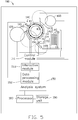
- FIG. 5 illustrates an automatic analysis device 100 of immunoassay analysis for analyzing a target component in a sample.
- the target component is defined as a component of the sample to be detected.
- the automatic analysis device 100 includes an incubation unit 110, a reagent holder 120, a reaction container supply 130, an operation mechanism 140, a cleaning separator 160, a sample supply depot 170, a processor 180, a storage unit 190, and an analysis system 150.
- the reagent holder 120 holds a number of reagent containers (not shown), such as a reagent bottle, and supplies different reagents during the analysis of the target component in the sample.
- the reaction container supply 130 receives a number of reaction containers 13, such as a cuvette, and supplies the reaction containers 13 to the incubation unit 110 during the analysis.
- the reaction container 13 holds a reactive solution.
- the reactive solution is acquired by agitating the sample successively with at least one reagent.
- the target component can be analyzed when the reactive solution has incubated for a predetermined time after the reagent is added to the sample.
- the reagent holder 120 and the reaction container supply 130 are located at a peripheral region of the incubation unit 110.
- the operation mechanism 140 includes a number of different apparatus to perform corresponding analysis operations in different periods of the immunoassay analysis.
- the operation mechanism 140 at least includes a detection unit 141, a delivering unit 146, a sample injection unit 144, and a reagent injection unit 145.
- the delivering unit 146 delivers the reaction container 13 between the incubation unit 110 and the other units located at the periphery of the incubation unit 110, such as the cleaning separator 160, the sample supply depot 170, and the reaction container supply 130.
- the delivering unit 146 includes a first delivering unit 142 and a second delivering unit 143.
- the first delivering unit 142 delivers the reaction container 13 among the incubation unit 110, the sample supply depot 170, and the reaction container supply 130.
- the second delivering unit 143 delivers the reaction containers 13 between the incubation unit 110 and the cleaning separator 160.
- the detection unit 141 detects the target component in the reactive solution.
- the detection unit 141 can be a photometer which detects luminous intensity of the target component and outputs an electric signal corresponding to the luminous intensity of the target component.
- a concentration of the target component in the sample can be calculated according to the luminous intensity.
- the sample injection unit 144 draws the sample and injects the sample to the reaction containers 13.
- the reagent injection unit 145 draws the reagents from the reagent containers and injects the reagents into the reaction containers 13.
- the sample injection unit 144 and the reagent injection unit 145 can be an aspirated needle. In other embodiments, the sample injection unit 144 and the reagent injection unit 145 can be combined as an injection unit (not shown).
- the incubation unit 110 provides a place to incubate the reactive solution held in the reaction container 13 and transport the reaction containers 13 to the operation mechanism 140.
- the incubation unit 110 can be a rotatable ring-shaped structure and includes at least one circular carousel.
- the incubation unit 110 includes at least one container holder 114 set on the circular carousel to hold the reaction container 13.
- the reaction containers 13 are held in the container holder 114.
- the incubation unit 110 transports the reaction containers 13 on the incubation unit 110 to different units 141-145 of the operation mechanism 140. In other embodiments, in view of temperature requirement to the incubation of the reactive solution, the incubation unit 110 still provides a constant temperature environment.
- a transport period of the incubation unit 110 includes at least one regular transport sub-period and at least one self-adaptive sub-period.
- the incubation unit 110 transports the reaction containers 13 a first transport distance in the regular transport sub-period.
- the incubation unit 110 transports the reaction containers 13 a second transport distance in the self-adaptive transport sub-period.
- the regular transport sub-period includes a regular transport duration and a regular stop duration.
- the self-adaptive transport sub-period includes a self-adaptive transport duration and a self-adaptive stop duration.
- the incubation unit 110 transports the reaction containers 13 in the regular transport duration and the self-adaptive transport duration.
- the incubation unit 110 remains stationary in the regular stop duration and the self-adaptive transport duration.
- the number of the regular transport sub-periods and the self-adaptive sub-periods in each transport period is determined according to the target component to be detected and a configuration of the automatic analysis device 100.
- the transport period can be two transports two stops type, which includes one regular transport sub-period and one self-adaptive sub-period.
- the transport period can be three transports and three stops type, which includes one regular transport sub-period and two self-adaptive sub-periods.
- the transport period also can be four transports and four stops type, which includes two regular transport sub-periods and two self-adaptive sub-periods.
- the incubation unit 110 defines at least one executing station R1, R2, R3, or R4 along a transport track of the container holders 114.
- a position coordinate system is defined to indicate a relative position of each executing station R1, R2, R3, or R4.
- the position coordinate of each executing station R1, R2, R3, or R4 is defined as a specific position on the transport track where the operation mechanism 140 performs the analysis operation to one of the container holders 114 of the incubation unit 110 when the incubation unit 110 remains stationary in the regular stop durations or self-adaptive stop durations.
- the different units 141-145 of the operation mechanism 140 are controlled to perform specific analysis operations to the reaction container 13 when the container holders 114 stop at the corresponding executing stations R1, R2, R3, or R4.
- the reaction container 13 during the incubation is transported on the incubation unit 110 and the different units 141-145 of the operation mechanism 140 not performing any analysis operations to the reaction container 13 during the incubation.
- the executing stations R1, R2, R3, or R4 at least include a detection station R1 where the detection unit 141 detects the target component in the reaction container 13, a reagent injection station R2 where the reagent injection unit 145 injects the reagent in the reaction container 13, a delivering station R3 where the second delivering unit 143 delivers the reaction containers 13, and a move-out station R4 where the first delivering unit 142 moves the reaction container 13 out of the incubation unit 110.
- the position coordinate of one executing station R1, R2, R3, or R4 can be an intersection of the container holder 114 and a movement track of the operation mechanism 140 or an intersection of the container holder 114 and a center line of the operation mechanism 140.
- the position coordinate of the reagent injection station R2 is the intersection of the container holder 114 and a movement track of the reagent injection unit 145.
- the position coordinate of the detection station R1 is the intersection of the container holder 114 and a center line of the operation mechanism.
- Each one of the executing stations R1, R2, R3, or R4 can correspond to more than one operation mechanism.
- the reagent injection station R2 can correspond to both the reagent injection unit 145 to perform the injection of reagent and the delivering unit 146 to perform the delivering operation of the reaction container 13.
- a transport interval M is defined between two regular resting positions of the same reaction container 13 on the incubation unit 110 corresponding in two adjacent regular stop durations.
- the transport interval M is a predetermined constant distance difference. That is, the same reaction container 13 on the incubation unit 110 sequentially stops at a number of regular resting positions located with the constant transport interval M corresponding in the successive regular stop durations.
- a transport step increment of the incubation unit 110 is defined as a minimum distance which the incubation unit 110 can transport. In this embodiment, the step increment of the incubation unit 110 is a separation distance between two adjacent container holders 114 on the incubation unit 110.
- each of the first transport distance, the second transport distance, and the transport interval M is calculated by an integral multiple of the separation distance between two adjacent container holders 114 on the incubation unit 110.
- the transport interval M means the transport interval is M multiples of the separation distance between two adjacent container holders 114 on the incubation unit 110.
- the transport interval M of the incubation unit 110 is preset as less than a total number N of the container holders 114 on the incubation unit 110 and cannot be exactly divided by the total number N of the container holders 114. Such that, each reaction container 13 on the incubation unit 110 passes by all the executing stations R1, R2, R3, or R4 when the incubation unit 110 has operated N regular transport sub-periods.
- the analysis operations performed to the reactive solution in the reaction containers 13 are classified as a number of regular operations and a number of self-adaptive operations.
- the regular operations are performed during the regular stop duration, for example, a move-in operation to move the reaction container 13 on the incubation unit 110 and a photometry operation to detect a luminous intensity of reactive solution, etc.
- the self-adaptive operations are performed during the self-adaptive stop duration. That is, the self-adaptive operations are performed after the reactive solution has been incubated for a flexible incubating duration.
- a move-out operation performed after the incubation of the reactive solution to move the reaction container 13 out of the incubation unit 110 and a second reagent injecting operation to add the second reagent in the reactive solution after the reactive solution has been incubated for the other flexible incubating duration.
- the incubation unit 110 transports the reaction containers 13 the second transport distance in the self-adaptive transport durations before performing the self-adaptive operation to the reactive solution in the reaction container 13.
- the second transport distance is variable based on a relative distance between a position of the executing station R1, R2, R3, or R4 performing the self-adaptive operation and a present position of the reaction container 13 to be performed the self-adaptive operation.
- the incubating duration is preset according to the target component in the sample to be detected.
- FIG. 5 illustrates the cleaning separator 160 is located outside of the incubation unit 110, that is the cleaning separator 160 and the incubation unit 110 are independent from each other.
- the sample supply depot 170 provides a place to hold the reaction container 13 ready for the injection of the sample.
- the sample supply depot 170 also can be set on the incubation unit 110.
- the analysis system 150 includes a control module 151, a data processing module 152, and an interactive module 153.
- One or more programs of the function modules of the analysis system 150 can be stored in the storage unit 190 and executed by the processor 180.
- the processor 180 can be a central processing unit, a digital processor, or a single chip, for example.
- the storage unit 190 can be a hard disk, a compact disk, or a flash memory, for example.
- the control module 151 is respectively connected to the incubation unit 110, the reagent holder 120, the cleaning separator 160, the sample injection unit 144, the reagent injection unit 145, the first delivering unit 142, and the second delivering unit 143 to control the analysis operations.
- the control module 151 is connected to the interactive module 153 to receive input information of the user.
- the data processing module 152 is connected to the detection unit 141 to receive the electric signal output from the detection unit 141.
- the data processing module 152 processes the electric signal and outputs a result of the process to the user via the interactive module 153.
- the control module 150 is connected to the detection unit 141 to control the analysis operation of the detection unit 141.
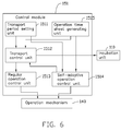
- FIG. 6 illustrates the control module 151 includes a transport period setting unit 1511, a transport control unit 1512, a regular operation control unit 1513, and a self-adaptive operation control unit 1514.
- the transport period setting unit 1511 sets the transport periods according to the target component and the test mode of the analysis.
- the transport control unit 1512 controls the incubation unit 110 to transport according to the transport periods set by the transport periods setting unit 1511. In the regular transport sub-period, the transport control unit 1512 controls the incubation unit 110 to transport the reaction containers 13 the first transport distance during the regular transport duration and the reaction container 13 remains stationary at the executing stations R1, R2, R3, or R4 corresponding to the regular operations in the regular stop duration.
- the transport control unit 1512 controls the incubation unit 110 to transport the reaction containers 13 the second transport distance during the self-adaptive transport duration and then the reaction containers 13 remain stationary at the executing stations R1, R2, R3, or R4 corresponding to the self-adaptive operations in the self-adaptive stop duration.
- the regular operation control unit 1513 controls the operation mechanism 140 to perform the corresponding regular operations to the reaction containers 13 in the regular stop duration.
- the self-adaptive operation control unit 1514 controls the operation mechanism 140 to perform the corresponding self-adaptive operations to the reaction containers 13 during the self-adaptive stop duration.
- the first transport distance is calculated by the transport control unit 1512 according to the present position of the reaction containers 13 and a number of regular resting positions of the reaction containers 13.
- the regular resting positions are defined as a number of positions where the reaction containers 13 on the incubation unit 110 remain stationary in each of the regular stop durations.
- the regular resting position of the reaction container 13 in the regular stop duration of the forthcoming regular transport sub-period is calculated by the regular resting position of the reaction container 13 in the regular stop duration of the last regular transport sub-period added with the transport interval M.
- the first transport distance is calculated as a distance difference between the present position of the reaction container 13 and the regular resting position of the reaction container 13 in the regular stop duration of the forthcoming regular transport sub-period.
- the second transport distance is calculated as a distance difference between a present position of the reaction container 13 and the position coordinate of the executing station R1, R2, R3, or R4 where the self-adaptive operation is performed.
- the regular operations and the self-adaptive operations performed to the reaction container 13 are determined according to the target component received in the reaction container 13.
- the user inputs the name of the target component and all the analysis operations needed to detect the target component via the interactive module 153.
- the test modes used to detect the target component such as the one step test mode or the two steps test mode, is determined by all the analysis operations corresponding to the target component.
- control module 151 further includes an operation time sheet generating unit 1515.
- the operation time sheet generating unit 1515 generates an operation time sheet of a corresponding relation between a chronological sequence of the analysis operations and the transport period of the incubation unit 110 according to the target components, the analysis operations, and test modes input by the user.
- the operation time sheet can be generated before the start of the target component analysis or after the input of the analysis operations, also can be generated during the target component analysis.
- the control module 151 reads the operation time sheet to determine which analysis operation is performed by checking whether or not the chronological sequence of the analysis operations for one of the reaction containers 130 match with the transport period of this reaction container 130 on the incubation unit 110, for example, if a performing time of one specific regular operation for one reaction container 13 matches with the regular transport sub-period of the reaction container 13, the regular operation control unit 1513 controls the operation mechanism 140 to perform the specific regular operation to the reaction container 13 in the regular stop duration matching with the specific regular operation.
- the self-adaptive operation control unit 1514 controls the operation mechanism 140 to perform the specific self-adaptive operation to the reaction container 13 in the self-adaptive stop duration matching with the specific self-adaptive operation.
- the first transport distance can be calculated before the regular transport duration or immediately after the operation time sheet has been generated.
- the second transport distance can be calculated before the self-adaptive transport duration or immediately after the operation time sheet has been generated.
- the reactive solution having different incubating durations can be timely performed by the self-adaptive operation.
- the sequence of the regular resting positions of the reaction containers 13 is not disturbed by the self-adaptive transport of the incubation unit 110.
- the regular operations can be orderly performed to the reaction containers 13 at the same time.
- the analysis efficiency for the target component having different incubating durations is improved.
- the incubation unit 210 includes two rounds of container holders 214 defined on the circular carousel.
- the incubation unit 210 can hold more reaction containers 13.
- the reaction containers 13 on different rounds can concurrently perform the regular operations and serially perform the self-adaptive operations.
- the automatic analysis device 100 using the incubation unit 210 can be flexible to more different immunoassay analysis with specific analysis operation. The test flux of the automatic analysis device 100 is increased. It is understood that the incubation unit 210 includes more than two rounds of container holders 214 defined on the carousel.
- FIG. 8 illustrates the incubation unit 310 includes three surrounding independently driven ring-shaped carousels. Each carousel is substantially rectangular. Because the reaction containers 13 on different carousels can be independently driven in different directions. The reaction containers 13 corresponding to different transport periods can be analyzed at the same time, the efficiency of the automatic analysis device 100 is improved.
- the present embodiment is further illustrated as below in combination with a specific transport period.
- FIG. 9 illustrates in the embodiment, the regular photometry operation is performed at the detection station R1.
- the regular move-in operation is performed at a move-in station R2.
- the self-adaptive second reagent injecting operation and the self-adaptive move-out operation are performed at the delivering station R3.
- the regular move-out operation is performed at the move-out station R4.
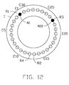
- the total number N of the container holders 114 is thirty.
- the position coordinates C1, C2... C30 of the executing stations R1, R2, R3, or R4 is defined along a counterclockwise direction from an original point C1 at the detection station R1.
- the position coordinate of the move-out station R4 is C12.
- the position coordinate of the move-in station R2 is C13.
- the position coordinate of the delivering station R3 is C23.
- the container holders 114 are numbered as N1, N2, N3 ... and N30 along a clockwise direction beginning from an original point N1 which is the container holder 114 at the executing station R1
- the analysis operations of the one step and one separation test mode includes a sample injecting operation, a reagent injecting operation, the regular move-in operation moving a new reaction container 13 on the incubation unit 110, the self-adaptive move-out operation moving the reaction container 13 to the cleaning separator 160 after the incubation, the regular move-in operation moves the reaction container 13 back on the incubation unit 110 after the separation of unreacted components, and the photometry operation.
- FIG. 10 illustrates a sequence chart of the Tn transport period.
- the transport period includes one regular transport sub-period and one self-adaptive transport sub-period. That is the incubation unit 110 transports twice and stops twice in one transport period.
- the regular transport sub-period includes a regular transport duration SC and a regular stop duration ST.
- the self-adaptive transport sub-period includes a self-adaptive transport duration AC and a self-adaptive stop duration AT.
- the self-adaptive move-out operation moves the reaction container 13 to the cleaning separator 160 after the incubation is performed during the self-adaptive stop duration.
- FIG. 13 a flowchart is illustrated in accordance with an embodiment of a component analysis method of the automatic analysis device 100.
- the component analysis method is provided by way of example, as there are a variety of ways to carry out the method.
- the component analysis method described below can be carried out using the configurations illustrated in FIGS. 5 , 7, and 8 , for example, and various elements of these figures are referenced in explaining example method.
- Each blocks shown in FIGS. 13 , 14 , 15 , and 16 represents one or more processes, methods or blocks is by example only and order of the blocks can change according to the present disclosure.
- the embodiment of the component analysis method can begin at block 200.
- the operation time sheet is generated according to the target component and the analysis operations input by the user.
- the operation time sheet records the chronological sequence of the analysis operations for each reaction container 13 on the incubation unit 110, the transport period of the incubation unit 110, and the corresponding relation therebetween.
- the chronological sequence of the analysis operations is cooperatively determined by a start time of the analysis, a serial number of the reaction container 13, the analysis operations performed to the reaction container 13, and the transport periods of the incubation unit 110.
- the transport period includes at least one regular transport sub-period and at least one self-adaptive transport sub-period.
- the incubation unit 110 is transported the first transport distance in the regular transport sub-period.
- the incubation unit 110 is transported the second transport distance in the self-adaptive sub-period.
- the first transport distance is calculated when the incubation unit 110 is ready to run in the forthcoming regular transport sub-period.
- the first transport distance is calculated as a distance difference between the present position of the reaction container 13 and the regular resting position of the reaction container 13 in the forthcoming regular stop duration.
- the regular resting position of the reaction container 13 in the forthcoming stop duration is calculated by adding the regular resting position of the reaction container 13 in the last stop duration with the transport interval M.
- the transport interval M is a predetermined constant distance difference defined between two regular resting positions of the same reaction container 13 on the incubation unit 110 corresponding in two adjacent regular stop durations.
- the transport interval M is an integral multiple of the step increment of the incubation unit 110.
- the step increment of the incubation unit 110 is defined as a minimum distance which the incubation unit 110 can transport. In this embodiment, the step increment of the incubation unit 110 is a separation distance between two adjacent container holders 114 on the incubation unit 110.
- the specific regular operation performed during the forthcoming regular stop duration is determined before the incubation unit 110 stops.
- the specific regular analysis operation is determined by checking the operation time sheet to find which chronological sequence matches with the stop duration of the forthcoming regular transport sub-period.
- the incubation unit 110 transports the reaction container 13 the first transport distance in the regular transport duration. And then, the reaction container 13 is transported to the regular resting position of the present regular stop duration.
- the specific regular operation is performed to the reaction container 13 at the regular resting position of the present regular stop duration.
- reaction container 13 remains stationary without any operation being performed if there is no regular operation matching with this present regular transport period.
- the second transport distance is calculated if there is the chronological sequence of the specific self-adaptive operation matching with the forthcoming self-adaptive stop duration.
- the second transport distance is calculated as a distance difference between a present position of the reaction container 13 to be performed by the specific self-adaptive operation and the position coordinate of the executing station R1, R2, R3, or R4 where the specific self-adaptive operation is performed.
- the incubation unit 110 transports the reaction container 13 the second transport distance in the self-adaptive transport duration, and then the reaction container 13 is transported to the position coordinate of the executing station R1, R2, R3, or R4 where the specific self-adaptive operation is performed.
- the specific self-adaptive operation is performed to the reaction container 13 in the present self-adaptive stop duration.
- the incubation unit 110 remains stationary in the forthcoming self-adaptive transport sub-period. In other embodiments, the incubation unit 110 can be transported a predetermined distance in this self-adaptive transport sub-period without performing the self-adaptive operation.
- the blocks 202, 203, 205, 206 can be carried out as long as the operation time sheet and the transport period of the incubation unit 110 have been determined, such as during the transporting of the incubation unit 110 or before the transporting of the incubation unit 110.
- the regular operation control unit 1513 checks the operation time sheet to find out the chronological sequence of the regular operation reaction matching with the regular stop duration ST.
- the transport control unit 1512 controls the incubation unit 110 to transport the reaction container 13 held in the container holder 114 with a serial number N1 the first transport distance during the regular transport duration SC.
- the positions of the reaction containers 13 on the incubation unit 110 after the regular transport duration SC of the Tn regular transport sub-period are illustrated in FIG. 9 .
- the container holders 114 with the serial number N1 and the container holders 114 with the serial number N19 are correspondingly transported to the detection station R1 and the move-in station R2.
- the detection unit 141 performs the photometry operation to the reaction container 13 held in the container holder 114 with the serial number N1.
- the first delivering unit 142 performs the move-in operation to deliver a new reaction container 13 in the container holder 114 with the serial number N19.
- the regular operation control unit 1513 controls the reagent injection unit 145 to inject the reagent in the reaction container 13 held in the container holder 114 with the serial number N19.
- the incubation unit 110 runs the self-adaptive transport sub-period of the Tn transport period after the operations in the regular stop duration have been finished.
- the self-adaptive operation control unit 1514 checks the operation time sheet to find whether or not the chronological sequence of the self-adaptive operation matches with the self-adaptive stop duration AT. If there is at least one self-adaptive operation matching with the self-adaptive stop duration AT, the transport control unit 1512 calculates the second transport distance Xn according to the present position of the reaction containers 13 and the position coordinate of the executing station R1, R2, R3, or R4 performing the self-adaptive operation.
- the second transport distance Xn is an integer multiple of the step increment of the incubation unit 110.
- the second transport distance Xn can be zero or less than the total number N of the container holders 114 on the incubation unit 110.
- a counterclockwise direction is defined as a positive direction of the second transport distance.
- the second transport distance Xn is zero, which means that the incubation unit 110 remains stationary in the self-adaptive transport duration AC or transport N multiples of the step increment of the incubation unit 110.
- the transport control unit 1512 controls the incubation unit 110 to transport the reaction container 13 the second transport distance Xn during the self-adaptive transport duration AC, and then the reaction container 13 which needs the self-adaptive operation performed arrives at the executing station R1, R2, R3, or R4.
- the self-adaptive operation control unit 1514 controls the second delivering unit 143 to move the reaction container 13 to the cleaning separator 160.
- a move-in operation for moving a new reaction container 13 on the incubation unit 110 is performed during each regular transport sub-period. That means a new analysis is activated in each transport period.
- the first regular transport sub-period only the move-in operation is performed to move a new reaction container 13 in the container holder 114 located at the move-in station R2.
- the reaction container 13 moved on the incubation unit 110 during the regular stop duration ST is different from the reaction container 13 moved out of the incubation unit 110 during the self-adaptive stop duration AT.
- the first transport distance of the incubation unit 110 in the T(n+1) transport period is calculated as (M-Xn) with the counterclockwise direction as the positive direction.
- the incubation unit 110 transports the reaction container 13 in the clockwise direction if (M-Xn) is less than zero.
- the incubation unit 110 remains stationary if (M-Xn) is zero.
- Xn presents the second transport distance of the incubation unit 110 in the Tn transport period.
- the transport interval M presents the transport interval which is a relative distance between the regular resting position of the reaction container 13 in the regular stop duration of the Tn regular transport sub-period and the regular resting position of the reaction container 13 in the regular stop duration of the T(n+1) regular transport sub-period. That is, comparing with the Tn regular transport sub-period, the incubation unit 110 transports forward or backwards a constant distance difference M after the T(n+1) regular transport sub-period.
- the transport interval M is 7, the container holder 114 with the serial number N8 and the container holder 114 with the serial number N27 are correspondingly located at the executing stations R1 and R4 after the Tn+1 transport period.
- the reaction containers 13 held in the container holders 114 with the serial numbers N8 and N27 can simultaneously perform the corresponding regular operations. If the incubation of the reaction container 13 held in the container holder 114 with the serial number N10 is finished in Tn+1 transport period and needs to perform the self-adaptive move-out operation, the transport control unit 1512 calculates the second transport distance Xn+1 of the Tn+1 self-adaptive transport sub-period according to the present position of the container holder 114 with the serial number N10 and the position coordinate of the delivering station R3 where the self-adaptive move-out operation is performed. In this embodiment, the second transport distance Xn+1 is twenty four which means the container holder 114 with the serial number N10 is to be transported along the counterclockwise twenty four step increments. The transport control unit 1512 controls the incubation unit 110 to transport the container holder 114 with the serial number N10 the second transport distance Xn+1.
- FIG. 12 illustrates the reaction container 13 held in the container holder 114 with the serial number N10 is transported to the delivering station R3.
- the self-adaptive operation control unit 1514 controls the second delivering unit 143 to move the reaction container 13 held in the container holder 114 with the serial number N10 to the cleaning separator 160.
- the setting of the regular transport sub-period of the incubation unit 110 can make sure every reaction container 13 on the incubation unit 110 is transported to pass by all the executing stations R1, R2, R3, or R4 after N transport periods and performs the corresponding regular operations.
- the setting of the self-adaptive transport sub-period of the incubation unit 110 can make the reaction container 13 be transported to any of the executing stations R1, R2, R3, or R4 as soon as possible after the incubation.
- the automatic analysis device 100 employing the regular transport sub-period and the self-adaptive transport sub-period is suitable for a flexible combination of the target component analyses having different incubation times
- FIG. 14 illustrates a flowchart of a component analysis method for the target component in accordance with the one step and one separation test mode
- FIGS. 5 and 10 illustrate the embodiment of the component analysis method can begin at block 1000.
- the sample is injected in the reaction container 13.
- the first delivering unit 142 transports a new empty reaction container 13 from the reaction container supply 130 to the sample supply depot 170.
- the sample injection unit 144 injects the sample in the reaction container 13 held in the sample supply depot 170.
- the incubation unit 110 performs the regular transport to move one empty container holder 114 to the reagent injection station R2.
- the first delivering unit 142 performs the regular move-in operation to move the reaction container 13 filled with the sample in the container holder 114 to the incubation unit 110.
- the reagent injection unit 145 is concurrently controlled to draw the reagent when the reaction container 13 is moved to the incubation unit 110.
- the reagent injection unit 145 is controlled to inject the reagent to the reaction container 13.
- the first delivering unit 142 and the reagent injection unit 145 perform the corresponding regular operations in the regular stop duration ST and the efficiency of the analysis is improved.
- the reaction container 13 is incubated on the incubation unit 110.
- the incubation time for the reaction container 13 is set according to the target component to be analyzed and recorded in the operation time sheet.
- the incubation unit 110 performs a self-adaptive transport in the forthcoming self-adaptive transport duration AC when the incubation of the reaction container 13 is finished.
- the second transport distance X of this self-adaptive transport is calculated according to the present position of the reaction container 13 and the position coordinate of the delivering station R3 where the self-adaptive move-out operation is performed.
- the reaction container 13 is transported to the delivering station R3.
- the second delivering unit 143 performs the self-adaptive move-out operation moving the reaction container 13 from the incubation unit 110 to the cleaning separator 160. In the next few transport periods, the separation of the unreacted component is performed during the reaction container 13 by the cleaning separator 160.
- the reaction container 13 is moved back on the incubation unit 110 after the separation of the unreacted component.
- the reaction container 13 awaits the incubation unit 110 to transport a new empty container holder 114 to the delivering station R3 via the regular transport. And then, the reaction container 13 is moved back in the empty container holder 114 on the incubation unit 110.
- the reaction container 13 is transported to the detection station R1. If the reactive solution in the reaction container 13 does not need the second incubation for the illumination, the incubation unit 110 transports the reaction container 13 to the detection station R1 via a few regular transports. If the reactive solution in the reaction container 13 needs the second incubation for illumination, the incubation unit 110 transports the reaction container 13 to the detection station R1 via the self-adaptive transport after the second incubation for illumination.
- the detection unit 141 performs the regular photometry operation to detect the illumination of the reaction container 13.
- the reaction container 13 is moved out of the incubation unit 110 after the photometry operation.
- the reaction container 13 is transported to the move-out station R4 after the photometry operation.
- the first delivering unit 142 is controlled to move the reaction container 13 out of the incubation unit 110.
- the sample injection is performed outside the incubation unit 110. It is understood that the reagent injection also can be performed outside the incubation unit 110.
- FIG. 15 illustrates at block 1100, the sample and the reagent are injected in the reaction container 13 outside the incubation unit 110.
- the incubation unit 110 performs the regular transport to move one empty container holder 114 to the reagent injection station R2.
- the first delivering unit 142 performs the regular move-in operation to move the reaction container 13 filled with the sample and the reagent in the container holder 114 on the incubation unit 110.
- the reaction container 13 is incubated on the incubation unit 110.
- the incubation time for the reaction container 13 is set according to the target component to be analyzed and recorded in the operation time sheet.
- the incubation unit 110 performs a self-adaptive transport in the forthcoming self-adaptive transport duration AC when the incubation of the reaction container 13 is finished.
- the reaction container 13 is transported to the delivering station R3.
- the second delivering unit 143 performs the self-adaptive move-out operation to move the reaction container 13 from the incubation unit 110 to the cleaning separator 160.
- the detection unit 141 performs the photometry operation to detect the illumination of the reaction container 13 on the cleaning separator 160.
- the operation of the incubation unit 110 is simplified.
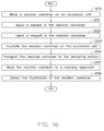
- FIG. 16 illustrates at block 1200, in the regular stop duration SC, the first delivering unit 142 performs the regular move-in operation to move the reaction container 13 in the container holder 114 on the incubation unit 110.
- the sample injection unit 144 is controlled to inject the sample in the reaction container 13 on the incubation unit 110.
- the reagent injection unit 145 is controlled to inject the reagent to the reaction container 13.
- the block 1201 and the block 1202 also can be successively carried out in the regular stop duration ST.
- the reaction container 13 is incubated on the incubation unit 110.
- the incubation time for the reaction container 13 is set according to the target component to be analyzed and recorded in the operation time sheet.
- the incubation unit 110 performs a self-adaptive transport in the forthcoming self-adaptive transport duration AC when the incubation of the reaction container 13 is finished.
- the reaction container 13 is transported to the delivering station R3.
- the second delivering unit 143 performs the self-adaptive move-out operation to move the reaction container 13 from the incubation unit 110 to the cleaning separator 160.
- the detection unit 141 performs the photometry operation to detect the illumination of the reaction container 13 on the cleaning separator 160.
- the operation of the delivering unit 146 is simplified.
- FIGS. 14 , 15 , and 16 are different from each other, but are suitable for the same transport period setting. The difference therebetween refers to the different regular operations.
- Each executing station R1, R2, R3, or R4 can perform only one analysis operation or a number of different analysis operations, even one executing station R1, R2, R3, or R4 can perform both of the regular operation and the self-adaptive operation, for example, a move-in or out station is defined to perform both regular move-in operations and the self-adaptive move-out operations.
- the operation of one executing station R1, R2, R3, or R4 can be performed by one kind of the operation mechanism 140 or different kinds of the operation mechanisms 140, for example, in the injection unit, the sample injection and the reagent injection can be performed by the same aspirating needle or correspondingly be the sample injection needle and the reagent injection needle.
- the analysis design is more flexible.
- the number of executing stations R1, R2, R3, or R4 and the function of each station can be set according to a balance of the size of the automatic device, the cost of the manufacturing, and the test flux requirement of the component analysis.
- an agitating operation can be added as a regular operation or a self-adaptive operation after the sample and reagent injection.
- the agitating operation agitates the sample with the reagent in the reaction container 13.
- FIG. 3 illustrates the analysis operations in accordance with the two steps and one separation test mode includes the sample injecting operation, the move-in operation, a first reagent injecting operation, a second reagent injecting operation, the move-out operation, and the photometry operation. Because the times for the first incubation after the sample and the first reagent injection and the second incubation after the second reagent injection is determined according to the target component to be analyzed, the second reagent injecting operation after the first incubation and the move-out operation after the second incubation are defined as the self-adaptive operations.
- a difference between a component analysis method in accordance with the two steps and one separation test mode and the component analysis method in accordance with the one step and one separation test mode is the component analysis method in accordance with the two steps and one separation test mode further includes a second self-adaptive transport after the first incubation and a second self-adaptive operation to inject the second reagent between the first incubation for the sample and the first reagent of block 1003 and the self-adaptive transport ready for the move-out operation of block 1004.
- the first incubation is performed during the reaction container 13.
- the reaction container 13 is self-adaptive transported to the reagent injection station R2 when the first incubation is finished.
- the self-adaptive second reagent injecting operation is performed to the reaction container 13 after the reaction container 13 has been transported to the reagent injection station R2.
- the second incubation is performed on the reaction container 13.
- the reaction container 13 is self-adaptive transported to the delivering station R3 when the second incubation is finished, and then, the second delivering unit 143 performs the self-adaptive move-out operation to move the reaction container 13 from the incubation unit 110 to the cleaning separator 160.
- the rest analysis flow of the component analysis method for the two steps and one separation test mode is similar with that of the component analysis method in accordance with the one step and one separation test mode.
- FIG. 4 illustrates the analysis operations in accordance with the two steps and two separations test mode includes the sample injecting operation, the first move-in operation, the first reagent injecting operation, the first move-out operation, the second move-in operation, the second reagent injecting operation, the second move-out operation, and the photometry operation. Because the times for the first incubation of the sample and after the first reagent injection and the second incubation, the second reagent injection is determined according to the target component to be analyzed, the first move-out operation, the first incubation and the second move-out operation after the second incubation are the self-adaptive operations.
- a difference between a component analysis method for the two steps and two separations test mode and the component analysis method in accordance with the one step and one separation test mode is the component analysis method in accordance with the two steps and two separations test mode further includes a second move-in operation to move the reaction container 13 on the incubation unit 110 after the first separation, a second self-adaptive transport transporting the reaction container 13 to the delivering station R3 after the second incubation, and a second self-adaptive operation moving the reaction container 13 out of the incubation unit 110 after the second incubation between the first separation of the unreacted sample and the first reagent of block 1005 and the move-in operation moving the reaction container 13 back on the incubation unit 110 of block 1006.
- the first incubation is performed on the reaction container 13.
- the reaction container 13 is self-adaptive transported to the delivering station R3 when the first incubation is finished.
- the self-adaptive first move-out operation is performed to the reaction container 13 moving the reaction container 13 to the cleaning separator 160 for the first separation.
- the reaction container 13 is moved back on the incubation unit 110 after the first separation.
- the second reagent injection is performed on the reaction container 13 after the reaction container 13 has been transported to the reagent injection station R2.
- the second incubation is performed on the reaction container 13.
- the reaction container 13 is self-adaptive transported to the delivering station R3 when the second incubation is finished, and then, the self-adaptive second move-out operation is performed by the second delivering unit 143 moving the reaction container 13 from the incubation unit 110 to the cleaning separator 160.
- the rest analysis flow of the component analysis method for the two steps and two separations test mode is similar with that of the component analysis method for the one step and one separation test mode.
- the transport periods in accordance with the two steps and one/two separations test mode includes at least two self-adaptive transport sub-periods for correspondingly performing the two self-adaptive operations, for example, FIG. 17 illustrates the Tn transport period includes a first regular transport sub-period, a first self-adaptive transport sub-period, a second regular transport sub-period, and a second self-adaptive transport sub-period.
- the first regular transport sub-period includes a first regular transport duration SC1 and a first regular stop duration ST1.
- the first self-adaptive transport sub-period includes a first self-adaptive transport duration AC1 and a first self-adaptive stop duration AT1.
- the second regular transport sub-period includes a second regular transport duration SC2 and a second regular stop duration ST2.
- the second self-adaptive transport sub-period includes a second self-adaptive transport duration AC1 and a second self-adaptive stop duration AT1.
- FIG. 18 illustrates the Tn transport period also can include only one regular transport sub-period, a first self-adaptive transport sub-period, and a second self-adaptive transport sub-period.
- the regular transport sub-period includes a regular transport duration SC and a regular stop duration ST.
- the first self-adaptive transport sub-period includes a first self-adaptive transport duration AC1 and a first self-adaptive stop duration AT1.
- the second self-adaptive transport sub-period includes a second self-adaptive transport duration AC1 and a second self-adaptive stop duration AT1.
- the component analysis method also can include other analysis operations except the analysis operations mentioned above for satisfying a pre-treatment, a sample pre-dilution, three-steps test mode, and a combination thereof.
- the automatic analysis device 100 can concurrently run more analysis operations in the regular transport sub-period and serially run more self-adaptive analysis operations in the self-adaptive transport sub-period.
- the component analysis becomes more flexible and the efficiency of the analysis is improved.
- a difference between the first embodiment and the second embodiment is the determination of the first transport distance.
- the first transport distance F is a predetermined constant distance difference. That is, the incubation unit 110 transports a predetermined constant distance along the predetermined direction in each of the regular transport durations.
- the first transport distance F is an integral multiple of the separation distance between two adjacent container holders 114 on the incubation unit 110.
- the first transport distance F is less than the total number N of the container holders 114 on the incubation unit 110 and cannot be exactly divided by the total number N of the container holders 114.
- the incubation unit 110 is controlled to return to the regular resting position of the last regular transport sub-period, after the present self-adaptive operation is finished.
- the container holders 114 also can be transported to pass by all executing stations R1, R2, R3, or R4 in N transport periods.
Landscapes
- Chemical & Material Sciences (AREA)
- Physics & Mathematics (AREA)
- Health & Medical Sciences (AREA)
- Life Sciences & Earth Sciences (AREA)
- Analytical Chemistry (AREA)
- Biochemistry (AREA)
- General Health & Medical Sciences (AREA)
- General Physics & Mathematics (AREA)
- Immunology (AREA)
- Pathology (AREA)
- Chemical Kinetics & Catalysis (AREA)
- Automatic Analysis And Handling Materials Therefor (AREA)
Description
- This application is a continuation under 35 U.S.C. §120 of international patent application No.
PCT/CN2013/083960, filed on September 23, 2013 201310132098.1, filed on April 11, 2013 - The subject matter herein generally relates to medical technologies, and particularly, to a component analysis method, a component analysis system, and an automatic analysis device using same.
- A luminescence immunoassay is a major technology used in a clinical immunoassay analysis. Take one step sandwich method as example, main principles of the luminescence immunoassay include following steps.
Step 1, a number of reagents corresponding to a target component is prepared in a sample. The target component is defined as a component of the sample to be detected. The reagents can be a magnetic bead reagent and a labeling reagent. The magnetic bead reagent is composed of a number of magnetic beads coated by antibodies/antigens corresponding to the target component. The labeling reagent is composed of antibodies labeled by a specified mark. The different reagents are correspondingly received in a number of different reagent containers or a number of different cavities in a same reagent container. Step 2, a reactive solution of the sample and the reagent are acquired by agitating the sample successively with the reagents. A reactive complex is formed in the reactive solution by an incubation reaction under determined conditions. Step 3, the other components of the sample and the reagents not reacting in the reactive solution is removed by use of a Bound-free technology (B/F). Step 4, a signal reagent is added in the reactive solution. The signal reagent reacts with the specified mark on the reactive complex to illuminate. - A luminescence immunity analyzer usually employs the following conventional test modes corresponding to different characters of immunoreactions mode of the target component.
-
FIG. 1 illustrates the one step and one separation test mode, which is the simplest test mode, means the test only needs to employ one kind of reagent. The sample and the reagent are filled in a reaction container to form the reactive solution. The reactive solution is agitated and takes the incubation reaction for a first predetermined duration in a first stationary temperature. And then, the other components of the sample and the rest of the reagents not reacting in the reactive solution is separated from the reactive solution and removed by use of the bound-free technology. Finally, the signal reagent is filled in the reactive solution to incubate for a second predetermined duration in a second stationary temperature and then illuminated. The illumination of the reactive solution is measured to detect the target component.FIG. 2 illustrates the other test mode; the illumination of the reactive solution can be measured directly without incubation. For example, the test mode based on electrochemical luminescence or flash type chemical luminescence. -
FIG. 3 illustrates the sample and a first reagent are filled in the reaction container and agitated to form the reactive solution. The reactive solution takes the first incubation reaction for the first predetermined duration in the first stationary temperature. And then, a second reagent is filled in the reaction container and agitated with the reactive solution. The reactive solution takes a second incubation reaction for the second predetermined duration in the second stationary temperature. The other components of the sample, the rest of the first reagent, and the rest of the second reagent not reacting in the reactive solution is separated from the reactive solution and removed after the second incubation reaction. Thereafter, the signal reagent is filled in the reactive solution to incubate for a third predetermined duration in a third stationary temperature, and then the reactive solution illuminate. The illumination of the reactive solution is measured to detect the target component. As mentioned above, in the other test mode, the illumination of the reactive solution can be measured directly with no incubation. -
FIG. 4 illustrates the sample and the first reagent are filled in the reaction container and agitated to form the reactive solution. The reactive solution takes the first incubation reaction for the first predetermined duration in the first stationary temperature and then the other component of the sample and the rest of the first reagent not reacting in the reactive solution is separated from the reactive solution and removed. Later, the second reagent is filled in the reaction container and agitated with the reactive solution. The reactive solution takes the second incubation reaction for the second predetermined duration in the second stationary temperature. The rest of the second reagents not reacting in the reactive solution is separated from the reactive solution and removed after the second incubation reaction. Thereafter, the signal reagent is filled in the reactive solution after the separation to incubate a third predetermined duration in a third stationary temperature and then illuminated. The illumination of the reactive solution is measured to detect the target component. As mentioned above, in the other test mode, the illumination of the reactive solution can be measured directly without incubation. - Other steps besides the conventional test steps mentioned above are not listed in the description, for example, a sample pre-treatment step, a sample pre-dilution step, and three-step measurement.
- The luminescence immunity analyzer can be classified as single mode and multi-modes according to a flexibility of the incubating duration and the test steps. The single mode luminescence immunity analyzer transports the reaction container to different executing stations via a fixed transport of an incubation unit. The fixed transport means that a transport distance or a step increment of the incubation unit in each periodic time period is invariable and does not change with the predetermined incubating duration. Thus, the single mode luminescence immunity analyzer is only available for a fixed combination of several test steps and several kinds of invariable incubations, for example, the one step and one separation test mode or two steps and two separations test mode. The incubation duration can be several different time periods or an integral multiple of a fixed time period, such as 15 minutes, 30 minutes, or 45 minutes etc. The multi-modes luminescence immunity analyzer can be available for flexible combinations of several test steps and variable incubating duration. For example, the flexible combinations of the extraordinary test steps and the conventional test steps. The incubating duration setting can be adjusted from several seconds to a few minutes, such as 15 seconds, 6 minutes, 10.5 minutes, 60 minutes, etc. The multi-modes luminescence immunity analyzer can adjust the test steps and the incubating duration according to the target component, which is more convenient than the single mode luminescence immunity analyzer.
- The incubating duration depends on the target component. In use, the multi-modes luminescence immunity analyzer transports the reaction container to different executing stations via a self-adaptive transport of the incubation unit. The self-adaptive transport means that the transport distance or a step increment of the incubation unit in each periodic time period can be varied with the target component. The executing stations may include, but are not limited to, a sample injection station, a reagent injection station, a reaction container move in station, a reaction container move out station, and a detecting station. The executing stations are located along a transport track of the reaction container in predetermined interval to perform specific operation to the reaction container. In multi-sample analysis, when the incubation unit transports a target reaction container to the specific executing station via the self-adaptive transport, the other reaction containers may not arrive at the executing stations which can perform appropriate operation. The other reaction containers cannot be treated by the executing stations simultaneously with the target reaction container. Such that, the incubation unit needs a lot of self-adaptive transports to deliver the reaction container to accomplish a serial of operations performed by the different executing stations. The inefficiency of this serial fashion test mode adversely limits a test flux of the luminescence immunity analyzer.
- The main technical problem to be solved by the present disclosure is to provide a component analysis method, a component analysis system, and an automatic analysis device using the method and system to concurrently perform a number of analysis operations and satisfy different incubation time requirements. Thus, the analysis capability and the test flux of the automatic analysis device are improved.
- A first aspect of this application is a component analysis method of an automatic analysis device. The automatic analysis device includes an incubation unit that holds at least one reaction container which contains a sample and a number of executing stations set around the incubation unit to correspondingly perform a number of analysis operations to the reaction container.
- The component analysis method includes, setting a transport period of the incubation unit and a chronological sequence of the analysis operations according to a target component to be analyzed out from the sample, wherein the transport period includes at least one regular transport sub-period and at least one self-adaptive transport sub-period and the analysis operations include a number of regular operations and a number of self-adaptive operations.
- Controlling the incubation unit to transport the reaction container a first transport distance during the regular transport sub-period, wherein the reaction container is transported to one of the number of executing stations, where the reaction container is performed the regular operation in the regular transport sub-period.
- Performing at least one of the regular operations to the reaction container if the chronological sequence of the regular operation matches the regular transport sub-period.
- Controlling the incubation unit to transport the reaction container a second transport distance during the self-adaptive transport period, wherein the reaction container is transported to another one of the number of executing stations, where the reaction container is performed the self-adaptive operation in the self-adaptive transport sub-period.
- Then, performing at least one of the self-adaptive operations to the reaction container if the chronological sequence of the self-adaptive operation matches the self-adaptive transport sub-period.
- The first transport distance is calculated as a distance difference between a present position of the reaction container and a regular resting position of the reaction container in the forthcoming regular transport period. The regular resting position of the reaction container in the forthcoming regular transport period is calculated by adding a regular resting position of the reaction container in the last regular transport period with a transport interval. The transport interval is a predetermined constant distance difference defined between two regular resting positions of the same reaction container in two adjacent regular transport periods. The second transport distance is calculated as a distance difference between the present position of the reaction container and a position of the executing station where the self-adaptive operation is performed during the forthcoming self-adaptive transport period.
- Another component analysis method of an automatic analysis device is provided. The automatic analysis device includes an incubation unit that holds at least one reaction container which contains a sample and a number of executing stations set around the incubation unit to correspondingly perform a number of analysis operations to the reaction container.
- The component analysis method includes, setting a transport period of the incubation unit and a chronological sequence of the analysis operations according to a target component to be analyzed from the sample, wherein the transport period includes at least one regular transport sub-period and at least one self-adaptive transport sub-periods and the analysis operations includes a number of regular operations and a number of self-adaptive operations.
- The incubation unit is controlled to transport the reaction container a first transport distance during the regular transport sub-period, wherein the reaction container is transported to one of the number of executing stations, and the one executing station that performs the regular operation in the regular transport sub-period.
- At least one of the regular operations is performed to the reaction container if the chronological sequence of the regular operation matches with the regular transport sub-period.
- The incubation unit is controlled to transport the reaction container a second transport distance during the self-adaptive transport period, wherein the reaction container is transported to another one of the number of executing stations, where the reaction container is performed the self-adaptive operation in the self-adaptive transport duration.
- Then, at least one of the self-adaptive operations is performed to the reaction container if the chronological sequence of the self-adaptive operation matches with the self-adaptive transport sub-period.
- The first transport distance is a predetermined constant distance difference. The second transport distance is calculated as a distance difference between the present position of the reaction container and a position of the executing station where the self-adaptive operation is performed during the forthcoming self-adaptive transport period.
- A second aspect of the present disclosure is an analysis system of an automatic analysis device. The automatic analysis device includes an incubation unit that holds at least one reaction container which contains a sample and an operation mechanism set around the incubation unit to perform a number of analysis operations to the reaction container.
- The analysis system includes: a transport control unit that controls the incubation unit to transport the reaction container in accordance with a preset transport period, wherein the transport period includes at least one regular transport sub-period and at least one self-adaptive transport sub-period, the analysis operations includes a number of regular operations and a number of self-adaptive operations.
- A regular operation control unit controls the operation mechanism to perform at least one of the regular operations to the reaction container in the regular transport sub-period if a chronological sequence of the regular operation matches with the regular transport sub-period.
- Then a self-adaptive operation control unit controls the operation mechanism to perform the self-adaptive operation to the reaction container in the self-adaptive transport sub-period if a chronological sequence of the self-adaptive operation matches with the self-adaptive transport sub-period.
- The incubation unit is controlled to transport the first transport distance in the regular transport sub-period. The first transport distance is calculated as a distance difference between a present position of the reaction container and a regular resting position of the reaction container in the forthcoming regular transport period. The regular resting position of the reaction container in the forthcoming regular transport period is calculated by adding a regular resting position of the reaction container in the last regular transport period with a transport interval. The transport interval is a predetermined constant distance difference defined between two regular resting positions of the same reaction container in two adjacent regular transport periods. The incubation unit is controlled to transport a second transport distance in the self-adaptive transport sub-period. The second transport distance is calculated as a distance difference between the present position of the reaction container and a position of an executing station where the self-adaptive operation is performed during the forthcoming self-adaptive transport period.
- Another analysis system of an automatic analysis device is provided. The automatic analysis device includes an incubation unit holding at least one reaction container which contains a sample and an operation mechanism set around the incubation unit to perform a number of analysis operations to the reaction container
- The analysis system includes a transport control unit that controls the incubation unit to transport the reaction container in accordance with a preset transport period, wherein the transport period includes at least one regular transport sub-period and at least one self-adaptive transport sub-period, the analysis operations includes a number of regular operations and a number of self-adaptive operations.
- A regular operation control unit controls the operation mechanism to perform at least one of the regular operations to the reaction container in the regular transport sub-period if a chronological sequence of the regular operation matches with the regular transport sub-period.
- Then a self-adaptive operation control unit controls the operation mechanism to perform the self-adaptive operation to the reaction container in the self-adaptive transport sub-period if a chronological sequence of the self-adaptive operation matches with the self-adaptive transport sub-period.
- The incubation unit is controlled to transport the first transport distance in the regular transport sub-period. The first transport distance is a predetermined constant distance difference. The second transport distance is calculated as a distance difference between the present position of the reaction container and a position of an executing station where the self-adaptive operation is performed during the forthcoming self-adaptive transport period. The transport control unit controls the incubation unit to return to a regular resting position where the incubation unit stays in the last regular transport sub-period after the present self-adaptive operation is finished.
- A third aspect of the present disclosure is an automatic analysis device for analyzing a target component in a sample includes the following.
- An incubation unit including at least one container holders holds a reaction container which contains the sample.
- An operation mechanism is set around the incubation unit and performs a number of analysis operations to the reaction container.
- A number of executing stations defined at an intersection of the container holder and a movement track or a center line of the operation mechanism.
- A processor and a non-transitory computer readable medium storing instructions to cause the processor to set a transport period of the incubation unit and a chronological sequence of the analysis operations according to a target component to be analyzed from the sample, wherein the transport period includes at least one regular transport sub-period and at least one self-adaptive transport sub-period and the analysis operations include a number of regular operations and a number of self-adaptive operations; the incubation unit is controlled to transport the reaction container a first transport distance during the regular transport period, wherein the reaction container is transported to one of the number of executing stations, and the reaction container is performed the regular operation in the regular transport sub-period.
- The operation mechanism is controlled to perform at least one regular operation to the reaction container if the chronological sequence of the regular operation matches with the regular transport sub-period.
- The incubation unit is controlled to transport the reaction container a second transport distance during the self-adaptive transport period, wherein the reaction container is transported to another one of the number of executing stations performing the self-adaptive operation during the self-adaptive transport duration.
- Then, the operation mechanism is controlled to perform at least one of the self-adaptive operations to the reaction container if the chronological sequence of the self-adaptive operation matches with the self-adaptive transport sub-period.
- The first transport distance is calculated as a distance difference between a present position of the reaction container and a regular resting position of the reaction container in the forthcoming regular transport period, the regular resting position of the reaction container in the forthcoming regular transport period is calculated by adding a regular resting position of the reaction container in the last regular transport period with a transport interval, the transport interval is a predetermined constant distance difference defined between two regular resting positions of the same reaction container in two adjacent regular transport periods, and the second transport distance is calculated as a distance difference between the present position of the reaction container and a position of the executing station where the self-adaptive operation is performed during the forthcoming self-adaptive transport period.
- The present disclosure is illustrated by way of embodiments and accompanying drawings.
-
FIG. 1 is a schematic flowchart of one step and one separation test mode of a luminescence immunity analysis. -
FIG. 2 is the other schematic flowchart of one step and one separation test mode of a luminescence immunity analysis. -
FIG. 3 is a schematic flowchart of two steps and one separation test mode of a luminescence immunity analysis. -
FIG. 4 is a schematic flowchart of two steps and two separations test mode of a luminescence immunity analysis. -
FIG. 5 is a schematic diagram of an embodiment of an automatic analysis device. -
FIG. 6 is a block diagram of an embodiment of an analysis system of the automatic analysis device ofFIG. 5 . -
FIG. 7 is a flowchart of an embodiment of a component analysis method of the automatic analysis device ofFIG. 5 . -
FIG. 8 is a diagrammatic view of an embodiment of an incubation unit. -
FIG. 9 is a sequence chart of an embodiment of a transport period of the incubation unit ofFIG. 8 in accordance with one step test mode. -
FIG. 10 is a schematic diagram illustrates a location relationship of a number of reaction container on the incubation unit after a regular transport. -
FIG. 11 is a schematic diagram illustrates a location relationship of a number of reaction container on the incubation unit after a self-adaptive transport. -
FIG. 12 is a flowchart of an embodiment of a component analysis method of one reaction container in accordance with a one step test mode. -
FIG. 13 is a diagrammatic view of the other embodiment of the incubation unit. -
FIG. 14 is a diagrammatic view of another embodiment of the incubation unit. -
FIG. 15 is a flowchart of the other embodiment of a component analysis method of one reaction container in accordance with a one step test mode. -
FIG. 16 is a flowchart of another embodiment of a component analysis method of one reaction container in accordance with a one step test mode. -
FIG. 17 is a sequence chart of an embodiment of a transport period of the incubation unit ofFIG. 8 in accordance with two steps test mode. -
FIG. 18 is a sequence chart of the other embodiment of a transport period of the incubation unit ofFIG. 8 in accordance with one step test mode. - In general, the word "module", as used herein, refers to logic embodied in hardware or firmware, or to a collection of software instructions, written in a programming language, such as, Java, C, or assembly. One or more software instructions in the modules may be embedded in firmware, such as in an EPROM. The modules described herein may be implemented as either software and/or hardware modules and may be stored in any type of non-transitory computer-readable medium or other storage device. Some non-limiting examples of non-transitory computer-readable median include CDs, DVDs, BLU-RAY, flash memory, and hard disk drives.
- The present disclosure is further illustrated as below be way of embodiments and accompanying drawings.
-
FIG. 5 illustrates anautomatic analysis device 100 of immunoassay analysis for analyzing a target component in a sample. The target component is defined as a component of the sample to be detected. Theautomatic analysis device 100 includes anincubation unit 110, areagent holder 120, areaction container supply 130, anoperation mechanism 140, acleaning separator 160, asample supply depot 170, aprocessor 180, astorage unit 190, and ananalysis system 150. - The
reagent holder 120 holds a number of reagent containers (not shown), such as a reagent bottle, and supplies different reagents during the analysis of the target component in the sample. - The
reaction container supply 130 receives a number ofreaction containers 13, such as a cuvette, and supplies thereaction containers 13 to theincubation unit 110 during the analysis. Thereaction container 13 holds a reactive solution. The reactive solution is acquired by agitating the sample successively with at least one reagent. The target component can be analyzed when the reactive solution has incubated for a predetermined time after the reagent is added to the sample. In this embodiment, thereagent holder 120 and thereaction container supply 130 are located at a peripheral region of theincubation unit 110. - The
operation mechanism 140 includes a number of different apparatus to perform corresponding analysis operations in different periods of the immunoassay analysis. In this embodiment, theoperation mechanism 140 at least includes adetection unit 141, a deliveringunit 146, asample injection unit 144, and areagent injection unit 145. - The delivering
unit 146 delivers thereaction container 13 between theincubation unit 110 and the other units located at the periphery of theincubation unit 110, such as thecleaning separator 160, thesample supply depot 170, and thereaction container supply 130. In this embodiment, the deliveringunit 146 includes a first deliveringunit 142 and a second deliveringunit 143. The first deliveringunit 142 delivers thereaction container 13 among theincubation unit 110, thesample supply depot 170, and thereaction container supply 130. The second deliveringunit 143 delivers thereaction containers 13 between theincubation unit 110 and thecleaning separator 160. - The
detection unit 141 detects the target component in the reactive solution. Thedetection unit 141 can be a photometer which detects luminous intensity of the target component and outputs an electric signal corresponding to the luminous intensity of the target component. A concentration of the target component in the sample can be calculated according to the luminous intensity. - The
sample injection unit 144 draws the sample and injects the sample to thereaction containers 13. Thereagent injection unit 145 draws the reagents from the reagent containers and injects the reagents into thereaction containers 13. Thesample injection unit 144 and thereagent injection unit 145 can be an aspirated needle. In other embodiments, thesample injection unit 144 and thereagent injection unit 145 can be combined as an injection unit (not shown). - The
incubation unit 110 provides a place to incubate the reactive solution held in thereaction container 13 and transport thereaction containers 13 to theoperation mechanism 140. Theincubation unit 110 can be a rotatable ring-shaped structure and includes at least one circular carousel. Theincubation unit 110 includes at least onecontainer holder 114 set on the circular carousel to hold thereaction container 13. Thereaction containers 13 are held in thecontainer holder 114. Theincubation unit 110 transports thereaction containers 13 on theincubation unit 110 to different units 141-145 of theoperation mechanism 140. In other embodiments, in view of temperature requirement to the incubation of the reactive solution, theincubation unit 110 still provides a constant temperature environment. - A transport period of the
incubation unit 110 includes at least one regular transport sub-period and at least one self-adaptive sub-period. Theincubation unit 110 transports the reaction containers 13 a first transport distance in the regular transport sub-period. Theincubation unit 110 transports the reaction containers 13 a second transport distance in the self-adaptive transport sub-period. The regular transport sub-period includes a regular transport duration and a regular stop duration. The self-adaptive transport sub-period includes a self-adaptive transport duration and a self-adaptive stop duration. Theincubation unit 110 transports thereaction containers 13 in the regular transport duration and the self-adaptive transport duration. Theincubation unit 110 remains stationary in the regular stop duration and the self-adaptive transport duration. The number of the regular transport sub-periods and the self-adaptive sub-periods in each transport period is determined according to the target component to be detected and a configuration of theautomatic analysis device 100. For example, the transport period can be two transports two stops type, which includes one regular transport sub-period and one self-adaptive sub-period. The transport period can be three transports and three stops type, which includes one regular transport sub-period and two self-adaptive sub-periods. The transport period also can be four transports and four stops type, which includes two regular transport sub-periods and two self-adaptive sub-periods. - The
incubation unit 110 defines at least one executing station R1, R2, R3, or R4 along a transport track of thecontainer holders 114. A position coordinate system is defined to indicate a relative position of each executing station R1, R2, R3, or R4. The position coordinate of each executing station R1, R2, R3, or R4 is defined as a specific position on the transport track where theoperation mechanism 140 performs the analysis operation to one of thecontainer holders 114 of theincubation unit 110 when theincubation unit 110 remains stationary in the regular stop durations or self-adaptive stop durations. The different units 141-145 of theoperation mechanism 140 are controlled to perform specific analysis operations to thereaction container 13 when thecontainer holders 114 stop at the corresponding executing stations R1, R2, R3, or R4. Thereaction container 13 during the incubation is transported on theincubation unit 110 and the different units 141-145 of theoperation mechanism 140 not performing any analysis operations to thereaction container 13 during the incubation. - The executing stations R1, R2, R3, or R4 at least include a detection station R1 where the
detection unit 141 detects the target component in thereaction container 13, a reagent injection station R2 where thereagent injection unit 145 injects the reagent in thereaction container 13, a delivering station R3 where the second deliveringunit 143 delivers thereaction containers 13, and a move-out station R4 where the first deliveringunit 142 moves thereaction container 13 out of theincubation unit 110. The position coordinate of one executing station R1, R2, R3, or R4 can be an intersection of thecontainer holder 114 and a movement track of theoperation mechanism 140 or an intersection of thecontainer holder 114 and a center line of theoperation mechanism 140. For example, the position coordinate of the reagent injection station R2 is the intersection of thecontainer holder 114 and a movement track of thereagent injection unit 145. The position coordinate of the detection station R1 is the intersection of thecontainer holder 114 and a center line of the operation mechanism. Each one of the executing stations R1, R2, R3, or R4 can correspond to more than one operation mechanism. For example, the reagent injection station R2 can correspond to both thereagent injection unit 145 to perform the injection of reagent and the deliveringunit 146 to perform the delivering operation of thereaction container 13. - A transport interval M is defined between two regular resting positions of the
same reaction container 13 on theincubation unit 110 corresponding in two adjacent regular stop durations. The transport interval M is a predetermined constant distance difference. That is, thesame reaction container 13 on theincubation unit 110 sequentially stops at a number of regular resting positions located with the constant transport interval M corresponding in the successive regular stop durations. A transport step increment of theincubation unit 110 is defined as a minimum distance which theincubation unit 110 can transport. In this embodiment, the step increment of theincubation unit 110 is a separation distance between twoadjacent container holders 114 on theincubation unit 110. That is, each of the first transport distance, the second transport distance, and the transport interval M is calculated by an integral multiple of the separation distance between twoadjacent container holders 114 on theincubation unit 110. For example, the transport interval M means the transport interval is M multiples of the separation distance between twoadjacent container holders 114 on theincubation unit 110. The transport interval M of theincubation unit 110 is preset as less than a total number N of thecontainer holders 114 on theincubation unit 110 and cannot be exactly divided by the total number N of thecontainer holders 114. Such that, eachreaction container 13 on theincubation unit 110 passes by all the executing stations R1, R2, R3, or R4 when theincubation unit 110 has operated N regular transport sub-periods. - The analysis operations performed to the reactive solution in the
reaction containers 13 are classified as a number of regular operations and a number of self-adaptive operations. The regular operations are performed during the regular stop duration, for example, a move-in operation to move thereaction container 13 on theincubation unit 110 and a photometry operation to detect a luminous intensity of reactive solution, etc. The self-adaptive operations are performed during the self-adaptive stop duration. That is, the self-adaptive operations are performed after the reactive solution has been incubated for a flexible incubating duration. For example, a move-out operation performed after the incubation of the reactive solution to move thereaction container 13 out of theincubation unit 110 and a second reagent injecting operation to add the second reagent in the reactive solution after the reactive solution has been incubated for the other flexible incubating duration. Theincubation unit 110 transports thereaction containers 13 the second transport distance in the self-adaptive transport durations before performing the self-adaptive operation to the reactive solution in thereaction container 13. The second transport distance is variable based on a relative distance between a position of the executing station R1, R2, R3, or R4 performing the self-adaptive operation and a present position of thereaction container 13 to be performed the self-adaptive operation. In the immunoassay analysis, the incubating duration is preset according to the target component in the sample to be detected. - The
cleaning separator 160 removes unreacted components in the reactive solution.FIG. 5 illustrates thecleaning separator 160 is located outside of theincubation unit 110, that is the cleaningseparator 160 and theincubation unit 110 are independent from each other. - The
sample supply depot 170 provides a place to hold thereaction container 13 ready for the injection of the sample. In some embodiments, thesample supply depot 170 also can be set on theincubation unit 110. - The
analysis system 150 includes acontrol module 151, adata processing module 152, and aninteractive module 153. One or more programs of the function modules of theanalysis system 150 can be stored in thestorage unit 190 and executed by theprocessor 180. Theprocessor 180 can be a central processing unit, a digital processor, or a single chip, for example. Thestorage unit 190 can be a hard disk, a compact disk, or a flash memory, for example. - The
control module 151 is respectively connected to theincubation unit 110, thereagent holder 120, the cleaningseparator 160, thesample injection unit 144, thereagent injection unit 145, the first deliveringunit 142, and the second deliveringunit 143 to control the analysis operations. Thecontrol module 151 is connected to theinteractive module 153 to receive input information of the user. Thedata processing module 152 is connected to thedetection unit 141 to receive the electric signal output from thedetection unit 141. Thedata processing module 152 processes the electric signal and outputs a result of the process to the user via theinteractive module 153. In some embodiments, thecontrol module 150 is connected to thedetection unit 141 to control the analysis operation of thedetection unit 141. - In this embodiment,
FIG. 6 illustrates thecontrol module 151 includes a transportperiod setting unit 1511, atransport control unit 1512, a regularoperation control unit 1513, and a self-adaptiveoperation control unit 1514. The transportperiod setting unit 1511 sets the transport periods according to the target component and the test mode of the analysis. Thetransport control unit 1512 controls theincubation unit 110 to transport according to the transport periods set by the transportperiods setting unit 1511. In the regular transport sub-period, thetransport control unit 1512 controls theincubation unit 110 to transport thereaction containers 13 the first transport distance during the regular transport duration and thereaction container 13 remains stationary at the executing stations R1, R2, R3, or R4 corresponding to the regular operations in the regular stop duration. In the self-adaptive transport sub-period, thetransport control unit 1512 controls theincubation unit 110 to transport thereaction containers 13 the second transport distance during the self-adaptive transport duration and then thereaction containers 13 remain stationary at the executing stations R1, R2, R3, or R4 corresponding to the self-adaptive operations in the self-adaptive stop duration. The regularoperation control unit 1513 controls theoperation mechanism 140 to perform the corresponding regular operations to thereaction containers 13 in the regular stop duration. The self-adaptiveoperation control unit 1514 controls theoperation mechanism 140 to perform the corresponding self-adaptive operations to thereaction containers 13 during the self-adaptive stop duration. - The first transport distance is calculated by the
transport control unit 1512 according to the present position of thereaction containers 13 and a number of regular resting positions of thereaction containers 13. The regular resting positions are defined as a number of positions where thereaction containers 13 on theincubation unit 110 remain stationary in each of the regular stop durations. For onereaction container 13, the regular resting position of thereaction container 13 in the regular stop duration of the forthcoming regular transport sub-period is calculated by the regular resting position of thereaction container 13 in the regular stop duration of the last regular transport sub-period added with the transport interval M. The first transport distance is calculated as a distance difference between the present position of thereaction container 13 and the regular resting position of thereaction container 13 in the regular stop duration of the forthcoming regular transport sub-period. - The second transport distance is calculated as a distance difference between a present position of the
reaction container 13 and the position coordinate of the executing station R1, R2, R3, or R4 where the self-adaptive operation is performed. - In one embodiment, the regular operations and the self-adaptive operations performed to the
reaction container 13 are determined according to the target component received in thereaction container 13. The user inputs the name of the target component and all the analysis operations needed to detect the target component via theinteractive module 153. The test modes used to detect the target component, such as the one step test mode or the two steps test mode, is determined by all the analysis operations corresponding to the target component. - In other embodiments, the
control module 151 further includes an operation timesheet generating unit 1515. The operation timesheet generating unit 1515 generates an operation time sheet of a corresponding relation between a chronological sequence of the analysis operations and the transport period of theincubation unit 110 according to the target components, the analysis operations, and test modes input by the user. The operation time sheet can be generated before the start of the target component analysis or after the input of the analysis operations, also can be generated during the target component analysis. Thecontrol module 151 reads the operation time sheet to determine which analysis operation is performed by checking whether or not the chronological sequence of the analysis operations for one of thereaction containers 130 match with the transport period of thisreaction container 130 on theincubation unit 110, for example, if a performing time of one specific regular operation for onereaction container 13 matches with the regular transport sub-period of thereaction container 13, the regularoperation control unit 1513 controls theoperation mechanism 140 to perform the specific regular operation to thereaction container 13 in the regular stop duration matching with the specific regular operation. If a performing time of one specific self-adaptive operation matches with the self-adaptive transport sub-period of thisreaction container 13, the self-adaptiveoperation control unit 1514 controls theoperation mechanism 140 to perform the specific self-adaptive operation to thereaction container 13 in the self-adaptive stop duration matching with the specific self-adaptive operation. The first transport distance can be calculated before the regular transport duration or immediately after the operation time sheet has been generated. The second transport distance can be calculated before the self-adaptive transport duration or immediately after the operation time sheet has been generated. - Because at least one self-adaptive transport sub-period is inserted into the regular transport sub-periods in one transport period, the reactive solution having different incubating durations can be timely performed by the self-adaptive operation. Moreover, the sequence of the regular resting positions of the
reaction containers 13 is not disturbed by the self-adaptive transport of theincubation unit 110. The regular operations can be orderly performed to thereaction containers 13 at the same time. Thus, the analysis efficiency for the target component having different incubating durations is improved. - In the other embodiments, referring to
FIG. 7 , theincubation unit 210 includes two rounds ofcontainer holders 214 defined on the circular carousel. Thus, theincubation unit 210 can holdmore reaction containers 13. Furthermore, thereaction containers 13 on different rounds can concurrently perform the regular operations and serially perform the self-adaptive operations. Theautomatic analysis device 100 using theincubation unit 210 can be flexible to more different immunoassay analysis with specific analysis operation. The test flux of theautomatic analysis device 100 is increased. It is understood that theincubation unit 210 includes more than two rounds ofcontainer holders 214 defined on the carousel. - In other embodiments,
FIG. 8 illustrates theincubation unit 310 includes three surrounding independently driven ring-shaped carousels. Each carousel is substantially rectangular. Because thereaction containers 13 on different carousels can be independently driven in different directions. Thereaction containers 13 corresponding to different transport periods can be analyzed at the same time, the efficiency of theautomatic analysis device 100 is improved. - The present embodiment is further illustrated as below in combination with a specific transport period.
-
FIG. 9 illustrates in the embodiment, the regular photometry operation is performed at the detection station R1. The regular move-in operation is performed at a move-in station R2. The self-adaptive second reagent injecting operation and the self-adaptive move-out operation are performed at the delivering station R3. The regular move-out operation is performed at the move-out station R4. The total number N of thecontainer holders 114 is thirty. The position coordinates C1, C2... C30 of the executing stations R1, R2, R3, or R4 is defined along a counterclockwise direction from an original point C1 at the detection station R1. Such that, the position coordinate of the move-out station R4 is C12. The position coordinate of the move-in station R2 is C13. The position coordinate of the delivering station R3 is C23. Thecontainer holders 114 are numbered as N1, N2, N3 ... and N30 along a clockwise direction beginning from an original point N1 which is thecontainer holder 114 at the executing station R1 with the position coordinate C1. - Take one step and one separation test mode as example, this test mode only needs to add the reagent one time, the schematic flowchart of the one step and one separation test mode is illustrated in
FIGS. 1 and 2 . The analysis operations of the one step and one separation test mode includes a sample injecting operation, a reagent injecting operation, the regular move-in operation moving anew reaction container 13 on theincubation unit 110, the self-adaptive move-out operation moving thereaction container 13 to thecleaning separator 160 after the incubation, the regular move-in operation moves thereaction container 13 back on theincubation unit 110 after the separation of unreacted components, and the photometry operation. -
FIG. 10 illustrates a sequence chart of the Tn transport period. In this embodiment, the transport period includes one regular transport sub-period and one self-adaptive transport sub-period. That is theincubation unit 110 transports twice and stops twice in one transport period. The regular transport sub-period includes a regular transport duration SC and a regular stop duration ST. The self-adaptive transport sub-period includes a self-adaptive transport duration AC and a self-adaptive stop duration AT. The self-adaptive move-out operation moves thereaction container 13 to thecleaning separator 160 after the incubation is performed during the self-adaptive stop duration. - Referring to
FIG. 13 , a flowchart is illustrated in accordance with an embodiment of a component analysis method of theautomatic analysis device 100. The component analysis method is provided by way of example, as there are a variety of ways to carry out the method. The component analysis method described below can be carried out using the configurations illustrated inFIGS. 5 ,7, and 8 , for example, and various elements of these figures are referenced in explaining example method. Each blocks shown inFIGS. 13 ,14 ,15 , and16 represents one or more processes, methods or blocks is by example only and order of the blocks can change according to the present disclosure. The embodiment of the component analysis method can begin atblock 200. - At
block 200, the operation time sheet is generated according to the target component and the analysis operations input by the user. The operation time sheet records the chronological sequence of the analysis operations for eachreaction container 13 on theincubation unit 110, the transport period of theincubation unit 110, and the corresponding relation therebetween. The chronological sequence of the analysis operations is cooperatively determined by a start time of the analysis, a serial number of thereaction container 13, the analysis operations performed to thereaction container 13, and the transport periods of theincubation unit 110. - At
block 201, a determination is made as to transport theincubation unit 110 in the regular way or in the self-adaptive way according to the transport period setting corresponding to the target component to be analyzed. The transport period includes at least one regular transport sub-period and at least one self-adaptive transport sub-period. Theincubation unit 110 is transported the first transport distance in the regular transport sub-period. Theincubation unit 110 is transported the second transport distance in the self-adaptive sub-period. - At
block 202, the first transport distance is calculated when theincubation unit 110 is ready to run in the forthcoming regular transport sub-period. - The first transport distance is calculated as a distance difference between the present position of the
reaction container 13 and the regular resting position of thereaction container 13 in the forthcoming regular stop duration. The regular resting position of thereaction container 13 in the forthcoming stop duration is calculated by adding the regular resting position of thereaction container 13 in the last stop duration with the transport interval M. The transport interval M is a predetermined constant distance difference defined between two regular resting positions of thesame reaction container 13 on theincubation unit 110 corresponding in two adjacent regular stop durations. The transport interval M is an integral multiple of the step increment of theincubation unit 110. The step increment of theincubation unit 110 is defined as a minimum distance which theincubation unit 110 can transport. In this embodiment, the step increment of theincubation unit 110 is a separation distance between twoadjacent container holders 114 on theincubation unit 110. - At
block 203, the specific regular operation performed during the forthcoming regular stop duration is determined before theincubation unit 110 stops. The specific regular analysis operation is determined by checking the operation time sheet to find which chronological sequence matches with the stop duration of the forthcoming regular transport sub-period. - At
block 204, theincubation unit 110 transports thereaction container 13 the first transport distance in the regular transport duration. And then, thereaction container 13 is transported to the regular resting position of the present regular stop duration. - At
block 205, the specific regular operation is performed to thereaction container 13 at the regular resting position of the present regular stop duration. - It is understood that the
reaction container 13 remains stationary without any operation being performed if there is no regular operation matching with this present regular transport period. - At
block 206, a determination is made as to whether or not the chronological sequence of the self-adaptive operation matches with the stop duration of the forthcoming self-adaptive transport sub-period when theincubation unit 110 is ready to run into the self-adaptive transport sub-period. - At
block 207, the second transport distance is calculated if there is the chronological sequence of the specific self-adaptive operation matching with the forthcoming self-adaptive stop duration. - The second transport distance is calculated as a distance difference between a present position of the
reaction container 13 to be performed by the specific self-adaptive operation and the position coordinate of the executing station R1, R2, R3, or R4 where the specific self-adaptive operation is performed. - At
block 208, theincubation unit 110 transports thereaction container 13 the second transport distance in the self-adaptive transport duration, and then thereaction container 13 is transported to the position coordinate of the executing station R1, R2, R3, or R4 where the specific self-adaptive operation is performed. - At
block 209, the specific self-adaptive operation is performed to thereaction container 13 in the present self-adaptive stop duration. - At
block 210 if there is no self-adaptive operation matching with the forthcoming self-adaptive stop duration, theincubation unit 110 remains stationary in the forthcoming self-adaptive transport sub-period. In other embodiments, theincubation unit 110 can be transported a predetermined distance in this self-adaptive transport sub-period without performing the self-adaptive operation. - The
blocks incubation unit 110 have been determined, such as during the transporting of theincubation unit 110 or before the transporting of theincubation unit 110. - Take one step and one separation test mode as example, in the Tn regular transport sub-period, the regular
operation control unit 1513 checks the operation time sheet to find out the chronological sequence of the regular operation reaction matching with the regular stop duration ST. Thetransport control unit 1512 controls theincubation unit 110 to transport thereaction container 13 held in thecontainer holder 114 with a serial number N1 the first transport distance during the regular transport duration SC. The positions of thereaction containers 13 on theincubation unit 110 after the regular transport duration SC of the Tn regular transport sub-period are illustrated inFIG. 9 . Thecontainer holders 114 with the serial number N1 and thecontainer holders 114 with the serial number N19 are correspondingly transported to the detection station R1 and the move-in station R2. In the regular stop duration ST, thedetection unit 141 performs the photometry operation to thereaction container 13 held in thecontainer holder 114 with the serial number N1. At this moment, if thecontainer holder 114 with the serial number N19 is empty, the first deliveringunit 142 performs the move-in operation to deliver anew reaction container 13 in thecontainer holder 114 with the serial number N19. At the same time, the regularoperation control unit 1513 controls thereagent injection unit 145 to inject the reagent in thereaction container 13 held in thecontainer holder 114 with the serial number N19. Thus, the photometry operation, the move-in operation, and the reagent injecting operation can be simultaneously performed during the regular stop duration ST of the Tn regular transport sub-period. The analysis efficiency of thisautomatic analysis device 100 for different target component is improved. The test flux of theautomatic analysis device 100 is increased. - The
incubation unit 110 runs the self-adaptive transport sub-period of the Tn transport period after the operations in the regular stop duration have been finished. The self-adaptiveoperation control unit 1514 checks the operation time sheet to find whether or not the chronological sequence of the self-adaptive operation matches with the self-adaptive stop duration AT. If there is at least one self-adaptive operation matching with the self-adaptive stop duration AT, thetransport control unit 1512 calculates the second transport distance Xn according to the present position of thereaction containers 13 and the position coordinate of the executing station R1, R2, R3, or R4 performing the self-adaptive operation. The second transport distance Xn is an integer multiple of the step increment of theincubation unit 110. The second transport distance Xn can be zero or less than the total number N of thecontainer holders 114 on theincubation unit 110. A counterclockwise direction is defined as a positive direction of the second transport distance. The second transport distance Xn is zero, which means that theincubation unit 110 remains stationary in the self-adaptive transport duration AC or transport N multiples of the step increment of theincubation unit 110. Thetransport control unit 1512 controls theincubation unit 110 to transport thereaction container 13 the second transport distance Xn during the self-adaptive transport duration AC, and then thereaction container 13 which needs the self-adaptive operation performed arrives at the executing station R1, R2, R3, or R4. In the self-adaptive stop duration AT, the self-adaptiveoperation control unit 1514 controls the second deliveringunit 143 to move thereaction container 13 to thecleaning separator 160. - A move-in operation for moving a
new reaction container 13 on theincubation unit 110 is performed during each regular transport sub-period. That means a new analysis is activated in each transport period. In the first regular transport sub-period, only the move-in operation is performed to move anew reaction container 13 in thecontainer holder 114 located at the move-in station R2. In the Tn transport period, thereaction container 13 moved on theincubation unit 110 during the regular stop duration ST is different from thereaction container 13 moved out of theincubation unit 110 during the self-adaptive stop duration AT. - In the T(n+1) transport period, positions of the
reaction containers 13 on theincubation unit 110 is illustrated inFIG. 11 . The first transport distance of theincubation unit 110 in the T(n+1) transport period is calculated as (M-Xn) with the counterclockwise direction as the positive direction. Theincubation unit 110 transports thereaction container 13 in the clockwise direction if (M-Xn) is less than zero. Theincubation unit 110 remains stationary if (M-Xn) is zero. Xn presents the second transport distance of theincubation unit 110 in the Tn transport period. M presents the transport interval which is a relative distance between the regular resting position of thereaction container 13 in the regular stop duration of the Tn regular transport sub-period and the regular resting position of thereaction container 13 in the regular stop duration of the T(n+1) regular transport sub-period. That is, comparing with the Tn regular transport sub-period, theincubation unit 110 transports forward or backwards a constant distance difference M after the T(n+1) regular transport sub-period. In this embodiment, the transport interval M is 7, thecontainer holder 114 with the serial number N8 and thecontainer holder 114 with the serial number N27 are correspondingly located at the executing stations R1 and R4 after the Tn+1 transport period. Thereaction containers 13 held in thecontainer holders 114 with the serial numbers N8 and N27 can simultaneously perform the corresponding regular operations. If the incubation of thereaction container 13 held in thecontainer holder 114 with the serial number N10 is finished in Tn+1 transport period and needs to perform the self-adaptive move-out operation, thetransport control unit 1512 calculates the second transportdistance Xn+ 1 of the Tn+1 self-adaptive transport sub-period according to the present position of thecontainer holder 114 with the serial number N10 and the position coordinate of the delivering station R3 where the self-adaptive move-out operation is performed. In this embodiment, the second transportdistance Xn+ 1 is twenty four which means thecontainer holder 114 with the serial number N10 is to be transported along the counterclockwise twenty four step increments. Thetransport control unit 1512 controls theincubation unit 110 to transport thecontainer holder 114 with the serial number N10 the second transportdistance Xn+ 1. -
FIG. 12 illustrates thereaction container 13 held in thecontainer holder 114 with the serial number N10 is transported to the delivering station R3. The self-adaptiveoperation control unit 1514 controls the second deliveringunit 143 to move thereaction container 13 held in thecontainer holder 114 with the serial number N10 to thecleaning separator 160. - From the above description, the setting of the regular transport sub-period of the
incubation unit 110 can make sure everyreaction container 13 on theincubation unit 110 is transported to pass by all the executing stations R1, R2, R3, or R4 after N transport periods and performs the corresponding regular operations. The setting of the self-adaptive transport sub-period of theincubation unit 110 can make thereaction container 13 be transported to any of the executing stations R1, R2, R3, or R4 as soon as possible after the incubation. Thus, theautomatic analysis device 100 employing the regular transport sub-period and the self-adaptive transport sub-period is suitable for a flexible combination of the target component analyses having different incubation times -
FIG. 14 illustrates a flowchart of a component analysis method for the target component in accordance with the one step and one separation test mode, alsoFIGS. 5 and10 illustrate the embodiment of the component analysis method can begin atblock 1000. - At
block 1000, the sample is injected in thereaction container 13. In detail, the first deliveringunit 142 transports a newempty reaction container 13 from thereaction container supply 130 to thesample supply depot 170. Thesample injection unit 144 injects the sample in thereaction container 13 held in thesample supply depot 170. At the same time, in the regular transport duration SC, theincubation unit 110 performs the regular transport to move oneempty container holder 114 to the reagent injection station R2. - At
block 1001, in the regular stop duration ST, the first deliveringunit 142 performs the regular move-in operation to move thereaction container 13 filled with the sample in thecontainer holder 114 to theincubation unit 110. At the same time, thereagent injection unit 145 is concurrently controlled to draw the reagent when thereaction container 13 is moved to theincubation unit 110. - At
block 1002, in the regular stop duration ST, thereagent injection unit 145 is controlled to inject the reagent to thereaction container 13. Thus, the first deliveringunit 142 and thereagent injection unit 145 perform the corresponding regular operations in the regular stop duration ST and the efficiency of the analysis is improved. - At
block 1003, thereaction container 13 is incubated on theincubation unit 110. The incubation time for thereaction container 13 is set according to the target component to be analyzed and recorded in the operation time sheet. - At
block 1004, theincubation unit 110 performs a self-adaptive transport in the forthcoming self-adaptive transport duration AC when the incubation of thereaction container 13 is finished. The second transport distance X of this self-adaptive transport is calculated according to the present position of thereaction container 13 and the position coordinate of the delivering station R3 where the self-adaptive move-out operation is performed. Thus, thereaction container 13 is transported to the delivering station R3. - At
block 1005, in the self-adaptive stop duration AT, the second deliveringunit 143 performs the self-adaptive move-out operation moving thereaction container 13 from theincubation unit 110 to thecleaning separator 160. In the next few transport periods, the separation of the unreacted component is performed during thereaction container 13 by the cleaningseparator 160. - At
block 1006, thereaction container 13 is moved back on theincubation unit 110 after the separation of the unreacted component. In detail, after the unreacted component has been separated from the reactive solution in thereaction container 13, thereaction container 13 awaits theincubation unit 110 to transport a newempty container holder 114 to the delivering station R3 via the regular transport. And then, thereaction container 13 is moved back in theempty container holder 114 on theincubation unit 110. - At
block 1007, thereaction container 13 is transported to the detection station R1. If the reactive solution in thereaction container 13 does not need the second incubation for the illumination, theincubation unit 110 transports thereaction container 13 to the detection station R1 via a few regular transports. If the reactive solution in thereaction container 13 needs the second incubation for illumination, theincubation unit 110 transports thereaction container 13 to the detection station R1 via the self-adaptive transport after the second incubation for illumination. - At
block 1008, thedetection unit 141 performs the regular photometry operation to detect the illumination of thereaction container 13. - At
block 1009, thereaction container 13 is moved out of theincubation unit 110 after the photometry operation. In detail, thereaction container 13 is transported to the move-out station R4 after the photometry operation. The first deliveringunit 142 is controlled to move thereaction container 13 out of theincubation unit 110. - In this embodiment, the sample injection is performed outside the
incubation unit 110. It is understood that the reagent injection also can be performed outside theincubation unit 110. - In other embodiments,
FIG. 15 illustrates atblock 1100, the sample and the reagent are injected in thereaction container 13 outside theincubation unit 110. At the same time, in the transport duration of the regular transport sub-period, theincubation unit 110 performs the regular transport to move oneempty container holder 114 to the reagent injection station R2. - At
block 1101, in the regular stop duration ST, the first deliveringunit 142 performs the regular move-in operation to move thereaction container 13 filled with the sample and the reagent in thecontainer holder 114 on theincubation unit 110. - At
block 1102, thereaction container 13 is incubated on theincubation unit 110. The incubation time for thereaction container 13 is set according to the target component to be analyzed and recorded in the operation time sheet. - At
block 1103, theincubation unit 110 performs a self-adaptive transport in the forthcoming self-adaptive transport duration AC when the incubation of thereaction container 13 is finished. Thus, thereaction container 13 is transported to the delivering station R3. - At
block 1104, in the self-adaptive stop duration AT, the second deliveringunit 143 performs the self-adaptive move-out operation to move thereaction container 13 from theincubation unit 110 to thecleaning separator 160. - At
block 1105, after the separation of unreacted component in thereaction container 13, thedetection unit 141 performs the photometry operation to detect the illumination of thereaction container 13 on thecleaning separator 160. Thus, the operation of theincubation unit 110 is simplified. - In other embodiments,
FIG. 16 illustrates atblock 1200, in the regular stop duration SC, the first deliveringunit 142 performs the regular move-in operation to move thereaction container 13 in thecontainer holder 114 on theincubation unit 110. - At
block 1201, thesample injection unit 144 is controlled to inject the sample in thereaction container 13 on theincubation unit 110. - At
block 1202, thereagent injection unit 145 is controlled to inject the reagent to thereaction container 13. Theblock 1201 and theblock 1202 also can be successively carried out in the regular stop duration ST. - At
block 1203, thereaction container 13 is incubated on theincubation unit 110. The incubation time for thereaction container 13 is set according to the target component to be analyzed and recorded in the operation time sheet. - At
block 1204, theincubation unit 110 performs a self-adaptive transport in the forthcoming self-adaptive transport duration AC when the incubation of thereaction container 13 is finished. Thus, thereaction container 13 is transported to the delivering station R3. - At
block 1205, in the self-adaptive stop duration AT, the second deliveringunit 143 performs the self-adaptive move-out operation to move thereaction container 13 from theincubation unit 110 to thecleaning separator 160. - At
block 1206, after the separation of unreacted component in thereaction container 13, thedetection unit 141 performs the photometry operation to detect the illumination of thereaction container 13 on thecleaning separator 160. Thus, the operation of the deliveringunit 146 is simplified. - As above, in the practical embodiments, the different performances of analysis operations can be flexibly combined to satisfy different design requirements.
- The flowcharts of the component analysis method illustrated in
FIGS. 14 ,15 , and16 are different from each other, but are suitable for the same transport period setting. The difference therebetween refers to the different regular operations. - Each executing station R1, R2, R3, or R4 can perform only one analysis operation or a number of different analysis operations, even one executing station R1, R2, R3, or R4 can perform both of the regular operation and the self-adaptive operation, for example, a move-in or out station is defined to perform both regular move-in operations and the self-adaptive move-out operations. The operation of one executing station R1, R2, R3, or R4 can be performed by one kind of the
operation mechanism 140 or different kinds of theoperation mechanisms 140, for example, in the injection unit, the sample injection and the reagent injection can be performed by the same aspirating needle or correspondingly be the sample injection needle and the reagent injection needle. Thus, the analysis design is more flexible. In practical use, the number of executing stations R1, R2, R3, or R4 and the function of each station can be set according to a balance of the size of the automatic device, the cost of the manufacturing, and the test flux requirement of the component analysis. - In above embodiments, an agitating operation can be added as a regular operation or a self-adaptive operation after the sample and reagent injection. The agitating operation agitates the sample with the reagent in the
reaction container 13. - If the two steps and one separation test mode is employed,
FIG. 3 illustrates the analysis operations in accordance with the two steps and one separation test mode includes the sample injecting operation, the move-in operation, a first reagent injecting operation, a second reagent injecting operation, the move-out operation, and the photometry operation. Because the times for the first incubation after the sample and the first reagent injection and the second incubation after the second reagent injection is determined according to the target component to be analyzed, the second reagent injecting operation after the first incubation and the move-out operation after the second incubation are defined as the self-adaptive operations. - A difference between a component analysis method in accordance with the two steps and one separation test mode and the component analysis method in accordance with the one step and one separation test mode is the component analysis method in accordance with the two steps and one separation test mode further includes a second self-adaptive transport after the first incubation and a second self-adaptive operation to inject the second reagent between the first incubation for the sample and the first reagent of
block 1003 and the self-adaptive transport ready for the move-out operation ofblock 1004. In detail, the first incubation is performed during thereaction container 13. Thereaction container 13 is self-adaptive transported to the reagent injection station R2 when the first incubation is finished. The self-adaptive second reagent injecting operation is performed to thereaction container 13 after thereaction container 13 has been transported to the reagent injection station R2. The second incubation is performed on thereaction container 13. Thereaction container 13 is self-adaptive transported to the delivering station R3 when the second incubation is finished, and then, the second deliveringunit 143 performs the self-adaptive move-out operation to move thereaction container 13 from theincubation unit 110 to thecleaning separator 160. The rest analysis flow of the component analysis method for the two steps and one separation test mode is similar with that of the component analysis method in accordance with the one step and one separation test mode. - If the two steps and two separations test mode is employed,
FIG. 4 illustrates the analysis operations in accordance with the two steps and two separations test mode includes the sample injecting operation, the first move-in operation, the first reagent injecting operation, the first move-out operation, the second move-in operation, the second reagent injecting operation, the second move-out operation, and the photometry operation. Because the times for the first incubation of the sample and after the first reagent injection and the second incubation, the second reagent injection is determined according to the target component to be analyzed, the first move-out operation, the first incubation and the second move-out operation after the second incubation are the self-adaptive operations. - A difference between a component analysis method for the two steps and two separations test mode and the component analysis method in accordance with the one step and one separation test mode is the component analysis method in accordance with the two steps and two separations test mode further includes a second move-in operation to move the
reaction container 13 on theincubation unit 110 after the first separation, a second self-adaptive transport transporting thereaction container 13 to the delivering station R3 after the second incubation, and a second self-adaptive operation moving thereaction container 13 out of theincubation unit 110 after the second incubation between the first separation of the unreacted sample and the first reagent ofblock 1005 and the move-in operation moving thereaction container 13 back on theincubation unit 110 ofblock 1006. In detail, the first incubation is performed on thereaction container 13. Thereaction container 13 is self-adaptive transported to the delivering station R3 when the first incubation is finished. The self-adaptive first move-out operation is performed to thereaction container 13 moving thereaction container 13 to thecleaning separator 160 for the first separation. Thereaction container 13 is moved back on theincubation unit 110 after the first separation. The second reagent injection is performed on thereaction container 13 after thereaction container 13 has been transported to the reagent injection station R2. The second incubation is performed on thereaction container 13. Thereaction container 13 is self-adaptive transported to the delivering station R3 when the second incubation is finished, and then, the self-adaptive second move-out operation is performed by the second deliveringunit 143 moving thereaction container 13 from theincubation unit 110 to thecleaning separator 160. The rest analysis flow of the component analysis method for the two steps and two separations test mode is similar with that of the component analysis method for the one step and one separation test mode. - The transport periods in accordance with the two steps and one/two separations test mode includes at least two self-adaptive transport sub-periods for correspondingly performing the two self-adaptive operations, for example,
FIG. 17 illustrates the Tn transport period includes a first regular transport sub-period, a first self-adaptive transport sub-period, a second regular transport sub-period, and a second self-adaptive transport sub-period. The first regular transport sub-period includes a first regular transport duration SC1 and a first regular stop duration ST1. The first self-adaptive transport sub-period includes a first self-adaptive transport duration AC1 and a first self-adaptive stop duration AT1. The second regular transport sub-period includes a second regular transport duration SC2 and a second regular stop duration ST2. The second self-adaptive transport sub-period includes a second self-adaptive transport duration AC1 and a second self-adaptive stop duration AT1. -
FIG. 18 illustrates the Tn transport period also can include only one regular transport sub-period, a first self-adaptive transport sub-period, and a second self-adaptive transport sub-period. The regular transport sub-period includes a regular transport duration SC and a regular stop duration ST. The first self-adaptive transport sub-period includes a first self-adaptive transport duration AC1 and a first self-adaptive stop duration AT1. The second self-adaptive transport sub-period includes a second self-adaptive transport duration AC1 and a second self-adaptive stop duration AT1. - The component analysis method also can include other analysis operations except the analysis operations mentioned above for satisfying a pre-treatment, a sample pre-dilution, three-steps test mode, and a combination thereof.
- As above, by use of adding the regular transport sub-periods and the self-adaptive transport sub-periods in the transport period, the
automatic analysis device 100 can concurrently run more analysis operations in the regular transport sub-period and serially run more self-adaptive analysis operations in the self-adaptive transport sub-period. Thus, the component analysis becomes more flexible and the efficiency of the analysis is improved. - A difference between the first embodiment and the second embodiment is the determination of the first transport distance. In this embodiment, the first transport distance F is a predetermined constant distance difference. That is, the
incubation unit 110 transports a predetermined constant distance along the predetermined direction in each of the regular transport durations. The first transport distance F is an integral multiple of the separation distance between twoadjacent container holders 114 on theincubation unit 110. The first transport distance F is less than the total number N of thecontainer holders 114 on theincubation unit 110 and cannot be exactly divided by the total number N of thecontainer holders 114. Meanwhile, theincubation unit 110 is controlled to return to the regular resting position of the last regular transport sub-period, after the present self-adaptive operation is finished. Thus, thecontainer holders 114 also can be transported to pass by all executing stations R1, R2, R3, or R4 in N transport periods. - The above-described contents are detailed with specific and preferred embodiments for the present disclosure. The implementation of the present disclosure is not to be limited to these illustrations. For one of ordinary skill in the art, variations and equivalents having the same effects and applications can be made without departing from the spirit of the present disclosure and are to be considered as belonging to the scope of the present disclosure.
Claims (20)
- A component analysis method of an automatic analysis device, the automatic analysis device comprising an incubation unit that holds at least one reaction container which contains a sample and a plurality of executing stations set around the incubation unit to correspondingly perform a plurality of analysis operations to the reaction container, the analysis method comprising:setting a transport period of the incubation unit and a chronological sequence of the analysis operations according to a target component to be analyzed out from the sample, wherein the transport period comprises at least one regular transport sub-period and at least one self-adaptive transport sub-period and the analysis operations comprise a plurality of regular operations and a plurality of self-adaptive operations;controlling the incubation unit to transport the reaction container a first transport distance during the regular transport sub-period, wherein the reaction container is transported to one of the plurality of executing stations, the reaction container is performed the regular operation at the one executing station during the regular transport sub-period;performing at least one of the regular operations to the reaction container if the chronological sequence of the regular operation matches with the regular transport sub-period;controlling the incubation unit to transport the reaction container a second transport distance during the self-adaptive transport period, wherein the reaction container is transported to another one of the plurality of executing stations, where the reaction container is performed the self-adaptive operation during the self-adaptive transport sub-period; andperforming at least one of the self-adaptive operations to the reaction container if the chronological sequence of the self-adaptive operation matches with the self-adaptive transport sub-period;wherein the first transport distance is calculated as a distance difference between a present position of the reaction container and a regular resting position of the reaction container in the forthcoming regular transport period, the regular resting position of the reaction container in the forthcoming regular transport period is calculated by adding a regular resting position of the reaction container in the last regular transport period with a transport interval, the transport interval is a predetermined constant distance difference defined between two regular resting positions of the same reaction container in two adjacent regular transport periods, and the second transport distance is calculated as a distance difference between the present position of the reaction container and a position of the executing station where the self-adaptive operation is performed during the forthcoming self-adaptive transport period.
- The component analysis method of claim 1, wherein the setting of the transport period and the analysis operations comprises generating an operation time sheet that determines which analysis operation is employed in the regular transport sub-period and the self-adaptive transport sub-period, the operation time sheet is defined as a corresponding relation between the chronological sequence of analysis operations and the transport period.
- The component analysis method of claim 2, wherein the regular transport sub-period comprises a regular transport duration and a regular stop duration, the incubation unit transports the reaction container the first transport distance in the regular transport duration and remains stationary in the regular stop duration, and the regular operation performed during the regular stop duration is determined by checking the operation time sheet to find whether there is the chronological sequence of at least one regular operation matches with the regular stop duration.
- The component analysis method of claim 2, wherein the self-adaptive transport sub-period comprises a self-adaptive transport duration and a self-adaptive stop duration, the incubation unit transports the reaction container the second transport distance in the self-adaptive transport duration and remains stationary in the self-adaptive stop duration, and the self-adaptive operation performed during the self-adaptive stop duration is determined by checking the operation time sheet to find whether there is the chronological sequence of at least one self-adaptive operation matches with the self-adaptive stop duration.
- The component analysis method of claim 1, wherein the transport interval is calculated by an integral multiple of a separation distance between two adjacent reaction containers on the incubation unit, the transport interval is less than a total number of the reaction containers set on the incubation unit multiples the separation distance and cannot be exact divided by the total number of the reaction containers.
- The component analysis method of claim 1, wherein the transport period comprise two regular transport sub-periods, the incubation unit transports the same first transport distances in these two regular transport sub-periods or the incubation unit correspondingly transports two different first transport distances in these two regular transport sub-periods.
- A component analysis method of an automatic analysis device, the automatic analysis device comprising an incubation unit that holds at least one reaction container which contains a sample and a plurality of executing stations set around the incubation unit to correspondingly perform a plurality of analysis operations to the reaction container, the component analysis method comprising:setting a transport period of the incubation unit and a chronological sequence of the analysis operations according to a target component to be analyzed out from the sample, wherein the transport period comprises at least one regular transport sub-period and at least one self-adaptive transport sub-period, and the analysis operations comprise a plurality of regular operations and a plurality of self-adaptive operations;controlling the incubation unit to transport the reaction container a first transport distance during the regular transport period, wherein the reaction container is transported to one of the plurality of executing stations, the reaction container is performed the regular operation at the one executing station in the regular transport sub-period;performing at least one of the regular operations to the reaction container if the chronological sequence of the regular operation matches with the regular transport sub-period;controlling the incubation unit to transport the reaction container a second transport distance during the self-adaptive transport period, wherein the reaction container is transported to another one of the plurality of executing stations, where the reaction container is performed the self-adaptive operation in the self-adaptive transport sub-period;performing at least one of the self-adaptive operations to the reaction container if the chronological sequence of the self-adaptive operation matches with the self-adaptive transport sub-period; andcontrolling the incubation unit to return to a regular resting position where the incubation unit stays in the last regular transport sub-period after the present self-adaptive operation is finish;wherein the first transport distance is a predetermined constant distance difference, and the second transport distance is calculated as a distance difference between the present position of the reaction container and a position of the executing station where the self-adaptive operation is performed during the forthcoming self-adaptive transport period.
- The component analysis method of claim 7, wherein the first transport distance is calculated by an integral multiple of a separation distance between two adjacent reaction containers on the incubation unit, the transport interval is less than a total number of the reaction containers set on the incubation unit multiples the separation distance and cannot be exact divided by the total number of the reaction containers.
- An analysis system of an automatic analysis device, the automatic analysis device comprising an incubation unit that holds at least one reaction container which contains a sample and an operation mechanism set around the incubation unit to perform a plurality of analysis operations to the reaction container, the analysis system comprising:a transport control unit that controls the incubation unit to transport the reaction container in accordance with a preset transport period, wherein the transport period comprises at least one regular transport sub-period and at least one self-adaptive transport sub-period, the analysis operations comprises a plurality of regular operation and a plurality of self-adaptive operation;a regular operation control unit that controls the operation mechanism to perform at least one of the regular operations to the reaction container in the regular transport sub-period if a chronological sequence of the regular operation matches with the regular transport sub-period; anda self-adaptive operation control unit that controls the operation mechanism to perform the self-adaptive operation to the reaction container during the self-adaptive transport sub-period if a chronological sequence of the self-adaptive operation matches with the self-adaptive transport sub-period;wherein the incubation unit is controlled to transport the first transport distance in the regular transport sub-period, the first transport distance is calculated as a distance difference between a present position of the reaction container and a regular resting position of the reaction container in the forthcoming regular transport period, the regular resting position of the reaction container in the forthcoming regular transport period is calculated by adding a regular resting position of the reaction container in the last regular transport period with a transport interval, the transport interval is a predetermined constant distance difference defined between two regular resting positions of the same reaction container in two adjacent regular transport periods, the incubation unit is controlled to transport a second transport distance in the self-adaptive transport sub-period, and the second transport distance is calculated as a distance difference between the present position of the reaction container and a position of an executing station where the self-adaptive operation is performed during the forthcoming self-adaptive transport period.
- The analysis system of claim 9, further comprising an operation time sheet generating unit that generates an operation time sheet that determines which analysis operation is employed in the regular transport sub-period and the self-adaptive transport sub-period, wherein the operation time sheet is defined as a corresponding relation between the chronological sequence of analysis operations and the transport period.
- The analysis system of claim 10, wherein the regular transport sub-period comprises a regular transport duration and a regular stop duration, the transport control unit controls the incubation unit transports the reaction container the first transport distance in the regular transport duration and remains stationary in the regular stop duration, and the regular operation control unit determines the regular operation performed during the regular stop duration by checking the operation time sheet to find whether there is the chronological sequence of at least one regular operation matches with the regular stop duration.
- The analysis system of claim 10, wherein the self-adaptive transport sub-period, comprises a self-adaptive transport duration and a self-adaptive stop duration, the transport control unit controls the incubation unit transports the reaction container the second transport distance in the self-adaptive transport duration and remains stationary in the self-adaptive stop duration, and the self-adaptive operation control unit determines the self-adaptive operation performed during the self-adaptive stop duration by checking the operation time sheet to find whether there is the chronological sequence of at least one self-adaptive operation matches with the self-adaptive stop duration.
- An analysis system of an automatic analysis device, the automatic analysis device comprising an incubation unit that holds at least one reaction container which contains a sample and an operation mechanism set around the incubation unit to perform a plurality of analysis operations to the reaction container, the analysis system comprising:a transport control unit that controls the incubation unit to transport the reaction container in accordance with a preset transport period, wherein the transport period comprises at least one regular transport sub-period and at least one self-adaptive transport sub-period, the analysis operations comprises a plurality of regular operation and a plurality of self-adaptive operation;a regular operation control unit that controls the operation mechanism to perform at least one of the regular operations to the reaction container in the regular transport sub-period if a chronological sequence of the regular operation matches with the regular transport sub-period; anda self-adaptive operation control unit that controls the operation mechanism to perform the self-adaptive operation to the reaction container in the self-adaptive transport sub-period if a chronological sequence of the self-adaptive operation matches with the self-adaptive transport sub-period;wherein the incubation unit is controlled to transport the first transport distance in the regular transport sub-period, the first transport distance is a predetermined constant distance difference, the second transport distance is calculated as a distance difference between the present position of the reaction container and a position of an executing station where the self-adaptive operation is performed during the forthcoming self-adaptive transport period, and the transport control unit controls the incubation unit to return to a regular resting position where the incubation unit stays in the last regular transport sub-period after the present self-adaptive operation is finish.
- An automatic analysis device for analyzing a target component in a sample, comprising:an incubation unit comprising at least one container holders that holds a reaction container which contains the sample;an operation mechanism set around the incubation unit and performs a plurality of analysis operations to the reaction container;a plurality of executing stations defined at an intersection of the container holder and a movement track or a center line of the operation mechanism;a processor; anda non-transitory computer readable medium storing instructions to cause the processor to:set a transport period of the incubation unit and a chronological sequence of the analysis operations according to a target component to be analyzed out from the sample, wherein the transport period comprises at least one regular transport sub-period and at least one self-adaptive transport sub-period and the analysis operations comprise a plurality of regular operation and a plurality of self-adaptive operation;control the incubation unit to transport the reaction container a first transport distance during the regular transport period, wherein the reaction container is transported to one of the plurality of executing stations, where the reaction container is performed the regular operation during the regular transport sub-period;control the operation mechanism to perform at least one of the regular operations to the reaction container if the chronological sequence of the regular operation matches with the regular transport sub-period;control the incubation unit to transport the reaction container a second transport distance during the self-adaptive transport period, wherein the reaction container is transported to another one of the plurality of executing station, where the reaction container is performed the self-adaptive operation in the self-adaptive transport duration; andcontrol the operation mechanism to perform at least one of the self-adaptive operation to the reaction container if the chronological sequence of the self-adaptive operation matches with the self-adaptive transport sub-period;wherein the first transport distance is calculated as a distance difference between a present position of the reaction container and a regular resting position of the reaction container in the forthcoming regular transport period, the regular resting position of the reaction container in the forthcoming regular transport period is calculated by adding a regular resting position of the reaction container in the last regular transport period with a transport interval, the transport interval is a predetermined constant distance difference defined between two regular resting positions of the same reaction container in two adjacent regular transport periods, and the second transport distance is calculated as a distance difference between the present position of the reaction container and a position of the executing station where the self-adaptive operation is performed during the forthcoming self-adaptive transport period.
- The automatic analysis device of claim 14, further storing instruction to cause the processor to:generate an operation time sheet that determines which analysis operation is employed in the regular transport sub-period and the self-adaptive transport sub-period;wherein the operation time sheet is defined as a corresponding relation between the chronological sequence of analysis operations and the transport period.
- The automatic analysis device of claim 15, wherein the regular transport sub-period comprises a regular transport duration and a regular stop duration, the processor is caused to control the incubation unit to transport the reaction container the first transport distance during the regular transport duration and remain stationary in the regular stop duration, and the regular operation performed during the regular stop duration is determined by checking the operation time sheet to find whether there is the chronological sequence of at least one regular operation matches with the regular stop duration.
- The automatic analysis device of claim 15, wherein the self-adaptive transport sub-period comprises a self-adaptive transport duration and a self-adaptive stop duration, the processor is caused to control the incubation unit to transport the reaction container the second transport distance during the self-adaptive transport duration and remains stationary in the self-adaptive stop duration, and the self-adaptive operation performed during the self-adaptive stop duration is determined by checking the operation time sheet to find whether there is the chronological sequence of at least one self-adaptive operation matches with the self-adaptive stop duration.
- The automatic analysis device of claim 14, wherein the transport interval is calculated by an integral multiple of a separation distance between two adjacent reaction containers on the incubation unit, the transport interval is less than a total number of the reaction containers set on the incubation unit multiples the separation distance and cannot be exact divided by the total number of the reaction containers.
- The automatic analysis device of claim 14, wherein the regular operations are defined as the analysis operations requiring no incubation in advance, and the regular operations comprise a move-in operation to move the reaction container on the incubation unit and a photometry operation to detect a luminous intensity of the target component in the sample.
- The automatic analysis device of claim 14, wherein the self-adaptive operations are defined as the analysis operations requiring incubation in advance, and the self-adaptive operations comprise a move-out operation to move the reaction container out of the incubation unit and a reagent injecting operation to add a reagent second time in the sample.
Applications Claiming Priority (2)
| Application Number | Priority Date | Filing Date | Title |
|---|---|---|---|
| CN201310132098.1A CN104111341B (en) | 2013-04-16 | 2013-04-16 | Automatic analysing apparatus and its analysis method and analysis system |
| PCT/CN2013/083960 WO2014169573A1 (en) | 2013-04-16 | 2013-09-23 | Automatic analysis device and analysis method and analysis system therefor |
Publications (3)
| Publication Number | Publication Date |
|---|---|
| EP2988132A1 true EP2988132A1 (en) | 2016-02-24 |
| EP2988132A4 EP2988132A4 (en) | 2017-03-15 |
| EP2988132B1 EP2988132B1 (en) | 2020-07-01 |
Family
ID=51708210
Family Applications (1)
| Application Number | Title | Priority Date | Filing Date |
|---|---|---|---|
| EP13882243.2A Active EP2988132B1 (en) | 2013-04-16 | 2013-09-23 | Automatic analysis device and analysis method and analysis system therefor |
Country Status (4)
| Country | Link |
|---|---|
| US (2) | US20160033539A1 (en) |
| EP (1) | EP2988132B1 (en) |
| CN (1) | CN104111341B (en) |
| WO (1) | WO2014169573A1 (en) |
Families Citing this family (19)
| Publication number | Priority date | Publication date | Assignee | Title |
|---|---|---|---|---|
| WO2017103180A1 (en) * | 2015-12-18 | 2017-06-22 | F. Hoffmann-La Roche Ag | Automated clinical diagnostic system and method |
| CN105891180A (en) * | 2016-06-14 | 2016-08-24 | 珀金埃尔默医学诊断产品(上海)有限公司 | Novel full-automatic time resolution fluorescence analysis device and use method thereof |
| WO2018155190A1 (en) * | 2017-02-22 | 2018-08-30 | 株式会社日立ハイテクノロジーズ | Automated analyzer |
| CN106980024A (en) * | 2017-03-28 | 2017-07-25 | 杭州凯坤科技有限公司 | A kind of full-automatic light-induced chemiluminescent detector |
| US11662357B2 (en) * | 2017-12-15 | 2023-05-30 | Hitachi High-Technologies Corporation | Automated analysis device |
| CN109975276B (en) * | 2017-12-28 | 2021-11-02 | 深圳市新产业生物医学工程股份有限公司 | Control method, system and chemiluminescence detector for chemiluminescence detector |
| CN110133314B (en) * | 2018-02-08 | 2021-12-24 | 成都深迈瑞医疗电子技术研究院有限公司 | Full-automatic chemiluminescence immunoassay analyzer |
| WO2020087245A1 (en) * | 2018-10-30 | 2020-05-07 | 深圳迎凯生物科技有限公司 | Immunoassay method |
| TW202509550A (en) * | 2018-11-07 | 2025-03-01 | 美商應用材料股份有限公司 | Depth-modulated slanted gratings using gray-tone lithography and slant etch |
| JP7293352B2 (en) * | 2018-11-07 | 2023-06-19 | アプライド マテリアルズ インコーポレイテッド | Forming an angled grid |
| CN111521773B (en) | 2019-02-02 | 2021-09-14 | 深圳迎凯生物科技有限公司 | Liquid dispensing method and immunoassay method |
| CN110261592B (en) * | 2019-07-05 | 2023-06-02 | 杭州布封科技有限公司 | Qualitative and quantitative determination method for analyte |
| CN110261594B (en) * | 2019-07-05 | 2024-07-09 | 杭州布封科技有限公司 | Universal automatic analysis system |
| CN110261593A (en) * | 2019-07-05 | 2019-09-20 | 杭州布封科技有限公司 | A kind of analyte qualitativing quantitative measuring method |
| CN113125779A (en) * | 2019-12-31 | 2021-07-16 | 科美诊断技术股份有限公司 | Sample processing method and device |
| CN113219192B (en) * | 2020-01-21 | 2023-10-20 | 深圳迎凯生物科技有限公司 | Reactor transfer process |
| CN114076734B (en) * | 2020-08-20 | 2025-04-29 | 科美诊断技术股份有限公司 | Method for operating a chemiluminescence analyzer |
| CN115541901B (en) * | 2021-06-30 | 2026-04-03 | 深圳市帝迈生物技术有限公司 | A blood analyzer and its detection method |
| CN116660566B (en) * | 2023-07-26 | 2023-10-17 | 四川徕伯益自动化技术有限公司 | Position identification method, system, terminal and medium for sample liquid |
Family Cites Families (15)
| Publication number | Priority date | Publication date | Assignee | Title |
|---|---|---|---|---|
| JPH0690211B2 (en) * | 1984-09-21 | 1994-11-14 | オリンパス光学工業株式会社 | Immunological analyzer and method thereof |
| JP2533094B2 (en) * | 1986-09-13 | 1996-09-11 | 株式会社東芝 | Automatic chemical analyzer |
| ES2245462T3 (en) * | 1996-04-26 | 2006-01-01 | Dade Behring Inc. | PROCEDURE AND APPLIANCE TO PORTRAIT SAMPLES IN AN AUTOMATIC CHEMICAL ANALYZER. |
| JP3675736B2 (en) * | 2001-05-29 | 2005-07-27 | アロカ株式会社 | Analysis equipment |
| DE10148109B4 (en) * | 2001-09-28 | 2006-10-12 | Infineon Technologies Ag | Method for storing or forwarding data |
| WO2005008219A2 (en) * | 2003-07-18 | 2005-01-27 | Bio-Rad Laboratories, Inc. | System and method for multi-analyte detection |
| US8916097B2 (en) * | 2004-03-31 | 2014-12-23 | Siemens Healthcare Diagnostics Inc. | Controller for automated immunoassay system |
| WO2006060214A2 (en) * | 2004-11-18 | 2006-06-08 | The Regents Of The University Of California | Apparatus and methods for manipulation and optimization of biological systems |
| US9459269B2 (en) * | 2005-07-22 | 2016-10-04 | Siemens Healthcare Diagnostics Inc. | Assay timing in a clinical analyzer using a cuvette carrier |
| CN1963527B (en) * | 2005-11-10 | 2011-12-14 | 深圳迈瑞生物医疗电子股份有限公司 | Full-automatic biochemical analyzer and analysis method thereof |
| EP2165201B1 (en) * | 2007-07-10 | 2012-02-29 | Ventana Medical Systems, Inc. | Apparatus and method for biological sample processing |
| JP5097522B2 (en) * | 2007-12-07 | 2012-12-12 | 株式会社日立ハイテクノロジーズ | Automatic analyzer |
| CN101266255A (en) * | 2008-04-01 | 2008-09-17 | 哈尔滨工业大学 | Method and distribution system for intelligent non-contact distribution of trace biological reagents |
| JP5400021B2 (en) * | 2010-12-20 | 2014-01-29 | 日本電子株式会社 | Automatic analyzer |
| WO2012130107A1 (en) * | 2011-03-25 | 2012-10-04 | 深圳迈瑞生物医疗电子股份有限公司 | Apparatus for automatic analysis and sample analysis method thereof |
-
2013
- 2013-04-16 CN CN201310132098.1A patent/CN104111341B/en active Active
- 2013-09-23 WO PCT/CN2013/083960 patent/WO2014169573A1/en not_active Ceased
- 2013-09-23 EP EP13882243.2A patent/EP2988132B1/en active Active
-
2015
- 2015-10-16 US US14/884,792 patent/US20160033539A1/en not_active Abandoned
-
2019
- 2019-03-05 US US16/292,766 patent/US10732191B2/en active Active
Non-Patent Citations (1)
| Title |
|---|
| See references of WO2014169573A1 * |
Also Published As
| Publication number | Publication date |
|---|---|
| US10732191B2 (en) | 2020-08-04 |
| WO2014169573A1 (en) | 2014-10-23 |
| CN104111341A (en) | 2014-10-22 |
| US20190195900A1 (en) | 2019-06-27 |
| EP2988132A4 (en) | 2017-03-15 |
| CN104111341B (en) | 2017-10-17 |
| US20160033539A1 (en) | 2016-02-04 |
| EP2988132B1 (en) | 2020-07-01 |
Similar Documents
| Publication | Publication Date | Title |
|---|---|---|
| US20160033539A1 (en) | System and method of component analysis and automatic analysis device using same | |
| US20230100891A1 (en) | Automated diagnostic analyzers having vertically arranged carousels and related methods | |
| CN113994210B (en) | Automatic sampling system, sample analysis system and automatic sampling control method | |
| CN110967503B (en) | A sampling scheduling method, device, analysis and detection system and storage medium | |
| CN111351952B (en) | Sample analysis system and sample injection method thereof | |
| WO2019056234A1 (en) | Automatic analysis apparatus and operating method therefor | |
| US20050123446A1 (en) | Automatic analyzer and analysis for use in the same | |
| CN110967502A (en) | Sampling scheduling method, device, analysis and detection system and storage medium | |
| US20220341956A1 (en) | Automatic analyzer | |
| US8916097B2 (en) | Controller for automated immunoassay system | |
| JPWO2019116751A1 (en) | Automatic analyzer | |
| EP1907821A1 (en) | Assay timing in a clinical analyzer using a cuvette carrier | |
| EP4109105B1 (en) | AUTOMATIC ANALYSIS DEVICE | |
| CN110683327A (en) | A sample rack scheduling mechanism and method | |
| CN110967505A (en) | A kind of sample remeasurement method and sample analysis device | |
| JPWO2008050396A1 (en) | Analysis equipment | |
| CN112166327B (en) | Automatic analysis device and sample transport method | |
| CN111122888B (en) | Mixing method, mixing device and immunoanalyzer | |
| CN111122886B (en) | Dilution method, dilution device and immunoassay instrument | |
| CN111122889B (en) | Immunoassay method | |
| CN111122885B (en) | Immunoanalyzer | |
| CN111122887B (en) | Mixing method, mixing device and immunoanalyzer | |
| CN111122883B (en) | Reaction device and immunoassay instrument | |
| WO2020087244A1 (en) | Blending method, blending apparatus, and immunoassay analyzer | |
| CN112345776A (en) | Sample analysis system, sample analysis device and sample testing method |
Legal Events
| Date | Code | Title | Description |
|---|---|---|---|
| PUAI | Public reference made under article 153(3) epc to a published international application that has entered the european phase |
Free format text: ORIGINAL CODE: 0009012 |
|
| 17P | Request for examination filed |
Effective date: 20151015 |
|
| AK | Designated contracting states |
Kind code of ref document: A1 Designated state(s): AL AT BE BG CH CY CZ DE DK EE ES FI FR GB GR HR HU IE IS IT LI LT LU LV MC MK MT NL NO PL PT RO RS SE SI SK SM TR |
|
| AX | Request for extension of the european patent |
Extension state: BA ME |
|
| DAX | Request for extension of the european patent (deleted) | ||
| A4 | Supplementary search report drawn up and despatched |
Effective date: 20170213 |
|
| RIC1 | Information provided on ipc code assigned before grant |
Ipc: G01N 35/00 20060101AFI20170207BHEP Ipc: G01N 35/02 20060101ALI20170207BHEP |
|
| STAA | Information on the status of an ep patent application or granted ep patent |
Free format text: STATUS: EXAMINATION IS IN PROGRESS |
|
| 17Q | First examination report despatched |
Effective date: 20180704 |
|
| GRAP | Despatch of communication of intention to grant a patent |
Free format text: ORIGINAL CODE: EPIDOSNIGR1 |
|
| STAA | Information on the status of an ep patent application or granted ep patent |
Free format text: STATUS: GRANT OF PATENT IS INTENDED |
|
| INTG | Intention to grant announced |
Effective date: 20200219 |
|
| GRAS | Grant fee paid |
Free format text: ORIGINAL CODE: EPIDOSNIGR3 |
|
| GRAA | (expected) grant |
Free format text: ORIGINAL CODE: 0009210 |
|
| STAA | Information on the status of an ep patent application or granted ep patent |
Free format text: STATUS: THE PATENT HAS BEEN GRANTED |
|
| AK | Designated contracting states |
Kind code of ref document: B1 Designated state(s): AL AT BE BG CH CY CZ DE DK EE ES FI FR GB GR HR HU IE IS IT LI LT LU LV MC MK MT NL NO PL PT RO RS SE SI SK SM TR |
|
| REG | Reference to a national code |
Ref country code: CH Ref legal event code: EP Ref country code: AT Ref legal event code: REF Ref document number: 1286648 Country of ref document: AT Kind code of ref document: T Effective date: 20200715 |
|
| REG | Reference to a national code |
Ref country code: DE Ref legal event code: R096 Ref document number: 602013070410 Country of ref document: DE |
|
| REG | Reference to a national code |
Ref country code: IE Ref legal event code: FG4D |
|
| REG | Reference to a national code |
Ref country code: NL Ref legal event code: FP |
|
| REG | Reference to a national code |
Ref country code: LT Ref legal event code: MG4D |
|
| PG25 | Lapsed in a contracting state [announced via postgrant information from national office to epo] |
Ref country code: BG Free format text: LAPSE BECAUSE OF FAILURE TO SUBMIT A TRANSLATION OF THE DESCRIPTION OR TO PAY THE FEE WITHIN THE PRESCRIBED TIME-LIMIT Effective date: 20201001 |
|
| REG | Reference to a national code |
Ref country code: AT Ref legal event code: MK05 Ref document number: 1286648 Country of ref document: AT Kind code of ref document: T Effective date: 20200701 |
|
| PG25 | Lapsed in a contracting state [announced via postgrant information from national office to epo] |
Ref country code: HR Free format text: LAPSE BECAUSE OF FAILURE TO SUBMIT A TRANSLATION OF THE DESCRIPTION OR TO PAY THE FEE WITHIN THE PRESCRIBED TIME-LIMIT Effective date: 20200701 Ref country code: AT Free format text: LAPSE BECAUSE OF FAILURE TO SUBMIT A TRANSLATION OF THE DESCRIPTION OR TO PAY THE FEE WITHIN THE PRESCRIBED TIME-LIMIT Effective date: 20200701 Ref country code: PT Free format text: LAPSE BECAUSE OF FAILURE TO SUBMIT A TRANSLATION OF THE DESCRIPTION OR TO PAY THE FEE WITHIN THE PRESCRIBED TIME-LIMIT Effective date: 20201102 Ref country code: GR Free format text: LAPSE BECAUSE OF FAILURE TO SUBMIT A TRANSLATION OF THE DESCRIPTION OR TO PAY THE FEE WITHIN THE PRESCRIBED TIME-LIMIT Effective date: 20201002 Ref country code: LT Free format text: LAPSE BECAUSE OF FAILURE TO SUBMIT A TRANSLATION OF THE DESCRIPTION OR TO PAY THE FEE WITHIN THE PRESCRIBED TIME-LIMIT Effective date: 20200701 Ref country code: ES Free format text: LAPSE BECAUSE OF FAILURE TO SUBMIT A TRANSLATION OF THE DESCRIPTION OR TO PAY THE FEE WITHIN THE PRESCRIBED TIME-LIMIT Effective date: 20200701 Ref country code: NO Free format text: LAPSE BECAUSE OF FAILURE TO SUBMIT A TRANSLATION OF THE DESCRIPTION OR TO PAY THE FEE WITHIN THE PRESCRIBED TIME-LIMIT Effective date: 20201001 Ref country code: CZ Free format text: LAPSE BECAUSE OF FAILURE TO SUBMIT A TRANSLATION OF THE DESCRIPTION OR TO PAY THE FEE WITHIN THE PRESCRIBED TIME-LIMIT Effective date: 20200701 Ref country code: FI Free format text: LAPSE BECAUSE OF FAILURE TO SUBMIT A TRANSLATION OF THE DESCRIPTION OR TO PAY THE FEE WITHIN THE PRESCRIBED TIME-LIMIT Effective date: 20200701 Ref country code: SE Free format text: LAPSE BECAUSE OF FAILURE TO SUBMIT A TRANSLATION OF THE DESCRIPTION OR TO PAY THE FEE WITHIN THE PRESCRIBED TIME-LIMIT Effective date: 20200701 |
|
| PG25 | Lapsed in a contracting state [announced via postgrant information from national office to epo] |
Ref country code: LV Free format text: LAPSE BECAUSE OF FAILURE TO SUBMIT A TRANSLATION OF THE DESCRIPTION OR TO PAY THE FEE WITHIN THE PRESCRIBED TIME-LIMIT Effective date: 20200701 Ref country code: RS Free format text: LAPSE BECAUSE OF FAILURE TO SUBMIT A TRANSLATION OF THE DESCRIPTION OR TO PAY THE FEE WITHIN THE PRESCRIBED TIME-LIMIT Effective date: 20200701 Ref country code: PL Free format text: LAPSE BECAUSE OF FAILURE TO SUBMIT A TRANSLATION OF THE DESCRIPTION OR TO PAY THE FEE WITHIN THE PRESCRIBED TIME-LIMIT Effective date: 20200701 Ref country code: IS Free format text: LAPSE BECAUSE OF FAILURE TO SUBMIT A TRANSLATION OF THE DESCRIPTION OR TO PAY THE FEE WITHIN THE PRESCRIBED TIME-LIMIT Effective date: 20201101 |
|
| REG | Reference to a national code |
Ref country code: DE Ref legal event code: R097 Ref document number: 602013070410 Country of ref document: DE |
|
| PG25 | Lapsed in a contracting state [announced via postgrant information from national office to epo] |
Ref country code: DK Free format text: LAPSE BECAUSE OF FAILURE TO SUBMIT A TRANSLATION OF THE DESCRIPTION OR TO PAY THE FEE WITHIN THE PRESCRIBED TIME-LIMIT Effective date: 20200701 Ref country code: EE Free format text: LAPSE BECAUSE OF FAILURE TO SUBMIT A TRANSLATION OF THE DESCRIPTION OR TO PAY THE FEE WITHIN THE PRESCRIBED TIME-LIMIT Effective date: 20200701 Ref country code: SM Free format text: LAPSE BECAUSE OF FAILURE TO SUBMIT A TRANSLATION OF THE DESCRIPTION OR TO PAY THE FEE WITHIN THE PRESCRIBED TIME-LIMIT Effective date: 20200701 Ref country code: RO Free format text: LAPSE BECAUSE OF FAILURE TO SUBMIT A TRANSLATION OF THE DESCRIPTION OR TO PAY THE FEE WITHIN THE PRESCRIBED TIME-LIMIT Effective date: 20200701 Ref country code: MC Free format text: LAPSE BECAUSE OF FAILURE TO SUBMIT A TRANSLATION OF THE DESCRIPTION OR TO PAY THE FEE WITHIN THE PRESCRIBED TIME-LIMIT Effective date: 20200701 |
|
| REG | Reference to a national code |
Ref country code: CH Ref legal event code: PL |
|
| PLBE | No opposition filed within time limit |
Free format text: ORIGINAL CODE: 0009261 |
|
| STAA | Information on the status of an ep patent application or granted ep patent |
Free format text: STATUS: NO OPPOSITION FILED WITHIN TIME LIMIT |
|
| PG25 | Lapsed in a contracting state [announced via postgrant information from national office to epo] |
Ref country code: AL Free format text: LAPSE BECAUSE OF FAILURE TO SUBMIT A TRANSLATION OF THE DESCRIPTION OR TO PAY THE FEE WITHIN THE PRESCRIBED TIME-LIMIT Effective date: 20200701 |
|
| 26N | No opposition filed |
Effective date: 20210406 |
|
| REG | Reference to a national code |
Ref country code: BE Ref legal event code: MM Effective date: 20200930 |
|
| GBPC | Gb: european patent ceased through non-payment of renewal fee |
Effective date: 20201001 |
|
| PG25 | Lapsed in a contracting state [announced via postgrant information from national office to epo] |
Ref country code: SK Free format text: LAPSE BECAUSE OF FAILURE TO SUBMIT A TRANSLATION OF THE DESCRIPTION OR TO PAY THE FEE WITHIN THE PRESCRIBED TIME-LIMIT Effective date: 20200701 Ref country code: LU Free format text: LAPSE BECAUSE OF NON-PAYMENT OF DUE FEES Effective date: 20200923 |
|
| PG25 | Lapsed in a contracting state [announced via postgrant information from national office to epo] |
Ref country code: FR Free format text: LAPSE BECAUSE OF NON-PAYMENT OF DUE FEES Effective date: 20200930 |
|
| PG25 | Lapsed in a contracting state [announced via postgrant information from national office to epo] |
Ref country code: LI Free format text: LAPSE BECAUSE OF NON-PAYMENT OF DUE FEES Effective date: 20200930 Ref country code: GB Free format text: LAPSE BECAUSE OF NON-PAYMENT OF DUE FEES Effective date: 20201001 Ref country code: IE Free format text: LAPSE BECAUSE OF NON-PAYMENT OF DUE FEES Effective date: 20200923 Ref country code: SI Free format text: LAPSE BECAUSE OF FAILURE TO SUBMIT A TRANSLATION OF THE DESCRIPTION OR TO PAY THE FEE WITHIN THE PRESCRIBED TIME-LIMIT Effective date: 20200701 Ref country code: CH Free format text: LAPSE BECAUSE OF NON-PAYMENT OF DUE FEES Effective date: 20200930 Ref country code: BE Free format text: LAPSE BECAUSE OF NON-PAYMENT OF DUE FEES Effective date: 20200930 |
|
| PG25 | Lapsed in a contracting state [announced via postgrant information from national office to epo] |
Ref country code: TR Free format text: LAPSE BECAUSE OF FAILURE TO SUBMIT A TRANSLATION OF THE DESCRIPTION OR TO PAY THE FEE WITHIN THE PRESCRIBED TIME-LIMIT Effective date: 20200701 Ref country code: MT Free format text: LAPSE BECAUSE OF FAILURE TO SUBMIT A TRANSLATION OF THE DESCRIPTION OR TO PAY THE FEE WITHIN THE PRESCRIBED TIME-LIMIT Effective date: 20200701 Ref country code: CY Free format text: LAPSE BECAUSE OF FAILURE TO SUBMIT A TRANSLATION OF THE DESCRIPTION OR TO PAY THE FEE WITHIN THE PRESCRIBED TIME-LIMIT Effective date: 20200701 |
|
| PG25 | Lapsed in a contracting state [announced via postgrant information from national office to epo] |
Ref country code: MK Free format text: LAPSE BECAUSE OF FAILURE TO SUBMIT A TRANSLATION OF THE DESCRIPTION OR TO PAY THE FEE WITHIN THE PRESCRIBED TIME-LIMIT Effective date: 20200701 |
|
| REG | Reference to a national code |
Ref country code: NL Ref legal event code: QB Free format text: DETAILS LICENCE OR PLEDGE: LICENCE, NEW LICENCE REGISTRATION Name of requester: SHENZHEN MINDRAY ANIMAL MEDICAL TECHNOLOGY CO., LTD. Effective date: 20220930 |
|
| PGFP | Annual fee paid to national office [announced via postgrant information from national office to epo] |
Ref country code: DE Payment date: 20250919 Year of fee payment: 13 |
|
| PGFP | Annual fee paid to national office [announced via postgrant information from national office to epo] |
Ref country code: NL Payment date: 20250918 Year of fee payment: 13 Ref country code: IT Payment date: 20250923 Year of fee payment: 13 |