EP2988085A1 - Heat transfer plate and plate heat exchanger - Google Patents
Heat transfer plate and plate heat exchanger Download PDFInfo
- Publication number
- EP2988085A1 EP2988085A1 EP14184805.1A EP14184805A EP2988085A1 EP 2988085 A1 EP2988085 A1 EP 2988085A1 EP 14184805 A EP14184805 A EP 14184805A EP 2988085 A1 EP2988085 A1 EP 2988085A1
- Authority
- EP
- European Patent Office
- Prior art keywords
- heat transfer
- fluid
- transfer plate
- tops
- port opening
- Prior art date
- Legal status (The legal status is an assumption and is not a legal conclusion. Google has not performed a legal analysis and makes no representation as to the accuracy of the status listed.)
- Granted
Links
- 239000012530 fluid Substances 0.000 claims abstract description 314
- 230000007704 transition Effects 0.000 claims abstract description 5
- 238000009826 distribution Methods 0.000 claims description 82
- 239000003638 chemical reducing agent Substances 0.000 claims description 14
- 238000007789 sealing Methods 0.000 claims description 3
- 230000002093 peripheral effect Effects 0.000 description 5
- 238000003466 welding Methods 0.000 description 3
- 239000000463 material Substances 0.000 description 2
- 238000009827 uniform distribution Methods 0.000 description 2
- 230000000903 blocking effect Effects 0.000 description 1
- 230000008030 elimination Effects 0.000 description 1
- 238000003379 elimination reaction Methods 0.000 description 1
- 239000002184 metal Substances 0.000 description 1
- 230000002787 reinforcement Effects 0.000 description 1
- 238000009736 wetting Methods 0.000 description 1
Images


Classifications
-
- F—MECHANICAL ENGINEERING; LIGHTING; HEATING; WEAPONS; BLASTING
- F28—HEAT EXCHANGE IN GENERAL
- F28D—HEAT-EXCHANGE APPARATUS, NOT PROVIDED FOR IN ANOTHER SUBCLASS, IN WHICH THE HEAT-EXCHANGE MEDIA DO NOT COME INTO DIRECT CONTACT
- F28D9/00—Heat-exchange apparatus having stationary plate-like or laminated conduit assemblies for both heat-exchange media, the media being in contact with different sides of a conduit wall
- F28D9/0031—Heat-exchange apparatus having stationary plate-like or laminated conduit assemblies for both heat-exchange media, the media being in contact with different sides of a conduit wall the conduits for one heat-exchange medium being formed by paired plates touching each other
- F28D9/0043—Heat-exchange apparatus having stationary plate-like or laminated conduit assemblies for both heat-exchange media, the media being in contact with different sides of a conduit wall the conduits for one heat-exchange medium being formed by paired plates touching each other the plates having openings therein for circulation of at least one heat-exchange medium from one conduit to another
- F28D9/005—Heat-exchange apparatus having stationary plate-like or laminated conduit assemblies for both heat-exchange media, the media being in contact with different sides of a conduit wall the conduits for one heat-exchange medium being formed by paired plates touching each other the plates having openings therein for circulation of at least one heat-exchange medium from one conduit to another the plates having openings therein for both heat-exchange media
-
- F—MECHANICAL ENGINEERING; LIGHTING; HEATING; WEAPONS; BLASTING
- F28—HEAT EXCHANGE IN GENERAL
- F28F—DETAILS OF HEAT-EXCHANGE AND HEAT-TRANSFER APPARATUS, OF GENERAL APPLICATION
- F28F3/00—Plate-like or laminated elements; Assemblies of plate-like or laminated elements
- F28F3/02—Elements or assemblies thereof with means for increasing heat-transfer area, e.g. with fins, with recesses, with corrugations
- F28F3/04—Elements or assemblies thereof with means for increasing heat-transfer area, e.g. with fins, with recesses, with corrugations the means being integral with the element
- F28F3/042—Elements or assemblies thereof with means for increasing heat-transfer area, e.g. with fins, with recesses, with corrugations the means being integral with the element in the form of local deformations of the element
- F28F3/044—Elements or assemblies thereof with means for increasing heat-transfer area, e.g. with fins, with recesses, with corrugations the means being integral with the element in the form of local deformations of the element the deformations being pontual, e.g. dimples
-
- F—MECHANICAL ENGINEERING; LIGHTING; HEATING; WEAPONS; BLASTING
- F28—HEAT EXCHANGE IN GENERAL
- F28D—HEAT-EXCHANGE APPARATUS, NOT PROVIDED FOR IN ANOTHER SUBCLASS, IN WHICH THE HEAT-EXCHANGE MEDIA DO NOT COME INTO DIRECT CONTACT
- F28D1/00—Heat-exchange apparatus having stationary conduit assemblies for one heat-exchange medium only, the media being in contact with different sides of the conduit wall, in which the other heat-exchange medium is a large body of fluid, e.g. domestic or motor car radiators
- F28D1/02—Heat-exchange apparatus having stationary conduit assemblies for one heat-exchange medium only, the media being in contact with different sides of the conduit wall, in which the other heat-exchange medium is a large body of fluid, e.g. domestic or motor car radiators with heat-exchange conduits immersed in the body of fluid
- F28D1/03—Heat-exchange apparatus having stationary conduit assemblies for one heat-exchange medium only, the media being in contact with different sides of the conduit wall, in which the other heat-exchange medium is a large body of fluid, e.g. domestic or motor car radiators with heat-exchange conduits immersed in the body of fluid with plate-like or laminated conduits
- F28D1/0308—Heat-exchange apparatus having stationary conduit assemblies for one heat-exchange medium only, the media being in contact with different sides of the conduit wall, in which the other heat-exchange medium is a large body of fluid, e.g. domestic or motor car radiators with heat-exchange conduits immersed in the body of fluid with plate-like or laminated conduits the conduits being formed by paired plates touching each other
- F28D1/035—Heat-exchange apparatus having stationary conduit assemblies for one heat-exchange medium only, the media being in contact with different sides of the conduit wall, in which the other heat-exchange medium is a large body of fluid, e.g. domestic or motor car radiators with heat-exchange conduits immersed in the body of fluid with plate-like or laminated conduits the conduits being formed by paired plates touching each other with U-flow or serpentine-flow inside the conduits
-
- F—MECHANICAL ENGINEERING; LIGHTING; HEATING; WEAPONS; BLASTING
- F28—HEAT EXCHANGE IN GENERAL
- F28D—HEAT-EXCHANGE APPARATUS, NOT PROVIDED FOR IN ANOTHER SUBCLASS, IN WHICH THE HEAT-EXCHANGE MEDIA DO NOT COME INTO DIRECT CONTACT
- F28D9/00—Heat-exchange apparatus having stationary plate-like or laminated conduit assemblies for both heat-exchange media, the media being in contact with different sides of a conduit wall
- F28D9/0006—Heat-exchange apparatus having stationary plate-like or laminated conduit assemblies for both heat-exchange media, the media being in contact with different sides of a conduit wall the plate-like or laminated conduits being enclosed within a pressure vessel
-
- F—MECHANICAL ENGINEERING; LIGHTING; HEATING; WEAPONS; BLASTING
- F28—HEAT EXCHANGE IN GENERAL
- F28D—HEAT-EXCHANGE APPARATUS, NOT PROVIDED FOR IN ANOTHER SUBCLASS, IN WHICH THE HEAT-EXCHANGE MEDIA DO NOT COME INTO DIRECT CONTACT
- F28D9/00—Heat-exchange apparatus having stationary plate-like or laminated conduit assemblies for both heat-exchange media, the media being in contact with different sides of a conduit wall
- F28D9/0012—Heat-exchange apparatus having stationary plate-like or laminated conduit assemblies for both heat-exchange media, the media being in contact with different sides of a conduit wall the apparatus having an annular form
-
- F—MECHANICAL ENGINEERING; LIGHTING; HEATING; WEAPONS; BLASTING
- F28—HEAT EXCHANGE IN GENERAL
- F28D—HEAT-EXCHANGE APPARATUS, NOT PROVIDED FOR IN ANOTHER SUBCLASS, IN WHICH THE HEAT-EXCHANGE MEDIA DO NOT COME INTO DIRECT CONTACT
- F28D9/00—Heat-exchange apparatus having stationary plate-like or laminated conduit assemblies for both heat-exchange media, the media being in contact with different sides of a conduit wall
- F28D9/0031—Heat-exchange apparatus having stationary plate-like or laminated conduit assemblies for both heat-exchange media, the media being in contact with different sides of a conduit wall the conduits for one heat-exchange medium being formed by paired plates touching each other
- F28D9/0043—Heat-exchange apparatus having stationary plate-like or laminated conduit assemblies for both heat-exchange media, the media being in contact with different sides of a conduit wall the conduits for one heat-exchange medium being formed by paired plates touching each other the plates having openings therein for circulation of at least one heat-exchange medium from one conduit to another
-
- F—MECHANICAL ENGINEERING; LIGHTING; HEATING; WEAPONS; BLASTING
- F28—HEAT EXCHANGE IN GENERAL
- F28F—DETAILS OF HEAT-EXCHANGE AND HEAT-TRANSFER APPARATUS, OF GENERAL APPLICATION
- F28F3/00—Plate-like or laminated elements; Assemblies of plate-like or laminated elements
- F28F3/02—Elements or assemblies thereof with means for increasing heat-transfer area, e.g. with fins, with recesses, with corrugations
- F28F3/025—Elements or assemblies thereof with means for increasing heat-transfer area, e.g. with fins, with recesses, with corrugations the means being corrugated, plate-like elements
- F28F3/027—Elements or assemblies thereof with means for increasing heat-transfer area, e.g. with fins, with recesses, with corrugations the means being corrugated, plate-like elements with openings, e.g. louvered corrugated fins; Assemblies of corrugated strips
-
- F—MECHANICAL ENGINEERING; LIGHTING; HEATING; WEAPONS; BLASTING
- F28—HEAT EXCHANGE IN GENERAL
- F28F—DETAILS OF HEAT-EXCHANGE AND HEAT-TRANSFER APPARATUS, OF GENERAL APPLICATION
- F28F3/00—Plate-like or laminated elements; Assemblies of plate-like or laminated elements
- F28F3/02—Elements or assemblies thereof with means for increasing heat-transfer area, e.g. with fins, with recesses, with corrugations
- F28F3/04—Elements or assemblies thereof with means for increasing heat-transfer area, e.g. with fins, with recesses, with corrugations the means being integral with the element
- F28F3/042—Elements or assemblies thereof with means for increasing heat-transfer area, e.g. with fins, with recesses, with corrugations the means being integral with the element in the form of local deformations of the element
- F28F3/046—Elements or assemblies thereof with means for increasing heat-transfer area, e.g. with fins, with recesses, with corrugations the means being integral with the element in the form of local deformations of the element the deformations being linear, e.g. corrugations
-
- F—MECHANICAL ENGINEERING; LIGHTING; HEATING; WEAPONS; BLASTING
- F28—HEAT EXCHANGE IN GENERAL
- F28D—HEAT-EXCHANGE APPARATUS, NOT PROVIDED FOR IN ANOTHER SUBCLASS, IN WHICH THE HEAT-EXCHANGE MEDIA DO NOT COME INTO DIRECT CONTACT
- F28D1/00—Heat-exchange apparatus having stationary conduit assemblies for one heat-exchange medium only, the media being in contact with different sides of the conduit wall, in which the other heat-exchange medium is a large body of fluid, e.g. domestic or motor car radiators
- F28D1/02—Heat-exchange apparatus having stationary conduit assemblies for one heat-exchange medium only, the media being in contact with different sides of the conduit wall, in which the other heat-exchange medium is a large body of fluid, e.g. domestic or motor car radiators with heat-exchange conduits immersed in the body of fluid
-
- F—MECHANICAL ENGINEERING; LIGHTING; HEATING; WEAPONS; BLASTING
- F28—HEAT EXCHANGE IN GENERAL
- F28D—HEAT-EXCHANGE APPARATUS, NOT PROVIDED FOR IN ANOTHER SUBCLASS, IN WHICH THE HEAT-EXCHANGE MEDIA DO NOT COME INTO DIRECT CONTACT
- F28D9/00—Heat-exchange apparatus having stationary plate-like or laminated conduit assemblies for both heat-exchange media, the media being in contact with different sides of a conduit wall
- F28D9/0031—Heat-exchange apparatus having stationary plate-like or laminated conduit assemblies for both heat-exchange media, the media being in contact with different sides of a conduit wall the conduits for one heat-exchange medium being formed by paired plates touching each other
-
- F—MECHANICAL ENGINEERING; LIGHTING; HEATING; WEAPONS; BLASTING
- F28—HEAT EXCHANGE IN GENERAL
- F28F—DETAILS OF HEAT-EXCHANGE AND HEAT-TRANSFER APPARATUS, OF GENERAL APPLICATION
- F28F2250/00—Arrangements for modifying the flow of the heat exchange media, e.g. flow guiding means; Particular flow patterns
- F28F2250/10—Particular pattern of flow of the heat exchange media
-
- F—MECHANICAL ENGINEERING; LIGHTING; HEATING; WEAPONS; BLASTING
- F28—HEAT EXCHANGE IN GENERAL
- F28F—DETAILS OF HEAT-EXCHANGE AND HEAT-TRANSFER APPARATUS, OF GENERAL APPLICATION
- F28F3/00—Plate-like or laminated elements; Assemblies of plate-like or laminated elements
- F28F3/02—Elements or assemblies thereof with means for increasing heat-transfer area, e.g. with fins, with recesses, with corrugations
Definitions
- the invention relates to a heat transfer plate with a so called roller coaster pattern, which comprises a number of rows where each row has alternating tops and grooves that extend along a central plane of the heat transfer plate, between a top plane and a bottom plane of the heat transfer plate.
- the top plane and bottom plane are substantially parallel to the central plane and are located on a respective side of the central plane, where a transition between each top and adjacent groove in the same row is formed by a portion of the heat transfer plate that is inclined relative the central plane.
- Some types of plate heat exchangers have a casing that forms a sealed enclosure in which heat transfer plates that are joined are arranged.
- the heat transfer plates form a stack of heat transfer plates where alternating first and second flow paths for a first and a second fluid are formed in between the heat transfer plates.
- the heat exchanger may withstand high pressure levels in comparison with many other types of plate heat exchangers.
- Some examples of heat exchangers with a casing that surrounds heat transfer plates are found in patent documents EP2508831 and EP2527775 .
- the plate heat exchangers disclosed by these documents handle high pressure levels well.
- the casing has to be relatively thick to be able to handle the desired pressure levels, which increases the total weight as well as the overall cost of the heat exchanger.
- the heat transfer plates within the casing must be designed for withstanding high pressure levels.
- the heat transfer plates must be able to efficiency transfer heat.
- the heat transfer plates are of a so called chevron type, i.e. have a pattern with a set of elongated ridges and grooves that are inclined to another set of elongated ridges and grooves (sometimes referred to as herringbone pattern).
- the heat exchangers and heat transfer plates should preferably require relatively little material for their structure while still ensuring the heat is efficiently transferred between the heat transfer plates.
- a heat transfer plate which is configured to be arranged in a plate heat exchanger and comprises: a first side, a second side, a third side and a fourth side that form a periphery of the heat transfer plate, the first side being opposite to the second side and the third side being opposite to the fourth side; a first port opening and a second port opening that are arranged at a distance from each other for allowing a first fluid to flow over a top surface of the heat transfer plate, from the first port opening to the second port opening, wherein an axis of the heat transfer plate extends through a center of the first port opening and through a center of the second port opening; a first side opening at the first side and a second side opening at the second side, for allowing a second fluid to flow over a bottom surface of the heat transfer plate, from the first side opening to the second side opening; and a number of rows where each row has alternating tops and grooves that extend along a central plane of the heat transfer plate, between a top plane and a
- the heat transfer plate has plate portions that extend along the central plane of the heat transfer plate, between the rows of tops and grooves, such that at least some of the rows of tops and grooves are separated from each other and the plate portions thereby form flow channels between the rows of tops and grooves.
- the heat transfer plate has, by virtue of the flow channels between the rows of tops and grooves, a so called roller coaster pattern.
- the heat transfer plate is advantageous in that it provides strength to the plate portions that form flow channels.
- Heat transfer plates with traditional plate profiles, such as those of chevron type, tend to flatten under pressure.
- the roller coaster pattern is able to maintain a constant gap between adjacent plates at relatively higher pressure levels.
- the heat transfer plate may have the shape of a circular plate with two cut sides that form the first side and the second side, wherein the third side and the fourth side have the form of curved sides.
- This shape is advantageous e.g. in that it allows a flow of fluid through the port openings and over the side openings in a so called multipass configuration (the flows turns in the opposite directions) without the need of any additional flow diverter. Also, the shape may easily match an internal side of a heat exchanger shell in which the plate is arranged, and may offer good flow distribution over the two cut sides.
- At least three of the rows of tops and grooves may extend adjacent each other, symmetrically along the axis that extends through the centers of the first and second port openings, thereby forming a central set of axially extending rows of tops and grooves.
- a number of the rows of tops and grooves may extend in a direction radially outwards from a center of the first port opening, thereby forming radially extending rows of tops and grooves.
- the radially extending rows of tops and grooves may surround a circumference of the first port opening.
- a number of the rows of tops and grooves may extend in a longitudinal direction, parallel to the axis that extends through the centers of the first and second port openings, thereby forming longitudinally extending rows of tops and grooves.
- a number of the rows of tops and grooves may extend in parallel to the third side and with a curvature, thereby forming curved rows of tops and grooves.
- the curved rows of tops and grooves are advantageous in that it creates an umbrella-shaped distribution of fluid from the port opening that is located closest to the third side, which facilitates a uniform distribution of fluid across the heat transfer plate.
- the heat transfer plate may comprise a first side row of tops that are located along the first side opening, and a second side row of tops that are located along the second side opening, wherein the tops of the first and second side rows have a different pitch than the tops in the rows of tops and grooves that are separated from each other by the plate portions that form flow channels.
- the heat transfer plate may comprise a first fluid blocker and a second fluid blocker that are arranged on the top surface of the heat transfer plate and located between the first port opening and the second port opening, wherein the first fluid blocker is wedge-shaped and has a tapered section that faces the first port opening, and the second fluid blocker is wedge-shaped and has a tapered section that faces the second port opening.
- the heat transfer plate may comprise a third fluid blocker and a fourth fluid blocker that are arranged on the bottom surface of the heat transfer plate, the third fluid blocker being arranged between the first port opening and the third side, across a fluid channel that extends along the third side, and the fourth fluid blocker being arranged between the second port opening and the fourth side, across a fluid channel that extends along the fourth side.
- the heat transfer plate may comprise a fifth fluid blocker and a sixth fluid blocker that are arranged on the bottom surface of the heat transfer plate, the fifth fluid blocker extending along the third side, and the sixth fluid blocker extending along the fourth side.
- the fifth and sixth fluid blockers are advantageous in that they provide good flow distribution over the plate without the need of any additional flow diverter (such as a sleeve fitted between the plate and a plate heat exchanger casing in which the plate is arranged).
- the heat transfer plate may comprise a first flow reducer and a second flow reducer that are arranged on the bottom surface of the heat transfer plate, the first flow reducer extending from the first port opening to the third side, the second flow reducer extending from the second port opening to the fourth side.
- the fluid blockers and the flow reducer are, each alone or in combination, advantageous in that they ensure a uniform distribution of the fluids over the heat transfer plate, including around the port openings.
- a number of the plate portions that separate the rows of tops and grooves may extend first in a direction outwards from the first port opening, then in a direction that is parallel to the third side and with a curvature, such that the plate portions comprises curved plate portions. These plate portions may continue with an extension in a direction that is parallel to a direction from the first port opening to the second port opening.
- a number of the plate portions that separate the rows of tops and grooves may extend first in a radial direction outwards from the first port opening, then in a direction that is parallel to a direction from the first port opening to the second port opening, and finally in a radial direction inwards to the second port opening.
- the third side may comprise two cut-outs and the fourth side comprises two cut-outs.
- Each of these cut-outs is arranged for receiving a respective sealing element that provides a seal between the plate and a casing of a plate heat exchanger in which the heat transfer plate is arranged.
- This is advantageous in that facilitates elimination of a by-pass flow of fluid between casing and the plate, without the need of any additional flow diverter. It may also provide support for the plate and any plates that are joined with the plate (to form a stack of heat transfer plates) when mounting it into the casing while still leaving some flexibility for radial, thermal expansion.
- the first, second, third and fourth sides of the heat transfer plate may be configured to be sealed with corresponding sides of a similar heat transfer plate that is located at the top side of the heat transfer plate, and the first and second openings may configured to be sealed with corresponding openings of a similar heat transfer plate that is located at a bottom side of the heat transfer plate.
- a heat exchanger which comprises a number of heat transfer plates that correspond to the heat transfer plate described above, including any of the above described features.
- the heat transfer plates are arranged within a casing and are permanently joined to each other such that: a first set of flow channels for a first fluid is formed by every second interspace between the heat transfer plates, with fluid entries and fluid exits at the first and the second port openings; a second set of flow channels for a second fluid is formed by every other, second interspace between the heat transfer plates, with fluid entries and fluid exits at the first and second side openings.
- a first distribution tube extends through the first port openings of the heat transfer plates and comprises a fluid outlet and a fluid inlet that are separated from each other by a first fluid blocker, also referred to as a distribution tube baffle, and a second distribution tube extends through the second port openings of the heat transfer plates and comprises a fluid inlet and a fluid outlet, the fluid inlet of the second distribution tube being arranged, as seen across the heat transfer plates, opposite the fluid outlet of the first distribution tube and the fluid outlet of the second distribution tube being arranged, as seen across the heat transfer plates, opposite the fluid inlet of the first distribution tube.
- a first fluid blocker also referred to as a distribution tube baffle
- a second distribution tube extends through the second port openings of the heat transfer plates and comprises a fluid inlet and a fluid outlet, the fluid inlet of the second distribution tube being arranged, as seen across the heat transfer plates, opposite the fluid outlet of the first distribution tube and the fluid outlet of the second distribution tube being arranged, as seen across the heat transfer plates, opposite the
- a first passage extends along the casing and the first side openings of the heat transfer plates and comprises a fluid outlet section and fluid inlet section that are separated from each other by a second fluid blocker, also referred to as a baffle, and a second passage extends along the casing and the second side openings of the heat transfer plates and comprises a fluid inlet section and a fluid outlet section, the fluid inlet section of the second passage being arranged, as seen across the heat transfer plates, opposite the fluid outlet section of the first passage and the fluid outlet section of the second passage being arranged, as seen across the heat transfer plates, opposite the fluid inlet section of the first passage.
- a second fluid blocker also referred to as a baffle
- the heat exchanger is advantageous in that it is very durable and in that it incorporates a heat transfer plate that has all the advantages of the heat transfer plate described above.
- the first and second distribution tubes may extend from a top cover to a bottom cover of the casing, and are attached to the top cover and to the bottom cover.
- nozzle loads are supported by the covers, which significantly reduces the stress on the heat transfer plates inside the casing.
- distribution tubes work as tie beams, which is advantageous in that the thickness of the covers may be reduced.
- the first distribution tube may comprise a second fluid outlet that is located next to the fluid inlet of the first distribution tube and the second distribution tube may comprise a second fluid inlet that is arranged, as seen across the heat transfer plates, opposite the second fluid outlet of the first distribution tube, and that is separated from the fluid outlet of the second distribution tube by a third fluid blocker.
- the first passage may comprise a second fluid outlet section that is located next to the fluid inlet section of the first passage, and the second passage may comprise a second fluid inlet section that is arranged, as seen across the heat transfer plates, opposite the second fluid outlet section of the first passage, and that is separated from the fluid outlet section of the second passage by a fourth fluid blocker.
- the plate heat exchanger 1 has a casing 10 in the form of a cylindrical casing 11 that is sealed by a top cover 12 and a bottom cover 13, such that a sealed enclosure is formed within the casing 10.
- the plate heat exchanger 1 has in the top cover 12 a first heat exchanger inlet 3 for a first fluid F1 and has in the bottom cover 13 a first heat exchanger outlet 4 for the first fluid F1.
- a second heat exchanger inlet 5 for a second fluid F2 is arranged in the cylindrical casing 11, at an end of the cylindrical casing 11 that is proximate the bottom cover 13.
- a second heat exchanger outlet 6 for the second fluid F2 is arranged in the cylindrical casing 11, at an end of the cylindrical casing 11 that is proximate the top cover 12.
- Each of the inlets 3, 5 and outlets 4, 6 has a flange that facilitates connection of the inlets 3, 5 and outlets 4, 6 to pipes that may convey the first fluid F1 and the second fluid F2.
- a number of heat transfer plates 20 are arranged within the casing 10 and are permanently joined to each other, for example by welding, to form a stack of heat transfer plates 201, such that interspaces are formed between the heat transfer plates in the stack 201. Every second interspace between the heat transfer plates 20 forms a first set of flow channels 31 for the first fluid F1, while every other, second interspace between the heat transfer plates 20 forms a second set of flow channels 32 for the second fluid F2.
- a heat transfer plate 21 is shown.
- the heat transfer plates 20 within the casing 10 may each be of the same type as the heat transfer plate 21.
- every one or some heat transfer plate in the stack 201 may have the form of the heat transfer plate 21 shown in Fig. 5 .
- every second heat transfer plate in the stack 201 may be rotated 180° about an axis A1 that is parallel to the heat transfer plate 21 and that extends through a center C1 of the heat transfer plate 21, through a center C2 of a first port opening 22 and through a center C3 of a second port opening 23.
- the port openings 22, 23 are located at a distance from each other for allowing the first fluid F1 to flow over a top surface 88 (see Fig. 7 ) of the heat transfer plate 21, from the first port opening 22 to the second port opening 23 or in the opposite direction.
- the heat transfer plate 21 has a first side 101, a second side 102, a third side 103 and a fourth side 104 that form a periphery of the heat transfer plate 21.
- the first side 101 is opposite to the second side 102 and the third side 103 is opposite to the fourth side 104.
- the heat transfer plate 21 has the shape of a circular plate with two cut sides that form the first side 101 and the second side 102.
- the third side 103 and the fourth side 104 have the form of curved sides. Specifically, the third side 103 and the fourth side 104 form a respective circular arc with its centers in the center C1 of the heat transfer plate 21.
- the first port opening 22 and the second port opening 23 of a heat transfer plate 21 in the stack 201 is welded to similar first and second port openings of a first, adjacent (upper) heat transfer plate, around their entire peripheries such that a flow boundary is formed for the second fluid F2. Additionally, the entire periphery of the heat transfer plate 21 in the stack 201 is welded to similar periphery of a second, adjacent (lower) heat transfer plate.
- the first fluid F1 may then enter the heat transfer plates 20 only via first port openings 22 and second port openings 23 of the heat transfer plates in the stack 201, while it cannot escape outside the periphery of the heat transfer plates 20.
- the second fluid F2 may enter the heat transfer plates 20 at their peripheries but will not flow into the port openings since they are sealed.
- the heat transfer plates 20 are joined to each other alternatively at their ports respectively at their peripheries.
- the space, or channels, formed between the heat transfer plates 20 are referred to as interspaces. This is done for all plates in the stack 201, and means that the first, second, third and fourth sides 101, 102, 103, 104 are sealed with corresponding sides of a similar heat transfer plate that is located at a top side of the heat transfer plate.
- the first and second port openings 22, 23 are sealed with corresponding openings of a similar heat transfer plate that is located at a bottom side of the heat transfer plate.
- the first set of flow channels 31 for the first fluid F1 is then formed between every second interspace between the heat transfer plates 20, with fluid entries 28 at the first port opening 22 and fluid exits 29 at the second port openings 23.
- the fluid entry 28 at the first port opening 22 becomes a fluid exit and the and the fluid exit 29 at the second port opening 23 becomes a fluid entry.
- the second set of flow channels 32 for the second fluid F2 is formed between every other, second interspace between the heat transfer plates 20, with, for every heat transfer plate, a fluid entry 26 at a first side opening 24 at the first side 101 and a fluid exit 27 at a second side opening 25 at the second side 102.
- the fluid entry 26 at the first side 101 becomes a fluid exit and the and the fluid exit 27 at the second side 102 becomes a fluid entry.
- the first side opening 24 and the second side opening 25 allow the second fluid F2 to flow over a bottom surface 89 (see Fig. 7 ) of the heat transfer plate 21, from the first side opening 24 to the second side opening 25 or in the opposite direction.
- the flow direction of the first fluid F1 is for some of the heat transfer plates in the stack 201 opposite that of some of the other heat transfer plates, which means that the first set of flow channels 31 has fluid entries at the first port openings 22 and exits and the second port openings 23, or entries at the second port openings 23 and exits at the first port openings 22, depending on at which port opening the first fluid F1 enters (depending on the flow direction of the first fluid F1).
- the flow direction of the second fluid F2 is for some of the heat transfer plates in the stack 201 opposite that of some of the other heat transfer plates.
- the second set of flow channels 32 has fluid entries at the first sides 101 and exits at the second sides 102, or entries at the second sides 102 and exits at the first sides 101, depending on at which side the second fluid F2 enters (depending on the flow direction of the second fluid F2).
- the plate heat exchanger 1 has a first distribution tube 41 that extends through the first port openings 22 of the heat transfer plates 20.
- the first distribution tube 41 and has a fluid outlet 43 and fluid inlet 44 that are separated from each other by a first fluid blocker 61.
- Each of the fluid outlet 43 and the fluid inlet 44 of the first distribution tube 41 has the shape of an elongated opening, or through hole, that extends along a respective length of the first distribution tube 41.
- the first fluid blocker 61 has the shape of disc that is, at a peripheral edge of the disc 61, welded to the interior of the first distribution tube 41, such that no fluid may flow past the first fluid blocker 61.
- An end of the first distribution tube 41 that extends through the top cover 12 forms the first heat exchanger inlet 3.
- the plate heat exchanger 1 has second distribution tube 42 that extends through the second port openings 23 of the heat transfer plates 20.
- the second distribution tube 42 has a fluid inlet 46 and a fluid outlet 47.
- the fluid inlet 46 of the second distribution tube 42 is arranged, as seen across the heat transfer plates 20, opposite the fluid outlet 43 of the first distribution tube 41.
- the fluid outlet 47 of the second distribution tube 42 is arranged, as seen across the heat transfer plates 20, opposite the fluid inlet 44 of the first distribution tube 41.
- Each of the fluid inlet 46 and the fluid outlet 47 of the second distribution tube 42 has the shape of an elongated opening, or through hole, that extends along a respective length of the second distribution tube 42.
- cross the heat transfer plates may refer to a first direction from the first port opening 22 to the second port opening 23 of a heat transfer plate 21, or to a second direction that is opposite the first direction. These directions are parallel to a planar extension of the heat transfer plates, and to the axis A1.
- the fluid outlet 43 of the first distribution tube 41 is an outlet in the sense that the first fluid F1 may, after it has entered the first distribution tube 41 via the first heat exchanger inlet 3, flow out from the first distribution tube 41 via the fluid outlet 43 and into interspaces between the heat transfer plates 20, where the fluid entries 28 of the first port openings 22 face the first distribution tube 41.
- all fluid entries 28 at first port openings 22 of heat transfer plates that face the fluid outlet 43 of the first distribution tube 41 will receive the first fluid F1 from the first distribution tube 41.
- the first fluid F1 flows across heat transfer plates and eventually out from the interspaces at the fluid exits 29 of the second port openings 23.
- the fluid thereafter flows into the fluid inlet 46 of the second distribution tube 42, thus making the fluid inlet 46 an "inlet”. This applies for all heat transfer plates between plane P4 in Fig. 3 and the top cover 12.
- the first fluid F1 When the first fluid F1 has flowed into the second distribution tube 42 via the fluid inlet 46, it flows further in the second distribution tube 42 and to the fluid outlet 47 where it, at the second port openings 23, leaves the second distribution tube 42 via the fluid outlet 47 (making the fluid outlet 47 act as an "outlet").
- the first fluid F1 then enters interspaces between the heat transfer plates 20, at the second port openings 23 of the heat transfer plates 20 which thereby act as fluid entries.
- the first fluid F1 then flows in the interspaces, i.e. across heat transfer plates, exits the interspaces at the first port openings 22, which thereby act as fluid exits, and flows into the first distribution tube 41 via its fluid inlet 44.
- the flow of the first fluid F1 from the fluid outlet 47 of the second distribution tube 42 to the fluid inlet 44 of the first distribution tube 41 applies for all heat transfer plates that are located between plane P4 and P5 in Fig. 3 .
- the first distribution tube 41 has also a second fluid outlet 45 that is located next to its fluid inlet 44.
- the second distribution tube has a second fluid inlet 48 that is located, as seen across the heat transfer plates 20, opposite the second fluid outlet 45 of the first distribution tube 41.
- the second fluid inlet 48 is separated from the fluid outlet 47 of the second distribution tube 42 by a third fluid blocker 62.
- Each of the second fluid outlet 45 of the first distribution tube 41 and the second fluid inlet 48 of the second distribution tube 42 has the shape of an elongated opening, or through hole, that extends along a length of the first distribution tube 41 respectively along a length of the second distribution tube 42.
- the third fluid blocker 62 has the shape of disc that is, at a peripheral edge of the disc, welded to the interior of the second distribution tube 42, such that no fluid may flow past the third fluid blocker 62.
- first fluid F1 After the first fluid F1 has entered the first distribution tube 41 via its fluid inlet 44, it flows further in the first distribution tube 41 and to its second fluid outlet 45.
- the first fluid F1 leaves the first distribution tube 41 via the second fluid outlet 45 and flows into interspaces at first port openings 22.
- the first fluid F1 then flows in the interspaces, across the heat transfer plates that form the interspaces, out from the interspaces via second port openings 23 of the heat transfer plates 20 and into the second distribution tube 42 via the second fluid inlet 48.
- the flow of the first fluid F1 from the second fluid outlet 45 of the first distribution tube 41 to the second fluid inlet 48 of the second distribution tube 42 applies for all heat transfer plates that are located between the plane P5 and the bottom cover 13.
- the first fluid F1 exits the second distribution tube 42 via the first heat exchanger outlet 4, which is formed by a part of the second distribution tube 42 that extends out through the bottom cover 13.
- the general flow path of the first fluid F1 is illustrated by the curved arrow marked with reference numeral "F1 ".
- first and second distribution tubes 41, 42 extend from the top cover 12 to the bottom cover 13 of the casing 10.
- the first distribution tube 41 has an end that extends through the bottom cover 13 and the second distribution tube 42 has an end that extends through the top cover 12.
- the ends that extend through the covers 12, 13 are sealed such that no fluid may leak out from the plate heat exchanger 1.
- the first and second distribution tubes 41, 42 are both attached to the top cover 12 and to the bottom cover 13, typically by welding, which increases the pressure resistance of the plate heat exchanger 1.
- a first end plate 18 is arranged between the heat transfer plates 20 and the top cover 12, and a second end plate 19 is arranged between the heat transfer plates 20 and the bottom cover 13.
- Each of the first and second distribution tubes 41, 42 are welded to the end plates 18, 19, typically at ports of the end plates through which the distributions tubes 41, 42 extends.
- the plate heat exchanger 1 has a first passage 51 that extends along the casing 10 and the first sides 24 of the heat transfer plates 20.
- the first passage 51 has a fluid outlet section 53 and fluid inlet section 54 that are separated from each other by a second fluid blocker 63.
- the plate heat exchanger 1 has also a second passage 52, which extends along the casing 10 and the second sides 25 of the heat transfer plates 20.
- the second passage 52 is, as seen across the heat transfer plates 20, opposite the first passage 51.
- the second passage 52 has a fluid inlet section 56 and a fluid outlet section 57.
- the fluid inlet section 56 is arranged, as seen across the heat transfer plates 20, opposite the fluid outlet section 53 of the first passage 51.
- the fluid outlet section 57 of the second passage 52 is arranged, as seen across the heat transfer plates 20, opposite the fluid inlet section 54 of the first passage 51.
- the first passage 51 has a second fluid outlet section 55 that is located next to its fluid inlet section 54.
- the second passage 52 has a second fluid inlet section 58 that is arranged, as seen across the heat transfer plates 20, opposite the second fluid outlet section 55 of the first passage 51.
- the second fluid inlet section 58 of the second passage 52 is separated from the fluid outlet section 57 of the second passage 52 by a fourth fluid blocker 64.
- the first passage 51 is formed by a space between the first sides 24 of the heat transfer plates 20 and an interior surface 14 (see Fig. 5 ) of the cylindrical casing 11 that faces the first sides 24, between the top cover 12 and the bottom cover 13.
- the second passage 52 is formed by a corresponding space between the second sides 25 of the heat transfer plates 20 and surface 14' of the cylindrical casing 11 that faces the second sides 25, between the top cover 12 and the bottom cover 13.
- the second fluid F2 enters the first passage 51 via the second heat exchanger inlet 5.
- the second fluid F2 next leaves the first passage 51 by flowing out from the first passage 51 via the fluid outlet section 53 of the first passage 51, into interspaces between the heat transfer plates 20, at the first sides 24 of the heat transfer plates 20 where the fluid entries 26 are located. All interspaces, or openings at the first sides 24 of the heat transfer plates 20, that are located between the bottom cover 13 and the plane P6 form the fluid outlet section 53 of the first passage 51.
- the second fluid F2 flows out from the first passage 51, it flows into interspaces that are part of the second set of flow channels 32.
- the second fluid F2 then flows across heat transfer plates 20 and exits the heat transfer plates 20 at the inlet section 56 of the second passage 52, i.e. the second fluid F2 flows into the second passage 52 at its fluid inlet section 56. All interspaces, or openings at the second sides 25 of the heat transfer plates 20 that are located between the bottom cover 13 and the plane P6 form the fluid inlet section 56 for the second passage 52.
- the second fluid F2 After the second fluid F2 has entered the second passage 52 via the fluid inlet section 56, it flows in the second passage 52, towards the fluid outlet section 57 of the second passage 52. All interspaces, or openings at second side openings 25 of the heat transfer plates 20 that are located between plane P6 and the fourth fluid blocker 64, or plane P7, form the fluid outlet section 57 of the second passage 52.
- the second fluid F2 flows out from the second passage 52, into the interspaces of the fluid outlet section 57, across heat transfer plates 20 and exits the interspaces via the fluid inlet section 54 of the first passage 51. All interspaces, or openings at the first sides 24 of the heat transfer plates 20 that are located between the plane P6 and plane P7, form the fluid inlet section 54 of the first passage 51.
- the second fluid F2 When the second fluid F2 has entered the first passage 51 via the fluid inlet section 54, it flows in the first passage 51, towards the second fluid outlet section 55 of the second passage 52. All interspaces, or openings at first sides 24 of the heat transfer plates 20 that are located between plane P7 and the top cover 12 form the second fluid outlet section 55 of the first passage 51.
- the second fluid F2 flows via the second fluid outlet section 55 out from the first passage 51, into the interspaces at the second fluid outlet section 55, across heat transfer plates 20 and exits the interspaces via the second fluid inlet section 58 of the second passage 52. All interspaces, or openings at the second side opening 25 of the heat transfer plates 20 that are located between the plane P7 and the top cover 12 form the second fluid inlet section 58 of the second passage 52. After the second fluid F2 has flown into the second passage 52 at the second fluid inlet section 58, it exits the second passage 52 via the second heat exchanger outlet 6.
- the flow path of the second fluid F2 is illustrated by the curved arrow marked with reference numeral "F2".
- planes P4-P7 are defined by the fluid blockers 61-64. Specifically, plane P4 coincides with the first fluid blocker 61, plane P6 coincides with the second fluid blocker 63, plane P5 coincides with the third fluid blocker 62 and plane P7 coincides with the fourth fluid blocker 64.
- the plate heat exchanger 1 represents one possible embodiment of a plate heat exchanger with first and second distribution tubes respectively first and second passages for a first and a second fluid.
- the described embodiment has a multipass configuration and is typically used in a so called a single phase application. In other embodiments, for example when the heat exchanger is used in a condenser or reboiler application, then a single pass configuration may be used. The inlets and outlets for the second fluid may then be located at the center of the shell.
- the second fluid blocker 63 may be an integral part of a heat transfer plate 21, with a peripheral edge 67 that abuts or are very close to the interior surface 14 (see Fig. 5 ) of the cylindrical casing 11, and with a peripheral edge section 66 that is joined with the first side opening 24 of the heat transfer plate 21.
- the second fluid blocker 63 may also have the form of a partial disc, as shown by the fluid blocker 63' of Fig. 12 .
- the fluid blocker 63' also has peripheral edges 66, 67 that extend along the first side opening 24 of the heat transfer plate 21 and along the inner surface 14 of the casing 10.
- the plate heat exchanger 1 may have a rod 69 (see Fig. 4 ) that extends along the first passage 51, from an interior support surface 15 of the casing 10 and to the second fluid blocker 63.
- the support surface 15 may be part of the end plate 19, or the bottom cover 13 in case no end plate is used.
- the rod 69 may typically extend from the support surface 15 and to a similar support surface on the other end plate 18, or on the top cover 12 in case no end plates are used.
- the rod 69 may then extend through a through hole 68 (see Figs 11 and 12 ) in the second fluid blocker 63, 63' and is, e.g. by a spot weld, connected to the second fluid blocker 63, 63'. This effectively accomplishes a support for the second fluid blocker 63, 63', in a direction along the first passage 51.
- a similar rod may be arranged in the second passage 52 for supporting the fourth fluid blocker 64.
- the heat transfer plate 21 that may be used for the heat exchanger 1 of Fig. 1 is shown.
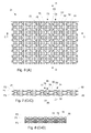
- the heat transfer plate 21 has a number of rows 73, 74 where each row 73, 74 comprises alternating tops and grooves, such as top 76 and groove 77 of row 73 and top 76' and groove 77' of row 74.
- the rows 73, 74 extend along a central plane P1 of heat transfer plate 21, between a top plane P2 and a bottom plane P3 of the heat transfer plate 21.
- the central plane P1 is typically a plane that extends in the center of the heat transfer plate 21, in the illustrated embodiment at equal distances from a top side of the heat transfer plate and a bottom side of the heat transfer plate 21.
- the top plane P2 and bottom plane P3 are substantially parallel to the central plane P1 and are located on a respective side of the central plane P1.
- a transition between each top 76 and adjacent groove 77 in the same row 73 is formed by a portion 78 of the heat transfer plate 21 that is inclined relative the central plane P1.
- the row 74 has a corresponding inclined portion 78' between top 76' and groove 77'.
- Flat elongated plate portions 80, 81 extend along the central plane P1 of the heat transfer plate, between the rows 73, 74 of tops and grooves. The rows 73, 74 are thereby separated from each other.
- the flat elongated plate portions 80, 81 may be referred to as reinforcement sections or flow channels, i.e. the plate portions 80, 81 form flow channels between the rows 73, 74 of tops 76 and grooves 77.
- the central plane P1 is located in, or extends along, the center of the flat elongated plate portions 80, 81.
- the planes P1, P2 and P3 are seen from the side in Fig. 7 .
- the tops 76 have respective top surface 85 on a top side 88 of the heat transfer plate 21 and the grooves 77 have a respective bottom surface 86 on a bottom side 89 of the heat transfer plate 21.
- the top side 88 may be referred to as a first side 88 of the heat transfer plate 21 and the bottom side 89 may be referred to as a second side 89 of the heat transfer plate 21.
- the top surface 85 has a contact area that abuts a heat transfer plate that is arranged above (on the top side 88 of) the heat transfer plate 21.
- the bottom surface 86 has a contact area that abuts a heat transfer plate that is arranged below (on the bottom side 89 of) the heat transfer plate 21.
- the contact area of the top surface 85 is larger than the contact area of the bottom surface 86.
- Some of the rows of alternating tops and grooves are parallel to the first side opening 24 and the second side opening 25 of the heat transfer plate 21.
- a first section S1 of a first type is located in the center of the heat transfer plate 21.
- Two sections S2, S2' of a second type are located around the port openings 22, 23.
- Two sections S3, S3' of a third type are located at both sides of the first section S1.
- Two sections S4, S4' of a fourth type are located along the third side 103 and the fourth side 104, and two sections S5, S5' of a fifth type are located along the first side 101 and the second side 102.
- Sections S2, S2' are similar and symmetrical about the axis A2, where axis A2 extend through the center C1 of the plate heat transfer plate 21 and is perpendicular to axis A1.
- Sections S3, S3' are similar and symmetrical about the axis A1.
- Sections S4, S4' are similar and symmetrical about the axis A2 while sections S5, S5' are similar and symmetrical about the axis A1.
- tops and grooves 375 In the first section S1 there are three rows of tops and grooves 375 that extend adjacent each other and symmetrically along axis A1, i.e. there is no plate portion that separates the three rows from each other. These rows of tops and grooves 375 form a central set of axially extending rows of tops and grooves 375.
- the first section S1 has also a first fluid blocker 210 and a second fluid blocker 212 that are arranged on the top surface 88 of the heat transfer plate heat transfer plate 21.
- the fluid blockers 210, 212 are located between the first port opening 22 and the second port opening 23.
- the first fluid blocker 210 is wedge-shaped and has a tapered section 211 that faces the first port opening 22.
- the second fluid blocker 212 is also wedge-shaped and has also a tapered section 213 that faces the second port opening 23.
- a number of the rows of tops and grooves 373 extend in a direction radially outwards from the center C2 of the first port opening 22, thereby forming radially extending rows of tops and grooves 373.
- the radially extending rows of tops and grooves 373 surround a circumference of the first port opening 22.
- the section S2' has corresponding rows of tops and grooves.
- a number of the rows of tops and grooves 374 extend in a longitudinal direction, parallel to the axis A1, thereby forming longitudinally extending rows of tops and grooves 374.
- the section S3' has corresponding rows of tops and grooves.
- a number of the rows of tops and grooves 376 extend in parallel to the third side 103 and with a curvature, thereby forming curved rows of tops and grooves 376.
- the section S4' has corresponding rows of tops and grooves that extend along the fourth side 104.
- the fourth section S4 there is also a third fluid blocker 214 and in section S4' there is a fourth fluid blocker 218. Both of these fluids blockers 214, 218 are arranged on the bottom surface 89 of the heat transfer plate 21.
- the third fluid blocker 214 being located between the first port opening 22 and the third side 103, across a fluid channel 301 that extends along the third side third side 103.
- the fourth fluid blocker 218 is arranged between the second port opening 23 and the fourth side 104, across a fluid channel 302 that extends along the fourth side 104.
- three additional fluid blockers 215, 216, 217 are arranged across the fluid channel 301, while three additional fluid blockers 219, 220, 221 are arranged across the fluid channel 302.
- a fifth fluid blocker 222 is arranged on the bottom surface 89 of the heat transfer plate 21 and extends along the third side 103.
- a sixth fluid blocker 223 is arranged on the bottom surface 89 of the heat transfer plate 21 and extends along the fourth side 104.
- the fourth section S4 has also a first flow reducer 224 while section S4' has a second flow reducer 225. Both flow reducers 224, 225 are arranged on the bottom surface 89 of the heat transfer plate 21.
- the first flow reducer 224 extends from the first port opening 22 to the third side third side 103, in section S4.
- the second flow reducer 225 extends from the second port opening 23 to the fourth side fourth side 104, in section S4'.
- a number of the plate portions that separate the rows of tops and grooves extend first in a direction outwards from the first port opening 22, then in a direction that is parallel to the third side 103 and with a curvature, such that the plate portions comprises curved plate portions 84.
- Section S5 there is a first side row 311 of tops 313 that are located along the first side opening 24, Section S5' has a second side row 312 of tops that are located along the second side opening 25.
- the tops 313 of the first and second side rows 311, 312 have a different pitch than the previously described tops 76 in the rows 73, 74 of tops 76 and grooves 77 that are separated from each other by the plate portions 80, 81 that form flow channels.
- the heat transfer plate 21 has plate portions 87 (flow channels) that extend first in a direction outwards from the first port opening 22, then in a direction that is parallel to the third side 103, to continue with an extension in a direction that is parallel to a direction from the first port opening 22 to the second port opening 23.
- This plate portion 87, or flow channel 87, is indicated a dotted arrow in Fig. 10 .
- the heat transfer plate 21 has also plate portions (flow channels) that separate the rows of tops and grooves extend first in a radial direction outwards from the first port opening 22, then in a direction that is parallel to a direction from the first port opening 22 to the second port opening 23 or in a direction that is parallel to the first side 101, and finally in a radial direction inwards to the second port opening 23.
- This plate portion, or flow channel, is indicated by a dotted arrow 91 in Fig. 10 .
- the heat transfer plate 21 has also at least two plate portions (flow channels) that separate the rows of tops and grooves extend first in a respective radial direction outwards from the first port opening 22. These two flow channels joins with one flow channel that is parallel to a direction from the first port opening 22 to the second port opening 23, or in a direction that is parallel to the first side 101. These at least two radial plate portions and the flow channel they join into is indicated by dotted arrow 92 in Fig. 10 .
- a third embodiment of a by-pass blocker 130 is illustrated.
- the by-pass blocker 130 is located on the heat transfer plates 20 where the heat transfer plates 20 meet the cylindrical casing 11, and prevents the second fluid F2 from taking a short-cut between the heat transfer plates 20 and the inner surface of the cylindrical casing 11 when it flows between the first passage 51 and second passage 52, or when it flows in the opposite direction.
- the by-pass blocker 130 comprises a comb-like structure 133 that extends along the heat transfer plates 20, from the top cover 12 to the bottom cover 13.
- the comb-like structure 133 has gaps 134 into which the edges of the heat transfer plates 20 extends, and is attached to the heat transfer plates 20 by spot-welds.
- the gaps of the comb are typically abutting the edges of the heat transfer plates 20, such that a tight seal may be accomplished. Any remaining gaps may be closed by welding.
- a first seal 131 and a second seal 132 extends from the comb-like structure 133 . These seals 131, 132 are flexible such that they closely abut the interior surface of the cylindrical casing 11, when the by-pass blocker 130 is arranged between the heat transfer plates 20 and the cylindrical casing 11.
- the heat transfer plate 21 may in its third side 103 have two cut-outs 231, 232 and the fourth side 104 may have two cut-outs 233, 234. Each of these cut-outs 231, 232, 233, 234 receives a respective sealing element like element 130.
- the cut-outs in the plate fit into the gaps 134 of the comb-like structure 133.
- the plate heat exchanger may be arranged with a different number of fluid blockers and other locations of the heat exchanger fluid inlets and outlets.
- the plate heat exchanger may be arranged with a different number of fluid blockers and other locations of the heat exchanger fluid inlets and outlets.
Abstract
Description
- The invention relates to a heat transfer plate with a so called roller coaster pattern, which comprises a number of rows where each row has alternating tops and grooves that extend along a central plane of the heat transfer plate, between a top plane and a bottom plane of the heat transfer plate. The top plane and bottom plane are substantially parallel to the central plane and are located on a respective side of the central plane, where a transition between each top and adjacent groove in the same row is formed by a portion of the heat transfer plate that is inclined relative the central plane.
- Today many different types of plate heat exchangers exist and are employed in various applications depending on their type. Some types of plate heat exchangers have a casing that forms a sealed enclosure in which heat transfer plates that are joined are arranged. The heat transfer plates form a stack of heat transfer plates where alternating first and second flow paths for a first and a second fluid are formed in between the heat transfer plates.
- Since the heat transfer plates are surrounded by a casing, the heat exchanger may withstand high pressure levels in comparison with many other types of plate heat exchangers. Some examples of heat exchangers with a casing that surrounds heat transfer plates are found in patent documents
EP2508831 andEP2527775 . The plate heat exchangers disclosed by these documents handle high pressure levels well. However, in some applications the casing has to be relatively thick to be able to handle the desired pressure levels, which increases the total weight as well as the overall cost of the heat exchanger. Also, the heat transfer plates within the casing must be designed for withstanding high pressure levels. However, at the same time the heat transfer plates must be able to efficiency transfer heat. Generally, the heat transfer plates are of a so called chevron type, i.e. have a pattern with a set of elongated ridges and grooves that are inclined to another set of elongated ridges and grooves (sometimes referred to as herringbone pattern). - New types of plate heat exchangers as well as heat transfer plates that may withstand high pressure levels are needed. The heat exchangers and heat transfer plates should preferably require relatively little material for their structure while still ensuring the heat is efficiently transferred between the heat transfer plates.
- It is an object of the invention to at least partly overcome one or more of the above-identified limitations of the prior art. In particular, it is an object to provide a new heat transfer plate that may withstand high pressure levels while still enabling efficient transfer of heat. Still other objectives, features, aspects and advantages of the invention will appear from the following detailed description as well as from the drawings.
- Thus, a heat transfer plate is provided, which is configured to be arranged in a plate heat exchanger and comprises: a first side, a second side, a third side and a fourth side that form a periphery of the heat transfer plate, the first side being opposite to the second side and the third side being opposite to the fourth side; a first port opening and a second port opening that are arranged at a distance from each other for allowing a first fluid to flow over a top surface of the heat transfer plate, from the first port opening to the second port opening, wherein an axis of the heat transfer plate extends through a center of the first port opening and through a center of the second port opening; a first side opening at the first side and a second side opening at the second side, for allowing a second fluid to flow over a bottom surface of the heat transfer plate, from the first side opening to the second side opening; and a number of rows where each row has alternating tops and grooves that extend along a central plane of the heat transfer plate, between a top plane and a bottom plane of the heat transfer plate, the top plane and bottom plane being substantially parallel to the central plane and located on a respective side of the central plane, where a transition between a top and an adjacent groove in the same row is formed by a portion of the heat transfer plate that is inclined relative the central plane.
- The heat transfer plate has plate portions that extend along the central plane of the heat transfer plate, between the rows of tops and grooves, such that at least some of the rows of tops and grooves are separated from each other and the plate portions thereby form flow channels between the rows of tops and grooves.
- The heat transfer plate has, by virtue of the flow channels between the rows of tops and grooves, a so called roller coaster pattern. The heat transfer plate is advantageous in that it provides strength to the plate portions that form flow channels. Heat transfer plates with traditional plate profiles, such as those of chevron type, tend to flatten under pressure. The roller coaster pattern, on the other hand, is able to maintain a constant gap between adjacent plates at relatively higher pressure levels.
- The heat transfer plate may have the shape of a circular plate with two cut sides that form the first side and the second side, wherein the third side and the fourth side have the form of curved sides.
- This shape is advantageous e.g. in that it allows a flow of fluid through the port openings and over the side openings in a so called multipass configuration (the flows turns in the opposite directions) without the need of any additional flow diverter. Also, the shape may easily match an internal side of a heat exchanger shell in which the plate is arranged, and may offer good flow distribution over the two cut sides.
- At least three of the rows of tops and grooves may extend adjacent each other, symmetrically along the axis that extends through the centers of the first and second port openings, thereby forming a central set of axially extending rows of tops and grooves.
- A number of the rows of tops and grooves may extend in a direction radially outwards from a center of the first port opening, thereby forming radially extending rows of tops and grooves.
- The radially extending rows of tops and grooves may surround a circumference of the first port opening.
- A number of the rows of tops and grooves may extend in a longitudinal direction, parallel to the axis that extends through the centers of the first and second port openings, thereby forming longitudinally extending rows of tops and grooves.
- The above described extensions of rows of tops and grooves all contribute, alone and in combination, to a good distribution of fluids over the both sides of the heat transfer plate. Tests have shown that it is possible to accomplish full or nearly full wetting (flow of fluid) of a heat transfer area of the plate.
- A number of the rows of tops and grooves may extend in parallel to the third side and with a curvature, thereby forming curved rows of tops and grooves.
- The curved rows of tops and grooves are advantageous in that it creates an umbrella-shaped distribution of fluid from the port opening that is located closest to the third side, which facilitates a uniform distribution of fluid across the heat transfer plate.
- The heat transfer plate may comprise a first side row of tops that are located along the first side opening, and a second side row of tops that are located along the second side opening, wherein the tops of the first and second side rows have a different pitch than the tops in the rows of tops and grooves that are separated from each other by the plate portions that form flow channels.
- This is advantageous in that the distribution of the second fluid that flows from the first side opening to the second side opening made be made more uniform.
- The heat transfer plate may comprise a first fluid blocker and a second fluid blocker that are arranged on the top surface of the heat transfer plate and located between the first port opening and the second port opening, wherein the first fluid blocker is wedge-shaped and has a tapered section that faces the first port opening, and the second fluid blocker is wedge-shaped and has a tapered section that faces the second port opening.
- The heat transfer plate may comprise a third fluid blocker and a fourth fluid blocker that are arranged on the bottom surface of the heat transfer plate, the third fluid blocker being arranged between the first port opening and the third side, across a fluid channel that extends along the third side, and the fourth fluid blocker being arranged between the second port opening and the fourth side, across a fluid channel that extends along the fourth side.
- The heat transfer plate may comprise a fifth fluid blocker and a sixth fluid blocker that are arranged on the bottom surface of the heat transfer plate, the fifth fluid blocker extending along the third side, and the sixth fluid blocker extending along the fourth side. The fifth and sixth fluid blockers are advantageous in that they provide good flow distribution over the plate without the need of any additional flow diverter (such as a sleeve fitted between the plate and a plate heat exchanger casing in which the plate is arranged).
- The heat transfer plate may comprise a first flow reducer and a second flow reducer that are arranged on the bottom surface of the heat transfer plate, the first flow reducer extending from the first port opening to the third side, the second flow reducer extending from the second port opening to the fourth side.
- The fluid blockers and the flow reducer are, each alone or in combination, advantageous in that they ensure a uniform distribution of the fluids over the heat transfer plate, including around the port openings.
- A number of the plate portions that separate the rows of tops and grooves may extend first in a direction outwards from the first port opening, then in a direction that is parallel to the third side and with a curvature, such that the plate portions comprises curved plate portions. These plate portions may continue with an extension in a direction that is parallel to a direction from the first port opening to the second port opening.
- A number of the plate portions that separate the rows of tops and grooves may extend first in a radial direction outwards from the first port opening, then in a direction that is parallel to a direction from the first port opening to the second port opening, and finally in a radial direction inwards to the second port opening.
- The third side may comprise two cut-outs and the fourth side comprises two cut-outs. Each of these cut-outs is arranged for receiving a respective sealing element that provides a seal between the plate and a casing of a plate heat exchanger in which the heat transfer plate is arranged. This is advantageous in that facilitates elimination of a by-pass flow of fluid between casing and the plate, without the need of any additional flow diverter. It may also provide support for the plate and any plates that are joined with the plate (to form a stack of heat transfer plates) when mounting it into the casing while still leaving some flexibility for radial, thermal expansion.
- The first, second, third and fourth sides of the heat transfer plate may be configured to be sealed with corresponding sides of a similar heat transfer plate that is located at the top side of the heat transfer plate, and the first and second openings may configured to be sealed with corresponding openings of a similar heat transfer plate that is located at a bottom side of the heat transfer plate.
- According to another aspect a heat exchanger is provided, which comprises a number of heat transfer plates that correspond to the heat transfer plate described above, including any of the above described features. The heat transfer plates are arranged within a casing and are permanently joined to each other such that: a first set of flow channels for a first fluid is formed by every second interspace between the heat transfer plates, with fluid entries and fluid exits at the first and the second port openings; a second set of flow channels for a second fluid is formed by every other, second interspace between the heat transfer plates, with fluid entries and fluid exits at the first and second side openings.
- A first distribution tube extends through the first port openings of the heat transfer plates and comprises a fluid outlet and a fluid inlet that are separated from each other by a first fluid blocker, also referred to as a distribution tube baffle, and a second distribution tube extends through the second port openings of the heat transfer plates and comprises a fluid inlet and a fluid outlet, the fluid inlet of the second distribution tube being arranged, as seen across the heat transfer plates, opposite the fluid outlet of the first distribution tube and the fluid outlet of the second distribution tube being arranged, as seen across the heat transfer plates, opposite the fluid inlet of the first distribution tube.
- A first passage extends along the casing and the first side openings of the heat transfer plates and comprises a fluid outlet section and fluid inlet section that are separated from each other by a second fluid blocker, also referred to as a baffle, and a second passage extends along the casing and the second side openings of the heat transfer plates and comprises a fluid inlet section and a fluid outlet section, the fluid inlet section of the second passage being arranged, as seen across the heat transfer plates, opposite the fluid outlet section of the first passage and the fluid outlet section of the second passage being arranged, as seen across the heat transfer plates, opposite the fluid inlet section of the first passage.
- The heat exchanger is advantageous in that it is very durable and in that it incorporates a heat transfer plate that has all the advantages of the heat transfer plate described above.
- The first and second distribution tubes may extend from a top cover to a bottom cover of the casing, and are attached to the top cover and to the bottom cover.
- This is advantageous in that nozzle loads are supported by the covers, which significantly reduces the stress on the heat transfer plates inside the casing. Also, the distribution tubes work as tie beams, which is advantageous in that the thickness of the covers may be reduced.
- The first distribution tube may comprise a second fluid outlet that is located next to the fluid inlet of the first distribution tube and the second distribution tube may comprise a second fluid inlet that is arranged, as seen across the heat transfer plates, opposite the second fluid outlet of the first distribution tube, and that is separated from the fluid outlet of the second distribution tube by a third fluid blocker. The first passage may comprise a second fluid outlet section that is located next to the fluid inlet section of the first passage, and the second passage may comprise a second fluid inlet section that is arranged, as seen across the heat transfer plates, opposite the second fluid outlet section of the first passage, and that is separated from the fluid outlet section of the second passage by a fourth fluid blocker.
- Still other objectives, features, aspects and advantages of the invention will appear from the following detailed description as well as from the drawings.
- Embodiments of the invention will now be described, by way of example, with reference to the accompanying schematic drawings, in which
-
Fig. 1 is a perspective view of a plate heat exchanger, -
Fig. 2 is a cross-sectional, perspective view of the heat exchanger ofFig. 1 , with the cross-sectional views seen along an inlet for a first fluid and an outlet for a second fluid, -
Fig. 3 , is a cross-sectional view of the heat exchanger ofFig. 1 , showing a flow path of the first fluid, -
Fig. 4 , is a cross-sectional view of the heat exchanger ofFig. 1 , showing a flow path of the second fluid, -
Fig. 5 is a cross-sectional top view of the heat exchanger ofFig. 1 , showing a heat transfer plate that is arranged in the heat exchanger, -
Fig. 6 is an enlarged view of section A inFig. 5 , -
Fig. 7 is a cross-sectional side view as seen along line C-C inFig. 7 , when the heat transfer plate is arranged on top of a similar heat transfer plate, -
Fig. 8 is a cross-sectional side view as seen along line D-D inFig. 7 , when the heat transfer plate is arranged on top of a similar heat transfer plate, -
Fig. 9 is an enlarged view of the heat transfer plate shown inFig. 5 , -
Fig. 10 is an enlarged, sectional view showing a quarter of the heat transfer plate ofFig. 5 , -
Fig. 11 is a top view of a first embodiment of a fluid blocker that may be used for the heat exchanger ofFig. 1 , -
Fig. 12 is a top view of a second embodiment of a fluid blocker that may be used for the heat exchanger ofFig. 1 , and -
Figs 13 - 15 are principal views that illustrate a by-pass blocker that may be used for the heat exchanger ofFig. 1 . - With reference to
Figs 1 and 2 aplate heat exchanger 1 is illustrated. All illustrated parts of theplate heat exchanger 1 are generally made of metal. Some parts like conventional gaskets may be made of other materials. Theplate heat exchanger 1 has acasing 10 in the form of acylindrical casing 11 that is sealed by atop cover 12 and abottom cover 13, such that a sealed enclosure is formed within thecasing 10. Theplate heat exchanger 1 has in the top cover 12 a firstheat exchanger inlet 3 for a first fluid F1 and has in the bottom cover 13 a firstheat exchanger outlet 4 for the first fluid F1. A secondheat exchanger inlet 5 for a second fluid F2 is arranged in thecylindrical casing 11, at an end of thecylindrical casing 11 that is proximate thebottom cover 13. A secondheat exchanger outlet 6 for the second fluid F2 is arranged in thecylindrical casing 11, at an end of thecylindrical casing 11 that is proximate thetop cover 12. Each of theinlets outlets inlets outlets - A number of
heat transfer plates 20 are arranged within thecasing 10 and are permanently joined to each other, for example by welding, to form a stack ofheat transfer plates 201, such that interspaces are formed between the heat transfer plates in thestack 201. Every second interspace between theheat transfer plates 20 forms a first set offlow channels 31 for the first fluid F1, while every other, second interspace between theheat transfer plates 20 forms a second set offlow channels 32 for the second fluid F2. - With further reference to
Fig. 5 aheat transfer plate 21 is shown. Theheat transfer plates 20 within thecasing 10 may each be of the same type as theheat transfer plate 21. Thus, every one or some heat transfer plate in thestack 201 may have the form of theheat transfer plate 21 shown inFig. 5 . However, every second heat transfer plate in thestack 201 may be rotated 180° about an axis A1 that is parallel to theheat transfer plate 21 and that extends through a center C1 of theheat transfer plate 21, through a center C2 of afirst port opening 22 and through a center C3 of asecond port opening 23. Theport openings Fig. 7 ) of theheat transfer plate 21, from thefirst port opening 22 to the second port opening 23 or in the opposite direction. - The
heat transfer plate 21 has afirst side 101, asecond side 102, athird side 103 and afourth side 104 that form a periphery of theheat transfer plate 21. Thefirst side 101 is opposite to thesecond side 102 and thethird side 103 is opposite to thefourth side 104. As may be seen fromFig. 5 , theheat transfer plate 21 has the shape of a circular plate with two cut sides that form thefirst side 101 and thesecond side 102. Thethird side 103 and thefourth side 104 have the form of curved sides. Specifically, thethird side 103 and thefourth side 104 form a respective circular arc with its centers in the center C1 of theheat transfer plate 21. - To accomplish the first set of
flow channels 31 and the second set offlow channels 32, thefirst port opening 22 and the second port opening 23 of aheat transfer plate 21 in thestack 201 is welded to similar first and second port openings of a first, adjacent (upper) heat transfer plate, around their entire peripheries such that a flow boundary is formed for the second fluid F2. Additionally, the entire periphery of theheat transfer plate 21 in thestack 201 is welded to similar periphery of a second, adjacent (lower) heat transfer plate. The first fluid F1 may then enter theheat transfer plates 20 only viafirst port openings 22 andsecond port openings 23 of the heat transfer plates in thestack 201, while it cannot escape outside the periphery of theheat transfer plates 20. The second fluid F2 may enter theheat transfer plates 20 at their peripheries but will not flow into the port openings since they are sealed. - Thus, the
heat transfer plates 20 are joined to each other alternatively at their ports respectively at their peripheries. The space, or channels, formed between theheat transfer plates 20 are referred to as interspaces. This is done for all plates in thestack 201, and means that the first, second, third andfourth sides second port openings - The first set of
flow channels 31 for the first fluid F1 is then formed between every second interspace between theheat transfer plates 20, withfluid entries 28 at thefirst port opening 22 and fluid exits 29 at thesecond port openings 23. When the flow of the first fluid F1 over aheat transfer plate 21 is reversed, then thefluid entry 28 at thefirst port opening 22 becomes a fluid exit and the and thefluid exit 29 at the second port opening 23 becomes a fluid entry. - The second set of
flow channels 32 for the second fluid F2 is formed between every other, second interspace between theheat transfer plates 20, with, for every heat transfer plate, afluid entry 26 at afirst side opening 24 at thefirst side 101 and afluid exit 27 at a second side opening 25 at thesecond side 102. When the flow of the second fluid F2 over aheat transfer plate 21 is reversed, then thefluid entry 26 at thefirst side 101 becomes a fluid exit and the and thefluid exit 27 at thesecond side 102 becomes a fluid entry. Thus, thefirst side opening 24 and the second side opening 25 allow the second fluid F2 to flow over a bottom surface 89 (seeFig. 7 ) of theheat transfer plate 21, from thefirst side opening 24 to the second side opening 25 or in the opposite direction. - As will be further shown below, the flow direction of the first fluid F1 is for some of the heat transfer plates in the
stack 201 opposite that of some of the other heat transfer plates, which means that the first set offlow channels 31 has fluid entries at thefirst port openings 22 and exits and thesecond port openings 23, or entries at thesecond port openings 23 and exits at thefirst port openings 22, depending on at which port opening the first fluid F1 enters (depending on the flow direction of the first fluid F1). In a similar manner, the flow direction of the second fluid F2 is for some of the heat transfer plates in thestack 201 opposite that of some of the other heat transfer plates. This means that the second set offlow channels 32 has fluid entries at thefirst sides 101 and exits at thesecond sides 102, or entries at thesecond sides 102 and exits at thefirst sides 101, depending on at which side the second fluid F2 enters (depending on the flow direction of the second fluid F2). - With reference to
Fig. 3 , theplate heat exchanger 1 has afirst distribution tube 41 that extends through thefirst port openings 22 of theheat transfer plates 20. Thefirst distribution tube 41 and has afluid outlet 43 andfluid inlet 44 that are separated from each other by afirst fluid blocker 61. Each of thefluid outlet 43 and thefluid inlet 44 of thefirst distribution tube 41 has the shape of an elongated opening, or through hole, that extends along a respective length of thefirst distribution tube 41. Thefirst fluid blocker 61 has the shape of disc that is, at a peripheral edge of thedisc 61, welded to the interior of thefirst distribution tube 41, such that no fluid may flow past thefirst fluid blocker 61. An end of thefirst distribution tube 41 that extends through thetop cover 12 forms the firstheat exchanger inlet 3. - The
plate heat exchanger 1 hassecond distribution tube 42 that extends through thesecond port openings 23 of theheat transfer plates 20. Thesecond distribution tube 42 has afluid inlet 46 and afluid outlet 47. Thefluid inlet 46 of thesecond distribution tube 42 is arranged, as seen across theheat transfer plates 20, opposite thefluid outlet 43 of thefirst distribution tube 41. Thefluid outlet 47 of thesecond distribution tube 42 is arranged, as seen across theheat transfer plates 20, opposite thefluid inlet 44 of thefirst distribution tube 41. Each of thefluid inlet 46 and thefluid outlet 47 of thesecond distribution tube 42 has the shape of an elongated opening, or through hole, that extends along a respective length of thesecond distribution tube 42. - In this context, "across the heat transfer plates" may refer to a first direction from the
first port opening 22 to the second port opening 23 of aheat transfer plate 21, or to a second direction that is opposite the first direction. These directions are parallel to a planar extension of the heat transfer plates, and to the axis A1. - The
fluid outlet 43 of thefirst distribution tube 41 is an outlet in the sense that the first fluid F1 may, after it has entered thefirst distribution tube 41 via the firstheat exchanger inlet 3, flow out from thefirst distribution tube 41 via thefluid outlet 43 and into interspaces between theheat transfer plates 20, where thefluid entries 28 of thefirst port openings 22 face thefirst distribution tube 41. Thus, allfluid entries 28 atfirst port openings 22 of heat transfer plates that face thefluid outlet 43 of thefirst distribution tube 41 will receive the first fluid F1 from thefirst distribution tube 41. In these interspaces the first fluid F1 flows across heat transfer plates and eventually out from the interspaces at the fluid exits 29 of thesecond port openings 23. The fluid thereafter flows into thefluid inlet 46 of thesecond distribution tube 42, thus making thefluid inlet 46 an "inlet". This applies for all heat transfer plates between plane P4 inFig. 3 and thetop cover 12. - When the first fluid F1 has flowed into the
second distribution tube 42 via thefluid inlet 46, it flows further in thesecond distribution tube 42 and to thefluid outlet 47 where it, at thesecond port openings 23, leaves thesecond distribution tube 42 via the fluid outlet 47 (making thefluid outlet 47 act as an "outlet"). The first fluid F1 then enters interspaces between theheat transfer plates 20, at thesecond port openings 23 of theheat transfer plates 20 which thereby act as fluid entries. The first fluid F1 then flows in the interspaces, i.e. across heat transfer plates, exits the interspaces at thefirst port openings 22, which thereby act as fluid exits, and flows into thefirst distribution tube 41 via itsfluid inlet 44. The flow of the first fluid F1 from thefluid outlet 47 of thesecond distribution tube 42 to thefluid inlet 44 of thefirst distribution tube 41 applies for all heat transfer plates that are located between plane P4 and P5 inFig. 3 . - The
first distribution tube 41 has also asecond fluid outlet 45 that is located next to itsfluid inlet 44. The second distribution tube has asecond fluid inlet 48 that is located, as seen across theheat transfer plates 20, opposite thesecond fluid outlet 45 of thefirst distribution tube 41. Thesecond fluid inlet 48 is separated from thefluid outlet 47 of thesecond distribution tube 42 by athird fluid blocker 62. - Each of the
second fluid outlet 45 of thefirst distribution tube 41 and thesecond fluid inlet 48 of thesecond distribution tube 42 has the shape of an elongated opening, or through hole, that extends along a length of thefirst distribution tube 41 respectively along a length of thesecond distribution tube 42. Thethird fluid blocker 62 has the shape of disc that is, at a peripheral edge of the disc, welded to the interior of thesecond distribution tube 42, such that no fluid may flow past thethird fluid blocker 62. - After the first fluid F1 has entered the
first distribution tube 41 via itsfluid inlet 44, it flows further in thefirst distribution tube 41 and to itssecond fluid outlet 45. The first fluid F1 leaves thefirst distribution tube 41 via thesecond fluid outlet 45 and flows into interspaces atfirst port openings 22. The first fluid F1 then flows in the interspaces, across the heat transfer plates that form the interspaces, out from the interspaces viasecond port openings 23 of theheat transfer plates 20 and into thesecond distribution tube 42 via thesecond fluid inlet 48. The flow of the first fluid F1 from thesecond fluid outlet 45 of thefirst distribution tube 41 to thesecond fluid inlet 48 of thesecond distribution tube 42 applies for all heat transfer plates that are located between the plane P5 and thebottom cover 13. The first fluid F1 exits thesecond distribution tube 42 via the firstheat exchanger outlet 4, which is formed by a part of thesecond distribution tube 42 that extends out through thebottom cover 13. - The general flow path of the first fluid F1 is illustrated by the curved arrow marked with reference numeral "F1 ".
- As may be seen, the first and
second distribution tubes top cover 12 to thebottom cover 13 of thecasing 10. Thefirst distribution tube 41 has an end that extends through thebottom cover 13 and thesecond distribution tube 42 has an end that extends through thetop cover 12. The ends that extend through thecovers plate heat exchanger 1. The first andsecond distribution tubes top cover 12 and to thebottom cover 13, typically by welding, which increases the pressure resistance of theplate heat exchanger 1. - A
first end plate 18 is arranged between theheat transfer plates 20 and thetop cover 12, and asecond end plate 19 is arranged between theheat transfer plates 20 and thebottom cover 13. Each of the first andsecond distribution tubes end plates distributions tubes - With reference to
Fig. 4 , theplate heat exchanger 1 has afirst passage 51 that extends along thecasing 10 and thefirst sides 24 of theheat transfer plates 20. Thefirst passage 51 has afluid outlet section 53 andfluid inlet section 54 that are separated from each other by asecond fluid blocker 63. - The
plate heat exchanger 1 has also asecond passage 52, which extends along thecasing 10 and thesecond sides 25 of theheat transfer plates 20. Thus, thesecond passage 52 is, as seen across theheat transfer plates 20, opposite thefirst passage 51. Thesecond passage 52 has afluid inlet section 56 and afluid outlet section 57. Thefluid inlet section 56 is arranged, as seen across theheat transfer plates 20, opposite thefluid outlet section 53 of thefirst passage 51. Thefluid outlet section 57 of thesecond passage 52 is arranged, as seen across theheat transfer plates 20, opposite thefluid inlet section 54 of thefirst passage 51. - The
first passage 51 has a secondfluid outlet section 55 that is located next to itsfluid inlet section 54. Thesecond passage 52 has a secondfluid inlet section 58 that is arranged, as seen across theheat transfer plates 20, opposite the secondfluid outlet section 55 of thefirst passage 51. The secondfluid inlet section 58 of thesecond passage 52 is separated from thefluid outlet section 57 of thesecond passage 52 by afourth fluid blocker 64. - In detail, the
first passage 51 is formed by a space between thefirst sides 24 of theheat transfer plates 20 and an interior surface 14 (seeFig. 5 ) of thecylindrical casing 11 that faces thefirst sides 24, between thetop cover 12 and thebottom cover 13. Thesecond passage 52 is formed by a corresponding space between thesecond sides 25 of theheat transfer plates 20 and surface 14' of thecylindrical casing 11 that faces thesecond sides 25, between thetop cover 12 and thebottom cover 13. - The second fluid F2 enters the
first passage 51 via the secondheat exchanger inlet 5. The second fluid F2 next leaves thefirst passage 51 by flowing out from thefirst passage 51 via thefluid outlet section 53 of thefirst passage 51, into interspaces between theheat transfer plates 20, at thefirst sides 24 of theheat transfer plates 20 where thefluid entries 26 are located. All interspaces, or openings at thefirst sides 24 of theheat transfer plates 20, that are located between thebottom cover 13 and the plane P6 form thefluid outlet section 53 of thefirst passage 51. Thus, when the second fluid F2 flows out from thefirst passage 51, it flows into interspaces that are part of the second set offlow channels 32. The second fluid F2 then flows acrossheat transfer plates 20 and exits theheat transfer plates 20 at theinlet section 56 of thesecond passage 52, i.e. the second fluid F2 flows into thesecond passage 52 at itsfluid inlet section 56. All interspaces, or openings at thesecond sides 25 of theheat transfer plates 20 that are located between thebottom cover 13 and the plane P6 form thefluid inlet section 56 for thesecond passage 52. - After the second fluid F2 has entered the
second passage 52 via thefluid inlet section 56, it flows in thesecond passage 52, towards thefluid outlet section 57 of thesecond passage 52. All interspaces, or openings atsecond side openings 25 of theheat transfer plates 20 that are located between plane P6 and thefourth fluid blocker 64, or plane P7, form thefluid outlet section 57 of thesecond passage 52. The second fluid F2 flows out from thesecond passage 52, into the interspaces of thefluid outlet section 57, acrossheat transfer plates 20 and exits the interspaces via thefluid inlet section 54 of thefirst passage 51. All interspaces, or openings at thefirst sides 24 of theheat transfer plates 20 that are located between the plane P6 and plane P7, form thefluid inlet section 54 of thefirst passage 51. - When the second fluid F2 has entered the
first passage 51 via thefluid inlet section 54, it flows in thefirst passage 51, towards the secondfluid outlet section 55 of thesecond passage 52. All interspaces, or openings atfirst sides 24 of theheat transfer plates 20 that are located between plane P7 and thetop cover 12 form the secondfluid outlet section 55 of thefirst passage 51. The second fluid F2 flows via the secondfluid outlet section 55 out from thefirst passage 51, into the interspaces at the secondfluid outlet section 55, acrossheat transfer plates 20 and exits the interspaces via the secondfluid inlet section 58 of thesecond passage 52. All interspaces, or openings at the second side opening 25 of theheat transfer plates 20 that are located between the plane P7 and thetop cover 12 form the secondfluid inlet section 58 of thesecond passage 52. After the second fluid F2 has flown into thesecond passage 52 at the secondfluid inlet section 58, it exits thesecond passage 52 via the secondheat exchanger outlet 6. - The flow path of the second fluid F2 is illustrated by the curved arrow marked with reference numeral "F2".
- As may be seen, the planes P4-P7 are defined by the fluid blockers 61-64. Specifically, plane P4 coincides with the
first fluid blocker 61, plane P6 coincides with thesecond fluid blocker 63, plane P5 coincides with thethird fluid blocker 62 and plane P7 coincides with thefourth fluid blocker 64. - The
plate heat exchanger 1 represents one possible embodiment of a plate heat exchanger with first and second distribution tubes respectively first and second passages for a first and a second fluid. The described embodiment has a multipass configuration and is typically used in a so called a single phase application. In other embodiments, for example when the heat exchanger is used in a condenser or reboiler application, then a single pass configuration may be used. The inlets and outlets for the second fluid may then be located at the center of the shell. - With reference to
Fig. 11 thesecond fluid blocker 63, or baffle, may be an integral part of aheat transfer plate 21, with aperipheral edge 67 that abuts or are very close to the interior surface 14 (seeFig. 5 ) of thecylindrical casing 11, and with aperipheral edge section 66 that is joined with the first side opening 24 of theheat transfer plate 21. Thesecond fluid blocker 63 may also have the form of a partial disc, as shown by the fluid blocker 63' ofFig. 12 . The fluid blocker 63' also hasperipheral edges heat transfer plate 21 and along theinner surface 14 of thecasing 10. - To support the
second fluid blocker 63 theplate heat exchanger 1 may have a rod 69 (seeFig. 4 ) that extends along thefirst passage 51, from aninterior support surface 15 of thecasing 10 and to thesecond fluid blocker 63. Thesupport surface 15 may be part of theend plate 19, or thebottom cover 13 in case no end plate is used. Therod 69 may typically extend from thesupport surface 15 and to a similar support surface on theother end plate 18, or on thetop cover 12 in case no end plates are used. Therod 69 may then extend through a through hole 68 (seeFigs 11 and 12 ) in thesecond fluid blocker 63, 63' and is, e.g. by a spot weld, connected to thesecond fluid blocker 63, 63'. This effectively accomplishes a support for thesecond fluid blocker 63, 63', in a direction along thefirst passage 51. A similar rod may be arranged in thesecond passage 52 for supporting thefourth fluid blocker 64. - Turning back to
Fig 5 and with further reference toFigs 6 - 8 , theheat transfer plate 21 that may be used for theheat exchanger 1 ofFig. 1 is shown. Theheat transfer plate 21 has a number ofrows row groove 77 ofrow 73 and top 76' and groove 77' ofrow 74. Therows heat transfer plate 21, between a top plane P2 and a bottom plane P3 of theheat transfer plate 21. The central plane P1 is typically a plane that extends in the center of theheat transfer plate 21, in the illustrated embodiment at equal distances from a top side of the heat transfer plate and a bottom side of theheat transfer plate 21. The top plane P2 and bottom plane P3 are substantially parallel to the central plane P1 and are located on a respective side of the central plane P1. - A transition between each top 76 and
adjacent groove 77 in thesame row 73 is formed by aportion 78 of theheat transfer plate 21 that is inclined relative the central plane P1. Therow 74 has a corresponding inclined portion 78' between top 76' and groove 77'. Flatelongated plate portions rows rows elongated plate portions plate portions rows tops 76 andgrooves 77. Generally, the central plane P1 is located in, or extends along, the center of the flatelongated plate portions Fig. 7 . - The tops 76 have respective
top surface 85 on atop side 88 of theheat transfer plate 21 and thegrooves 77 have arespective bottom surface 86 on abottom side 89 of theheat transfer plate 21. Thetop side 88 may be referred to as afirst side 88 of theheat transfer plate 21 and thebottom side 89 may be referred to as asecond side 89 of theheat transfer plate 21. Thetop surface 85 has a contact area that abuts a heat transfer plate that is arranged above (on thetop side 88 of) theheat transfer plate 21. Thebottom surface 86 has a contact area that abuts a heat transfer plate that is arranged below (on thebottom side 89 of) theheat transfer plate 21. For several, most or even all of the tops and grooves the contact area of thetop surface 85 is larger than the contact area of thebottom surface 86. Some of the rows of alternating tops and grooves are parallel to thefirst side opening 24 and the second side opening 25 of theheat transfer plate 21. - With reference to
Figs 9 and10 theheat transfer plate 21 is shown in greater detail and has different type of sections with different characteristics. A first section S1 of a first type is located in the center of theheat transfer plate 21. Two sections S2, S2' of a second type are located around theport openings third side 103 and thefourth side 104, and two sections S5, S5' of a fifth type are located along thefirst side 101 and thesecond side 102. - Sections S2, S2' are similar and symmetrical about the axis A2, where axis A2 extend through the center C1 of the plate
heat transfer plate 21 and is perpendicular to axis A1. Sections S3, S3' are similar and symmetrical about the axis A1. Sections S4, S4' are similar and symmetrical about the axis A2 while sections S5, S5' are similar and symmetrical about the axis A1. - In the first section S1 there are three rows of tops and
grooves 375 that extend adjacent each other and symmetrically along axis A1, i.e. there is no plate portion that separates the three rows from each other. These rows of tops andgrooves 375 form a central set of axially extending rows of tops andgrooves 375. - The first section S1 has also a
first fluid blocker 210 and asecond fluid blocker 212 that are arranged on thetop surface 88 of the heat transfer plateheat transfer plate 21. Thefluid blockers first port opening 22 and thesecond port opening 23. Thefirst fluid blocker 210 is wedge-shaped and has a taperedsection 211 that faces thefirst port opening 22. Thesecond fluid blocker 212 is also wedge-shaped and has also atapered section 213 that faces thesecond port opening 23. - In the second section S2 a number of the rows of tops and
grooves 373 extend in a direction radially outwards from the center C2 of thefirst port opening 22, thereby forming radially extending rows of tops andgrooves 373. The radially extending rows of tops andgrooves 373 surround a circumference of thefirst port opening 22. The section S2' has corresponding rows of tops and grooves. - In the third section S3 a number of the rows of tops and
grooves 374 extend in a longitudinal direction, parallel to the axis A1, thereby forming longitudinally extending rows of tops andgrooves 374. The section S3' has corresponding rows of tops and grooves. - In the fourth section S4 a number of the rows of tops and
grooves 376 extend in parallel to thethird side 103 and with a curvature, thereby forming curved rows of tops andgrooves 376. The section S4' has corresponding rows of tops and grooves that extend along thefourth side 104. - In the fourth section S4 there is also a
third fluid blocker 214 and in section S4' there is afourth fluid blocker 218. Both of thesefluids blockers bottom surface 89 of theheat transfer plate 21. Thethird fluid blocker 214 being located between thefirst port opening 22 and thethird side 103, across afluid channel 301 that extends along the third sidethird side 103. Thefourth fluid blocker 218 is arranged between the second port opening 23 and thefourth side 104, across afluid channel 302 that extends along thefourth side 104. To accomplish efficient blocking of thefluid channel 301, threeadditional fluid blockers fluid channel 301, while threeadditional fluid blockers fluid channel 302. - In the fourth section S4 there is a
fifth fluid blocker 222 is arranged on thebottom surface 89 of theheat transfer plate 21 and extends along thethird side 103. In the section S4' there is asixth fluid blocker 223 that is arranged on thebottom surface 89 of theheat transfer plate 21 and extends along thefourth side 104. - The fourth section S4 has also a
first flow reducer 224 while section S4' has asecond flow reducer 225. Both flowreducers bottom surface 89 of theheat transfer plate 21. Thefirst flow reducer 224 extends from thefirst port opening 22 to the third sidethird side 103, in section S4. Thesecond flow reducer 225 extends from the second port opening 23 to the fourth sidefourth side 104, in section S4'. - A number of the plate portions that separate the rows of tops and grooves extend first in a direction outwards from the
first port opening 22, then in a direction that is parallel to thethird side 103 and with a curvature, such that the plate portions comprisescurved plate portions 84. - In the fifth section S5 there is a
first side row 311 oftops 313 that are located along thefirst side opening 24, Section S5' has asecond side row 312 of tops that are located along thesecond side opening 25. Thetops 313 of the first andsecond side rows rows tops 76 andgrooves 77 that are separated from each other by theplate portions - As may be seen from the figures, the
heat transfer plate 21 has plate portions 87 (flow channels) that extend first in a direction outwards from thefirst port opening 22, then in a direction that is parallel to thethird side 103, to continue with an extension in a direction that is parallel to a direction from thefirst port opening 22 to thesecond port opening 23. Thisplate portion 87, or flowchannel 87, is indicated a dotted arrow inFig. 10 . - The
heat transfer plate 21 has also plate portions (flow channels) that separate the rows of tops and grooves extend first in a radial direction outwards from thefirst port opening 22, then in a direction that is parallel to a direction from thefirst port opening 22 to the second port opening 23 or in a direction that is parallel to thefirst side 101, and finally in a radial direction inwards to thesecond port opening 23. This plate portion, or flow channel, is indicated by a dottedarrow 91 inFig. 10 . - The
heat transfer plate 21 has also at least two plate portions (flow channels) that separate the rows of tops and grooves extend first in a respective radial direction outwards from thefirst port opening 22. These two flow channels joins with one flow channel that is parallel to a direction from thefirst port opening 22 to the second port opening 23, or in a direction that is parallel to thefirst side 101. These at least two radial plate portions and the flow channel they join into is indicated bydotted arrow 92 inFig. 10 . - With reference to
Figs 13 - 15 , a third embodiment of a by-pass blocker 130 is illustrated. The by-pass blocker 130 is located on theheat transfer plates 20 where theheat transfer plates 20 meet thecylindrical casing 11, and prevents the second fluid F2 from taking a short-cut between theheat transfer plates 20 and the inner surface of thecylindrical casing 11 when it flows between thefirst passage 51 andsecond passage 52, or when it flows in the opposite direction. The by-pass blocker 130 comprises a comb-like structure 133 that extends along theheat transfer plates 20, from thetop cover 12 to thebottom cover 13. The comb-like structure 133 hasgaps 134 into which the edges of theheat transfer plates 20 extends, and is attached to theheat transfer plates 20 by spot-welds. The gaps of the comb are typically abutting the edges of theheat transfer plates 20, such that a tight seal may be accomplished. Any remaining gaps may be closed by welding. From the comb-like structure 133 afirst seal 131 and asecond seal 132 extends. Theseseals cylindrical casing 11, when the by-pass blocker 130 is arranged between theheat transfer plates 20 and thecylindrical casing 11. - For providing a good fit between the by-
pass blocker 130 and the heat transfer plates, theheat transfer plate 21 may in itsthird side 103 have two cut-outs fourth side 104 may have two cut-outs outs element 130. The cut-outs in the plate fit into thegaps 134 of the comb-like structure 133. - From the description above follows that, although various embodiments of the invention have been described and shown, the invention is not restricted thereto, but may also be embodied in other ways within the scope of the subject-matter defined in the following claims. For example, the plate heat exchanger may be arranged with a different number of fluid blockers and other locations of the heat exchanger fluid inlets and outlets. Thus, even though three so called passes for the fluids are illustrated, another number of passes for the fluids may be accomplished just as well.
Claims (20)
- A heat transfer plate configured to be arranged in a plate heat exchanger (2), the heat transfer plate comprising
a first side (101), a second side (102), a third side (103) and a fourth side (104) that form a periphery of the heat transfer plate, the first side (101) being opposite to the second side (102) and the third side (103) being opposite to the fourth side (104),
a first port opening (22) and a second port opening (23) that are arranged at a distance from each other for allowing a first fluid (F1) to flow over a top surface (88) of the heat transfer plate, from the first port opening (22) to the second port opening (23), wherein an axis (A1) of the heat transfer plate extends through a center (C2) of the first port opening and through a center (C3) of the second port opening (23),
a first side opening (24) at the first side (101) and a second side opening (25) at the second side (102), for allowing a second fluid (F2) to flow over a bottom surface (89) of the heat transfer plate, from the first side opening (24) to the second side opening (25),
a number of rows (73, 74) where each row (73, 74) has alternating tops (76) and grooves (77) that extend along a central plane (P1) of the heat transfer plate, between a top plane (P2) and a bottom plane (P3) of the heat transfer plate, the top plane (P2) and bottom plane (P3) being substantially parallel to the central plane (P1) and located on a respective side of the central plane (P1), where a transition between a top (76) and an adjacent groove (77) in the same row (73) is formed by a portion (78) of the heat transfer plate (21) that is inclined relative the central plane (P1),
characterized by
plate portions (80, 81) that extend along the central plane (P1) of the heat transfer plate, between the rows (73, 74) of tops (76) and grooves (77), such that at least some of the rows (73, 74) of tops (76) and grooves (77) are separated from each other and the plate portions (80, 81) thereby form flow channels between the rows (73, 74) of tops (76) and grooves (77). - A heat transfer plate according to claim 1, having the shape of a circular plate with two cut sides that form the first side (101) and the second side (102), wherein the third side (103) and the fourth side (104) have the form of curved sides.
- A heat transfer plate according to claim 1 or 2, wherein at least three of the rows of tops and grooves extend adjacent each other, symmetrically along the axis (A1) that extends through the centers (C2, C3) of the first and second port openings (22, 23), thereby forming a central set of axially extending rows of tops and grooves (375).
- A heat transfer plate according to any one of claims 1 - 3, wherein a number of the rows of tops and grooves extend in a direction radially outwards from a center (C2) of the first port opening (22), thereby forming radially extending rows of tops and grooves (373).
- A heat transfer plate according to claim 4, wherein the radially extending rows of tops and grooves (373) surrounds a circumference of the first port opening (22).
- A heat transfer plate according to any one of claims 1 - 5, wherein a number of the rows of tops and grooves extend in a longitudinal direction, parallel to the axis (A1) that extends through the centers (C2, C3) of the first and second port openings (22, 23), thereby forming longitudinally extending rows of tops and grooves (374).
- A heat transfer plate according to any one of claims 1 - 6, wherein a number of the rows of tops and grooves extend in parallel to the third side (103) and with a curvature, thereby forming curved rows of tops and grooves (376).
- A heat transfer plate according to any one of claims 1 - 7, comprising a first side row (311) of tops (313) that are located along the first side opening (24), and a second side row (312) of tops that are located along the second side opening (25), wherein the tops (313) of the first and second side rows (311, 312) have a different pitch than the tops (76) in the rows (73, 74) of tops (76) and grooves (77) that are separated from each other by the plate portions (80, 81) that form flow channels.
- A heat transfer plate according to any one of claims 1 - 8, comprising a first fluid blocker (210) and a second fluid blocker (212) that are arranged on the top surface (88) of the heat transfer plate and located between the first port opening (22) and the second port opening (23), wherein the first fluid blocker (210) is wedge-shaped and has a tapered section (211) that faces the first port opening (22), and the second fluid blocker (212) is wedge-shaped and has a tapered section (213) that faces the second port opening (23).
- A heat transfer plate according to any one of claims 1 - 9, comprising a third fluid blocker (214) and a fourth fluid blocker (218) that are arranged on the bottom surface (89) of the heat transfer plate,
the third fluid blocker (214) being arranged between the first port opening (22) and the third side (103), across a fluid channel (301) that extends along the third side (103), and
the fourth fluid blocker (218) being arranged between the second port opening (23) and the fourth side (104), across a fluid channel (302) that extends along the fourth side (104). - A heat transfer plate according to any one of claims 1 - 10, comprising a fifth fluid blocker (222) and a sixth fluid blocker (223) that are arranged on the bottom surface (89) of the heat transfer plate, the fifth fluid blocker (222) extending along the third side (103), and the sixth fluid blocker (223) extending along the fourth side (104).
- A heat transfer plate according to any one of claims 1 - 11, comprising a first flow reducer (224) and a second flow reducer (225) that are arranged on the bottom surface (89) of the heat transfer plate, the first flow reducer (224) extending from the first port opening (22) to the third side (103), the second flow reducer (225) extending from the second port opening (23) to the fourth side (104).
- A heat transfer plate according to any one of claims 1 - 12, wherein a number of the plate portions (80, 81) that separate the rows (73, 74) of tops (76) and grooves (77) extend first in a direction outwards from the first port opening (22), then in a direction that is parallel to the third side (103) and with a curvature, such that the plate portions comprises curved plate portions (84).
- A heat transfer plate according to claim 13, wherein the number of the plate portions (80, 81) that extend first in a direction outwards from the first port opening (22), and then in a direction that is parallel to the third side (103), continues with an extension in a direction that is parallel to a direction from the first port opening (22) to the second port opening (23).
- A heat transfer plate according to any one of claims 1 - 14, wherein a number of the plate portions (80, 81) that separate the rows (73, 74) of tops (76) and grooves (77) extend first in a radial direction outwards from the first port opening (22), then in a direction that is parallel to a direction from the first port opening (22) to the second port opening (23), and finally in a radial direction inwards to the second port opening (23).
- A heat transfer plate according to any one of claims 1 - 15, wherein the third side (103) comprises two cut-outs (231, 232) and the fourth side (104) comprises two cut-outs (233, 234), each of the cut-outs (231, 232, 233, 234) being arranged for receiving a respective sealing element (130) that provides a seal between the plate and a plate heat exchanger casing (10) in which the heat transfer plate is arranged.
- A heat transfer plate according to any one of claims 1 - 16, wherein
the first, second, third and fourth sides (101, 102, 103, 104) are configured to be sealed with corresponding sides of a similar heat transfer plate (21') that is located at the top side (88) of the heat transfer plate, and
the first and second openings (22, 23) are configured to be sealed with corresponding openings of a similar heat transfer plate (21 ") that is located at a bottom side (89) of the heat transfer plate. - A plate heat exchanger comprising a number of heat transfer plates (20) according to any one of claims 1 - 17, wherein
the heat transfer plates (20) are arranged within a casing (10) and permanently joined to each other such that:- a first set of flow channels (31) for a first fluid (F1) is formed by every second interspace between the heat transfer plates (20), with fluid entries (28, 29) and fluid exits (28, 29) at the first and the second port openings (22, 23),- a second set of flow channels (32) for a second fluid (F2) is formed by every other, second interspace between the heat transfer plates (20), with fluid entries (26) and fluid exits (27) at the first and second side openings (24, 25), characterized by a first distribution tube (41) that extends through the first port openings (22) of the heat transfer plates (20) and comprises a fluid outlet (43) and a fluid inlet (44) that are separated from each other by a first fluid blocker (61),a second distribution tube (42) that extends through the second port openings (23) of the heat transfer plates (20) and comprises a fluid inlet (46) and a fluid outlet (47), the fluid inlet (46) of the second distribution tube (42) being arranged, as seen across the heat transfer plates (20), opposite the fluid outlet (43) of the first distribution tube (41) and the fluid outlet (47) of the second distribution tube (42) being arranged, as seen across the heat transfer plates (20), opposite the fluid inlet (44) of the first distribution tube (41),
a first passage (51) that extends along the casing (10) and the first side openings (24) of the heat transfer plates (20) and comprises a fluid outlet section (53) and fluid inlet section (54) that are separated from each other by a second fluid blocker (63), and
a second passage (52) that extends along the casing (10) and the second side openings (25) of the heat transfer plates (20) and comprises a fluid inlet section (56) and a fluid outlet section (57), the fluid inlet section (56) of the second passage (52) being arranged, as seen across the heat transfer plates (20), opposite the fluid outlet section (53) of the first passage (51) and the fluid outlet section (57) of the second passage (52) being arranged, as seen across the heat transfer plates (20), opposite the fluid inlet section (54) of the first passage (51). - A plate heat exchanger according to claim 18, wherein the first and second distribution tubes (41, 42)
extend from a top cover (12) to a bottom cover (13) of the casing (10), and
are attached to the top cover (12) and to the bottom cover (13). - A plate heat exchanger according to claim 18 or 19, wherein
the first distribution tube (41) comprises a second fluid outlet (45) that is located next to the fluid inlet (44) of the first distribution tube (41),
the second distribution tube (42) comprises a second fluid inlet (48) that is arranged, as seen across the heat transfer plates (20), opposite the second fluid outlet (45) of the first distribution tube (41), and that is separated from the fluid outlet (47) of the second distribution tube (42) by a third fluid blocker (62),
the first passage (51) comprises a second fluid outlet section (55) that is located next to the fluid inlet section (54) of the first passage (51), and
the second passage (52) comprises a second fluid inlet section (58) that is arranged, as seen across the heat transfer plates (20), opposite the second fluid outlet section (55) of the first passage (51), and that is separated from the fluid outlet section (57) of the second passage (52) by a fourth fluid blocker (64).
Priority Applications (7)
| Application Number | Priority Date | Filing Date | Title |
|---|---|---|---|
| EP14184805.1A EP2988085B1 (en) | 2014-08-22 | 2014-09-15 | Heat transfer plate and plate heat exchanger |
| PL14184805T PL2988085T3 (en) | 2014-08-22 | 2014-09-15 | Heat transfer plate and plate heat exchanger |
| PCT/EP2015/069239 WO2016026958A1 (en) | 2014-08-22 | 2015-08-21 | Heat transfer plate and plate heat exchanger |
| KR1020177007392A KR101918869B1 (en) | 2014-08-22 | 2015-08-21 | Heat transfer plate and plate heat exchanger |
| CN201580044955.XA CN107076520B (en) | 2014-08-22 | 2015-08-21 | Heat transfer plate and plate heat exchanger |
| JP2017510471A JP6445143B2 (en) | 2014-08-22 | 2015-08-21 | Heat transfer plate and plate heat exchanger |
| US15/505,504 US10234212B2 (en) | 2014-08-22 | 2015-08-21 | Heat transfer plate and plate heat exchanger |
Applications Claiming Priority (2)
| Application Number | Priority Date | Filing Date | Title |
|---|---|---|---|
| EP14181947 | 2014-08-22 | ||
| EP14184805.1A EP2988085B1 (en) | 2014-08-22 | 2014-09-15 | Heat transfer plate and plate heat exchanger |
Publications (2)
| Publication Number | Publication Date |
|---|---|
| EP2988085A1 true EP2988085A1 (en) | 2016-02-24 |
| EP2988085B1 EP2988085B1 (en) | 2019-03-20 |
Family
ID=51383650
Family Applications (1)
| Application Number | Title | Priority Date | Filing Date |
|---|---|---|---|
| EP14184805.1A Active EP2988085B1 (en) | 2014-08-22 | 2014-09-15 | Heat transfer plate and plate heat exchanger |
Country Status (10)
| Country | Link |
|---|---|
| US (1) | US10234212B2 (en) |
| EP (1) | EP2988085B1 (en) |
| JP (1) | JP6445143B2 (en) |
| KR (1) | KR101918869B1 (en) |
| CN (1) | CN107076520B (en) |
| DK (1) | DK2988085T3 (en) |
| ES (1) | ES2728297T3 (en) |
| PL (1) | PL2988085T3 (en) |
| PT (1) | PT2988085T (en) |
| WO (1) | WO2016026958A1 (en) |
Cited By (5)
| Publication number | Priority date | Publication date | Assignee | Title |
|---|---|---|---|---|
| US20180112935A1 (en) * | 2016-10-26 | 2018-04-26 | Frost Co., Ltd. | Disk bundle type heat-exchanger |
| EP3372941A1 (en) * | 2017-03-10 | 2018-09-12 | Alfa Laval Corporate AB | Plate package, plate and heat exchanger device |
| IT201800005663A1 (en) * | 2018-05-24 | 2019-11-24 | HEAT EXCHANGER DEVICE | |
| EP3657114A1 (en) * | 2018-11-26 | 2020-05-27 | Alfa Laval Corporate AB | Heat transfer plate |
| US20210131738A1 (en) * | 2019-11-04 | 2021-05-06 | Danfoss A/S | Plate-and-shell heat exchanger and a channel blocking plate for a plate-and-shell heat exchanger |
Families Citing this family (8)
| Publication number | Priority date | Publication date | Assignee | Title |
|---|---|---|---|---|
| EP3179190A1 (en) * | 2015-12-11 | 2017-06-14 | Alfa Laval Corporate AB | Plate heat exchanger |
| KR102019203B1 (en) | 2017-10-02 | 2019-09-06 | 한국원자력연구원 | Printed circuit heat exchange module and heat exchanger |
| US11035626B2 (en) * | 2018-09-10 | 2021-06-15 | Hamilton Sunstrand Corporation | Heat exchanger with enhanced end sheet heat transfer |
| JP6860095B1 (en) * | 2020-01-14 | 2021-04-14 | ダイキン工業株式会社 | Shell and plate heat exchanger |
| JP2022051195A (en) * | 2020-09-18 | 2022-03-31 | サンデン・アドバンストテクノロジー株式会社 | Heat exchanger |
| CN112371852A (en) * | 2020-10-26 | 2021-02-19 | 湖州恒大液压设备有限公司 | Punch circulating internal cooling device of quick forging servo hydraulic machine |
| CN114508955A (en) * | 2020-11-16 | 2022-05-17 | 丹佛斯有限公司 | Plate-and-shell heat exchanger and heat transfer plate for a plate-and-shell heat exchanger |
| US20220299244A1 (en) * | 2021-03-19 | 2022-09-22 | Daikin Industries, Ltd. | Shell and plate heat exchanger for water-cooled chiller and water-cooled chiller including the same |
Citations (9)
| Publication number | Priority date | Publication date | Assignee | Title |
|---|---|---|---|---|
| FR2426879A1 (en) * | 1978-05-26 | 1979-12-21 | Bedue Abel | Condenser for small steam turbine - consists of stacked plates with stepped flanges around holes to form continuous tubes for cooling water |
| EP0177474A2 (en) * | 1984-10-03 | 1986-04-09 | AB Carl Munters | Insertable contact body |
| DE3536316A1 (en) * | 1985-10-11 | 1987-04-16 | Sueddeutsche Kuehler Behr | Laminated oil cooler |
| JPH09138082A (en) * | 1995-11-15 | 1997-05-27 | Ebara Corp | Plate type heat exchanger and its manufacture |
| US20030000688A1 (en) * | 2001-06-29 | 2003-01-02 | Mathur Achint P. | Shell and plate heat exchanger |
| EP2267391A2 (en) * | 2009-06-26 | 2010-12-29 | SWEP International AB | Asymmetric heat exchanger |
| EP2508831A1 (en) | 2011-04-07 | 2012-10-10 | Alfa Laval Corporate AB | Plate heat exchanger |
| EP2527775A1 (en) | 2011-05-25 | 2012-11-28 | Alfa Laval Corporate AB | Heat transfer plate for a plate-and-shell heat exchanger |
| EP2728292A1 (en) * | 2012-10-30 | 2014-05-07 | Alfa Laval Corporate AB | Heat transfer plate and plate heat exchanger comprising such a heat transfer plate |
Family Cites Families (24)
| Publication number | Priority date | Publication date | Assignee | Title |
|---|---|---|---|---|
| FR813272A (en) * | 1936-11-12 | 1937-05-29 | Anciens Etablissements Lamblin | Cooling radiators for engines or other applications |
| JPS535646Y2 (en) * | 1974-04-05 | 1978-02-13 | ||
| US4235287A (en) * | 1975-05-02 | 1980-11-25 | Olin Corporation | Heat exchange panel |
| DE2948586A1 (en) * | 1979-12-03 | 1981-06-25 | Alfa-Laval AB, 14700 Tumba | HEAT EXCHANGER |
| SE444719B (en) | 1980-08-28 | 1986-04-28 | Alfa Laval Ab | PLATE HEAT EXCHANGERS WITH CORRUGATED PLATES WHICH THE CORRUGATORS SUPPOSE THE ACCESSIBLE PLATES AND THE CORRUGGES IN THE STUDY AREA CONSIDERED TO REDUCE THE DISTANCE BETWEEN TWO PLATES |
| JPS5923986Y2 (en) * | 1981-03-04 | 1984-07-16 | 株式会社日阪製作所 | Plate heat exchanger |
| SE443870B (en) * | 1981-11-26 | 1986-03-10 | Alfa Laval Ab | PLATE HEAT EXCHANGERS WITH CORRUGATED PLATES WHICH CORRUGATES SUPPORTS NEARBY PLATES CORRUGATIONS WITHOUT A NUMBER OF CONSUMPTION PARTIES |
| DE3622316C1 (en) | 1986-07-03 | 1988-01-28 | Schmidt W Gmbh Co Kg | Plate heat exchanger |
| SE458806B (en) * | 1987-04-21 | 1989-05-08 | Alfa Laval Thermal Ab | PLATE HEAT EXCHANGER WITH DIFFERENT FLOW RESISTANCE FOR MEDIA |
| JP2604735Y2 (en) | 1992-04-09 | 2000-06-05 | 石川島播磨重工業株式会社 | Plate fin heat exchanger |
| JPH07260384A (en) * | 1994-03-28 | 1995-10-13 | Hisaka Works Ltd | Plate type heat exchanger |
| JP3654669B2 (en) * | 1994-09-28 | 2005-06-02 | 株式会社日阪製作所 | Plate heat exchanger |
| JPH08271171A (en) * | 1995-03-29 | 1996-10-18 | Hisaka Works Ltd | Plate type heat exchanger |
| JPH10267580A (en) * | 1997-03-27 | 1998-10-09 | Hisaka Works Ltd | Plate-type heat exchanger |
| JP3292128B2 (en) | 1998-02-27 | 2002-06-17 | ダイキン工業株式会社 | Plate heat exchanger |
| US6131648A (en) * | 1998-11-09 | 2000-10-17 | Electric Boat Corporation | High pressure corrugated plate-type heat exchanger |
| KR20020006158A (en) | 2000-07-11 | 2002-01-19 | 송문섭 | Hand type of JIG in a mobile station |
| SE526831C2 (en) | 2004-03-12 | 2005-11-08 | Alfa Laval Corp Ab | Heat exchanger plate and plate package |
| JP2006183945A (en) * | 2004-12-28 | 2006-07-13 | Mahle Filter Systems Japan Corp | Oil cooler |
| WO2008024066A1 (en) * | 2006-08-23 | 2008-02-28 | Alfa Laval Corporate Ab | Plate heat exchanger and heat exchanger plant |
| ATE553349T1 (en) * | 2008-12-16 | 2012-04-15 | Alfa Laval Corp Ab | HEAT EXCHANGER |
| SE534765C2 (en) | 2010-04-21 | 2011-12-13 | Alfa Laval Corp Ab | Plate heat exchanger plate and plate heat exchanger |
| JP5763462B2 (en) * | 2011-07-29 | 2015-08-12 | 株式会社ティラド | Header plateless heat exchanger |
| GB2512761A (en) * | 2011-11-28 | 2014-10-08 | Dana Canada Corp | Heat exchanger plates with integral bypass blocking tabs |
-
2014
- 2014-09-15 PT PT14184805T patent/PT2988085T/en unknown
- 2014-09-15 PL PL14184805T patent/PL2988085T3/en unknown
- 2014-09-15 ES ES14184805T patent/ES2728297T3/en active Active
- 2014-09-15 EP EP14184805.1A patent/EP2988085B1/en active Active
- 2014-09-15 DK DK14184805.1T patent/DK2988085T3/en active
-
2015
- 2015-08-21 US US15/505,504 patent/US10234212B2/en active Active
- 2015-08-21 CN CN201580044955.XA patent/CN107076520B/en active Active
- 2015-08-21 KR KR1020177007392A patent/KR101918869B1/en active IP Right Grant
- 2015-08-21 JP JP2017510471A patent/JP6445143B2/en active Active
- 2015-08-21 WO PCT/EP2015/069239 patent/WO2016026958A1/en active Application Filing
Patent Citations (9)
| Publication number | Priority date | Publication date | Assignee | Title |
|---|---|---|---|---|
| FR2426879A1 (en) * | 1978-05-26 | 1979-12-21 | Bedue Abel | Condenser for small steam turbine - consists of stacked plates with stepped flanges around holes to form continuous tubes for cooling water |
| EP0177474A2 (en) * | 1984-10-03 | 1986-04-09 | AB Carl Munters | Insertable contact body |
| DE3536316A1 (en) * | 1985-10-11 | 1987-04-16 | Sueddeutsche Kuehler Behr | Laminated oil cooler |
| JPH09138082A (en) * | 1995-11-15 | 1997-05-27 | Ebara Corp | Plate type heat exchanger and its manufacture |
| US20030000688A1 (en) * | 2001-06-29 | 2003-01-02 | Mathur Achint P. | Shell and plate heat exchanger |
| EP2267391A2 (en) * | 2009-06-26 | 2010-12-29 | SWEP International AB | Asymmetric heat exchanger |
| EP2508831A1 (en) | 2011-04-07 | 2012-10-10 | Alfa Laval Corporate AB | Plate heat exchanger |
| EP2527775A1 (en) | 2011-05-25 | 2012-11-28 | Alfa Laval Corporate AB | Heat transfer plate for a plate-and-shell heat exchanger |
| EP2728292A1 (en) * | 2012-10-30 | 2014-05-07 | Alfa Laval Corporate AB | Heat transfer plate and plate heat exchanger comprising such a heat transfer plate |
Cited By (15)
| Publication number | Priority date | Publication date | Assignee | Title |
|---|---|---|---|---|
| US10724806B2 (en) * | 2016-10-26 | 2020-07-28 | Frost Co., Ltd. | Disk bundle type heat-exchanger |
| US20180112935A1 (en) * | 2016-10-26 | 2018-04-26 | Frost Co., Ltd. | Disk bundle type heat-exchanger |
| EP3800422A1 (en) * | 2017-03-10 | 2021-04-07 | Alfa Laval Corporate AB | Plate for a heat exchanger device |
| TWI676779B (en) * | 2017-03-10 | 2019-11-11 | 瑞典商阿爾法拉瓦公司 | Plate package, plate and heat exchanger device |
| WO2018162199A1 (en) * | 2017-03-10 | 2018-09-13 | Alfa Laval Corporate Ab | Plate package, plate and heat exchanger device |
| EP3372941A1 (en) * | 2017-03-10 | 2018-09-12 | Alfa Laval Corporate AB | Plate package, plate and heat exchanger device |
| US11162736B2 (en) | 2017-03-10 | 2021-11-02 | Alfa Laval Corporate Ab | Plate package, plate and heat exchanger device |
| IT201800005663A1 (en) * | 2018-05-24 | 2019-11-24 | HEAT EXCHANGER DEVICE | |
| WO2019224767A1 (en) * | 2018-05-24 | 2019-11-28 | Ecosfera S.R.L. | Thermal exchanging device |
| EP3657114A1 (en) * | 2018-11-26 | 2020-05-27 | Alfa Laval Corporate AB | Heat transfer plate |
| WO2020108969A1 (en) * | 2018-11-26 | 2020-06-04 | Alfa Laval Corporate Ab | Heat transfer plate |
| JP6978636B1 (en) * | 2018-11-26 | 2021-12-08 | アルファ−ラヴァル・コーポレート・アーベー | Heat transfer plate |
| JP2022507992A (en) * | 2018-11-26 | 2022-01-18 | アルファ-ラヴァル・コーポレート・アーベー | Heat transfer plate |
| US11499786B2 (en) | 2018-11-26 | 2022-11-15 | Alfa Laval Corporate Ab | Heat transfer plate |
| US20210131738A1 (en) * | 2019-11-04 | 2021-05-06 | Danfoss A/S | Plate-and-shell heat exchanger and a channel blocking plate for a plate-and-shell heat exchanger |
Also Published As
| Publication number | Publication date |
|---|---|
| ES2728297T3 (en) | 2019-10-23 |
| WO2016026958A1 (en) | 2016-02-25 |
| US10234212B2 (en) | 2019-03-19 |
| KR20170042759A (en) | 2017-04-19 |
| JP2017528674A (en) | 2017-09-28 |
| CN107076520B (en) | 2019-04-09 |
| CN107076520A (en) | 2017-08-18 |
| KR101918869B1 (en) | 2018-11-14 |
| PT2988085T (en) | 2019-06-07 |
| DK2988085T3 (en) | 2019-06-24 |
| EP2988085B1 (en) | 2019-03-20 |
| PL2988085T3 (en) | 2019-07-31 |
| JP6445143B2 (en) | 2018-12-26 |
| US20170254596A1 (en) | 2017-09-07 |
Similar Documents
| Publication | Publication Date | Title |
|---|---|---|
| EP2988085B1 (en) | Heat transfer plate and plate heat exchanger | |
| EP2981780B1 (en) | Plate heat exchanger and method for constructing multiple passes in the plate heat exchanger | |
| EP3179190A1 (en) | Plate heat exchanger | |
| EP2594884B1 (en) | Plate heat exchanger and method for manufacturing of a plate heat exchanger | |
| US10156401B2 (en) | Plate heat exchanger with distribution tubes | |
| US10393448B2 (en) | Plate heat exchanger | |
| FI84659B (en) | VAERMEVAEXLARE. | |
| US20180231323A1 (en) | Plate Heat Exchanger | |
| EP3112788A1 (en) | Plate heat exchanger |
Legal Events
| Date | Code | Title | Description |
|---|---|---|---|
| PUAI | Public reference made under article 153(3) epc to a published international application that has entered the european phase |
Free format text: ORIGINAL CODE: 0009012 |
|
| 17P | Request for examination filed |
Effective date: 20140918 |
|
| AK | Designated contracting states |
Kind code of ref document: A1 Designated state(s): AL AT BE BG CH CY CZ DE DK EE ES FI FR GB GR HR HU IE IS IT LI LT LU LV MC MK MT NL NO PL PT RO RS SE SI SK SM TR |
|
| AX | Request for extension of the european patent |
Extension state: BA ME |
|
| GRAP | Despatch of communication of intention to grant a patent |
Free format text: ORIGINAL CODE: EPIDOSNIGR1 |
|
| STAA | Information on the status of an ep patent application or granted ep patent |
Free format text: STATUS: GRANT OF PATENT IS INTENDED |
|
| INTG | Intention to grant announced |
Effective date: 20181106 |
|
| GRAJ | Information related to disapproval of communication of intention to grant by the applicant or resumption of examination proceedings by the epo deleted |
Free format text: ORIGINAL CODE: EPIDOSDIGR1 |
|
| STAA | Information on the status of an ep patent application or granted ep patent |
Free format text: STATUS: REQUEST FOR EXAMINATION WAS MADE |
|
| INTC | Intention to grant announced (deleted) | ||
| GRAR | Information related to intention to grant a patent recorded |
Free format text: ORIGINAL CODE: EPIDOSNIGR71 |
|
| GRAS | Grant fee paid |
Free format text: ORIGINAL CODE: EPIDOSNIGR3 |
|
| STAA | Information on the status of an ep patent application or granted ep patent |
Free format text: STATUS: GRANT OF PATENT IS INTENDED |
|
| GRAJ | Information related to disapproval of communication of intention to grant by the applicant or resumption of examination proceedings by the epo deleted |
Free format text: ORIGINAL CODE: EPIDOSDIGR1 |
|
| STAA | Information on the status of an ep patent application or granted ep patent |
Free format text: STATUS: REQUEST FOR EXAMINATION WAS MADE |
|
| GRAR | Information related to intention to grant a patent recorded |
Free format text: ORIGINAL CODE: EPIDOSNIGR71 |
|
| GRAS | Grant fee paid |
Free format text: ORIGINAL CODE: EPIDOSNIGR3 |
|
| STAA | Information on the status of an ep patent application or granted ep patent |
Free format text: STATUS: GRANT OF PATENT IS INTENDED |
|
| GRAA | (expected) grant |
Free format text: ORIGINAL CODE: 0009210 |
|
| STAA | Information on the status of an ep patent application or granted ep patent |
Free format text: STATUS: THE PATENT HAS BEEN GRANTED |
|
| AK | Designated contracting states |
Kind code of ref document: B1 Designated state(s): AL AT BE BG CH CY CZ DE DK EE ES FI FR GB GR HR HU IE IS IT LI LT LU LV MC MK MT NL NO PL PT RO RS SE SI SK SM TR |
|
| INTG | Intention to grant announced |
Effective date: 20190213 |
|
| REG | Reference to a national code |
Ref country code: GB Ref legal event code: FG4D |
|
| REG | Reference to a national code |
Ref country code: CH Ref legal event code: EP |
|
| REG | Reference to a national code |
Ref country code: DE Ref legal event code: R096 Ref document number: 602014043166 Country of ref document: DE |
|
| REG | Reference to a national code |
Ref country code: AT Ref legal event code: REF Ref document number: 1110983 Country of ref document: AT Kind code of ref document: T Effective date: 20190415 |
|
| REG | Reference to a national code |
Ref country code: IE Ref legal event code: FG4D |
|
| REG | Reference to a national code |
Ref country code: SE Ref legal event code: TRGR |
|
| REG | Reference to a national code |
Ref country code: CH Ref legal event code: NV Representative=s name: SERVOPATENT GMBH, CH |
|
| REG | Reference to a national code |
Ref country code: RO Ref legal event code: EPE |
|
| REG | Reference to a national code |
Ref country code: PT Ref legal event code: SC4A Ref document number: 2988085 Country of ref document: PT Date of ref document: 20190607 Kind code of ref document: T Free format text: AVAILABILITY OF NATIONAL TRANSLATION Effective date: 20190527 |
|
| REG | Reference to a national code |
Ref country code: DK Ref legal event code: T3 Effective date: 20190619 |
|
| REG | Reference to a national code |
Ref country code: NL Ref legal event code: FP |
|
| PG25 | Lapsed in a contracting state [announced via postgrant information from national office to epo] |
Ref country code: LT Free format text: LAPSE BECAUSE OF FAILURE TO SUBMIT A TRANSLATION OF THE DESCRIPTION OR TO PAY THE FEE WITHIN THE PRESCRIBED TIME-LIMIT Effective date: 20190320 |
|
| REG | Reference to a national code |
Ref country code: LT Ref legal event code: MG4D |
|
| PG25 | Lapsed in a contracting state [announced via postgrant information from national office to epo] |
Ref country code: LV Free format text: LAPSE BECAUSE OF FAILURE TO SUBMIT A TRANSLATION OF THE DESCRIPTION OR TO PAY THE FEE WITHIN THE PRESCRIBED TIME-LIMIT Effective date: 20190320 Ref country code: HR Free format text: LAPSE BECAUSE OF FAILURE TO SUBMIT A TRANSLATION OF THE DESCRIPTION OR TO PAY THE FEE WITHIN THE PRESCRIBED TIME-LIMIT Effective date: 20190320 Ref country code: GR Free format text: LAPSE BECAUSE OF FAILURE TO SUBMIT A TRANSLATION OF THE DESCRIPTION OR TO PAY THE FEE WITHIN THE PRESCRIBED TIME-LIMIT Effective date: 20190621 Ref country code: BG Free format text: LAPSE BECAUSE OF FAILURE TO SUBMIT A TRANSLATION OF THE DESCRIPTION OR TO PAY THE FEE WITHIN THE PRESCRIBED TIME-LIMIT Effective date: 20190620 Ref country code: RS Free format text: LAPSE BECAUSE OF FAILURE TO SUBMIT A TRANSLATION OF THE DESCRIPTION OR TO PAY THE FEE WITHIN THE PRESCRIBED TIME-LIMIT Effective date: 20190320 |
|
| REG | Reference to a national code |
Ref country code: NO Ref legal event code: T2 Effective date: 20190320 |
|
| REG | Reference to a national code |
Ref country code: AT Ref legal event code: MK05 Ref document number: 1110983 Country of ref document: AT Kind code of ref document: T Effective date: 20190320 |
|
| REG | Reference to a national code |
Ref country code: ES Ref legal event code: FG2A Ref document number: 2728297 Country of ref document: ES Kind code of ref document: T3 Effective date: 20191023 |
|
| PG25 | Lapsed in a contracting state [announced via postgrant information from national office to epo] |
Ref country code: SK Free format text: LAPSE BECAUSE OF FAILURE TO SUBMIT A TRANSLATION OF THE DESCRIPTION OR TO PAY THE FEE WITHIN THE PRESCRIBED TIME-LIMIT Effective date: 20190320 Ref country code: EE Free format text: LAPSE BECAUSE OF FAILURE TO SUBMIT A TRANSLATION OF THE DESCRIPTION OR TO PAY THE FEE WITHIN THE PRESCRIBED TIME-LIMIT Effective date: 20190320 Ref country code: AL Free format text: LAPSE BECAUSE OF FAILURE TO SUBMIT A TRANSLATION OF THE DESCRIPTION OR TO PAY THE FEE WITHIN THE PRESCRIBED TIME-LIMIT Effective date: 20190320 |
|
| PG25 | Lapsed in a contracting state [announced via postgrant information from national office to epo] |
Ref country code: SM Free format text: LAPSE BECAUSE OF FAILURE TO SUBMIT A TRANSLATION OF THE DESCRIPTION OR TO PAY THE FEE WITHIN THE PRESCRIBED TIME-LIMIT Effective date: 20190320 |
|
| PG25 | Lapsed in a contracting state [announced via postgrant information from national office to epo] |
Ref country code: AT Free format text: LAPSE BECAUSE OF FAILURE TO SUBMIT A TRANSLATION OF THE DESCRIPTION OR TO PAY THE FEE WITHIN THE PRESCRIBED TIME-LIMIT Effective date: 20190320 Ref country code: IS Free format text: LAPSE BECAUSE OF FAILURE TO SUBMIT A TRANSLATION OF THE DESCRIPTION OR TO PAY THE FEE WITHIN THE PRESCRIBED TIME-LIMIT Effective date: 20190720 |
|
| REG | Reference to a national code |
Ref country code: DE Ref legal event code: R097 Ref document number: 602014043166 Country of ref document: DE |
|
| PLBE | No opposition filed within time limit |
Free format text: ORIGINAL CODE: 0009261 |
|
| STAA | Information on the status of an ep patent application or granted ep patent |
Free format text: STATUS: NO OPPOSITION FILED WITHIN TIME LIMIT |
|
| 26N | No opposition filed |
Effective date: 20200102 |
|
| PG25 | Lapsed in a contracting state [announced via postgrant information from national office to epo] |
Ref country code: SI Free format text: LAPSE BECAUSE OF FAILURE TO SUBMIT A TRANSLATION OF THE DESCRIPTION OR TO PAY THE FEE WITHIN THE PRESCRIBED TIME-LIMIT Effective date: 20190320 |
|
| PG25 | Lapsed in a contracting state [announced via postgrant information from national office to epo] |
Ref country code: TR Free format text: LAPSE BECAUSE OF FAILURE TO SUBMIT A TRANSLATION OF THE DESCRIPTION OR TO PAY THE FEE WITHIN THE PRESCRIBED TIME-LIMIT Effective date: 20190320 |
|
| PG25 | Lapsed in a contracting state [announced via postgrant information from national office to epo] |
Ref country code: MC Free format text: LAPSE BECAUSE OF FAILURE TO SUBMIT A TRANSLATION OF THE DESCRIPTION OR TO PAY THE FEE WITHIN THE PRESCRIBED TIME-LIMIT Effective date: 20190320 |
|
| REG | Reference to a national code |
Ref country code: CH Ref legal event code: PCAR Free format text: NEW ADDRESS: WANNERSTRASSE 9/1, 8045 ZUERICH (CH) |
|
| PG25 | Lapsed in a contracting state [announced via postgrant information from national office to epo] |
Ref country code: LU Free format text: LAPSE BECAUSE OF NON-PAYMENT OF DUE FEES Effective date: 20190915 Ref country code: IE Free format text: LAPSE BECAUSE OF NON-PAYMENT OF DUE FEES Effective date: 20190915 |
|
| PG25 | Lapsed in a contracting state [announced via postgrant information from national office to epo] |
Ref country code: CY Free format text: LAPSE BECAUSE OF FAILURE TO SUBMIT A TRANSLATION OF THE DESCRIPTION OR TO PAY THE FEE WITHIN THE PRESCRIBED TIME-LIMIT Effective date: 20190320 |
|
| PG25 | Lapsed in a contracting state [announced via postgrant information from national office to epo] |
Ref country code: HU Free format text: LAPSE BECAUSE OF FAILURE TO SUBMIT A TRANSLATION OF THE DESCRIPTION OR TO PAY THE FEE WITHIN THE PRESCRIBED TIME-LIMIT; INVALID AB INITIO Effective date: 20140915 Ref country code: MT Free format text: LAPSE BECAUSE OF FAILURE TO SUBMIT A TRANSLATION OF THE DESCRIPTION OR TO PAY THE FEE WITHIN THE PRESCRIBED TIME-LIMIT Effective date: 20190320 |
|
| PGFP | Annual fee paid to national office [announced via postgrant information from national office to epo] |
Ref country code: PL Payment date: 20210617 Year of fee payment: 8 |
|
| PGFP | Annual fee paid to national office [announced via postgrant information from national office to epo] |
Ref country code: NL Payment date: 20210915 Year of fee payment: 8 Ref country code: CZ Payment date: 20210826 Year of fee payment: 8 Ref country code: CH Payment date: 20210916 Year of fee payment: 8 |
|
| PGFP | Annual fee paid to national office [announced via postgrant information from national office to epo] |
Ref country code: BE Payment date: 20210817 Year of fee payment: 8 Ref country code: RO Payment date: 20210802 Year of fee payment: 8 Ref country code: NO Payment date: 20210909 Year of fee payment: 8 |
|
| PGFP | Annual fee paid to national office [announced via postgrant information from national office to epo] |
Ref country code: PT Payment date: 20210914 Year of fee payment: 8 |
|
| PGFP | Annual fee paid to national office [announced via postgrant information from national office to epo] |
Ref country code: ES Payment date: 20211004 Year of fee payment: 8 |
|
| PG25 | Lapsed in a contracting state [announced via postgrant information from national office to epo] |
Ref country code: MK Free format text: LAPSE BECAUSE OF FAILURE TO SUBMIT A TRANSLATION OF THE DESCRIPTION OR TO PAY THE FEE WITHIN THE PRESCRIBED TIME-LIMIT Effective date: 20190320 |
|
| REG | Reference to a national code |
Ref country code: NO Ref legal event code: MMEP |
|
| PG25 | Lapsed in a contracting state [announced via postgrant information from national office to epo] |
Ref country code: RO Free format text: LAPSE BECAUSE OF NON-PAYMENT OF DUE FEES Effective date: 20220915 Ref country code: PT Free format text: LAPSE BECAUSE OF NON-PAYMENT OF DUE FEES Effective date: 20230315 Ref country code: CZ Free format text: LAPSE BECAUSE OF NON-PAYMENT OF DUE FEES Effective date: 20220915 |
|
| REG | Reference to a national code |
Ref country code: CH Ref legal event code: PL |
|
| REG | Reference to a national code |
Ref country code: NL Ref legal event code: MM Effective date: 20221001 |
|
| REG | Reference to a national code |
Ref country code: BE Ref legal event code: MM Effective date: 20220930 |
|
| P01 | Opt-out of the competence of the unified patent court (upc) registered |
Effective date: 20230327 |
|
| PG25 | Lapsed in a contracting state [announced via postgrant information from national office to epo] |
Ref country code: NL Free format text: LAPSE BECAUSE OF NON-PAYMENT OF DUE FEES Effective date: 20221001 |
|
| PG25 | Lapsed in a contracting state [announced via postgrant information from national office to epo] |
Ref country code: NO Free format text: LAPSE BECAUSE OF NON-PAYMENT OF DUE FEES Effective date: 20220930 Ref country code: LI Free format text: LAPSE BECAUSE OF NON-PAYMENT OF DUE FEES Effective date: 20220930 Ref country code: CH Free format text: LAPSE BECAUSE OF NON-PAYMENT OF DUE FEES Effective date: 20220930 |
|
| PGFP | Annual fee paid to national office [announced via postgrant information from national office to epo] |
Ref country code: DK Payment date: 20230627 Year of fee payment: 10 |
|
| PG25 | Lapsed in a contracting state [announced via postgrant information from national office to epo] |
Ref country code: BE Free format text: LAPSE BECAUSE OF NON-PAYMENT OF DUE FEES Effective date: 20220930 |
|
| REG | Reference to a national code |
Ref country code: ES Ref legal event code: FD2A Effective date: 20231027 |
|
| PGFP | Annual fee paid to national office [announced via postgrant information from national office to epo] |
Ref country code: IT Payment date: 20230810 Year of fee payment: 10 Ref country code: GB Payment date: 20230727 Year of fee payment: 10 Ref country code: FI Payment date: 20230912 Year of fee payment: 10 |
|
| PGFP | Annual fee paid to national office [announced via postgrant information from national office to epo] |
Ref country code: SE Payment date: 20230710 Year of fee payment: 10 Ref country code: FR Payment date: 20230710 Year of fee payment: 10 Ref country code: DE Payment date: 20230718 Year of fee payment: 10 |
|
| PG25 | Lapsed in a contracting state [announced via postgrant information from national office to epo] |
Ref country code: ES Free format text: LAPSE BECAUSE OF NON-PAYMENT OF DUE FEES Effective date: 20220916 |
|
| PG25 | Lapsed in a contracting state [announced via postgrant information from national office to epo] |
Ref country code: ES Free format text: LAPSE BECAUSE OF NON-PAYMENT OF DUE FEES Effective date: 20220916 |