EP2987954A1 - Gas turbine component with showerhead cooling hole layout - Google Patents
Gas turbine component with showerhead cooling hole layout Download PDFInfo
- Publication number
- EP2987954A1 EP2987954A1 EP15171188.4A EP15171188A EP2987954A1 EP 2987954 A1 EP2987954 A1 EP 2987954A1 EP 15171188 A EP15171188 A EP 15171188A EP 2987954 A1 EP2987954 A1 EP 2987954A1
- Authority
- EP
- European Patent Office
- Prior art keywords
- showerhead cooling
- radially disposed
- breakout
- showerhead
- cooling holes
- Prior art date
- Legal status (The legal status is an assumption and is not a legal conclusion. Google has not performed a legal analysis and makes no representation as to the accuracy of the status listed.)
- Granted
Links
Images




Classifications
-
- F—MECHANICAL ENGINEERING; LIGHTING; HEATING; WEAPONS; BLASTING
- F01—MACHINES OR ENGINES IN GENERAL; ENGINE PLANTS IN GENERAL; STEAM ENGINES
- F01D—NON-POSITIVE DISPLACEMENT MACHINES OR ENGINES, e.g. STEAM TURBINES
- F01D5/00—Blades; Blade-carrying members; Heating, heat-insulating, cooling or antivibration means on the blades or the members
- F01D5/12—Blades
- F01D5/14—Form or construction
- F01D5/18—Hollow blades, i.e. blades with cooling or heating channels or cavities; Heating, heat-insulating or cooling means on blades
- F01D5/186—Film cooling
-
- F—MECHANICAL ENGINEERING; LIGHTING; HEATING; WEAPONS; BLASTING
- F01—MACHINES OR ENGINES IN GENERAL; ENGINE PLANTS IN GENERAL; STEAM ENGINES
- F01D—NON-POSITIVE DISPLACEMENT MACHINES OR ENGINES, e.g. STEAM TURBINES
- F01D25/00—Component parts, details, or accessories, not provided for in, or of interest apart from, other groups
- F01D25/08—Cooling; Heating; Heat-insulation
- F01D25/12—Cooling
-
- F—MECHANICAL ENGINEERING; LIGHTING; HEATING; WEAPONS; BLASTING
- F01—MACHINES OR ENGINES IN GENERAL; ENGINE PLANTS IN GENERAL; STEAM ENGINES
- F01D—NON-POSITIVE DISPLACEMENT MACHINES OR ENGINES, e.g. STEAM TURBINES
- F01D9/00—Stators
- F01D9/02—Nozzles; Nozzle boxes; Stator blades; Guide conduits, e.g. individual nozzles
- F01D9/04—Nozzles; Nozzle boxes; Stator blades; Guide conduits, e.g. individual nozzles forming ring or sector
- F01D9/041—Nozzles; Nozzle boxes; Stator blades; Guide conduits, e.g. individual nozzles forming ring or sector using blades
-
- F—MECHANICAL ENGINEERING; LIGHTING; HEATING; WEAPONS; BLASTING
- F05—INDEXING SCHEMES RELATING TO ENGINES OR PUMPS IN VARIOUS SUBCLASSES OF CLASSES F01-F04
- F05D—INDEXING SCHEME FOR ASPECTS RELATING TO NON-POSITIVE-DISPLACEMENT MACHINES OR ENGINES, GAS-TURBINES OR JET-PROPULSION PLANTS
- F05D2220/00—Application
- F05D2220/30—Application in turbines
- F05D2220/32—Application in turbines in gas turbines
-
- F—MECHANICAL ENGINEERING; LIGHTING; HEATING; WEAPONS; BLASTING
- F05—INDEXING SCHEMES RELATING TO ENGINES OR PUMPS IN VARIOUS SUBCLASSES OF CLASSES F01-F04
- F05D—INDEXING SCHEME FOR ASPECTS RELATING TO NON-POSITIVE-DISPLACEMENT MACHINES OR ENGINES, GAS-TURBINES OR JET-PROPULSION PLANTS
- F05D2240/00—Components
- F05D2240/10—Stators
- F05D2240/12—Fluid guiding means, e.g. vanes
-
- F—MECHANICAL ENGINEERING; LIGHTING; HEATING; WEAPONS; BLASTING
- F05—INDEXING SCHEMES RELATING TO ENGINES OR PUMPS IN VARIOUS SUBCLASSES OF CLASSES F01-F04
- F05D—INDEXING SCHEME FOR ASPECTS RELATING TO NON-POSITIVE-DISPLACEMENT MACHINES OR ENGINES, GAS-TURBINES OR JET-PROPULSION PLANTS
- F05D2240/00—Components
- F05D2240/10—Stators
- F05D2240/12—Fluid guiding means, e.g. vanes
- F05D2240/121—Fluid guiding means, e.g. vanes related to the leading edge of a stator vane
-
- F—MECHANICAL ENGINEERING; LIGHTING; HEATING; WEAPONS; BLASTING
- F05—INDEXING SCHEMES RELATING TO ENGINES OR PUMPS IN VARIOUS SUBCLASSES OF CLASSES F01-F04
- F05D—INDEXING SCHEME FOR ASPECTS RELATING TO NON-POSITIVE-DISPLACEMENT MACHINES OR ENGINES, GAS-TURBINES OR JET-PROPULSION PLANTS
- F05D2240/00—Components
- F05D2240/20—Rotors
- F05D2240/30—Characteristics of rotor blades, i.e. of any element transforming dynamic fluid energy to or from rotational energy and being attached to a rotor
-
- F—MECHANICAL ENGINEERING; LIGHTING; HEATING; WEAPONS; BLASTING
- F05—INDEXING SCHEMES RELATING TO ENGINES OR PUMPS IN VARIOUS SUBCLASSES OF CLASSES F01-F04
- F05D—INDEXING SCHEME FOR ASPECTS RELATING TO NON-POSITIVE-DISPLACEMENT MACHINES OR ENGINES, GAS-TURBINES OR JET-PROPULSION PLANTS
- F05D2240/00—Components
- F05D2240/20—Rotors
- F05D2240/30—Characteristics of rotor blades, i.e. of any element transforming dynamic fluid energy to or from rotational energy and being attached to a rotor
- F05D2240/303—Characteristics of rotor blades, i.e. of any element transforming dynamic fluid energy to or from rotational energy and being attached to a rotor related to the leading edge of a rotor blade
-
- F—MECHANICAL ENGINEERING; LIGHTING; HEATING; WEAPONS; BLASTING
- F05—INDEXING SCHEMES RELATING TO ENGINES OR PUMPS IN VARIOUS SUBCLASSES OF CLASSES F01-F04
- F05D—INDEXING SCHEME FOR ASPECTS RELATING TO NON-POSITIVE-DISPLACEMENT MACHINES OR ENGINES, GAS-TURBINES OR JET-PROPULSION PLANTS
- F05D2260/00—Function
- F05D2260/20—Heat transfer, e.g. cooling
- F05D2260/202—Heat transfer, e.g. cooling by film cooling
-
- Y—GENERAL TAGGING OF NEW TECHNOLOGICAL DEVELOPMENTS; GENERAL TAGGING OF CROSS-SECTIONAL TECHNOLOGIES SPANNING OVER SEVERAL SECTIONS OF THE IPC; TECHNICAL SUBJECTS COVERED BY FORMER USPC CROSS-REFERENCE ART COLLECTIONS [XRACs] AND DIGESTS
- Y02—TECHNOLOGIES OR APPLICATIONS FOR MITIGATION OR ADAPTATION AGAINST CLIMATE CHANGE
- Y02T—CLIMATE CHANGE MITIGATION TECHNOLOGIES RELATED TO TRANSPORTATION
- Y02T50/00—Aeronautics or air transport
- Y02T50/60—Efficient propulsion technologies, e.g. for aircraft
Definitions
- the present disclosure relates generally to a gas turbine engine and more specifically to turbine blades and/or vanes exposed to high temperature.
- a gas turbine engine may include a turbine section with multiple rows or stages of stator vanes and rotor blades that interact or react with a high temperature gas flow to create mechanical power.
- the turbine rotor blades drive the compressor and an electric generator to generate electrical power.
- the efficiency of the engine can be increased by passing a higher temperature gas flow through the turbine.
- the turbine inlet temperature is limited to the vane and blade (airfoils) material properties and the cooling capabilities of these airfoils.
- the first stage airfoils are exposed to the highest temperature gas flow since these airfoils are located immediately downstream from the combustor.
- the temperature of the gas flow passing through the turbine progressively decreases as the rotor blade stages extract energy from the gas flow.
- the leading edge of the vane and blade airfoils is exposed to high temperature gas flow
- a turbine showerhead cooling hole layout for a gas turbine component may comprise a first pressure side / aft most row of radially disposed showerhead cooling holes, wherein the breakout of cooling holes of the first row comprise a greater deflection in a ⁇ direction than in a ⁇ direction.
- the turbine showerhead cooling hole layout may comprise a second row of radially disposed showerhead cooling holes, wherein the breakout of the cooling holes of the second row comprise about 0 to 5 degrees of deflection in the ⁇ direction and the ⁇ direction.
- the turbine showerhead cooling hole layout may comprise a fifth row (suction side / aft most) of radially disposed showerhead cooling holes, wherein the breakout of the cooling holes of the fifth row comprise a greater deflection in the ⁇ direction than in the ⁇ direction.
- a turbine showerhead cooling hole layout for a gas turbine component may comprise a first outer row of radially disposed showerhead cooling holes.
- the turbine showerhead cooling hole layout may comprise a first interior row of radially disposed showerhead cooling holes.
- the turbine showerhead cooling hole layout may comprise a second outer row of radially disposed showerhead cooling holes.
- the breakouts of the holes of the first outer row of radially disposed showerhead cooling holes, the first interior row of radially disposed showerhead cooling holes and the second outer row of radially disposed showerhead cooling holes may at least partially overlap along a lateral plane.
- the diffusion of the breakouts of the holes of the first outer row of radially disposed showerhead cooling holes, the first interior row of radially disposed showerhead cooling holes and the second outer row of radially disposed showerhead cooling holes may be directed away from adjacent rows.
- a turbine showerhead cooling hole layout for a gas turbine component may comprise a first outer row of radially disposed showerhead cooling holes.
- the turbine showerhead cooling hole layout may comprise a second outer row of radially disposed showerhead cooling holes. Diffusion of the breakouts of the holes of the first outer row of radially disposed showerhead cooling holes and the second outer row of radially disposed showerhead cooling holes are directed laterally away from adjacent rows. Diffusion of the breakouts of the holes of the first outer row of radially disposed showerhead cooling holes and the second outer row of radially disposed showerhead cooling holes are minimized in the lateral direction towards adjacent rows.
- a gas turbine component having a showerhead cooling hole layout is also disclosed.
- the Applicant reserves the right to claim this hole layout as such.
- the showerhead cooling hole layout comprises a first outer row of radially disposed showerhead cooling holes, a first interior row of radially disposed showerhead cooling holes, and a second outer row of radially disposed showerhead cooling holes.
- the breakout of the first outer row of radially disposed showerhead cooling holes, the breakout of the first interior row of radially disposed showerhead cooling holes and the breakout of the second outer row of radially disposed showerhead cooling holes may include lateral cooling hole exit diffusion in a direction away from other rows.
- a diffusion angle may be between about 8 to about 15 degrees.
- a geometry of the breakout of the first outer row of radially disposed showerhead cooling holes, the first interior row of radially disposed showerhead cooling holes and the second outer row of radially disposed showerhead cooling holes may comprise a substantially equivalent diffusion in a ⁇ direction.
- the gas turbine component having a showerhead cooling hole layout comprises a first outer row of radially disposed showerhead cooling holes, and a second outer row of radially disposed showerhead cooling holes.
- a diffusion angle of a breakout of the first outer row of radially disposed showerhead cooling holes and a diffusion angle of a breakout of the second outer row of radially disposed showerhead cooling holes are directed laterally away from adjacent rows.
- the diffusion angle of the breakout of the first outer row of radially disposed showerhead cooling holes and the diffusion angle of the breakout of the second outer row of radially disposed showerhead cooling holes are minimized in a lateral direction towards adjacent rows.
- any reference to singular includes plural embodiments, and any reference to more than one component or step may include a singular embodiment or step.
- Surface shading lines may be used throughout the figures to denote different parts but not necessarily to denote the same or different materials.
- tail refers to the direction associated with the tail (e.g., the back end) of an aircraft, or generally, to the direction of exhaust of the gas turbine.
- forward refers to the direction associated with the nose (e.g., the front end) of an aircraft, or generally, to the direction of flight or motion.
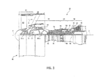
- Gas turbine engine 20 may be a two-spool turbofan that generally incorporates a fan section 22, a compressor section 24, a combustor section 26 and a turbine section 28.
- Alternative engines may include, for example, an augmenter section among other systems or features.
- fan section 22 can drive air along a bypass flow-path B while compressor section 24 can drive air for compression and communication into combustor section 26 then expansion through turbine section 28.
- turbofan gas turbine engine 20 depicted as a turbofan gas turbine engine 20 herein, it should be understood that the concepts described herein are not limited to use with turbofans as the teachings may be applied to other types of turbine engines including three-spool architectures.
- Gas turbine engine 20 may generally comprise a low speed spool 30 and a high speed spool 32 mounted for rotation about an engine central longitudinal axis A-A' relative to an engine static structure 36 via one or more bearing systems 38 (shown as bearing system 38-1 and bearing system 38-2 in FIG. 1 ). It should be understood that various bearing systems 38 at various locations may alternatively or additionally be provided, including for example, bearing system 38, bearing system 38-1, and bearing system 38-2.
- Low speed spool 30 may generally comprise an inner shaft 40 that interconnects a fan 42, a low pressure (or first) compressor section 44 (also referred to a low pressure compressor) and a low pressure (or first) turbine section 46.
- Inner shaft 40 may be connected to fan 42 through a geared architecture 48 that can drive fan 42 at a lower speed than low speed spool 30.
- Geared architecture 48 may comprise a gear assembly 60 enclosed within a gear housing 62.
- Gear assembly 60 couples inner shaft 40 to a rotating fan structure.
- High speed spool 32 may comprise an outer shaft 50 that interconnects a high pressure compressor (“HPC") 52 (e.g., a second compressor section) and high pressure (or second) turbine section 54.
- HPC high pressure compressor
- a combustor 56 may be located between HPC 52 and high pressure turbine 54.
- a mid-turbine frame 57 of engine static structure 36 may be located generally between high pressure turbine 54 and low pressure turbine 46.
- Mid-turbine frame 57 may support one or more bearing systems 38 in turbine section 28.
- Inner shaft 40 and outer shaft 50 may be concentric and rotate via bearing systems 38 about the engine central longitudinal axis A-A', which is collinear with their longitudinal axes.
- a "high pressure" compressor or turbine experiences a higher pressure than a corresponding "low pressure” compressor or turbine.
- the core airflow may be compressed by low pressure compressor 44 then HPC 52, mixed and burned with fuel in combustor 56, then expanded over high pressure turbine 54 and low pressure turbine 46.
- Mid-turbine frame 57 includes airfoils 59 which are in the core airflow path.
- Low pressure turbine 46, and high pressure turbine 54 rotationally drive the respective low speed spool 30 and high speed spool 32 in response to the expansion.
- Gas turbine engine 20 may be, for example, a high-bypass geared aircraft engine. In various embodiments, the bypass ratio of gas turbine engine 20 may be greater than about six (6). In various embodiments, the bypass ratio of gas turbine engine 20 may be greater than ten (10).
- geared architecture 48 may be an epicyclic gear train, such as a star gear system (sun gear in meshing engagement with a plurality of star gears supported by a carrier and in meshing engagement with a ring gear) or other gear system. Geared architecture 48 may have a gear reduction ratio of greater than about 2.3 and low pressure turbine 46 may have a pressure ratio that is greater than about 5. In various embodiments, the bypass ratio of gas turbine engine 20 is greater than about ten (10:1).
- the diameter of fan 42 may be significantly larger than that of the low pressure compressor 44, and the low pressure turbine 46 may have a pressure ratio that is greater than about (5:1). Low pressure turbine 46 pressure ratio may be measured prior to inlet of low pressure turbine 46 as related to the pressure at the outlet of low pressure turbine 46 prior to an exhaust nozzle. It should be understood, however, that the above parameters are exemplary of various embodiments of a suitable geared architecture engine and that the present disclosure contemplates other gas turbine engines including direct drive turbofans.
- the next generation of turbofan engines may be designed for higher efficiency which requires higher pressure ratios and higher temperatures in the HPC 52. These higher operating temperatures and pressure ratios may create operating environments that may cause thermal loads that are higher than the thermal loads which may shorten the endurance life of current components.
- HPC 52 may comprise alternating rows of rotating rotors and stationary stators.
- Stators may have a cantilevered configuration or a shrouded configuration. More specifically, stator may comprise a stator vane, a casing support and a hub support. In this regard, stator vane may be supported along an outer diameter by casing support and along an inner diameter hub support.
- a cantilevered stator may comprise a stator vane that is only retained and/or supported at the casing (e.g., an outer diameter).
- rotors may be configured to compress and spin a fluid flow.
- Stators may be configured to receive and straighten the fluid flow.
- the fluid flow discharged from the trailing edge of stators may be straightened (e.g., the flow may be directed in a substantially parallel path to the centerline of the engine and/or HPC) to increase and/or improve the efficiency of the engine and, more specifically, to achieve maximum and/or near maximum compression and efficiency when the straightened air is compressed and spun by rotor 64.
- Operating conditions in the aft stages of HPC 52 may be approximately 1400°F (approximately 760°C) or more.
- turbine blades and vanes are subject to a high external heat load that is very localized to the stagnation location which is where the hot combustion gases impinge on the airfoil.
- the showerhead region includes a hole located at a stagnation location along the leading edge of the blade, which is the location where the hot gas flow directly hits the airfoil.
- the showerhead region is prone to high cycle fatigue (HCF) failure which is typically directly dependent on the local metal temperature near the cooling holes.
- HCF high cycle fatigue
- showerhead cooling holes are cooling holes, often machined into a leading edge configured to at least partially offset that external high heat load.
- the systems and apparatus disclosed herein are configured to reduce the local temperature around the showerhead cooling holes. This may increase the high cycle fatigue life of the associated parts.
- a minimum ligament distance span 310 may be maintained between adjacent showerhead cooling holes. Maintaining the minimum ligament distance span 310 tends to reduce cracking on the turbine blades and vanes.
- a tightly packed high coverage showerhead hole layout 400 depicting an adjusted breakout shape of the showerhead cooling holes configured to increase the density of cooling hole coverage across the turbine blades and vanes in a stagnation location.
- a first row 405 of showerhead cooling holes may span in a radial direction of a blades and/or vanes and each showerhead cooling hole 406 may comprise a breakout shape with a diffusion angle that is greater in the ⁇ direction than in the ⁇ direction.
- the diffusion angle from a centerline B-B' in the ⁇ direction may be from about 8 to about 15 degrees while the diffusion of the hole in the ⁇ direction may be between about 0 and about 5 degrees.
- a second row 415 of showerhead cooling holes spanning a radial direction of a blades and/or a vane may comprise a breakout shape with a diffusion angle that is substantially equivalent in the ⁇ direction and in the ⁇ direction.
- the diffusion angle from a centerline B-B' of showerhead cooling hole 416 in the ⁇ direction may be from about 0 to about 5 degrees and the diffusion angle of the breakout of showerhead cooling hole 416 in the ⁇ direction may be between about 0 and about 5 degrees.
- a third row 425 of showerhead cooling holes spanning a radial direction of a blades and/or a vane may comprise a breakout shape with a diffusion angle that is substantially equivalent in the ⁇ direction and in the ⁇ direction.
- the diffusion angle from a centerline B-B' of showerhead cooling hole 426 in the ⁇ direction may be from about 0 to about 5 degrees and the diffusion angle of a breakout of showerhead cooling hole 426 in the ⁇ direction may be between about 0 and about 5 degrees.
- the showerhead cooling holes 416, 426 of second row 415 and third row 425, respectively, have minimum deflection angles in the ⁇ direction and in the ⁇ direction (e.g., in lateral directions).
- a minimum deflection angle as used herein may be between about 5 and 0 degrees.
- a forth row 435 of showerhead cooling holes 436 may span in a radial direction of a blades and/or vanes and each showerhead cooling hole 436 may comprise a breakout shape with a diffusion angle that is greater in the ⁇ direction than in the ⁇ direction.
- the diffusion angle from a centerline B-B' in the ⁇ direction may be from about 8 to about 15 degrees while the diffusion of the hole in the ⁇ direction may be between about 0 and about 5 degrees.
- Row 405 may be spaced a minimum ligament distance span 410 from second row 415.
- Second row 415 may be spaced a minimum ligament distance span 410 from both third row 425 and fourth row 435.
- Third row 425 may be spaced a minimum ligament distance span 410 from fourth row 435 and second row 415.
- the forward edge 408 of the breakout opening of showerhead cooling hole 406 may be offset from forward edge 418 of the breakout opening of showerhead cooling hole 416.
- the forward edge 408 of the breakout opening of showerhead cooling hole 406 may be substantially in the same axial alignment with a forward edge 428 of the breakout opening of showerhead cooling hole 426.
- the forward edge 418 of the breakout opening of showerhead cooling hole 416 may be offset from forward edge 428 of the breakout opening of showerhead cooling hole 426.
- the forward edge 418 of the breakout opening of showerhead cooling hole 416 may be substantially in the same axial alignment with a forward edge 438 of the breakout opening of showerhead cooling hole 436.
- the trailing edge 409 of the breakout opening of showerhead cooling hole 406 may be offset from trailing edge 419 of the breakout opening of showerhead cooling hole 416.
- the trailing edge 409 of the breakout opening of showerhead cooling hole 406 may be substantially in the same axial alignment with a trailing edge 429 of the breakout opening of showerhead cooling hole 426.
- the trailing edge 419 of the breakout opening of showerhead cooling hole 416 may be offset from a trailing edge 429 of the breakout opening of showerhead cooling hole 426.
- the trailing edge 419 of the breakout opening of showerhead cooling hole 416 may be substantially in the same axial alignment with a trailing edge 439 of the breakout opening of showerhead cooling hole 436.
- showerhead cooling hole 426 and showerhead cooling hole 416 may comprise substantially equivalent breakout shapes.
- showerhead cooling hole 426 and showerhead cooling hole 416 may comprise substantially equivalent breakout shapes.
- showerhead cooling hole 436 and showerhead cooling hole 406 may comprise substantially mirror image breakout shapes.
- showerhead cooling holes 406, 416, 426, and 426 may each comprise a substantially equivalent diffusion angle lambda ⁇ into the surface.
- diffusion angle ⁇ in the direction of the surface may be between about 8 and 15 degrees for each of showerhead cooling holes 406, 416, 426, and 426.
- rows 405, 415, 425 and 435 may be located closer together than prior art techniques (See FIG. 3 ). Closer packed rows yields additional total showerhead cooling hole density over an area. This may reduce the temperature of a zone of interest, such as a leading edge of a turbine blades and/or vanes. For instance, over 100 degrees of local temperature reduction proximate to the stagnation zone may be achieved utilizing the designs described herein.
- showerhead cooling hole coverage is increased as compared to traditional designs. Coverage as used herein may take into account a breakout of the hole, a pitch of the hole, and the locations of adjacent holes. Maximizing coverage increases the ability to achieve a cooling film on the external surface of the blade and/or vane.
- a layout 600 of 5 rows across is depicted.
- the geometry of the holes of layout 600 is similar the geometry of the holes of tightly packed high coverage showerhead hole layout 400 with an additional row 605 of holes between row 405 and second row 415.
- Row 605 alters the offset of row 405.
- row 405 may be spaced a minimum ligament distance span 410 from additional row 605.
- Additional row 605 may be spaced a minimum ligament distance span 410 from both row 405 and second row 415.
- the forward edge 408 of the breakout opening of showerhead cooling hole 405 may be offset from forward edge 608 of the breakout opening of showerhead cooling hole 605.
- the forward edge 408 of the breakout opening of showerhead cooling hole 405 may be substantially in the same axial alignment with a forward edge 418 of the breakout opening of showerhead cooling hole 416.
- the trailing edge 609 of the breakout opening of showerhead cooling hole 606 may be offset from trailing edge 419 of the breakout opening of showerhead cooling hole 416.
- the trailing edge 609 of the breakout opening of showerhead cooling hole 606 may be substantially in the same axial alignment with a trailing edge 429 of the breakout opening of showerhead cooling hole 426.
- a layout 700 of 3 rows across is depicted.
- the geometry of the holes of layout 700 is similar the geometry of the holes of layout 600 with additional row 605 and second row 415 removed.
- a layout 800 of 2 rows across is depicted.
- the geometry of the holes of layout 800 is similar the geometry of the holes of tightly packed high coverage showerhead hole layout 400 with second row 415, and 425 removed.
- the rows of holes may not span the entire radial span of a vane and/or a blade.
- the radial span of one or more rows may be a partial span.
- the radial span may be between 0-50 % of the radial direction of the blade or vane.
- a row of holes may comprise a conventional breakout shape, similar to the geometries depicted in FIG. 1 , and then vary to one of the hole breakout geometries depicted in FIGs. 4 , and/or FIGs. 6-8 .
- the cooling holes described herein satisfy minimum ligament spans that ensure a minimum distance exits between any part of one cooling hole and any part of the neighboring and/or adjacent cooling hole. This minimum ligament span limits how close the cooling holes are placed to one another.
- the internal cooling hole convection or "hA" in the cooling hole typically dominates the cooling of the showerhead region. Since the internal hole convection dominates, placing the cooling holes closer together is a powerful method to reduce the local metal temperature.
- showerhead cooling hole layouts described herein include minimal lateral cooling hole exit diffusion on the middle showerhead cooling hole rows and interior facing sides of outside rows. In this way, rows of cooling holes may be placed close together. Stated another way, the outer showerhead cooling hole rows substantially only include lateral cooling hole exit diffusion in the direction away from the other rows to again allow the rows to be placed as close together as possible.
- FIGs. 9A-9C illustrate isometric views of the tightly packed high coverage showerhead hole layout 400 (see FIG. 4 ) in accordance with various embodiments.
- Cooling air may be ejected from the cooling holes, such as showerhead cooling holes 406, 416, 426, 436, described herein.
- the cooling holes may be configured to produce a layer of cooling air that flows over the leading edge surface to protect the metal surface from too much exposure to the high temperature hot gas flow.
- the cooling air may be ejected in a radial direction of the blade or vane. A portion of the cooling air will thus migrate onto the leading edge surface of the blade or vane to provide a layer of cooling air.
- references to "various embodiments”, “one embodiment”, “an embodiment”, “an example embodiment”, etc. indicate that the embodiment described may include a particular feature, structure, or characteristic, but every embodiment may not necessarily include the particular feature, structure, or characteristic. Moreover, such phrases are not necessarily referring to the same embodiment. Further, when a particular feature, structure, or characteristic is described in connection with an embodiment, it is submitted that it is within the knowledge of one skilled in the art to affect such feature, structure, or characteristic in connection with other embodiments whether or not explicitly described. After reading the description, it will be apparent to one skilled in the relevant art(s) how to implement the disclosure in alternative embodiments.
Landscapes
- Engineering & Computer Science (AREA)
- Mechanical Engineering (AREA)
- General Engineering & Computer Science (AREA)
- Turbine Rotor Nozzle Sealing (AREA)
Abstract
Description
- The present disclosure relates generally to a gas turbine engine and more specifically to turbine blades and/or vanes exposed to high temperature.
- A gas turbine engine may include a turbine section with multiple rows or stages of stator vanes and rotor blades that interact or react with a high temperature gas flow to create mechanical power. In a gas turbine engine, the turbine rotor blades drive the compressor and an electric generator to generate electrical power. The efficiency of the engine can be increased by passing a higher temperature gas flow through the turbine. However, the turbine inlet temperature is limited to the vane and blade (airfoils) material properties and the cooling capabilities of these airfoils. The first stage airfoils are exposed to the highest temperature gas flow since these airfoils are located immediately downstream from the combustor. The temperature of the gas flow passing through the turbine progressively decreases as the rotor blade stages extract energy from the gas flow. The leading edge of the vane and blade airfoils is exposed to high temperature gas flow
- In various embodiments, a turbine showerhead cooling hole layout for a gas turbine component is disclosed. The turbine showerhead cooling hole layout may comprise a first pressure side / aft most row of radially disposed showerhead cooling holes, wherein the breakout of cooling holes of the first row comprise a greater deflection in a γ direction than in a δ direction. The turbine showerhead cooling hole layout may comprise a second row of radially disposed showerhead cooling holes, wherein the breakout of the cooling holes of the second row comprise about 0 to 5 degrees of deflection in the γ direction and the δ direction. The turbine showerhead cooling hole layout may comprise a fifth row (suction side / aft most) of radially disposed showerhead cooling holes, wherein the breakout of the cooling holes of the fifth row comprise a greater deflection in the δ direction than in the γ direction.
- In various embodiments, a turbine showerhead cooling hole layout for a gas turbine component is disclosed. The turbine showerhead cooling hole layout may comprise a first outer row of radially disposed showerhead cooling holes. The turbine showerhead cooling hole layout may comprise a first interior row of radially disposed showerhead cooling holes. The turbine showerhead cooling hole layout may comprise a second outer row of radially disposed showerhead cooling holes. The breakouts of the holes of the first outer row of radially disposed showerhead cooling holes, the first interior row of radially disposed showerhead cooling holes and the second outer row of radially disposed showerhead cooling holes may at least partially overlap along a lateral plane. The diffusion of the breakouts of the holes of the first outer row of radially disposed showerhead cooling holes, the first interior row of radially disposed showerhead cooling holes and the second outer row of radially disposed showerhead cooling holes may be directed away from adjacent rows.
- In various embodiments, a turbine showerhead cooling hole layout for a gas turbine component is disclosed. The turbine showerhead cooling hole layout may comprise a first outer row of radially disposed showerhead cooling holes. The turbine showerhead cooling hole layout may comprise a second outer row of radially disposed showerhead cooling holes. Diffusion of the breakouts of the holes of the first outer row of radially disposed showerhead cooling holes and the second outer row of radially disposed showerhead cooling holes are directed laterally away from adjacent rows. Diffusion of the breakouts of the holes of the first outer row of radially disposed showerhead cooling holes and the second outer row of radially disposed showerhead cooling holes are minimized in the lateral direction towards adjacent rows.
- A gas turbine component having a showerhead cooling hole layout is also disclosed. The Applicant reserves the right to claim this hole layout as such. The showerhead cooling hole layout comprises a first outer row of radially disposed showerhead cooling holes, a first interior row of radially disposed showerhead cooling holes, and a second outer row of radially disposed showerhead cooling holes. A breakout of the first outer row of radially disposed showerhead cooling holes, the first interior row of radially disposed showerhead cooling holes and the second outer row of radially disposed showerhead cooling holes, at least partially overlap along a lateral plane, and a first outer row diffusion angle of the breakout of the first outer row of radially disposed showerhead cooling holes, a first interior row diffusion angle of the breakout of the first interior row of radially disposed showerhead cooling holes and a second outer row diffusion angle of the breakout of the second outer row of radially disposed showerhead cooling holes are directed away from adjacent rows.
- The breakout of the first outer row of radially disposed showerhead cooling holes, the breakout of the first interior row of radially disposed showerhead cooling holes and the breakout of the second outer row of radially disposed showerhead cooling holes may include lateral cooling hole exit diffusion in a direction away from other rows.
- A diffusion angle may be between about 8 to about 15 degrees.
- A geometry of the breakout of the first outer row of radially disposed showerhead cooling holes, the first interior row of radially disposed showerhead cooling holes and the second outer row of radially disposed showerhead cooling holes may comprise a substantially equivalent diffusion in a λ direction.
- Another gas turbine component having a showerhead cooling hole layout is also disclosed. The Applicant reserves the right to claim this hole layout as such. The gas turbine component having a showerhead cooling hole layout comprises a first outer row of radially disposed showerhead cooling holes, and a second outer row of radially disposed showerhead cooling holes. A diffusion angle of a breakout of the first outer row of radially disposed showerhead cooling holes and a diffusion angle of a breakout of the second outer row of radially disposed showerhead cooling holes are directed laterally away from adjacent rows. The diffusion angle of the breakout of the first outer row of radially disposed showerhead cooling holes and the diffusion angle of the breakout of the second outer row of radially disposed showerhead cooling holes are minimized in a lateral direction towards adjacent rows.
- The forgoing features and elements may be combined in various combinations without exclusivity, unless expressly indicated herein otherwise. These features and elements as well as the operation of the disclosed embodiments will become more apparent in light of the following description and accompanying drawings.
- The subject matter of the present disclosure is particularly pointed out and distinctly claimed in the concluding portion of the specification. A more complete understanding of the present disclosure, however, may best be obtained by referring to the detailed description and claims when considered in connection with the drawing figures, wherein like numerals denote like elements.
-
FIG. 1 illustrates cross-sectional view of an exemplary gas turbine engine, in accordance with various embodiments; -
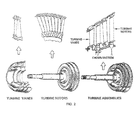
FIG. 2 illustrates a perspective view of turbine components in accordance with various embodiments; -
FIG. 3 illustrates a cross-sectional view of a prior art layout of showerhead cooling holes; -
FIG. 4 illustrates a cross-sectional view of a tightly packed high coverage showerhead hole scheme in accordance with various embodiments; -
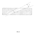
FIG. 5 illustrates a cross-sectional view of breakout of the diffusion into the surface of the holes of the tightly packed high coverage showerhead hole scheme ofFIG. 4 in accordance with various embodiments; -
FIG. 6 illustrates a cross-sectional view of a tightly packed high coverage showerhead hole scheme in accordance with various embodiments; -
FIG. 7 illustrates a cross-sectional view of a tightly packed high coverage showerhead hole scheme in accordance with various embodiments; -
FIG. 8 illustrates a cross-sectional view of a tightly packed high coverage showerhead hole scheme in accordance with various embodiments; and -
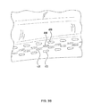
FIGs. 9A-9C illustrate isometric views of the tightly packed high coverage showerhead hole scheme ofFIG. 4 in accordance with various embodiments. - The detailed description of exemplary embodiments herein makes reference to the accompanying drawings, which show exemplary embodiments by way of illustration. While these exemplary embodiments are described in sufficient detail to enable those skilled in the art to practice the inventions, it should be understood that other embodiments may be realized and that logical changes and adaptations in design and construction may be made in accordance with this invention and the teachings herein. Thus, the detailed description herein is presented for purposes of illustration only and not of limitation. The scope of the invention is defined by the appended claims. For example, the steps recited in any of the method or process descriptions may be executed in any order and are not necessarily limited to the order presented. Furthermore, any reference to singular includes plural embodiments, and any reference to more than one component or step may include a singular embodiment or step. Also, any reference to attached, fixed, connected or the like may include permanent, removable, temporary, partial, full and/or any other possible attachment option. Additionally, any reference to without contact (or similar phrases) may also include reduced contact or minimal contact.
- Furthermore, any reference to singular includes plural embodiments, and any reference to more than one component or step may include a singular embodiment or step. Surface shading lines may be used throughout the figures to denote different parts but not necessarily to denote the same or different materials.
- As used herein, "aft" refers to the direction associated with the tail (e.g., the back end) of an aircraft, or generally, to the direction of exhaust of the gas turbine. As used herein, "forward" refers to the direction associated with the nose (e.g., the front end) of an aircraft, or generally, to the direction of flight or motion.
- In various embodiments and with reference to
FIG. 1 , a gas turbine engine 20 is provided. Gas turbine engine 20 may be a two-spool turbofan that generally incorporates a fan section 22, acompressor section 24, a combustor section 26 and aturbine section 28. Alternative engines may include, for example, an augmenter section among other systems or features. In operation, fan section 22 can drive air along a bypass flow-path B whilecompressor section 24 can drive air for compression and communication into combustor section 26 then expansion throughturbine section 28. Although depicted as a turbofan gas turbine engine 20 herein, it should be understood that the concepts described herein are not limited to use with turbofans as the teachings may be applied to other types of turbine engines including three-spool architectures. - Gas turbine engine 20 may generally comprise a
low speed spool 30 and a high speed spool 32 mounted for rotation about an engine central longitudinal axis A-A' relative to an enginestatic structure 36 via one or more bearing systems 38 (shown as bearing system 38-1 and bearing system 38-2 inFIG. 1 ). It should be understood that various bearingsystems 38 at various locations may alternatively or additionally be provided, including for example, bearingsystem 38, bearing system 38-1, and bearing system 38-2. -
Low speed spool 30 may generally comprise an inner shaft 40 that interconnects a fan 42, a low pressure (or first) compressor section 44 (also referred to a low pressure compressor) and a low pressure (or first) turbine section 46. Inner shaft 40 may be connected to fan 42 through a geared architecture 48 that can drive fan 42 at a lower speed thanlow speed spool 30. Geared architecture 48 may comprise a gear assembly 60 enclosed within a gear housing 62. Gear assembly 60 couples inner shaft 40 to a rotating fan structure. High speed spool 32 may comprise anouter shaft 50 that interconnects a high pressure compressor ("HPC") 52 (e.g., a second compressor section) and high pressure (or second)turbine section 54. A combustor 56 may be located between HPC 52 andhigh pressure turbine 54. A mid-turbine frame 57 of enginestatic structure 36 may be located generally betweenhigh pressure turbine 54 and low pressure turbine 46. Mid-turbine frame 57 may support one ormore bearing systems 38 inturbine section 28. Inner shaft 40 andouter shaft 50 may be concentric and rotate via bearingsystems 38 about the engine central longitudinal axis A-A', which is collinear with their longitudinal axes. As used herein, a "high pressure" compressor or turbine experiences a higher pressure than a corresponding "low pressure" compressor or turbine. - The core airflow may be compressed by low pressure compressor 44 then HPC 52, mixed and burned with fuel in combustor 56, then expanded over
high pressure turbine 54 and low pressure turbine 46. Mid-turbine frame 57 includes airfoils 59 which are in the core airflow path. Low pressure turbine 46, andhigh pressure turbine 54 rotationally drive the respectivelow speed spool 30 and high speed spool 32 in response to the expansion. - Gas turbine engine 20 may be, for example, a high-bypass geared aircraft engine. In various embodiments, the bypass ratio of gas turbine engine 20 may be greater than about six (6). In various embodiments, the bypass ratio of gas turbine engine 20 may be greater than ten (10). In various embodiments, geared architecture 48 may be an epicyclic gear train, such as a star gear system (sun gear in meshing engagement with a plurality of star gears supported by a carrier and in meshing engagement with a ring gear) or other gear system. Geared architecture 48 may have a gear reduction ratio of greater than about 2.3 and low pressure turbine 46 may have a pressure ratio that is greater than about 5. In various embodiments, the bypass ratio of gas turbine engine 20 is greater than about ten (10:1). In various embodiments, the diameter of fan 42 may be significantly larger than that of the low pressure compressor 44, and the low pressure turbine 46 may have a pressure ratio that is greater than about (5:1). Low pressure turbine 46 pressure ratio may be measured prior to inlet of low pressure turbine 46 as related to the pressure at the outlet of low pressure turbine 46 prior to an exhaust nozzle. It should be understood, however, that the above parameters are exemplary of various embodiments of a suitable geared architecture engine and that the present disclosure contemplates other gas turbine engines including direct drive turbofans.
- In various embodiments, the next generation of turbofan engines may be designed for higher efficiency which requires higher pressure ratios and higher temperatures in the HPC 52. These higher operating temperatures and pressure ratios may create operating environments that may cause thermal loads that are higher than the thermal loads which may shorten the endurance life of current components.
- In various embodiments, HPC 52 may comprise alternating rows of rotating rotors and stationary stators. Stators may have a cantilevered configuration or a shrouded configuration. More specifically, stator may comprise a stator vane, a casing support and a hub support. In this regard, stator vane may be supported along an outer diameter by casing support and along an inner diameter hub support. In contrast, a cantilevered stator may comprise a stator vane that is only retained and/or supported at the casing (e.g., an outer diameter).
- In various embodiments, rotors may be configured to compress and spin a fluid flow. Stators may be configured to receive and straighten the fluid flow. In operation, the fluid flow discharged from the trailing edge of stators may be straightened (e.g., the flow may be directed in a substantially parallel path to the centerline of the engine and/or HPC) to increase and/or improve the efficiency of the engine and, more specifically, to achieve maximum and/or near maximum compression and efficiency when the straightened air is compressed and spun by rotor 64.
- Operating conditions in the aft stages of HPC 52 may be approximately 1400°F (approximately 760°C) or more. As noted above and with reference to
FIG. 2 , turbine blades and vanes are subject to a high external heat load that is very localized to the stagnation location which is where the hot combustion gases impinge on the airfoil. The showerhead region includes a hole located at a stagnation location along the leading edge of the blade, which is the location where the hot gas flow directly hits the airfoil. The showerhead region is prone to high cycle fatigue (HCF) failure which is typically directly dependent on the local metal temperature near the cooling holes. Showerhead cooling holes are cooling holes, often machined into a leading edge configured to at least partially offset that external high heat load. - According to various embodiments, the systems and apparatus disclosed herein are configured to reduce the local temperature around the showerhead cooling holes. This may increase the high cycle fatigue life of the associated parts.
- Historically, with reference to prior art
FIG. 3 , a row of showerhead cooling holes, three across, comprising diffusion angles of their breakout shape along both the external surface in the delta "δ" and gamma "γ" directions away from a center line A-A' are depicted. A minimumligament distance span 310 may be maintained between adjacent showerhead cooling holes. Maintaining the minimumligament distance span 310 tends to reduce cracking on the turbine blades and vanes. - According to various embodiments and with reference to
FIG. 4 , a tightly packed high coverageshowerhead hole layout 400 depicting an adjusted breakout shape of the showerhead cooling holes configured to increase the density of cooling hole coverage across the turbine blades and vanes in a stagnation location. For instance, afirst row 405 of showerhead cooling holes may span in a radial direction of a blades and/or vanes and eachshowerhead cooling hole 406 may comprise a breakout shape with a diffusion angle that is greater in the γ direction than in the δ direction. For instance, the diffusion angle from a centerline B-B' in the γ direction may be from about 8 to about 15 degrees while the diffusion of the hole in the δ direction may be between about 0 and about 5 degrees. Asecond row 415 of showerhead cooling holes spanning a radial direction of a blades and/or a vane may comprise a breakout shape with a diffusion angle that is substantially equivalent in the γ direction and in the δ direction. For instance, the diffusion angle from a centerline B-B' ofshowerhead cooling hole 416 in the γ direction may be from about 0 to about 5 degrees and the diffusion angle of the breakout ofshowerhead cooling hole 416 in the δ direction may be between about 0 and about 5 degrees. - A
third row 425 of showerhead cooling holes spanning a radial direction of a blades and/or a vane may comprise a breakout shape with a diffusion angle that is substantially equivalent in the γ direction and in the δ direction. For instance, the diffusion angle from a centerline B-B' ofshowerhead cooling hole 426 in the γ direction may be from about 0 to about 5 degrees and the diffusion angle of a breakout ofshowerhead cooling hole 426 in the δ direction may be between about 0 and about 5 degrees. - The showerhead cooling holes 416, 426 of
second row 415 andthird row 425, respectively, have minimum deflection angles in the δ direction and in the γ direction (e.g., in lateral directions). A minimum deflection angle as used herein may be between about 5 and 0 degrees. - For instance, a
forth row 435 of showerhead cooling holes 436 may span in a radial direction of a blades and/or vanes and eachshowerhead cooling hole 436 may comprise a breakout shape with a diffusion angle that is greater in the δ direction than in the γ direction. For instance, the diffusion angle from a centerline B-B' in the δ direction may be from about 8 to about 15 degrees while the diffusion of the hole in the γ direction may be between about 0 and about 5 degrees. - Row 405 may be spaced a minimum
ligament distance span 410 fromsecond row 415.Second row 415 may be spaced a minimumligament distance span 410 from boththird row 425 andfourth row 435.Third row 425 may be spaced a minimumligament distance span 410 fromfourth row 435 andsecond row 415. Theforward edge 408 of the breakout opening ofshowerhead cooling hole 406 may be offset fromforward edge 418 of the breakout opening ofshowerhead cooling hole 416. Theforward edge 408 of the breakout opening ofshowerhead cooling hole 406 may be substantially in the same axial alignment with aforward edge 428 of the breakout opening ofshowerhead cooling hole 426. - The
forward edge 418 of the breakout opening ofshowerhead cooling hole 416 may be offset fromforward edge 428 of the breakout opening ofshowerhead cooling hole 426. Theforward edge 418 of the breakout opening ofshowerhead cooling hole 416 may be substantially in the same axial alignment with aforward edge 438 of the breakout opening ofshowerhead cooling hole 436. - The trailing
edge 409 of the breakout opening ofshowerhead cooling hole 406 may be offset from trailingedge 419 of the breakout opening ofshowerhead cooling hole 416. The trailingedge 409 of the breakout opening ofshowerhead cooling hole 406 may be substantially in the same axial alignment with a trailingedge 429 of the breakout opening ofshowerhead cooling hole 426. - The trailing
edge 419 of the breakout opening ofshowerhead cooling hole 416 may be offset from a trailingedge 429 of the breakout opening ofshowerhead cooling hole 426. The trailingedge 419 of the breakout opening ofshowerhead cooling hole 416 may be substantially in the same axial alignment with a trailingedge 439 of the breakout opening ofshowerhead cooling hole 436. -
Showerhead cooling hole 426 andshowerhead cooling hole 416 may comprise substantially equivalent breakout shapes.Showerhead cooling hole 426 andshowerhead cooling hole 416 may comprise substantially equivalent breakout shapes.Showerhead cooling hole 436 andshowerhead cooling hole 406 may comprise substantially mirror image breakout shapes. - According to various embodiments and with reference to
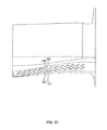
FIG. 5 , showerhead cooling holes 406, 416, 426, and 426 may each comprise a substantially equivalent diffusion angle lambda λ into the surface. For instance, diffusion angle λ in the direction of the surface may be between about 8 and 15 degrees for each of showerhead cooling holes 406, 416, 426, and 426. - Due to the varied breakout shapes of
rows FIG. 3 ). Closer packed rows yields additional total showerhead cooling hole density over an area. This may reduce the temperature of a zone of interest, such as a leading edge of a turbine blades and/or vanes. For instance, over 100 degrees of local temperature reduction proximate to the stagnation zone may be achieved utilizing the designs described herein. - According to various embodiments showerhead cooling hole coverage is increased as compared to traditional designs. Coverage as used herein may take into account a breakout of the hole, a pitch of the hole, and the locations of adjacent holes. Maximizing coverage increases the ability to achieve a cooling film on the external surface of the blade and/or vane.
- According to various embodiments and with reference to
FIG. 6 , alayout 600 of 5 rows across is depicted. The geometry of the holes oflayout 600 is similar the geometry of the holes of tightly packed high coverageshowerhead hole layout 400 with anadditional row 605 of holes betweenrow 405 andsecond row 415. Row 605 alters the offset ofrow 405. As depicted inFIG. 6 ,row 405 may be spaced a minimumligament distance span 410 fromadditional row 605.Additional row 605 may be spaced a minimumligament distance span 410 from bothrow 405 andsecond row 415. - The
forward edge 408 of the breakout opening ofshowerhead cooling hole 405 may be offset fromforward edge 608 of the breakout opening ofshowerhead cooling hole 605. Theforward edge 408 of the breakout opening ofshowerhead cooling hole 405 may be substantially in the same axial alignment with aforward edge 418 of the breakout opening ofshowerhead cooling hole 416. - The trailing
edge 609 of the breakout opening ofshowerhead cooling hole 606 may be offset from trailingedge 419 of the breakout opening ofshowerhead cooling hole 416. The trailingedge 609 of the breakout opening ofshowerhead cooling hole 606 may be substantially in the same axial alignment with a trailingedge 429 of the breakout opening ofshowerhead cooling hole 426. - According to various embodiments and with reference to
FIG. 7 , alayout 700 of 3 rows across is depicted. The geometry of the holes oflayout 700 is similar the geometry of the holes oflayout 600 withadditional row 605 andsecond row 415 removed. - According to various embodiments and with reference to
FIG. 8 , alayout 800 of 2 rows across is depicted. The geometry of the holes oflayout 800 is similar the geometry of the holes of tightly packed high coverageshowerhead hole layout 400 withsecond row - According to various embodiments the rows of holes may not span the entire radial span of a vane and/or a blade. For instance the radial span of one or more rows may be a partial span. The radial span may be between 0-50 % of the radial direction of the blade or vane. The geometry of the shape of a breakout of holes in a row along a radial span of holes. For instance, towards the distal end (e.g., away from an attachment surface) of a row in the radial direction a row of holes may comprise a conventional breakout shape, similar to the geometries depicted in
FIG. 1 , and then vary to one of the hole breakout geometries depicted inFIGs. 4 , and/orFIGs. 6-8 . - According to various embodiments, the cooling holes described herein (e.g., showerhead cooling holes 406, 416, 426, 436, 606) satisfy minimum ligament spans that ensure a minimum distance exits between any part of one cooling hole and any part of the neighboring and/or adjacent cooling hole. This minimum ligament span limits how close the cooling holes are placed to one another. The internal cooling hole convection or "hA" in the cooling hole typically dominates the cooling of the showerhead region. Since the internal hole convection dominates, placing the cooling holes closer together is a powerful method to reduce the local metal temperature.
- According to various embodiments, showerhead cooling hole layouts described herein include minimal lateral cooling hole exit diffusion on the middle showerhead cooling hole rows and interior facing sides of outside rows. In this way, rows of cooling holes may be placed close together. Stated another way, the outer showerhead cooling hole rows substantially only include lateral cooling hole exit diffusion in the direction away from the other rows to again allow the rows to be placed as close together as possible.
- Local metal temperature is reduced by packing the showerhead hole rows close together, which maximizes the local cooling ability. The diffusion of the shaped cooling holes is catered to pack a very dense array of cooling holes into a small area near the stagnation zone. These cooling holes maintain very large footprints which increase the coverage in an effort to maximize the film cooling as well.
- The technology disclosed herein implements a cooling hole scheme that can locally counteract the external heat load in a highly efficient manner.
FIGs. 9A-9C illustrate isometric views of the tightly packed high coverage showerhead hole layout 400 (seeFIG. 4 ) in accordance with various embodiments. - Cooling air may be ejected from the cooling holes, such as showerhead cooling holes 406, 416, 426, 436, described herein. The cooling holes may be configured to produce a layer of cooling air that flows over the leading edge surface to protect the metal surface from too much exposure to the high temperature hot gas flow. The cooling air may be ejected in a radial direction of the blade or vane. A portion of the cooling air will thus migrate onto the leading edge surface of the blade or vane to provide a layer of cooling air.
- Benefits, other advantages and solutions to problems have been described herein with regard to specific embodiments. Furthermore, the connecting lines shown in the various figures contained herein are intended to represent exemplary functional relationships and/or physical couplings between the various elements. It should be noted that many alternative or additional functional relationships or physical connections may be present in a practical system. However, the benefits, advantages, solutions to problems, and any elements that may cause any benefit, advantage, or solution to occur or become more pronounced are not to be construed as critical, required, or essential features or elements of the inventions. The scope of the inventions is accordingly to be limited by nothing other than the appended claims, in which reference to an element in the singular is not intended to mean "one and only one" unless explicitly so stated, but rather "one or more." Moreover, where a phrase similar to "at least one of A, B, or C" is used in the claims, it is intended that the phrase be interpreted to mean that A alone may be present in an embodiment, B alone may be present in an embodiment, C alone may be present in an embodiment, or that any combination of the elements A, B and C may be present in a single embodiment; for example, A and B, A and C, B and C, or A and B and C.
- The foregoing features and elements may be combined in various combinations without exclusivity, unless expressly indicated otherwise. These features and elements as well as the operation thereof will become more apparent in light of the following description and the accompanying drawings. It should be understood, however, the following description and drawings are intended to be exemplary in nature and nonlimiting.
- Systems, methods and apparatus are provided herein. In the detailed description herein, references to "various embodiments", "one embodiment", "an embodiment", "an example embodiment", etc., indicate that the embodiment described may include a particular feature, structure, or characteristic, but every embodiment may not necessarily include the particular feature, structure, or characteristic. Moreover, such phrases are not necessarily referring to the same embodiment. Further, when a particular feature, structure, or characteristic is described in connection with an embodiment, it is submitted that it is within the knowledge of one skilled in the art to affect such feature, structure, or characteristic in connection with other embodiments whether or not explicitly described. After reading the description, it will be apparent to one skilled in the relevant art(s) how to implement the disclosure in alternative embodiments.
- Furthermore, no element, component, or method step in the present disclosure is intended to be dedicated to the public regardless of whether the element, component, or method step is explicitly recited in the claims. No claim element herein is to be construed under the provisions of 35 U.S.C. 112(f), unless the element is expressly recited using the phrase "means for." As used herein, the terms "comprises", "comprising", or any other variation thereof, are intended to cover a non-exclusive inclusion, such that a process, method, article, or apparatus that comprises a list of elements does not include only those elements but may include other elements not expressly listed or inherent to such process, method, article, or apparatus.
Claims (15)
- A gas turbine component having a showerhead cooling hole layout (400; 600; 700; 800), comprising:a pressure side row (405) of radially disposed showerhead cooling holes (406),wherein a breakout of the pressure side row (405) of radially disposed showerhead cooling holes (406) comprise a greater deflection in a γ direction than in a δ direction, where γ and δ are lateral directions;a second row (425) of radially disposed showerhead cooling holes (426), wherein a breakout of the second row (425) of radially disposed showerhead cooling holes (426) comprise about 0 to 5 degrees of deflection in the γ direction and the δ direction; anda suction side row (435) of radially disposed showerhead cooling holes (436),
wherein a breakout of the suction side row (435) of radially disposed showerhead cooling holes (436) comprise a greater deflection in the δ direction than in the γ direction. - The gas turbine component having the showerhead cooling hole layout (400; 600; 700; 800) of claim 1, further comprising a third row (415) of radially disposed showerhead cooling holes (416), wherein the breakout of the third row (415) of radially disposed showerhead cooling holes (416) comprise about 0 to 5 degrees of deflection in the γ direction and the δ direction.
- The gas turbine component having the showerhead cooling hole layout (400; 600; 700; 800) of claim 2, further comprising a fourth row (605) of radially disposed showerhead cooling holes (606), wherein the breakout of the fourth row (605) of radially disposed showerhead cooling holes (606) comprise about 0 to 5 degrees of deflection in the γ direction and the δ direction.
- The gas turbine component having the showerhead cooling hole layout (400; 600; 700; 800) of any preceding claim, wherein the breakout of the pressure side row (405) of radially disposed showerhead cooling holes (406) and the breakout of the suction side row (435) of radially disposed showerhead cooling holes (236) include lateral cooling hole exit diffusion in the direction away from other rows (415, 425, 605).
- The gas turbine component having the showerhead cooling hole layout (400; 600; 700; 800) of any preceding claim, wherein the turbine showerhead cooling hole layout (400; 600; 700; 800) is disposed on a leading edge of at least one of a turbine blade or a turbine vane.
- The gas turbine component having the showerhead cooling hole layout (400; 600; 700; 800) of any preceding claim, wherein a minimum ligament distance (410), which limits how close showerhead cooling holes (406, 416, 426, 436, 606) are placed to one another, exists between any part of a radially disposed showerhead cooling hole (406, 416, 426, 436, 606) and any part of a neighboring radially disposed showerhead cooling hole (406, 416, 426, 436, 606).
- The gas turbine component having the showerhead cooling hole layout (400; 600; 700; 800) of any preceding claim, wherein a diffusion angle of the breakout of the pressure side row (405) of radially disposed showerhead cooling holes (406) from a centerline (B) in the γ direction is from about 8 to about 15 degrees, wherein a diffusion angle of the breakout of the pressure side row (405) of radially disposed showerhead cooling holes (406) in the δ direction is between about 0 and about 5 degrees.
- The gas turbine component having the showerhead cooling hole layout (400; 600; 700; 800) of any preceding claim, wherein a diffusion angle of the breakout of the suction side row (435) of radially disposed showerhead cooling holes (436) from a centerline (B) in the δ direction is from about 8 to about 15 degrees, wherein a diffusion angle of the breakout of the suction side row (435) of radially disposed showerhead cooling holes (436) in the γ direction is between about 0 and about 5 degrees.
- The gas turbine component having the showerhead cooling hole layout (400; 600; 700; 800) of any preceding claim, wherein a geometry of the breakout of the pressure side row (405) of radially disposed showerhead cooling holes (405) and a geometry of the breakout of the suction side row (435) of radially disposed showerhead cooling holes (436) are mirror images.
- The gas turbine component having the showerhead cooling hole layout (400; 600; 700; 800) of any preceding claim, wherein a geometry of the breakout of the pressure side row (405) of radially disposed showerhead cooling holes (406), a geometry of the breakout of the second row (425) of radially disposed showerhead cooling holes (426) and a geometry of the breakout of the suction side row (435) of radially disposed showerhead cooling holes (436) comprise a substantially equivalent diffusion in a λ direction.
- The gas turbine component having the showerhead cooling hole layout (400; 600; 700; 800) of any preceding claim, wherein a forward edge (408) of the breakout of the pressure side row (405) of radially disposed showerhead cooling holes (406) is offset from a forward edge (418, 428, 438, 608) of the breakout of a radially disposed showerhead cooling hole (416, 426, 436, 606) of an adjacent row (415, 425, 435, 605).
- The gas turbine component having the showerhead cooling hole (400; 600; 700; 800) layout of any preceding claim, wherein a trailing edge (409) of the breakout of the pressure side row (405) of radially disposed showerhead cooling holes (406) is offset from a trailing edge (419, 429, 439, 609) of the breakout of a radially disposed showerhead cooling hole (416, 426, 436, 606) of an adjacent row (415, 425, 435, 605).
- The gas turbine component having the showerhead cooling hole layout (400; 600; 700; 800) of any preceding claim, wherein a forward edge (418, 428, 438, 608) of the breakout of the pressures side row (405) of radially disposed showerhead cooling holes (406) is substantially in lateral alignment with a forward edge (418, 428, 438, 608) of the breakout of the suction side row (435) of radially disposed showerhead cooling holes (436).
- The gas turbine component having the showerhead cooling hole layout (400; 600; 700; 800) of any preceding claim, wherein a trailing edge (409) of the breakout of the pressures side row (405) of radially disposed showerhead cooling holes (406) is substantially in lateral alignment with a trailing edge (439) of the breakout of the suction side row (435) of radially disposed showerhead cooling holes (436).
- The gas turbine component having the showerhead cooling hole layout (400; 600; 700; 800) of any preceding claim, wherein at least one of the pressure side row (405) of radially disposed showerhead cooling holes (406), the second row (425) of radially disposed showerhead cooling holes (426), or the third row (415) of radially disposed showerhead cooling holes (416), span a partial length of a full length of at least one of a/the blade or a/the vane of a/the turbine.
Applications Claiming Priority (1)
| Application Number | Priority Date | Filing Date | Title |
|---|---|---|---|
| US201462037955P | 2014-08-15 | 2014-08-15 |
Publications (2)
| Publication Number | Publication Date |
|---|---|
| EP2987954A1 true EP2987954A1 (en) | 2016-02-24 |
| EP2987954B1 EP2987954B1 (en) | 2017-08-30 |
Family
ID=53365910
Family Applications (1)
| Application Number | Title | Priority Date | Filing Date |
|---|---|---|---|
| EP15171188.4A Active EP2987954B1 (en) | 2014-08-15 | 2015-06-09 | Gas turbine component with showerhead cooling hole layout |
Country Status (2)
| Country | Link |
|---|---|
| US (1) | US10041356B2 (en) |
| EP (1) | EP2987954B1 (en) |
Cited By (2)
| Publication number | Priority date | Publication date | Assignee | Title |
|---|---|---|---|---|
| EP3061911A1 (en) * | 2015-02-24 | 2016-08-31 | General Electric Company | Engine component |
| EP3088670A1 (en) * | 2015-04-27 | 2016-11-02 | United Technologies Corporation | Film cooled component and corresponding film cooling system |
Families Citing this family (6)
| Publication number | Priority date | Publication date | Assignee | Title |
|---|---|---|---|---|
| US11156117B2 (en) | 2016-04-25 | 2021-10-26 | Raytheon Technologies Corporation | Seal arc segment with sloped circumferential sides |
| US10443401B2 (en) * | 2016-09-02 | 2019-10-15 | United Technologies Corporation | Cooled turbine vane with alternately orientated film cooling hole rows |
| US10641102B2 (en) * | 2017-09-01 | 2020-05-05 | United Technologies Corporation | Turbine vane cluster including enhanced vane cooling |
| US10760431B2 (en) * | 2017-09-07 | 2020-09-01 | General Electric Company | Component for a turbine engine with a cooling hole |
| US11359494B2 (en) * | 2019-08-06 | 2022-06-14 | General Electric Company | Engine component with cooling hole |
| CN114439556B (en) * | 2022-01-24 | 2023-09-12 | 天津国能津能热电有限公司 | Turbine rotating speed probe cooling support |
Citations (5)
| Publication number | Priority date | Publication date | Assignee | Title |
|---|---|---|---|---|
| US5688104A (en) * | 1993-11-24 | 1997-11-18 | United Technologies Corporation | Airfoil having expanded wall portions to accommodate film cooling holes |
| EP1079071A2 (en) * | 1999-08-23 | 2001-02-28 | General Electric Company | Turbine blade with preferentially cooled trailing edge pressure wall |
| US20060073015A1 (en) * | 2004-10-01 | 2006-04-06 | Alstom Technology Ltd. | Gas turbine airfoil film cooling hole |
| EP1645721A2 (en) * | 2004-10-04 | 2006-04-12 | ALSTOM Technology Ltd | Gas turbine airfoil with leading edge cooling |
| EP2075410A2 (en) * | 2007-12-28 | 2009-07-01 | General Electric Company | Method for forming cooling holes and turbine airfoil with hybrid-formed cooling holes |
Family Cites Families (9)
| Publication number | Priority date | Publication date | Assignee | Title |
|---|---|---|---|---|
| US5486093A (en) * | 1993-09-08 | 1996-01-23 | United Technologies Corporation | Leading edge cooling of turbine airfoils |
| EP0945593B1 (en) * | 1998-03-23 | 2003-05-07 | ALSTOM (Switzerland) Ltd | Film-cooling hole |
| US6164912A (en) * | 1998-12-21 | 2000-12-26 | United Technologies Corporation | Hollow airfoil for a gas turbine engine |
| DE502004003477D1 (en) * | 2004-07-05 | 2007-05-24 | Siemens Ag | Film-cooled turbine blade |
| US7246992B2 (en) * | 2005-01-28 | 2007-07-24 | General Electric Company | High efficiency fan cooling holes for turbine airfoil |
| US7377743B2 (en) * | 2005-12-19 | 2008-05-27 | General Electric Company | Countercooled turbine nozzle |
| US7789626B1 (en) * | 2007-05-31 | 2010-09-07 | Florida Turbine Technologies, Inc. | Turbine blade with showerhead film cooling holes |
| US8733111B2 (en) * | 2012-02-15 | 2014-05-27 | United Technologies Corporation | Cooling hole with asymmetric diffuser |
| US9080451B2 (en) * | 2012-06-28 | 2015-07-14 | General Electric Company | Airfoil |
-
2015
- 2015-06-08 US US14/733,686 patent/US10041356B2/en active Active
- 2015-06-09 EP EP15171188.4A patent/EP2987954B1/en active Active
Patent Citations (5)
| Publication number | Priority date | Publication date | Assignee | Title |
|---|---|---|---|---|
| US5688104A (en) * | 1993-11-24 | 1997-11-18 | United Technologies Corporation | Airfoil having expanded wall portions to accommodate film cooling holes |
| EP1079071A2 (en) * | 1999-08-23 | 2001-02-28 | General Electric Company | Turbine blade with preferentially cooled trailing edge pressure wall |
| US20060073015A1 (en) * | 2004-10-01 | 2006-04-06 | Alstom Technology Ltd. | Gas turbine airfoil film cooling hole |
| EP1645721A2 (en) * | 2004-10-04 | 2006-04-12 | ALSTOM Technology Ltd | Gas turbine airfoil with leading edge cooling |
| EP2075410A2 (en) * | 2007-12-28 | 2009-07-01 | General Electric Company | Method for forming cooling holes and turbine airfoil with hybrid-formed cooling holes |
Cited By (3)
| Publication number | Priority date | Publication date | Assignee | Title |
|---|---|---|---|---|
| EP3061911A1 (en) * | 2015-02-24 | 2016-08-31 | General Electric Company | Engine component |
| EP3088670A1 (en) * | 2015-04-27 | 2016-11-02 | United Technologies Corporation | Film cooled component and corresponding film cooling system |
| US10208602B2 (en) | 2015-04-27 | 2019-02-19 | United Technologies Corporation | Asymmetric diffuser opening for film cooling holes |
Also Published As
| Publication number | Publication date |
|---|---|
| US20160047250A1 (en) | 2016-02-18 |
| US10041356B2 (en) | 2018-08-07 |
| EP2987954B1 (en) | 2017-08-30 |
Similar Documents
| Publication | Publication Date | Title |
|---|---|---|
| EP2987954B1 (en) | Gas turbine component with showerhead cooling hole layout | |
| US10208602B2 (en) | Asymmetric diffuser opening for film cooling holes | |
| EP3020923B1 (en) | Cooled turbine blade | |
| US9976423B2 (en) | Airfoil showerhead pattern apparatus and system | |
| EP2877709B1 (en) | Blade outer air seal for a gas turbine engine | |
| US9803489B2 (en) | Low loss baffled serpentine turns | |
| EP3421723A2 (en) | Airfoils and corresponding method of manufacturing | |
| EP3477058A1 (en) | Airfoil cooling circuit | |
| US9963982B2 (en) | Casting optimized to improve suction side cooling shaped hole performance | |
| EP3382147B1 (en) | Asymmetric vane assembly | |
| EP3412870A1 (en) | Turbine blade tip comprising oblong purge holes | |
| EP3597861B1 (en) | Contact coupled vane airfoil segments | |
| EP3026217B1 (en) | Turbine rotor or stator segmented sideplates with anti-rotation | |
| US11371372B2 (en) | Beveled coverplate | |
| US20160333701A1 (en) | Airfoil impingement cavity | |
| EP3453829A1 (en) | Inlet guide vane having a varied trailing edge geometry | |
| US20160237850A1 (en) | Systems and methods for vane cooling | |
| US20180306038A1 (en) | Airfoil impingement cavity | |
| EP3043031B1 (en) | Vane assembly, vane set, and method of manufacturing a vane assembly | |
| EP3470685A1 (en) | Gap closing wearliner | |
| US20160348510A1 (en) | Disk lug cooling flow trenches | |
| US20170022823A1 (en) | Turbine rotors including turbine blades having turbulator-cooled tip pockets |
Legal Events
| Date | Code | Title | Description |
|---|---|---|---|
| PUAI | Public reference made under article 153(3) epc to a published international application that has entered the european phase |
Free format text: ORIGINAL CODE: 0009012 |
|
| AK | Designated contracting states |
Kind code of ref document: A1 Designated state(s): AL AT BE BG CH CY CZ DE DK EE ES FI FR GB GR HR HU IE IS IT LI LT LU LV MC MK MT NL NO PL PT RO RS SE SI SK SM TR |
|
| AX | Request for extension of the european patent |
Extension state: BA ME |
|
| 17P | Request for examination filed |
Effective date: 20160824 |
|
| RBV | Designated contracting states (corrected) |
Designated state(s): AL AT BE BG CH CY CZ DE DK EE ES FI FR GB GR HR HU IE IS IT LI LT LU LV MC MK MT NL NO PL PT RO RS SE SI SK SM TR |
|
| RAP1 | Party data changed (applicant data changed or rights of an application transferred) |
Owner name: UNITED TECHNOLOGIES CORPORATION |
|
| GRAP | Despatch of communication of intention to grant a patent |
Free format text: ORIGINAL CODE: EPIDOSNIGR1 |
|
| STAA | Information on the status of an ep patent application or granted ep patent |
Free format text: STATUS: GRANT OF PATENT IS INTENDED |
|
| RIC1 | Information provided on ipc code assigned before grant |
Ipc: F01D 5/18 20060101AFI20170303BHEP Ipc: F01D 9/04 20060101ALI20170303BHEP Ipc: F01D 25/12 20060101ALI20170303BHEP |
|
| INTG | Intention to grant announced |
Effective date: 20170327 |
|
| RIN1 | Information on inventor provided before grant (corrected) |
Inventor name: LEWIS, SCOTT D. |
|
| GRAS | Grant fee paid |
Free format text: ORIGINAL CODE: EPIDOSNIGR3 |
|
| GRAA | (expected) grant |
Free format text: ORIGINAL CODE: 0009210 |
|
| STAA | Information on the status of an ep patent application or granted ep patent |
Free format text: STATUS: THE PATENT HAS BEEN GRANTED |
|
| AK | Designated contracting states |
Kind code of ref document: B1 Designated state(s): AL AT BE BG CH CY CZ DE DK EE ES FI FR GB GR HR HU IE IS IT LI LT LU LV MC MK MT NL NO PL PT RO RS SE SI SK SM TR |
|
| REG | Reference to a national code |
Ref country code: GB Ref legal event code: FG4D |
|
| REG | Reference to a national code |
Ref country code: CH Ref legal event code: EP |
|
| REG | Reference to a national code |
Ref country code: AT Ref legal event code: REF Ref document number: 923761 Country of ref document: AT Kind code of ref document: T Effective date: 20170915 |
|
| REG | Reference to a national code |
Ref country code: IE Ref legal event code: FG4D |
|
| REG | Reference to a national code |
Ref country code: DE Ref legal event code: R096 Ref document number: 602015004387 Country of ref document: DE |
|
| REG | Reference to a national code |
Ref country code: NL Ref legal event code: MP Effective date: 20170830 |
|
| REG | Reference to a national code |
Ref country code: LT Ref legal event code: MG4D |
|
| REG | Reference to a national code |
Ref country code: AT Ref legal event code: MK05 Ref document number: 923761 Country of ref document: AT Kind code of ref document: T Effective date: 20170830 |
|
| PG25 | Lapsed in a contracting state [announced via postgrant information from national office to epo] |
Ref country code: AT Free format text: LAPSE BECAUSE OF FAILURE TO SUBMIT A TRANSLATION OF THE DESCRIPTION OR TO PAY THE FEE WITHIN THE PRESCRIBED TIME-LIMIT Effective date: 20170830 Ref country code: NO Free format text: LAPSE BECAUSE OF FAILURE TO SUBMIT A TRANSLATION OF THE DESCRIPTION OR TO PAY THE FEE WITHIN THE PRESCRIBED TIME-LIMIT Effective date: 20171130 Ref country code: SE Free format text: LAPSE BECAUSE OF FAILURE TO SUBMIT A TRANSLATION OF THE DESCRIPTION OR TO PAY THE FEE WITHIN THE PRESCRIBED TIME-LIMIT Effective date: 20170830 Ref country code: FI Free format text: LAPSE BECAUSE OF FAILURE TO SUBMIT A TRANSLATION OF THE DESCRIPTION OR TO PAY THE FEE WITHIN THE PRESCRIBED TIME-LIMIT Effective date: 20170830 Ref country code: HR Free format text: LAPSE BECAUSE OF FAILURE TO SUBMIT A TRANSLATION OF THE DESCRIPTION OR TO PAY THE FEE WITHIN THE PRESCRIBED TIME-LIMIT Effective date: 20170830 Ref country code: LT Free format text: LAPSE BECAUSE OF FAILURE TO SUBMIT A TRANSLATION OF THE DESCRIPTION OR TO PAY THE FEE WITHIN THE PRESCRIBED TIME-LIMIT Effective date: 20170830 |
|
| PG25 | Lapsed in a contracting state [announced via postgrant information from national office to epo] |
Ref country code: GR Free format text: LAPSE BECAUSE OF FAILURE TO SUBMIT A TRANSLATION OF THE DESCRIPTION OR TO PAY THE FEE WITHIN THE PRESCRIBED TIME-LIMIT Effective date: 20171201 Ref country code: IS Free format text: LAPSE BECAUSE OF FAILURE TO SUBMIT A TRANSLATION OF THE DESCRIPTION OR TO PAY THE FEE WITHIN THE PRESCRIBED TIME-LIMIT Effective date: 20171230 Ref country code: ES Free format text: LAPSE BECAUSE OF FAILURE TO SUBMIT A TRANSLATION OF THE DESCRIPTION OR TO PAY THE FEE WITHIN THE PRESCRIBED TIME-LIMIT Effective date: 20170830 Ref country code: BG Free format text: LAPSE BECAUSE OF FAILURE TO SUBMIT A TRANSLATION OF THE DESCRIPTION OR TO PAY THE FEE WITHIN THE PRESCRIBED TIME-LIMIT Effective date: 20171130 Ref country code: LV Free format text: LAPSE BECAUSE OF FAILURE TO SUBMIT A TRANSLATION OF THE DESCRIPTION OR TO PAY THE FEE WITHIN THE PRESCRIBED TIME-LIMIT Effective date: 20170830 Ref country code: RS Free format text: LAPSE BECAUSE OF FAILURE TO SUBMIT A TRANSLATION OF THE DESCRIPTION OR TO PAY THE FEE WITHIN THE PRESCRIBED TIME-LIMIT Effective date: 20170830 |
|
| PG25 | Lapsed in a contracting state [announced via postgrant information from national office to epo] |
Ref country code: NL Free format text: LAPSE BECAUSE OF FAILURE TO SUBMIT A TRANSLATION OF THE DESCRIPTION OR TO PAY THE FEE WITHIN THE PRESCRIBED TIME-LIMIT Effective date: 20170830 |
|
| PG25 | Lapsed in a contracting state [announced via postgrant information from national office to epo] |
Ref country code: CZ Free format text: LAPSE BECAUSE OF FAILURE TO SUBMIT A TRANSLATION OF THE DESCRIPTION OR TO PAY THE FEE WITHIN THE PRESCRIBED TIME-LIMIT Effective date: 20170830 Ref country code: RO Free format text: LAPSE BECAUSE OF FAILURE TO SUBMIT A TRANSLATION OF THE DESCRIPTION OR TO PAY THE FEE WITHIN THE PRESCRIBED TIME-LIMIT Effective date: 20170830 Ref country code: PL Free format text: LAPSE BECAUSE OF FAILURE TO SUBMIT A TRANSLATION OF THE DESCRIPTION OR TO PAY THE FEE WITHIN THE PRESCRIBED TIME-LIMIT Effective date: 20170830 Ref country code: DK Free format text: LAPSE BECAUSE OF FAILURE TO SUBMIT A TRANSLATION OF THE DESCRIPTION OR TO PAY THE FEE WITHIN THE PRESCRIBED TIME-LIMIT Effective date: 20170830 |
|
| PG25 | Lapsed in a contracting state [announced via postgrant information from national office to epo] |
Ref country code: IT Free format text: LAPSE BECAUSE OF FAILURE TO SUBMIT A TRANSLATION OF THE DESCRIPTION OR TO PAY THE FEE WITHIN THE PRESCRIBED TIME-LIMIT Effective date: 20170830 Ref country code: EE Free format text: LAPSE BECAUSE OF FAILURE TO SUBMIT A TRANSLATION OF THE DESCRIPTION OR TO PAY THE FEE WITHIN THE PRESCRIBED TIME-LIMIT Effective date: 20170830 Ref country code: SM Free format text: LAPSE BECAUSE OF FAILURE TO SUBMIT A TRANSLATION OF THE DESCRIPTION OR TO PAY THE FEE WITHIN THE PRESCRIBED TIME-LIMIT Effective date: 20170830 Ref country code: SK Free format text: LAPSE BECAUSE OF FAILURE TO SUBMIT A TRANSLATION OF THE DESCRIPTION OR TO PAY THE FEE WITHIN THE PRESCRIBED TIME-LIMIT Effective date: 20170830 |
|
| REG | Reference to a national code |
Ref country code: DE Ref legal event code: R097 Ref document number: 602015004387 Country of ref document: DE |
|
| REG | Reference to a national code |
Ref country code: FR Ref legal event code: PLFP Year of fee payment: 4 |
|
| PLBE | No opposition filed within time limit |
Free format text: ORIGINAL CODE: 0009261 |
|
| STAA | Information on the status of an ep patent application or granted ep patent |
Free format text: STATUS: NO OPPOSITION FILED WITHIN TIME LIMIT |
|
| 26N | No opposition filed |
Effective date: 20180531 |
|
| PG25 | Lapsed in a contracting state [announced via postgrant information from national office to epo] |
Ref country code: SI Free format text: LAPSE BECAUSE OF FAILURE TO SUBMIT A TRANSLATION OF THE DESCRIPTION OR TO PAY THE FEE WITHIN THE PRESCRIBED TIME-LIMIT Effective date: 20170830 |
|
| REG | Reference to a national code |
Ref country code: CH Ref legal event code: PL |
|
| REG | Reference to a national code |
Ref country code: BE Ref legal event code: MM Effective date: 20180630 |
|
| REG | Reference to a national code |
Ref country code: IE Ref legal event code: MM4A |
|
| PG25 | Lapsed in a contracting state [announced via postgrant information from national office to epo] |
Ref country code: MC Free format text: LAPSE BECAUSE OF FAILURE TO SUBMIT A TRANSLATION OF THE DESCRIPTION OR TO PAY THE FEE WITHIN THE PRESCRIBED TIME-LIMIT Effective date: 20170830 Ref country code: LU Free format text: LAPSE BECAUSE OF NON-PAYMENT OF DUE FEES Effective date: 20180609 |
|
| PG25 | Lapsed in a contracting state [announced via postgrant information from national office to epo] |
Ref country code: CH Free format text: LAPSE BECAUSE OF NON-PAYMENT OF DUE FEES Effective date: 20180630 Ref country code: IE Free format text: LAPSE BECAUSE OF NON-PAYMENT OF DUE FEES Effective date: 20180609 Ref country code: LI Free format text: LAPSE BECAUSE OF NON-PAYMENT OF DUE FEES Effective date: 20180630 |
|
| PG25 | Lapsed in a contracting state [announced via postgrant information from national office to epo] |
Ref country code: BE Free format text: LAPSE BECAUSE OF NON-PAYMENT OF DUE FEES Effective date: 20180630 |
|
| PG25 | Lapsed in a contracting state [announced via postgrant information from national office to epo] |
Ref country code: MT Free format text: LAPSE BECAUSE OF NON-PAYMENT OF DUE FEES Effective date: 20180609 |
|
| PG25 | Lapsed in a contracting state [announced via postgrant information from national office to epo] |
Ref country code: TR Free format text: LAPSE BECAUSE OF FAILURE TO SUBMIT A TRANSLATION OF THE DESCRIPTION OR TO PAY THE FEE WITHIN THE PRESCRIBED TIME-LIMIT Effective date: 20170830 |
|
| PG25 | Lapsed in a contracting state [announced via postgrant information from national office to epo] |
Ref country code: PT Free format text: LAPSE BECAUSE OF FAILURE TO SUBMIT A TRANSLATION OF THE DESCRIPTION OR TO PAY THE FEE WITHIN THE PRESCRIBED TIME-LIMIT Effective date: 20170830 |
|
| PG25 | Lapsed in a contracting state [announced via postgrant information from national office to epo] |
Ref country code: CY Free format text: LAPSE BECAUSE OF FAILURE TO SUBMIT A TRANSLATION OF THE DESCRIPTION OR TO PAY THE FEE WITHIN THE PRESCRIBED TIME-LIMIT Effective date: 20170830 Ref country code: HU Free format text: LAPSE BECAUSE OF FAILURE TO SUBMIT A TRANSLATION OF THE DESCRIPTION OR TO PAY THE FEE WITHIN THE PRESCRIBED TIME-LIMIT; INVALID AB INITIO Effective date: 20150609 Ref country code: MK Free format text: LAPSE BECAUSE OF NON-PAYMENT OF DUE FEES Effective date: 20170830 |
|
| PG25 | Lapsed in a contracting state [announced via postgrant information from national office to epo] |
Ref country code: AL Free format text: LAPSE BECAUSE OF FAILURE TO SUBMIT A TRANSLATION OF THE DESCRIPTION OR TO PAY THE FEE WITHIN THE PRESCRIBED TIME-LIMIT Effective date: 20170830 |
|
| REG | Reference to a national code |
Ref country code: DE Ref legal event code: R081 Ref document number: 602015004387 Country of ref document: DE Owner name: RAYTHEON TECHNOLOGIES CORPORATION (N.D.GES.D.S, US Free format text: FORMER OWNER: UNITED TECHNOLOGIES CORPORATION, FARMINGTON, CONN., US Ref country code: DE Ref legal event code: R081 Ref document number: 602015004387 Country of ref document: DE Owner name: RTX CORPORATION (N.D.GES.D. STAATES DELAWARE),, US Free format text: FORMER OWNER: UNITED TECHNOLOGIES CORPORATION, FARMINGTON, CONN., US |
|
| P01 | Opt-out of the competence of the unified patent court (upc) registered |
Effective date: 20230520 |
|
| PGFP | Annual fee paid to national office [announced via postgrant information from national office to epo] |
Ref country code: DE Payment date: 20250520 Year of fee payment: 11 |
|
| PGFP | Annual fee paid to national office [announced via postgrant information from national office to epo] |
Ref country code: GB Payment date: 20250520 Year of fee payment: 11 |
|
| PGFP | Annual fee paid to national office [announced via postgrant information from national office to epo] |
Ref country code: FR Payment date: 20250520 Year of fee payment: 11 |
|
| REG | Reference to a national code |
Ref country code: DE Ref legal event code: R081 Ref document number: 602015004387 Country of ref document: DE Owner name: RTX CORPORATION (N.D.GES.D. STAATES DELAWARE),, US Free format text: FORMER OWNER: RAYTHEON TECHNOLOGIES CORPORATION (N.D.GES.D.STAATES DELAWARE), ARLINGTON, VA, US |