EP2987732A1 - Formfüllmaschine - Google Patents
Formfüllmaschine Download PDFInfo
- Publication number
- EP2987732A1 EP2987732A1 EP14181654.6A EP14181654A EP2987732A1 EP 2987732 A1 EP2987732 A1 EP 2987732A1 EP 14181654 A EP14181654 A EP 14181654A EP 2987732 A1 EP2987732 A1 EP 2987732A1
- Authority
- EP
- European Patent Office
- Prior art keywords
- filling
- mold
- filling valve
- valve
- station
- Prior art date
- Legal status (The legal status is an assumption and is not a legal conclusion. Google has not performed a legal analysis and makes no representation as to the accuracy of the status listed.)
- Granted
Links
Images


Classifications
-
- B—PERFORMING OPERATIONS; TRANSPORTING
- B65—CONVEYING; PACKING; STORING; HANDLING THIN OR FILAMENTARY MATERIAL
- B65B—MACHINES, APPARATUS OR DEVICES FOR, OR METHODS OF, PACKAGING ARTICLES OR MATERIALS; UNPACKING
- B65B3/00—Packaging plastic material, semiliquids, liquids or mixed solids and liquids, in individual containers or receptacles, e.g. bags, sacks, boxes, cartons, cans, or jars
- B65B3/02—Machines characterised by the incorporation of means for making the containers or receptacles
- B65B3/022—Making containers by moulding of a thermoplastic material
-
- B—PERFORMING OPERATIONS; TRANSPORTING
- B29—WORKING OF PLASTICS; WORKING OF SUBSTANCES IN A PLASTIC STATE IN GENERAL
- B29C—SHAPING OR JOINING OF PLASTICS; SHAPING OF MATERIAL IN A PLASTIC STATE, NOT OTHERWISE PROVIDED FOR; AFTER-TREATMENT OF THE SHAPED PRODUCTS, e.g. REPAIRING
- B29C49/00—Blow-moulding, i.e. blowing a preform or parison to a desired shape within a mould; Apparatus therefor
- B29C49/08—Biaxial stretching during blow-moulding
- B29C49/10—Biaxial stretching during blow-moulding using mechanical means for prestretching
- B29C49/12—Stretching rods
-
- B—PERFORMING OPERATIONS; TRANSPORTING
- B08—CLEANING
- B08B—CLEANING IN GENERAL; PREVENTION OF FOULING IN GENERAL
- B08B5/00—Cleaning by methods involving the use of air flow or gas flow
- B08B5/02—Cleaning by the force of jets, e.g. blowing-out cavities
-
- B—PERFORMING OPERATIONS; TRANSPORTING
- B08—CLEANING
- B08B—CLEANING IN GENERAL; PREVENTION OF FOULING IN GENERAL
- B08B9/00—Cleaning hollow articles by methods or apparatus specially adapted thereto
- B08B9/02—Cleaning pipes or tubes or systems of pipes or tubes
- B08B9/027—Cleaning the internal surfaces; Removal of blockages
- B08B9/032—Cleaning the internal surfaces; Removal of blockages by the mechanical action of a moving fluid, e.g. by flushing
- B08B9/0321—Cleaning the internal surfaces; Removal of blockages by the mechanical action of a moving fluid, e.g. by flushing using pressurised, pulsating or purging fluid
- B08B9/0328—Cleaning the internal surfaces; Removal of blockages by the mechanical action of a moving fluid, e.g. by flushing using pressurised, pulsating or purging fluid by purging the pipe with a gas or a mixture of gas and liquid
-
- B—PERFORMING OPERATIONS; TRANSPORTING
- B29—WORKING OF PLASTICS; WORKING OF SUBSTANCES IN A PLASTIC STATE IN GENERAL
- B29C—SHAPING OR JOINING OF PLASTICS; SHAPING OF MATERIAL IN A PLASTIC STATE, NOT OTHERWISE PROVIDED FOR; AFTER-TREATMENT OF THE SHAPED PRODUCTS, e.g. REPAIRING
- B29C49/00—Blow-moulding, i.e. blowing a preform or parison to a desired shape within a mould; Apparatus therefor
- B29C49/42—Component parts, details or accessories; Auxiliary operations
- B29C49/46—Component parts, details or accessories; Auxiliary operations characterised by using particular environment or blow fluids other than air
- B29C2049/4602—Blowing fluids
- B29C2049/465—Blowing fluids being incompressible
- B29C2049/4664—Blowing fluids being incompressible staying in the final article
-
- B—PERFORMING OPERATIONS; TRANSPORTING
- B65—CONVEYING; PACKING; STORING; HANDLING THIN OR FILAMENTARY MATERIAL
- B65B—MACHINES, APPARATUS OR DEVICES FOR, OR METHODS OF, PACKAGING ARTICLES OR MATERIALS; UNPACKING
- B65B2210/00—Specific aspects of the packaging machine
- B65B2210/06—Sterilising or cleaning machinery or conduits
Definitions
- the invention relates to a mold filling machine according to the preamble of claim 1 and claim 7.
- plastic containers can be produced by stretch blow molding from preforms.
- the EP 1529620 B1 a method for the hydraulic forming of preforms into plastic bottles.
- the preforms are first heated, placed in a mold and stretched there in the longitudinal direction.
- Mineral water or the like is further introduced under pressure to produce the final container shape.
- the mineral water remains in the container, so that a subsequent separate filling step is dispensable.
- the US 2011/0031659 A1 further describes a method in which a heated preform is stretched by means of a stretching rod and then hydraulically expanded by means of an incompressible fluid, in particular water, to form a container. Thereafter, the fluid is displaced by compressed air and drains from the container.
- an incompressible fluid in particular water
- a mold-filling machine comprises at least one treatment station for expanding plastic preforms into plastic containers in a mold and for filling a substantially liquid product or at least one liquid or solid component of the product into the plastic containers.
- liquids including those containing dissolved carbon dioxide or the like, are by definition incompressible fluids in terms of their function in forming and filling the containers, as opposed to gases that are functionally defined as compressible fluids.
- Object of the present invention is to develop known devices and methods for molding and filling plastic containers in an advantageous manner.
- the mold filling machine according to the invention is characterized in that the filling valve is connected quickly exchangeable with the mold filling station. In this way, the filling valve can be replaced with relatively little effort, for example, for cleaning purposes or for replacement when using other products or for realizing other requirements.
- the filling valve is non-positively and positively connected to the mold filling station. A malposition of the filling valve and a concomitant incorrect filling of product in the container can be avoided.
- the filling valve and the mold filling station can be detachably connected to one another via at least one of eccentric levers, clamping levers, centerlock levers. These compounds are solvable, but provide an accurate positive and positive connections of the elements with each other.
- the filling valve comprises a permanent magnet or a ferromagnetic material and the mold filling station comprises an electromagnet, wherein the releasable connection is formed by the magnets.
- This embodiment allows by switching on and off of the electromagnet easier and faster replacement of the filling valve.
- the filling valve is arranged in a mold / filler block, which comprises a part of the stretch rod for stretching the preform, and wherein the mold / filling block is connected quickly interchangeable with the mold filling station.
- the entire mold / filler block can be exchanged and, for example, adapted to certain conditions, such as introducing another product.
- the mold / filler block may be replaced altogether to minimize downtime that would occur if debugging the built-in mold / fill block.
- a piston for introducing medium through the filling valve in the form / filling block can be arranged.
- An alternative form filling machine for achieving the above object is characterized in that that the filling valve can be isolated from the environment and can be cleaned in isolation. According to this form filling machine according to the invention, it is no longer necessary to expand the filling valve for the purpose of cleaning, so that, for example, between two different Grechargen a cleaning of the filling valve can be done. By isolating the filling valve, the splash of cleaning medium or product remaining in the filling valve can be avoided so that the rest of the mold filling machine is not affected.
- the mold filling machine according to the invention is characterized in that a cap can be positioned over the outlet of the filling valve, which can close the filling valve in a region from the environment, wherein in the filling valve and in the area a cleaning medium for cleaning the filling valve are introduced can.
- the area in which the filling valve is isolated from the environment can thus be chosen to be relatively small, which also reduces the amount of cleaning medium to be used.
- the cleaning medium is guided through a line connected to the filling valve, is guided from the filling valve into the area and sucked off again by suction. It can thus be ensured a continuous flow of cleaning medium, so that any contamination of the filling valve does not remain in the environment and in particular neither in the cap nor in the filling valve.
- a cleaning medium is guided through the cap into the region and the filling valve and is sucked out of the filling valve and the region by means of a suction.
- the filling valve is retractable in a cleaning position, wherein in the cleaning position, a cleaning device is arranged, which can clean the filling valve.
- This cleaning position can be arranged, for example, with rotating mold filling machines between the feeders and the discharge conveyors for the preform or container, so that in necessary cleaning the corresponding mold filling station is driven with the filling valve in this position and cleaned by the cleaning device.
- a liquid or gaseous cleaning medium can be used.
- a liquid Cleaning medium can develop a very high cleaning effect whereas a gaseous cleaning medium can be sucked with almost no residue from the filling valve, so that the further operation can run smoothly and not possibly filled by the filling valve product is contaminated with the cleaning medium.
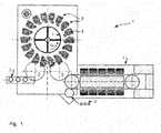
- FIG. 1 is a From Shellstrom 1 shown with a mold filling machine 6 according to the invention.
- this comprises a carousel 4 which can rotate in the direction of rotation 4a.
- one or more mold filling stations 5 are arranged, in which a preform can be formed and filled.
- the mold filling stations 5 each comprise a hollow mold, in which the preform can be clamped, and in which the preform is formed and filled even when the mold is closed.
- each mold filling station has one or more filling valves for filling product into the preform and / or into the container.
- the preforms can be supplied to the carousel 4 from a furnace area 7 via corresponding means 8 for transport, such as rotary stars or conveyors, wherein the transport of the preforms can be carried out, for example, in the neck-handling method.
- further treatment devices such as inspection devices, cleaning devices or the like may be arranged between the furnace area 7 and the carousel 4.
- the filled and molded containers can be removed from the carousel via a corresponding Transport device 9, such as a rotary star, are removed from the carousel 4.
- the molded and filled containers 2 can then be supplied, for example, to further treatment devices, such as a capper or labeling device or printing devices. These can also be understood as part of the mold filling machine 6.
- the mold filling machine according to the invention comprises at least one carousel with corresponding mold filling stations in which the containers or preforms are shaped and filled.
- the filling valve can be separated from the mold filling station.
- the filling valve and the mold filling station are connected to each other via quick-change connections or connection systems. These systems include, for example, plug or click connections.
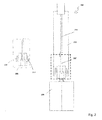
- FIG. 2 shows such an embodiment in which a filling valve 201 is installed in a mold filling station 200.
- This mold filling station comprises, for example, a mold or mold 220 in which a preform can be positioned for molding.
- the mold filling station comprises the essential devices for filling the product and for forming the preform into a container.
- this does not necessarily include, for example, a stretching rod 221 and a forming / filling block 222 in which this stretching rod can be arranged together with the filling valve 201.
- the block 222 together with the mold 220 form the mold filling station.
- the filling valve may comprise or be arranged on a part of the stretch rod 221 '.
- the illustrated connecting elements 211 and 212, in conjunction with corresponding, for example, complementary connecting elements in the mold filling station 200 or the mold / filling block 222 form the quick-change connection.
- the stretch rod 221 is formed in two parts, wherein the part 221 'is detachably connected together with the filling valve 201 with the mold filling station. It can be provided that the arranged in the filling part of the stretch rod 221 is connected via similar releasable connections, in particular via magnetic or electromagnetic connections to the part 221 'of the stretch rod.
- the complementary connection 211, 212 can be formed either mechanically, for example via eccentric lever, clamping lever, centerlock lever and corresponding complementary connecting pieces in the mold filling station or via magnetic or electromagnetic connections.
- the filling valve has or comprises a permanent magnet or has a ferromagnetic material. This can be provided for example in the form of a ring which encloses the filling valve.
- At the Form filling station can then be arranged either also a permanent magnet or more preferably an electromagnet, which can be electromagnetically connected to the permanent magnet of the filling valve.
- the filling valve is separable from the mold filling station
- the filling valve together with, for example, the stretching rod or other components, such as a piston for introducing the liquid to be filled into the filling valve as a form / Railblock are summarized.
- This form / filler block can be quickly connected to the other elements of the mold filling station, so that not only the single filling valve but the entire arrangement of filling valve and form / filling block can be removed from the mold filling station.
- the described embodiments for the quick-change connections may also be provided on the mold / filler block to secure it to the mold filling station.
- the removed filling valve or the removed form / filler block can then be cleaned or other work, such as maintenance, supplied. Likewise, they can be replaced depending on certain production parameters, such as different liquids to be filled (for example, carbonated liquids or still liquids or liquids with different viscosity).
- the cleaning of the filling valve and / or the mold / filling block may alternatively be provided that the filling valve can be isolated from the environment. In this isolated state, a cleaning can then be done using a cleaning device.
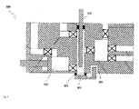
- FIG. 3 shows an embodiment in which a filling valve 301 is arranged at a mold filling station 300.
- This arrangement of the filling valve 301 may, for example, be provided below or in the vicinity of the stretching rod 321.
- a cap 302 is provided, which can be put over the filling valve 301 or moved.
- a bearing 303 may be provided, with which the cap 302 is mounted on the mold filling station.
- the cap 302 may be movably supported around the bearing 303 so that the cap 302 can either be pivoted via the filling valve 301 or can be closed in the direction of the filling valve. Is the Cap has been moved over the filling valve 301, so for example, via a corresponding supply line in the mold filling station cleaning medium in the area was isolated from the cap from the environment and in which the filling valve 301 is introduced to clean the filling valve.
- This supply line can either be provided separately or be carried out, for example, by the piston 322, through which the medium is usually passed for filling into the container via the filling valve 301. At the same time, this area of the mold filling station can be cleaned. This is particularly advantageous if there is a change in the product to be filled into the container.
- the cleaning medium is not passed through the filling valve, but is first introduced via lines leading into the cap 302 in the environment enclosed by the cap.
- the filling valve can then be cleaned with the cleaning medium located in the cap or in the space enclosed by the cap.
- the cleaning medium can then be led out of the cap again or continuously.
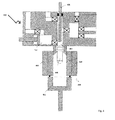
- FIG. 4 shows one to FIG. 3 alternative embodiment in which, as a device for isolating the filling valve 401 from the environment of the mold filling station 400 no separate cap, but the blow mold or mold in which the container is formed from the preform is used.
- the mold 430 which usually comprises two mold halves 433 and 434 and a bottom 432, can be moved up to the filling valve 401 so that a preferably air-tight and / or liquid-tight closing of the filling valve 401 takes place with respect to the surroundings of the mold filling station 400.
- the position of the mold 430 for closing the filling valve 401 may either correspond to the usual position when forming a container from the preform or may be a special cleaning position of the mold 430.
- the supply of cleaning medium can be done for example by separate supply lines, which can be connected to a memory for cleaning medium.
- a memory for cleaning medium This can be arranged on the carousel.
- each mold filling station can be assigned a separate memory.
- These may be filled separately as needed or connected to a supply system which may be located in the mold-filling machine or outside the mold-filling machine.
- a supply system which may be located in the mold-filling machine or outside the mold-filling machine.
- a supply system can be supplied to the storage cleaning medium.
- one or more stores are arranged outside the carousel and are connected via supply lines to the individual mold filling stations.
- a central rotary distributor can be arranged in the mold filling machine, which can forward the cleaning medium from the stores located outside to the individual mold filling stations via a central supply line.
- the mold 430 is not completely empty, but a "container" 431, which may for example have the shape of a preform or be shaped differently, is positioned in the mold 430 to the excess amount to receive cleaning medium. Since the inside of the mold 430 preferably has to be dry when molding a container, the use of such a special container 431 is particularly advantageous when cleaning with a liquid cleaning medium.
- FIG. 5 is one to FIG. 4 illustrated alternative embodiment, in which not the entire shape is closed to the filling valve 401, but in which the mold halves 433 and 434 are moved apart so far that the bottom 432 of the mold 430 are moved in the direction of the filling valve 401 and can enclose this.
- the volume into which the cleaning medium is introduced can be reduced, which is advantageous in particular when using liquid cleaning media, since this way cleaning medium can be saved and nevertheless a corresponding cleaning of the filling valve 401 can take place.
- the bottom 432 is arranged on a movable holder 435. This may be, for example, a movable by means of an actuator axis.
- the supply of cleaning medium can be analogous to that in FIG. 4 described embodiment, in particular with an additional container done.
- FIG. 6 shows a further embodiment. This is an analogous embodiment to that in FIG FIG. 5 shown.
- lines 430 to 630 are provided here in the bottom 432 of the mold 430.
- the emerging cleaning medium can then be used for example for cleaning the remaining parts of the mold, in particular the mold halves 433 and 434.
- This allows for the cleaning of the filling valve 401 either each time or depending on certain cleaning cycles a cleaning of the mold 430, without the mold 430 has to be removed or supplied to an additional cleaning device.
- the lines 661-664 can be closed separately for this purpose.
- FIGS. 3 to 6 illustrated embodiment may also be provided that either the filling valve together with in FIG. 3 described cap or the filling valve is moved out together with the closed this form from the mold filling station and an additional cleaning unit or cleaning device is supplied.
Landscapes
- Engineering & Computer Science (AREA)
- Mechanical Engineering (AREA)
- Manufacturing & Machinery (AREA)
- Filling Of Jars Or Cans And Processes For Cleaning And Sealing Jars (AREA)
- Moulds For Moulding Plastics Or The Like (AREA)
- Blow-Moulding Or Thermoforming Of Plastics Or The Like (AREA)
Abstract
Description
- Die Erfindung betrifft eine Formfüllmaschine nach dem Oberbegriff des Anspruchs 1 und des Anspruchs 7.
- Bekanntermaßen lassen sich Kunststoffbehälter im Streckblasverfahren aus Vorformlingen herstellen.
- Alternativ zu einem Aufblasen der Behälter mit Pressluft beschreibt die
EP 1529620 B1 ein Verfahren zum hydraulischen Umformen von Vorformlingen zu Kunststoffflaschen. Zu diesem Zweck werden die Vorformlinge zuerst erwärmt, in eine Hohlform verbracht und dort in Längsrichtung gereckt. Es wird ferner Mineralwasser oder dergleichen unter Überdruck eingeleitet, um die endgültige Behälterform herzustellen. Das Mineralwasser verbleibt im Behälter, sodass ein nachfolgender separater Abfüllschritt entbehrlich ist. - Die
US 2011/0031659 A1 beschreibt ferner ein Verfahren, bei dem ein erwärmter Vorformling mittels einer Reckstange gereckt und anschließend mittels eines inkompressiblen Fluids, insbesondere Wasser, hydraulisch zu einem Behälter geweitet wird. Danach wird das Fluid durch Pressluft verdrängt und läuft aus dem Behälter ab. - Eine Formfüllmaschine umfasst definitionsgemäß wenigstens eine Behandlungsstation zum expandierenden Umformen von Kunststoffvorformlingen zu Kunststoffbehältern in einer Hohlform und zum Einfüllen eines im Wesentlichen flüssigen Produkts oder wenigstens einer flüssigen oder festen Komponente des Produkts in die Kunststoffbehälter.
- Flüssigkeiten, auch solche mit darin gelöstem Kohlendioxid oder dergleichen, sind definitionsgemäß hinsichtlich ihrer Funktion beim Ausformen und Füllen der Behälter inkompressible Fluide im Gegensatz zu Gasen, die funktional als kompressible Fluide definiert sind.
- Aufgabe der vorliegenden Erfindung ist es, bekannte Vorrichtungen und Verfahren zum Ausformen und Füllen von Kunststoffbehältern in vorteilhafter Weise weiterzubilden.
- Diese Aufgabe wird mit einer Formfüllmaschine nach Anspruch 1 gelöst. Vorteilhafte Ausführungsformen der Erfindung sind in den Unteransprüchen definiert.
- Die erfindungsgemäße Formfüllmaschine ist dadurch gekennzeichnet, dass das Füllventil schnellwechselbar mit der Formfüllstation verbunden ist. Auf diese Weise kann das Füllventil mit relativ geringem Aufwand beispielsweise zu Reinigungszwecken oder zum Austausch bei Verwendung anderer Produkte oder zum Realisieren anderer Anforderungen ausgetauscht werden.
- In einer weiteren Ausführungsform kann vorgesehen sein, dass das Füllventil kraft- und formschlüssig mit der Formfüllstation verbunden ist. Eine Fehlstellung des Füllventils und ein damit einhergehendes fehlerhaftes Abfüllen von Produkt in den Behälter kann so vermieden werden.
- In einer weiteren Ausführungsform können das Füllventil und die Formfüllstation über wenigstens eines von Exzenterhebeln, Spannhebeln, Centerlockhebeln lösbar miteinander verbunden sein. Diese Verbindungen sind lösbar, bieten jedoch eine genaue kraft- und formschlüssige Verbindungen der Elemente untereinander.
- Es kann zusätzlich oder alternativ vorgesehen sein, dass das Füllventil einen Dauermagneten oder ein ferromagnetisches Material umfasst und die Formfüllstation einen Elektromagneten umfasst, wobei die lösbare Verbindung durch die Magnete gebildet wird. Diese Ausführungsform erlaubt durch an- und ausschalten des Elektromagneten ein leichteres und schnelleres Austauschen des Füllventils.
- Es kann weiterhin vorgesehen sein, dass das Füllventil in einem Form/Füllblock angeordnet ist, der einen Teil der Reckstange zum Verstrecken des Vorformlings umfasst und wobei der Form/Füllblock schnellwechselbar mit der Formfüllstation verbunden ist. So kann der gesamte Form/Füllblock ausgetauscht und beispielsweise an bestimmte Bedingungen, wie Einleiten eines anderen Produkts, angepasst werden. Außerdem kann so bei einem Defekt der Form/Füllblock insgesamt ausgetauscht werden, um Stillstandszeiten zu minimieren, die entstehen würden, wenn eine Fehlersuche an dem eingebauten Form/Füllblock durchgeführt werden würde.
- In einer Weiterbildung diese Ausführungsform kann ein Kolben zum Einleiten von Medium durch das Füllventil im Form/Füllblock angeordnet sein.
- Eine alternative Formfüllmaschine zur Lösung der obigen Aufgabe ist dadurch gekennzeichnet, dass das Füllventil von der Umgebung isoliert werden kann und in Isolation gereinigt werden kann. Gemäß dieser erfindungsgemäßen Formfüllmaschine ist es nicht mehr notwendig das Füllventil zum Zweck der Reinigung auszubauen, so dass beispielsweise zwischen zwei unterschiedlichen Füllchargen eine Reinigung des Füllventils erfolgen kann. Durch das Isolieren des Füllventils kann das Umherspritzen von Reinigungsmedium oder von in dem Füllventil verbliebenem Produkt vermieden werden, sodass die übrige Formfüllmaschine dadurch nicht beeinträchtigt wird.
- In einer Ausführungsform ist die erfindungsgemäße Formfüllmaschine dadurch gekennzeichnet, dass eine Kappe über dem Ausgang des Füllventils positioniert werden kann, die das Füllventil in einem Bereich von der Umgebung abschließen kann, wobei in das Füllventil und in den Bereich ein Reinigungsmedium zum Reinigen des Füllventils eingebracht werden kann. Der Bereich, in dem das Füllventil von der Umgebung isoliert wird, kann so relativ klein gewählt werden, was auch die Menge an zu benutzenden Reinigungsmedium reduziert.
- In einer Weiterbildung dieser Ausführungsform kann vorgesehen sein, dass das Reinigungsmedium durch eine mit dem Füllventil verbundene Leitung geführt wird, aus dem Füllventil in den Bereich geleitet und durch eine Absaugung wieder abgesaugt wird. Es kann so ein kontinuierlicher Fluss an Reinigungsmedium sichergestellt werden, sodass eventuelle Verunreinigungen des Füllventils nicht in der Umgebung und insbesondere weder in der Kappe noch im Füllventil verbleiben.
- In einer alternativen Weiterbildung der Ausführungsform ist vorgesehen, dass ein Reinigungsmedium durch die Kappe in den Bereich und das Füllventil geführt und aus dem Füllventil und dem Bereich durch eine Absaugung abgesaugt wird. So können zusätzliche Leitungen, die in der Formfüllstation ausgelegt werden müssen, um das Füllventil mit Reinigungsmedium zu versorgen, eingespart werden, was zu einer kleiner bauenden Formfüllstation führen kann. Da die Kappe und die damit verbundenen Leitungen als separate Baueinheit ausgebildet sein kann, können diese nur bei Bedarf dem entsprechenden Füllventil zugeführt werden.
- Weiterhin kann vorgesehen sein, dass das Füllventil in einer Reinigungsstellung einfahrbar ist, wobei in der Reinigungsstellung eine Reinigungseinrichtung angeordnet ist, die das Füllventil reinigen kann. Diese Reinigungsstellung kann beispielsweise bei rotierenden Formfüllmaschinen zwischen den Zuförderern und den Abförderern für die Vorformling bzw. Behälter angeordnet sein, sodass bei notwendiger Reinigungen die entsprechende Formfüllstation mit dem Füllventil in diese Position gefahren und von der Reinigungseinrichtung gereinigt wird.
- Ferner kann ein flüssiges oder gasförmiges Reinigungsmedium verwendet werden. Ein flüssiges Reinigungsmedium kann eine sehr hohe Reinigungswirkung entfalten wohingegen ein gasförmiges Reinigungsmedium nahezu ohne Rückstände aus dem Füllventil abgesaugt werden kann, sodass der weitere Betrieb störungsfrei verlaufen kann und nicht eventuell durch das Füllventil abgefülltes Produkt mit dem Reinigungsmedium verunreinigt wird.
-
- Figur 1:
- schematische Darstellung einer erfindungsgemäßen Formfüllmaschine
- Figur 2:
- schematische Darstellung einer Ausführungsform mit Schnellwechselsystem
- Figur 3:
- schematische Darstellung einer Ausführungsform mit Kappe
- Figur 4:
- schematische Darstellung einer Ausführungsform mit Form als Kappe
- Figur 5:
- schematische Darstellung einer Ausführungsform mit Formboden als Kappe
- Figur 6:
- schematische Darstellung einer Ausführungsform mit zusätzlicher Spülung für die Formen
- in
Figur 1 ist eine Fromfüllanlage 1 mit einer erfindungsgemäßen Formfüllmaschine 6 dargestellt. Diese umfasst in der hier dargestellten Ausführungsform ein Karussell 4, das sich in der Drehrichtung 4a drehen kann. An dem Karussell 4 sind ein oder mehrere Formfüllstationen 5 angeordnet, in denen ein Vorformling ausgeformt und befüllt werden kann. Dazu umfassen die Formfüllstationen 5 jeweils eine Hohlform, in der der Vorformling eingespannt werden kann, und in der der Vorformling ausgeformt und auch bei geschlossener Hohlform befüllt wird. Zu diesem Zweck ist vorgesehen, dass jede Formfüllstation über ein oder mehrere Füllventile zum Abfüllen von Produkt in den Vorformling und/oder in den Behälter verfügt. - Die Vorformlinge können aus einem Ofenbereich 7 über entsprechende Mittel zum Transport 8, wie beispielsweise Drehsterne oder Förderer, dem Karussell 4 zugeführt werden, wobei der Transport der Vorformlinge beispielsweise im Neck-Handling-Verfahren erfolgen kann. Zwischen dem Ofenbereich 7 und dem Karussell 4 können beispielsweise weitere Behandlungseinrichtungen, wie Inspektionseinrichtungen, Reinigungseinrichtungen oder Ähnliches angeordnet sein.
- Die befüllten und ausgeformten Behälter können aus dem Karussell über eine entsprechende Transporteinrichtung 9, wie beispielsweise einen Drehstern, aus dem Karussell 4 abtransportiert werden. Die ausgeformten und befüllten Behälter 2 können dann beispielsweise weiteren Behandlungseinrichtungen, wie einem Verschließer oder Etikettiereinrichtungen oder Druckeinrichtungen zugeführt werden. Diese können ebenfalls als Bestandteil der Formfüllmaschine 6 verstanden werden. Grundsätzlich umfasst die erfindungsgemäße Formfüllmaschine jedoch wenigstens ein Karussell mit entsprechenden Formfüllstationen, in denen die Behälter bzw. Vorformlinge ausgeformt und befüllt werden.
- Gemäß der Erfindung ist vorgesehen dass das Füllventil von der Formfüllstation abtrennbar ist. Zu diesem Zweck ist vorgesehen, dass das Füllventil und die Formfüllstation miteinander über schnellwechselbare Verbindungen oder Verbindungssysteme verbunden sind. Zu diesen Systemen zählen beispielsweise Steck- oder Klickverbindungen.
-
Figur 2 zeigt eine solche Ausführungsform, bei der ein Füllventil 201 in eine Formfüllstation 200 eingebaut ist. Diese Formfüllstation umfasst beispielsweise eine Hohlform oder Form 220, in der ein Vorformling zum Ausformen positioniert werden kann. Weiterhin umfasst die Formfüllstation die wesentlichen Vorrichtungen zum Einfüllen des Produkts und zum Ausformen des Vorformlings zu einem Behälter. Dazu zählt beispielsweise aber nicht notwendigerweise eine Reckstange 221 und ein Form/Füllblock 222 in dem diese Reckstange zusammen mit dem Füllventil 201 angeordnet werden kann. Der Block 222 bildet gemeinsam mit der Form 220 die Formfüllstation. - Das Füllventil kann einen Teil der Reckstange 221' umfassen bzw. an diesem angeordnet sein. Die dargestellten Verbindungselemente 211 und 212 bilden in Verbindung mit entsprechenden beispielsweise komplementären Verbindungselementen in der Formfüllstation 200 bzw. dem Form/Füllblock 222 die schnellwechselbare Verbindung.
- Vorteilhaft ist, wenn die Reckstange 221 zweiteilig ausgebildet ist, wobei der Teil 221' zusammen mit dem Füllventil 201 lösbar mit der Formfüllstation verbunden ist. Dabei kann vorgesehen sein, dass der in der Füllstation angeordnete Teil der Reckstange 221 über ähnliche lösbare Verbindungen, insbesondere über magnetische oder elektromagnetische Verbindungen mit dem Teil 221' der Reckstange verbindbar ist.
- Die komplementäre Verbindung 211, 212 kann entweder mechanisch beispielsweise über Exzenterhebel, Spannhebel, Centerlockhebel und entsprechende komplementäre Verbindungsstücke in der Formfüllstation gebildet werden oder über magnetische bzw. elektromagnetische Verbindungen. Dazu kann vorgesehen sein, dass das Füllventil über einen Dauermagneten verfügt bzw. diesen umfasst oder ein ferromagnetisches Material aufweist. Dieses kann beispielsweise in Form eines Ringes, der das Füllventil umschließt, vorgesehen sein. An der Formfüllstation kann dann entweder ebenfalls ein Dauermagnet oder besonders bevorzugt ein Elektromagnet angeordnet sein, der mit dem Dauermagnet des Füllventils elektromagnetisch verbunden werden kann. Über geeignete Wahl der Feldstärken, insbesondere bei Verwendung eines Elektromagneten, kann so ein sicherer Halt des Füllventils gewährleistet werden und gleichzeitig eine einfache Lösbarkeit des Füllventils durch Abschalten des Elektromagneten erreicht werden. So können unerwünschte Stillstandszeiten beim Austausch der Füllventile vermieden bzw. verringert werden.
- Während in den bisherigen Ausführungsformen beschrieben wurde, dass das Füllventil von der Formfüllstation trennbar ist, kann auch vorgesehen sein, dass das Füllventil zusammen mit beispielsweise der Reckstange oder anderen Komponenten, wie beispielsweise ein Kolben zum Einleiten der abzufüllenden Flüssigkeit in das Füllventil als Form/Füllblock zusammengefasst sind. Dieser Form/Füllblock kann schnellwechselbar mit den übrigen Elementen der Formfüllstation verbunden sein, sodass nicht nur das einzelne Füllventil sondern die gesamte Anordnung aus Füllventil und Form/Füllblock von der Formfüllstation abgenommen werden kann. Die beschriebenen Ausführungsformen für die schnellwechselbaren Verbindungen können auch an dem Form/Füllblock vorgesehen sein, um diesen an der Formfüllstation zu befestigen.
- Das abgenommene Füllventil bzw. der abgenommene Form/Füllblock kann dann gereinigt oder anderen Arbeiten, wie beispielsweise Wartungsarbeiten, zugeführt werden. Ebenso können sie abhängig von bestimmten Produktionsparametern, wie beispielsweise unterschiedlichen abzufüllenden Flüssigkeiten (beispielsweise kohlensäurehaltige Flüssigkeiten oder stille Flüssigkeiten oder Flüssigkeiten mit unterschiedlicher Viskosität), ausgetauscht werden.
- Insbesondere mit Hinblick auf die Reinigung des Füllventils und/oder des Form/Füllblocks kann alternativ vorgesehen sein, dass das Füllventil von der Umgebung isoliert werden kann. In diesem isolierten Zustand kann dann eine Reinigung mithilfe einer Reinigungsvorrichtung erfolgen.
- Dazu zeigt
Figur 3 eine Ausführungsform, bei der an einer Formfüllstation 300 ein Füllventil 301 angeordnet ist. Diese Anordnung des Füllventils 301 kann beispielsweise unterhalb oder in der Nähe der Reckstange 321 vorgesehen sein. - Um das Füllventil 301 in dieser Ausführungsform zumindest von der Umgebung außerhalb der Formfüllstation 300 zu isolieren, ist eine Kappe 302 vorgesehen, die über das Füllventil 301 gestülpt bzw. bewegt werden kann. Dazu kann beispielsweise eine Lagerung 303 vorgesehen sein, mit der die Kappe 302 an der Formfüllstation gelagert ist. Die Kappe 302 kann um die Lagerung 303 beweglich gelagert sein so dass die Kappe 302 entweder über das Füllventil 301 geschwenkt werden kann oder in Richtung auf das Füllventil zugefahren werden kann. Ist die Kappe über das Füllventil 301 gefahren worden, so kann beispielsweise über eine entsprechend Zuleitung in der Formfüllstation Reinigungsmedium in den Bereich der von der Kappe von der Umgebung isoliert wurde und in dem sich das Füllventil 301 befindet, eingeleitet werden, um das Füllventil zu reinigen. Diese Zuleitung kann entweder separat vorgesehen sein oder beispielsweise durch den Kolben 322 erfolgen durch den üblicherweise das Medium zum Abfüllen in den Behälter über das Füllventil 301 geführt wird. So kann gleichzeitig eine Reinigung dieses Bereichs der Formfüllstation erfolgen. Dies ist insbesondere dann von Vorteil wenn eine Änderung des in die Behälter abzufüllenden Produkts erfolgt.
- Alternativ dazu kann auch vorgesehen sein, dass das Reinigungsmedium nicht durch das Füllventil geleitet wird, sondern zunächst über Leitungen, die in die Kappe 302 führen, in die von der Kappe eingeschlossene Umgebung eingeleitet wird. Das Füllventil kann dann mit der in der Kappe bzw. in dem von der Kappe eingeschlossenen Raum befindlichen Reinigungsmedium gereinigt werden. Das Reinigungsmedium kann anschließend oder kontinuierlich wieder aus der Kappe heraus geleitet werden.
-
Figur 4 zeigt eine zurFigur 3 alternative Ausführungsform, bei der als Vorrichtung zum Isolieren des Füllventils 401 von der Umgebung der Formfüllstation 400 keine separate Kappe, sondern die Blasformen bzw. Form, in der der Behälter aus dem Vorformling ausgeformt wird, verwendet wird. Dazu kann die Form 430, die üblicherweise zwei Formhälften 433 und 434 sowie einen Boden 432 umfasst, an das Füllventil 401 herangefahren werden, sodass ein vorzugsweise luft- und/oder flüssigkeitsdichtes Verschließen des Füllventils 401 gegenüber der Umgebung der Formfüllstation 400 erfolgt. Dabei kann die Position der Form 430 zum Verschließen des Füllventils 401 entweder der üblichen Position beim Ausformen eines Behälters aus dem Vorformling entsprechen oder eine besondere Reinigungsstellung der Form 430 sein. - Die Zuleitung von Reinigungsmedium kann beispielsweise durch separate Zuleitungen erfolgen, die mit einem Speicher für Reinigungsmedium verbunden sein können. Dieser kann auf dem Karussell angeordnet sein. Insbesondere kann jeder Formfüllstation ein separater Speicher zugeordnet sein. Diese können je nach Notwendigkeit separat gefüllt werden oder mit einem Versorgungssystem, das in der Formfüllmaschine oder außerhalb der Formfüllmaschine angeordnet sein kann, verbunden sein. Über dieses Versorgungssystem kann den Speichern Reinigungsmedium zugeleitet werden. Es kann auch vorgesehen sein, dass ein oder mehrere Speicher außerhalb des Karussells angeordnet sind und über Zuleitungen mit den einzelnen Formfüllstationen verbunden sind. Insbesondere kann hierzu ein zentraler Drehverteiler in der Formfüllmaschine angeordnet sein, der über eine zentrale Zuleitung das Reinigungsmedium aus den außerhalb angeordneten Speichern den einzelnen Formfüllstationen zuleiten kann.
- Dabei ist es besonders vorteilhaft, wenn während der Reinigung die Form 430 nicht vollständig leer ist, sondern ein "Behälter" 431, der beispielsweise die Form eines Vorformlings haben kann oder anders geformt sein kann, in der Form 430 positioniert ist, um die überschüssige Menge an Reinigungsmedium aufzunehmen. Da die Innenseite der Form 430 beim Ausformen eines Behälters vorzugsweise trocken sein muss, ist die Verwendung eines solchen speziellen Behälters 431 insbesondere bei Reinigung mit einem flüssigen Reinigungsmedium vorteilhaft.
- In
Figur 5 ist eine zurFigur 4 alternative Ausführungsform dargestellt, bei der nicht die gesamte Form um das Füllventil 401 geschlossen wird, sondern bei der die Formhälften 433 und 434 so weit auseinandergefahren werden, dass der Boden 432 der Form 430 in Richtung des Füllventils 401 verfahren werden und dieses umschließen kann. So kann das Volumen, in den das Reinigungsmedium eingeleitet wird verringert werden, was insbesondere bei Verwendung von flüssigen Reinigungsmedien vorteilhaft ist, da so Reinigungsmedium eingespart werden kann und trotzdem eine entsprechende Reinigung des Füllventils 401 erfolgen kann. Um die Bewegung des Bodens 432 der Form 430 zu ermöglichen, kann vorgesehen sein, dass der Boden 432 auf einer bewegbaren Halterung 435 angeordnet ist. Dabei kann es sich beispielsweise um eine mittels eines Stellantriebs bewegbare Achse handeln. - Die Zuführung von Reinigungsmedium kann analog zu der in
Figur 4 beschriebenen Ausführungsform, insbesondere auch mit einem zusätzlichen Behälter, erfolgen. -
Figur 6 zeigt eine weitere Ausführungsform. Hierbei handelt es sich um eine analoge Ausführungsform zu der inFigur 5 dargestellten. Zusätzlich zu der Möglichkeit, das Füllventil 401 mit Reinigungsmedium zu reinigen, sind hier im Boden 432 der Form 430 Leitungen 661 bis 664 vorgesehen. Durch diese kann das Reinigungsmedium, das durch das Füllventil 401 geleitet wird, aus dem Boden 433 ausgeleitet werden. Das austretende Reinigungsmedium kann dann beispielsweise zur Reinigung der übrigen Teile der Form, insbesondere der Formhälften 433 und 434 genutzt werden. Dies erlaubt bei der Reinigung des Füllventil 401 entweder jedes Mal oder in Abhängigkeit bestimmter Reinigungszyklen eine Reinigung der Form 430, ohne dass die Form 430 dafür ausgebaut oder einer zusätzlichen Reinigungseinrichtung zugeführt werden muss. Die Leitungen 661-664 können dafür separat verschließbar sein. - Alternativ zu den in
Figur 3 bis 6 dargestellten Ausführungsform kann auch vorgesehen sein, dass entweder das Füllventil zusammen mit der inFigur 3 beschriebenen Kappe oder das Füllventil zusammen mit der um dieses geschlossenen Form aus der Formfüllstation herausgefahren wird und einer zusätzlichen Reinigungseinheit bzw. Reinigungseinrichtung zugeführt wird.
Claims (12)
- Formfüllmaschine (6) mit einer oder mehrerer Formfüllstationen (5) zum Formen von Vorformlingen zu Behältern und Füllen der Behälter in einer Form, wobei ein Füllventil (201) in der Formfüllstation angeordnet ist, über das Produkt in den Behälter gefüllt werden kann, dadurch gekennzeichnet, dass das Füllventil (201) schnellwechselbar mit der Formfüllstation (5) verbunden ist.
- Formfüllmaschine nach Anspruch 1, dadurch gekennzeichnet, dass das Füllventil (201) kraft- und formschlüssig mit der Formfüllstation (5) verbunden ist.
- Formfüllmaschine nach Anspruch 1 oder 2, dadurch gekennzeichnet, dass das Füllventil (201) und die Formfüllstation über wenigstens eines von Exzenterhebeln, Spannhebeln, Centerlockhebeln lösbar miteinander verbunden sind.
- Formfüllmaschine nach einem der Ansprüche 1 bis 3, dadurch gekennzeichnet, dass das Füllventil (201) einen Dauermagneten oder ein ferromagnetisches Material umfasst und die Formfüllstation einen Elektromagneten umfasst, wobei die lösbare Verbindung durch die Magnete gebildet wird.
- Formfüllmaschine nach einem der Ansprüche 1 bis 4, dadurch gekennzeichnet, dass das Füllventil in einem Form/Füllblock (222) angeordnet ist, der einen Teil einer Reckstange (221) zum Verstrecken des Vorformlings umfasst und wobei der Form/Füllblock (222) schnellwechselbar mit der Formfüllstation verbunden ist.
- Formfüllstation nach Anspruch 5, dadurch gekennzeichnet, dass in dem Form/Füllblock ein Kolben (322) zum Einleiten von Medium durch das Füllventil angeordnet ist.
- Formfüllmaschine (6) mit einer oder mehrerer Formfüllstationen (5) zum Formen von Vorformlingen zu Behältern und Füllen der Behälter in einer Form, wobei ein Füllventil (301) in der Formfüllstation (5) angeordnet ist, über das Produkt in den Behälter gefüllt werden kann, dadurch gekennzeichnet, dass das Füllventil (301) von der Umgebung isoliert werden kann und in Isolation gereinigt werden kann.
- Formfüllmaschine nach Anspruch 7, dadurch gekennzeichnet, dass eine Kappe (302) über dem Ausgang des Füllventils (301) positioniert werden kann, die das Füllventil (301) in einem Bereich von der Umgebung abschließen kann, wobei in das Füllventil und in den Bereich ein Reinigungsmedium zum Reinigen des Füllventils eingebracht werden kann.
- Formfüllmaschine nach Anspruch 8, dadurch gekennzeichnet, dass das Reinigungsmedium durch eine mit dem Füllventil verbundene Leitung geführt, aus dem Füllventil in den Bereich geleitet und durch eine Absaugung abgesaugt werden kann.
- Formfüllmaschine nach Anspruch 8, dadurch gekennzeichnet, dass ein Reinigungsmedium durch die Kappe (302) in den Bereich und das Füllventil (301) geführt und aus dem Füllventil und dem Bereich durch eine Absaugung abgesaugt werden kann.
- Formfüllmaschine nach Anspruch 7, dadurch gekennzeichnet, dass das Füllventil in eine Reinigungsstellung verfahrbar ist, wobei in der Reinigungsstellung eine Reinigungseinrichtung angeordnet ist, die das Füllventil reinigen kann.
- Formfüllmaschine nach einem der Ansprüche 7 bis 11, dadurch gekennzeichnet, dass ein flüssiges oder gasförmiges Reinigungsmedium verwendet wird.
Priority Applications (1)
| Application Number | Priority Date | Filing Date | Title |
|---|---|---|---|
| EP14181654.6A EP2987732B1 (de) | 2014-08-20 | 2014-08-20 | Formfüllmaschine |
Applications Claiming Priority (1)
| Application Number | Priority Date | Filing Date | Title |
|---|---|---|---|
| EP14181654.6A EP2987732B1 (de) | 2014-08-20 | 2014-08-20 | Formfüllmaschine |
Publications (2)
| Publication Number | Publication Date |
|---|---|
| EP2987732A1 true EP2987732A1 (de) | 2016-02-24 |
| EP2987732B1 EP2987732B1 (de) | 2018-05-02 |
Family
ID=51389984
Family Applications (1)
| Application Number | Title | Priority Date | Filing Date |
|---|---|---|---|
| EP14181654.6A Active EP2987732B1 (de) | 2014-08-20 | 2014-08-20 | Formfüllmaschine |
Country Status (1)
| Country | Link |
|---|---|
| EP (1) | EP2987732B1 (de) |
Cited By (1)
| Publication number | Priority date | Publication date | Assignee | Title |
|---|---|---|---|---|
| DE102018110036A1 (de) * | 2018-04-26 | 2019-10-31 | Krones Ag | Sterilisierbare Blasluftwege und Reckstange einer Blasmaschine |
Citations (13)
| Publication number | Priority date | Publication date | Assignee | Title |
|---|---|---|---|---|
| US20050098230A1 (en) * | 2003-11-10 | 2005-05-12 | Demetrios Stavrakis | Filling valve apparatus having a quick connect/release mechanism |
| WO2006108380A2 (de) * | 2005-04-12 | 2006-10-19 | Sig Technology Ltd. | Verfahren und vorrichtung zur positionierung eines bauelements |
| EP1529620B1 (de) | 2003-11-06 | 2009-02-25 | Nestlé Waters Management & Technology | Herstellungsverfahren von Behältern aus Polyesterharz |
| EP2255949A1 (de) * | 2009-05-29 | 2010-12-01 | Krones AG | Blasmaschine mit CIP-Reinigungssystem zur Herstellung von Kunststoff-Flaschen, und entsprechendes Verfahren |
| US20110031659A1 (en) | 2005-03-15 | 2011-02-10 | Graeme Warner | Stretch Blow Moulding Method and Apparatus |
| EP2283991A2 (de) * | 2009-08-11 | 2011-02-16 | Krones AG | Blasformmaschine mit Reinigungssystem |
| EP2520539A1 (de) * | 2011-05-04 | 2012-11-07 | Krones AG | Behälterbehandlungsmaschine |
| WO2012156013A1 (de) * | 2011-05-19 | 2012-11-22 | Khs Gmbh | Verfahren und vorrichtung zum reinigen und/oder desinfizieren einer vorrichtung zur herstellung von mit einem flüssigen füllgut gefüllten behältern |
| DE102011110840A1 (de) * | 2011-08-23 | 2013-02-28 | Khs Gmbh | Füllmaschine sowie Verfahren zum Steuern einer Füllmaschine |
| WO2013145511A1 (ja) * | 2012-03-30 | 2013-10-03 | 株式会社吉野工業所 | ブロー成形装置 |
| WO2013147065A1 (ja) * | 2012-03-30 | 2013-10-03 | 株式会社吉野工業所 | 内容液入り容器の製造方法、容器内部の陽圧化方法及び充填容器、並びに、ブロー成形方法及びブロー成形装置 |
| EP2669070A1 (de) * | 2012-06-02 | 2013-12-04 | Krones AG | Hohlkörperherstellungsmaschine |
| WO2014103188A1 (ja) * | 2012-12-28 | 2014-07-03 | 株式会社吉野工業所 | ブロー成形装置 |
Family Cites Families (3)
| Publication number | Priority date | Publication date | Assignee | Title |
|---|---|---|---|---|
| DE102013106694A1 (de) * | 2013-06-26 | 2015-01-15 | Krones Ag | Verfahren und Vorrichtung zum Umformen von Kunststoffvorformlingen zu Kunststoffbehältnissen |
| JP6530416B2 (ja) * | 2013-10-21 | 2019-06-12 | ディスクマ アクチェンゲゼルシャフト | 容器の内部の液体を安定化させる安定化領域を備えた、容器を形成かつ充填する装置 |
| FR3020008B1 (fr) * | 2014-04-16 | 2016-05-20 | Sidel Participations | Unite de moulage comportant des moyens d'actionnement d'un fond de moule portes par un support fixe |
-
2014
- 2014-08-20 EP EP14181654.6A patent/EP2987732B1/de active Active
Patent Citations (13)
| Publication number | Priority date | Publication date | Assignee | Title |
|---|---|---|---|---|
| EP1529620B1 (de) | 2003-11-06 | 2009-02-25 | Nestlé Waters Management & Technology | Herstellungsverfahren von Behältern aus Polyesterharz |
| US20050098230A1 (en) * | 2003-11-10 | 2005-05-12 | Demetrios Stavrakis | Filling valve apparatus having a quick connect/release mechanism |
| US20110031659A1 (en) | 2005-03-15 | 2011-02-10 | Graeme Warner | Stretch Blow Moulding Method and Apparatus |
| WO2006108380A2 (de) * | 2005-04-12 | 2006-10-19 | Sig Technology Ltd. | Verfahren und vorrichtung zur positionierung eines bauelements |
| EP2255949A1 (de) * | 2009-05-29 | 2010-12-01 | Krones AG | Blasmaschine mit CIP-Reinigungssystem zur Herstellung von Kunststoff-Flaschen, und entsprechendes Verfahren |
| EP2283991A2 (de) * | 2009-08-11 | 2011-02-16 | Krones AG | Blasformmaschine mit Reinigungssystem |
| EP2520539A1 (de) * | 2011-05-04 | 2012-11-07 | Krones AG | Behälterbehandlungsmaschine |
| WO2012156013A1 (de) * | 2011-05-19 | 2012-11-22 | Khs Gmbh | Verfahren und vorrichtung zum reinigen und/oder desinfizieren einer vorrichtung zur herstellung von mit einem flüssigen füllgut gefüllten behältern |
| DE102011110840A1 (de) * | 2011-08-23 | 2013-02-28 | Khs Gmbh | Füllmaschine sowie Verfahren zum Steuern einer Füllmaschine |
| WO2013145511A1 (ja) * | 2012-03-30 | 2013-10-03 | 株式会社吉野工業所 | ブロー成形装置 |
| WO2013147065A1 (ja) * | 2012-03-30 | 2013-10-03 | 株式会社吉野工業所 | 内容液入り容器の製造方法、容器内部の陽圧化方法及び充填容器、並びに、ブロー成形方法及びブロー成形装置 |
| EP2669070A1 (de) * | 2012-06-02 | 2013-12-04 | Krones AG | Hohlkörperherstellungsmaschine |
| WO2014103188A1 (ja) * | 2012-12-28 | 2014-07-03 | 株式会社吉野工業所 | ブロー成形装置 |
Cited By (2)
| Publication number | Priority date | Publication date | Assignee | Title |
|---|---|---|---|---|
| DE102018110036A1 (de) * | 2018-04-26 | 2019-10-31 | Krones Ag | Sterilisierbare Blasluftwege und Reckstange einer Blasmaschine |
| US11685099B2 (en) | 2018-04-26 | 2023-06-27 | Krones Ag | Sterilizable blowing air paths and stretching rod of a blow moulding machine |
Also Published As
| Publication number | Publication date |
|---|---|
| EP2987732B1 (de) | 2018-05-02 |
Similar Documents
| Publication | Publication Date | Title |
|---|---|---|
| DE69905212T2 (de) | Automatische Maschine zum Herstellen, Überprüfen, Füllen und Verschliessen von Flaschen aus Kunststoffmaterial | |
| EP2531440B1 (de) | Vorrichtung und verfahren zum automatisierten formen und abfüllen von behältern | |
| DE102011102090B4 (de) | Verfahren zum Reinigen und/oder Desinfizieren einer Vorrichtung zur Herstellung von mit einem flüssigen Füllgut gefüllten Behältern sowie Vorrichtung | |
| EP2958805B1 (de) | Verfahren und vorrichtung zur herstellung und füllen von behältern | |
| CH342368A (de) | Verfahren und Maschine zur Herstellung von Flaschen aus plastischem Material | |
| EP2848387B1 (de) | Blasformmaschine mit pneumatisch betätigtem blasluftventil und verfahren zum betreiben einer solchen blasformmaschine | |
| DE102013105221A1 (de) | Behälterbehandlungsmaschine sowie Verfahren zum Betrieb einer Behälterbehandlungsmaschine | |
| EP3640005B1 (de) | Formfüllen mit anschliessender verschliessung unter innendruck | |
| WO2019043122A2 (de) | Vorrichtung mit schnellwechsel tellerträger und verschiebbarer führungskurve | |
| EP3227084B1 (de) | Reckstange für den form- und füllkopf einer maschine zum formen und füllen von behältern aus vorformlingen | |
| DE102011102056A1 (de) | Verfahren sowie Vorrichtung zum Herstellen von gefüllten Behältern aus Vorformlingen | |
| EP2987605B1 (de) | Transportsystem und Verfahren zum Transport von Kunststoffbehältern | |
| EP3186063B1 (de) | System zur weiterbehandlung von mittels spritzgiessen hergestellter vorformlinge | |
| DE102013019892B4 (de) | Hohlkörperherstellungsmaschine und Verfahren zum Umformen eines Vorformlings | |
| EP2987732B1 (de) | Formfüllmaschine | |
| EP2913174B1 (de) | Blasformmaschine mit Zentrierung des Blasformbodens | |
| DE69906589T2 (de) | Verfahren zum zurückdrängen von produkten in einer abfüllmaschine und abfüllmaschine zur durchführung des verfahrens | |
| EP2539133A1 (de) | Vorrichtung und verfahren zum herstellen etikettierter kunststoffbehälter | |
| EP2987622B1 (de) | Formfüllmaschine und Verfahren zum Ausformen und Füllen von Behältern | |
| EP2559544B1 (de) | Vorrichtung und Verfahren zum Umformen von Kunststoffvorformlingen zu Kunststoffbehältnissen mit Druckkissen | |
| DE69906590T2 (de) | Abfüllmaschine mit abfüllköpfen mit jeweils nach unten verstztem flüssigkeitsventil | |
| EP2987612A1 (de) | Formfüllmaschine und Formfüllverfahren für einen Kunststoffbehälter | |
| EP4302965A1 (de) | Vorrichtung und verfahren zum behandeln von behältnissen mit sensoreinrichtung zur füllstandsmessung | |
| EP2987609A1 (de) | Formfüllmaschine mit Reinigung und Verfahren | |
| EP2987613B1 (de) | Formfüllmaschine |
Legal Events
| Date | Code | Title | Description |
|---|---|---|---|
| PUAI | Public reference made under article 153(3) epc to a published international application that has entered the european phase |
Free format text: ORIGINAL CODE: 0009012 |
|
| 17P | Request for examination filed |
Effective date: 20151124 |
|
| AK | Designated contracting states |
Kind code of ref document: A1 Designated state(s): AL AT BE BG CH CY CZ DE DK EE ES FI FR GB GR HR HU IE IS IT LI LT LU LV MC MK MT NL NO PL PT RO RS SE SI SK SM TR |
|
| AX | Request for extension of the european patent |
Extension state: BA ME |
|
| 17Q | First examination report despatched |
Effective date: 20161207 |
|
| RIC1 | Information provided on ipc code assigned before grant |
Ipc: B65B 3/02 20060101AFI20171012BHEP Ipc: B29C 49/12 20060101ALI20171012BHEP Ipc: B29C 49/46 20060101ALN20171012BHEP Ipc: B08B 9/027 20060101ALI20171012BHEP |
|
| GRAP | Despatch of communication of intention to grant a patent |
Free format text: ORIGINAL CODE: EPIDOSNIGR1 |
|
| RIC1 | Information provided on ipc code assigned before grant |
Ipc: B08B 9/027 20060101ALI20171106BHEP Ipc: B65B 3/02 20060101AFI20171106BHEP Ipc: B29C 49/46 20060101ALN20171106BHEP Ipc: B29C 49/12 20060101ALI20171106BHEP |
|
| INTG | Intention to grant announced |
Effective date: 20171121 |
|
| GRAS | Grant fee paid |
Free format text: ORIGINAL CODE: EPIDOSNIGR3 |
|
| GRAA | (expected) grant |
Free format text: ORIGINAL CODE: 0009210 |
|
| AK | Designated contracting states |
Kind code of ref document: B1 Designated state(s): AL AT BE BG CH CY CZ DE DK EE ES FI FR GB GR HR HU IE IS IT LI LT LU LV MC MK MT NL NO PL PT RO RS SE SI SK SM TR |
|
| REG | Reference to a national code |
Ref country code: GB Ref legal event code: FG4D Free format text: NOT ENGLISH |
|
| REG | Reference to a national code |
Ref country code: CH Ref legal event code: EP Ref country code: CH Ref legal event code: NV Representative=s name: BOVARD AG PATENT- UND MARKENANWAELTE, CH Ref country code: AT Ref legal event code: REF Ref document number: 994960 Country of ref document: AT Kind code of ref document: T Effective date: 20180515 |
|
| REG | Reference to a national code |
Ref country code: DE Ref legal event code: R096 Ref document number: 502014008123 Country of ref document: DE Ref country code: IE Ref legal event code: FG4D Free format text: LANGUAGE OF EP DOCUMENT: GERMAN |
|
| REG | Reference to a national code |
Ref country code: FR Ref legal event code: PLFP Year of fee payment: 5 |
|
| REG | Reference to a national code |
Ref country code: NL Ref legal event code: MP Effective date: 20180502 |
|
| REG | Reference to a national code |
Ref country code: LT Ref legal event code: MG4D |
|
| PG25 | Lapsed in a contracting state [announced via postgrant information from national office to epo] |
Ref country code: SE Free format text: LAPSE BECAUSE OF FAILURE TO SUBMIT A TRANSLATION OF THE DESCRIPTION OR TO PAY THE FEE WITHIN THE PRESCRIBED TIME-LIMIT Effective date: 20180502 Ref country code: LT Free format text: LAPSE BECAUSE OF FAILURE TO SUBMIT A TRANSLATION OF THE DESCRIPTION OR TO PAY THE FEE WITHIN THE PRESCRIBED TIME-LIMIT Effective date: 20180502 Ref country code: ES Free format text: LAPSE BECAUSE OF FAILURE TO SUBMIT A TRANSLATION OF THE DESCRIPTION OR TO PAY THE FEE WITHIN THE PRESCRIBED TIME-LIMIT Effective date: 20180502 Ref country code: FI Free format text: LAPSE BECAUSE OF FAILURE TO SUBMIT A TRANSLATION OF THE DESCRIPTION OR TO PAY THE FEE WITHIN THE PRESCRIBED TIME-LIMIT Effective date: 20180502 Ref country code: NO Free format text: LAPSE BECAUSE OF FAILURE TO SUBMIT A TRANSLATION OF THE DESCRIPTION OR TO PAY THE FEE WITHIN THE PRESCRIBED TIME-LIMIT Effective date: 20180802 Ref country code: BG Free format text: LAPSE BECAUSE OF FAILURE TO SUBMIT A TRANSLATION OF THE DESCRIPTION OR TO PAY THE FEE WITHIN THE PRESCRIBED TIME-LIMIT Effective date: 20180802 |
|
| PG25 | Lapsed in a contracting state [announced via postgrant information from national office to epo] |
Ref country code: RS Free format text: LAPSE BECAUSE OF FAILURE TO SUBMIT A TRANSLATION OF THE DESCRIPTION OR TO PAY THE FEE WITHIN THE PRESCRIBED TIME-LIMIT Effective date: 20180502 Ref country code: LV Free format text: LAPSE BECAUSE OF FAILURE TO SUBMIT A TRANSLATION OF THE DESCRIPTION OR TO PAY THE FEE WITHIN THE PRESCRIBED TIME-LIMIT Effective date: 20180502 Ref country code: NL Free format text: LAPSE BECAUSE OF FAILURE TO SUBMIT A TRANSLATION OF THE DESCRIPTION OR TO PAY THE FEE WITHIN THE PRESCRIBED TIME-LIMIT Effective date: 20180502 Ref country code: GR Free format text: LAPSE BECAUSE OF FAILURE TO SUBMIT A TRANSLATION OF THE DESCRIPTION OR TO PAY THE FEE WITHIN THE PRESCRIBED TIME-LIMIT Effective date: 20180803 Ref country code: HR Free format text: LAPSE BECAUSE OF FAILURE TO SUBMIT A TRANSLATION OF THE DESCRIPTION OR TO PAY THE FEE WITHIN THE PRESCRIBED TIME-LIMIT Effective date: 20180502 |
|
| PG25 | Lapsed in a contracting state [announced via postgrant information from national office to epo] |
Ref country code: DK Free format text: LAPSE BECAUSE OF FAILURE TO SUBMIT A TRANSLATION OF THE DESCRIPTION OR TO PAY THE FEE WITHIN THE PRESCRIBED TIME-LIMIT Effective date: 20180502 Ref country code: SK Free format text: LAPSE BECAUSE OF FAILURE TO SUBMIT A TRANSLATION OF THE DESCRIPTION OR TO PAY THE FEE WITHIN THE PRESCRIBED TIME-LIMIT Effective date: 20180502 Ref country code: PL Free format text: LAPSE BECAUSE OF FAILURE TO SUBMIT A TRANSLATION OF THE DESCRIPTION OR TO PAY THE FEE WITHIN THE PRESCRIBED TIME-LIMIT Effective date: 20180502 Ref country code: EE Free format text: LAPSE BECAUSE OF FAILURE TO SUBMIT A TRANSLATION OF THE DESCRIPTION OR TO PAY THE FEE WITHIN THE PRESCRIBED TIME-LIMIT Effective date: 20180502 Ref country code: RO Free format text: LAPSE BECAUSE OF FAILURE TO SUBMIT A TRANSLATION OF THE DESCRIPTION OR TO PAY THE FEE WITHIN THE PRESCRIBED TIME-LIMIT Effective date: 20180502 Ref country code: CZ Free format text: LAPSE BECAUSE OF FAILURE TO SUBMIT A TRANSLATION OF THE DESCRIPTION OR TO PAY THE FEE WITHIN THE PRESCRIBED TIME-LIMIT Effective date: 20180502 |
|
| REG | Reference to a national code |
Ref country code: DE Ref legal event code: R097 Ref document number: 502014008123 Country of ref document: DE |
|
| PG25 | Lapsed in a contracting state [announced via postgrant information from national office to epo] |
Ref country code: SM Free format text: LAPSE BECAUSE OF FAILURE TO SUBMIT A TRANSLATION OF THE DESCRIPTION OR TO PAY THE FEE WITHIN THE PRESCRIBED TIME-LIMIT Effective date: 20180502 |
|
| PLBE | No opposition filed within time limit |
Free format text: ORIGINAL CODE: 0009261 |
|
| STAA | Information on the status of an ep patent application or granted ep patent |
Free format text: STATUS: NO OPPOSITION FILED WITHIN TIME LIMIT |
|
| PG25 | Lapsed in a contracting state [announced via postgrant information from national office to epo] |
Ref country code: MC Free format text: LAPSE BECAUSE OF FAILURE TO SUBMIT A TRANSLATION OF THE DESCRIPTION OR TO PAY THE FEE WITHIN THE PRESCRIBED TIME-LIMIT Effective date: 20180502 |
|
| 26N | No opposition filed |
Effective date: 20190205 |
|
| GBPC | Gb: european patent ceased through non-payment of renewal fee |
Effective date: 20180820 |
|
| PG25 | Lapsed in a contracting state [announced via postgrant information from national office to epo] |
Ref country code: LU Free format text: LAPSE BECAUSE OF NON-PAYMENT OF DUE FEES Effective date: 20180820 |
|
| REG | Reference to a national code |
Ref country code: BE Ref legal event code: MM Effective date: 20180831 |
|
| REG | Reference to a national code |
Ref country code: IE Ref legal event code: MM4A |
|
| PG25 | Lapsed in a contracting state [announced via postgrant information from national office to epo] |
Ref country code: SI Free format text: LAPSE BECAUSE OF FAILURE TO SUBMIT A TRANSLATION OF THE DESCRIPTION OR TO PAY THE FEE WITHIN THE PRESCRIBED TIME-LIMIT Effective date: 20180502 |
|
| PG25 | Lapsed in a contracting state [announced via postgrant information from national office to epo] |
Ref country code: IE Free format text: LAPSE BECAUSE OF NON-PAYMENT OF DUE FEES Effective date: 20180820 |
|
| PG25 | Lapsed in a contracting state [announced via postgrant information from national office to epo] |
Ref country code: BE Free format text: LAPSE BECAUSE OF NON-PAYMENT OF DUE FEES Effective date: 20180831 |
|
| PG25 | Lapsed in a contracting state [announced via postgrant information from national office to epo] |
Ref country code: GB Free format text: LAPSE BECAUSE OF NON-PAYMENT OF DUE FEES Effective date: 20180820 |
|
| PG25 | Lapsed in a contracting state [announced via postgrant information from national office to epo] |
Ref country code: AL Free format text: LAPSE BECAUSE OF FAILURE TO SUBMIT A TRANSLATION OF THE DESCRIPTION OR TO PAY THE FEE WITHIN THE PRESCRIBED TIME-LIMIT Effective date: 20180502 |
|
| PG25 | Lapsed in a contracting state [announced via postgrant information from national office to epo] |
Ref country code: MT Free format text: LAPSE BECAUSE OF FAILURE TO SUBMIT A TRANSLATION OF THE DESCRIPTION OR TO PAY THE FEE WITHIN THE PRESCRIBED TIME-LIMIT Effective date: 20180502 |
|
| PG25 | Lapsed in a contracting state [announced via postgrant information from national office to epo] |
Ref country code: TR Free format text: LAPSE BECAUSE OF FAILURE TO SUBMIT A TRANSLATION OF THE DESCRIPTION OR TO PAY THE FEE WITHIN THE PRESCRIBED TIME-LIMIT Effective date: 20180502 |
|
| PG25 | Lapsed in a contracting state [announced via postgrant information from national office to epo] |
Ref country code: PT Free format text: LAPSE BECAUSE OF FAILURE TO SUBMIT A TRANSLATION OF THE DESCRIPTION OR TO PAY THE FEE WITHIN THE PRESCRIBED TIME-LIMIT Effective date: 20180502 |
|
| PG25 | Lapsed in a contracting state [announced via postgrant information from national office to epo] |
Ref country code: CY Free format text: LAPSE BECAUSE OF FAILURE TO SUBMIT A TRANSLATION OF THE DESCRIPTION OR TO PAY THE FEE WITHIN THE PRESCRIBED TIME-LIMIT Effective date: 20180502 Ref country code: HU Free format text: LAPSE BECAUSE OF FAILURE TO SUBMIT A TRANSLATION OF THE DESCRIPTION OR TO PAY THE FEE WITHIN THE PRESCRIBED TIME-LIMIT; INVALID AB INITIO Effective date: 20140820 Ref country code: MK Free format text: LAPSE BECAUSE OF NON-PAYMENT OF DUE FEES Effective date: 20180502 |
|
| PG25 | Lapsed in a contracting state [announced via postgrant information from national office to epo] |
Ref country code: IS Free format text: LAPSE BECAUSE OF FAILURE TO SUBMIT A TRANSLATION OF THE DESCRIPTION OR TO PAY THE FEE WITHIN THE PRESCRIBED TIME-LIMIT Effective date: 20180902 |
|
| REG | Reference to a national code |
Ref country code: AT Ref legal event code: MM01 Ref document number: 994960 Country of ref document: AT Kind code of ref document: T Effective date: 20190820 |
|
| PG25 | Lapsed in a contracting state [announced via postgrant information from national office to epo] |
Ref country code: AT Free format text: LAPSE BECAUSE OF NON-PAYMENT OF DUE FEES Effective date: 20190820 |
|
| P01 | Opt-out of the competence of the unified patent court (upc) registered |
Effective date: 20230523 |
|
| PGFP | Annual fee paid to national office [announced via postgrant information from national office to epo] |
Ref country code: IT Payment date: 20230711 Year of fee payment: 10 Ref country code: CH Payment date: 20230902 Year of fee payment: 10 |
|
| PGFP | Annual fee paid to national office [announced via postgrant information from national office to epo] |
Ref country code: FR Payment date: 20230703 Year of fee payment: 10 Ref country code: DE Payment date: 20230703 Year of fee payment: 10 |
|
| REG | Reference to a national code |
Ref country code: DE Ref legal event code: R119 Ref document number: 502014008123 Country of ref document: DE |
|
| REG | Reference to a national code |
Ref country code: CH Ref legal event code: PL |
|
| PG25 | Lapsed in a contracting state [announced via postgrant information from national office to epo] |
Ref country code: CH Free format text: LAPSE BECAUSE OF NON-PAYMENT OF DUE FEES Effective date: 20240831 |
|
| PG25 | Lapsed in a contracting state [announced via postgrant information from national office to epo] |
Ref country code: DE Free format text: LAPSE BECAUSE OF NON-PAYMENT OF DUE FEES Effective date: 20250301 |
|
| PG25 | Lapsed in a contracting state [announced via postgrant information from national office to epo] |
Ref country code: IT Free format text: LAPSE BECAUSE OF NON-PAYMENT OF DUE FEES Effective date: 20240820 |
|
| PG25 | Lapsed in a contracting state [announced via postgrant information from national office to epo] |
Ref country code: FR Free format text: LAPSE BECAUSE OF NON-PAYMENT OF DUE FEES Effective date: 20240831 |