EP2987720B1 - Hat stringer closeout fitting and method of making same - Google Patents
Hat stringer closeout fitting and method of making same Download PDFInfo
- Publication number
- EP2987720B1 EP2987720B1 EP15175417.3A EP15175417A EP2987720B1 EP 2987720 B1 EP2987720 B1 EP 2987720B1 EP 15175417 A EP15175417 A EP 15175417A EP 2987720 B1 EP2987720 B1 EP 2987720B1
- Authority
- EP
- European Patent Office
- Prior art keywords
- cover
- closeout
- insert
- hat stringer
- fitting
- Prior art date
- Legal status (The legal status is an assumption and is not a legal conclusion. Google has not performed a legal analysis and makes no representation as to the accuracy of the status listed.)
- Active
Links
- 238000004519 manufacturing process Methods 0.000 title claims description 6
- 238000010168 coupling process Methods 0.000 claims description 36
- 230000008878 coupling Effects 0.000 claims description 33
- 238000005859 coupling reaction Methods 0.000 claims description 33
- 230000000295 complement effect Effects 0.000 claims description 25
- 238000004891 communication Methods 0.000 claims description 23
- 238000000034 method Methods 0.000 claims description 21
- 238000005452 bending Methods 0.000 claims description 9
- 239000002828 fuel tank Substances 0.000 description 14
- 235000012149 noodles Nutrition 0.000 description 8
- 239000000853 adhesive Substances 0.000 description 4
- 230000001070 adhesive effect Effects 0.000 description 4
- 239000000463 material Substances 0.000 description 4
- 239000012530 fluid Substances 0.000 description 3
- 239000000446 fuel Substances 0.000 description 3
- 230000008569 process Effects 0.000 description 3
- 239000012812 sealant material Substances 0.000 description 3
- 238000013022 venting Methods 0.000 description 3
- 230000002411 adverse Effects 0.000 description 2
- 230000000694 effects Effects 0.000 description 2
- 238000009434 installation Methods 0.000 description 2
- OKTJSMMVPCPJKN-UHFFFAOYSA-N Carbon Chemical compound [C] OKTJSMMVPCPJKN-UHFFFAOYSA-N 0.000 description 1
- 229920002430 Fibre-reinforced plastic Polymers 0.000 description 1
- 229910052799 carbon Inorganic materials 0.000 description 1
- 239000004918 carbon fiber reinforced polymer Substances 0.000 description 1
- 239000002131 composite material Substances 0.000 description 1
- 230000032798 delamination Effects 0.000 description 1
- 238000010586 diagram Methods 0.000 description 1
- 239000011151 fibre-reinforced plastic Substances 0.000 description 1
- 230000000977 initiatory effect Effects 0.000 description 1
- 239000007769 metal material Substances 0.000 description 1
- 230000008520 organization Effects 0.000 description 1
- 238000007789 sealing Methods 0.000 description 1
- 230000007704 transition Effects 0.000 description 1
Images
Classifications
-
- B—PERFORMING OPERATIONS; TRANSPORTING
- B64—AIRCRAFT; AVIATION; COSMONAUTICS
- B64C—AEROPLANES; HELICOPTERS
- B64C3/00—Wings
- B64C3/18—Spars; Ribs; Stringers
- B64C3/182—Stringers, longerons
-
- B—PERFORMING OPERATIONS; TRANSPORTING
- B64—AIRCRAFT; AVIATION; COSMONAUTICS
- B64C—AEROPLANES; HELICOPTERS
- B64C3/00—Wings
- B64C3/34—Tanks constructed integrally with wings, e.g. for fuel or water
-
- B—PERFORMING OPERATIONS; TRANSPORTING
- B64—AIRCRAFT; AVIATION; COSMONAUTICS
- B64D—EQUIPMENT FOR FITTING IN OR TO AIRCRAFT; FLIGHT SUITS; PARACHUTES; ARRANGEMENT OR MOUNTING OF POWER PLANTS OR PROPULSION TRANSMISSIONS IN AIRCRAFT
- B64D37/00—Arrangements in connection with fuel supply for power plant
- B64D37/005—Accessories not provided for in the groups B64D37/02 - B64D37/28
-
- B—PERFORMING OPERATIONS; TRANSPORTING
- B64—AIRCRAFT; AVIATION; COSMONAUTICS
- B64D—EQUIPMENT FOR FITTING IN OR TO AIRCRAFT; FLIGHT SUITS; PARACHUTES; ARRANGEMENT OR MOUNTING OF POWER PLANTS OR PROPULSION TRANSMISSIONS IN AIRCRAFT
- B64D37/00—Arrangements in connection with fuel supply for power plant
- B64D37/02—Tanks
- B64D37/04—Arrangement thereof in or on aircraft
-
- B—PERFORMING OPERATIONS; TRANSPORTING
- B64—AIRCRAFT; AVIATION; COSMONAUTICS
- B64D—EQUIPMENT FOR FITTING IN OR TO AIRCRAFT; FLIGHT SUITS; PARACHUTES; ARRANGEMENT OR MOUNTING OF POWER PLANTS OR PROPULSION TRANSMISSIONS IN AIRCRAFT
- B64D37/00—Arrangements in connection with fuel supply for power plant
- B64D37/02—Tanks
- B64D37/06—Constructional adaptations thereof
- B64D37/10—Constructional adaptations thereof to facilitate fuel pressurisation
Definitions
- At least some known structures such as aircraft, include structural components that are stiffened with hat stringers. At least some such hat stringers are trimmed proximate an end of the hat stringer, sometimes referred to as a "run-out" trim.
- a run-out trim may be necessary to accommodate a structural joint fitting with another structural component.
- such a run-out trim may decrease a capability of at least some known hat stringers to carry certain loads to which the hat stringer may be subjected, such as, but not limited to, torsional loads on the hat stringer and shear loads in a cap of the hat stringer.
- adverse effects such as, but not limited to, excessive hat stringer web bending and excessive localized loads on the hat stringer noodle, such as bending, torsion, shear, axial, vertical, and/or transverse localized noodle loads, may cause a crack or delamination near the run-out trim location.
- the cover also comprises a first portion configured to extend across the gap defined in the cap portion of the hat stringer when the cover is coupled against the closeout portion of the hat stringer.
- the insert comprises a first outer perimeter surface that is substantially complementary to at least a portion of the interior surface of the channel of the hat stringer and a second outer perimeter surface that is substantially complementary to at least a portion of the fitting surface of the cover.
- the insert is configured to couple against the channel interior surface proximate the hat stringer closeout portion.
- the insert is configured to couple to the cover.
- the insert and the cover are formed with a suitable stiffness to limit torsional and/or bending deformation in the web portions of the hat stringer proximate the closeout portion when the closeout fitting is coupled to the closeout portion.
- the insert further comprises a wall that is sealingly enclosed by the first and second outer perimeter surfaces of the insert and is configured to block flow communication through an end of the channel of the hat stringer when the insert is coupled to the closeout portion.
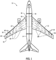
- FIG. 1 Various components of aircraft 10, such as, but not limited to, wings 12 and fuselage 14, are formed from structural components that include at least one hat stringer 50. It should be understood, however, that the disclosure applies equally to other vehicles, including but not limited to automobiles, heavy work vehicles, aquatic vessels, and other vehicles.
- a plurality of first closeout openings 76 are defined in, and extend through, opposing web portions 54 of hat stringer closeout portion 68. In alternative embodiments, plurality of first closeout openings 76 additionally or alternatively are defined in, and extend through, cap portion 56 of closeout portion 68. In other alternative embodiments, plurality of first closeout openings 76 are not defined in any of web portions 54 and cap portion 56. Also in the illustrated embodiment, a plurality of second closeout openings 78 are defined in, and extend through, opposing web portions 54 and cap portion 56 of closeout portion 68. In alternative embodiments, plurality of second closeout openings 78 are not defined in at least one of web portions 54 and cap portion 56. Plurality of first closeout openings 76 and plurality of second closeout openings 78 are configured for coupling closeout portion 68 to a closeout fitting 100 (shown in FIGS. 4 and 5 ), as will be described herein.
- first cover openings 144 are defined in, and extend through, cover 130.
- Each first cover opening 144 is configured to align with a corresponding first closeout opening 76 (shown in FIG. 2 ) when cover 130 is positioned for coupling to closeout portion 68.
- first cover openings are defined in each opposing cover side 136.
- plurality of first cover openings 144 additionally or alternatively are defined in, and extend through, cover cap 140. In other alternative embodiments, first cover openings 144 are not defined in cover 130.
- aligned first insert openings 114 and first cover openings 144, as well as aligned third insert openings 116 and third cover openings 148, are fully accessible externally to closeout fitting 100 to enable installation of corresponding first fasteners 170 and third fasteners 172.
- each of first outer perimeter surface 103 and second outer perimeter surface 105 extends from a first end 120 to a second end 122, with second end 122 configured to face channel 60 when closeout fitting 100 is coupled to hat stringer 50.
- Wall 118 is positioned proximate second end 122 such that, when cover 130 and insert 102 are positioned for coupling to closeout portion 68 and corresponding first fasteners 170 and third fasteners 172 are inserted, both ends of each first fastener 170 and each third fastener 172 are accessible externally to closeout fitting 100 to facilitate completion of the coupling process.
- first fasteners 170 and third fasteners 172 can be installed without a need for access to an interior of hat stringer 50.
Landscapes
- Engineering & Computer Science (AREA)
- Aviation & Aerospace Engineering (AREA)
- Mechanical Engineering (AREA)
- Connection Of Plates (AREA)
- Moulding By Coating Moulds (AREA)
- Cooling, Air Intake And Gas Exhaust, And Fuel Tank Arrangements In Propulsion Units (AREA)
Description
- The field of the disclosure relates generally to hat stringer fittings, and, more particularly, to a closeout fitting for a hat stringer that includes a trimmed end.
- At least some known structures, such as aircraft, include structural components that are stiffened with hat stringers. At least some such hat stringers are trimmed proximate an end of the hat stringer, sometimes referred to as a "run-out" trim. For example, a run-out trim may be necessary to accommodate a structural joint fitting with another structural component. However, such a run-out trim may decrease a capability of at least some known hat stringers to carry certain loads to which the hat stringer may be subjected, such as, but not limited to, torsional loads on the hat stringer and shear loads in a cap of the hat stringer. As a result, adverse effects, such as, but not limited to, excessive hat stringer web bending and excessive localized loads on the hat stringer noodle, such as bending, torsion, shear, axial, vertical, and/or transverse localized noodle loads, may cause a crack or delamination near the run-out trim location.
- Moreover, at least some known structural components include hat stringers that additionally or alternatively provide a vent path for a fluid, such as but not limited to an aircraft fuel and/or fuel vapor, associated with the structural component. To accommodate a vent system connection, an additional hole must be drilled through at least some such hat stringers at a location away from the run-out trim. However, such an additional hole may decrease a structural integrity of at least some known hat stringers. In addition, for at least some known hat stringers, a number of tasks must be performed to seal the vent path proximate a run-out trim as part of a larger process of coupling the structural component, for example an aircraft wing, to another structural component, for example an aircraft fuselage. Thus a time and a cost of the larger process is increased.
-
WO2012/101439 teaches a stringer adapted to transport fluid in an aircraft wing. The stringer may be adapted to provide venting to one or more fuel tanks in the aircraft wing, or may be adapted to provide fuel to the one or more fuel tanks. To perform this function, the stringer comprises a duct member providing a duct and a structural member providing an attachment surface for attachment of the stringer to a wing panel. Typically, the stringer is formed from a composite material such as carbon fibre reinforced plastic. A method of manufacturing such a stringer is also disclosed. - In one aspect, there is described a closeout fitting for a hat stringer. The hat stringer comprises a pair of opposing flange portions, a pair of opposing web portions and a cap portion that extends between the web portions, each web portion extending between the flange portions and an edge of the cap portion, a closeout portion being defined proximate a gap defined in the cap portion, a channel having an interior surface being defined by the web portions and the cap portion, and an outer surface being defined by the web portions and the cap portion. The closeout fitting comprises a cover and an insert. The cover comprises a fitting surface that is substantially complementary to at least a portion of the outer surface of the hat stringer, wherein the cover is configured to couple against the hat stringer outer surface. The cover also comprises a first portion configured to extend across the gap defined in the cap portion of the hat stringer when the cover is coupled against the closeout portion of the hat stringer. The insert comprises a first outer perimeter surface that is substantially complementary to at least a portion of the interior surface of the channel of the hat stringer and a second outer perimeter surface that is substantially complementary to at least a portion of the fitting surface of the cover. The insert is configured to couple against the channel interior surface proximate the hat stringer closeout portion. The insert is configured to couple to the cover. The insert and the cover are formed with a suitable stiffness to limit torsional and/or bending deformation in the web portions of the hat stringer proximate the closeout portion when the closeout fitting is coupled to the closeout portion. The insert further comprises a wall that is sealingly enclosed by the first and second outer perimeter surfaces of the insert and is configured to block flow communication through an end of the channel of the hat stringer when the insert is coupled to the closeout portion.
- In another aspect, there is described a method of making a closeout fitting for a hat stringer of a vehicle. The method comprises: (a) forming a fitting surface of a cover to be substantially complementary to at least a portion of an outer surface of the hat stringer, such that the cover is configured to couple against the hat stringer outer surface; (b) configuring a first portion of the cover to extend across a gap defined in a cap portion of the hat stringer when the cover is coupled against a closeout portion of the hat stringer; and (c) forming a first outer perimeter surface of an insert to be substantially complementary to at least a portion of an interior surface of a channel defined by the hat stringer and forming a second outer perimeter surface of the insert to be substantially complementary to at least a portion of the fitting surface of the cover, such that the insert is configured to couple against the channel interior surface proximate the hat stringer closeout portion. The insert is configured to couple to the cover; the insert and the cover are configured for coupling to the hat stringer closeout portion; the insert and the cover are formed with a suitable stiffness to limit torsional and/or bending deformation in web portions of the hat stringer proximate the closeout portion when the closeout fitting is coupled to the closeout portion; and the insert further comprises a wall that is sealingly enclosed by the first and second outer perimeter surfaces of the insert and is configured to block flow communication through an end of the channel of the hat stringer when the insert is coupled to the closeout portion.
-
-
FIG. 1 is a schematic diagram of an exemplary aircraft on which embodiments of a hat stringer closeout fitting may be used; -
FIG. 2 is a schematic perspective view of an exemplary embodiment of a hat stringer that may be used on the exemplary aircraft shown inFIG. 1 : -
FIG. 3 is a schematic cross-sectional view of the exemplary hat stringer shown inFIG. 2 ; -
FIG. 4 is a schematic exploded perspective view of an exemplary embodiment of a hat stringer closeout fitting that may be used with the hat stringer shown inFIG. 2 and the aircraft shown inFIG. 1 ; -
FIG. 5 is a schematic perspective view of the exemplary hat stringer closeout fitting shown inFIG. 4 coupled to the hat stringer shown inFIG. 2 : -
FIG. 6 is a schematic perspective view of a portion of a side-of-body joint of the exemplary aircraft shown inFIG. 1 , with the exemplary hat stringer shown inFIG. 2 coupled to a wing of the exemplary aircraft and the exemplary hat stringer closeout fitting shown inFIG. 4 coupled to the exemplary hat stringer; and -
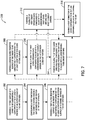
FIG. 7 is a flowchart of an embodiment of a method of making a closeout fitting for a hat stringer, such as the exemplary hat stringer closeout fitting shown inFIG. 4 . - Embodiments of the system and method described herein provide a closeout fitting for a hat stringer closeout portion, such as a closeout portion defined by a run-out trim. The closeout fitting improves a capability of the hat stringer at the trimmed location to carry loads to which the hat stringer is subjected. In certain embodiments, the closeout fitting additionally includes a vent connector configured to couple a channel defined by the hat stringer in flow communication with a vent system.
- Referring more particularly to the drawings, implementations of the disclosure may be described in the context of a structure such as an
exemplary aircraft 10 shown schematically inFIG. 1 . Various components ofaircraft 10, such as, but not limited to,wings 12 andfuselage 14, are formed from structural components that include at least one hat stringer 50. It should be understood, however, that the disclosure applies equally to other vehicles, including but not limited to automobiles, heavy work vehicles, aquatic vessels, and other vehicles. - In the illustrated embodiment, for example, at least one
hat stringer 50 is disposed along an interior of eachwing 12. Eachhat stringer 50 extends from afirst end 51 to asecond end 53. In the illustrated embodiment, eachfirst end 51 is located near atip 16 ofwing 12, and eachsecond end 53 is located near aroot 18 ofwing 12. In alternative embodiments, at least one offirst end 51 andsecond end 53 are located at a different location alongwing 12 for at least one of the at least onehat stringers 50. - Also in the illustrated embodiment, at least one
fuel tank 30 is disposed in an interior of eachwing 12. Additionally or alternatively, at least onefuel tank 30 is disposed in an interior offuselage 14. Eachfuel tank 30 is in flow communication with at least onevent 32 ofaircraft 10. The at least onevent 32 facilitates reducing a pressure difference between an interior of eachfuel tank 30 and an atmospheric pressure. -
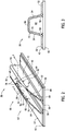
FIG. 2 is a schematic perspective view of an exemplary embodiment ofhat stringer 50, andFIG. 3 is a schematic cross-sectional view ofexemplary hat stringer 50 taken along line 3-3 shown inFIG. 2 . With reference toFIGS. 2 and 3 ,hat stringer 50 includes a pair ofopposing flange portions 52, a pair ofopposing web portions 54, and acap portion 56 that extends betweenweb portions 54. Eachweb portion 54 extends between one of the pair offlange portions 52 and an edge ofcap portion 56. In an embodiment,hat stringer 50 is formed from a carbon fiber reinforced polymer material. In alternative embodiments,hat stringer 50 is formed from any other suitable material that enables hat stringer 50 to function as described herein. - In the illustrated embodiment,
hat stringer 50 is coupled to asurface 42 of apanel 40. For example,panel 40 is a skin panel of wing 12 (shown inFIG. 1 ), andsurface 42 is an interior surface of the skin panel. More specifically, eachflange portion 52 ofhat stringer 50 is coupled tosurface 42 in any suitable fashion, such as but not limited to by an adhesive or co-bonding, that enables hat stringer 50 to function as described herein. Anoodle 58 also is coupled in any suitable fashion betweensurface 42 and hat stringer 50 at each location where one of theflange portions 52 transitions into one of theweb portions 54. In alternative embodiments,noodles 58 are not present. -
Web portions 54,cap portion 56,panel 40, and, if present,noodles 58 cooperate to define achannel 60 having aninterior surface 70. In the illustrated embodiment, channelinterior surface 70 has a generally trapezoidal cross-section. In alternative embodiments, channelinterior surface 70 has a cross-section that is other than generally trapezoidal. In addition,web portions 54 andcap portion 56 cooperate to define anouter surface 72 ofhat stringer 50. - In certain embodiments,
channel 60 is configured to be in flow communication with a venting system. For example,channel 60 is configured to be in flow communication with at least onefuel tank 30 and at least onevent 32 of aircraft 10 (shown inFIG. 1 ) to facilitate reducing a pressure difference between an interior of the at least onefuel tank 30 and an atmospheric pressure. In alternative embodiments,channel 60 is not configured to be in flow communication with a venting system. - With reference to
FIG. 2 , in the illustrated embodiment, a run-out trim 62 ofhat stringer 50 is defined proximate to one offirst end 51 andsecond end 53 ofhat stringer 50. More specifically, run-out trim 62 is defined by a region in which material has been trimmed fromhat stringer 50 along anedge 64 of eachweb portion 54 and along anedge 66 ofcap portion 56. In certain embodiments, a shape and location ofedges panel 40 with another structural component. For example,panel 40 is a skin panel of wing 12 (shown inFIG. 1 ), and end 44 is proximate root 18 (shown inFIG. 1 ) and configured to be coupled tofuselage 14 via a structural joint, such as joint 90 (shown inFIG. 6 ). - A
gap 69 is defined in hatstringer cap portion 56 between opposing web portion edges 64 and between opposing portions ofcap edge 66. Acloseout portion 68 ofhat stringer 50 is definedproximate gap 69. Afirst end 61 ofchannel 60 is definedadjacent closeout portion 68. - A plurality of
first closeout openings 76 are defined in, and extend through, opposingweb portions 54 of hatstringer closeout portion 68. In alternative embodiments, plurality offirst closeout openings 76 additionally or alternatively are defined in, and extend through,cap portion 56 ofcloseout portion 68. In other alternative embodiments, plurality offirst closeout openings 76 are not defined in any ofweb portions 54 andcap portion 56. Also in the illustrated embodiment, a plurality ofsecond closeout openings 78 are defined in, and extend through, opposingweb portions 54 andcap portion 56 ofcloseout portion 68. In alternative embodiments, plurality ofsecond closeout openings 78 are not defined in at least one ofweb portions 54 andcap portion 56. Plurality offirst closeout openings 76 and plurality ofsecond closeout openings 78 are configured forcoupling closeout portion 68 to a closeout fitting 100 (shown inFIGS. 4 and 5 ), as will be described herein. -
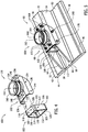
FIG. 4 is a schematic exploded perspective view of an exemplary embodiment of closeout fitting 100.FIG. 5 is a schematic perspective view of exemplary closeout fitting 100 coupled to hatstringer closeout portion 68. With reference toFIGS. 4 and 5 , closeout fitting 100 includes aninsert 102 and acover 130.Insert 102 and cover 130 are configured to couple tocloseout portion 68 such thatinsert 102 and cover 130 provide a structural path for reacting loads to whichhat stringer 50 is subjected. In certain embodiments, insert 102 and cover 130 are formed with a suitable stiffness to limit a deformation ofhat stringer 50proximate closeout portion 68 when closeout fitting 100 is coupled tocloseout portion 68.Insert 102 and cover 130 are formed with a suitable stiffness to limit a torsional and/or bending deformation inweb portions 54proximate closeout portion 68.Insert 102 and cover 130 may also be formed with a suitable stiffness to limit a deformation from shear loads in hatstringer cap portion 56 proximatecap portion edge 66. In an embodiment, insert 102 and cover 130 are formed from a metallic material. In alternative embodiments, insert 102 and cover 130 are formed from any suitable material that enables closeout fitting 100 to function as described herein. - Cover 130 defines a
fitting surface 134 that is substantially complementary to at least a portion of hat stringerouter surface 72, such thatcover 130 is configured to couple againstouter surface 72. In the illustrated embodiment,cover 130 includes a pair of opposingsides 136 that are each substantially complementary to an outer surface of at least a portion of a respective hatstringer web portion 54, and acap 140 that is substantially complementary to an outer surface of hatstringer cap portion 56. Cover 130 includes at least afirst portion 132 configured to extend acrossgap 69 whencover 130 is coupled against hat stringerouter surface 72 atcloseout portion 68. - In the illustrated embodiment, a plurality of
first cover openings 144 are defined in, and extend through,cover 130. Each first cover opening 144 is configured to align with a corresponding first closeout opening 76 (shown inFIG. 2 ) whencover 130 is positioned for coupling to closeoutportion 68. In the illustrated embodiment, first cover openings are defined in each opposingcover side 136. In alternative embodiments, plurality offirst cover openings 144 additionally or alternatively are defined in, and extend through,cover cap 140. In other alternative embodiments,first cover openings 144 are not defined incover 130. - Also in the illustrated embodiment, a plurality of
second cover openings 154 are defined in, and extend through,cover 130. Each second cover opening 154 is configured to align with a corresponding second closeout opening 78 (shown inFIG. 2 ) whencover 130 is positioned for coupling to closeoutportion 68. In the illustrated embodiment,second cover openings 154 are defined in each opposingcover side 136 andcover cap 140. In alternative embodiments,second cover openings 154 are not defined in at least one of opposingcover sides 136 andcover cap 140. When closeout fitting 100 is assembled, a suitablesecond fastener 168 is disposed in each corresponding aligned second closeout opening 78 and second cover opening 154 tocouple cover 130 tocloseout portion 68. In alternative embodiments,second cover openings 154 are not defined incover 130, and insert 102 and cover 130 are coupled tocloseout portion 68 in another suitable fashion, such as but not limited to by at least one first fastener 170 (as will be described herein) or by an adhesive. - Further in the illustrated embodiment, a plurality of
third cover openings 148 are defined in, and extend through,cover cap 140. Each third cover opening 148 is configured to be positioned proximate gap 69 (shown inFIG. 2 ) whencover 130 is positioned for coupling to closeoutportion 68. Moreover, each third cover opening 148 is configured to align with a corresponding third insert opening 116 ininsert 102, as will be described herein, whencover 130 and insert 102 are positioned for coupling to closeoutportion 68. In alternative embodiments,third cover openings 148 are additionally or alternatively are defined in, and extend through, opposing cover sides 136. In other alternative embodiments,third cover openings 148 are not defined in any of opposingcover sides 136 andcover cap 140. - In certain embodiments,
cover 130 includes avent connector 160. In the illustrated embodiment,vent connector 160 extends fromcover cap 140.Vent connector 160 defines anorifice 162 that extends throughcover cap 140 such thatvent connector 160 is configured to be in flow communication withchannel 60 viagap 69 whencover 130 is positioned for coupling to closeoutportion 68. Arim 164 ofvent connector 160 is configured for coupling to a vent tube 80 (shown inFIG. 6 ) in any suitable fashion, such as but not limited to by a threaded connection. In certain embodiments, venttube 80 is in flow communication with at least one of plurality offuel tanks 30 ofaircraft 10, such thatchannel 60 provides a conduit between the at least onefuel tank 30 and at least onevent 32 ofaircraft 10. In alternative embodiments,cover 130 does not includevent connector 160, and closeout fitting 100 is not configured to couplechannel 60 to a vent system. -
Insert 102 is configured to be positioned at channelfirst end 61 when closeout fitting 100 is positioned for coupling to closeoutportion 68.Insert 102 defines a firstouter perimeter surface 103 that is substantially complementary to at least a portion of channel interior surface 70 (shown inFIG. 3 ), such thatinsert 102 is configured to couple against channelinterior surface 70proximate closeout portion 68.Insert 102 defines a secondouter perimeter surface 105 that is substantially complementary to at least a portion offitting surface 134 ofcover 130. - For example, in the illustrated embodiment, insert 102 includes a pair of opposing
sides 106, acap end 110, and apanel end 112opposite cap end 110. Firstouter perimeter surface 103 is defined by opposing insert sides 106 that are each substantially complementary to an inner surface of a respective hatstringer web portion 54, and insertpanel end 112 that is substantially complementary to a portion ofpanel surface 42 that extends betweenweb portions 54.Insert panel end 112 also is substantially complementary to a surface ofnoodles 58, if present. Also in the illustrated embodiment, secondouter perimeter surface 105 is defined byinsert cap end 110.Insert cap end 110 is configured to be positionedproximate gap 69 wheninsert 102 is positioned for coupling to closeoutportion 68, and insertcap end 110 is substantially complementary tofitting surface 134 offirst portion 132 ofcover 130. - In an alternative embodiment (not shown), first
outer perimeter surface 103 also is partially defined byinsert cap end 110. For example, insertcap end 110 is configured to be positioned proximate hatstringer cap portion 56 wheninsert 110 is positioned for coupling to closeoutportion 68, and insertcap end 110 is substantially complementary to an inner surface ofcap portion 56. -
Insert 102 is configured to block flow communication throughfirst end 61 ofchannel 60 wheninsert 102 is coupled to closeout portion 68 (shown inFIG. 2 ). For example, in certain embodiments, insert 102 includes awall 118 that is sealingly enclosed by firstouter perimeter surface 103 and secondouter perimeter surface 105. In the illustrated embodiment,wall 118 extends between opposing insert sides 106 and extends betweeninsert cap end 110 and insertpanel end 112. In alternative embodiments,wall 118 is sealingly enclosed substantially entirely by firstouter perimeter surface 103. - A plurality of
first insert openings 114 are defined in, and extend through, firstouter perimeter surface 103. Eachfirst insert opening 114 is configured to align with a correspondingfirst closeout opening 76 and a corresponding first cover opening 144 wheninsert 102 and cover 130 are positioned for coupling to closeoutportion 68. In the illustrated embodiment,first insert openings 114 are defined in each opposinginsert side 106. In alternative embodiments, plurality offirst insert openings 114 additionally or alternatively are defined in, and extend through, insertcap end 110. When closeout fitting 100 is assembled, a suitablefirst fastener 170 is disposed in each corresponding alignedfirst insert opening 114,first closeout opening 76, and first cover opening 144 to couple insert 102 and cover 130 tocloseout portion 68. In alternative embodiments,first insert openings 114 are not defined in firstouter perimeter surface 103, and insert 102 and cover 130 are coupled tocloseout portion 68 in another suitable fashion, such as but not limited to bysecond fasteners 168 and third fasteners 172 (as will be described herein) or by an adhesive. - Also in the illustrated embodiment, a plurality of
third insert openings 116 are defined in, and extend through, secondouter perimeter surface 105. Plurality ofthird insert openings 116 are configured to be positioned proximate gap 69 (shown inFIG. 2 ) wheninsert 102 is positioned for coupling to closeoutportion 68. Moreover, each third insert opening 116 is configured to align with a corresponding third cover opening 148 whencover 130 and insert 102 are positioned for coupling to closeoutportion 68. In the illustrated embodiment,third insert openings 116 are defined ininsert cap end 110. In alternative embodiments,third insert openings 116 additionally or alternatively are defined in, and extend through, opposing insert sides 106. When closeout fitting 100 is assembled, a suitablethird fastener 172 is disposed in each corresponding aligned third insert opening 116 and third cover opening 148 to couple insert 102 to cover 130, and thus, indirectly, to closeoutportion 68. In other alternative embodiments,third insert openings 116 are not defined in secondouter perimeter surface 105, and insert 102 is coupled to cover 130 in another suitable fashion, such as but not limited to byfirst fasteners 170 and/or by an adhesive. - In certain embodiments, aligned
first insert openings 114 andfirst cover openings 144, as well as alignedthird insert openings 116 andthird cover openings 148, are fully accessible externally to closeout fitting 100 to enable installation of correspondingfirst fasteners 170 andthird fasteners 172. For example, in the illustrated embodiment, each of firstouter perimeter surface 103 and secondouter perimeter surface 105 extends from afirst end 120 to asecond end 122, withsecond end 122 configured to facechannel 60 when closeout fitting 100 is coupled tohat stringer 50.Wall 118 is positioned proximatesecond end 122 such that, whencover 130 and insert 102 are positioned for coupling to closeoutportion 68 and correspondingfirst fasteners 170 andthird fasteners 172 are inserted, both ends of eachfirst fastener 170 and eachthird fastener 172 are accessible externally to closeout fitting 100 to facilitate completion of the coupling process. Thus, each offirst fasteners 170 andthird fasteners 172 can be installed without a need for access to an interior ofhat stringer 50. In alternative embodiments, at least one of alignedfirst insert openings 114 andfirst cover openings 144 and alignedthird insert openings 116 andthird cover openings 148 are not fully accessible externally to closeout fitting 100 to enable installation of correspondingfirst fasteners 170 andthird fasteners 172, and the correspondingfirst fasteners 170 andthird fasteners 172 are installed by, for example, accessing a second end of the fasteners throughorifice 162. - As described above, insert 102 is configured to substantially block flow communication through channel first end 61 (shown in
FIG. 2 ) when closeout fitting 100 is coupled tocloseout portion 68. In particular embodiments, a suitable sealant material is positioned betweeninsert 102 and at least one ofcloseout portion 68 and cover 130 to improve a sealing effectiveness ofinsert 102 at channelfirst end 61. For example, the sealant material is positioned at an interface betweeninsert 102 and at least one of hat stringer web portion edges 64 and coverfirst portion 132. In alternative embodiments, no sealant material is positioned betweeninsert 102 and either ofcloseout portion 68 andcover 130. -
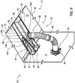
FIG. 6 is a schematic perspective view of a portion of a side-of-body joint 90coupling wing 12 andfuselage 14 ofaircraft 10, withhat stringer 50 coupled towing 12 and closeout fitting 100 coupled tohat stringer 50. In the illustrated embodiment,panel 40 is an upper wing skin panel, andsurface 42 is an interior surface ofpanel 40. Thus, as illustrated inFIG. 6 , hat stringerouter surface 72 extends downward fromsurface 42. Joint 90 includes at least onestructural fitting 92 that coupleshat stringer 50 tofuselage 14. In the illustrated embodiment, the at least onestructural fitting 92 includes a pair of structuralfitting web portions 94, and each structuralfitting web portion 94 is coupled to a corresponding hatstringer flange portion 52 andweb portion 54 in any suitable fashion, such as but not limited to using suitable fasteners (not shown). - In the illustrated embodiment,
hat stringer channel 60 is coupled in flow communication with at least one fuel tank 30 (shown inFIG. 1 ) and at least one vent 32 (shown inFIG. 1 ) ofaircraft 10. More specifically, afirst end 82 ofvent tube 80 is coupled in flow communication with closeoutfitting vent connector 160, and asecond end 84 ofvent tube 80 is coupled in flow communication with avent port 86 offuselage 14.Vent port 86 is in flow communication with at least onefuel tank 30 located in an interior offuselage 14. Thus, a fluid flow path is defined from the at least onefuel tank 30, throughvent port 86, throughvent tube 80, through closeoutfitting vent connector 160, through gap 69 (shown inFIG. 2 ), through channel 60 (shown inFIG. 2 ), to the at least onevent 32. Moreover, the flow path is at least partially defined at channelfirst end 61 by insert 102 (visible inFIG. 5 ) of closeout fitting 100. In an alternative embodiment, closeout fitting 100 does not includevent connector 160, andhat stringer channel 60 is not coupled in flow communication with anyfuel tank 30 and/or anyvent 32. -
FIG. 7 is a flowchart of an embodiment of amethod 200 of making a closeout fitting, such as closeout fitting 100, for a hat stringer, such ashat stringer 50, of a vehicle, such asaircraft 10.Method 200 includes forming 202 a fitting surface of a cover, such asfitting surface 134 ofcover 130, to be substantially complementary to at least a portion of an outer surface, such asouter surface 72, of the hat stringer, such that the cover is configured to couple against the hat stringer outer surface.Method 200 also includes configuring 204 a first portion, such asfirst portion 132, of the cover to extend across a gap defined in a cap portion, such asgap 69 defined incap portion 56, of the hat stringer when the cover is coupled against a closeout portion, such ascloseout portion 68, of the hat stringer.Method 200 further includes forming 206 a first outer perimeter surface of an insert, such as first perimeterouter surface 103 ofinsert 102, to be substantially complementary to at least a portion of an interior surface of a channel defined by the hat stringer, such asinterior surface 70 ofchannel 60, such that the insert is configured to couple against the channel interior surface proximate the hat stringer closeout portion. The insert and the cover are formed with a suitable stiffness to limit a deformation of the hat stringer proximate the closeout portion when the closeout fitting is coupled to the closeout portion. - In certain embodiments,
method 200 includes forming 208 a second outer perimeter surface of the insert, such as secondouter perimeter surface 105, to be substantially complementary to at least a portion of the cover fitting surface. In some embodiments,method 200 also includes forming 210 a plurality of first cover openings, such asfirst cover openings 144, in the cover. Each first cover opening extends through the cover, and each first cover opening is configured to align with a corresponding one of a plurality of first closeout openings, such asfirst closeout openings 76, defined in the hat stringer closeout portion when the cover is positioned for coupling to the hat stringer closeout portion. Also in some embodiments,method 200 includes forming 212 a plurality of first insert openings, such asfirst insert openings 114, in the first outer perimeter surface. Each first insert opening extends through the first outer perimeter surface, and each first insert opening is configured to align with a corresponding one of the plurality of first cover openings and a corresponding one of the plurality of first closeout openings when the insert and the cover are positioned for coupling to the hat stringer closeout portion. - Additionally, in certain embodiments,
method 200 includes forming 214 a plurality of third cover openings, such asthird cover openings 148, in the cover. Each third cover opening extends through the cover, and each third cover opening is configured to be positioned proximate the gap when the cover is positioned for coupling to the hat stringer closeout portion. Each third cover opening is configured to align with a corresponding one of a plurality of third insert openings, such asthird insert openings 116, defined in the insert when the cover and the insert are positioned for coupling to the hat stringer closeout portion. In some embodiments,method 200 includes forming 216 a vent connector, such asvent connector 160, of the cover. The vent connector defines an orifice, such asorifice 162, that extends through the cover such that the vent connector is configured to be in flow communication with the channel via the gap when the cover is positioned for coupling to the hat stringer closeout portion. - Each of the processes of
method 200 may be performed or carried out by a system integrator, a third party, and/or a customer. For the purposes of this description, a system integrator may include without limitation any number of aircraft manufacturers and major-system subcontractors; a third party may include without limitation any number of venders, subcontractors, and suppliers; and a customer may be an airline, leasing company, military entity, service organization, and so on. Moreover, although an aerospace example is shown, the principles of the invention may be applied to other industries, such as the automotive industry. - The embodiments described herein provide a closeout fitting for a hat stringer closeout portion, such as a closeout portion defined by a run-out trim. The embodiments improve a capability of the hat stringer at the trimmed location to carry loads to which the hat stringer is subjected. Certain embodiments additionally provide a vent connector configured to couple a channel defined by the hat stringer in flow communication with a vent system.
- The embodiments described herein provide improvements over at least some structures that include hat stringer run-out trims. As compared to at least some known structures, the closeout fitting described herein reduces or eliminates adverse structural effects proximate a hat stringer run-out trim such as, but not limited to, excessive hat stringer web bending and excessive localized loads on the hat stringer noodle, such as bending, torsion, shear, axial, vertical, and/or transverse localized noodle loads. In addition, in certain embodiments, the closeout fitting includes a vent connector that eliminates a need for an additional hole in the hat stringer to couple a channel defined by the hat stringer in flow communication with a vent system. Moreover, the closeout fitting can be coupled to the hat stringer closeout portion, and additionally a simple vent system connection can established, prior to initiation of a larger coupling process involving the associated structure, such as a wing-to-fuselage coupling process. Thus, the embodiments described herein facilitate reducing a number of tasks associated with a critical stage in an overall manufacturing process.
- This written description uses examples to disclose various implementations, which include the best mode, to enable any person skilled in the art to practice those implementations, including making and using any devices or systems and performing any incorporated methods. The patentable scope is defined by the appended claims.
Claims (10)
- A closeout fitting (100) for a hat stringer (50), wherein the hat stringer comprises a pair of opposing flange portions (52), a pair of opposing web portions (54) and a cap portion (56) that extends between the web portions, each web portion extending between the flange portions and an edge of the cap portion, a closeout portion (68) being defined proximate a gap (69) defined in the cap portion, a channel (60) having an interior surface (70) being defined by the web portions and the cap portion, and an outer surface (72) being defined by the web portions and the cap portion, said closeout fitting comprising:a cover (130), comprising:a fitting surface (134) that is substantially complementary to at least a portion of the outer surface of the hat stringer, wherein said cover is configured to couple against said hat stringer outer surface; anda first portion (132) configured to extend across the gap defined in the cap portion of the hat stringer when said cover is coupled against the closeout portion of the hat stringer; andan insert (102) comprising a first outer perimeter surface (103) that is substantially complementary to at least a portion of the interior surface (70) of the channel (60) of the hat stringer and a second outer perimeter surface (105) that is substantially complementary to at least a portion of the fitting surface (134) of the cover, wherein said insert is configured to couple against said channel interior surface proximate the hat stringer closeout portion, and wherein said insert is configured to couple to the cover,wherein said insert and said cover are formed with a suitable stiffness to limit torsional and/or bending deformation in the web portions of the hat stringer proximate the closeout portion when said closeout fitting is coupled to the closeout portion, whereinthe insert further comprises a wall (118) that is sealingly enclosed by said first and second outer perimeter surfaces of said insert and is configured to block flow communication through an end of the channel of the hat stringer when the insert is coupled to the closeout portion.
- The closeout fitting according to claim 1, wherein said cover further comprises a plurality of first cover openings (144) defined in said cover and extending therethrough, each said first cover opening is configured to align with a corresponding one of a plurality of first closeout openings (76) defined in the hat stringer closeout portion when said cover is positioned for coupling to the hat stringer closeout portion.
- The closeout fitting according to Claim 2, wherein said insert further comprises a plurality of first insert openings (114) defined in said first outer perimeter surface (103) and extending therethrough, each said first insert opening (114) is configured to align with a corresponding said first cover opening (144) and a corresponding said first closeout opening (76) when said insert and said cover are positioned for coupling to the hat stringer closeout portion.
- The closeout fitting according to any preceding claim, wherein said cover further comprises a plurality of third cover openings (148) defined in said cover and extending therethrough, each said third cover opening (148) is configured to be positioned proximate the gap when said cover is positioned for coupling to the hat stringer closeout portion, each said third cover opening is configured to align with a corresponding one of a plurality of third insert openings defined in said insert when said cover and said insert are positioned for coupling to the hat stringer closeout portion.
- The closeout fitting according to any preceding claim, wherein said cover further comprises a vent connector (160), said vent connector defines an orifice (162) that extends through said cover such that said vent connector is configured to be in flow communication with the channel via the gap when said cover is positioned for coupling to the hat stringer closeout portion.
- A method of making a closeout fitting (100) for a hat stringer (50) of a vehicle, said method comprising:forming a fitting surface (134) of a cover (130) to be substantially complementary to at least a portion of an outer surface (72) of the hat stringer, such that the cover (130) is configured to couple against the hat stringer outer surface (72);configuring a first portion (132) of the cover (130) to extend across a gap (69) defined in a cap portion (56) of the hat stringer when the cover is coupled against a closeout portion (68) of the hat stringer; andforming a first outer perimeter surface (103) of an insert (102) to be substantially complementary to at least a portion of an interior surface (70) of a channel (60) defined by the hat stringer (50) and forming a second outer perimeter surface of the insert (102) to be substantially complementary to at least a portion of the fitting surface (134) of the cover, such that the insert (102) is configured to couple against the channel interior surface (70) proximate the hat stringer closeout portion (68), wherein said insert is configured to couple to the cover, wherein the insert (102) and the cover (130) are configured for coupling to the hat stringer closeout portion (68), and wherein the insert and the cover are formed with a suitable stiffness to limit torsional and/or bending deformation in web portions of the hat stringer proximate the closeout portion when the closeout fitting is coupled to the closeout portion, and wherein the insert further comprises a wall (118) that is sealingly enclosed by said first and second outer perimeter surfaces of said insert and is configured to block flow communication through an end of the channel of the hat stringer when the insert is coupled to the closeout portion.
- The method according to Claim 6, further comprising forming a plurality of first cover openings (144) in the cover, wherein each first cover opening extends through the cover, each first cover opening is configured to align with a corresponding one of a plurality of first closeout openings defined in the hat stringer closeout portion when the cover is positioned for coupling to the hat stringer closeout portion.
- The method according to Claim 7, further comprising forming a plurality of first insert openings (114) in the first outer perimeter surface, wherein each first insert opening extends through the first outer perimeter surface, each first insert opening is configured to align with a corresponding one of the plurality of first cover openings and a corresponding one of the plurality of first closeout openings when the insert and the cover are positioned for coupling to the hat stringer closeout portion.
- The method according to any of Claims 6-8, further comprising forming a plurality of third cover openings (148) in the cover, wherein each third cover opening extends through the cover, each third cover opening is configured to be positioned proximate the gap when the cover is positioned for coupling to the hat stringer closeout portion, and each third cover opening is configured to align with a corresponding one of a plurality of third insert openings defined in the insert when the cover and the insert are positioned for coupling to the hat stringer closeout portion.
- The method according to any of Claims 6-9, further comprising forming a vent connector (160) of the cover, wherein the vent connector defines an orifice (162) that extends through the cover such that the vent connector is configured to be in flow communication with the channel via the gap when the cover is positioned for coupling to the hat stringer closeout portion.
Applications Claiming Priority (1)
| Application Number | Priority Date | Filing Date | Title |
|---|---|---|---|
| US14/464,098 US9399510B2 (en) | 2014-08-20 | 2014-08-20 | Hat stringer closeout fitting and method of making same |
Publications (2)
| Publication Number | Publication Date |
|---|---|
| EP2987720A1 EP2987720A1 (en) | 2016-02-24 |
| EP2987720B1 true EP2987720B1 (en) | 2019-11-06 |
Family
ID=53540629
Family Applications (1)
| Application Number | Title | Priority Date | Filing Date |
|---|---|---|---|
| EP15175417.3A Active EP2987720B1 (en) | 2014-08-20 | 2015-07-06 | Hat stringer closeout fitting and method of making same |
Country Status (5)
| Country | Link |
|---|---|
| US (1) | US9399510B2 (en) |
| EP (1) | EP2987720B1 (en) |
| JP (1) | JP6637694B2 (en) |
| CN (1) | CN105383682B (en) |
| CA (1) | CA2891878C (en) |
Families Citing this family (20)
| Publication number | Priority date | Publication date | Assignee | Title |
|---|---|---|---|---|
| USD799690S1 (en) * | 2014-12-22 | 2017-10-10 | Ebara Corporation | Inner cylinder for exhaust gas treatment apparatus |
| CA168044S (en) * | 2015-10-20 | 2017-01-09 | Kimura Kohki Co | Air-conditioning outlet |
| JP1560177S (en) * | 2015-10-20 | 2016-10-03 | ||
| JP1560175S (en) * | 2015-10-20 | 2016-10-03 | ||
| CA171067S (en) * | 2015-10-20 | 2017-01-09 | Kimura Kohki Co | Air-conditioning outlet |
| CA171066S (en) * | 2015-10-20 | 2017-01-09 | Kimura Kohki Co | Air-conditioning outlet |
| EP3625122B1 (en) * | 2017-05-18 | 2024-08-28 | BAE Systems PLC | Door assembly for a vehicle |
| EP3403917A1 (en) * | 2017-05-18 | 2018-11-21 | BAE SYSTEMS plc | Door assembly for a vehicle |
| GB2575105A (en) * | 2018-06-29 | 2020-01-01 | Airbus Operations Ltd | A duct stringer |
| GB2575106B (en) * | 2018-06-29 | 2020-09-02 | Airbus Operations Ltd | A duct stringer |
| GB2575102A (en) * | 2018-06-29 | 2020-01-01 | Airbus Operations Ltd | Duct stringer with bulkhead |
| GB2575103A (en) | 2018-06-29 | 2020-01-01 | Airbus Operations Ltd | Method of manufacturing duct stringer |
| GB2575280A (en) * | 2018-07-04 | 2020-01-08 | Airbus Operations Ltd | A Connector |
| CN109911176A (en) * | 2019-03-20 | 2019-06-21 | 成都飞机工业(集团)有限责任公司 | A kind of integral wing tank area flexible connection dry catheter structure |
| US11794874B2 (en) * | 2019-10-23 | 2023-10-24 | The Boeing Company | Low impact hat stringer fluid dam |
| GB2590477A (en) * | 2019-12-19 | 2021-06-30 | Airbus Operations Ltd | Duct stringer assembly with bulkhead |
| US11554876B2 (en) * | 2020-03-19 | 2023-01-17 | The Boeing Company | Single piece vent dam |
| DE102021101438B3 (en) * | 2021-01-22 | 2022-01-13 | Airbus Defence and Space GmbH | Connector for a structure-integrated line system |
| US11718384B2 (en) | 2021-07-30 | 2023-08-08 | The Boeing Company | Hat-stringer assemblies for an aircraft and methods of forming same |
| US11597495B2 (en) | 2021-07-30 | 2023-03-07 | The Boeing Company | Vented hat stringers and methods of forming the same |
Family Cites Families (70)
| Publication number | Priority date | Publication date | Assignee | Title |
|---|---|---|---|---|
| US3878356A (en) * | 1973-09-27 | 1975-04-15 | Cleveland E Roye | Diffusion band riveting method |
| US4645244A (en) * | 1984-02-15 | 1987-02-24 | Edwin Curtis | Aircraft duct gimbaled joint |
| US4802642A (en) * | 1986-10-14 | 1989-02-07 | The Boeing Company | Control of laminar flow in fluids by means of acoustic energy |
| JPH0367222U (en) * | 1989-10-25 | 1991-07-01 | ||
| US5263747A (en) * | 1992-02-13 | 1993-11-23 | Titeflex Corporation | Means for and methods of attaching metal hoses to end fittings |
| US5370427A (en) * | 1994-01-10 | 1994-12-06 | General Electric Company | Expansion joint for fluid piping with rotation prevention member |
| DE29823586U1 (en) * | 1998-05-29 | 1999-11-18 | IWK Regler und Kompensatoren GmbH, 76297 Stutensee | Flexible pipe element |
| US6458309B1 (en) * | 1998-06-01 | 2002-10-01 | Rohr, Inc. | Method for fabricating an advanced composite aerostructure article having an integral co-cured fly away hollow mandrel |
| JP4010817B2 (en) * | 2002-01-30 | 2007-11-21 | 本田技研工業株式会社 | Vehicle body frame structure |
| US6814382B2 (en) * | 2002-03-04 | 2004-11-09 | Nishikawa Rubber Co., Ltd. | Car door structure and noise insulation sheet |
| US7040666B2 (en) * | 2003-06-06 | 2006-05-09 | General Electric Company | Full port externally gimballed joint |
| US7325771B2 (en) * | 2004-09-23 | 2008-02-05 | The Boeing Company | Splice joints for composite aircraft fuselages and other structures |
| US7387277B2 (en) * | 2004-12-29 | 2008-06-17 | The Boeing Company | Aircraft wing composed of composite and metal panels |
| US7377598B2 (en) * | 2005-01-10 | 2008-05-27 | American Axle & Manufacturing, Inc. | Axle housing assembly and method |
| USD551336S1 (en) * | 2006-05-08 | 2007-09-18 | Eastern Sheet Metal, Inc. | Duct and seal assembly |
| US7871040B2 (en) * | 2006-11-10 | 2011-01-18 | The Boeing Company | Composite aircraft structures with hat stiffeners |
| US7635106B2 (en) * | 2006-11-30 | 2009-12-22 | The Boeing Company | Composite shear tie |
| US20080169641A1 (en) * | 2007-01-16 | 2008-07-17 | Santa Cruz Cathy D | Inline irrigation pipe adapter fitting and method of installation |
| US20080302912A1 (en) * | 2007-06-08 | 2008-12-11 | The Boeing Company | Bladderless Mold Line Conformal Hat Stringer |
| US8043554B2 (en) * | 2007-06-08 | 2011-10-25 | The Boeing Company | Manufacturing process using bladderless mold line conformal hat stringer |
| DE102007029500B4 (en) * | 2007-06-25 | 2013-02-14 | Airbus Operations Gmbh | Method for coupling stiffening profile elements and structural component |
| US7686387B2 (en) * | 2007-08-28 | 2010-03-30 | Ford Global Technologies, Llc | Reinforcing sleeve for a tubular beam |
| US7828246B2 (en) * | 2007-09-14 | 2010-11-09 | Spectrum Aeronautical, Llc | Wing with sectioned tubular members |
| FR2922517B1 (en) | 2007-10-18 | 2010-04-23 | Airbus France | AIRCRAFT COMPRISING SUNNY ARRESTOR JUNCTIONS AND METHOD OF MANUFACTURING SUCH A PLANE |
| US7879276B2 (en) * | 2007-11-08 | 2011-02-01 | The Boeing Company | Foam stiffened hollow composite stringer |
| US8292214B2 (en) * | 2008-01-18 | 2012-10-23 | The Boeing Company | Vibration damping for wing-to-body aircraft fairing |
| EP2099077A1 (en) * | 2008-03-06 | 2009-09-09 | Inventux Technologies AG | Module for converting solar radiation into electricity |
| US20090266936A1 (en) * | 2008-04-29 | 2009-10-29 | Fernando Ferreira Fernandez | Aircraft fuselage structural components and methods of making same |
| US8465613B2 (en) * | 2011-08-24 | 2013-06-18 | The Boeing Company | Method and apparatus for fabricating variable gauge, contoured composite stiffeners |
| US8293051B2 (en) * | 2008-12-10 | 2012-10-23 | The Boeing Company | Method for producing composite laminates using a collapsible mandrel |
| US9296187B2 (en) * | 2008-12-10 | 2016-03-29 | The Boeing Company | Bagging process and mandrel for fabrication of elongated composite structure |
| US8074694B2 (en) * | 2009-05-28 | 2011-12-13 | The Boeing Company | Stringer transition method |
| US8617687B2 (en) * | 2009-08-03 | 2013-12-31 | The Boeing Company | Multi-functional aircraft structures |
| JP5515510B2 (en) * | 2009-08-21 | 2014-06-11 | 日産自動車株式会社 | Body structure |
| DE102009029575B4 (en) * | 2009-09-18 | 2011-06-22 | Airbus Operations GmbH, 21129 | Method for stiffening a fiber composite component and arrangement for producing a stiffened fiber composite component |
| US8167245B1 (en) * | 2009-11-03 | 2012-05-01 | The Boeing Company | Fuel barrier |
| US9010689B1 (en) * | 2010-01-04 | 2015-04-21 | The Boeing Company | Fluid dynamic vent dam |
| US20130118624A1 (en) * | 2010-03-29 | 2013-05-16 | Hamilton Sundstrand Corporation | Sealed flapper diverter valve |
| US8408493B2 (en) * | 2010-05-19 | 2013-04-02 | The Boeing Company | Composite stringer end trim |
| FR2963273B1 (en) * | 2010-07-29 | 2014-01-03 | Airbus Operations Sas | METHOD FOR MANUFACTURING A RAIDI PANEL IN COMPOSITE MATERIAL |
| GB201012730D0 (en) * | 2010-07-29 | 2010-09-15 | Airbus Operations Ltd | A refuel valve assembly and method for refuelling an aircraft |
| WO2012021283A1 (en) * | 2010-08-13 | 2012-02-16 | Hexcel Corporation | Machinable composite material |
| TW201234041A (en) * | 2010-09-18 | 2012-08-16 | Tonta Electro Optical Co Ltd | Optical device for coupling to a camera lens to form a visual observation system |
| GB201101435D0 (en) | 2011-01-27 | 2011-03-16 | Airbus Uk Ltd | Stringer for an aircraft wing and method of forming thereof |
| US8864181B2 (en) * | 2011-02-16 | 2014-10-21 | Sensus Spectrum, Llc | Split-ring gland pipe coupling with corrugated armor |
| US8777158B2 (en) * | 2011-03-25 | 2014-07-15 | The Boeing Company | Joint sealing system |
| ES2400129B1 (en) * | 2011-05-30 | 2014-06-18 | Airbus Operations, S.L. | METHOD OF MANUFACTURING OF LARGUERILLOS WITH FORM OF "T" WITH A DIFFERENT ANGLE OF 90� BETWEEN THE SOUL AND THE FOOT |
| US9108497B2 (en) * | 2011-06-13 | 2015-08-18 | Albert W. Harrison, III | Structural enclosure for packaging power electronics for vehicle battery modules and methods of servicing and manufacturing vehicles using same |
| FR2976916B1 (en) * | 2011-06-27 | 2013-07-26 | Airbus Operations Sas | DEVICE AND METHOD FOR ASSEMBLING TWO TRUNCONS OF AIRCRAFT FUSELAGE |
| US8998299B2 (en) * | 2011-09-09 | 2015-04-07 | Bae Systems Land & Armaments, L.P. | Armored vehicle with bolt-on bottom |
| JP6100461B2 (en) * | 2011-12-27 | 2017-03-22 | 三菱航空機株式会社 | Vent member, aircraft wing |
| GB201204231D0 (en) * | 2012-03-09 | 2012-04-25 | Airbus Uk Ltd | Space frame structure |
| WO2013148756A1 (en) * | 2012-03-27 | 2013-10-03 | Brian Lewis | Interchangeable axle suspension spacer slider system and method of making same |
| US9144948B2 (en) * | 2012-04-04 | 2015-09-29 | The Boeing Company | Hat stiffeners with canted webs |
| US9381704B2 (en) * | 2012-06-08 | 2016-07-05 | The Boeing Company | Non-vented bladder system for curing composite parts |
| US8758879B2 (en) * | 2012-06-24 | 2014-06-24 | The Boeing Company | Composite hat stiffener, composite hat-stiffened pressure webs, and methods of making the same |
| US10309235B2 (en) * | 2012-08-27 | 2019-06-04 | United Technologies Corporation | Shiplap cantilevered stator |
| US9517594B2 (en) * | 2012-10-04 | 2016-12-13 | The Boeing Company | Composite structure having a stabilizing element |
| GB201217801D0 (en) * | 2012-10-05 | 2012-11-14 | Airbus Operations Ltd | An aircraft structure |
| US9278763B2 (en) * | 2013-01-15 | 2016-03-08 | The Boeing Company | Method and system for identifying fastener placement zones |
| JP6093192B2 (en) * | 2013-01-25 | 2017-03-08 | 三菱航空機株式会社 | Aircraft fuselage panel, aircraft wing |
| US20140272312A1 (en) * | 2013-03-13 | 2014-09-18 | Gulfstream Aerospace Corporation | Aircraft component and method of making an aircraft component |
| US9758251B2 (en) * | 2013-03-15 | 2017-09-12 | United Airlines, Inc. | Aircraft emergency escape slide container and method of changing an aircraft emergency escape slide |
| US9096324B2 (en) * | 2013-03-19 | 2015-08-04 | The Boeing Company | Joint assembly to form a sealed flow conduit |
| US9169948B2 (en) * | 2013-05-13 | 2015-10-27 | David Jay Buttars | Support structures for electrical and plumbing systems |
| US10479475B2 (en) * | 2013-08-09 | 2019-11-19 | The Boeing Company | Composite stringer beam joint structure of an aircraft |
| GB2517954B (en) * | 2013-09-05 | 2018-07-04 | Airbus Operations Ltd | Repair of a damaged composite aircraft wing |
| US9434422B2 (en) * | 2014-03-04 | 2016-09-06 | Ford Global Technologies, Llc | Geometric/mechanical isolation of aluminum to steel joining at trim edges for corrosion protection |
| DE102014204087A1 (en) * | 2014-03-06 | 2015-09-10 | Airbus Operations Gmbh | Holder for connecting a component to a component of an aircraft or spacecraft, arrangement, aircraft or spacecraft, and methods |
| US9399509B2 (en) * | 2014-04-10 | 2016-07-26 | The Boeing Company | Vent stringer fitting |
-
2014
- 2014-08-20 US US14/464,098 patent/US9399510B2/en active Active
-
2015
- 2015-05-19 CA CA2891878A patent/CA2891878C/en active Active
- 2015-07-06 EP EP15175417.3A patent/EP2987720B1/en active Active
- 2015-08-17 JP JP2015160295A patent/JP6637694B2/en active Active
- 2015-08-20 CN CN201510516343.8A patent/CN105383682B/en active Active
Non-Patent Citations (1)
| Title |
|---|
| None * |
Also Published As
| Publication number | Publication date |
|---|---|
| CA2891878A1 (en) | 2016-02-20 |
| US9399510B2 (en) | 2016-07-26 |
| US20160052617A1 (en) | 2016-02-25 |
| JP6637694B2 (en) | 2020-01-29 |
| JP2016043923A (en) | 2016-04-04 |
| CA2891878C (en) | 2017-06-27 |
| EP2987720A1 (en) | 2016-02-24 |
| CN105383682A (en) | 2016-03-09 |
| CN105383682B (en) | 2018-03-30 |
Similar Documents
| Publication | Publication Date | Title |
|---|---|---|
| EP2987720B1 (en) | Hat stringer closeout fitting and method of making same | |
| US8777158B2 (en) | Joint sealing system | |
| EP2803567B1 (en) | Joint assembly to form a sealed flow conduit | |
| US9399509B2 (en) | Vent stringer fitting | |
| KR102400117B1 (en) | Fluid-tight mechanical fastening system and associated structural assembly | |
| US9382014B2 (en) | Fluid dynamic vent dam | |
| US9027881B2 (en) | Composite material structure and aircraft wing provided therewith | |
| EP3441300B1 (en) | Pressure bulkhead system | |
| EP3480042B1 (en) | Vehicle door and method of production of vehicle door | |
| US20220380019A1 (en) | Duct stringer assembly with bulkhead | |
| US9156538B1 (en) | Aircraft skin attachment system | |
| US10794522B2 (en) | Flexible double walled hose connection | |
| CA2723316C (en) | Joining system between linings and the structural elements that support them | |
| CN106809372B (en) | Sealant containment assembly, system and method | |
| EP4124564A1 (en) | Hat-stringer assemblies for an aircraft and methods of forming the same | |
| US9849317B2 (en) | Duct systems including shield and flange support | |
| US9682762B1 (en) | Stiffener with shaped end termination |
Legal Events
| Date | Code | Title | Description |
|---|---|---|---|
| PUAI | Public reference made under article 153(3) epc to a published international application that has entered the european phase |
Free format text: ORIGINAL CODE: 0009012 |
|
| 17P | Request for examination filed |
Effective date: 20150706 |
|
| AK | Designated contracting states |
Kind code of ref document: A1 Designated state(s): AL AT BE BG CH CY CZ DE DK EE ES FI FR GB GR HR HU IE IS IT LI LT LU LV MC MK MT NL NO PL PT RO RS SE SI SK SM TR |
|
| AX | Request for extension of the european patent |
Extension state: BA ME |
|
| STAA | Information on the status of an ep patent application or granted ep patent |
Free format text: STATUS: EXAMINATION IS IN PROGRESS |
|
| 17Q | First examination report despatched |
Effective date: 20180511 |
|
| GRAP | Despatch of communication of intention to grant a patent |
Free format text: ORIGINAL CODE: EPIDOSNIGR1 |
|
| STAA | Information on the status of an ep patent application or granted ep patent |
Free format text: STATUS: GRANT OF PATENT IS INTENDED |
|
| INTG | Intention to grant announced |
Effective date: 20190104 |
|
| GRAJ | Information related to disapproval of communication of intention to grant by the applicant or resumption of examination proceedings by the epo deleted |
Free format text: ORIGINAL CODE: EPIDOSDIGR1 |
|
| STAA | Information on the status of an ep patent application or granted ep patent |
Free format text: STATUS: EXAMINATION IS IN PROGRESS |
|
| GRAP | Despatch of communication of intention to grant a patent |
Free format text: ORIGINAL CODE: EPIDOSNIGR1 |
|
| STAA | Information on the status of an ep patent application or granted ep patent |
Free format text: STATUS: GRANT OF PATENT IS INTENDED |
|
| INTC | Intention to grant announced (deleted) | ||
| INTG | Intention to grant announced |
Effective date: 20190529 |
|
| GRAS | Grant fee paid |
Free format text: ORIGINAL CODE: EPIDOSNIGR3 |
|
| GRAA | (expected) grant |
Free format text: ORIGINAL CODE: 0009210 |
|
| STAA | Information on the status of an ep patent application or granted ep patent |
Free format text: STATUS: THE PATENT HAS BEEN GRANTED |
|
| AK | Designated contracting states |
Kind code of ref document: B1 Designated state(s): AL AT BE BG CH CY CZ DE DK EE ES FI FR GB GR HR HU IE IS IT LI LT LU LV MC MK MT NL NO PL PT RO RS SE SI SK SM TR |
|
| REG | Reference to a national code |
Ref country code: GB Ref legal event code: FG4D |
|
| REG | Reference to a national code |
Ref country code: CH Ref legal event code: EP Ref country code: AT Ref legal event code: REF Ref document number: 1198414 Country of ref document: AT Kind code of ref document: T Effective date: 20191115 |
|
| REG | Reference to a national code |
Ref country code: IE Ref legal event code: FG4D |
|
| REG | Reference to a national code |
Ref country code: DE Ref legal event code: R096 Ref document number: 602015040975 Country of ref document: DE |
|
| REG | Reference to a national code |
Ref country code: DE Ref legal event code: R082 Ref document number: 602015040975 Country of ref document: DE Representative=s name: BOULT WADE TENNANT LLP, DE |
|
| REG | Reference to a national code |
Ref country code: NL Ref legal event code: MP Effective date: 20191106 |
|
| REG | Reference to a national code |
Ref country code: LT Ref legal event code: MG4D |
|
| PG25 | Lapsed in a contracting state [announced via postgrant information from national office to epo] |
Ref country code: GR Free format text: LAPSE BECAUSE OF FAILURE TO SUBMIT A TRANSLATION OF THE DESCRIPTION OR TO PAY THE FEE WITHIN THE PRESCRIBED TIME-LIMIT Effective date: 20200207 Ref country code: LT Free format text: LAPSE BECAUSE OF FAILURE TO SUBMIT A TRANSLATION OF THE DESCRIPTION OR TO PAY THE FEE WITHIN THE PRESCRIBED TIME-LIMIT Effective date: 20191106 Ref country code: BG Free format text: LAPSE BECAUSE OF FAILURE TO SUBMIT A TRANSLATION OF THE DESCRIPTION OR TO PAY THE FEE WITHIN THE PRESCRIBED TIME-LIMIT Effective date: 20200206 Ref country code: FI Free format text: LAPSE BECAUSE OF FAILURE TO SUBMIT A TRANSLATION OF THE DESCRIPTION OR TO PAY THE FEE WITHIN THE PRESCRIBED TIME-LIMIT Effective date: 20191106 Ref country code: NL Free format text: LAPSE BECAUSE OF FAILURE TO SUBMIT A TRANSLATION OF THE DESCRIPTION OR TO PAY THE FEE WITHIN THE PRESCRIBED TIME-LIMIT Effective date: 20191106 Ref country code: PT Free format text: LAPSE BECAUSE OF FAILURE TO SUBMIT A TRANSLATION OF THE DESCRIPTION OR TO PAY THE FEE WITHIN THE PRESCRIBED TIME-LIMIT Effective date: 20200306 Ref country code: LV Free format text: LAPSE BECAUSE OF FAILURE TO SUBMIT A TRANSLATION OF THE DESCRIPTION OR TO PAY THE FEE WITHIN THE PRESCRIBED TIME-LIMIT Effective date: 20191106 Ref country code: SE Free format text: LAPSE BECAUSE OF FAILURE TO SUBMIT A TRANSLATION OF THE DESCRIPTION OR TO PAY THE FEE WITHIN THE PRESCRIBED TIME-LIMIT Effective date: 20191106 Ref country code: PL Free format text: LAPSE BECAUSE OF FAILURE TO SUBMIT A TRANSLATION OF THE DESCRIPTION OR TO PAY THE FEE WITHIN THE PRESCRIBED TIME-LIMIT Effective date: 20191106 Ref country code: NO Free format text: LAPSE BECAUSE OF FAILURE TO SUBMIT A TRANSLATION OF THE DESCRIPTION OR TO PAY THE FEE WITHIN THE PRESCRIBED TIME-LIMIT Effective date: 20200206 |
|
| PG25 | Lapsed in a contracting state [announced via postgrant information from national office to epo] |
Ref country code: HR Free format text: LAPSE BECAUSE OF FAILURE TO SUBMIT A TRANSLATION OF THE DESCRIPTION OR TO PAY THE FEE WITHIN THE PRESCRIBED TIME-LIMIT Effective date: 20191106 Ref country code: RS Free format text: LAPSE BECAUSE OF FAILURE TO SUBMIT A TRANSLATION OF THE DESCRIPTION OR TO PAY THE FEE WITHIN THE PRESCRIBED TIME-LIMIT Effective date: 20191106 Ref country code: IS Free format text: LAPSE BECAUSE OF FAILURE TO SUBMIT A TRANSLATION OF THE DESCRIPTION OR TO PAY THE FEE WITHIN THE PRESCRIBED TIME-LIMIT Effective date: 20200306 |
|
| PG25 | Lapsed in a contracting state [announced via postgrant information from national office to epo] |
Ref country code: AL Free format text: LAPSE BECAUSE OF FAILURE TO SUBMIT A TRANSLATION OF THE DESCRIPTION OR TO PAY THE FEE WITHIN THE PRESCRIBED TIME-LIMIT Effective date: 20191106 |
|
| PG25 | Lapsed in a contracting state [announced via postgrant information from national office to epo] |
Ref country code: RO Free format text: LAPSE BECAUSE OF FAILURE TO SUBMIT A TRANSLATION OF THE DESCRIPTION OR TO PAY THE FEE WITHIN THE PRESCRIBED TIME-LIMIT Effective date: 20191106 Ref country code: CZ Free format text: LAPSE BECAUSE OF FAILURE TO SUBMIT A TRANSLATION OF THE DESCRIPTION OR TO PAY THE FEE WITHIN THE PRESCRIBED TIME-LIMIT Effective date: 20191106 Ref country code: ES Free format text: LAPSE BECAUSE OF FAILURE TO SUBMIT A TRANSLATION OF THE DESCRIPTION OR TO PAY THE FEE WITHIN THE PRESCRIBED TIME-LIMIT Effective date: 20191106 Ref country code: EE Free format text: LAPSE BECAUSE OF FAILURE TO SUBMIT A TRANSLATION OF THE DESCRIPTION OR TO PAY THE FEE WITHIN THE PRESCRIBED TIME-LIMIT Effective date: 20191106 Ref country code: DK Free format text: LAPSE BECAUSE OF FAILURE TO SUBMIT A TRANSLATION OF THE DESCRIPTION OR TO PAY THE FEE WITHIN THE PRESCRIBED TIME-LIMIT Effective date: 20191106 |
|
| REG | Reference to a national code |
Ref country code: DE Ref legal event code: R097 Ref document number: 602015040975 Country of ref document: DE |
|
| REG | Reference to a national code |
Ref country code: AT Ref legal event code: MK05 Ref document number: 1198414 Country of ref document: AT Kind code of ref document: T Effective date: 20191106 |
|
| PG25 | Lapsed in a contracting state [announced via postgrant information from national office to epo] |
Ref country code: SM Free format text: LAPSE BECAUSE OF FAILURE TO SUBMIT A TRANSLATION OF THE DESCRIPTION OR TO PAY THE FEE WITHIN THE PRESCRIBED TIME-LIMIT Effective date: 20191106 Ref country code: SK Free format text: LAPSE BECAUSE OF FAILURE TO SUBMIT A TRANSLATION OF THE DESCRIPTION OR TO PAY THE FEE WITHIN THE PRESCRIBED TIME-LIMIT Effective date: 20191106 |
|
| PLBE | No opposition filed within time limit |
Free format text: ORIGINAL CODE: 0009261 |
|
| STAA | Information on the status of an ep patent application or granted ep patent |
Free format text: STATUS: NO OPPOSITION FILED WITHIN TIME LIMIT |
|
| 26N | No opposition filed |
Effective date: 20200807 |
|
| PG25 | Lapsed in a contracting state [announced via postgrant information from national office to epo] |
Ref country code: AT Free format text: LAPSE BECAUSE OF FAILURE TO SUBMIT A TRANSLATION OF THE DESCRIPTION OR TO PAY THE FEE WITHIN THE PRESCRIBED TIME-LIMIT Effective date: 20191106 Ref country code: SI Free format text: LAPSE BECAUSE OF FAILURE TO SUBMIT A TRANSLATION OF THE DESCRIPTION OR TO PAY THE FEE WITHIN THE PRESCRIBED TIME-LIMIT Effective date: 20191106 |
|
| PG25 | Lapsed in a contracting state [announced via postgrant information from national office to epo] |
Ref country code: IT Free format text: LAPSE BECAUSE OF FAILURE TO SUBMIT A TRANSLATION OF THE DESCRIPTION OR TO PAY THE FEE WITHIN THE PRESCRIBED TIME-LIMIT Effective date: 20191106 |
|
| PG25 | Lapsed in a contracting state [announced via postgrant information from national office to epo] |
Ref country code: MC Free format text: LAPSE BECAUSE OF FAILURE TO SUBMIT A TRANSLATION OF THE DESCRIPTION OR TO PAY THE FEE WITHIN THE PRESCRIBED TIME-LIMIT Effective date: 20191106 |
|
| REG | Reference to a national code |
Ref country code: CH Ref legal event code: PL |
|
| REG | Reference to a national code |
Ref country code: BE Ref legal event code: MM Effective date: 20200731 |
|
| PG25 | Lapsed in a contracting state [announced via postgrant information from national office to epo] |
Ref country code: LU Free format text: LAPSE BECAUSE OF NON-PAYMENT OF DUE FEES Effective date: 20200706 Ref country code: LI Free format text: LAPSE BECAUSE OF NON-PAYMENT OF DUE FEES Effective date: 20200731 Ref country code: CH Free format text: LAPSE BECAUSE OF NON-PAYMENT OF DUE FEES Effective date: 20200731 Ref country code: IE Free format text: LAPSE BECAUSE OF NON-PAYMENT OF DUE FEES Effective date: 20200706 |
|
| PG25 | Lapsed in a contracting state [announced via postgrant information from national office to epo] |
Ref country code: BE Free format text: LAPSE BECAUSE OF NON-PAYMENT OF DUE FEES Effective date: 20200731 |
|
| PG25 | Lapsed in a contracting state [announced via postgrant information from national office to epo] |
Ref country code: TR Free format text: LAPSE BECAUSE OF FAILURE TO SUBMIT A TRANSLATION OF THE DESCRIPTION OR TO PAY THE FEE WITHIN THE PRESCRIBED TIME-LIMIT Effective date: 20191106 Ref country code: MT Free format text: LAPSE BECAUSE OF FAILURE TO SUBMIT A TRANSLATION OF THE DESCRIPTION OR TO PAY THE FEE WITHIN THE PRESCRIBED TIME-LIMIT Effective date: 20191106 Ref country code: CY Free format text: LAPSE BECAUSE OF FAILURE TO SUBMIT A TRANSLATION OF THE DESCRIPTION OR TO PAY THE FEE WITHIN THE PRESCRIBED TIME-LIMIT Effective date: 20191106 |
|
| PG25 | Lapsed in a contracting state [announced via postgrant information from national office to epo] |
Ref country code: MK Free format text: LAPSE BECAUSE OF FAILURE TO SUBMIT A TRANSLATION OF THE DESCRIPTION OR TO PAY THE FEE WITHIN THE PRESCRIBED TIME-LIMIT Effective date: 20191106 |
|
| P01 | Opt-out of the competence of the unified patent court (upc) registered |
Effective date: 20230516 |
|
| PGFP | Annual fee paid to national office [announced via postgrant information from national office to epo] |
Ref country code: DE Payment date: 20240729 Year of fee payment: 10 |
|
| PGFP | Annual fee paid to national office [announced via postgrant information from national office to epo] |
Ref country code: GB Payment date: 20240729 Year of fee payment: 10 |
|
| PGFP | Annual fee paid to national office [announced via postgrant information from national office to epo] |
Ref country code: FR Payment date: 20240725 Year of fee payment: 10 |