EP2987717A1 - Cabin structure for vessel - Google Patents
Cabin structure for vessel Download PDFInfo
- Publication number
- EP2987717A1 EP2987717A1 EP14816739.8A EP14816739A EP2987717A1 EP 2987717 A1 EP2987717 A1 EP 2987717A1 EP 14816739 A EP14816739 A EP 14816739A EP 2987717 A1 EP2987717 A1 EP 2987717A1
- Authority
- EP
- European Patent Office
- Prior art keywords
- partition wall
- furnished
- passageway
- wall
- vessel
- Prior art date
- Legal status (The legal status is an assumption and is not a legal conclusion. Google has not performed a legal analysis and makes no representation as to the accuracy of the status listed.)
- Withdrawn
Links
- 238000005192 partition Methods 0.000 claims abstract description 208
- 238000005728 strengthening Methods 0.000 claims abstract description 28
- 238000004378 air conditioning Methods 0.000 description 17
- 238000009423 ventilation Methods 0.000 description 17
- 101100493705 Caenorhabditis elegans bath-36 gene Proteins 0.000 description 3
- 230000005484 gravity Effects 0.000 description 3
- 238000009434 installation Methods 0.000 description 2
- 238000009413 insulation Methods 0.000 description 2
- 101100314144 Mus musculus Tnip1 gene Proteins 0.000 description 1
- 238000003287 bathing Methods 0.000 description 1
- 230000001771 impaired effect Effects 0.000 description 1
Images




Classifications
-
- B—PERFORMING OPERATIONS; TRANSPORTING
- B63—SHIPS OR OTHER WATERBORNE VESSELS; RELATED EQUIPMENT
- B63B—SHIPS OR OTHER WATERBORNE VESSELS; EQUIPMENT FOR SHIPPING
- B63B29/00—Accommodation for crew or passengers not otherwise provided for
- B63B29/02—Cabins or other living spaces; Construction or arrangement thereof
Definitions
- the present invention relates to a cabin structure for a vessel such as passenger ships.
- a passenger ship which has multiple passenger cabins (for example, refer to PTL 1).
- the passenger ship is provided with two parallel sidewalls and a partition wall furnished between the two sidewalls and arranged so as to isolate two passenger cabins.
- the partition wall forms a continuous wall by employing two sections parallel to the sidewalls and a connecting section orthogonal to the sidewalls and connecting the two sections to each other.
- a structural strengthening member may be furnished in order to improve structural strength for the cabin space.
- the structural strengthening member it is preferable to arrange the structural strengthening member so as not to impair comfort in the cabin, specifically so as not to interfere with a passenger moving in the cabin.
- the structural strengthening member it is preferable to arrange the structural strengthening member so as to maintain an equal load balance in the cabin space.
- the passenger ship disclosed in PTL 1 is not designed in view of furnishing the structural strengthening member inside the cabin space including the two adjacent cabins. That is, if an attempt to furnish the structural strengthening member is made in order to maintain the equal load balance in the cabin space, the structural strengthening member is arranged by disturbing the cabin space, thereby causing a possibility that the comfort in the cabin may be impaired. On the other hand, if the structural strengthening member is furnished without disturbing the cabin space in order to ensure the comfort in the cabin, it becomes difficult to arrange the cabin space so as to maintain the equal load balance. Consequently, there is a possibility that an extra structural strengthening member may be necessarily arranged.
- the present invention aims to provide a c abin structure for a vessel which can efficiently and easi ly arrange a structural strengthening member without impai ring comfort in a cabin.
- a cabin structure for a vessel which includes a cabin space having two adjacent cabins.
- the cabin space includes a passageway-side wall that faces a passageway inside the vessel, a hull-side wall that faces the passageway-side wall by being furnished in parallel thereto, two sidewalls that are respectively furnished toward a stern side and a bow side of the vessel, a longitudinal partition wall that is furnished at a central location so as to extend parallel between the passageway-side wall and the hull-side wall, and transverse partition walls that are respectively furnished between the longitudinal partition wall and the passageway-side wall, and between the longitudinal partition wall and the hull-side wall.
- the longitudinal partition wall is a structural strengthening wall.
- the longitudinal partition wall is furnished in the middle between the passageway-side wall and the hull-side wall. Accordingly, the longitudinal partition wall functions as the structural strengthening wall.
- the structural strengthening wall can support the cabin space so as to maintain an equal load balance in the cabin space while ensuring comfort in the cabin. Therefore, structural strength of the cabin space can be improved.
- a structure body is favorably connected to upper and lower decks, thereby enabling vibrations to be suppressed.
- the structural strengthening wall is furnished, strength requirements for decks or beams (aggregates) can be eased, and the weight of an upper structure in a vessel can be reduced. Accordingly, the hull weight can be reduced. In this case, if the weight of the upper structure is reduced, the center of gravity is lowered. Therefore, improved stability of the vessel can also be expected.
- the structural strengthening wall is furnished in combination with modular panels, sound insulation is also improved.
- the cabin space includes a passageway-side wall that faces a passageway inside the vessel, a hull-side wall that faces the passageway-side wall by being furnished in parallel thereto, two sidewalls that are respectively furnished toward a stern side and a bow side of the vessel, a longitudinal partition wall that is furnished at a central location so as to extend parallel between the passageway-side wall and the hull-side wall, transverse partition walls that are respectively furnished between the longitudinal partition wall and the passageway-side wall, and between the longitudinal partition wall and the hull-side wall, and a post member that is furnished along the longitudinal partition wall.
- the post member is a structural strengthening wall.
- the longitudinal partition wall is furnished in the middle between the passageway-side wall and the hull-side wall.
- the post member functioning as the structural strengthening wall is furnished along the longitudinal partition wall.
- the structural strengthening wall can support the cabin space so as to maintain an equal load balance in the cabin space while ensuring comfort in the cabin. Therefore, structural strength of the cabin space can be improved.
- the post member since the post member is furnished, a structure body is favorably connected to upper and lower decks, thereby enabling vibrations to be suppressed.
- the post member since the post member is furnished, strength requirements for decks or beams (aggregates) can be eased, and the weight of an upper structure in a vessel can be reduced. Accordingly, the hull weight can be reduced. In this case, if the weight of the upper structure is reduced, the center of gravity is lowered. Therefore, improved stability of the vessel can also be expected.
- the cabin space further includes a sliding door that is furnished on the longitudinal partition wall in order to allow access to the two cabins.
- the cabin space further includes two prefabricated baths that are respectively furnished for the two cabins, and the two prefabricated baths are furnished adjacent to each other, and are configured to include a single module.
- the two prefabricated baths can be configured to include the single module. Therefore, costs required for the prefabricated bath can be suppressed. In addition, it is possible to simplify installation work for the prefabricated bath.
- Fig. 1 is a plan view illustrating a cabin structure for a vessel according to Embodiment 1.
- the cabin structure for a vessel 1 according to Embodiment 1 has been applied to vessels for carrying passengers, such as cargo ships, passenger ships, or research ships.
- the vessel 1 has multiple cabins 5 arranged thereinside, and a passageway 6 is disposed adjacent to the respective cabins 5.
- the passageway 6 furnished inside the vessel is furnished so as to extend along a longitudinal direction of the vessel 1.
- the multiple cabins 5 are furnished between the passageway 6 and an outer plate 7 of the vessel 1, and are arrayed side by side in the longitudinal direction of the vessel 1.
- the multiple cabins 5 are furnished between the passageway 6 and the outer plate 7.
- the outer plate 7 is configured to function as a strengthening member.
- the cabin space 10 has a rectangular shape in a plan view.
- four sides thereof are surrounded with a passageway-side wall 11 furnished on the passageway 6 side, an outer plate-side wall (hull-side wall) 12 furnished on the outer plate 7 side, and a pair of sidewalls (two sidewalls) 13.
- the cabin space 10 internally includes a partition wall 14 which partitions the cabin space 10 into two cabins 5.
- the passageway-side wall 11 is furnished so as to extend in the longitudinal direction of the vessel 1, and has entrance/exit doors 21 respectively furnished in order to allow access to the two cabins 5.
- the outer plate-side wall 12 is furnished so as to extend in the longitudinal direction of the vessel 1.
- the outer plate-side wall 12 is furnished so as to face the passageway-side wall 11, and is furnished parallel to the passageway-side wall 11.
- the outer plate-side wall 12 has a lighting window 22 through which external light is transmitted to the cabin space 10.
- the lighting windows 22 are furnished at a predetermined interval in the longitudinal direction of the vessel 1. However, the lighting windows 22 are properly arranged without being furnished so as to necessarily correspond to the multiple cabins 5.
- the pair of sidewalls 13 are furnished so as to extend in the width direction of the vessel 1, and are arranged parallel to each other at a predetermined interval in the longitudinal direction of the vessel 1.
- the respective sidewalls 13 are furnished so as to be orthogonal to the passageway-side wall 11 and the outer plate-side wall 12.
- An end portion on the passageway 6 side is connected to the passageway-side wall 11, and an end portion on the outer plate 7 side is connected to the outer plate-side wall 12.
- the partition wall 14 is furnished between the passageway-side wall 11 and the outer plate-side wall 12.
- the partition wall 14 has a transverse partition wall 14a on the passageway 6 side, a transverse partition wall 14b on the outer plate 7 side, and a longitudinal partition wall 14c which connects the transverse partition wall 14a and the transverse partition wall 14b to each other.
- the longitudinal partition wall 14c is furnished so as to extend in the longitudinal direction of the vessel 1, and is furnished parallel to the passageway-side wall 11 and the outer plate-side wall 12.
- the center of the longitudinal partition wall 14c in the longitudinal direction of the vessel 1 is located at the center of a length L in the longitudinal direction between the pair of sidewalls 13. Therefore, a length La in the longitudinal direction between the center of the longitudinal partition wall 14c in the longitudinal direction and one (left side in the illustration) of the sidewalls 13 is the same as a length Lb in the longitudinal direction between the center of the longitudinal partition wall 14c in the longitudinal direction and the other one (right side in the illustration) of the sidewalls 13.
- the longitudinal partition wall 14c is furnished at the center in the width direction of the vessel 1, which is a direction in which the passageway-side wall 11 and the outer plate-side wall 12 face each other. Therefore, the longitudinal partition wall 14c equally partitions a length W in the width direction between an inner surface of the passageway-side wall 11 and an inner surface of the outer plate-side wall 12. In other words, a length Wb in the width direction between the inner surface of the passageway-side wall 11 and the center of the longitudinal partition wall 14c is the same as a length Wa in the width direction between the inner surface of the outer plate-side wall 12 and the center of the longitudinal partition wall 14c.
- the transverse partition wall 14a on the passageway 6 side is furnished so as to extend in the width direction of the vessel 1, and is furnished parallel to the pair of sidewalls 13.
- an end portion on the passageway 6 side is connected to the passageway-side wall 11
- an end portion on the outer plate 7 side is connected to the other end portion (right side in the illustration) of the longitudinal partition wall 14c.
- the transverse partition wall 14b on the outer plate 7 side is furnished so as to extend in the width direction of the vessel 1, and is furnished parallel to the pair of sidewalls 13.
- an end portion on the outer plate 7 side is connected to the outer plate-side wall 12, and an end portion on the passageway 6 side is connected to one end portion (left side in the illustration) of the longitudinal partition wall 14c.
- the longitudinal partition wall 14c is furnished at the center in the width direction. Accordingly, respective lengths of the transverse partition walls 14a and 14b in the width direction are the same as each other.
- the cabin space 10 partitioned by this partition wall 14 is arranged in a state where the two cabins 5a and 5b are offset against each other (overlap each other).
- the two cabins 5a and 5b are mutually in a point symmetry arrangement at 180 degrees.
- the two cabins 5a and 5b are configured so that cabin areas thereof are equal to each other.
- one cabin 5a (left side in the illustration) is configured so that a larger area is formed on the passageway 6 side and a smaller area is formed on the outer plate 7 side.
- the other cabin 5b (right side in the illustration) is configured so that a smaller area is formed on the passageway 6 side and a larger area is formed on the outer plate 7 side.
- each of the cabins 5a and 5b household items such as two bunk beds 23, a wash basin 24, a wardrobe 25, an air-conditioning ventilation port 26, a table 27, chairs 28, and a television set 29 are properly arranged.
- the two bunk beds 23 and the wash basin 24 are arranged in the larger area on the passageway 6 side.
- the two bunk beds 23 are arranged close to the transverse partition wall 14a, and are arranged so that the longitudinal direction thereof becomes the longitudinal direction of the vessel 1.
- the two bunk beds 23 are arranged side by side at a predetermined interval in the width direction of the vessel 1.
- One of the two bunk beds 23 is arranged close to the longitudinal partition wall 14c, and the other one of the two bunk beds 23 is arranged close to the passageway-side wall 11.
- the wash basin 24 is arranged close to the sidewall 13 on the left side in the illustration.
- the wardrobe 25, the air-conditioning ventilation port 26, the table 27, the chairs 28, and the television set 29 are arranged in the smaller area on the outer plate 7 side.
- the wardrobe 25 is arranged close to the transverse partition wall 14b, and is arranged on the passageway 6 side.
- the air-conditioning ventilation port 26 is arranged close to the sidewall 13 on the left side in the illustration, and is arranged on the outer plate 7 side.
- the table 27 and the chairs 28 are arranged close to the transverse partition wall 14b, and are arranged on the outer plate 7 side.
- the television set 29 is arranged above the air-conditioning ventilation port 26.
- the two bunk beds 23, the air-conditioning ventilation port 26, and the television set 29 are arranged in the larger area on the outer plate 7 side.
- the two bunk beds 23 are arranged close to the transverse partition wall 14b, and are arranged so that the longitudinal direction thereof becomes the longitudinal direction of the vessel 1.
- the two bunk beds 23 are arranged side by side at a predetermined interval in the width direction of the vessel 1.
- One of the two bunk beds 23 is arranged close to the longitudinal partition wall 14c, and the other one of the two bunk beds 23 is arranged close to the outer plate-side wall 12.
- the air-conditioning ventilation port 26 is arranged close to the sidewall 13 on the right side in the illustration, and is arranged on the outer plate 7 side.
- the television set 29 is arranged above the air-conditioning ventilation port 26.
- the wash basin 24, the wardrobe 25, the table 27, and the chairs 28 are arranged in the smaller area on the passageway 6 side.
- the wash basin 24 is arranged close to the sidewall 13 on the right side in the illustration.
- the wardrobe 25 is arranged close to the transverse partition wall 14a, and is arranged on the passageway 6 side.
- the table 27 and the chairs 28 are arranged close to the transverse partition wall 14a, and are arranged on the outer plate 7 side.
- a pillar (post member) 31 is furnished along the longitudinal partition wall 14c of the partition wall 14.
- the pillar 31 is a columnar structural strengthening member which supports a load of an upper structure such as an upper deck.
- the pillar 31 may be arranged at one or more locations. For example, the pillar 31 is properly arranged at the following arrangement positions.
- the pillar 31 is properly arranged at an arrangement position P1 adjacent to one end portion (left side in the illustration) of the longitudinal partition wall 14c in the longitudinal direction, at an arrangement position P2 adjacent to the other end portion (right side in the illustration) of the longitudinal partition wall 14c in the longitudinal direction, at an arrangement position P3 adjacent to the passageway 6 side of the center of the longitudinal partition wall 14c in the longitudinal direction, and at an arrangement position P4 adjacent to the outer plate 7 side of the center of the longitudinal partition wall 14c in the longitudinal direction.
- the longitudinal partition wall 14c is furnished in the middle (at the center in the width direction) between the passageway-side wall 11 and the outer plate-side wall 12. Accordingly, when the post member such as the pillar 31 is furnished for the cabin space 10, the pillar 31 is arranged so as to extend along the longitudinal partition wall 14c. In this manner, the pillar 31 can support the cabin space 10 so as to maintain an equal load balance in the cabin space 10 while ensuring comfort in the cabins 5a and 5b. Therefore, structural strength of the cabin space 10 can be improved. In addition, since the pillar 31 is furnished, a structure body is favorably connected to upper and lower decks, thereby enabling vibrations to be suppressed.
- the arrangement position for the pillar 31 is not particularly limited to the above-described arrangement positions P1 to P4 as long as the pillar 31 can be furnished so as to extend along the longitudinal partition wall 14c.
- the pillar 31 is furnished as the post member.
- a configuration may be adopted in which the longitudinal partition wall 14c functions as a structural strengthening wall by omitting the pillar 31.
- the longitudinal partition wall 14c itself can function as a structural strengthening member. Therefore, the structural strength of the cabin space 10 can be improved without impairing comfort in the cabins 5a and 5b.
- the structural strengthening wall is furnished in combination with modular panels, sound insulation is also improved.
- Embodiment 1 employs the bunk bed.
- a single stage-type bed may be employed without any particular limitation.
- Fig. 2 is a plan view illustrating the cabin structure of the vessel according to Embodiment 2.
- Embodiment 2 in order to avoid repeated description compared to Embodiment 1, only elements different from those in Embodiment 1 will be described.
- the same reference numerals are given to configuration elements which are the same as those in Embodiment 1.
- a prefabricated bath 35 and a night table 36 are furnished in addition to the household items furnished for the respective cabins 5a and 5b according to Embodiment 1.
- the cabin space 10 is partitioned by the partition wall 14 including the transverse partition wall 14a on the passageway 6 side, the transverse partition wall 14b on the outer plate 7 side, and the longitudinal partition wall 14c. Therefore, since the partition wall 14 has the same configuration as that according to Embodiment 1, description thereof will be omitted.
- the prefabricated bath 35 is arranged in a smaller area on the passageway 6 side.
- the prefabricated bath 35 is arranged close to the sidewall 13 on the right side in the illustration, and is arranged so that the longitudinal direction thereof becomes the width direction of the vessel 1.
- the two beds 23, the wash basin 24, the wardrobe 25, the air-conditioning ventilation port 26, the table 27, the chairs 28, the television set 29, and the night table 36 are arranged in a larger area on the outer plate 7 side.
- the two beds 23 are arranged close to the transverse partition wall 14b, and are arranged so that the longitudinal direction thereof becomes the longitudinal direction of the vessel 1.
- the two beds 23 are arranged side by side at a predetermined interval in the width direction of the vessel 1.
- One of the beds 23 is arranged close to the outer plate-side wall 12, and the other one of the beds 23 is arranged on the passageway 6 side by interposing the night table 36 between the two beds 23.
- the wash basin 24 is arranged close to the sidewall 13 on the left side in the illustration, and is arranged adjacent to the prefabricated bath 36.
- the wardrobe 25 is arranged close to the sidewall 13 on the left side in the illustration, and is arranged close to the outer plate-side wall 12.
- the air-conditioning ventilation port 26 is arranged close to the sidewall 13 on the left side in the illustration, and is arranged adjacent to the wardrobe 25.
- the table 27 and the chairs 28 are arranged between the wardrobe 25 and one of the beds 23.
- the television set 29 is arranged above the air-conditioning ventilation port 26.
- the two beds 23, the prefabricated bath 35, and the night table 36 are arranged in a larger area on the passageway 6 side.
- the two beds 23 are arranged close to the transverse partition wall 14a, and are arranged so that the longitudinal direction thereof becomes the longitudinal direction of the vessel 1.
- the two beds 23 are arranged side by side at a predetermined interval in the width direction of the vessel 1.
- One of the beds 23 is arranged close to the longitudinal partition wall 14c, and the other one of the beds 23 is arranged on the passageway 6 side by interposing the night table 36 between the two beds 23.
- the prefabricated bath 35 is arranged close to the sidewall 13 on the left side in the illustration, and is arranged so that the longitudinal direction thereof becomes the width direction of the vessel 1.
- the wash basin 24, the wardrobe 25, the air-conditioning ventilation port 26, the table 27, the chairs 28, and the television set 29 are arranged in a smaller area on the outer plate 7 side.
- the wash basin 24 is arranged close to the sidewall 13 on the right side in the illustration, and is arranged adjacent to the prefabricated bath 36.
- the wardrobe 25 is arranged close to the sidewall 13 on the right side in the illustration, and is arranged close to the outer plate 7 side.
- the air-conditioning ventilation port 26 is arranged close to the sidewall 13 on the left side in the illustration, and is arranged adjacent to the wardrobe 25.
- the table 27 and the chairs 28 are arranged close to the transverse partition wall 14b, and are arranged on the outer plate 7 side.
- the television set 29 is arranged above the air-conditioning ventilation port 26.
- the pillar 31 is furnished along the longitudinal partition wall 14c of the partition wall 14. Since the arrangement of the pillar 31 is the same as that according to Embodiment 1, description thereof will be omitted.
- the longitudinal partition wall 14c can be furnished in the middle (at the center in the width direction) between the passageway-side wall 11 and the outer plate-side wall 12. Therefore, similar to Embodiment 1, when a post member such as the pillar 31 is furnished for the cabin space 10, the pillar 31 is arranged along the longitudinal partition wall 14c. In this manner, the pillar 31 can support the cabin space 10 so as to maintain an equal load balance in the cabin space 10 while ensuring comfort in the cabins 5a and 5b. Therefore, structural strength of the cabin space 10 can be improved.
- Fig. 3 is a plan view illustrating the cabin structure of the vessel according to Embodiment 3.
- Embodiment 3 in order to avoid repeated description compared to Embodiment 2, only elements different from those in Embodiment 2 will be described.
- the same reference numerals are given to configuration elements which are the same as those in Embodiment 2.
- a sliding door 41 is furnished on the longitudinal partition wall 14c of the partition wall 14 according to Embodiment 2.
- the sliding door 41 functions as a door which allows access to the two cabins 5a and 5b furnished in the cabin space 10.
- the sliding door 41 is furnished on the longitudinal partition wall 14c, it is preferable to arrange the two beds 23 arranged in the cabin 5b on the right side in the illustration so as to be close to the passageway-side wall 11.
- the two cabins 5a and 5b can be used as a single larger cabin. Therefore, it is possible to improve versatility of the cabin space 10.
- Fig. 4 is a plan view illustrating the cabin structure of the vessel according to Embodiment 4.
- Embodiment 4 in order to avoid repeated description compared to Embodiments 1 to 3, only elements different from those in Embodiments 1 to 3 will be described.
- the same reference numerals are given to configuration elements which are the same as those in Embodiments 1 to 3.
- the two adjacent cabins 5a and 5b furnished for the cabin space 10 are partitioned by a partition wall 51.
- the two prefabricated baths 35 furnished for the respective cabins 5a and 5b are furnished adjacent to each other, and are configured to include a single prefabricated bath module 52.
- the prefabricated bath module 52 is arranged close to the passageway-side wall 11, and is arranged at the center in the longitudinal direction of the vessel 1.
- the partition wall 51 which partitions the cabin space 10 is furnished between the prefabricated bath module 52 and the outer plate-side wall 12.
- the partition wall 51 has a transverse partition wall 51a on the prefabricated bath module 52 side, a transverse partition wall 51b on the outer plate 7 side, a transverse partition wall 51c between the transverse partition wall 51a and the transverse partition wall 51b, a longitudinal partition wall 51d which connects the transverse partition wall 51a and the transverse partition wall 51c to each other, and a longitudinal partition wall 51e which connects the transverse partition wall 51b and the transverse partition wall 51c to each other.
- the longitudinal partition wall 51d is furnished so as to extend in the longitudinal direction of the vessel 1, and is furnished parallel to the passageway-side wall 11 and the outer plate-side wall 12.
- the center in the longitudinal direction of the vessel 1 is located at the center of a length L in the longitudinal direction between the pair of sidewalls 13. Therefore, a length La in the longitudinal direction between the center of the longitudinal partition wall 51d in the longitudinal direction and one (left side in the illustration) of the sidewalls 13 is the same as a length Lb in the longitudinal direction between the center of the longitudinal partition wall 51d in the longitudinal direction and the other one (right side in the illustration) of the sidewalls 13.
- the longitudinal partition wall 51d is furnished at the center in the width direction of the vessel 1, which is a direction in which the passageway-side wall 11 and the outer plate-side wall 12 face each other. Therefore, the longitudinal partition wall 51d equally partitions a length W in the width direction between an inner surface of the passageway-side wall 11 and an inner surface of the outer plate-side wall 12. In other words, a length Wb in the width direction between the inner surface of the passageway-side wall 11 and the center of the longitudinal partition wall 51d is the same as a length Wa in the width direction between the inner surface of the outer plate-side wall 12 and the center of the longitudinal partition wall 51d.
- the transverse partition wall 51a on the passageway 6 side is furnished so as to extend in the width direction of the vessel 1, and is furnished parallel to the pair of sidewalls 13.
- an end portion on the passageway 6 side is connected to the prefabricated bath module 52, and an end portion on the outer plate 7 side is connected to the other end portion (right side in the illustration) of the longitudinal partition wall 51d.
- the transverse partition wall 51b on the outer plate 7 side is furnished so as to extend in the width direction of the vessel 1, and is furnished parallel to the pair of sidewalls 13.
- the transverse partition wall 51b is arranged at the center in the longitudinal direction of the vessel 1.
- an end portion on the outer plate 7 side is connected to the outer plate-side wall 12, and an end portion on the passageway 6 side is connected to the other end portion (right side in the illustration) of the longitudinal partition wall 51e.
- the transverse partition wall 51c which connects the transverse partition wall 51a and the transverse partition wall 51b to each other is furnished so as to extend in the width direction of the vessel 1, and is furnished parallel to the pair of sidewalls 13.
- an end portion on the passageway 6 side is connected to one end portion (left side in the illustration) of the longitudinal partition wall 51d
- an end portion on outer plate 7 side is connected to one end portion (left side in the illustration) of the longitudinal partition wall 51e.
- the longitudinal partition wall 51e which connects the transverse partition wall 51b and the transverse partition wall 51c to each other is furnished so as to extend in the longitudinal direction of the vessel 1, and is furnished parallel to the passageway-side wall 11 and the outer plate-side wall 12.
- one end portion (left side in the illustration) is connected to an end portion on the outer plate 7 side of the transverse partition wall 51c, and the other end portion (right side in the illustration) is connected to an end portion on the passageway 6 side of the transverse partition wall 51b.
- the two cabins 5a and 5b are arranged in a state of being partially offset against (overlapping) each other.
- the two cabins 5a and 5b are configured so that cabin areas thereof are equal to each other.
- the prefabricated bath 35 configured to include the above-described prefabricated bath module 52 is arranged in addition to the household items such as the two bunk beds 23, the wash basin 24, the wardrobe 25, the air-conditioning ventilation port 26, the table 27, the chairs 28, and the television set 29.
- the pillar 31 is furnished along the longitudinal partition wall 51d of the partition wall 51. Since the arrangement of the pillar 31 is the same as that according to Embodiment 1, description thereof will be omitted.
- the longitudinal partition wall 14c can be furnished in the middle (at the center in the width direction) between the passageway-side wall 11 and the outer plate-side wall 12. Therefore, similar to Embodiment 1, when a post member such as the pillar 31 is furnished for the cabin space 10, the pillar 31 is arranged along the longitudinal partition wall 14c. In this manner, the pillar 31 can support the cabin space 10 so as to maintain an equal load balance in the cabin space 10 while ensuring comfort in the cabins 5a and 5b. Therefore, structural strength of the cabin space 10 can be improved.
- the two prefabricated baths 35 can be configured to include the single module 52. Therefore, costs required for the prefabricated bath 35 can be suppressed. In addition, it is possible to simplify installation work for the prefabricated bath 35.
- Fig. 5 is a plan view illustrating the cabin structure of the vessel according to Embodiment 5.
- Embodiment 5 in order to avoid repeated description compared to Embodiments 1 to 4, only elements different from those in Embodiments 1 to 4 will be described.
- the same reference numerals are given to configuration elements which are the same as those in Embodiments 1 to 4.
- a veranda 61 is furnished outside on the outer plate 7 side of the cabin space 10. That is, the cabin space 10 and the veranda 61 are differently partitioned.
- the veranda 61 is partitioned into two verandas 61a and 61b corresponding to the two cabins 5a and 5b by a veranda partition wall 62.
- the veranda partition wall 62 is furnished so as to extend in the width direction of the vessel 1.
- the veranda partition wall 62 is located at the center of a length L in the longitudinal direction between the pair of sidewalls 13.
- the two adjacent cabins 5a and 5b furnished for the cabin space 10 are partitioned by the partition wall 14 including the transverse partition wall 14a on the passageway 6 side, the transverse partition wall 14b on the outer plate 7 side, and the longitudinal partition wall 14c. Therefore, since the partition wall 14 has the same configuration as that according to Embodiment 2, description thereof will be omitted.
- the two cabins 5a and 5b are configured so that cabin areas thereof are equal to each other.
- the household items such as the two beds 23, the wardrobe 25, the air-conditioning ventilation port 26, the table 27, the chairs (sofas) 28, the television set 29, and the prefabricated bath 35 are arranged.
- the pillar 31 is furnished along the longitudinal partition wall 14c of the partition wall 14. Since the arrangement of the pillar 31 is the same as that according to Embodiment 1, description thereof will be omitted.
- the longitudinal partition wall 14c can be furnished in the middle (at the center in the width direction) between the passageway-side wall 11 and the outer plate-side wall 12. Therefore, similar to Embodiment 1, when a post member such as the pillar 31 is furnished for the cabin space 10, the pillar 31 is arranged along the longitudinal partition wall 14c. In this manner, the pillar 31 can support the cabin space 10 so as to maintain an equal load balance in the cabin space 10 while ensuring comfort in the cabins 5a and 5b. Therefore, structural strength of the cabin space 10 can be improved.
- Fig. 6 is a plan view illustrating the cabin structure of the vessel according to Embodiment 6.
- Embodiment 6 in order to avoid repeated description compared to Embodiments 1 to 5, only elements different from those in Embodiments 1 to 5 will be described.
- the same reference numerals are given to configuration elements which are the same as those in Embodiments 1 to 5.
- the veranda 61 is furnished inside on the outer plate 7 side of the cabin space 10. That is, the veranda 61 is furnished inside the cabin space 10.
- the veranda 61 is partitioned into two verandas 61a and 61b corresponding to the two cabins 5a and 5b by the veranda partition wall 62.
- the two cabins 5a and 5b and the two verandas 61a and 61b are partitioned by an interior/exterior partition wall 63.
- the veranda partition wall 62 is furnished so as to extend in the width direction of the vessel 1.
- the veranda partition wall 62 is located at the center in a length L in the longitudinal direction between the pair of sidewalls 13.
- the interior/exterior partition wall 63 is furnished so as to extend in the longitudinal direction of the vessel 1, and both ends thereof are respectively connected to the pair of sidewalls 13.
- the two prefabricated baths 35 furnished for the respective cabins 5a and 5b are furnished adjacent to each other, and are configured to include the single prefabricated bath module 52.
- the prefabricated bath module 52 is arranged close to the passageway-side wall 11, and is arranged at the center in the longitudinal direction of the vessel 1.
- the cabin space 10 has a rectangular shape in a plan view.
- Four sides of the cabin space 10 are surrounded with the passageway-side wall 11 furnished on the passageway 6 side, the outer plate-side wall (hull-side wall) 12 furnished on the outer plate 7 side, and the pair of sidewalls (two sidewalls) 13.
- an external opening (not illustrated) through which the outside of the vessel and the veranda 61 communicate with each other is formed on the outer plate-side wall 12.
- a partition wall 71 which partitions the cabin space 10 is furnished between the prefabricated bath module 52 and the outer plate-side wall 12.
- the partition wall 71 has a transverse partition wall 71a on the prefabricated bath module 52 side, the veranda partition wall 62 on the outer plate 7 side, a transverse partition wall 71c between the transverse partition wall 71a and the veranda partition wall 62, the longitudinal partition wall 51d which connects the transverse partition wall 51a and the transverse partition wall 51c to each other, and the interior/exterior partition wall 63 which connects the veranda partition wall 62 and the transverse partition wall 51c to each other.
- the longitudinal partition wall 71d is the same as the longitudinal partition wall 51d according to Embodiment 4
- the transverse partition wall 71a on the passageway 6 side is the same as the transverse partition wall 51a according to Embodiment 4
- the transverse partition wall 71c is the same as the transverse partition wall 51c according to Embodiment 4. Accordingly, description thereof will be omitted.
- veranda partition wall 62 is the same as the transverse partition wall 51b according to Embodiment 4.
- An end portion thereof on the outer plate 7 side is connected to the outer plate-side wall 12, and an end portion thereof on the passageway 6 side is connected to the interior/exterior partition wall 63.
- the interior/exterior partition wall 63 is substantially the same as the longitudinal partition wall 51e according to Embodiment 4.
- One end portion (left side in the illustration) is connected to one of the sidewalls 13, and the other end portion (right side in the illustration) is connected to the other one of the sidewalls 13.
- the two cabins 5a and 5b are configured so that cabin areas thereof are equal to each other.
- the household items such as the beds 23, the wardrobe 25, the air-conditioning ventilation port 26, the table 27, the chairs (sofas) 28, the television set 29, and the prefabricated bath 35 are arranged.
- the pillar 31 is furnished along the longitudinal partition wall 71d of the partition wall 71. Since the arrangement of the pillar 31 is the same as that according to Embodiment 1, description thereof will be omitted.
- the longitudinal partition wall 71d can be furnished in the middle (at the center in the width direction) between the passageway-side wall 11 and the outer plate-side wall 12. Therefore, similar to Embodiment 1, when a post member such as the pillar 31 is furnished for the cabin space 10, the pillar 31 is arranged along the longitudinal partition wall 71d. In this manner, the pillar 31 can support the cabin space 10 so as to maintain an equal load balance in the cabin space 10 while ensuring comfort in the cabins 5a and 5b. Therefore, structural strength of the cabin space 10 can be improved.
- Embodiments 2 to 6 employ the prefabricated bath 35, but may employ a shower bathing unit without any particular limitation.
Landscapes
- Chemical & Material Sciences (AREA)
- Engineering & Computer Science (AREA)
- Combustion & Propulsion (AREA)
- Mechanical Engineering (AREA)
- Ocean & Marine Engineering (AREA)
- Building Environments (AREA)
- Body Structure For Vehicles (AREA)
Abstract
Description
- The present invention relates to a cabin structure for a vessel such as passenger ships.
- In the related art, a passenger ship is known which has multiple passenger cabins (for example, refer to PTL 1). The passenger ship is provided with two parallel sidewalls and a partition wall furnished between the two sidewalls and arranged so as to isolate two passenger cabins. The partition wall forms a continuous wall by employing two sections parallel to the sidewalls and a connecting section orthogonal to the sidewalls and connecting the two sections to each other.
- [PTL 1]
Japanese Unexamined Patent Application Publication No. 2007-204030 - Incidentally, in a case of a cabin space including two adjacent cabins (passenger cabins), there is a possibility that a structural strengthening member may be furnished in order to improve structural strength for the cabin space. When the structural strengthening member is furnished in the cabin space, it is preferable to arrange the structural strengthening member so as not to impair comfort in the cabin, specifically so as not to interfere with a passenger moving in the cabin. In addition, when the structural strengthening member is furnished in the cabin space, it is preferable to arrange the structural strengthening member so as to maintain an equal load balance in the cabin space.
- Here, the passenger ship disclosed in
PTL 1 is not designed in view of furnishing the structural strengthening member inside the cabin space including the two adjacent cabins. That is, if an attempt to furnish the structural strengthening member is made in order to maintain the equal load balance in the cabin space, the structural strengthening member is arranged by disturbing the cabin space, thereby causing a possibility that the comfort in the cabin may be impaired. On the other hand, if the structural strengthening member is furnished without disturbing the cabin space in order to ensure the comfort in the cabin, it becomes difficult to arrange the cabin space so as to maintain the equal load balance. Consequently, there is a possibility that an extra structural strengthening member may be necessarily arranged. - Therefore, the present invention aims to provide a c abin structure for a vessel which can efficiently and easi ly arrange a structural strengthening member without impai ring comfort in a cabin.
- According to the present invention, there is provided a cabin structure for a vessel which includes a cabin space having two adjacent cabins. The cabin space includes a passageway-side wall that faces a passageway inside the vessel, a hull-side wall that faces the passageway-side wall by being furnished in parallel thereto, two sidewalls that are respectively furnished toward a stern side and a bow side of the vessel, a longitudinal partition wall that is furnished at a central location so as to extend parallel between the passageway-side wall and the hull-side wall, and transverse partition walls that are respectively furnished between the longitudinal partition wall and the passageway-side wall, and between the longitudinal partition wall and the hull-side wall. The longitudinal partition wall is a structural strengthening wall.
- According to this configuration, the longitudinal partition wall is furnished in the middle between the passageway-side wall and the hull-side wall. Accordingly, the longitudinal partition wall functions as the structural strengthening wall. In this manner, the structural strengthening wall can support the cabin space so as to maintain an equal load balance in the cabin space while ensuring comfort in the cabin. Therefore, structural strength of the cabin space can be improved. In addition, since the structural strengthening wall is furnished, a structure body is favorably connected to upper and lower decks, thereby enabling vibrations to be suppressed. Furthermore, since the structural strengthening wall is furnished, strength requirements for decks or beams (aggregates) can be eased, and the weight of an upper structure in a vessel can be reduced. Accordingly, the hull weight can be reduced. In this case, if the weight of the upper structure is reduced, the center of gravity is lowered. Therefore, improved stability of the vessel can also be expected. In addition, if the structural strengthening wall is furnished in combination with modular panels, sound insulation is also improved.
- According to the present invention, there is provided another cabin structure for a vessel which includes a cabin space having two adjacent cabins. The cabin space includes a passageway-side wall that faces a passageway inside the vessel, a hull-side wall that faces the passageway-side wall by being furnished in parallel thereto, two sidewalls that are respectively furnished toward a stern side and a bow side of the vessel, a longitudinal partition wall that is furnished at a central location so as to extend parallel between the passageway-side wall and the hull-side wall, transverse partition walls that are respectively furnished between the longitudinal partition wall and the passageway-side wall, and between the longitudinal partition wall and the hull-side wall, and a post member that is furnished along the longitudinal partition wall. The post member is a structural strengthening wall.
- According to this configuration, the longitudinal partition wall is furnished in the middle between the passageway-side wall and the hull-side wall. Then, the post member functioning as the structural strengthening wall is furnished along the longitudinal partition wall. In this manner, the structural strengthening wall can support the cabin space so as to maintain an equal load balance in the cabin space while ensuring comfort in the cabin. Therefore, structural strength of the cabin space can be improved. In addition, since the post member is furnished, a structure body is favorably connected to upper and lower decks, thereby enabling vibrations to be suppressed. Furthermore, since the post member is furnished, strength requirements for decks or beams (aggregates) can be eased, and the weight of an upper structure in a vessel can be reduced. Accordingly, the hull weight can be reduced. In this case, if the weight of the upper structure is reduced, the center of gravity is lowered. Therefore, improved stability of the vessel can also be expected.
- In addition, preferably, the cabin space further includes a sliding door that is furnished on the longitudinal partition wall in order to allow access to the two cabins.
- According to this configuration, since the sliding door is furnished, two cabins can be used as a single larger cabin. Therefore, it is possible to improve versatility of the cabin space.
- In addition, preferably, the cabin space further includes two prefabricated baths that are respectively furnished for the two cabins, and the two prefabricated baths are furnished adjacent to each other, and are configured to include a single module.
- According to this configuration, the two prefabricated baths can be configured to include the single module. Therefore, costs required for the prefabricated bath can be suppressed. In addition, it is possible to simplify installation work for the prefabricated bath.
-
-
Fig. 1 is a plan view illustrating a cabin structure for a vessel according toEmbodiment 1. -
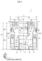
Fig. 2 is a plan view illustrating a cabin structure for a vessel according to Embodiment 2. -
Fig. 3 is a plan view illustrating a cabin structure for a vessel according to Embodiment 3. -
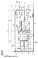
Fig. 4 is a plan view illustrating a cabin structure for a vessel according to Embodiment 4. -
Fig. 5 is a plan view illustrating a cabin structure for a vessel according toEmbodiment 5. -
Fig. 6 is a plan view illustrating a cabin structure for a vessel according toEmbodiment 6. - Hereinafter, embodiments according to the present invention will be described in detail with reference to the drawings. The present invention is not limited to the embodiments. In addition, configuration elements in the following embodiments include those which can be easily replaced by those skilled in the art, or those which are substantially identical.
-
Fig. 1 is a plan view illustrating a cabin structure for a vessel according toEmbodiment 1. The cabin structure for avessel 1 according to Embodiment 1 has been applied to vessels for carrying passengers, such as cargo ships, passenger ships, or research ships. Here, thevessel 1 hasmultiple cabins 5 arranged thereinside, and apassageway 6 is disposed adjacent to therespective cabins 5. - As illustrated in
Fig. 1 , thepassageway 6 furnished inside the vessel is furnished so as to extend along a longitudinal direction of thevessel 1. Themultiple cabins 5 are furnished between thepassageway 6 and anouter plate 7 of thevessel 1, and are arrayed side by side in the longitudinal direction of thevessel 1. According toEmbodiment 1, themultiple cabins 5 are furnished between thepassageway 6 and theouter plate 7. However, when thepassageway 6 is furnished side by side at multiple locations in a width direction of thevessel 1, themultiple cabins 5 may be furnished between thepassageway 6 and thepassageway 6. In addition, theouter plate 7 is configured to function as a strengthening member. - In the
multiple cabins 5 furnished inside the vessel, twoadjacent cabins cabin space 10. Thecabin space 10 has a rectangular shape in a plan view. In thecabin space 10 having the rectangular shape, four sides thereof are surrounded with a passageway-side wall 11 furnished on thepassageway 6 side, an outer plate-side wall (hull-side wall) 12 furnished on theouter plate 7 side, and a pair of sidewalls (two sidewalls) 13. In addition, thecabin space 10 internally includes apartition wall 14 which partitions thecabin space 10 into twocabins 5. - The passageway-
side wall 11 is furnished so as to extend in the longitudinal direction of thevessel 1, and has entrance/exit doors 21 respectively furnished in order to allow access to the twocabins 5. The outer plate-side wall 12 is furnished so as to extend in the longitudinal direction of thevessel 1. The outer plate-side wall 12 is furnished so as to face the passageway-side wall 11, and is furnished parallel to the passageway-side wall 11. The outer plate-side wall 12 has alighting window 22 through which external light is transmitted to thecabin space 10. Thelighting windows 22 are furnished at a predetermined interval in the longitudinal direction of thevessel 1. However, thelighting windows 22 are properly arranged without being furnished so as to necessarily correspond to themultiple cabins 5. - The pair of
sidewalls 13 are furnished so as to extend in the width direction of thevessel 1, and are arranged parallel to each other at a predetermined interval in the longitudinal direction of thevessel 1. Therespective sidewalls 13 are furnished so as to be orthogonal to the passageway-side wall 11 and the outer plate-side wall 12. An end portion on thepassageway 6 side is connected to the passageway-side wall 11, and an end portion on theouter plate 7 side is connected to the outer plate-side wall 12. - The
partition wall 14 is furnished between the passageway-side wall 11 and the outer plate-side wall 12. Thepartition wall 14 has atransverse partition wall 14a on thepassageway 6 side, atransverse partition wall 14b on theouter plate 7 side, and alongitudinal partition wall 14c which connects thetransverse partition wall 14a and thetransverse partition wall 14b to each other. - The
longitudinal partition wall 14c is furnished so as to extend in the longitudinal direction of thevessel 1, and is furnished parallel to the passageway-side wall 11 and the outer plate-side wall 12. The center of thelongitudinal partition wall 14c in the longitudinal direction of thevessel 1 is located at the center of a length L in the longitudinal direction between the pair ofsidewalls 13. Therefore, a length La in the longitudinal direction between the center of thelongitudinal partition wall 14c in the longitudinal direction and one (left side in the illustration) of thesidewalls 13 is the same as a length Lb in the longitudinal direction between the center of thelongitudinal partition wall 14c in the longitudinal direction and the other one (right side in the illustration) of thesidewalls 13. - In addition, the
longitudinal partition wall 14c is furnished at the center in the width direction of thevessel 1, which is a direction in which the passageway-side wall 11 and the outer plate-side wall 12 face each other. Therefore, thelongitudinal partition wall 14c equally partitions a length W in the width direction between an inner surface of the passageway-side wall 11 and an inner surface of the outer plate-side wall 12. In other words, a length Wb in the width direction between the inner surface of the passageway-side wall 11 and the center of thelongitudinal partition wall 14c is the same as a length Wa in the width direction between the inner surface of the outer plate-side wall 12 and the center of thelongitudinal partition wall 14c. - The
transverse partition wall 14a on thepassageway 6 side is furnished so as to extend in the width direction of thevessel 1, and is furnished parallel to the pair ofsidewalls 13. In thetransverse partition wall 14a, an end portion on thepassageway 6 side is connected to the passageway-side wall 11, and an end portion on theouter plate 7 side is connected to the other end portion (right side in the illustration) of thelongitudinal partition wall 14c. - The
transverse partition wall 14b on theouter plate 7 side is furnished so as to extend in the width direction of thevessel 1, and is furnished parallel to the pair ofsidewalls 13. In thetransverse partition wall 14b, an end portion on theouter plate 7 side is connected to the outer plate-side wall 12, and an end portion on thepassageway 6 side is connected to one end portion (left side in the illustration) of thelongitudinal partition wall 14c. - Then, in the
transverse partition wall 14a on thepassageway 6 side and thetransverse partition wall 14b on theouter plate 7 side, thelongitudinal partition wall 14c is furnished at the center in the width direction. Accordingly, respective lengths of thetransverse partition walls - The
cabin space 10 partitioned by thispartition wall 14 is arranged in a state where the twocabins cabins cabins cabins cabin 5a (left side in the illustration) is configured so that a larger area is formed on thepassageway 6 side and a smaller area is formed on theouter plate 7 side. In addition, between the twocabins other cabin 5b (right side in the illustration) is configured so that a smaller area is formed on thepassageway 6 side and a larger area is formed on theouter plate 7 side. - In each of the
cabins bunk beds 23, awash basin 24, awardrobe 25, an air-conditioning ventilation port 26, a table 27, chairs 28, and atelevision set 29 are properly arranged. - Specifically, in the
cabin 5a on the left side in the illustration, the twobunk beds 23 and thewash basin 24 are arranged in the larger area on thepassageway 6 side. The twobunk beds 23 are arranged close to thetransverse partition wall 14a, and are arranged so that the longitudinal direction thereof becomes the longitudinal direction of thevessel 1. Then, the twobunk beds 23 are arranged side by side at a predetermined interval in the width direction of thevessel 1. One of the twobunk beds 23 is arranged close to thelongitudinal partition wall 14c, and the other one of the twobunk beds 23 is arranged close to the passageway-side wall 11. Thewash basin 24 is arranged close to thesidewall 13 on the left side in the illustration. In addition, in thecabin 5a on the left side in the illustration, thewardrobe 25, the air-conditioning ventilation port 26, the table 27, thechairs 28, and thetelevision set 29 are arranged in the smaller area on theouter plate 7 side. Thewardrobe 25 is arranged close to thetransverse partition wall 14b, and is arranged on thepassageway 6 side. The air-conditioning ventilation port 26 is arranged close to thesidewall 13 on the left side in the illustration, and is arranged on theouter plate 7 side. The table 27 and thechairs 28 are arranged close to thetransverse partition wall 14b, and are arranged on theouter plate 7 side. Thetelevision set 29 is arranged above the air-conditioning ventilation port 26. - On the other hand, in the
cabin 5b on the right side in the illustration, the twobunk beds 23, the air-conditioning ventilation port 26, and thetelevision set 29 are arranged in the larger area on theouter plate 7 side. The twobunk beds 23 are arranged close to thetransverse partition wall 14b, and are arranged so that the longitudinal direction thereof becomes the longitudinal direction of thevessel 1. Then, the twobunk beds 23 are arranged side by side at a predetermined interval in the width direction of thevessel 1. One of the twobunk beds 23 is arranged close to thelongitudinal partition wall 14c, and the other one of the twobunk beds 23 is arranged close to the outer plate-side wall 12. The air-conditioning ventilation port 26 is arranged close to thesidewall 13 on the right side in the illustration, and is arranged on theouter plate 7 side. Thetelevision set 29 is arranged above the air-conditioning ventilation port 26. In addition, in thecabin 5b on the right side in the illustration, thewash basin 24, thewardrobe 25, the table 27, and thechairs 28 are arranged in the smaller area on thepassageway 6 side. Thewash basin 24 is arranged close to thesidewall 13 on the right side in the illustration. Thewardrobe 25 is arranged close to thetransverse partition wall 14a, and is arranged on thepassageway 6 side. The table 27 and thechairs 28 are arranged close to thetransverse partition wall 14a, and are arranged on theouter plate 7 side. - Here, in the
cabin space 10, a pillar (post member) 31 is furnished along thelongitudinal partition wall 14c of thepartition wall 14. Thepillar 31 is a columnar structural strengthening member which supports a load of an upper structure such as an upper deck. Thepillar 31 may be arranged at one or more locations. For example, thepillar 31 is properly arranged at the following arrangement positions. Thepillar 31 is properly arranged at an arrangement position P1 adjacent to one end portion (left side in the illustration) of thelongitudinal partition wall 14c in the longitudinal direction, at an arrangement position P2 adjacent to the other end portion (right side in the illustration) of thelongitudinal partition wall 14c in the longitudinal direction, at an arrangement position P3 adjacent to thepassageway 6 side of the center of thelongitudinal partition wall 14c in the longitudinal direction, and at an arrangement position P4 adjacent to theouter plate 7 side of the center of thelongitudinal partition wall 14c in the longitudinal direction. - As described above, according to
Embodiment 1, thelongitudinal partition wall 14c is furnished in the middle (at the center in the width direction) between the passageway-side wall 11 and the outer plate-side wall 12. Accordingly, when the post member such as thepillar 31 is furnished for thecabin space 10, thepillar 31 is arranged so as to extend along thelongitudinal partition wall 14c. In this manner, thepillar 31 can support thecabin space 10 so as to maintain an equal load balance in thecabin space 10 while ensuring comfort in thecabins cabin space 10 can be improved. In addition, since thepillar 31 is furnished, a structure body is favorably connected to upper and lower decks, thereby enabling vibrations to be suppressed. Furthermore, since thepillar 31 is furnished, strength requirements for decks or beams (aggregates) can be eased, and the weight of an upper structure in the vessel can be reduced. Accordingly, the hull weight can be reduced. In this case, if the weight of the upper structure is reduced, the center of gravity is lowered. Therefore, improved stability of the vessel can also be expected. The arrangement position for thepillar 31 is not particularly limited to the above-described arrangement positions P1 to P4 as long as thepillar 31 can be furnished so as to extend along thelongitudinal partition wall 14c. - According to
Embodiment 1, thepillar 31 is furnished as the post member. However, a configuration may be adopted in which thelongitudinal partition wall 14c functions as a structural strengthening wall by omitting thepillar 31. According to this configuration, thelongitudinal partition wall 14c itself can function as a structural strengthening member. Therefore, the structural strength of thecabin space 10 can be improved without impairing comfort in thecabins - In addition,
Embodiment 1 employs the bunk bed. However, a single stage-type bed may be employed without any particular limitation. - Next, a cabin structure for the
vessel 1 according to Embodiment 2 will be described with reference toFig. 2. Fig. 2 is a plan view illustrating the cabin structure of the vessel according to Embodiment 2. In Embodiment 2, in order to avoid repeated description compared toEmbodiment 1, only elements different from those inEmbodiment 1 will be described. The same reference numerals are given to configuration elements which are the same as those inEmbodiment 1. - In the
respective cabins cabin space 10 according to Embodiment 2, aprefabricated bath 35 and a night table 36 are furnished in addition to the household items furnished for therespective cabins Embodiment 1. Similarly toEmbodiment 1, in the twoadjacent cabins cabin space 10 is partitioned by thepartition wall 14 including thetransverse partition wall 14a on thepassageway 6 side, thetransverse partition wall 14b on theouter plate 7 side, and thelongitudinal partition wall 14c. Therefore, since thepartition wall 14 has the same configuration as that according toEmbodiment 1, description thereof will be omitted. - In the
respective cabins beds 23, thewash basin 24, thewardrobe 25, the air-conditioning ventilation port 26, the table 27, thechairs 28, thetelevision set 29, theprefabricated bath 35, and the night table 36 are properly arranged. - Specifically, in the
cabin 5a on the left side in the illustration, theprefabricated bath 35 is arranged in a smaller area on thepassageway 6 side. Theprefabricated bath 35 is arranged close to thesidewall 13 on the right side in the illustration, and is arranged so that the longitudinal direction thereof becomes the width direction of thevessel 1. In addition, in thecabin 5a on the left side in the illustration, the twobeds 23, thewash basin 24, thewardrobe 25, the air-conditioning ventilation port 26, the table 27, thechairs 28, thetelevision set 29, and the night table 36 are arranged in a larger area on theouter plate 7 side. The twobeds 23 are arranged close to thetransverse partition wall 14b, and are arranged so that the longitudinal direction thereof becomes the longitudinal direction of thevessel 1. Then, the twobeds 23 are arranged side by side at a predetermined interval in the width direction of thevessel 1. One of thebeds 23 is arranged close to the outer plate-side wall 12, and the other one of thebeds 23 is arranged on thepassageway 6 side by interposing the night table 36 between the twobeds 23. Thewash basin 24 is arranged close to thesidewall 13 on the left side in the illustration, and is arranged adjacent to theprefabricated bath 36. Thewardrobe 25 is arranged close to thesidewall 13 on the left side in the illustration, and is arranged close to the outer plate-side wall 12. The air-conditioning ventilation port 26 is arranged close to thesidewall 13 on the left side in the illustration, and is arranged adjacent to thewardrobe 25. The table 27 and thechairs 28 are arranged between thewardrobe 25 and one of thebeds 23. Thetelevision set 29 is arranged above the air-conditioning ventilation port 26. - On the other hand, in the
cabin 5b on the right side in the illustration, the twobeds 23, theprefabricated bath 35, and the night table 36 are arranged in a larger area on thepassageway 6 side. The twobeds 23 are arranged close to thetransverse partition wall 14a, and are arranged so that the longitudinal direction thereof becomes the longitudinal direction of thevessel 1. Then, the twobeds 23 are arranged side by side at a predetermined interval in the width direction of thevessel 1. One of thebeds 23 is arranged close to thelongitudinal partition wall 14c, and the other one of thebeds 23 is arranged on thepassageway 6 side by interposing the night table 36 between the twobeds 23. Theprefabricated bath 35 is arranged close to thesidewall 13 on the left side in the illustration, and is arranged so that the longitudinal direction thereof becomes the width direction of thevessel 1. In addition, in thecabin 5b on the right side in the illustration, thewash basin 24, thewardrobe 25, the air-conditioning ventilation port 26, the table 27, thechairs 28, and thetelevision set 29 are arranged in a smaller area on theouter plate 7 side. Thewash basin 24 is arranged close to thesidewall 13 on the right side in the illustration, and is arranged adjacent to theprefabricated bath 36. Thewardrobe 25 is arranged close to thesidewall 13 on the right side in the illustration, and is arranged close to theouter plate 7 side. The air-conditioning ventilation port 26 is arranged close to thesidewall 13 on the left side in the illustration, and is arranged adjacent to thewardrobe 25. The table 27 and thechairs 28 are arranged close to thetransverse partition wall 14b, and are arranged on theouter plate 7 side. Thetelevision set 29 is arranged above the air-conditioning ventilation port 26. - In addition, in the
cabin space 10, similarly toEmbodiment 1, thepillar 31 is furnished along thelongitudinal partition wall 14c of thepartition wall 14. Since the arrangement of thepillar 31 is the same as that according toEmbodiment 1, description thereof will be omitted. - As described above, according to Embodiment 2, even when the
prefabricated bath 35 is furnished, thelongitudinal partition wall 14c can be furnished in the middle (at the center in the width direction) between the passageway-side wall 11 and the outer plate-side wall 12. Therefore, similar toEmbodiment 1, when a post member such as thepillar 31 is furnished for thecabin space 10, thepillar 31 is arranged along thelongitudinal partition wall 14c. In this manner, thepillar 31 can support thecabin space 10 so as to maintain an equal load balance in thecabin space 10 while ensuring comfort in thecabins cabin space 10 can be improved. - Next, a cabin structure for the
vessel 1 according to Embodiment 3 will be described with reference toFig. 3. Fig. 3 is a plan view illustrating the cabin structure of the vessel according to Embodiment 3. In Embodiment 3, in order to avoid repeated description compared to Embodiment 2, only elements different from those in Embodiment 2 will be described. The same reference numerals are given to configuration elements which are the same as those in Embodiment 2. - In the
cabin space 10 according to Embodiment 3, a slidingdoor 41 is furnished on thelongitudinal partition wall 14c of thepartition wall 14 according to Embodiment 2. The slidingdoor 41 functions as a door which allows access to the twocabins cabin space 10. When the slidingdoor 41 is furnished on thelongitudinal partition wall 14c, it is preferable to arrange the twobeds 23 arranged in thecabin 5b on the right side in the illustration so as to be close to the passageway-side wall 11. - As described above, according to Embodiment 3, since the sliding
door 41 is furnished, the twocabins cabin space 10. - Next, a cabin structure for the
vessel 1 according to Embodiment 4 will be described with reference toFig. 4. Fig. 4 is a plan view illustrating the cabin structure of the vessel according to Embodiment 4. In Embodiment 4, in order to avoid repeated description compared toEmbodiments 1 to 3, only elements different from those inEmbodiments 1 to 3 will be described. The same reference numerals are given to configuration elements which are the same as those inEmbodiments 1 to 3. - According to Embodiment 4, the two
adjacent cabins cabin space 10 are partitioned by apartition wall 51. In addition, the twoprefabricated baths 35 furnished for therespective cabins prefabricated bath module 52. - The
prefabricated bath module 52 is arranged close to the passageway-side wall 11, and is arranged at the center in the longitudinal direction of thevessel 1. - The
partition wall 51 which partitions thecabin space 10 is furnished between theprefabricated bath module 52 and the outer plate-side wall 12. Thepartition wall 51 has atransverse partition wall 51a on theprefabricated bath module 52 side, atransverse partition wall 51b on theouter plate 7 side, atransverse partition wall 51c between thetransverse partition wall 51a and thetransverse partition wall 51b, alongitudinal partition wall 51d which connects thetransverse partition wall 51a and thetransverse partition wall 51c to each other, and alongitudinal partition wall 51e which connects thetransverse partition wall 51b and thetransverse partition wall 51c to each other. - Similarly to the
longitudinal partition wall 14c according toEmbodiment 1, thelongitudinal partition wall 51d is furnished so as to extend in the longitudinal direction of thevessel 1, and is furnished parallel to the passageway-side wall 11 and the outer plate-side wall 12. In thelongitudinal partition wall 51d, the center in the longitudinal direction of thevessel 1 is located at the center of a length L in the longitudinal direction between the pair ofsidewalls 13. Therefore, a length La in the longitudinal direction between the center of thelongitudinal partition wall 51d in the longitudinal direction and one (left side in the illustration) of thesidewalls 13 is the same as a length Lb in the longitudinal direction between the center of thelongitudinal partition wall 51d in the longitudinal direction and the other one (right side in the illustration) of thesidewalls 13. - In addition, the
longitudinal partition wall 51d is furnished at the center in the width direction of thevessel 1, which is a direction in which the passageway-side wall 11 and the outer plate-side wall 12 face each other. Therefore, thelongitudinal partition wall 51d equally partitions a length W in the width direction between an inner surface of the passageway-side wall 11 and an inner surface of the outer plate-side wall 12. In other words, a length Wb in the width direction between the inner surface of the passageway-side wall 11 and the center of thelongitudinal partition wall 51d is the same as a length Wa in the width direction between the inner surface of the outer plate-side wall 12 and the center of thelongitudinal partition wall 51d. - The
transverse partition wall 51a on thepassageway 6 side is furnished so as to extend in the width direction of thevessel 1, and is furnished parallel to the pair ofsidewalls 13. In thetransverse partition wall 51a, an end portion on thepassageway 6 side is connected to theprefabricated bath module 52, and an end portion on theouter plate 7 side is connected to the other end portion (right side in the illustration) of thelongitudinal partition wall 51d. - The
transverse partition wall 51b on theouter plate 7 side is furnished so as to extend in the width direction of thevessel 1, and is furnished parallel to the pair ofsidewalls 13. Thetransverse partition wall 51b is arranged at the center in the longitudinal direction of thevessel 1. In thetransverse partition wall 51b, an end portion on theouter plate 7 side is connected to the outer plate-side wall 12, and an end portion on thepassageway 6 side is connected to the other end portion (right side in the illustration) of thelongitudinal partition wall 51e. - The
transverse partition wall 51c which connects thetransverse partition wall 51a and thetransverse partition wall 51b to each other is furnished so as to extend in the width direction of thevessel 1, and is furnished parallel to the pair ofsidewalls 13. In thetransverse partition wall 51c, an end portion on thepassageway 6 side is connected to one end portion (left side in the illustration) of thelongitudinal partition wall 51d, and an end portion onouter plate 7 side is connected to one end portion (left side in the illustration) of thelongitudinal partition wall 51e. - The
longitudinal partition wall 51e which connects thetransverse partition wall 51b and thetransverse partition wall 51c to each other is furnished so as to extend in the longitudinal direction of thevessel 1, and is furnished parallel to the passageway-side wall 11 and the outer plate-side wall 12. In thelongitudinal partition wall 51e, one end portion (left side in the illustration) is connected to an end portion on theouter plate 7 side of thetransverse partition wall 51c, and the other end portion (right side in the illustration) is connected to an end portion on thepassageway 6 side of thetransverse partition wall 51b. - In the
cabin space 10 partitioned by thispartition wall 51, the twocabins cabins respective cabins prefabricated bath 35 configured to include the above-describedprefabricated bath module 52 is arranged in addition to the household items such as the twobunk beds 23, thewash basin 24, thewardrobe 25, the air-conditioning ventilation port 26, the table 27, thechairs 28, and thetelevision set 29. - In addition, in the
cabin space 10, similarly toEmbodiment 1, thepillar 31 is furnished along thelongitudinal partition wall 51d of thepartition wall 51. Since the arrangement of thepillar 31 is the same as that according toEmbodiment 1, description thereof will be omitted. - As described above, according to Embodiment 4, even when the
prefabricated bath module 52 is furnished, thelongitudinal partition wall 14c can be furnished in the middle (at the center in the width direction) between the passageway-side wall 11 and the outer plate-side wall 12. Therefore, similar toEmbodiment 1, when a post member such as thepillar 31 is furnished for thecabin space 10, thepillar 31 is arranged along thelongitudinal partition wall 14c. In this manner, thepillar 31 can support thecabin space 10 so as to maintain an equal load balance in thecabin space 10 while ensuring comfort in thecabins cabin space 10 can be improved. - In addition, according to Embodiment 4, the two
prefabricated baths 35 can be configured to include thesingle module 52. Therefore, costs required for theprefabricated bath 35 can be suppressed. In addition, it is possible to simplify installation work for theprefabricated bath 35. - Next, a cabin structure for the
vessel 1 according toEmbodiment 5 will be described with reference toFig. 5. Fig. 5 is a plan view illustrating the cabin structure of the vessel according toEmbodiment 5. InEmbodiment 5, in order to avoid repeated description compared toEmbodiments 1 to 4, only elements different from those inEmbodiments 1 to 4 will be described. The same reference numerals are given to configuration elements which are the same as those inEmbodiments 1 to 4. - According to
Embodiment 5, averanda 61 is furnished outside on theouter plate 7 side of thecabin space 10. That is, thecabin space 10 and theveranda 61 are differently partitioned. Theveranda 61 is partitioned into twoverandas cabins veranda partition wall 62. Theveranda partition wall 62 is furnished so as to extend in the width direction of thevessel 1. Theveranda partition wall 62 is located at the center of a length L in the longitudinal direction between the pair ofsidewalls 13. - Similarly to Embodiment 2, the two
adjacent cabins cabin space 10 are partitioned by thepartition wall 14 including thetransverse partition wall 14a on thepassageway 6 side, thetransverse partition wall 14b on theouter plate 7 side, and thelongitudinal partition wall 14c. Therefore, since thepartition wall 14 has the same configuration as that according to Embodiment 2, description thereof will be omitted. - The two
cabins respective cabins beds 23, thewardrobe 25, the air-conditioning ventilation port 26, the table 27, the chairs (sofas) 28, thetelevision set 29, and theprefabricated bath 35 are arranged. - In addition, in the
cabin space 10, similarly toEmbodiment 1, thepillar 31 is furnished along thelongitudinal partition wall 14c of thepartition wall 14. Since the arrangement of thepillar 31 is the same as that according toEmbodiment 1, description thereof will be omitted. - As described above, according to
Embodiment 5, even when theveranda 61 is furnished outside thecabin space 10, thelongitudinal partition wall 14c can be furnished in the middle (at the center in the width direction) between the passageway-side wall 11 and the outer plate-side wall 12. Therefore, similar toEmbodiment 1, when a post member such as thepillar 31 is furnished for thecabin space 10, thepillar 31 is arranged along thelongitudinal partition wall 14c. In this manner, thepillar 31 can support thecabin space 10 so as to maintain an equal load balance in thecabin space 10 while ensuring comfort in thecabins cabin space 10 can be improved. - Next, a cabin structure for the
vessel 1 according toEmbodiment 6 will be described with reference toFig. 6. Fig. 6 is a plan view illustrating the cabin structure of the vessel according toEmbodiment 6. InEmbodiment 6, in order to avoid repeated description compared toEmbodiments 1 to 5, only elements different from those inEmbodiments 1 to 5 will be described. The same reference numerals are given to configuration elements which are the same as those inEmbodiments 1 to 5. - According to
Embodiment 6, theveranda 61 is furnished inside on theouter plate 7 side of thecabin space 10. That is, theveranda 61 is furnished inside thecabin space 10. Theveranda 61 is partitioned into twoverandas cabins veranda partition wall 62. In addition, the twocabins verandas exterior partition wall 63. - The
veranda partition wall 62 is furnished so as to extend in the width direction of thevessel 1. Theveranda partition wall 62 is located at the center in a length L in the longitudinal direction between the pair ofsidewalls 13. The interior/exterior partition wall 63 is furnished so as to extend in the longitudinal direction of thevessel 1, and both ends thereof are respectively connected to the pair ofsidewalls 13. - In addition, the two
prefabricated baths 35 furnished for therespective cabins prefabricated bath module 52. Theprefabricated bath module 52 is arranged close to the passageway-side wall 11, and is arranged at the center in the longitudinal direction of thevessel 1. - Similarly to
Embodiment 1, thecabin space 10 has a rectangular shape in a plan view. Four sides of thecabin space 10 are surrounded with the passageway-side wall 11 furnished on thepassageway 6 side, the outer plate-side wall (hull-side wall) 12 furnished on theouter plate 7 side, and the pair of sidewalls (two sidewalls) 13. In this case, an external opening (not illustrated) through which the outside of the vessel and theveranda 61 communicate with each other is formed on the outer plate-side wall 12. - A partition wall 71 which partitions the
cabin space 10 is furnished between theprefabricated bath module 52 and the outer plate-side wall 12. The partition wall 71 has atransverse partition wall 71a on theprefabricated bath module 52 side, theveranda partition wall 62 on theouter plate 7 side, atransverse partition wall 71c between thetransverse partition wall 71a and theveranda partition wall 62, thelongitudinal partition wall 51d which connects thetransverse partition wall 51a and thetransverse partition wall 51c to each other, and the interior/exterior partition wall 63 which connects theveranda partition wall 62 and thetransverse partition wall 51c to each other. - The
longitudinal partition wall 71d is the same as thelongitudinal partition wall 51d according to Embodiment 4, thetransverse partition wall 71a on thepassageway 6 side is the same as thetransverse partition wall 51a according to Embodiment 4, and thetransverse partition wall 71c is the same as thetransverse partition wall 51c according to Embodiment 4. Accordingly, description thereof will be omitted. - In addition, the
veranda partition wall 62 is the same as thetransverse partition wall 51b according to Embodiment 4. An end portion thereof on theouter plate 7 side is connected to the outer plate-side wall 12, and an end portion thereof on thepassageway 6 side is connected to the interior/exterior partition wall 63. Furthermore, the interior/exterior partition wall 63 is substantially the same as thelongitudinal partition wall 51e according to Embodiment 4. One end portion (left side in the illustration) is connected to one of thesidewalls 13, and the other end portion (right side in the illustration) is connected to the other one of thesidewalls 13. - The two
cabins Embodiment 5, in therespective cabins beds 23, thewardrobe 25, the air-conditioning ventilation port 26, the table 27, the chairs (sofas) 28, thetelevision set 29, and theprefabricated bath 35 are arranged. - In addition, in the
cabin space 10, similarly toEmbodiment 1, thepillar 31 is furnished along thelongitudinal partition wall 71d of the partition wall 71. Since the arrangement of thepillar 31 is the same as that according toEmbodiment 1, description thereof will be omitted. - As described above, according to
Embodiment 6, even when theveranda 61 is furnished inside thecabin space 10, thelongitudinal partition wall 71d can be furnished in the middle (at the center in the width direction) between the passageway-side wall 11 and the outer plate-side wall 12. Therefore, similar toEmbodiment 1, when a post member such as thepillar 31 is furnished for thecabin space 10, thepillar 31 is arranged along thelongitudinal partition wall 71d. In this manner, thepillar 31 can support thecabin space 10 so as to maintain an equal load balance in thecabin space 10 while ensuring comfort in thecabins cabin space 10 can be improved. - Embodiments 2 to 6 employ the
prefabricated bath 35, but may employ a shower bathing unit without any particular limitation. -
- 1
- VESSEL
- 5
- CABIN
- 6
- PASSAGEWAY
- 7
- OUTER PLATE
- 10
- CABIN SPACE
- 11
- PASSAGEWAY-SIDE WALL
- 12
- OUTER PLATE-SIDE WALL (HULL-SIDE WALL)
- 13
- SIDEWALL
- 14
- PARTITION WALL
- 14a
- TRANSVERSE PARTITION WALL
- 14b
- TRANSVERSE PARTITION WALL
- 14c
- LONGITUDINAL PARTITION WALL
- 31
- PILLAR
- 35
- PREFABRICATED BATH
- 36
- NIGHT TABLE
- 41
- SLIDING DOOR
- 51
- PARTITION WALL
- 51a
- TRANSVERSE PARTITION WALL
- 51b
- TRANSVERSE PARTITION WALL
- 51c
- TRANSVERSE PARTITION WALL
- 51d
- LONGITUDINAL PARTITION WALL
- 51e
- LONGITUDINAL PARTITION WALL
- 52
- PREFABRICATED BATH MODULE
- 61
- VERANDA
- 62
- VERANDA PARTITION WALL
- 63
- INTERIOR/EXTERIOR PARTITION WALL
- 71
- PARTITION WALL
- 71a
- TRANSVERSE PARTITION WALL
- 71c
- TRANSVERSE PARTITION WALL
- 71d
- LONGITUDINAL PARTITION WALL
Claims (4)
- A cabin structure for a vessel which includes a cabin space having two adjacent cabins,
wherein the cabin space includes:a passageway-side wall that faces a passageway inside the vessel;a hull-side wall that faces the passageway-side wall by being furnished in parallel thereto;two sidewalls that are respectively furnished toward a stern side and a bow side of the vessel;a longitudinal partition wall that is furnished at a central location so as to extend parallel between the passageway-side wall and the hull-side wall; andtransverse partition walls that are respectively furnished between the longitudinal partition wall and the passageway-side wall, and between the longitudinal partition wall and the hull-side wall, andwherein the longitudinal partition wall is a structural strengthening wall. - A cabin structure for a vessel which includes a cabin space having two adjacent cabins,
wherein the cabin space includes:a passageway-side wall that faces a passageway inside the vessel;a hull-side wall that faces the passageway-side wall by being furnished in parallel thereto;two sidewalls that are respectively furnished toward a stern side and a bow side of the vessel;a longitudinal partition wall that is furnished at a central location so as to extend parallel between the passageway-side wall and the hull-side wall;transverse partition walls that are respectively furnished between the longitudinal partition wall and the passageway-side wall, and between the longitudinal partition wall and the hull-side wall; anda post member that is furnished along the longitudinal partition wall, andwherein the post member is a structural strengthening wall. - The cabin structure for a vessel according to Claim 1 or 2,
wherein the cabin space further includes a sliding door that is furnished on the longitudinal partition wall in order to allow access to the two cabins. - The cabin structure for a vessel according to any one of Claims 1 to 3,
wherein the cabin space further includes two prefabricated baths that are respectively furnished for the two cabins, and
wherein the two prefabricated baths are furnished adjacent to each other, and are configured to include a single module.
Applications Claiming Priority (2)
| Application Number | Priority Date | Filing Date | Title |
|---|---|---|---|
| JP2013135540A JP2015009638A (en) | 2013-06-27 | 2013-06-27 | Habitable room structure of vessel |
| PCT/JP2014/064877 WO2014208301A1 (en) | 2013-06-27 | 2014-06-04 | Cabin structure for vessel |
Publications (2)
| Publication Number | Publication Date |
|---|---|
| EP2987717A1 true EP2987717A1 (en) | 2016-02-24 |
| EP2987717A4 EP2987717A4 (en) | 2016-04-20 |
Family
ID=52141649
Family Applications (1)
| Application Number | Title | Priority Date | Filing Date |
|---|---|---|---|
| EP14816739.8A Withdrawn EP2987717A4 (en) | 2013-06-27 | 2014-06-04 | Cabin structure for vessel |
Country Status (4)
| Country | Link |
|---|---|
| EP (1) | EP2987717A4 (en) |
| JP (1) | JP2015009638A (en) |
| KR (1) | KR20160003832A (en) |
| WO (1) | WO2014208301A1 (en) |
Cited By (2)
| Publication number | Priority date | Publication date | Assignee | Title |
|---|---|---|---|---|
| EP3345822A1 (en) * | 2017-01-10 | 2018-07-11 | Focus Yacht Design GmbH | Cabin arrangement for a passenger ship |
| WO2019089320A1 (en) * | 2017-10-31 | 2019-05-09 | Virgin Cruises Intermediate Limited | Double-cabin featuring an angular wall |
Families Citing this family (3)
| Publication number | Priority date | Publication date | Assignee | Title |
|---|---|---|---|---|
| JP6257048B2 (en) * | 2015-02-03 | 2018-01-10 | 三菱重工業株式会社 | Ship room structure and ship |
| CN114394197B (en) * | 2022-01-29 | 2024-05-24 | 招商局工业科技(上海)有限公司 | Regional structure is built on boats and ships |
| CN116395118A (en) * | 2023-04-12 | 2023-07-07 | 广船国际有限公司 | A kind of layout method of ship chimney structure and ship |
Family Cites Families (6)
| Publication number | Priority date | Publication date | Assignee | Title |
|---|---|---|---|---|
| DE2352444C3 (en) * | 1973-10-19 | 1978-09-14 | Adolf 2000 Hamburg Berg | Double-shell fire-retardant partition, especially for the interior construction of ships |
| JPS5283418U (en) * | 1975-12-18 | 1977-06-22 | ||
| FI78036C (en) * | 1987-05-27 | 1989-06-12 | Waertsilae Meriteollisuus | ANORDNING FOER HYTTELEMENT. |
| FR2834687A1 (en) * | 2002-01-11 | 2003-07-18 | Denis Laming | Cruise ship with improved structure houses rows of cabins on several decks and has hull extended upwards along two overhanging sides with V-shaped section housing part of cabin rows and leaving widely open central space |
| ITPD20060037A1 (en) * | 2006-02-03 | 2007-08-04 | Ct Per Gli Studi Di Tecnica Navale Spa | PASSENGER SHIP IN PARTICULAR FROM CRUISE AND ASSEMBLY CABINS FOR PASSENGER SHIP |
| JP2010095114A (en) * | 2008-10-15 | 2010-04-30 | Daiko Sangyo:Kk | Compartment module for marine vessels |
-
2013
- 2013-06-27 JP JP2013135540A patent/JP2015009638A/en active Pending
-
2014
- 2014-06-04 EP EP14816739.8A patent/EP2987717A4/en not_active Withdrawn
- 2014-06-04 KR KR1020157034127A patent/KR20160003832A/en not_active Ceased
- 2014-06-04 WO PCT/JP2014/064877 patent/WO2014208301A1/en not_active Ceased
Cited By (4)
| Publication number | Priority date | Publication date | Assignee | Title |
|---|---|---|---|---|
| EP3345822A1 (en) * | 2017-01-10 | 2018-07-11 | Focus Yacht Design GmbH | Cabin arrangement for a passenger ship |
| WO2019089320A1 (en) * | 2017-10-31 | 2019-05-09 | Virgin Cruises Intermediate Limited | Double-cabin featuring an angular wall |
| CN111448357A (en) * | 2017-10-31 | 2020-07-24 | 维京巡航中间有限公司 | Double Stateroom with Angled Dividing Wall |
| US11674301B2 (en) | 2017-10-31 | 2023-06-13 | Virgin Cruises Intermediate Limited | Double-cabin featuring an angular wall |
Also Published As
| Publication number | Publication date |
|---|---|
| WO2014208301A1 (en) | 2014-12-31 |
| EP2987717A4 (en) | 2016-04-20 |
| JP2015009638A (en) | 2015-01-19 |
| KR20160003832A (en) | 2016-01-11 |
Similar Documents
| Publication | Publication Date | Title |
|---|---|---|
| US20180334254A1 (en) | Aircraft comprising a luggage storage container housed in the leading edge concavity | |
| RU2449920C2 (en) | Aircraft tail cone | |
| KR101372982B1 (en) | Marine partition module | |
| EP2398693B1 (en) | Single hull cruise vessel | |
| WO2014208301A1 (en) | Cabin structure for vessel | |
| JP5323918B2 (en) | Cabin assembly components for cruise ships | |
| US20050178904A1 (en) | Modular overhead privacy system | |
| KR970001353B1 (en) | Method of installing an upper structural layer on a ship and passenger ship having such upper structural layer | |
| WO2017033372A1 (en) | Automobile carrying vessel | |
| US9051051B1 (en) | Floating aircraft archway and method therefor | |
| ES2922638T3 (en) | Cabin for an elevator in an elevator shaft | |
| AU2003216941B2 (en) | System and method in water-craft or other structure | |
| KR20140046779A (en) | Arrangement structure of deckhouse on ship | |
| KR20150013574A (en) | Cabin for a floating installation with lines which contribute to reinforcement | |
| JP2014084080A (en) | Habitable room structure of ship | |
| FI121992B (en) | Process and building system for the manufacture of a floating structure | |
| CN110662699A (en) | Aircraft cabin comprising a cargo area intended to accommodate passengers | |
| KR20080066053A (en) | Arrangement of receiving spaces located inside the vehicle | |
| US11459107B2 (en) | Aircraft having a specific arranging module | |
| KR101201353B1 (en) | The Bridge Wing Support of a Ship | |
| US20250249987A1 (en) | Modular ship cabins | |
| WO2015167344A1 (en) | Room separation device | |
| FI74244C (en) | Fartyg. | |
| JPS63173786A (en) | Guest room layout structure and its production method | |
| US10899370B2 (en) | Paneling modules for vehicles |
Legal Events
| Date | Code | Title | Description |
|---|---|---|---|
| PUAI | Public reference made under article 153(3) epc to a published international application that has entered the european phase |
Free format text: ORIGINAL CODE: 0009012 |
|
| 17P | Request for examination filed |
Effective date: 20151119 |
|
| AK | Designated contracting states |
Kind code of ref document: A1 Designated state(s): AL AT BE BG CH CY CZ DE DK EE ES FI FR GB GR HR HU IE IS IT LI LT LU LV MC MK MT NL NO PL PT RO RS SE SI SK SM TR |
|
| AX | Request for extension of the european patent |
Extension state: BA ME |
|
| A4 | Supplementary search report drawn up and despatched |
Effective date: 20160317 |
|
| RIC1 | Information provided on ipc code assigned before grant |
Ipc: B63B 19/00 20060101ALI20160311BHEP Ipc: B63B 29/04 20060101ALI20160311BHEP Ipc: B63B 29/02 20060101AFI20160311BHEP Ipc: B63B 11/02 20060101ALI20160311BHEP |
|
| DAX | Request for extension of the european patent (deleted) | ||
| 17Q | First examination report despatched |
Effective date: 20161213 |
|
| STAA | Information on the status of an ep patent application or granted ep patent |
Free format text: STATUS: THE APPLICATION IS DEEMED TO BE WITHDRAWN |
|
| 18D | Application deemed to be withdrawn |
Effective date: 20170425 |