EP2987700A1 - Steering device - Google Patents
Steering device Download PDFInfo
- Publication number
- EP2987700A1 EP2987700A1 EP15181354.0A EP15181354A EP2987700A1 EP 2987700 A1 EP2987700 A1 EP 2987700A1 EP 15181354 A EP15181354 A EP 15181354A EP 2987700 A1 EP2987700 A1 EP 2987700A1
- Authority
- EP
- European Patent Office
- Prior art keywords
- steering
- rotation
- shaft
- opening
- inner tube
- Prior art date
- Legal status (The legal status is an assumption and is not a legal conclusion. Google has not performed a legal analysis and makes no representation as to the accuracy of the status listed.)
- Granted
Links
Images



Classifications
-
- B—PERFORMING OPERATIONS; TRANSPORTING
- B62—LAND VEHICLES FOR TRAVELLING OTHERWISE THAN ON RAILS
- B62D—MOTOR VEHICLES; TRAILERS
- B62D1/00—Steering controls, i.e. means for initiating a change of direction of the vehicle
- B62D1/02—Steering controls, i.e. means for initiating a change of direction of the vehicle vehicle-mounted
- B62D1/16—Steering columns
- B62D1/18—Steering columns yieldable or adjustable, e.g. tiltable
- B62D1/19—Steering columns yieldable or adjustable, e.g. tiltable incorporating energy-absorbing arrangements, e.g. by being yieldable or collapsible
- B62D1/192—Yieldable or collapsible columns
-
- B—PERFORMING OPERATIONS; TRANSPORTING
- B60—VEHICLES IN GENERAL
- B60R—VEHICLES, VEHICLE FITTINGS, OR VEHICLE PARTS, NOT OTHERWISE PROVIDED FOR
- B60R25/00—Fittings or systems for preventing or indicating unauthorised use or theft of vehicles
- B60R25/01—Fittings or systems for preventing or indicating unauthorised use or theft of vehicles operating on vehicle systems or fittings, e.g. on doors, seats or windscreens
- B60R25/02—Fittings or systems for preventing or indicating unauthorised use or theft of vehicles operating on vehicle systems or fittings, e.g. on doors, seats or windscreens operating on the steering mechanism
-
- B—PERFORMING OPERATIONS; TRANSPORTING
- B62—LAND VEHICLES FOR TRAVELLING OTHERWISE THAN ON RAILS
- B62D—MOTOR VEHICLES; TRAILERS
- B62D1/00—Steering controls, i.e. means for initiating a change of direction of the vehicle
- B62D1/02—Steering controls, i.e. means for initiating a change of direction of the vehicle vehicle-mounted
- B62D1/16—Steering columns
- B62D1/18—Steering columns yieldable or adjustable, e.g. tiltable
- B62D1/184—Mechanisms for locking columns at selected positions
Definitions
- the present invention relates to a steering device.
- a steering device including a column having an outer column and an inner column. See Japanese Patent Application Publication No. 2012-162152 ( JP 2012-162152 A ).
- the inner column is relatively movable with respect to the outer column.
- the inner column is disposed on the upper side with respect to the outer column.
- the steering device is configured to lock the inner column so that the inner column does not move with respect to the outer column by reducing the diameter of a holding body portion of the outer column by tightening a pair of tightening pieces of the outer column by use of a tightener including a bolt shaft.
- a keylock device is attached to the inner column on the upper side.
- the keylock device is a device that restricts rotation of a steering member when an ignition key is extracted.
- the keylock device includes a protruding portion that advances toward and retracts from the center axis of the steering shaft in response to extraction and insertion of the ignition key.
- a protruding portion that advances toward and retracts from the center axis of the steering shaft in response to extraction and insertion of the ignition key.
- a steering device includes: a steering member; a steering shaft, to one end of which the steering member is coupled; a steering column including an outer tube and an inner tube that are fitted so as to be relatively slidable with respect to each other, the steering column supporting the steering shaft and being contractable upon a secondary collision; and a rotation restriction mechanism that restricts rotation of the inner tube.
- the outer tube includes a first opening.
- the inner tube includes a second opening.
- the second opening includes: a pair of rotation restricted edge portions that face each other in a circumferential direction; and a driving edge portion that crosses the pair of rotation restricted edge portions.
- the rotation restriction mechanism includes: a support shaft, a position of which with respect to the outer tube is not varied upon the secondary collision; a restriction member supported on an outer periphery of the support shaft so as to be relatively rotatable, the restriction member being displaceable between an inserted position at which the restriction member is inserted into the second opening through the first opening and a retracted position at which the restriction member is retracted from the second opening; and an urging member that urges the restriction member toward the inserted position.
- the restriction member includes: a rotation restricting portion that engages with a corresponding one of the rotation restricted edge portions at the inserted position to restrict relative rotation between the tubes; and a driven portion that engages with the driving edge portion upon the secondary collision.
- the driving edge portion is configured to drive the restriction member toward the retracted position via the driven portion upon the secondary collision.
- the rotation restricting portion of the restriction member engages with the rotation restricted edge portion of the second opening when the restriction member which is urged by the urging member is at the inserted position at which the restriction member is inserted into the second opening of the inner tube through the first opening of the outer tube.
- the driving edge portion of the second opening drives the restriction member to the retracted position at which the restriction member is retracted from the second opening.
- the rotation restriction mechanism does not adversely affect contraction of the steering column upon a secondary collision.
- the outer tube may be a lower tube supported by a vehicle body; the inner tube may be an upper tube; and the support shaft may be supported by the vehicle body.
- the upper tube that serves as the inner tube can move with respect to the lower tube that serves as the outer tube supported by the vehicle body and the support shaft upon a secondary collision.
- the steering device may further include a lock device.
- the lock device may include: a first side plate including a long tilt groove and supported on the vehicle body; a second side plate including an insertion groove and fixed to the outer tube; a tightening shaft that serves as the support shaft inserted through the long tilt groove and the insertion groove; and an operation lever that rotates together with the tightening shaft.
- the lock device may be configured to fix the steering member in position by tightening the first side plate to the second side plate by operating the operation lever after the steering member is adjusted to a desired inclined position with respect to the vehicle body.
- the tightening shaft included in the lock device which fixes the steering member in position after the steering member is adjusted to a desired inclined position with respect to the vehicle body also serves as the support shaft which supports the restriction member, it is possible to simplify the structure.
- the driven portion may be a cam surface inclined with respect to an axial direction of the inner tube.
- the driving edge portion of the second opening of the inner tube which moves in the axial direction drives the restriction member to the retracted position upon a secondary collision via the cam surface as the driven portion which is inclined with respect to the axial direction.
- the second opening may include an extraction restricted edge portion that faces the driving edge portion; and the restriction member may include an extraction restricting portion that engages with the extraction restricted edge portion to restrict extraction of the inner tube from the outer tube.
- the extraction restricting portion of the restriction member engages with the extraction restricted edge portion of the second opening during normal times or after a secondary collision, which restricts extraction of the inner tube from the outer tube.
- FIG. 1 is a schematic sectional view illustrating a schematic configuration of a steering device according to an embodiment of the present invention.
- a steering device 1 includes a steering member 2 such as a steering wheel, a steering shaft 3, to one end of which in an axial direction X the steering member 2 is coupled, and a steering mechanism 5 coupled to the steering shaft 3 via an intermediate shaft 4 etc.
- the steering mechanism 5 is a rack-and-pinion mechanism, for example, that steers steered wheels (not illustrated) in conjunction with a steering operation of the steering member 2. Rotation of the steering member 2 is transferred to the steering mechanism 5 via the steering shaft 3, the intermediate shaft 4, etc. Rotation transferred to the steering mechanism 5 is converted into axial movement of a rack shaft (not illustrated). Consequently, the steered wheels are steered.
- the steering shaft 3 includes a tubular upper shaft 6 and a lower shaft 7 that are fitted so as to be relatively slidable through spline fitting or serration fitting, for example.
- the steering member 2 is coupled to one end of the upper shaft 6.
- the steering shaft 3 is expandable in the axial direction X.
- the steering device 1 includes a hollow steering column 8 that rotatably supports the steering shaft 3.
- the steering shaft 3 is inserted through the steering column 8, and supported by the steering column 8 so as to be rotatable via a plurality of bearings 9 and 10.
- the steering column 8 includes an inner tube 11, which is an upper tube, and an outer tube 12, which is a lower tube, fitted so as to be relatively slidable.
- the steering column 8 is expandable in the axial direction X.
- the inner tube 11 supports the upper shaft 6 so as to be rotatable via the bearing 9.
- the inner tube 11 is coupled to the upper shaft 6 so as to be movable in accompaniment in the axial direction X of the steering shaft 3 via the bearing 9.
- the steering device 1 includes a fixed bracket 14 fixed to a vehicle body 13, a tilt center shaft 15 supported by the fixed bracket 14, and a column bracket 16 fixed to the outer periphery of the outer tube 12 and rotatably supported by the tilt center shaft 15.
- the steering column 8 and the steering shaft 3 are tiltable in a tilt direction Y about a tilt center CC which is the center axis of the tilt center shaft 15.
- the steering device 1 is configured as a steering device having a tilt adjustment mechanism that adjusts the inclined position of the steering member 2 in the tilt direction Y by tilting the steering shaft 3 and the steering column 8 about the tilt center CC.
- the steering device 1 does not have a telescopic adjustment function of adjusting the axial position of the steering member 2 by moving or expanding and contracting the steering shaft 3 and the steering column 8 in the axial direction X.
- the steering device 1 has a function of absorbing a shock by contracting the steering column 8 in the axial direction X together with the steering shaft 3 upon a secondary collision.
- the steering device 1 includes a first bracket 17 fixed to the vehicle body 13, a second bracket 18 (corresponding to a distance bracket) fixed to the inner tube 11 of the steering column 8, and a lock device 19.
- the lock device 19 locks the relative positions of the brackets 17 and 18, which fixes the steering column 8 in position with respect to the vehicle body 13 to fix the steering member 2 in position.
- the first bracket 17 includes a pair of first side plates 20 (only one of the first side plates 20 is illustrated in FIG. 1 ) to be tightened.
- a long tilt groove 21 that extends in the tilt direction Y to serve as a first insertion groove is formed in each of the first side plates 20.
- the second bracket 18 includes a pair of second side plates 22 (only one of the second side plates 22 is illustrated in FIG. 1 ) to be tightened.
- a second insertion groove 23 (see FIG. 2 ) is formed in each of the second side plates 22.
- the lock device 19 includes the first side plates 20 and the second side plates 22 to be tightened, a tightening shaft 24 inserted through the long tilt grooves 21 (first insertion grooves) of the first side plates 20 and the second insertion grooves 23 of the second side plates 22, and an operation lever 25 that is rotatable together with the tightening shaft 24 and that is rotationally operated by a driver.
- a center axis C1 of the tightening shaft 24 corresponds to the center of rotation of the operation lever 25.
- the operation lever 25 is operated in a locking direction Z1 and an unlocking direction Z2 that is opposite to the locking direction Z1 about the center of rotation (the center axis C1 of the tightening shaft 24).
- the first bracket 17 includes an attachment plate 26 supported on the vehicle body 13, a top plate 27 fixed along the attachment plate 26, and the pair of first side plates 20 discussed earlier which extend downward in the tilt direction Y from both ends of the top plate 27.
- the top plate 27 and the first side plates 20 form a groove shape as a whole.
- the second bracket 18 includes the pair of second side plates 22 discussed earlier which face the pair of first side plates 20 of the first bracket 17, respectively, and a coupling plate 28 that couples between the lower ends of the pair of second side plates 22 in the tilt direction Y.
- the second bracket 18 forms a groove shape as a whole.
- the tightening shaft 24 includes a bolt that penetrates the long tilt grooves 21 of the first side plates 20 of the first bracket 17 and the second insertion grooves 23 of the second side plates 22 of the second bracket 18.
- a head portion 29 provided at one end of a shaft portion 24a of the tightening shaft 24 is fixed so as to be rotatable together with the operation lever 25.
- a screw portion 24b provided at the other end of the shaft portion 24a of the tightening shaft 24 is screwed to a nut 30.
- the lock device 19 includes a force conversion mechanism 31 that converts operating torque of the operation lever 25 into an axial force of the tightening shaft 24 as the operation lever 25 is operated to rotate.
- the force conversion mechanism 31 functions as a tightening mechanism that locks the inclined position of the steering column 8 (hereinafter referred to as "tilt lock") after tilt adjustment by tightening the first side plates 20 to the respective second side plates 22 as the operation lever 25 is operated to rotate in the locking direction Z1.
- the force conversion mechanism 31 includes a first cam 32 supported by the outer periphery of the shaft portion 24a of the tightening shaft 24 to rotate together with the operation lever 25, and a second cam 33 which is supported by the shaft portion 24a of the tightening shaft 24 and rotation of which is restricted by the long tilt groove 21.
- the second cam 33 functions as one tightening member that tightens one of the first side plates 20 to the corresponding second side plate 22.
- the first cam 32 is coupled to the operation lever 25 so as to be rotatable together. Movement of the first cam 32 in an axial direction K with respect to the tightening shaft 24 is restricted. Rotation of the operation lever 25 with respect to the head portion 29 of the tightening shaft 24 is restricted.
- the first cam 32 includes an annular plate 34 and a boss 35 that extends in the axial direction from the annular plate 34 to be inserted through an insertion hole of the operation lever 25 so as to be rotatable together.
- the second cam 33 includes an annular plate 36 that faces the annular plate 34 of the first cam 32, and a boss 37 that extends in the axial direction from the periphery of the center hole of the annular plate 36.
- the boss 37 is inserted through the long tilt groove 21 of the first side plate 20 so that rotation of the boss 37 is restricted, which restricts rotation of the second cam 33 about the center axis C1.
- the boss 37 permits rotation of the tightening shaft 24.
- the lock device 19 includes the other tightening member 38 that tightens the other first side plate 20 to the corresponding second side plate 22, the nut 30 discussed earlier, and an interposed member 39 interposed between the other tightening member 38 and the nut 30.
- the other tightening member 38 includes an annular plate 40 that faces the other first side plate 20, and a boss 41 that extends in the axial direction from the periphery of the center hole of the annular plate 40.
- the boss 41 is inserted into the long tilt groove 21 of the other first side plate 20 of the first bracket 17 so that rotation of the boss 41 is restricted, which restricts rotation of the other tightening member 38 about the center axis C1.
- the boss 41 permits rotation of the tightening shaft 24.
- the operation lever 25, the first cam 32, and the second cam 33 which serves as one tightening member are interposed between the head portion 29 of the tightening shaft 24 and one of the first side plates 20.
- the other tightening member 38 and the interposed member 39 are interposed between the nut 30 and the other of the first side plates 20 of the first bracket 17.
- the first cam 32, the second cam 33 (one tightening member), the other tightening member 38, and the interposed member 39 are supported by the outer periphery of the tightening shaft 24.
- the second cam 33 (one tightening member) and the other tightening member 38 are supported so as to be movable in the axial direction K of the tightening shaft 24.
- the interposed member 39 includes a washer 42 interposed between the nut 30 and the tightening member 38, and a needle roller bearing 43 interposed between the washer 42 and the annular plate 40 of the tightening member 38.
- the first cam 32 is rotated with respect to the second cam 33 (one tightening member) to move the second cam 33 in the axial direction K of the tightening shaft 24 so that the first side plates 20 of the first bracket 17 are tightened between the annular plate 36 of the second cam 33 and the annular plate 40 of the other tightening member 38.
- the outer tube 12 includes a first opening 51 having a rectangular shape, for example.
- the inner tube 11 includes a second opening 52 having a rectangular shape, for example.
- the second opening 52 includes a pair of rotation restricted edge portions 53 and 54 that face each other in a circumferential direction P of the inner tube 11, a driving edge portion 55 that crosses the pair of rotation restricted edge portions 53 and 54, and an extraction restricted edge portion 56 that faces the driving edge portion 55 in the axial direction X.
- the inner tube 11 and the outer tube 12 are coupled to each other with a predetermined holding force via a resin pin 90.
- the resin pin 90 is disposed in insertion holes of the tubes 11 and 12 extending in the radial direction such that the resin pin 90 extends over the insertion holes.
- the resin pin 90 is split into two split bodies 90a and 90b by shearing (see FIG. 6A ).
- the steering device 1 includes a rotation restriction mechanism 60 that restricts rotation of the inner tube 11.
- the rotation restriction mechanism 60 includes the tightening shaft 24 which constitutes a support shaft that serves as a support member, the position of which with respect to the outer tube 12 is not varied upon a secondary collision, a restriction member 70 supported by the tightening shaft 24 so as to be relatively rotatable, and an urging member 80 such as a torsion spring that urges the restriction member 70.
- the restriction member 70 is displaced between an inserted position at which the restriction member 70 is inserted into the second opening 52 through the first opening 51 as illustrated in FIG. 5 and a retracted position at which the restriction member 70 is retracted from the second opening 52 as illustrated in FIG. 6B .
- the urging member 80 urges the restriction member 70 toward the inserted position illustrated in FIG. 5 .
- the restriction member 70 includes an arm 71 having a base end portion 71a and a distal end portion 71b, and a boss 72 integrally coupled to the base end portion 71 a of the arm 71.
- the boss 72 is fitted with the outer periphery of the tightening shaft 24 (an outer periphery 24c of the shaft portion 24a) so as to be relatively rotatable.
- the restriction member 70 when the restriction member 70 is at the inserted position, the distal end portion 71b of the arm 71 is inserted into the second opening 52.
- the restriction member 70 includes a pair of rotation restricting portions 73 and 74 that engage with the respective rotation restricted edge portions 53 and 54 at the inserted position to restrict rotation of the inner tube 11.
- the rotation restricting portions 73 and 74 are disposed at the distal end portion 71b of the arm 71.
- the restriction member 70 includes a driven portion 75 that engages with the driving edge portion 55 of the second opening 52 as illustrated in FIG. 6A upon a secondary collision.
- the driven portion 75 is constituted of a cam surface inclined with respect to the axial direction X. As illustrated in FIG. 7 , the driven portion 75 is disposed at the distal end portion 71b of the arm 71.
- the driving edge portion 55 of the second opening 52 of the inner tube 11 is configured to drive the restriction member 70 to the retracted position (see FIG. 6B ) via the driven portion 75 as illustrated in FIG. 6A upon a secondary collision.
- the restriction member 70 includes an extraction restricting portion 76 that engages with the extraction restricted edge portion 56 of the second opening 52 of the inner tube 11 to restrict extraction of the inner tube 11 from the outer tube 12.
- the extraction restricting portion 76 is disposed at the distal end portion 71b of the arm 71.
- the boss 72 of the restriction member 70 includes a pair of projecting portions 72a and 72b that project from both sides of the base end portion 71 a of the arm 71.
- the urging member 80 includes coil portions 81 and 82 wound around the outer periphery of the pair of projecting portions 72a and 72b of the boss 72, and an urging portion 83 that couples between first ends 81a and 82a of the coil portions 81 and 82 and that is engaged with an intermediate portion 71c of the arm 71.
- the urging member 80 includes extended portions 84 and 85 extended from second ends 81b and 82b of the coil portions 81 and 82 so that extended ends 86 of the respective extended portions 84 and 85 are received by the coupling plate 28 of the second bracket 18 as illustrated in FIG. 5 .
- the urging member 80 rotationally urges the restriction member 70 about the center axis C1 of the tightening shaft 24 (clockwise in FIG. 5 ) by use of the urging portion 83 to urge the restriction member 70 toward the inserted position.
- the rotation restricting portions 73 and 74 of the restriction member 70 engage with the rotation restricted edge portions 53 and 54 of the second opening 52 as illustrated in FIG. 4 when the restriction member 70 which is urged by the urging member 80 is at the inserted position at which the restriction member 70 is inserted into the second opening 52 of the inner tube 11 through the first opening 51 of the outer tube 12 as illustrated in FIG. 5 .
- the inner tube 11 has an opening (not illustrated) that is different from the second opening 52.
- a keylock device (not illustrated) is provided in the different opening.
- the keylock device includes a protruding portion that advances toward the center axis of the steering shaft 3 when an ignition key is extracted and that retracts away from the center axis of the steering shaft 3 when the ignition key is inserted.
- the steering shaft 3 is provided with a keylock collar having an engagement groove.
- rotation of the steering shaft 3 is restricted, that is, rotation of the steering member 2 is restricted, to establish a keylock state.
- the inner tube 11 may rotate to release engagement between the protruding portion and the engagement groove, which may cancel the keylock state.
- rotation of the inner tube 11 is reliably restricted to secure the rigidity of the steering column 8 in the rotational direction. Restriction of rotation does not cause cancelation of the keylock state, and can prevent occurrence of theft of the vehicle accompanied by a malfunction of the keylock device for steering lock.
- the upper tube that serves as the inner tube 11 slides with respect to the lower tube that serves as the outer tube 12 supported by the vehicle body 13 and the support shaft (tightening shaft 24).
- the driving edge portion 55 of the second opening 52 of the inner tube 11 which moves downward X2 in the axial direction drives the restriction member 70 to the retracted position (see FIG. 6B ) via the cam surface as the driven portion 75 which is inclined with respect to the axial direction X as illustrated in FIG. 6A .
- the extraction restricting portion 76 of the restriction member 70 engages with the extraction restricted edge portion 56 of the second opening 52 during normal times or after a secondary collision, which restricts extraction of the inner tube 11 from the outer tube 12 upward X1 in the axial direction.
- a support shaft (not illustrated) that supports the restriction member 70 may be provided separately from the tightening shaft 24.
- a compression spring such as a compression coil spring interposed between the intermediate portion 71c of the arm 71 of the restriction member 70 and the coupling plate 28 may be used in place of a torsion spring as the urging member 80.
Landscapes
- Engineering & Computer Science (AREA)
- Mechanical Engineering (AREA)
- Chemical & Material Sciences (AREA)
- Combustion & Propulsion (AREA)
- Transportation (AREA)
- Steering Controls (AREA)
Abstract
Description
- The present invention relates to a steering device.
- Hitherto, there has been known a steering device including a column having an outer column and an inner column. See Japanese Patent Application Publication No.
2012-162152 JP 2012-162152 A - Normally, a keylock device is attached to the inner column on the upper side. The keylock device is a device that restricts rotation of a steering member when an ignition key is extracted.
- The keylock device includes a protruding portion that advances toward and retracts from the center axis of the steering shaft in response to extraction and insertion of the ignition key. When the protruding portion is inserted into an engagement groove provided in the steering shaft, rotation of the steering shaft is restricted. In addition, as rotation of the steering shaft is restricted, rotation of the steering member connected to an end portion of the steering shaft is also restricted.
- When an excessive torque load is applied to the inner column, however, the inner column is rotated to release engagement between the protruding portion and the engagement groove, which may release restriction on rotation of the steering shaft. This may hinder the function of the keylock device, which may result in theft of the vehicle.
- In order to prevent such a situation, it is necessary to restrict rotation of the inner column with respect to the outer column. However, carelessly providing a rotation restriction mechanism may hinder contracting operation of the steering column upon a secondary collision, which may adversely affect energy absorption performance upon the secondary collision.
- It is an object of the present invention to provide a steering device having a rotation restriction mechanism that does not adversely affect contraction of a steering column upon a secondary collision.
- According to an aspect of the present invention, a steering device includes: a steering member; a steering shaft, to one end of which the steering member is coupled; a steering column including an outer tube and an inner tube that are fitted so as to be relatively slidable with respect to each other, the steering column supporting the steering shaft and being contractable upon a secondary collision; and a rotation restriction mechanism that restricts rotation of the inner tube.
- The outer tube includes a first opening. The inner tube includes a second opening. The second opening includes: a pair of rotation restricted edge portions that face each other in a circumferential direction; and a driving edge portion that crosses the pair of rotation restricted edge portions. The rotation restriction mechanism includes: a support shaft, a position of which with respect to the outer tube is not varied upon the secondary collision; a restriction member supported on an outer periphery of the support shaft so as to be relatively rotatable, the restriction member being displaceable between an inserted position at which the restriction member is inserted into the second opening through the first opening and a retracted position at which the restriction member is retracted from the second opening; and an urging member that urges the restriction member toward the inserted position. The restriction member includes: a rotation restricting portion that engages with a corresponding one of the rotation restricted edge portions at the inserted position to restrict relative rotation between the tubes; and a driven portion that engages with the driving edge portion upon the secondary collision. The driving edge portion is configured to drive the restriction member toward the retracted position via the driven portion upon the secondary collision.
- With the steering device according to the aspect, the rotation restricting portion of the restriction member engages with the rotation restricted edge portion of the second opening when the restriction member which is urged by the urging member is at the inserted position at which the restriction member is inserted into the second opening of the inner tube through the first opening of the outer tube. This restricts rotation of the inner tube. Consequently, the rigidity of the steering column in the rotational direction can be secured, which prevents the inner tube from rotating even if a torque load acts on the inner tube.
- In addition, when the inner tube and the outer tube relatively slide to contract the steering column upon a secondary collision, the driving edge portion of the second opening drives the restriction member to the retracted position at which the restriction member is retracted from the second opening. Thus, the rotation restriction mechanism does not adversely affect contraction of the steering column upon a secondary collision.
- In the steering device according to the aspect, the outer tube may be a lower tube supported by a vehicle body; the inner tube may be an upper tube; and the support shaft may be supported by the vehicle body.
- With the steering device according to the aspect, the upper tube that serves as the inner tube can move with respect to the lower tube that serves as the outer tube supported by the vehicle body and the support shaft upon a secondary collision.
- The steering device according to the aspect may further include a lock device. The lock device may include: a first side plate including a long tilt groove and supported on the vehicle body; a second side plate including an insertion groove and fixed to the outer tube; a tightening shaft that serves as the support shaft inserted through the long tilt groove and the insertion groove; and an operation lever that rotates together with the tightening shaft.
- The lock device may be configured to fix the steering member in position by tightening the first side plate to the second side plate by operating the operation lever after the steering member is adjusted to a desired inclined position with respect to the vehicle body.
- With the steering device according to the aspect, since the tightening shaft included in the lock device which fixes the steering member in position after the steering member is adjusted to a desired inclined position with respect to the vehicle body also serves as the support shaft which supports the restriction member, it is possible to simplify the structure.
- In the steering device according to the aspect, the driven portion may be a cam surface inclined with respect to an axial direction of the inner tube.
- With the steering device according to the aspect, the driving edge portion of the second opening of the inner tube which moves in the axial direction drives the restriction member to the retracted position upon a secondary collision via the cam surface as the driven portion which is inclined with respect to the axial direction.
- In the steering device according to the aspect described above, the second opening may include an extraction restricted edge portion that faces the driving edge portion; and the restriction member may include an extraction restricting portion that engages with the extraction restricted edge portion to restrict extraction of the inner tube from the outer tube.
- With the steering device according to the aspect, the extraction restricting portion of the restriction member engages with the extraction restricted edge portion of the second opening during normal times or after a secondary collision, which restricts extraction of the inner tube from the outer tube.
- The foregoing and further features and advantages of the invention will become apparent from the following description of example embodiments with reference to the accompanying drawings, wherein like numerals are used to represent like elements and wherein:
-
FIG. 1 is a schematic sectional view of a steering device according to an embodiment of the present invention, illustrating a schematic configuration of the steering device; -
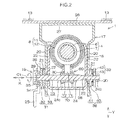
FIG. 2 is a sectional view of an essential portion of the steering device taken along the line II-II ofFIG. 1 ; -
FIG. 3A is a schematic illustration of an outer tube; -
FIG. 3B is a schematic illustration of an inner tube; -
FIG. 4 is a sectional view of an essential portion of the steering device obtained by enlarging a part ofFIG. 2 ; -
FIG. 5 is a schematic sectional view of a steering column and a rotation restriction mechanism, illustrating a state during normal times; -
FIG. 6A is a schematic sectional view of the steering column and the rotation restriction mechanism, illustrating an initial state upon a secondary collision; -
FIG. 6B is a schematic sectional view of the steering column and the rotation restriction mechanism, illustrating an intermediate state upon a secondary collision; and -
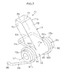
FIG. 7 is a schematic perspective view of a restriction member and an urging member of the rotation restriction mechanism. - An embodiment of the present invention will be described below with reference to the accompanying drawings.
-
FIG. 1 is a schematic sectional view illustrating a schematic configuration of a steering device according to an embodiment of the present invention. Asteering device 1 includes asteering member 2 such as a steering wheel, a steering shaft 3, to one end of which in an axial direction X thesteering member 2 is coupled, and asteering mechanism 5 coupled to the steering shaft 3 via anintermediate shaft 4 etc. - The
steering mechanism 5 is a rack-and-pinion mechanism, for example, that steers steered wheels (not illustrated) in conjunction with a steering operation of thesteering member 2. Rotation of thesteering member 2 is transferred to thesteering mechanism 5 via the steering shaft 3, theintermediate shaft 4, etc. Rotation transferred to thesteering mechanism 5 is converted into axial movement of a rack shaft (not illustrated). Consequently, the steered wheels are steered. - The steering shaft 3 includes a tubular upper shaft 6 and a
lower shaft 7 that are fitted so as to be relatively slidable through spline fitting or serration fitting, for example. The steeringmember 2 is coupled to one end of the upper shaft 6. The steering shaft 3 is expandable in the axial direction X. - The
steering device 1 includes ahollow steering column 8 that rotatably supports the steering shaft 3. The steering shaft 3 is inserted through thesteering column 8, and supported by thesteering column 8 so as to be rotatable via a plurality ofbearings 9 and 10. - The
steering column 8 includes aninner tube 11, which is an upper tube, and anouter tube 12, which is a lower tube, fitted so as to be relatively slidable. Thesteering column 8 is expandable in the axial direction X. Theinner tube 11 supports the upper shaft 6 so as to be rotatable via the bearing 9. Theinner tube 11 is coupled to the upper shaft 6 so as to be movable in accompaniment in the axial direction X of the steering shaft 3 via the bearing 9. - The
steering device 1 includes a fixedbracket 14 fixed to avehicle body 13, atilt center shaft 15 supported by the fixedbracket 14, and acolumn bracket 16 fixed to the outer periphery of theouter tube 12 and rotatably supported by thetilt center shaft 15. Thesteering column 8 and the steering shaft 3 are tiltable in a tilt direction Y about a tilt center CC which is the center axis of thetilt center shaft 15. - The
steering device 1 is configured as a steering device having a tilt adjustment mechanism that adjusts the inclined position of the steeringmember 2 in the tilt direction Y by tilting the steering shaft 3 and thesteering column 8 about the tilt center CC. - The
steering device 1 according to the embodiment does not have a telescopic adjustment function of adjusting the axial position of the steeringmember 2 by moving or expanding and contracting the steering shaft 3 and thesteering column 8 in the axial direction X. Thesteering device 1 has a function of absorbing a shock by contracting thesteering column 8 in the axial direction X together with the steering shaft 3 upon a secondary collision. - The
steering device 1 includes afirst bracket 17 fixed to thevehicle body 13, a second bracket 18 (corresponding to a distance bracket) fixed to theinner tube 11 of thesteering column 8, and alock device 19. Thelock device 19 locks the relative positions of thebrackets steering column 8 in position with respect to thevehicle body 13 to fix thesteering member 2 in position. - The
first bracket 17 includes a pair of first side plates 20 (only one of thefirst side plates 20 is illustrated inFIG. 1 ) to be tightened. Along tilt groove 21 that extends in the tilt direction Y to serve as a first insertion groove is formed in each of thefirst side plates 20. Thesecond bracket 18 includes a pair of second side plates 22 (only one of thesecond side plates 22 is illustrated inFIG. 1 ) to be tightened. A second insertion groove 23 (seeFIG. 2 ) is formed in each of thesecond side plates 22. - As illustrated in
FIG. 1 , thelock device 19 includes thefirst side plates 20 and thesecond side plates 22 to be tightened, a tighteningshaft 24 inserted through the long tilt grooves 21 (first insertion grooves) of thefirst side plates 20 and thesecond insertion grooves 23 of thesecond side plates 22, and anoperation lever 25 that is rotatable together with the tighteningshaft 24 and that is rotationally operated by a driver. A center axis C1 of the tighteningshaft 24 corresponds to the center of rotation of theoperation lever 25. Theoperation lever 25 is operated in a locking direction Z1 and an unlocking direction Z2 that is opposite to the locking direction Z1 about the center of rotation (the center axis C1 of the tightening shaft 24). - As illustrated in
FIG. 2 , thefirst bracket 17 includes anattachment plate 26 supported on thevehicle body 13, atop plate 27 fixed along theattachment plate 26, and the pair offirst side plates 20 discussed earlier which extend downward in the tilt direction Y from both ends of thetop plate 27. Thetop plate 27 and thefirst side plates 20 form a groove shape as a whole. - The
second bracket 18 includes the pair ofsecond side plates 22 discussed earlier which face the pair offirst side plates 20 of thefirst bracket 17, respectively, and acoupling plate 28 that couples between the lower ends of the pair ofsecond side plates 22 in the tilt direction Y. Thesecond bracket 18 forms a groove shape as a whole. - The tightening
shaft 24 includes a bolt that penetrates thelong tilt grooves 21 of thefirst side plates 20 of thefirst bracket 17 and thesecond insertion grooves 23 of thesecond side plates 22 of thesecond bracket 18. Ahead portion 29 provided at one end of ashaft portion 24a of the tighteningshaft 24 is fixed so as to be rotatable together with theoperation lever 25. Ascrew portion 24b provided at the other end of theshaft portion 24a of the tighteningshaft 24 is screwed to anut 30. - The
lock device 19 includes aforce conversion mechanism 31 that converts operating torque of theoperation lever 25 into an axial force of the tighteningshaft 24 as theoperation lever 25 is operated to rotate. Theforce conversion mechanism 31 functions as a tightening mechanism that locks the inclined position of the steering column 8 (hereinafter referred to as "tilt lock") after tilt adjustment by tightening thefirst side plates 20 to the respectivesecond side plates 22 as theoperation lever 25 is operated to rotate in the locking direction Z1. - The
force conversion mechanism 31 includes afirst cam 32 supported by the outer periphery of theshaft portion 24a of the tighteningshaft 24 to rotate together with theoperation lever 25, and asecond cam 33 which is supported by theshaft portion 24a of the tighteningshaft 24 and rotation of which is restricted by thelong tilt groove 21. Thesecond cam 33 functions as one tightening member that tightens one of thefirst side plates 20 to the correspondingsecond side plate 22. - The
first cam 32 is coupled to theoperation lever 25 so as to be rotatable together. Movement of thefirst cam 32 in an axial direction K with respect to the tighteningshaft 24 is restricted. Rotation of theoperation lever 25 with respect to thehead portion 29 of the tighteningshaft 24 is restricted. Thefirst cam 32 includes anannular plate 34 and aboss 35 that extends in the axial direction from theannular plate 34 to be inserted through an insertion hole of theoperation lever 25 so as to be rotatable together. - The
second cam 33 includes anannular plate 36 that faces theannular plate 34 of thefirst cam 32, and aboss 37 that extends in the axial direction from the periphery of the center hole of theannular plate 36. Theboss 37 is inserted through thelong tilt groove 21 of thefirst side plate 20 so that rotation of theboss 37 is restricted, which restricts rotation of thesecond cam 33 about the center axis C1. Theboss 37 permits rotation of the tighteningshaft 24. - The
lock device 19 includes the other tighteningmember 38 that tightens the otherfirst side plate 20 to the correspondingsecond side plate 22, thenut 30 discussed earlier, and an interposed member 39 interposed between the other tighteningmember 38 and thenut 30. - The other tightening
member 38 includes anannular plate 40 that faces the otherfirst side plate 20, and aboss 41 that extends in the axial direction from the periphery of the center hole of theannular plate 40. Theboss 41 is inserted into thelong tilt groove 21 of the otherfirst side plate 20 of thefirst bracket 17 so that rotation of theboss 41 is restricted, which restricts rotation of the other tighteningmember 38 about the center axis C1. Theboss 41 permits rotation of the tighteningshaft 24. - The
operation lever 25, thefirst cam 32, and thesecond cam 33 which serves as one tightening member are interposed between thehead portion 29 of the tighteningshaft 24 and one of thefirst side plates 20. The other tighteningmember 38 and the interposed member 39 are interposed between thenut 30 and the other of thefirst side plates 20 of thefirst bracket 17. Thefirst cam 32, the second cam 33 (one tightening member), the other tighteningmember 38, and the interposed member 39 are supported by the outer periphery of the tighteningshaft 24. The second cam 33 (one tightening member) and the other tighteningmember 38 are supported so as to be movable in the axial direction K of the tighteningshaft 24. - The interposed member 39 includes a
washer 42 interposed between thenut 30 and the tighteningmember 38, and a needle roller bearing 43 interposed between thewasher 42 and theannular plate 40 of the tighteningmember 38. - As the
operation lever 25 is rotated, thefirst cam 32 is rotated with respect to the second cam 33 (one tightening member) to move thesecond cam 33 in the axial direction K of the tighteningshaft 24 so that thefirst side plates 20 of thefirst bracket 17 are tightened between theannular plate 36 of thesecond cam 33 and theannular plate 40 of the other tighteningmember 38. - Consequently, the
first side plates 20 of thefirst bracket 17 are brought into press contact with the respectivesecond side plates 22 of thesecond bracket 18 to achieve tilt lock. - As illustrated in
FIG. 3A , theouter tube 12 includes afirst opening 51 having a rectangular shape, for example. As illustrated inFIG. 3B , theinner tube 11 includes asecond opening 52 having a rectangular shape, for example. Thesecond opening 52 includes a pair of rotation restrictededge portions inner tube 11, a drivingedge portion 55 that crosses the pair of rotation restrictededge portions edge portion 56 that faces the drivingedge portion 55 in the axial direction X. - As illustrated in
FIG. 5 , theinner tube 11 and theouter tube 12 are coupled to each other with a predetermined holding force via aresin pin 90. Theresin pin 90 is disposed in insertion holes of thetubes resin pin 90 extends over the insertion holes. Upon a secondary collision in which theinner tube 11 moves downward X2 in the axial direction, theresin pin 90 is split into two splitbodies FIG. 6A ). - As illustrated in
FIGS. 2 and4 , thesteering device 1 includes arotation restriction mechanism 60 that restricts rotation of theinner tube 11. - The
rotation restriction mechanism 60 includes the tighteningshaft 24 which constitutes a support shaft that serves as a support member, the position of which with respect to theouter tube 12 is not varied upon a secondary collision, arestriction member 70 supported by the tighteningshaft 24 so as to be relatively rotatable, and an urgingmember 80 such as a torsion spring that urges therestriction member 70. - The
restriction member 70 is displaced between an inserted position at which therestriction member 70 is inserted into thesecond opening 52 through thefirst opening 51 as illustrated inFIG. 5 and a retracted position at which therestriction member 70 is retracted from thesecond opening 52 as illustrated inFIG. 6B . The urgingmember 80 urges therestriction member 70 toward the inserted position illustrated inFIG. 5 . - As illustrated in
FIGS. 4, 5 , and7 , therestriction member 70 includes anarm 71 having abase end portion 71a and adistal end portion 71b, and aboss 72 integrally coupled to thebase end portion 71 a of thearm 71. Theboss 72 is fitted with the outer periphery of the tightening shaft 24 (anouter periphery 24c of theshaft portion 24a) so as to be relatively rotatable. - As illustrated in
FIG. 5 , when therestriction member 70 is at the inserted position, thedistal end portion 71b of thearm 71 is inserted into thesecond opening 52. As illustrated inFIG. 4 , therestriction member 70 includes a pair ofrotation restricting portions edge portions inner tube 11. As illustrated inFIG. 7 , therotation restricting portions distal end portion 71b of thearm 71. - The
restriction member 70 includes a drivenportion 75 that engages with the drivingedge portion 55 of thesecond opening 52 as illustrated inFIG. 6A upon a secondary collision. The drivenportion 75 is constituted of a cam surface inclined with respect to the axial direction X. As illustrated inFIG. 7 , the drivenportion 75 is disposed at thedistal end portion 71b of thearm 71. The drivingedge portion 55 of thesecond opening 52 of theinner tube 11 is configured to drive therestriction member 70 to the retracted position (seeFIG. 6B ) via the drivenportion 75 as illustrated inFIG. 6A upon a secondary collision. - As illustrated in
FIG. 5 , therestriction member 70 includes anextraction restricting portion 76 that engages with the extraction restrictededge portion 56 of thesecond opening 52 of theinner tube 11 to restrict extraction of theinner tube 11 from theouter tube 12. As illustrated inFIG. 7 , theextraction restricting portion 76 is disposed at thedistal end portion 71b of thearm 71. Theboss 72 of therestriction member 70 includes a pair of projectingportions base end portion 71 a of thearm 71. - As illustrated in
FIG. 7 , the urgingmember 80 includescoil portions portions boss 72, and an urgingportion 83 that couples betweenfirst ends coil portions intermediate portion 71c of thearm 71. - The urging
member 80 includesextended portions coil portions extended portions coupling plate 28 of thesecond bracket 18 as illustrated inFIG. 5 . - As illustrated in
FIG. 5 , the urgingmember 80 rotationally urges therestriction member 70 about the center axis C1 of the tightening shaft 24 (clockwise inFIG. 5 ) by use of the urgingportion 83 to urge therestriction member 70 toward the inserted position. - According to the embodiment, the
rotation restricting portions restriction member 70 engage with the rotation restrictededge portions second opening 52 as illustrated inFIG. 4 when therestriction member 70 which is urged by the urgingmember 80 is at the inserted position at which therestriction member 70 is inserted into thesecond opening 52 of theinner tube 11 through thefirst opening 51 of theouter tube 12 as illustrated inFIG. 5 . This restricts rotation of theinner tube 11. Consequently, the rigidity of thesteering column 8 in the rotational direction can be secured. - The
inner tube 11 has an opening (not illustrated) that is different from thesecond opening 52. A keylock device (not illustrated) is provided in the different opening. The keylock device includes a protruding portion that advances toward the center axis of the steering shaft 3 when an ignition key is extracted and that retracts away from the center axis of the steering shaft 3 when the ignition key is inserted. - The steering shaft 3 is provided with a keylock collar having an engagement groove. When the ignition key is extracted and the protruding portion advances to be engaged in the engagement groove, rotation of the steering shaft 3 is restricted, that is, rotation of the steering
member 2 is restricted, to establish a keylock state. Even in the keylock state, however, when an excessive torque load is applied from the outside to theinner tube 11, theinner tube 11 may rotate to release engagement between the protruding portion and the engagement groove, which may cancel the keylock state. According to the embodiment, however, rotation of theinner tube 11 is reliably restricted to secure the rigidity of thesteering column 8 in the rotational direction. Restriction of rotation does not cause cancelation of the keylock state, and can prevent occurrence of theft of the vehicle accompanied by a malfunction of the keylock device for steering lock. - When the
inner tube 11 moves downward X2 in the axial direction to contract thesteering column 8 as illustrated inFIG. 6B upon a secondary collision, the drivingedge portion 55 of thesecond opening 52 drives therestriction member 70 to the retracted position (seeFIG. 6B ) at which therestriction member 70 is retracted from thesecond opening 52 against the urgingmember 80. Thus, therotation restriction mechanism 60 does not adversely affect contraction of thesteering column 8 upon a secondary collision. As a result, stable shock absorption performance can be demonstrated. - Upon a secondary collision, the upper tube that serves as the
inner tube 11 slides with respect to the lower tube that serves as theouter tube 12 supported by thevehicle body 13 and the support shaft (tightening shaft 24). - Since the tightening
shaft 24 included in thelock device 19 which achieves tilt lock also serves as the support shaft which supports therestriction member 70, it is possible to simplify the structure. - Upon a secondary collision, the driving
edge portion 55 of thesecond opening 52 of theinner tube 11 which moves downward X2 in the axial direction drives therestriction member 70 to the retracted position (seeFIG. 6B ) via the cam surface as the drivenportion 75 which is inclined with respect to the axial direction X as illustrated inFIG. 6A . - The
extraction restricting portion 76 of therestriction member 70 engages with the extraction restrictededge portion 56 of thesecond opening 52 during normal times or after a secondary collision, which restricts extraction of theinner tube 11 from theouter tube 12 upward X1 in the axial direction. - The present invention is not limited to the embodiment described above. For example, a support shaft (not illustrated) that supports the
restriction member 70 may be provided separately from the tighteningshaft 24. - A compression spring (not illustrated) such as a compression coil spring interposed between the
intermediate portion 71c of thearm 71 of therestriction member 70 and thecoupling plate 28 may be used in place of a torsion spring as the urgingmember 80.
Claims (5)
- A steering device comprising:a steering member;a steering shaft, to one end of which the steering member is coupled;a steering column including an outer tube and an inner tube that are fitted so as to be relatively slidable with respect to each other, the steering column supporting the steering shaft and being contractable upon a secondary collision; anda rotation restriction mechanism that restricts rotation of the inner tube, wherein:the outer tube includes a first opening;the inner tube includes a second opening, the second opening including a pair of rotation restricted edge portions that face each other in a circumferential direction and a driving edge portion that crosses the pair of rotation restricted edge portions;the rotation restriction mechanism includes
a support shaft, a position of which with respect to the outer tube is not varied upon the secondary collision,
a restriction member supported on an outer periphery of the support shaft so as to be relatively rotatable, the restriction member being displaceable between an inserted position at which the restriction member is inserted into the second opening through the first opening and a retracted position at which the restriction member is retracted from the second opening, and
an urging member that urges the restriction member toward the inserted position;the restriction member includes
a rotation restricting portion that engages with a corresponding one of the rotation restricted edge portions at the inserted position to restrict relative rotation between the outer tube and the inner tube, and
a driven portion that engages with the driving edge portion upon the secondary collision; andthe driving edge portion is configured to drive the restriction member toward the retracted position via the driven portion upon the secondary collision. - The steering device according to claim 1, wherein:the outer tube is a lower tube supported by a vehicle body;the inner tube is an upper tube; andthe support shaft is supported by the vehicle body.
- The steering device according to claim 2, further comprising:a lock device, wherein:the lock device includes
a first side plate including a long tilt groove and supported on the vehicle body, a second side plate including an insertion groove and fixed to the outer tube,
a tightening shaft that serves as the support shaft inserted through the long tilt groove of the first side plate and the insertion groove of the second side plate, and
an operation lever that rotates together with the tightening shaft; whereinthe lock device is configured to fix the steering member in position by tightening the first side plate to the second side plate by operating the operation lever after the steering member is adjusted to a desired inclined position with respect to the vehicle body. - The steering device according to any one of claims 1 to 3, wherein
the driven portion is a cam surface inclined with respect to an axial direction of the inner tube. - The steering device according to any one of claims 1 to 4, wherein:the second opening includes an extraction restricted edge portion that faces the driving edge portion; andthe restriction member includes an extraction restricting portion that engages with the extraction restricted edge portion to restrict extraction of the inner tube from the outer tube.
Applications Claiming Priority (1)
| Application Number | Priority Date | Filing Date | Title |
|---|---|---|---|
| JP2014166758A JP6344606B2 (en) | 2014-08-19 | 2014-08-19 | Steering device |
Publications (2)
| Publication Number | Publication Date |
|---|---|
| EP2987700A1 true EP2987700A1 (en) | 2016-02-24 |
| EP2987700B1 EP2987700B1 (en) | 2017-10-25 |
Family
ID=53969188
Family Applications (1)
| Application Number | Title | Priority Date | Filing Date |
|---|---|---|---|
| EP15181354.0A Not-in-force EP2987700B1 (en) | 2014-08-19 | 2015-08-18 | Steering device |
Country Status (4)
| Country | Link |
|---|---|
| US (1) | US9381935B2 (en) |
| EP (1) | EP2987700B1 (en) |
| JP (1) | JP6344606B2 (en) |
| CN (1) | CN105365877B (en) |
Cited By (1)
| Publication number | Priority date | Publication date | Assignee | Title |
|---|---|---|---|---|
| EP3228522A3 (en) * | 2016-04-07 | 2018-01-17 | Jtekt Corporation | Steering apparatus |
Families Citing this family (8)
| Publication number | Priority date | Publication date | Assignee | Title |
|---|---|---|---|---|
| EP3162656B1 (en) * | 2014-09-02 | 2019-06-19 | NSK Ltd. | Steering device |
| US10046789B2 (en) * | 2015-05-19 | 2018-08-14 | Nsk Ltd. | Telescopic steering device |
| US10065671B2 (en) * | 2015-10-21 | 2018-09-04 | Nsk Ltd. | Telescopic steering column and steering device |
| JP6694739B2 (en) * | 2016-03-25 | 2020-05-20 | 富士機工株式会社 | Steering column device |
| DE102017115276B4 (en) * | 2017-07-07 | 2025-01-09 | Zf Automotive Germany Gmbh | locking device and steering column assembly |
| JP6905918B2 (en) * | 2017-11-17 | 2021-07-21 | 株式会社山田製作所 | Steering device |
| JP2021037817A (en) * | 2019-09-02 | 2021-03-11 | 富士機工株式会社 | Steering column device |
| CN114475766B (en) * | 2020-11-13 | 2025-10-17 | 株式会社山田制作所 | Steering device |
Citations (4)
| Publication number | Priority date | Publication date | Assignee | Title |
|---|---|---|---|---|
| EP2022699A2 (en) * | 2007-08-02 | 2009-02-11 | Ford Global Technologies, LLC | An adjustable steering column assembly for a motor vehicle |
| DE102008054363A1 (en) * | 2007-10-30 | 2009-05-07 | Trw Ltd., Solihull | A steering column assembly |
| EP2423073A1 (en) * | 2009-04-20 | 2012-02-29 | NSK Ltd. | Position adjustment device for steering wheel |
| JP2012162152A (en) | 2011-02-04 | 2012-08-30 | Yamada Seisakusho Co Ltd | Steering device |
Family Cites Families (10)
| Publication number | Priority date | Publication date | Assignee | Title |
|---|---|---|---|---|
| EP1520768B1 (en) * | 2002-07-10 | 2010-04-14 | Nsk Ltd., | Vehicle shock absorption type steering column device |
| JP4354762B2 (en) * | 2003-09-01 | 2009-10-28 | 日本精工株式会社 | Vehicle-adjustable steering column device |
| JP2007091118A (en) * | 2005-09-29 | 2007-04-12 | Nsk Ltd | Steering device |
| JP2009227181A (en) * | 2008-03-25 | 2009-10-08 | Nsk Ltd | Steering device |
| US7798525B2 (en) * | 2008-04-11 | 2010-09-21 | Gm Global Technology Operations, Inc. | Collapsible steering column assembly |
| JP2009292306A (en) * | 2008-06-05 | 2009-12-17 | Jtekt Corp | Shock-absorbing steering device |
| JP5293374B2 (en) * | 2009-04-20 | 2013-09-18 | 日本精工株式会社 | Steering wheel position adjustment device |
| JP2014040181A (en) * | 2012-08-22 | 2014-03-06 | Jtekt Corp | Steering device |
| JP6351009B2 (en) * | 2014-03-24 | 2018-07-04 | 株式会社ジェイテクト | Steering device |
| JP6270141B2 (en) * | 2014-03-24 | 2018-01-31 | 株式会社ジェイテクト | Steering device |
-
2014
- 2014-08-19 JP JP2014166758A patent/JP6344606B2/en not_active Expired - Fee Related
-
2015
- 2015-08-03 US US14/816,339 patent/US9381935B2/en active Active
- 2015-08-05 CN CN201510474557.3A patent/CN105365877B/en not_active Expired - Fee Related
- 2015-08-18 EP EP15181354.0A patent/EP2987700B1/en not_active Not-in-force
Patent Citations (4)
| Publication number | Priority date | Publication date | Assignee | Title |
|---|---|---|---|---|
| EP2022699A2 (en) * | 2007-08-02 | 2009-02-11 | Ford Global Technologies, LLC | An adjustable steering column assembly for a motor vehicle |
| DE102008054363A1 (en) * | 2007-10-30 | 2009-05-07 | Trw Ltd., Solihull | A steering column assembly |
| EP2423073A1 (en) * | 2009-04-20 | 2012-02-29 | NSK Ltd. | Position adjustment device for steering wheel |
| JP2012162152A (en) | 2011-02-04 | 2012-08-30 | Yamada Seisakusho Co Ltd | Steering device |
Cited By (1)
| Publication number | Priority date | Publication date | Assignee | Title |
|---|---|---|---|---|
| EP3228522A3 (en) * | 2016-04-07 | 2018-01-17 | Jtekt Corporation | Steering apparatus |
Also Published As
| Publication number | Publication date |
|---|---|
| CN105365877A (en) | 2016-03-02 |
| JP2016043703A (en) | 2016-04-04 |
| US9381935B2 (en) | 2016-07-05 |
| CN105365877B (en) | 2019-03-08 |
| US20160052537A1 (en) | 2016-02-25 |
| EP2987700B1 (en) | 2017-10-25 |
| JP6344606B2 (en) | 2018-06-20 |
Similar Documents
| Publication | Publication Date | Title |
|---|---|---|
| EP2987700B1 (en) | Steering device | |
| US9242667B2 (en) | Steering device | |
| US9545943B2 (en) | Steering device | |
| US9623898B2 (en) | Steering system | |
| EP2923919B1 (en) | Steering device | |
| US9327755B2 (en) | Steering device | |
| EP2423073B1 (en) | Position adjustment device for steering wheel | |
| US8783717B2 (en) | Steering column telescope lock | |
| EP2497696B1 (en) | Shock-absorbing steering device | |
| US10053134B2 (en) | Steering system | |
| US20150239490A1 (en) | Steering system | |
| JP6429077B2 (en) | Steering device | |
| JP6792198B2 (en) | Steering device | |
| KR101268248B1 (en) | Steering Column for Vehicle | |
| US8931804B2 (en) | Steering device | |
| JP2009208506A (en) | Impact-absorption type steering device | |
| JP2019031290A (en) | Steering device | |
| KR20120050650A (en) | Steering column for vehicle | |
| JP6440536B2 (en) | Steering device | |
| JP2016137771A (en) | Steering device | |
| KR20110113869A (en) | Steering column of automobile and steering apparatus of automobile having same |
Legal Events
| Date | Code | Title | Description |
|---|---|---|---|
| PUAI | Public reference made under article 153(3) epc to a published international application that has entered the european phase |
Free format text: ORIGINAL CODE: 0009012 |
|
| AK | Designated contracting states |
Kind code of ref document: A1 Designated state(s): AL AT BE BG CH CY CZ DE DK EE ES FI FR GB GR HR HU IE IS IT LI LT LU LV MC MK MT NL NO PL PT RO RS SE SI SK SM TR |
|
| AX | Request for extension of the european patent |
Extension state: BA ME |
|
| 17P | Request for examination filed |
Effective date: 20160712 |
|
| RBV | Designated contracting states (corrected) |
Designated state(s): AL AT BE BG CH CY CZ DE DK EE ES FI FR GB GR HR HU IE IS IT LI LT LU LV MC MK MT NL NO PL PT RO RS SE SI SK SM TR |
|
| GRAP | Despatch of communication of intention to grant a patent |
Free format text: ORIGINAL CODE: EPIDOSNIGR1 |
|
| RIC1 | Information provided on ipc code assigned before grant |
Ipc: B62D 1/19 20060101ALI20170331BHEP Ipc: B60R 25/02 20130101ALI20170331BHEP Ipc: B62D 1/184 20060101AFI20170331BHEP |
|
| INTG | Intention to grant announced |
Effective date: 20170508 |
|
| GRAS | Grant fee paid |
Free format text: ORIGINAL CODE: EPIDOSNIGR3 |
|
| GRAA | (expected) grant |
Free format text: ORIGINAL CODE: 0009210 |
|
| AK | Designated contracting states |
Kind code of ref document: B1 Designated state(s): AL AT BE BG CH CY CZ DE DK EE ES FI FR GB GR HR HU IE IS IT LI LT LU LV MC MK MT NL NO PL PT RO RS SE SI SK SM TR |
|
| REG | Reference to a national code |
Ref country code: GB Ref legal event code: FG4D |
|
| RIN1 | Information on inventor provided before grant (corrected) |
Inventor name: ISHIMURA, SHOJI |
|
| REG | Reference to a national code |
Ref country code: CH Ref legal event code: EP |
|
| REG | Reference to a national code |
Ref country code: AT Ref legal event code: REF Ref document number: 939629 Country of ref document: AT Kind code of ref document: T Effective date: 20171115 |
|
| REG | Reference to a national code |
Ref country code: IE Ref legal event code: FG4D |
|
| REG | Reference to a national code |
Ref country code: DE Ref legal event code: R096 Ref document number: 602015005545 Country of ref document: DE |
|
| REG | Reference to a national code |
Ref country code: NL Ref legal event code: MP Effective date: 20171025 |
|
| REG | Reference to a national code |
Ref country code: LT Ref legal event code: MG4D |
|
| REG | Reference to a national code |
Ref country code: AT Ref legal event code: MK05 Ref document number: 939629 Country of ref document: AT Kind code of ref document: T Effective date: 20171025 |
|
| PG25 | Lapsed in a contracting state [announced via postgrant information from national office to epo] |
Ref country code: NL Free format text: LAPSE BECAUSE OF FAILURE TO SUBMIT A TRANSLATION OF THE DESCRIPTION OR TO PAY THE FEE WITHIN THE PRESCRIBED TIME-LIMIT Effective date: 20171025 |
|
| PG25 | Lapsed in a contracting state [announced via postgrant information from national office to epo] |
Ref country code: ES Free format text: LAPSE BECAUSE OF FAILURE TO SUBMIT A TRANSLATION OF THE DESCRIPTION OR TO PAY THE FEE WITHIN THE PRESCRIBED TIME-LIMIT Effective date: 20171025 Ref country code: SE Free format text: LAPSE BECAUSE OF FAILURE TO SUBMIT A TRANSLATION OF THE DESCRIPTION OR TO PAY THE FEE WITHIN THE PRESCRIBED TIME-LIMIT Effective date: 20171025 Ref country code: NO Free format text: LAPSE BECAUSE OF FAILURE TO SUBMIT A TRANSLATION OF THE DESCRIPTION OR TO PAY THE FEE WITHIN THE PRESCRIBED TIME-LIMIT Effective date: 20180125 Ref country code: LT Free format text: LAPSE BECAUSE OF FAILURE TO SUBMIT A TRANSLATION OF THE DESCRIPTION OR TO PAY THE FEE WITHIN THE PRESCRIBED TIME-LIMIT Effective date: 20171025 Ref country code: FI Free format text: LAPSE BECAUSE OF FAILURE TO SUBMIT A TRANSLATION OF THE DESCRIPTION OR TO PAY THE FEE WITHIN THE PRESCRIBED TIME-LIMIT Effective date: 20171025 |
|
| PG25 | Lapsed in a contracting state [announced via postgrant information from national office to epo] |
Ref country code: HR Free format text: LAPSE BECAUSE OF FAILURE TO SUBMIT A TRANSLATION OF THE DESCRIPTION OR TO PAY THE FEE WITHIN THE PRESCRIBED TIME-LIMIT Effective date: 20171025 Ref country code: GR Free format text: LAPSE BECAUSE OF FAILURE TO SUBMIT A TRANSLATION OF THE DESCRIPTION OR TO PAY THE FEE WITHIN THE PRESCRIBED TIME-LIMIT Effective date: 20180126 Ref country code: AT Free format text: LAPSE BECAUSE OF FAILURE TO SUBMIT A TRANSLATION OF THE DESCRIPTION OR TO PAY THE FEE WITHIN THE PRESCRIBED TIME-LIMIT Effective date: 20171025 Ref country code: IS Free format text: LAPSE BECAUSE OF FAILURE TO SUBMIT A TRANSLATION OF THE DESCRIPTION OR TO PAY THE FEE WITHIN THE PRESCRIBED TIME-LIMIT Effective date: 20180225 Ref country code: RS Free format text: LAPSE BECAUSE OF FAILURE TO SUBMIT A TRANSLATION OF THE DESCRIPTION OR TO PAY THE FEE WITHIN THE PRESCRIBED TIME-LIMIT Effective date: 20171025 Ref country code: LV Free format text: LAPSE BECAUSE OF FAILURE TO SUBMIT A TRANSLATION OF THE DESCRIPTION OR TO PAY THE FEE WITHIN THE PRESCRIBED TIME-LIMIT Effective date: 20171025 Ref country code: BG Free format text: LAPSE BECAUSE OF FAILURE TO SUBMIT A TRANSLATION OF THE DESCRIPTION OR TO PAY THE FEE WITHIN THE PRESCRIBED TIME-LIMIT Effective date: 20180125 |
|
| REG | Reference to a national code |
Ref country code: FR Ref legal event code: PLFP Year of fee payment: 4 |
|
| REG | Reference to a national code |
Ref country code: DE Ref legal event code: R097 Ref document number: 602015005545 Country of ref document: DE |
|
| PG25 | Lapsed in a contracting state [announced via postgrant information from national office to epo] |
Ref country code: DK Free format text: LAPSE BECAUSE OF FAILURE TO SUBMIT A TRANSLATION OF THE DESCRIPTION OR TO PAY THE FEE WITHIN THE PRESCRIBED TIME-LIMIT Effective date: 20171025 Ref country code: CZ Free format text: LAPSE BECAUSE OF FAILURE TO SUBMIT A TRANSLATION OF THE DESCRIPTION OR TO PAY THE FEE WITHIN THE PRESCRIBED TIME-LIMIT Effective date: 20171025 Ref country code: SK Free format text: LAPSE BECAUSE OF FAILURE TO SUBMIT A TRANSLATION OF THE DESCRIPTION OR TO PAY THE FEE WITHIN THE PRESCRIBED TIME-LIMIT Effective date: 20171025 Ref country code: CY Free format text: LAPSE BECAUSE OF FAILURE TO SUBMIT A TRANSLATION OF THE DESCRIPTION OR TO PAY THE FEE WITHIN THE PRESCRIBED TIME-LIMIT Effective date: 20171025 Ref country code: EE Free format text: LAPSE BECAUSE OF FAILURE TO SUBMIT A TRANSLATION OF THE DESCRIPTION OR TO PAY THE FEE WITHIN THE PRESCRIBED TIME-LIMIT Effective date: 20171025 |
|
| PG25 | Lapsed in a contracting state [announced via postgrant information from national office to epo] |
Ref country code: PL Free format text: LAPSE BECAUSE OF FAILURE TO SUBMIT A TRANSLATION OF THE DESCRIPTION OR TO PAY THE FEE WITHIN THE PRESCRIBED TIME-LIMIT Effective date: 20171025 Ref country code: RO Free format text: LAPSE BECAUSE OF FAILURE TO SUBMIT A TRANSLATION OF THE DESCRIPTION OR TO PAY THE FEE WITHIN THE PRESCRIBED TIME-LIMIT Effective date: 20171025 Ref country code: SM Free format text: LAPSE BECAUSE OF FAILURE TO SUBMIT A TRANSLATION OF THE DESCRIPTION OR TO PAY THE FEE WITHIN THE PRESCRIBED TIME-LIMIT Effective date: 20171025 Ref country code: IT Free format text: LAPSE BECAUSE OF FAILURE TO SUBMIT A TRANSLATION OF THE DESCRIPTION OR TO PAY THE FEE WITHIN THE PRESCRIBED TIME-LIMIT Effective date: 20171025 |
|
| PLBE | No opposition filed within time limit |
Free format text: ORIGINAL CODE: 0009261 |
|
| STAA | Information on the status of an ep patent application or granted ep patent |
Free format text: STATUS: NO OPPOSITION FILED WITHIN TIME LIMIT |
|
| 26N | No opposition filed |
Effective date: 20180726 |
|
| PG25 | Lapsed in a contracting state [announced via postgrant information from national office to epo] |
Ref country code: SI Free format text: LAPSE BECAUSE OF FAILURE TO SUBMIT A TRANSLATION OF THE DESCRIPTION OR TO PAY THE FEE WITHIN THE PRESCRIBED TIME-LIMIT Effective date: 20171025 |
|
| PG25 | Lapsed in a contracting state [announced via postgrant information from national office to epo] |
Ref country code: MC Free format text: LAPSE BECAUSE OF FAILURE TO SUBMIT A TRANSLATION OF THE DESCRIPTION OR TO PAY THE FEE WITHIN THE PRESCRIBED TIME-LIMIT Effective date: 20171025 |
|
| REG | Reference to a national code |
Ref country code: CH Ref legal event code: PL |
|
| PG25 | Lapsed in a contracting state [announced via postgrant information from national office to epo] |
Ref country code: LU Free format text: LAPSE BECAUSE OF NON-PAYMENT OF DUE FEES Effective date: 20180818 Ref country code: CH Free format text: LAPSE BECAUSE OF NON-PAYMENT OF DUE FEES Effective date: 20180831 Ref country code: LI Free format text: LAPSE BECAUSE OF NON-PAYMENT OF DUE FEES Effective date: 20180831 |
|
| REG | Reference to a national code |
Ref country code: BE Ref legal event code: MM Effective date: 20180831 |
|
| REG | Reference to a national code |
Ref country code: IE Ref legal event code: MM4A |
|
| PG25 | Lapsed in a contracting state [announced via postgrant information from national office to epo] |
Ref country code: IE Free format text: LAPSE BECAUSE OF NON-PAYMENT OF DUE FEES Effective date: 20180818 |
|
| PG25 | Lapsed in a contracting state [announced via postgrant information from national office to epo] |
Ref country code: BE Free format text: LAPSE BECAUSE OF NON-PAYMENT OF DUE FEES Effective date: 20180831 |
|
| PG25 | Lapsed in a contracting state [announced via postgrant information from national office to epo] |
Ref country code: MT Free format text: LAPSE BECAUSE OF NON-PAYMENT OF DUE FEES Effective date: 20180818 |
|
| PG25 | Lapsed in a contracting state [announced via postgrant information from national office to epo] |
Ref country code: TR Free format text: LAPSE BECAUSE OF FAILURE TO SUBMIT A TRANSLATION OF THE DESCRIPTION OR TO PAY THE FEE WITHIN THE PRESCRIBED TIME-LIMIT Effective date: 20171025 |
|
| GBPC | Gb: european patent ceased through non-payment of renewal fee |
Effective date: 20190818 |
|
| PG25 | Lapsed in a contracting state [announced via postgrant information from national office to epo] |
Ref country code: PT Free format text: LAPSE BECAUSE OF FAILURE TO SUBMIT A TRANSLATION OF THE DESCRIPTION OR TO PAY THE FEE WITHIN THE PRESCRIBED TIME-LIMIT Effective date: 20171025 |
|
| PG25 | Lapsed in a contracting state [announced via postgrant information from national office to epo] |
Ref country code: MK Free format text: LAPSE BECAUSE OF NON-PAYMENT OF DUE FEES Effective date: 20171025 Ref country code: HU Free format text: LAPSE BECAUSE OF FAILURE TO SUBMIT A TRANSLATION OF THE DESCRIPTION OR TO PAY THE FEE WITHIN THE PRESCRIBED TIME-LIMIT; INVALID AB INITIO Effective date: 20150818 |
|
| PG25 | Lapsed in a contracting state [announced via postgrant information from national office to epo] |
Ref country code: AL Free format text: LAPSE BECAUSE OF FAILURE TO SUBMIT A TRANSLATION OF THE DESCRIPTION OR TO PAY THE FEE WITHIN THE PRESCRIBED TIME-LIMIT Effective date: 20171025 |
|
| PG25 | Lapsed in a contracting state [announced via postgrant information from national office to epo] |
Ref country code: GB Free format text: LAPSE BECAUSE OF NON-PAYMENT OF DUE FEES Effective date: 20190818 |
|
| PGFP | Annual fee paid to national office [announced via postgrant information from national office to epo] |
Ref country code: FR Payment date: 20230703 Year of fee payment: 9 Ref country code: DE Payment date: 20230627 Year of fee payment: 9 |
|
| REG | Reference to a national code |
Ref country code: DE Ref legal event code: R119 Ref document number: 602015005545 Country of ref document: DE |
|
| PG25 | Lapsed in a contracting state [announced via postgrant information from national office to epo] |
Ref country code: DE Free format text: LAPSE BECAUSE OF NON-PAYMENT OF DUE FEES Effective date: 20250301 |
|
| PG25 | Lapsed in a contracting state [announced via postgrant information from national office to epo] |
Ref country code: FR Free format text: LAPSE BECAUSE OF NON-PAYMENT OF DUE FEES Effective date: 20240831 |