EP2987660A1 - Procédé d'adhésion de composants rigides à un pneu - Google Patents
Procédé d'adhésion de composants rigides à un pneu Download PDFInfo
- Publication number
- EP2987660A1 EP2987660A1 EP15180160.2A EP15180160A EP2987660A1 EP 2987660 A1 EP2987660 A1 EP 2987660A1 EP 15180160 A EP15180160 A EP 15180160A EP 2987660 A1 EP2987660 A1 EP 2987660A1
- Authority
- EP
- European Patent Office
- Prior art keywords
- tire
- rubber
- mounting surface
- support frame
- pump
- Prior art date
- Legal status (The legal status is an assumption and is not a legal conclusion. Google has not performed a legal analysis and makes no representation as to the accuracy of the status listed.)
- Withdrawn
Links
Images


Classifications
-
- B—PERFORMING OPERATIONS; TRANSPORTING
- B60—VEHICLES IN GENERAL
- B60C—VEHICLE TYRES; TYRE INFLATION; TYRE CHANGING; CONNECTING VALVES TO INFLATABLE ELASTIC BODIES IN GENERAL; DEVICES OR ARRANGEMENTS RELATED TO TYRES
- B60C23/00—Devices for measuring, signalling, controlling, or distributing tyre pressure or temperature, specially adapted for mounting on vehicles; Arrangement of tyre inflating devices on vehicles, e.g. of pumps or of tanks; Tyre cooling arrangements
- B60C23/10—Arrangement of tyre-inflating pumps mounted on vehicles
- B60C23/12—Arrangement of tyre-inflating pumps mounted on vehicles operated by a running wheel
- B60C23/121—Arrangement of tyre-inflating pumps mounted on vehicles operated by a running wheel the pumps being mounted on the tyres
- B60C23/123—Elongate peristaltic pumps
-
- B—PERFORMING OPERATIONS; TRANSPORTING
- B29—WORKING OF PLASTICS; WORKING OF SUBSTANCES IN A PLASTIC STATE IN GENERAL
- B29D—PRODUCING PARTICULAR ARTICLES FROM PLASTICS OR FROM SUBSTANCES IN A PLASTIC STATE
- B29D30/00—Producing pneumatic or solid tyres or parts thereof
- B29D30/0061—Accessories, details or auxiliary operations not otherwise provided for
-
- B—PERFORMING OPERATIONS; TRANSPORTING
- B29—WORKING OF PLASTICS; WORKING OF SUBSTANCES IN A PLASTIC STATE IN GENERAL
- B29D—PRODUCING PARTICULAR ARTICLES FROM PLASTICS OR FROM SUBSTANCES IN A PLASTIC STATE
- B29D30/00—Producing pneumatic or solid tyres or parts thereof
- B29D30/06—Pneumatic tyres or parts thereof (e.g. produced by casting, moulding, compression moulding, injection moulding, centrifugal casting)
- B29D30/0681—Parts of pneumatic tyres; accessories, auxiliary operations
-
- B—PERFORMING OPERATIONS; TRANSPORTING
- B60—VEHICLES IN GENERAL
- B60C—VEHICLE TYRES; TYRE INFLATION; TYRE CHANGING; CONNECTING VALVES TO INFLATABLE ELASTIC BODIES IN GENERAL; DEVICES OR ARRANGEMENTS RELATED TO TYRES
- B60C23/00—Devices for measuring, signalling, controlling, or distributing tyre pressure or temperature, specially adapted for mounting on vehicles; Arrangement of tyre inflating devices on vehicles, e.g. of pumps or of tanks; Tyre cooling arrangements
- B60C23/10—Arrangement of tyre-inflating pumps mounted on vehicles
- B60C23/12—Arrangement of tyre-inflating pumps mounted on vehicles operated by a running wheel
- B60C23/135—Arrangement of tyre-inflating pumps mounted on vehicles operated by a running wheel activated due to tyre deformation
-
- B—PERFORMING OPERATIONS; TRANSPORTING
- B60—VEHICLES IN GENERAL
- B60C—VEHICLE TYRES; TYRE INFLATION; TYRE CHANGING; CONNECTING VALVES TO INFLATABLE ELASTIC BODIES IN GENERAL; DEVICES OR ARRANGEMENTS RELATED TO TYRES
- B60C5/00—Inflatable pneumatic tyres or inner tubes
-
- B—PERFORMING OPERATIONS; TRANSPORTING
- B29—WORKING OF PLASTICS; WORKING OF SUBSTANCES IN A PLASTIC STATE IN GENERAL
- B29D—PRODUCING PARTICULAR ARTICLES FROM PLASTICS OR FROM SUBSTANCES IN A PLASTIC STATE
- B29D30/00—Producing pneumatic or solid tyres or parts thereof
- B29D30/0061—Accessories, details or auxiliary operations not otherwise provided for
- B29D2030/0072—Attaching fasteners to tyres, e.g. patches, in order to connect devices to tyres
-
- B—PERFORMING OPERATIONS; TRANSPORTING
- B29—WORKING OF PLASTICS; WORKING OF SUBSTANCES IN A PLASTIC STATE IN GENERAL
- B29D—PRODUCING PARTICULAR ARTICLES FROM PLASTICS OR FROM SUBSTANCES IN A PLASTIC STATE
- B29D30/00—Producing pneumatic or solid tyres or parts thereof
- B29D30/0061—Accessories, details or auxiliary operations not otherwise provided for
- B29D2030/0094—Tyres been capable of generating, e.g. recovering, energy
Definitions
- the invention relates generally to tires and more specifically, to adhering mechanical components to a tire.
- An air maintenance feature typically includes rigid mechanical components such as an air filter, regulator or valve mechanism. These mechanical components must be secured to the tire, and be able to sustain rotational and centrifugal forces. These devices must also be assembled in such a way to minimize the stresses at the bonding interfaces and allow for ease of assembly.
- the invention relates to a tire and pump assemply in accordance with claim 1 and to methods in accordance with claim 4 or 5 respectively.
- a method of mounting a device to a tire comprising the following steps: buffing an inside surface of the tire, forming a rubber layer and a rubber extension on a mounting surface of the device, wherein the rubber extension extends past the support frame; applying rubber cement to the mounting surface and then affixing the mounting surface of the device to the inside surface; and then curing the rubber cement.
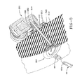
- a tire assembly 10 includes a tire 12, a pump assembly 14, and a tire wheel 16.
- the tire mounts in a conventional fashion to a wheel having a rim body 28 with rim mounting surfaces 22.
- An annular rim body 28 joins the rim mounting surfaces 22 and supports the tire assembly as shown.
- the tire is of conventional construction, having a pair of sidewalls 32 extending from opposite bead areas 34 to a crown or tire tread region 38.
- the tire and rim 28 enclose an interior tire cavity 40 which is filled with air.
- the tire assembly includes a pump 14 having a pump passageway 42 that is mounted or located in the tire in a channel 44, preferably near the bead region 34 of the sidewall.
- the pump passageway 42 may be formed of a discrete tube 42 made of a resilient, flexible material such as plastic, elastomer or rubber compounds, and is capable of withstanding repeated deformation cycles when the tube is deformed into a flattened condition subject to external force and, upon removal of such force, returns to an original condition.
- the tube is of a diameter sufficient to operatively pass a volume of air sufficient for the purposes described herein and allowing a positioning of the tube in an operable location within the tire assembly as will be described.
- the tube has an elliptical cross-sectional shape, although other shapes such as round may be utilized.
- the pump passageway itself may also be integrally formed or molded into the sidewall of the tire during vulcanization, eliminating the need for an inserted tube.
- An integrally formed pump passageway is preferably made by building into a selected green tire component such as a chafer, a removable strip made of wire or silicone. The component is built into the tire and cured. The removable strip is then removed post cure to form a molded in or integrally formed pump air passageway.
- pump passageway refers either to installed tubes or an integrally molded in passageway.
- the location selected for the pump passageway within the tire may be within a tire component residing within a high flex region of the tire, sufficient to progressively collapse the internal hollow air passageway as the tire rotates under load thereby conveying air along the air passageway from the inlet to the pump outlet.
- the pump air passageway 42 has an inlet end 42a and an outlet end 42b in fluid communication with a regulator or valve assembly 200, as shown in Figure 3 .
- the regulator assembly is preferably mounted inside the tire. Examples of pressure regulators or valve systems suitable for use with the invention are disclosed in US-A-2013/0048176 , US-A-2013/0048177 and US-A-2013/0048178 , which are hereby incorporated by reference.
- the inlet end 42a and the outlet end 42b are spaced apart approximately 360 degrees forming an annular pump assembly. However, the inlet and outlet ends may be spaced apart 90 degrees, 180 degrees, etc.
- An air filter assembly 300 is positioned on the outer sidewall of the tire, opposite the regulator assembly 200 and in the vicinity of the pump passageways, as shown in Figures 2-3 .
- the air filter assembly filters the outside air and communicates the filtered air to the regulator assembly 200 via passage tube 406.
- One or more layers of filter media 600 is received in the internal cavity 308 of the filter assembly 300.
- the filter media may be a woven or nonwoven fiber, foam, spun fiberglass, charcoal, or other materials known to those skilled the art.
- a membrane such as PTFE GoreTex may be used, alone or in combination with the filter media.
- the regulator assembly 200 is shown in Figures 4 - 6 .
- the regulator assembly 200 is operable to control the amount of inlet air to the pump system 42. If the tire cavity pressure falls below a set trigger pressure, the regulator assembly allows filtered air to enter the regulator assembly inlet port 222 through inlet hole 202, and then through to the pump passageway 42.
- the regulator assembly may allow airflow into the pump system through an air outlet port 210.
- the regulator assembly also may control the flow of air from the pump into the tire cavity, as well as prevent cavity air from back flowing into the pump passageways.
- the regulator assembly 200 is preferably affixed to the inside of the tire, near the bead area.
- the regulator assembly 200 is detachably mounted to a docking station 204.
- the docking station 204 has a lower surface 206 that is permanently affixed to the inside of the tire.
- the docking station 204 has an inlet port 202 that is in fluid communication with a central air conduit 210, opposite the inlet 202.
- the central air conduit extends from the upper surface 208 of the docking station to the inlet 202.
- the central air conduit 210 is in fluid communication with the air filter assembly 300, and communicates filtered air to the regulator assembly inlet 222 as shown in Figure 3 .
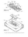
- FIG. 6 illustrates the docking station support frame 212 without the rubber encasement.
- the support frame 212 has an upper surface 208 that connects to the lower surface of the regulator.
- a plurality of pronged connectors 214 extend from the upper surface and have a tabbed portion 215 that snapped into receptacles 211 inside the regulator.
- the upper surface of the docking station has a regulator outlet conduit 207 which communicates fluid from the regulator outlet 218 to the pump inlet 42a.
- the upper surface of the docking station further includes a regulator inlet conduit 209 which communicates pump fluid from the pump outlet 42b to the regulator inlet 220.
- the docking station has a rubber layer 500 molded over the support frame.
- the cross-section of the support frame 212 preferably has a flanged surface 213 surrounding the support frame.
- the rubber layer is molded around the sides of the docking station and along the flanged surface 213 and along the bottom surface 216 of the support frame. As shown in Fig 4 , the rubber layer has a rubber flange or extension 510 which extends outward the support frame. The rubber flange 510 extends past the flanged surface 213 1-3 cm on all sides. Thus the footprint of rubber layer is greater than the footprint of the support frame.
- the thickness of the rubber layer is in the range of 1-4 mm, preferably 2-3 mm.
- the following steps are followed to mount the docking station 204 to the inside surface of the tire. These steps could also be used to mount any mechanical device, including the regulator without the docking station.
- the lower mounting surface 216 and sides 201 including the flanged surface 213 are buffed with abrasive material such as sandpaper.
- the mounting surface and sides of the docking station are pretreated with Chemlock or other suitable adhesive, ensuring the holes 202, 203, 205 located on the lower surface of the docking station are protected from the application of adhesive.
- the docking station is placed in a mold 600, so that the upper surface 208 is seated against a lower surface 602 of the mold 600 as shown in figure 7 .
- Green rubber or elastomer is placed in the mold to enrobe the lower mounting surface and sides of the docking station with rubber/elastomer and to form a rubber flange on the lower mounting surface.
- a wide variety of rubbers would work, such as sidewall compound, cushion gum, apex etc.
- the mold forms an extension or thin layer of rubber wherein the periphery of the rubber flange extends 2-3 cm outward of the mounting surface.
- the thickness of the rubber is about 1 to 2 mm.
- the coating of rubber may be cured or partially cured about the docking station housing.
- the rubber lower mounting surface and sides, including the rubber flange is buffed.
- a green rubber patch 1100 is used to secure the docking station to the tire inner liner surface.
- the docking station is affixed to the tire sidewall.
- the green rubber patch 1100 is preferably larger in size than the mounting surface of the docking station.
- the rubber patch 1100 is coated with a suitable adhesive on both sides and then inserted onto the inner surface of the tire.
- the patch 1100 may require holes that are aligned with holes of tire and the device to be mounted.
- One suitable adhesive is Fast Dry Self-vulcanizing Cement made by the Rubber Patch Company.
- the patch 1100 is then stitched.
- the device mounting surface is mounted over the rubber patch 1100, ensuring the rubber patch holes are aligned with the device holes and any tire holes.
- the device is then clamped to the tire, and then allowed to cure at ambient temperature or with heat, depending upon the adhesive selected.
Applications Claiming Priority (1)
| Application Number | Priority Date | Filing Date | Title |
|---|---|---|---|
| US14/464,825 US20160052352A1 (en) | 2014-08-21 | 2014-08-21 | Method of adhesion of rigid components to a tire |
Publications (1)
| Publication Number | Publication Date |
|---|---|
| EP2987660A1 true EP2987660A1 (fr) | 2016-02-24 |
Family
ID=53794085
Family Applications (1)
| Application Number | Title | Priority Date | Filing Date |
|---|---|---|---|
| EP15180160.2A Withdrawn EP2987660A1 (fr) | 2014-08-21 | 2015-08-07 | Procédé d'adhésion de composants rigides à un pneu |
Country Status (2)
| Country | Link |
|---|---|
| US (1) | US20160052352A1 (fr) |
| EP (1) | EP2987660A1 (fr) |
Families Citing this family (3)
| Publication number | Priority date | Publication date | Assignee | Title |
|---|---|---|---|---|
| US9604511B2 (en) * | 2015-08-11 | 2017-03-28 | The Goodyear Tire & Rubber Company | Air maintenance pumping assembly and tire |
| WO2017105842A1 (fr) * | 2015-12-15 | 2017-06-22 | Bridgestone Americas Tire Operations, Llc | Mécanisme de fixation pour capteurs montés sur un pneu |
| EP4149435A1 (fr) | 2020-05-14 | 2023-03-22 | Modernatx, Inc. | Compositions de lnp comprenant un agent thérapeutique à base d'arnm et une molécule effectrice |
Citations (7)
| Publication number | Priority date | Publication date | Assignee | Title |
|---|---|---|---|---|
| EP1006009A2 (fr) * | 1998-12-04 | 2000-06-07 | Bridgestone/Firestone, Inc. | Procédé pour fixer un dispositif électronique à un bandage pneumatique |
| US20020174925A1 (en) * | 1998-02-10 | 2002-11-28 | Wilson Paul B. | Electronic monitoring device and patch assembly |
| JP2009018607A (ja) * | 2007-07-10 | 2009-01-29 | Bridgestone Corp | 検知装置固定用パッチ、タイヤ及び検知装置固定方法 |
| US20130048178A1 (en) | 2011-08-30 | 2013-02-28 | The Goodyear Tire & Rubber Company | Self-inflating tire |
| US20130048177A1 (en) | 2011-08-30 | 2013-02-28 | The Goodyear Tire & Rubber Company | Self-inflating tire and pressure regulator |
| US20130048176A1 (en) | 2011-08-30 | 2013-02-28 | The Goodyear Tire & Rubber Company | Self-inflating tire |
| WO2015105848A2 (fr) * | 2014-01-07 | 2015-07-16 | Eaton Corporation | Régulateur d'air de pneu à gonflage automatique |
Family Cites Families (6)
| Publication number | Priority date | Publication date | Assignee | Title |
|---|---|---|---|---|
| US4485136A (en) * | 1983-03-21 | 1984-11-27 | The Firestone Tire & Rubber Company | Ambient temperature repair of elastomeric articles having a hollow therein |
| US6217683B1 (en) * | 1998-02-12 | 2001-04-17 | Michelin Recherche Et Technique S.A. | Monitored vehicle tire and monitor retainer assembly |
| US6388567B1 (en) * | 1999-04-29 | 2002-05-14 | Bridgestone/Firestone North American Tire, Llc | Combination monitoring device and patch for a pneumatic tire and method of installing the same |
| JP5928935B2 (ja) * | 2008-08-29 | 2016-06-01 | カンパニー ジェネラレ デ エスタブリシュメンツ ミシュラン | 1‐dタイヤ用装置 |
| US8596117B2 (en) * | 2011-10-03 | 2013-12-03 | Bridgestone Americas Tire Operations, Llc | Attachment patch for mounting various devices |
| US20150059953A1 (en) * | 2013-08-30 | 2015-03-05 | The Goodyear Tire & Rubber Company | Method of assembly of air maintenance tire system |
-
2014
- 2014-08-21 US US14/464,825 patent/US20160052352A1/en not_active Abandoned
-
2015
- 2015-08-07 EP EP15180160.2A patent/EP2987660A1/fr not_active Withdrawn
Patent Citations (7)
| Publication number | Priority date | Publication date | Assignee | Title |
|---|---|---|---|---|
| US20020174925A1 (en) * | 1998-02-10 | 2002-11-28 | Wilson Paul B. | Electronic monitoring device and patch assembly |
| EP1006009A2 (fr) * | 1998-12-04 | 2000-06-07 | Bridgestone/Firestone, Inc. | Procédé pour fixer un dispositif électronique à un bandage pneumatique |
| JP2009018607A (ja) * | 2007-07-10 | 2009-01-29 | Bridgestone Corp | 検知装置固定用パッチ、タイヤ及び検知装置固定方法 |
| US20130048178A1 (en) | 2011-08-30 | 2013-02-28 | The Goodyear Tire & Rubber Company | Self-inflating tire |
| US20130048177A1 (en) | 2011-08-30 | 2013-02-28 | The Goodyear Tire & Rubber Company | Self-inflating tire and pressure regulator |
| US20130048176A1 (en) | 2011-08-30 | 2013-02-28 | The Goodyear Tire & Rubber Company | Self-inflating tire |
| WO2015105848A2 (fr) * | 2014-01-07 | 2015-07-16 | Eaton Corporation | Régulateur d'air de pneu à gonflage automatique |
Also Published As
| Publication number | Publication date |
|---|---|
| US20160052352A1 (en) | 2016-02-25 |
Similar Documents
| Publication | Publication Date | Title |
|---|---|---|
| EP2746074B1 (fr) | Pneumatique doté d'un système de fixation intégré | |
| EP2842776B1 (fr) | Ensemble de pneu et procédé de fabrication d'un ensemble de pneu | |
| EP2987660A1 (fr) | Procédé d'adhésion de composants rigides à un pneu | |
| US9016118B2 (en) | Mounting structure | |
| EP2746072B1 (fr) | Système de soupape compacte pour pneu autogonflant | |
| KR20120056213A (ko) | 자가-팽창 타이어용 인라인 펌핑 조립체 | |
| EP2565061A1 (fr) | Pneu autogonflant et régulateur de pression pneumatique | |
| EP2883720A1 (fr) | Ensemble filtre pour pneumatique à air de maintenance | |
| US9259975B2 (en) | Tire with outer groove containing bonded tube | |
| CN108602292B (zh) | 使用中间区段形成非充气轮胎的方法 | |
| US11077633B2 (en) | Method of forming non-pneumatic tire including pressure application between an intermediate section and an outer shear band ring | |
| US9056435B2 (en) | Securing to a pneumatic tire | |
| EP2886314B1 (fr) | Appareil de pneu et procédé de fabrication d'un ensemble de pneu | |
| JP2015117015A5 (fr) | ||
| US20170057307A1 (en) | Method of adhesion of rigid components to a tire | |
| EP2842775B1 (fr) | Pneu comprenant un ensemble de filtre | |
| US11554614B2 (en) | Tire with means for setting out studs at the tire surface, and method | |
| EP2455240B1 (fr) | Procédé de fabrication d'un pneu autogonflant | |
| JP2018058579A (ja) | エアメンテナンスタイヤ用の連結部材およびエアメンテナンスタイヤ用の連結部材を形成する方法 | |
| EP3068617B1 (fr) | Procédé de formation d'un pneu rechapé utilisant une opération de dégazage | |
| WO2015116181A1 (fr) | Procédés de formation d'un pneu rechapé |
Legal Events
| Date | Code | Title | Description |
|---|---|---|---|
| PUAI | Public reference made under article 153(3) epc to a published international application that has entered the european phase |
Free format text: ORIGINAL CODE: 0009012 |
|
| AK | Designated contracting states |
Kind code of ref document: A1 Designated state(s): AL AT BE BG CH CY CZ DE DK EE ES FI FR GB GR HR HU IE IS IT LI LT LU LV MC MK MT NL NO PL PT RO RS SE SI SK SM TR |
|
| AX | Request for extension of the european patent |
Extension state: BA ME |
|
| 17P | Request for examination filed |
Effective date: 20160824 |
|
| RBV | Designated contracting states (corrected) |
Designated state(s): AL AT BE BG CH CY CZ DE DK EE ES FI FR GB GR HR HU IE IS IT LI LT LU LV MC MK MT NL NO PL PT RO RS SE SI SK SM TR |
|
| STAA | Information on the status of an ep patent application or granted ep patent |
Free format text: STATUS: THE APPLICATION HAS BEEN WITHDRAWN |
|
| 18W | Application withdrawn |
Effective date: 20180405 |